


Abstract
Under severe flight conditions such as high Mach number and large angle of attack, the aerodynamic environment of guided rockets exhibits highly nonlinear and strongly coupled characteristics. Significant dynamic coupling effects exist among the pitch, yaw, and roll channels, and aerodynamic parameters are subject to considerable uncertainties due to shocks, flow separation, and other factors. These issues collectively pose serious challenges to traditional control design methods based on linearized models. To address these challenges, this paper proposes a variable-gain adaptive decoupling control method. First, based on the classical feedforward decoupling concept, a decoupling controller is designed to preliminarily suppress inter-channel coupling effects. To further cope with aerodynamic parameter perturbations and model uncertainties, a model reference adaptive control framework is introduced, and an online parameter compensation mechanism is constructed to adjust controller parameters in real time according to changes in the aerodynamic environment. Additionally, by defining and estimating a system coupling degree in real time, a variable-gain adaptive law based on coupling degree is designed. This allows the decoupling effort to be dynamically adjusted according to the coupling degree, ensuring effective decoupling while avoiding performance degradation due to over-compensation. Simulation experiments conducted under typical high-dynamic flight scenarios demonstrate that, compared to traditional methods, the proposed approach effectively suppresses inter-channel coupling disturbances and significantly enhances system stability and robustness under parameter uncertainties and external disturbances. This provides a feasible technical solution for controlling guided rockets under extreme aerodynamic conditions.
1. Introduction
The guided rocket is a kind of precision-guided weapon, which can carry out precise strikes on different operational targets, and is being widely studied and improved by countries all over the world. In order to increase range capability and improve maneuverability, guided rockets not only tend to adopt a large slenderness ratio design, but also require high angle of attack maneuvering during flight. With the stricter of tactical demands and the enhancement of control coupling, the requirements for control system performance are consequently increasing [1,2].
The traditional method for designing autopilot is as follows: Firstly, the designer ignores the coupling factors and establishes a dynamic model of guided rocket. Then, the classical control theory is used to analyze and design each channel of the autopilot independently, while retaining a certain degree of stability margin. Finally, the neglected coupling factors are introduced into the model to verify the autopilot’s robustness [3,4]. However, this traditional method has obvious theoretical defects: when the coupling factors are large enough, the coupling terms will change the structure of dynamic model and even cause the autopilot instability. Therefore, the traditional method for design autopilot has become difficult to meet the actual engineering needs at the present stage.
To address the significant coupling challenges in autopilot design, numerous scholars have conducted relevant research and achieved considerable results. One approach involves improvements and optimizations based on classical control theory. For example, Vincent et al. [5] proposed a hybrid robust control architecture for high supersonic air-breathing missiles, combining inner loop linear quadratic regulator (LQR) for stabilization with outer-loop control to achieve robust performance against strong couplings, nonlinearities, and uncertainties. Zhang et al. [6] proposed a novel method to reduce roll coupling by adding a jet system between the canards and the fins, providing an innovative mechanical solution to coupling mitigation. Tipan et al. [7] carried out decoupling and autopilot design of rotationally stable guided projectiles by combining nonlinear dynamic inversion with time-scale separation, achieving effective channel decoupling through dynamic differentiation. Lian et al. [8] proposed a dynamic diagonal dominance decoupling method for spinning missiles that explicitly accounts for actuator dynamics and spin-rate effects, addressing the limitations of traditional steady-state decoupling approaches. While these methods demonstrate effectiveness when aerodynamic models are accurate, their performance remains sensitive to modeling precision and parameter variations.
To further enhance system adaptability under uncertainties, intelligent and adaptive strategies have been widely introduced. Shi et al. [9] proposed a novel adaptive control architecture for spinning projectiles under time-varying aerodynamic uncertainties, integrating fully actuated system theory, sliding mode control, and control barrier functions (CBFs) to ensure bounded command tracking and parameter safety. Wang et al. [10] designed an extended state observer (ESO) to estimate and compensate for uncertainties arising from model approximation, parameter uncertainty, and ballistic interference, enhancing robustness in position-measurement-only scenarios. Fan et al. [11] introduced the novel concept of “equivalent dynamics,” which provides a theoretical framework for analyzing control coupling in the non-spinning frame, offering new insights into coupling mechanism interpretation. Although such intelligent and adaptive approaches enhance system robustness, the increased algorithmic complexity and real-time computational burden they introduce pose challenges for engineering implementation on onboard missile computers.
Another primary technical approach involves active observation and compensation based on modern nonlinear control theory. Ding et al. [12] proposed a unified framework that integrates coupling quantification and control design for high-speed bank-to-turn (BTT) vehicles, enabling the controller to maintain robust performance under significant coupling effects. Guo et al. [13] proposed a qualitative indicator-based guidance law (QIGL) for BTT missiles, which distinguishes between beneficial and detrimental couplings rather than eliminating all coupling effects indiscriminately. Taking this concept further, Guo et al. [14] proposed a novel integrated guidance and control (IGC) law that utilizes both beneficial and detrimental couplings between guidance and control subsystems to accelerate system convergence, rather than simply suppressing or eliminating coupling effects. Ning et al. [15] proposed a fuzzy adaptive antidisturbance control method for hypersonic flight vehicles with actuator failures and multisource uncertainty, addressing matched and mismatched uncertainties through disturbance boundary estimation and optimal control allocation. While these nonlinear methods possess theoretical advantages, their practical application faces dual constraints. Firstly, the accuracy of observation and compensation itself is susceptible to complex dynamic environments and model errors. Secondly, the computational burden associated with complex nonlinear algorithms conflicts with the real-time and reliability requirements of onboard missile computers, which restricts their engineering implementation.
In light of these challenges, this paper proposes a coupling-degree-driven variable-gain adaptive decoupling control method for guided rocket autopilots, explicitly considering the practical constraints of onboard implementation, computational complexity, and engineering reliability. The primary contributions of this work are summarized as follows:
- (1)
- A coupling-degree-driven variable-gain adaptive mechanism is proposed for three-channel autopilot decoupling. By establishing a real-time coupling degree index to quantitatively characterize the instantaneous coupling intensity during flight, the adaptive compensation gain can be dynamically adjusted according to the actual coupling condition. Compared with conventional fixed-gain adaptive schemes, the proposed method improves compensation flexibility while avoiding excessive adaptive control effort under weak coupling conditions.
- (2)
- A hybrid adaptive decoupling control architecture is developed by integrating classical feedforward decoupling with model reference adaptive compensation. The proposed framework preserves the engineering simplicity and computational efficiency of conventional feedforward decoupling while enhancing robustness against aerodynamic parameter perturbations and model uncertainties.
- (3)
- The proposed method is specifically designed for practical guided rocket applications under strong aerodynamic coupling and high-angle-of-attack flight conditions. It explicitly considers actuator limitations, onboard computational constraints, and engineering implementation requirements. By achieving a balanced trade-off among decoupling performance, robustness, and implementation complexity, the proposed approach provides a practically realizable solution for reliable autopilot control.
2. Mathematical Model of Guided Rocket
2.1. Dynamic Model of Guided Rocket
The research object of this paper is a guided rocket with an axisymmetric aerodynamic configuration and skid-to-turn (STT) control method, which is also the design form adopted by most guided rockets worldwide. To investigate the decoupling problem within the control system, a dynamic model is established in the body coordinate system. This model is used to analyze both the translational motion of the center of mass and the rotational attitude motion about the center of mass.
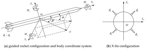
A schematic diagram of the guided rocket configuration and the body coordinate system is shown in Figure 1. The rocket is equipped with four tail control fins arranged in an X-configuration, which generate control moments through differential deflections.
Figure 1.
Guided rocket configuration and control fin layout.
The body coordinate system is defined with the -axis along the longitudinal axis of the rocket, the -axis pointing upward, and the -axis pointing to the right. The relationship between individual fin deflections and the equivalent control inputs can be described in a linear transformation form as:
where , , , and denote the deflections of the four control fins, and , , and denote the equivalent control inputs in the roll, yaw, and pitch channels.
To simplify the calculation and retain the influence of the main motion parameters on aerodynamic forces and moments, this paper still adopts the form of dynamic coefficients to analyze the coupling problem. Considering the convenience to design the control system, characteristic points are selected according to different Mach and altitude in whole flight envelope of the guided rocket, and the aerodynamic force and moment can be obtained after linearization near these characteristic points.
It should be noted that the dominant sources of coupling between attitude channels vary significantly depending on the aerodynamic configuration and control method. Scholars have pointed out that for lateral-symmetric configurations, the rolling moment induced by sideslip angle plays a predominant role [16,17]. In contrast, for spin-stabilized missiles, the primary causes of channel coupling are the Magnus effect and gyroscopic effects [18,19]. For an axial symmetry non-spinning missile, the Magnus and gyroscopic effects can be neglected owing to the low spinning rate [20]. The guided rocket studied in this paper employs an axisymmetric aerodynamic layout, and its angular rates during flight remain relatively small. Consequently, those coupling mechanisms mentioned above are substantially attenuated. Therefore, in this context, the control coupling moments generated by control surface deflections emerge as the principal source of attitude coupling to be considered.
Based on the analysis above, the dynamic model of the guided rocket is established as follows:
where is the angle of attack and is the sideslip angle. and are the roll, yaw, and pitch angular rates, respectively; , , and represent the roll, yaw, and pitch moments of inertia. is the mass and is the velocity of guided rocket. and are respectively the lift force coefficients cause by and . and are respectively the lateral force coefficients cause by and . and are respectively the roll moment coefficients cause by and . and are respectively the yaw moment coefficients cause by and . and are respectively the pitch moment coefficients cause by and .
According to the causes of aerodynamic moment, they can be classified into the following categories, as shown in Table 1.
Table 1.
Classification of Three-channel Aerodynamic Moment.
2.2. The Structure of Autopilot
The control system of the guided rocket is designed as follows: the pitch channel tracks the normal acceleration command, the yaw channel tracks the lateral acceleration command, and the roll channel stabilizes and follows a given roll angle command. To achieve these objectives, a three-loop autopilot with proportional–integral (PI) correction is employed for both the pitch and yaw channels, while a two-loop autopilot with PI-corrected is adopted for the roll channel.
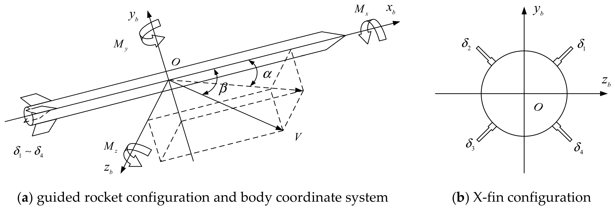
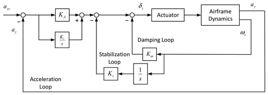
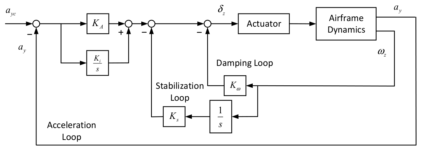
The pitch channel utilizes a three-loop autopilot. As shown in Figure 2, the innermost loop is a pitch angular rate feedback loop that augments damping, the intermediate loop utilizes pitch angle feedback control to enhance the robustness of the missile during its statically unstable phase, and the outermost loop employs normal acceleration feedback control, incorporating a PI corrector to improve the response speed to acceleration command and reduce tracking error. Due to the axisymmetric aerodynamic configuration of the guided rocket studied in this paper, the yaw channel adopts the same autopilot structure as the pitch channel; therefore, its details are not repeated here for brevity.
Figure 2.
Structure of the pitch channel autopilot.
In Figure 2, , , and are the control parameters for the three-loop autopilot. denotes the normal acceleration command and is the measured normal acceleration feedback. represents the deflection command for the pitch channel.
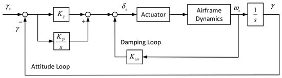
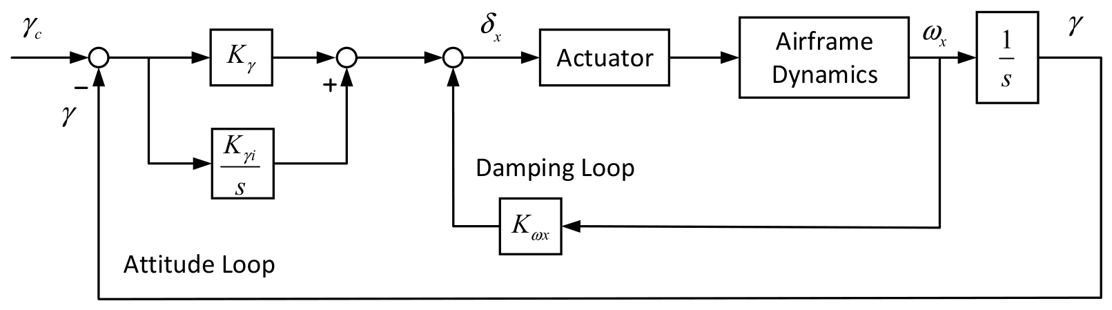
The roll channel utilizes a two-loop autopilot. As shown in Figure 3, the inner loop is a roll rate feedback loop that increases roll damping, and the outer loop uses roll angle feedback with PI correction to reject disturbance aerodynamic moments.
Figure 3.
Structure of the roll channel autopilot.
In Figure 3, , and are the control parameters of the roll channel. denotes the roll angle command and is the roll angle feedback. represents the deflection command for the roll channel.
3. Control Coupling Analysis and Impact
3.1. Control Coupling Analysis
The control coupling of guided rockets mainly refers to the cross-coupling of control moments among the pitch, yaw, and roll channels, which are induced by deflections of the control surfaces. This coupling effect becomes particularly significant during the flight with high angle of attack and high Mach.
Aerodynamic data obtained from computational fluid dynamics (CFD) simulations indicate that severe control cross-coupling between the yaw and roll channels occurs in the guided rocket under the above-mentioned flight conditions. This coupling primarily stems from two physical mechanisms. First, under the high angle of attack conditions, flow separation occurs at the missile’s nose, forming an asymmetric vortex structure. As this vortex system develops along the missile’s rear body, it induces a substantial lateral force, which is directly converted into significant coupled yaw and roll disturbance moments [21,22]. Second, the dynamic pressure differential arises between the windward and leeward sides of the missile under high angle of attack, which will lead to asymmetric aerodynamic loading on the fins and control surfaces. This uneven pressure distribution also contributes additional yawing and rolling moments.
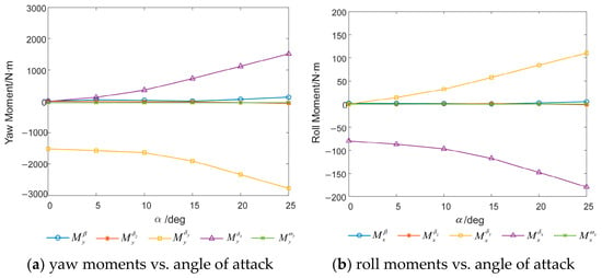
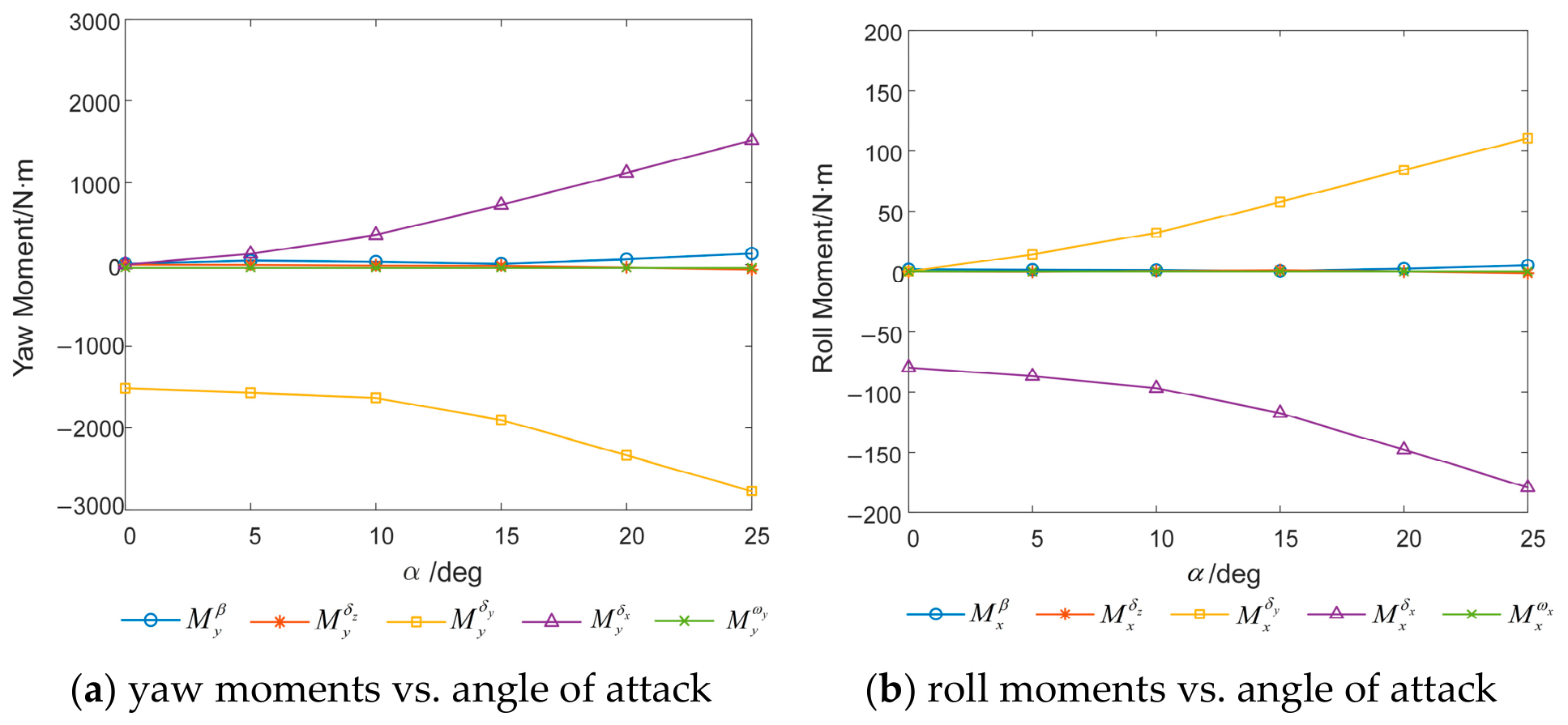
Taking the aerodynamic data at Mach 5 as an example, the sideslip angle is set to 0 deg, and the deflections for the pitch, yaw, and roll channels are all set to 5 deg. The trends of the yaw moment and roll moment components variation with the angle of attack are plotted in Figure 4.
Figure 4.
Trends of yaw moments and roll moments with angle of attack variation.
As shown in Figure 4, both the roll coupling moment acting on the yaw channel and the yaw coupling moment acting on the roll channel increase significantly with the angle of attack. This effect not only compromises the stability of the control system, but also limits the maximum usable angle of attack during high-Mach flight, thereby constraining the maneuverability of the guided rocket. Therefore, to enhance the rocket’s maneuverability and the robustness of control system, a thorough theoretical analysis is essential to quantify the impact of control coupling.
To quantitatively evaluate the coupling intensity between control channels and to provide a basis for subsequent decoupling strategies, this paper proposes the concept of coupling degree. It is specifically defined as the ratio of the coupling moment induced by the control surface deflections of other channels to the primary control moment in a given channel. When the coupling degree is positive, it indicates that the coupling moment is in the same direction as the control moment, enhancing the control effect; When it is negative, it indicates that the coupling moment is opposite to the control moment, weakening the control effect.
For instance, the coupling coefficient from the yaw channel to the roll channel is given by:
where is the control moment of the roll channel itself, and is the coupling moment induced by the yaw deflection. To avoid division by zero, a base moment is introduced, which is set to 1 in this paper.
Based on this definition, the following coupling degree matrix is constructed:
among them, the diagonal elements are zero, indicating no self-coupling within each channel. The off-diagonal elements quantify the cross-coupling between channels: and are the coupling coefficients from the yaw and pitch channels to the roll channel respectively; and are the coupling coefficients from the roll and pitch channels to the yaw channel respectively; and are the coupling coefficients from the roll and yaw channels to the pitch channel respectively.
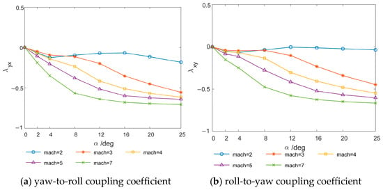
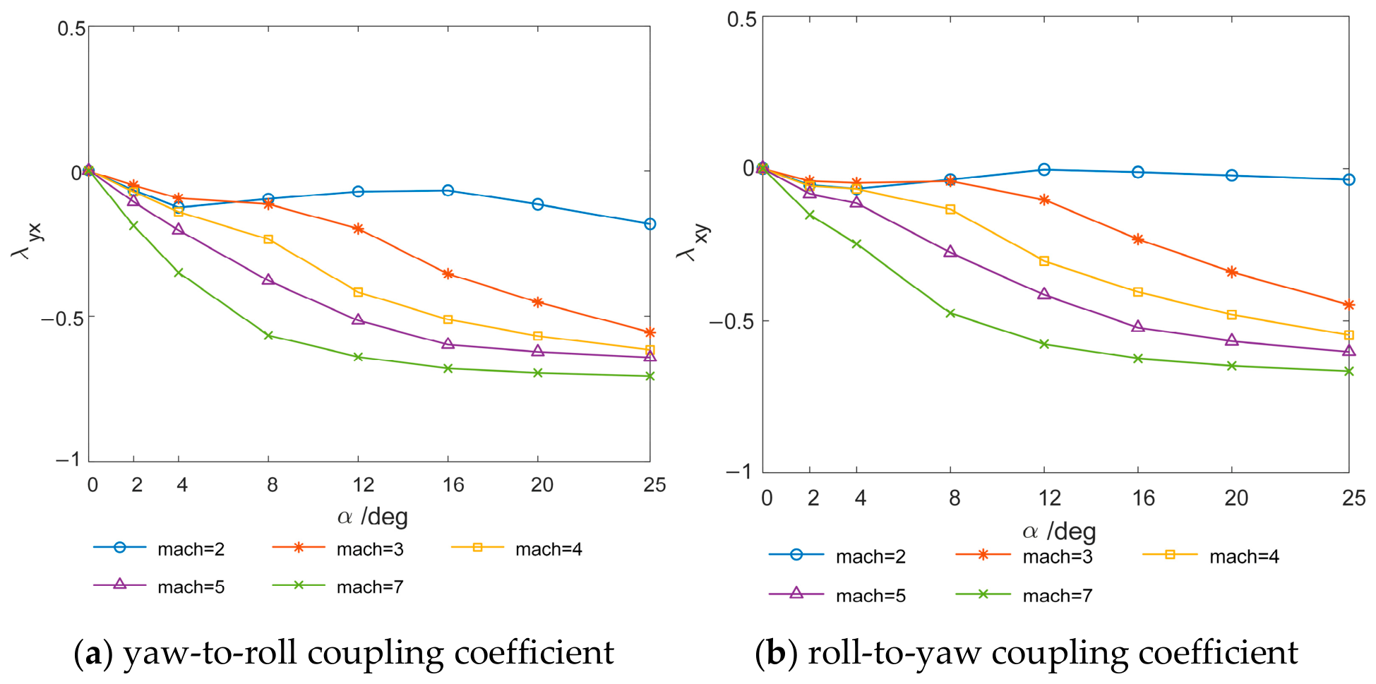
To expand the analysis to the entire flight envelope, the following computational conditions are defined: Mach numbers set as {2, 3, 4, 5, 7}, angles of attack set as {0, 2, 4, 8, 12, 16, 20, 25} deg, with both the yaw and roll deflection angles fixed at 5 deg. Under these conditions, the control coupling characteristics between the yaw and roll channels are presented in Figure 5.
Figure 5.
Coupling coefficients between yaw and roll channels.
From Figure 5, it can be seen that with the angle of attack and Mach increase, the coupling effect between the yaw channel and the roll channel significantly strengthens, especially above Mach 2. The coupling coefficient between the yaw channel and roll channel gradually increases with the angle of attack, and can even reach 70% of the control moment. Figure 4 and Figure 5 present the control coupling characteristics of the guided rocket under high angle-of-attack conditions, which form the basis for the subsequent decoupling control analysis and controller design.
3.2. The Influence of Control Coupling
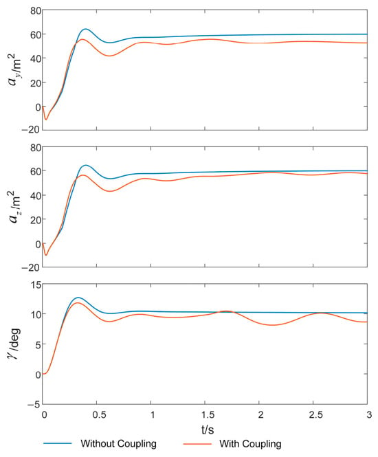
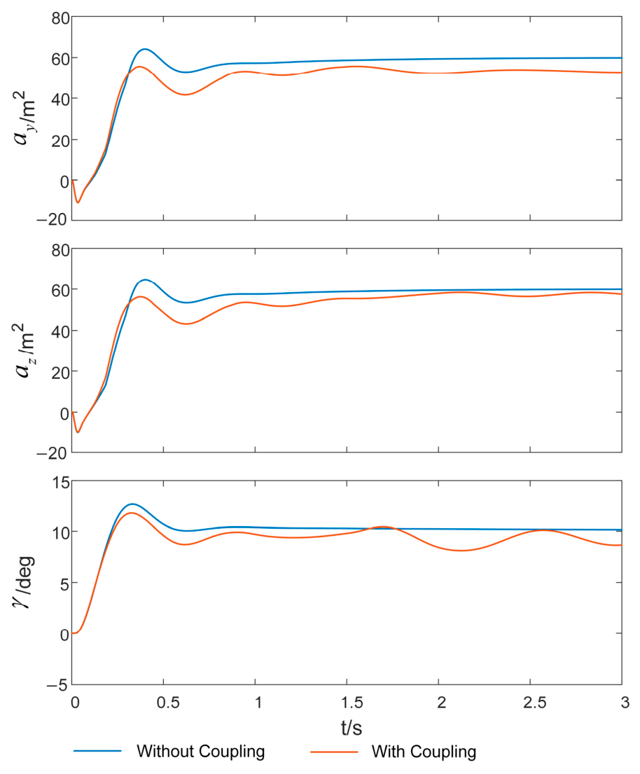
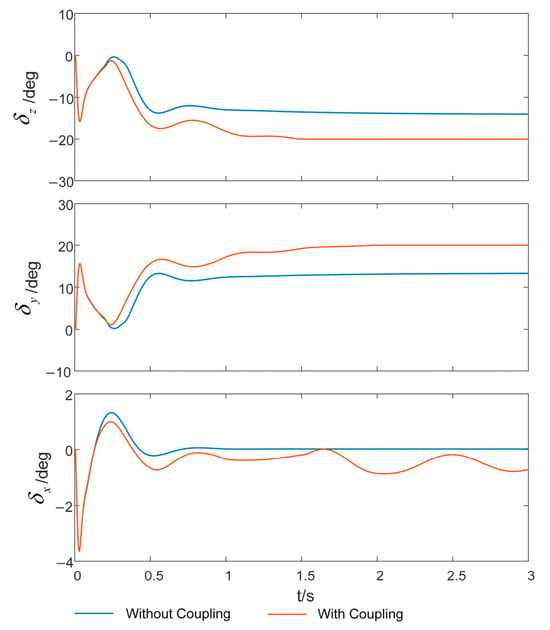
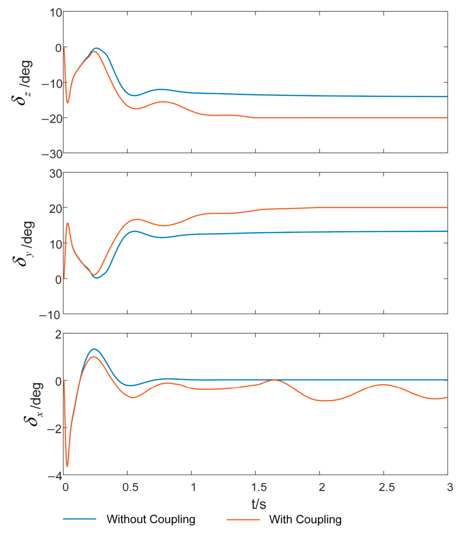
According to the previous analysis, the control coupling among the pitch, yaw, and roll channels can severely degrade the control system performance, and have adverse effects on system stability and command tracking. To illustrate this issue concretely, taking the characteristic points at Mach 5 and an altitude of 20 km as an example, the dynamic response of control coupling to all three channels is compared and analyzed. In this simulation, the normal and lateral acceleration commands for the pitch and yaw channels are set to 50 m/s2, and the roll angle command is set to 10 deg. Figure 6 and Figure 7 compare the command response curves and the deflection response curves for the pitch, yaw, and roll channels under two conditions: with control coupling considered and with it neglected.
Figure 6.
Command response comparison.
Figure 7.
Three-channel deflection angle responses.
From the comparison results of Figure 6 and Figure 7, it can be seen that accounting for control coupling will prolongs the settling time for the pitch and yaw channels. In contrast, the roll channel is more significantly affected, especially when the pitch channel enters steady-state tracking. The underlying reason is that when the pitch channel reaches steady state with an increased angle of attack, the roll channel control coupling intensifies, resulting in a significant decrease in dynamic performance. Furthermore, to achieve the same command tracking effect, the control system must generate larger deflection commands, which not only further exacerbates the coupling effect between channels, but also may cause actuator saturation due to deflection angle requirements exceeding the mechanical limit, thereby threatening the stability and reliability of control system.
4. Design of Adaptive Decoupling Controller
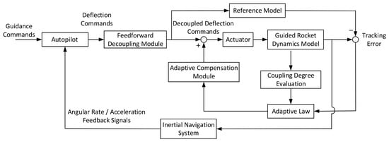
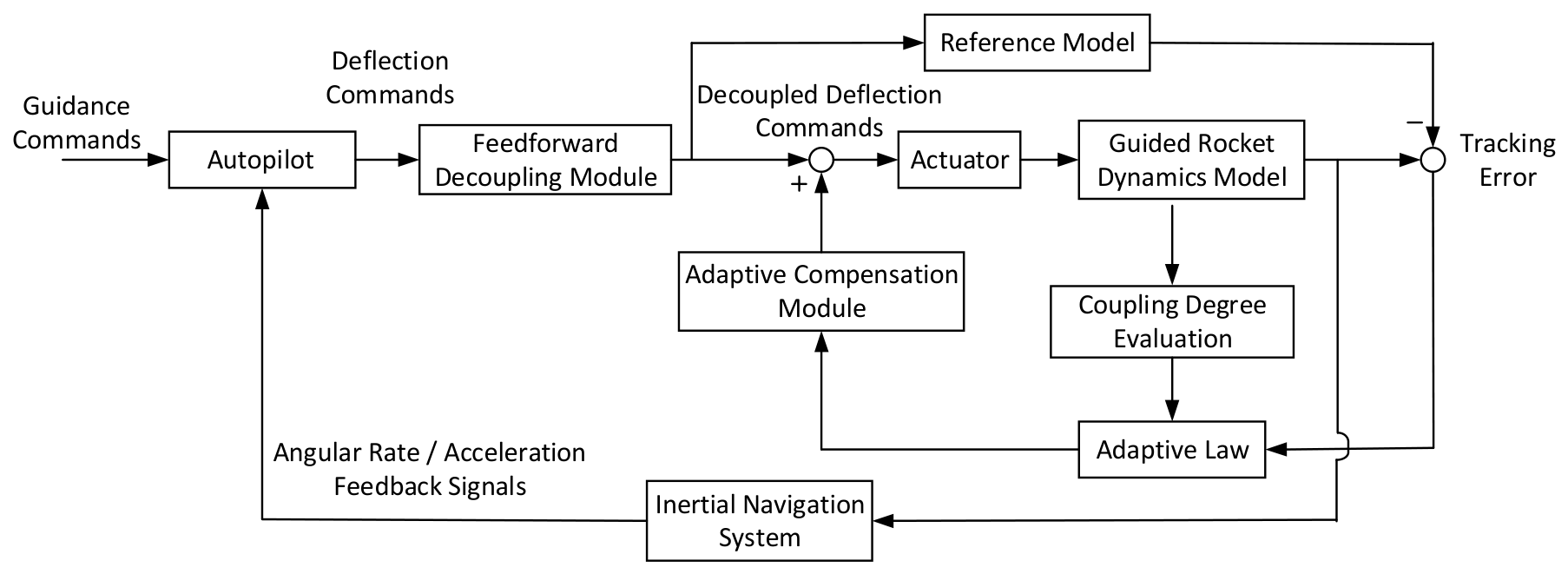
To effectively suppress the coupling moment induced by control surface deflections and to mitigate the impact of aerodynamic parameter uncertainties on decoupling performance during actual flight, this section proposes an adaptive decoupling control architecture based on the coupling intensity. This architecture is constructed in three stages: First, a static decoupling controller based on classical feedforward method is designed to cancel the coupling terms in theoretical aerodynamic model. Subsequently, to cope with the uncertainty of aerodynamic parameters, an online compensation mechanism utilizing MRAC is introduced. Finally, by using the coupling degree matrix as a measure, a variable-gain adaptive law that dynamically adjusts with the strength of control coupling is constructed. The complete framework of the proposed decoupling control system is shown in Figure 8.
Figure 8.
Decoupling Control Structure of Guided Rocket.
4.1. Design of Feedforward Decoupling Controller
The feedforward decoupling controller is designed based on the theoretical aerodynamic data of the guided rocket. The core idea is to introduce a pre-compensation matrix at the autopilot output to cancel the control coupling, make the control system to exhibit approximately decoupled dynamic characteristics.
The design of the feedforward decoupling controller in this section is based on the three-channel autopilot structure established in Section 2.1. To begin, the attitude dynamics part of the guided rocket model from Equation (2) is reformulated into the following form:
Equation (5) reveals significant control coupling among the three attitude channels of guided rocket. To facilitate decoupling design, the compensated deflection angle commands for the roll, yaw, and pitch channels after feedforward decoupling are denoted as , and respectively. Their relationship to the original uncompensated commands is given by:
where are the decoupling coefficients to be designed. Accordingly, the control moment term in Equation (5) can be reformulated as:
To eliminate coupling in the compensated control moments, the off-diagonal elements of its matrix must be set to zero. Solving the coefficients as follows:
With Equations (6) and (8), Equation (5) can be expressed as:
It is important to note that the effectiveness of this feedforward decoupling scheme is highly dependent on the accuracy of aerodynamic parameters. The decoupling coefficient is designed based on theoretical aerodynamic data and updated online by monitoring real-time flight status. However, in practical engineering, due to the differences among the theoretical calculations, wind tunnel tests, and real flight environments, there are inevitably unmodeled errors in aerodynamic data. These underlying errors will directly introduce deviations in the decoupling calculations, impairing the overall decoupling performance of the control system. Therefore, in order to compensate for the errors in aerodynamic data and improve the robustness of decoupling control in control system, it is necessary to introduce an online real-time compensation mechanism based on feedforward decoupling.
4.2. Design of Model Reference Adaptive Compensator
To enhance the robustness of the decoupling system against aerodynamic parameter perturbations, this section proposes an online compensation strategy based on MRAC. This strategy adds an adaptive compensator in parallel to the original static feedforward architecture. At its core, an ideal decoupling reference model is constructed. Then, based on Lyapunov stability theory, a parameter adaptation law ensuring uniformly ultimately bounded tracking performance is derived. By dynamically compensating the feedforward decoupling coefficient, the proposed method enables bounded and smooth tracking of the reference model while effectively suppressing oscillatory coupling dynamics, thereby achieving robust dynamic decoupling performance.
Taking the attitude dynamics model with modeling uncertainties as the controlled plant, Equation (5) is expressed in the standard state-space form:
where is the state vector, is the control input vector, and is the constant term. is the state matrix, and is the control coupling matrix.
Using the feedforward decoupling model based on theoretical aerodynamic data as the ideal reference model. Accordingly, Equation (9) is formulated in state-space form:
where and are the reference state vector and the decoupled reference control input, respectively; (where = ) and are the corresponding system matrix and control decoupling matrix of the reference model.
The control law is defined as:
where is the decoupling matrix designed by the feedforward decoupling controller, while is the dynamic compensation matrix updated online via the adaptation law.
Assume the existence of an ideal gain matrix such that holds. Based on this, the parameter error matrix is defined as:
Define the ideal compensation matrix as .
To design the adaptation law, the tracking error is defined based on Lyapunov theory, and its dynamics are governed by the following error equation:
Substitute the parameter error matrix given in Equation (14):
Select the following Lyapunov function:
where is a symmetric positive definite matrix that satisfies the Lyapunov equation (with ); and is a positive definite adaptation gain matrix. In the proposed scheme, takes the diagonal form:
where the scalar gains are scheduled online according to the coupling intensity (to be detailed in Section 4.3). In the classical MRAC framework, is taken as constant. However, in the proposed control architecture, will be scheduled online as a function of the coupling intensity to balance convergence speed and stability across varying flight conditions. To ensure the subsequent stability analysis remains valid under such scheduling, we impose the following assumption on .
Assumption 1.
The time-varying adaptation gain matrix satisfies:
- (1)
- is positive definite and bounded, i.e., there exist positive constants and such that for all .
- (2)
- is bounded for almost all , i.e., for some finite constant .
These conditions are satisfied by the bounded and piecewise continuously differentiable gain-scheduling function designed in Section 4.3.
Computing the time derivative of along the error dynamics in Equation (16):
Substituting from Equation (16) into the first two terms and using :
Since is a scalar, it equals its transpose . Hence:
Using the trace identity , the full expression for becomes:
To eliminate the term containing , we select the adaptation law:
as defined in Equation (14). Note that the ideal compensation matrix is constant, hence:
Substituting Equation (23) into Equation (22), the trace term involving vanishes, yielding:
The second term captures the effect of the time-varying adaptation gain, which is absent in the classical constant- case. Using the identity , we rewrite Equation (25) as:
Under Assumption 1, and . Therefore, the second term in Equation (25) satisfies the bound:
By the Rayleigh quotient property of the symmetric positive definite matrix , we have , which implies . Consequently,
Under the standard MRAC assumptions with bounded reference input u′ and bounded scheduling gain Γ(t), the adaptive parameter matrix Φ(t) is assumed to remain bounded during system evolution. Therefore, there exists a positive constant such that for all . Thus,
From Equation (29), whenever
Therefore, the proposed adaptive decoupling controller guarantees practical stability of the closed-loop system under bounded gain scheduling.
This inequality establishes that the tracking error and the parameter error are uniformly ultimately bounded (UUB) with ultimate bound on the tracking error.
Remark 1.
When remains constant (i.e., ), the second term in Equation (25) vanishes identically, recovering the classical result . In the proposed control scheme, this situation occurs whenever the coupling intensity remains within a saturation region of the gain-scheduling function, which is the prevalent condition throughout the majority of the flight.
Remark 2.
During transitions between different coupling regimes where Γ(t) varies continuously, the additional term introduced by
(t) may temporarily weaken the negative definiteness of
. However, the above analysis guarantees that both the tracking error e(t) and the parameter error Φ(t) remain uniformly ultimately bounded and remain within a compact neighborhood of the origin after the transient variation in Γ(t).
Based on the Lyapunov stability analysis above, the model reference adaptive control law is derived. This law utilizes the tracking error and the reference command as inputs, and with the adaptation gain matrix as tuning parameter, it updates the compensation matrix online. This achieves dynamic, real-time adaptive compensation for the static feedforward decoupling matrix . Given the difficulty in accurately obtaining real aerodynamic parameters, it is common engineering practice to replace the actual control coupling matrix with the theoretical control coupling matrix for controller design.
4.3. Adaptive Strategy Based on Coupling Intensity
It is noteworthy that the inter-channel coupling intensity of the guided rocket varies with flight conditions. Employing a fixed makes it difficult to balance convergence speed and stability across the entire flight envelope. Therefore, to enhance the overall performance of the adaptive compensator under all operating conditions, it is necessary to design a strategy that can adjust online according to the real-time coupling intensity, enabling fast response under strong coupling and smooth convergence under weak coupling.
As Equation (24) can be decomposed as:
It can be observed that the gain acts as a scaling factor directly on the update law of the compensation parameters and , thereby governing the convergence rate of the roll channel. Similarly, the gains and dictate the update rates of the compensation parameters for the yaw channel and for the pitch channel, respectively, thus regulating the convergence dynamics of their respective channels.
Referring to the coupling degree matrix introduced in Section 3.1, its off-diagonal elements quantitatively describe the inter-channel coupling strength. To establish a direct correspondence with the adaptive gain matrix Γ, the elements of the coupling degree matrix are synthesized into three channel-wise coupling strength indicators:
The specific piecewise linear adjustment function is given as follows:
Although the channel-wise coupling indicators in Equation (32) involve max operators, the resulting gain scheduling function remains piecewise continuously differentiable almost everywhere, which is sufficient for the boundedness analysis presented above.
The gain is scheduled as follows: if , the condition is considered weak coupling, and is set to a lower fixed value ; if , it is considered strong coupling, and is set to a higher fixed value . This strategy enables real-time assessment of the coupling intensity and accordingly adjusts the adaptive gain matrix .
It is important to emphasize that the boundedness of is a structural property of the controller design, rather than a consequence of closed-loop stability. As defined in Equation (33), the gain-scheduling law is constructed with hard, user-defined saturation limits and . Therefore, Γ(t) is mathematically constrained within the interval [, ], independently of the system stability properties.
The boundedness of follows from the structure of the gain-scheduling function. Specifically, the mapping from the coupling indicator to is piecewise linear with finite slope in the transition region, and constant outside this region. Therefore, is a Lipschitz continuous function of with a uniformly bounded rate of variation. It should be noted that the Lyapunov-based stability analysis presented in Section 4.2 does not require explicit bounds on the time derivative of the scheduling variable . Instead, only the structural boundedness of the gain variation induced by the predefined scheduling law is invoked. Accordingly, there exists a positive constant such that for all , which is sufficient for the subsequent stability analysis.
This strategy enables faster adaptive convergence under strong coupling and smoother behavior under weak coupling, thereby achieving optimized decoupling performance across the entire flight envelope while ensuring that the structural boundedness required by the stability proof is always satisfied.
5. Simulation Verification
5.1. Simulation System Construction
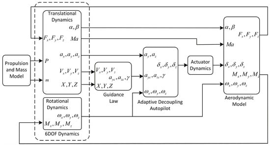
This section establishes an integrated MATLAB/Simulink R2025b (Version 25.2) simulation framework for the guided rocket system. The framework includes the aerodynamic model, translational and rotational dynamics, propulsion and mass variation model, actuator dynamics, guidance law, and the proposed adaptive decoupling autopilot. The signal flow and module interconnections within the framework are detailed in Figure 9.
Figure 9.
Structure Diagram of the Guided Rocket Simulation Framework.
The notation of state variables, control commands, and aerodynamic coefficients follows the definitions established in Section 2.1. The signals , and denote the aerodynamic forces (drag, lift, and lateral force) in the body coordinate system; , and are the corresponding aerodynamic moments (roll, yaw, and pitch moments). and represent the pitch and yaw linear acceleration feedback, respectively, while and denote their commanded values. and are the displacements and velocities expressed in the launch coordinate system. Through closed-loop simulation of the complete flight process, including launch, ascent, and high-altitude maneuvering flight, the effectiveness and robustness of the proposed adaptive decoupling control strategy are systematically evaluated under strong control coupling conditions.
The main physical parameters of the guided rocket used in the simulation are listed in Table 2.
Table 2.
Main physical parameters of the guided rocket.
The servo adopts a second-order dynamic model:
where and denote the natural frequency and damping ratio of the actuator, respectively. corresponding actuator parameters are listed in Table 3.
Table 3.
Parameters of the Servo Actuator.
The parameter design of the adaptive decoupling controller is shown in Table 4.
Table 4.
Parameters of the Adaptive Decoupling Controller.
To rigorously evaluate the effectiveness of the proposed decoupling control strategy, a typical flight trajectory is selected for analysis. Along this trajectory, we choose a characteristic segment with an altitude of 22 km and Mach 5 for in-depth investigation. At this segment, to ensure the required range capability, the rocket must maintain a high angle of attack to sustain its flight path, resulting in severe aerodynamic conditions and significantly intensified control coupling effects. Under such strongly coupled conditions, conventional three-channel independent design proves inadequate. In recent engineering practice, static feedforward decoupling based on aerodynamic data has been widely adopted for coupling mitigation in flight control systems [23,24]. However, this method is highly dependent on the accuracy of the aerodynamic model, and its performance degrades significantly when actual parameters deviate from theoretical values. To address this limitation, this paper proposes a coupling degree-based adaptive decoupling strategy. To evaluate the proposed method, a comparative study of three control strategies—(1) conventional autopilot without decoupling, (2) feedforward decoupling method in [23,24], and (3) the proposed adaptive decoupling method—is conducted under both standard and perturbed aerodynamic conditions.
5.2. Scenario 1: Standard Aerodynamic Data
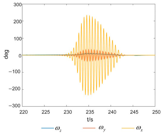
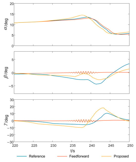
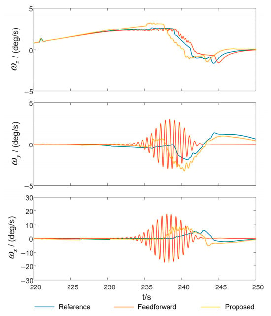
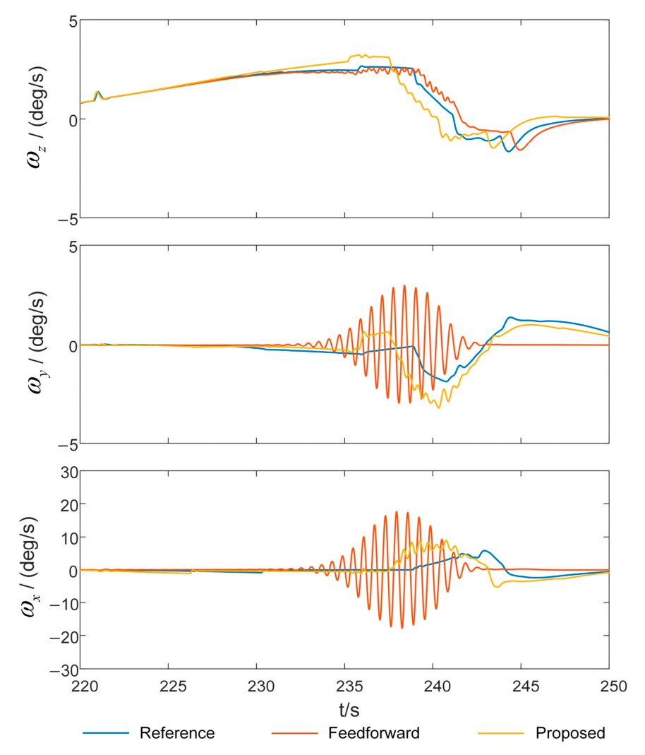
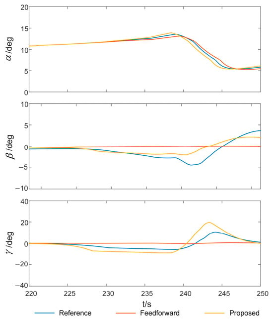
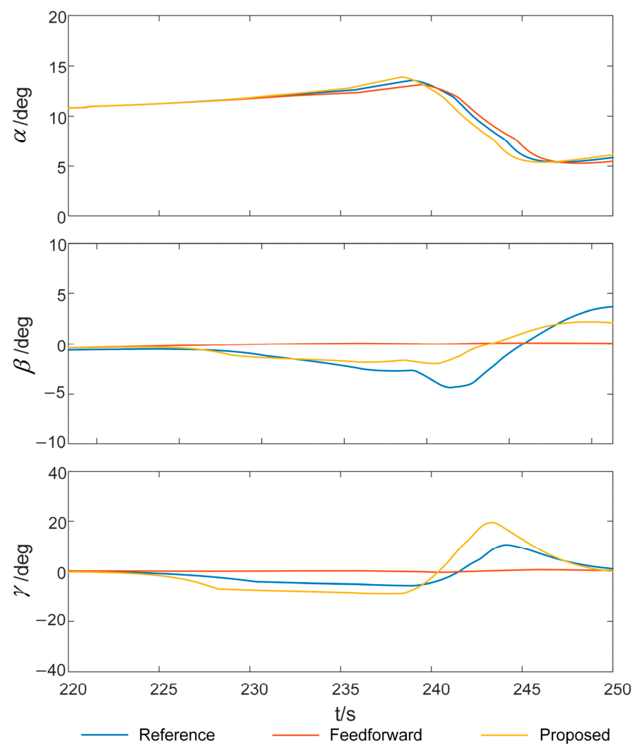
To verify the baseline performance of the proposed decoupling algorithm under standard aerodynamic conditions, this section conducts a comparative simulation experiment based on nominal aerodynamic parameters. The responses of key state variables are organized as follows: the unstable behavior without decoupling is shown separately in Figure 10 and Figure 11, while the comparative tracking performance of the two decoupling methods against the reference model is presented in Figure 12 and Figure 13.
Figure 10.
Attitude angle responses without decoupling.
Figure 11.
Attitude angular rate responses without decoupling.
Figure 12.
Attitude angle responses with standard aerodynamic data.
Figure 13.
Attitude angular rate responses with standard aerodynamic data.
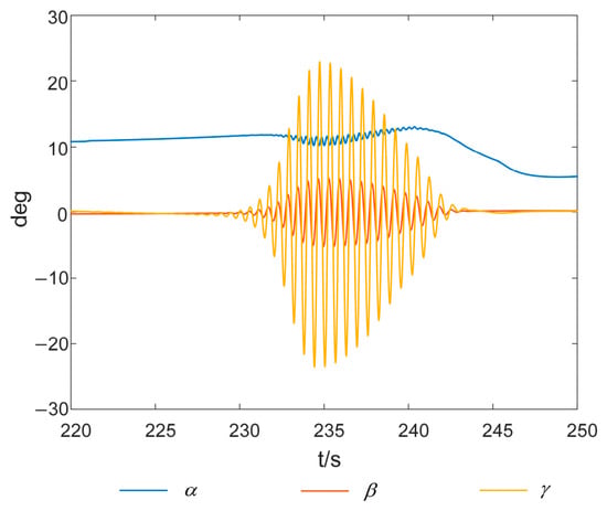
Figure 10 and Figure 11 illustrate the missile attitude angle responses and angular rate responses without decoupling. Under high angle-of-attack maneuvering conditions at the trajectory characteristic point, the angle of attack () gradually increases to 12–13 deg. The three-channel independent autopilot can no longer ensure stability, resulting in severe cross-coupling oscillations: the yaw rate () amplitude reaches ±40 deg/s, and the roll rate () amplitude even attains ±240 deg/s. These responses completely deviate from any acceptable flight envelope, confirming the necessity of decoupling.
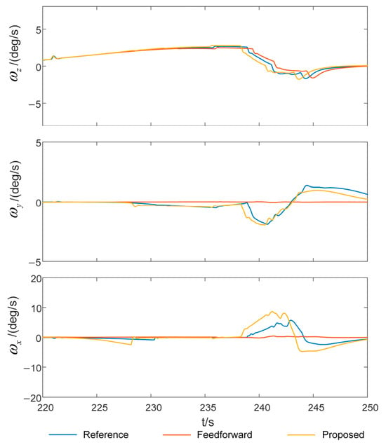
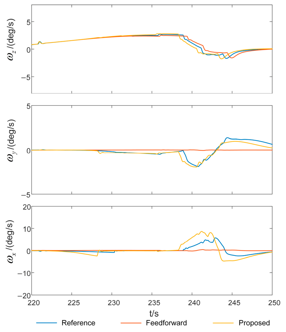
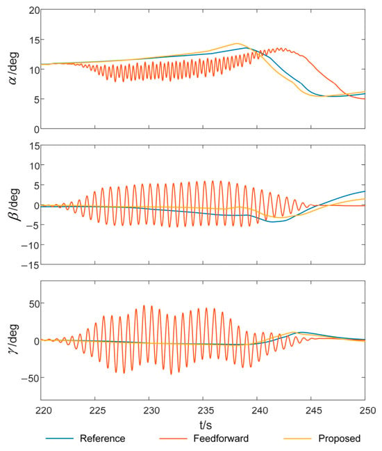
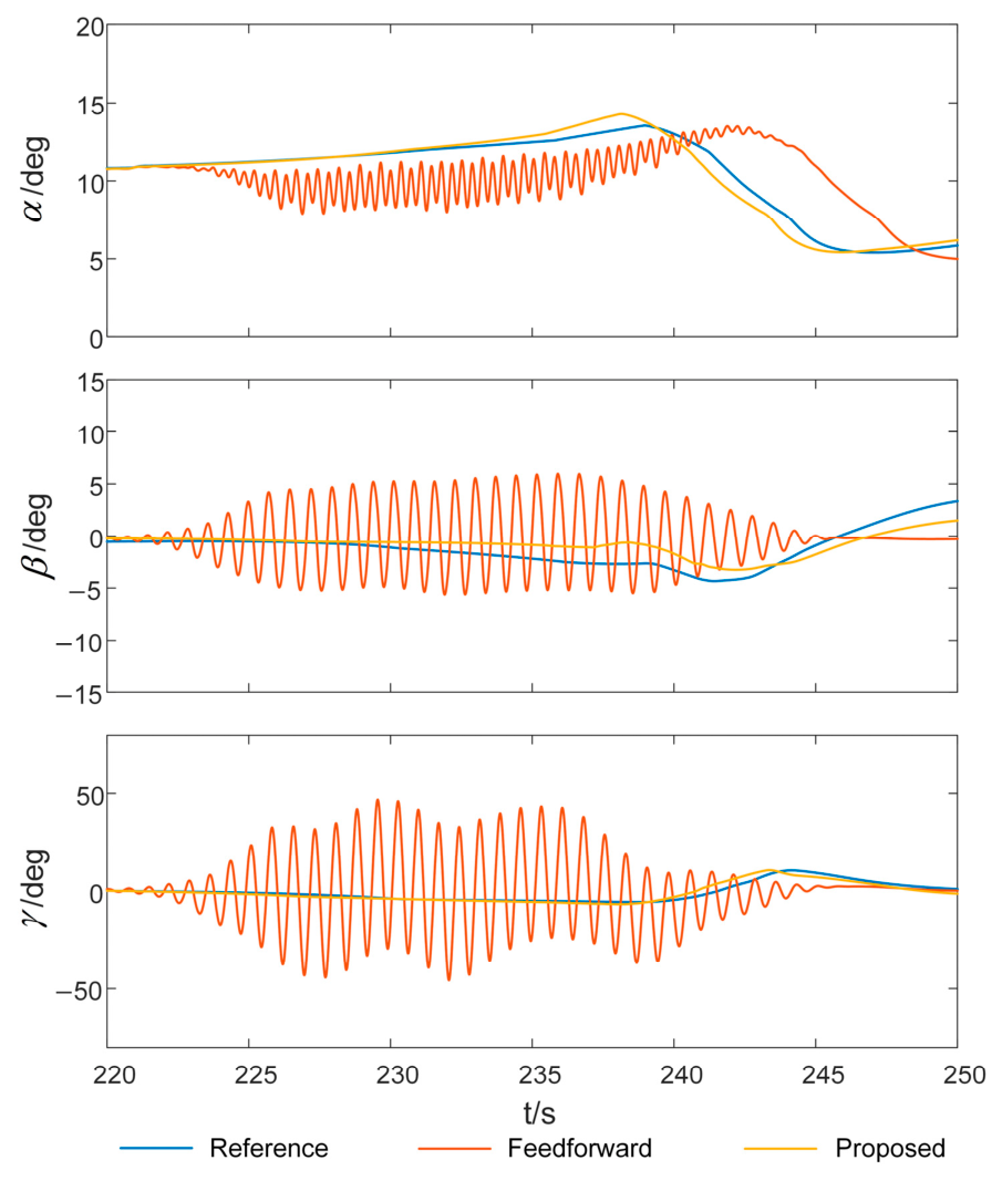
To evaluate the decoupling effectiveness, Figure 12 and Figure 13 compare the responses of the feedforward decoupling strategy and the proposed adaptive method, together with the reference model output that defines the desired dynamic response. Figure 12 shows the attitude angles, and Figure 13 shows the angular rates. Although the feedforward de-coupling strategy can significantly reduce the inter-channel coupling interference, it cannot completely eliminate the residual oscillations. These oscillations exhibit a dominant frequency of approximately 1.8 Hz, with the yaw rate amplitude attenuated to ±3 deg/s while the roll rate amplitude remains at ±20 deg/s. In contrast, the proposed adaptive decoupling method eliminates the underlying coupling oscillation dynamics. The responses in angle of attack, sideslip angle (), and roll angle () exhibit smooth, non-oscillatory transient deviations from the reference model (maximum approximately 1.5° for angle of attack, 2.5° for sideslip angle, and 10° for roll angle), while the 1.8 Hz high-frequency oscillations that plague the feedforward scheme are completely suppressed. As the persistent high-frequency oscillations can excite structural modes, contaminate sensor signals, and ultimately threaten autopilot stability, such slowly varying angular offsets are far less detrimental and entirely acceptable for the autopilot.
5.3. Scenario 2: Coupling Moment Perturbations
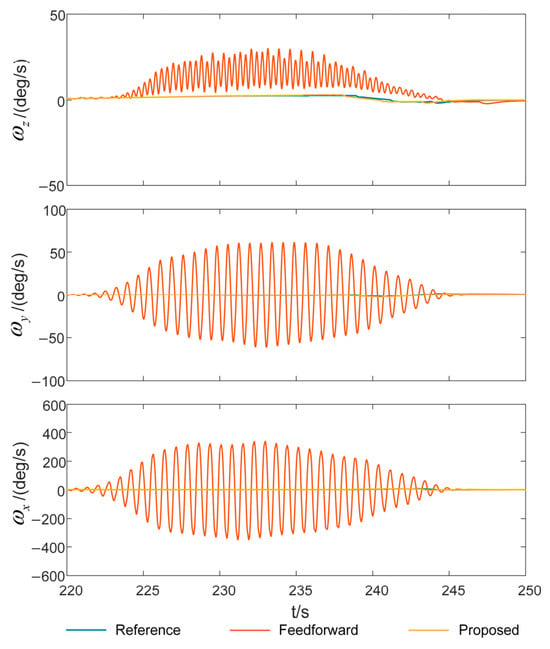
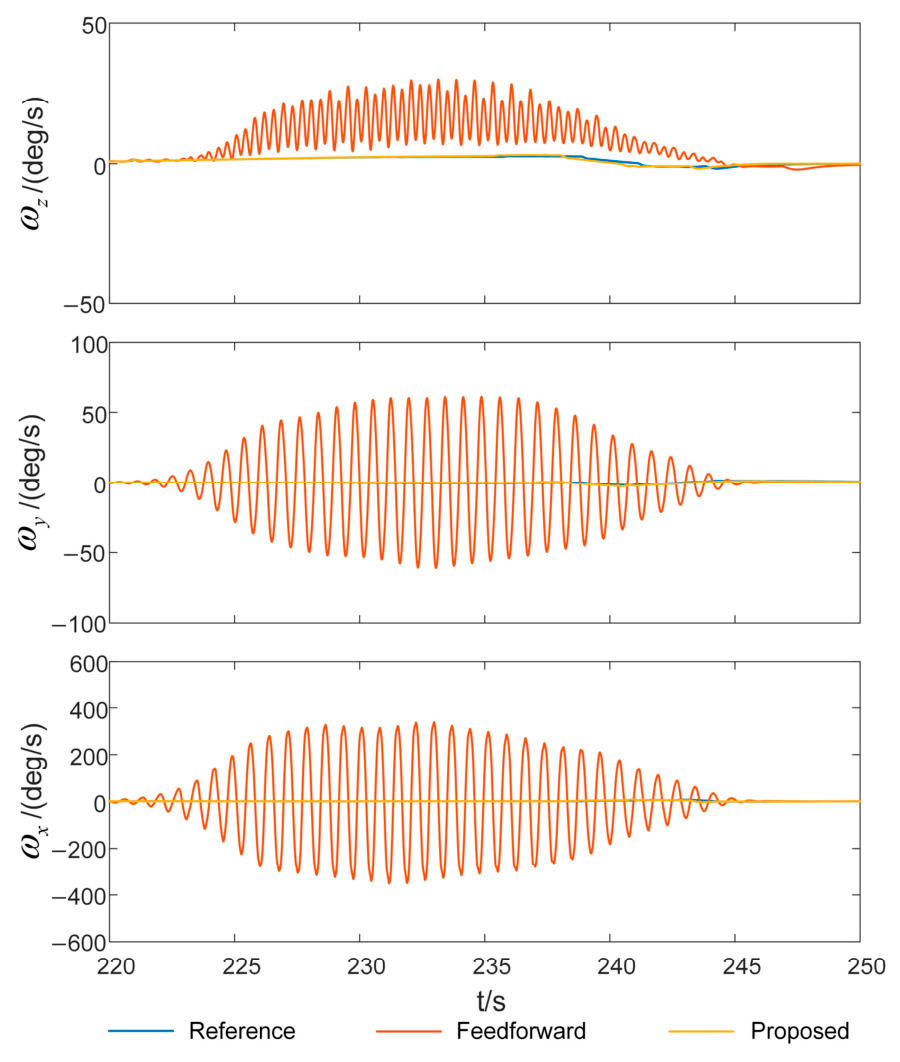
To verify the robustness of the adaptive decoupling controller against perturbations in coupling parameters, this subsection further applies ±50% perturbations to the control coupling moments based on the standard test scenario, and repeats the comparative simulations. The results under −50% coupling perturbation are shown in Figure 14 and Figure 15, and those under +50% coupling perturbation are shown in Figure 16 and Figure 17. In all these figures, the reference model output, the feedforward decoupling response, and the proposed adaptive decoupling response are plotted together for direct comparison.
Figure 14.
Attitude angle responses with −50% coupling perturbation.
Figure 15.
Attitude angular rate responses with −50% coupling perturbation.
Figure 16.
Attitude angle responses with +50% coupling perturbation.
Figure 17.
Attitude angular rate responses with +50% coupling perturbation.
Under −50% coupling perturbation (Figure 14 and Figure 15), the feedforward decoupling method still maintains acceptable tracking, although with slightly increased residual errors compared to the nominal case. This is because the perturbation corresponds to a weakened coupling, and the resulting over-compensation remains within the tolerance of the autopilot’s inherent stability margin. The proposed adaptive method performs similarly well, with its response closely following the reference model.
The situation changes drastically when the coupling is perturbed by +50% (Figure 16 and Figure 17). In this case, the feedforward strategy suffers severe performance degradation due to model mismatch: the under-compensation leads to a rapid accumulation of residual coupling, which not only fails to suppress inter-channel interference but instead exacerbates body oscillations. Specifically, comparing the undecoupled case (Figure 11) with the +50% perturbed case (Figure 17), the yaw rate amplitude under feedforward decoupling increases dramatically from ±8 deg/s (nominal) to ±60 deg/s, the roll rate amplitude increases from ±30 deg/s to ±320 deg/s, and the oscillation duration extends from 14 s to 24 s. This indicates that when the aerodynamic coupling is severely underestimated, the feedforward method can largely lose its effectiveness. In striking contrast, the proposed adaptive decoupling strategy maintains excellent decoupling and control performance under the +50% perturbation through online adaptive compensation, with its response remaining tightly around the reference model in all channels. Moreover, the adaptive method preserves its oscillation-free characteristic, even under severe parameter mismatch, reinforcing the inherent robustness advantage. These results fully demonstrate the exceptional and symmetric robustness of the proposed method against strong parameter uncertainties in both perturbation directions, overcoming the direction-dependent fragility inherent to fixed-gain decoupling approaches.
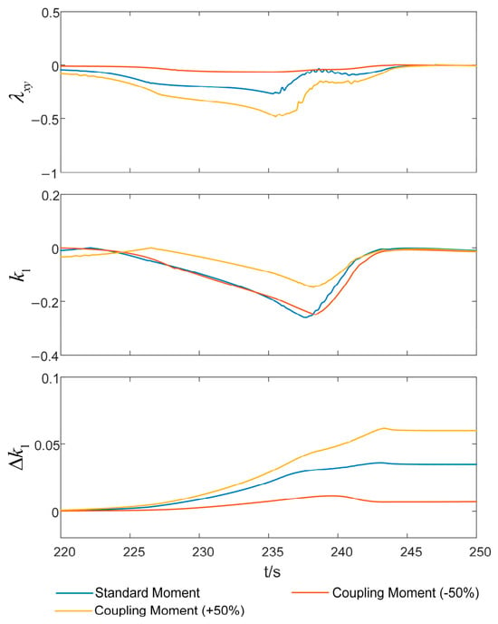
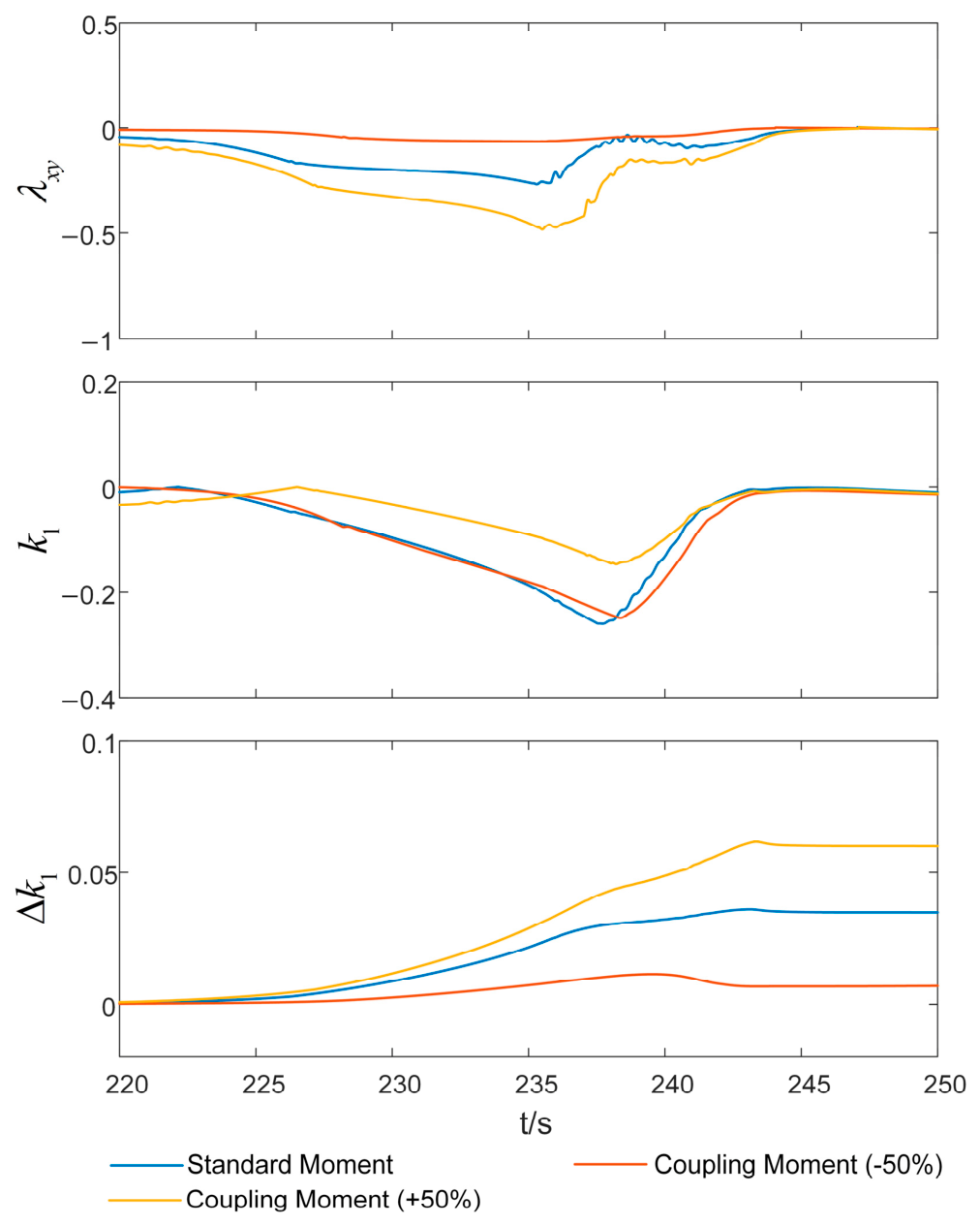
To more intuitively reveal the decoupling mechanism and adaptive characteristics of the proposed method, Figure 18 presents the key parameter curves of the adaptive decoupling control. Taking the relatively severe coupling from the yaw to the roll channel as an example, the three subplots illustrate the evolution trends of the yaw-to-roll channel coupling coefficients , the yaw-to-roll channel feedforward decoupling gain , and the yaw-to-roll channel adaptive compensation gain , respectively.
Figure 18.
Adaptive decoupling controller parameters.
Figure 18 demonstrates that even with substantial ±50% perturbations in the coupling parameters, the dynamic compensation gain can still rapidly track the variations in the coupling degree and adjust online to a new equilibrium value, thereby effectively compensating for parameter disturbances. These curves clearly indicate that the integrated decoupling strategy proposed in this paper forms a “sense–compensate–control” closed loop to address parameter uncertainties by sensing the coupling intensity in real time and dynamically regulating the adaptive compensation amount. This is precisely the core mechanism that enables it to consistently maintain effective decoupling control under varying degrees of disturbance.
Additional simulations under reduced actuator rate limits confirm that the closed-loop system maintains stability and acceptable tracking performance even when temporary actuator saturation occurs.
6. Conclusions
This paper addresses the dual challenges of control coupling among the three channels and the uncertainties in actual aerodynamic parameters for guided rockets. A variable-gain adaptive decoupling control strategy is proposed and validated. Building upon static feedforward decoupling, the strategy innovatively incorporates a reference model adaptive compensation mechanism, effectively overcoming the performance degradation of traditional methods due to parameter perturbations. Furthermore, by introducing the coupling degree as a metric, an adaptation law with real-time gain scheduling based on coupling intensity is designed, accelerating convergence under strong coupling and ensuring stability under weak coupling.
The simulation results demonstrate that, compared to no-decoupling and static decoupling schemes, the proposed strategy effectively suppresses cross-coupling under both nominal and perturbed aerodynamic conditions. It significantly enhances the tracking accuracy, stability, and robustness of the control system in complex flight environments, offering a solution with considerable potential for engineering application to the problem of precision control under demanding flight conditions.
Author Contributions
Conceptualization, C.Z. (Cheng Zhang) and C.Z. (Chenming Zheng); Methodology, C.Z. (Cheng Zhang); Software, J.W.; Validation, J.B., C.Z. (Cheng Zhang) and Z.Z.; Formal Analysis, C.Z. (Chenming Zheng); Investigation, C.Z. (Chenming Zheng) and J.W.; Resources, C.Z. (Cheng Zhang); Data Curation, J.B.; Writing—Original Draft Preparation, C.Z. (Chenming Zheng) and J.W.; Writing—Review & Editing, C.Z. (Chenming Zheng) and Z.Z.; Visualization, J.B.; Supervision, C.Z. (Cheng Zhang); Project Administration, C.Z. (Cheng Zhang); Funding Acquisition, C.Z. (Cheng Zhang). All authors have read and agreed to the published version of the manuscript.
Funding
This research received no external funding.
Data Availability Statement
Data are contained within the article.
Conflicts of Interest
The authors declare no conflicts of interest.
Abbreviations
The following abbreviations are used in this manuscript:
| LQR | Linear Quadratic Regulator |
| CBFs | Control Barrier Functions |
| ESO | Extended State Observer |
| BTT | Bank-To-urn |
| QIGL | Qualitative Indicator-Based Guidance Law |
| IGC | Integrated Guidance and Control |
| MRAC | Model Reference Adaptive Control |
| STT | Skid-To-Turn |
| PI | Proportional–Integral |
| CFD | Computational Fluid Dynamics |
| UUB | Uniformly Ultimately Bounded |
References
- Ghoreyshi, M.; Shumway, N.M.; Aref, P.; Jirasek, A.; Seidel, J. Aerodynamic Characteristics of Circular and Noncircular Cross-Sectional Missile Configurations. J. Spacecr. Rocket. 2024, 61, 630–659. [Google Scholar] [CrossRef] [Scilit]
- Wei, Z.; Long, T.; Shi, R.; Tang, Y.; Li, H. Multidisciplinary Design Optimization of Long-Range Slender Guided Rockets Considering Aeroelasticity and Subsidiary Loads. Aerosp. Sci. Technol. 2019, 92, 790–805. [Google Scholar] [CrossRef] [Scilit]
- Wang, Y.; Xu, M.; An, X.; Xu, Z.; Xu, W.; Quan, E. Numerical Study on the Trajectory of a Long-Range Flexible Rocket with Large Slenderness Ratio. Aerosp. Sci. Technol. 2021, 117, 106959. [Google Scholar] [CrossRef] [Scilit]
- Zhao, M.; Zhang, Y.; Tao, Z.; Liu, Y.; Li, R.; Peng, K. Dynamic Pressure-Based Rocket PID Parameters Adaptive Adjustment Method and Application. J. Phys. Conf. Ser. 2022, 2364, 012048. [Google Scholar] [CrossRef] [Scilit]
- Vincent, R.V.; Economou, J.; Wall, D.G.; Cleminson, J. H∞/LQR Optimal Control for a Supersonic Air-Breathing Missile of Asymmetric Configuration. IFAC-PapersOnLine 2019, 52, 214–218. [Google Scholar] [CrossRef] [Scilit]
- Zhang, J.; Lei, J.; Yin, J.; Niu, J. The Numerical Investigation on the Rolling Decoupling of a Canard-Controlled Missile Using the Jet Control System. Eng. Appl. Comput. Fluid Mech. 2020, 14, 1062–1077. [Google Scholar] [CrossRef] [Scilit]
- Tipàn, S.; Theodoulis, S.; Thai, S.; Proff, M. Nonlinear Dynamic Inversion Flight Control Design for Guided Projectiles. J. Guid. Control Dyn. 2020, 43, 975–980. [Google Scholar] [CrossRef] [Scilit]
- Lian, J.; Zhang, X.; Gautam, C. Decoupling Control for the Actuator Dynamics of Spinning Missiles. Int. J. Aerosp. Eng. 2025, 2025, 6653670. [Google Scholar] [CrossRef] [Scilit]
- Shi, Z.; Liu, Z.; Han, F.; Wang, X. Adaptive Attitude Control for Spinning Projectiles With Time-Varying Aerodynamic Uncertainties. IEEE Trans. Aerosp. Electron. Syst. 2025, 61, 8099–8111. [Google Scholar] [CrossRef] [Scilit]
- Wang, Y.; Yu, J.; Wang, X.; Fang, X. A Guidance and Control Design With Reduced Information for a Dual-Spin Stabilized Projectile. Def. Technol. 2024, 33, 494–505. [Google Scholar] [CrossRef] [Scilit]
- Fan, S.; Wang, J.; Lin, D. Generalized Control Coupling Effect of Spinning Guided Projectiles. IEEE Trans. Aerosp. Electron. Syst. 2022, 58, 4241–4250. [Google Scholar] [CrossRef] [Scilit]
- Ding, Y.; Guo, Z.; Huang, L.; Wang, R.; Cao, S.; Guo, J. Quantitative Coupling Effect Analysis and Rapid Rolling-Tolerant Control for High-Speed Flight Vehicles With Bank-to-Turn Maneuvering. IEEE Trans. Aerosp. Electron. Syst. 2025, 61, 14132–14142. [Google Scholar] [CrossRef] [Scilit]
- Guo, J.; Li, Y.; Zhou, J. Qualitative Indicator-Based Guidance Scheme for Bank-to-Turn Missiles Against Couplings and Maneuvering Targets. Aerosp. Sci. Technol. 2020, 106, 106196. [Google Scholar] [CrossRef] [Scilit]
- Guo, Z.; Yao, L.; Cao, S.; Ding, Y.; Yuan, R.; Huang, L. Integrated Missile Guidance and Control Scheme via Coupling Effect Utilization and Transformation Mechanism. IEEE Trans. Aerosp. Electron. Syst. 2025, 61, 2068–2077. [Google Scholar] [CrossRef] [Scilit]
- Ning, X.; Liang, X.; Wang, Z.; Bai, Y.; Wang, S.; Qiu, L. Fuzzy Adaptive Antidisturbance Control Method for a Class of Lateral Thrust–Aerodynamic Force Composite Hypersonic Flight Vehicles. J. Aerosp. Eng. 2025, 38, 04025019. [Google Scholar] [CrossRef] [Scilit]
- Yang, J.; Wu, C.; Li, S. Distributed Composite Autopilot Design for Bank-to-Turn Missiles With Optimized Tracking Based on Disturbance Observers. Trans. Inst. Meas. Control 2017, 39, 1123–1138. [Google Scholar] [CrossRef] [Scilit]
- Cui, L.; Zhen, Z.; Zhang, K.; Hu, X.; Wang, X. Prescribed-Time Integrated Guidance and Control for Bank to Turn Reentry Vehicle. Aerosp. Sci. Technol. 2024, 150, 109218. [Google Scholar] [CrossRef] [Scilit]
- Dutschke, B.; Mundt, C. Flight Stability of Spinning Projectiles at High Angles of Attack. J. Spacecr. Rocket. 2025, 62, 827–836. [Google Scholar] [CrossRef] [Scilit]
- Yin, J.; Lei, J.; Jiang, S.; Yin, X. The Aerodynamic Characteristics and Its Estimation Method of Finned Missile Experiencing Spin-Deformation Coupling Motion. Aerosp. Sci. Technol. 2021, 115, 106806. [Google Scholar] [CrossRef] [Scilit]
- Rezazadeh Mohammadi, M.; Fathi Jegarkandi, M.; Moarrefianpour, A. Robust Roll Autopilot Design to Reduce Couplings of a Tactical Missile. Aerosp. Sci. Technol. 2016, 51, 142–150. [Google Scholar] [CrossRef] [Scilit]
- Kim, S.-H.; Lee, Y.-I.; Tahk, M.-J. New Structure for an Aerodynamic Fin Control System for Tail Fin-Controlled STT Missiles. J. Aerosp. Eng. 2011, 24, 505–510. [Google Scholar] [CrossRef] [Scilit]
- Wang, Y.; Wang, W.; Ji, Y.; Zhang, J.; Wang, X. Coning Motion Stability and Decoupling Methods Analysis of Spinning Missiles With Angle-of-Attack Feedback Autopilot. Asian J. Control 2023, 25, 1232–1255. [Google Scholar] [CrossRef] [Scilit]
- Ma, W.F.; Wang, P.; Tang, G.J. Research on Aerodynamic Coupling Characteristics and Compensation Control for Hypersonic Vehicle. Tact. Missile Technol. 2017, 4, 32–40. [Google Scholar] [CrossRef]
- Liu, W.; Wei, Z.F.; Cao, H.S. Decoupling Method of Target Missiles Based on Pre-Feedback Compensation. J. Detect. Control 2019, 41, 81–85. [Google Scholar]

Disclaimer/Publisher’s Note: The statements, opinions and data contained in all publications are solely those of the individual author(s) and contributor(s) and not of MDPI and/or the editor(s). MDPI and/or the editor(s) disclaim responsibility for any injury to people or property resulting from any ideas, methods, instructions or products referred to in the content. |
© 2026 by the authors. Licensee MDPI, Basel, Switzerland. This article is an open access article distributed under the terms and conditions of the Creative Commons Attribution (CC BY) license.