


Abstract
Hybrid-electric propulsion and alternative energy carriers are being considered to mitigate the climate impact of short-range regional aviation. Within this framework, the HERA (Hybrid Electric Regional Architecture) project investigates advanced propulsion architectures for a next-generation 72 passenger regional platform. This work presents a cradle-to-grave Life Cycle Assessment of two HERA reference configurations and compares them with a conventional 70 passenger turboprop representative of current service aircraft. The analysis focuses on lithium–sulphur batteries, proton exchange membrane fuel cells, liquid hydrogen storage tanks, and electric motors. The assessment is implemented through a parametric LCA tool supported by a detailed Life Cycle Inventory based on Ecoinvent v3.8 and evaluated using ReCiPe 2016 midpoint indicators. The system boundary includes raw material extraction, manufacturing and assembly, operation under defined mission profiles, maintenance with component replacement, and End-of-Life (EoL) treatment. Results show that the operational phase remains the main driver of climate change impacts, exceeding 95% of total CO2 equivalent emissions across configurations. The battery-based hybrid reduces fuel consumption but increases manufacturing and maintenance burdens. The fuel cell configuration shows a more balanced life cycle profile, with platinum identified as a critical hotspot.
1. Introduction
The aviation sector accounts for approximately 2% of global anthropogenic carbon dioxide (CO2) emissions, in addition to nitrogen oxides (NOx), particulate matter, and noise, which negatively affect air quality and public health in communities located near airports [1]. Although aviation currently accounts for a relatively small share of global greenhouse gas emissions compared to other transport sectors, its projected traffic growth and additional non-CO2 climate effects increase its overall climate impact, making decarbonization a strategic priority [2].
The environmental footprint of aviation extends beyond flight operations and includes raw material extraction, component manufacturing, aircraft assembly, maintenance activities, and EoL treatment. Current production frameworks generate substantial material waste, and only a limited share of aircraft materials is effectively recovered at retirement [1]. These limitations highlight the necessity of adopting a systemic life cycle perspective capable of preventing burden shifting between operational and non-operational phases.
Emission mitigation strategies have focused on incremental improvements in engine efficiency, aerodynamic refinement, and operational optimization, together with the introduction of Sustainable Aviation Fuels (SAFs). However, existing commitments remain insufficient to achieve net-zero energy-related CO2 emissions by 2050 and to limit global temperature increase to 1.5 °C above pre-industrial levels [3]. Meeting these targets requires disruptive technological innovation across propulsion systems, energy carriers, manufacturing processes, and aircraft architectures.
Among the emerging technological pathways, hybrid-electric propulsion systems are considered promising solutions for short- and medium-range aviation [4]. By combining conventional thermal engines with electrically driven powertrains supplied by batteries and/or fuel cells, hybrid architectures enable optimized energy management strategies and potentially lower fuel consumption and emissions. Several research initiatives are currently investigating these configurations for regional aircraft applications. The HERA (Hybrid-Electric Regional Aircraft) project represents one such effort, aiming to develop a 50–100 seat regional aircraft for missions below 500 km, targeting substantial reductions in greenhouse gas emissions through the integration of hybrid-electric technologies and alternative fuels [5].
Within this evolving technological landscape, Life Cycle Assessment (LCA) has become a fundamental methodology for quantifying environmental impacts associated with aeronautical systems throughout their entire life cycle [6]. LCA enables the identification of environmental hotspots, supports comparative technology assessment, and provides quantitative evidence to guide sustainable design choices.
Early cradle-to-grave LCAs of conventional aircraft, such as the assessment of the Airbus A320 conducted by Howe et al. [7], demonstrated the dominant contribution of the operational phase to total environmental impact, while also highlighting the relevant contribution of manufacturing and EoL processes, particularly for composite materials. More recent studies have extended LCA methodologies to hybrid-electric concepts. Scholz et al. [8] showed that the environmental performance of a battery-hybrid-electric passenger aircraft is highly sensitive to assumptions regarding electricity generation mix and battery lifetime. Similarly, Ribeiro et al. [9] emphasized the importance of battery production and charging processes within integrated aircraft design frameworks. Additional research combining LCA with preliminary design tools has demonstrated the potential of second-generation biofuels to significantly reduce life cycle CO2 emissions under specific blending scenarios [10].
Despite these advances, existing LCA applications to hybrid-electric aircraft remain limited in scope. Most studies focus on individual subsystems (e.g., propulsion units or battery packs), emphasize the operational phase, or adopt simplified system boundaries. Comprehensive cradle-to-grave analyses that explicitly include raw material extraction, detailed manufacturing breakdowns, operational use under realistic mission profiles, maintenance requirements, and EoL disposal and recycling scenarios are still scarce, particularly for regional hybrid-electric configurations.
Furthermore, hybrid-electric architectures introduce additional complexity due to the presence of emerging technologies that are not yet mature within the aeronautical sector. Components such as high-energy-density batteries, fuel cells, and high-voltage electrical systems require forward-looking assumptions regarding material composition, manufacturing routes, performance degradation, and recycling processes.
The present study addresses these gaps by performing a comprehensive cradle-to-grave LCA of a hybrid-electric regional aircraft. The system boundary encompasses raw material extraction, energy carrier production (including kerosene fuels, SAFs, liquid hydrogen, and electricity), manufacturing, assembly, operation under defined mission scenarios, maintenance activities, and EoL treatment. Unlike previous assessments, the aircraft is disaggregated at the preliminary design level into systems, subsystems, and major components, with environmental impacts allocated accordingly.
This work represents a continuation and methodological extension of the model previously developed by Vivalda et al. [11], which provided a life cycle framework for conventional aircraft systems. In the present study, the model is expanded to hybrid-electric architectures and alternative fuels, incorporating new technological elements and updated inventory assumptions. Particular attention is devoted to the explicit treatment of key modeling assumptions, recognizing that several components considered in this analysis are not yet fully industrialized within the aeronautical sector.
Through this comprehensive and harmonized approach, the study contributes to a deeper understanding of the environmental trade-offs associated with hybrid-electric aircraft and supports informed decision-making in early-stage aircraft design and long-term decarbonization strategies.
The paper is organized as follows. Section 2 describes the LCA framework implemented in the AliCia tool, including the system boundary, data sources, and impact assessment method and it details the life cycle inventory development for the hybrid-electric propulsion components considered in this study, with specific focus on batteries, fuel cells, liquid hydrogen storage, and electric motors. Section 4 presents the results for the three configurations and the conventional turboprop benchmark and it discusses the main environmental drivers and the associated trade-offs across life cycle phases. Finally, Section 4 summarizes the main conclusions and outlines key implications for early-stage aircraft design.
2. Methodology
The aim of this paper is to extend the parametric LCA methodology currently implemented in the AliCia tool to regional aircraft featuring hybrid-electric and fully electric propulsion architectures [11]. The upgraded framework enables cradle-to-grave assessments across conventional, hybrid-electric, and fully electric configurations. The system boundary includes raw material extraction, manufacturing and assembly, operation under the selected mission scenarios, maintenance activities, and EoL treatment through disposal and/or recycling.
EoL processes are modeled using the recycling and waste treatment datasets available in the Ecoinvent v3.8 database. For metallic structural materials such as aluminium alloys, the datasets include established industrial recycling loops, where a significant share of the material originates from secondary aluminium derived from recycled scrap. Carbon-fiber-reinforced polymers (CFRP), which currently exhibit more limited recycling rates, are assumed to undergo partial recycling (approximately 20%), while the remaining fraction is treated through disposal or energy recovery processes. Materials used in fuel cell systems, including platinum catalysts, are also represented through datasets that account for existing recycling practices due to their high economic value. The disposal stage therefore represents the treatment of the fraction of materials that cannot be recovered through recycling.
The functional unit adopted in this study is the transport of one passenger over the reference regional mission distance considered within the HERA project framework. Three aircraft configurations are analyzed: a 72-passenger conventional turboprop, a 72-passenger battery-hybrid electric aircraft, and an 80-passenger hydrogen-hybrid electric aircraft equipped with a fuel cell system.
Although the analyzed aircraft have different seating capacities, environmental impacts are normalized on a per-passenger basis to ensure comparability across systems. For normalization purposes, a 100% passenger load factor is assumed. All configurations are evaluated under the same reference mission profile representative of short-range regional operations.
The model is supported by a dedicated database based on Ecoinvent v3.8 [12], which includes: (i) main aircraft components and subsystems, (ii) material compositions with representative mass fractions, and (iii) associated manufacturing processes such as automated fiber placement (AFP), autoclave curing, machining, extrusion, and anodizing.
The required input parameters are limited to key early-design variables, including aircraft mass, selected technologies, and mission requirements. This structure enables the integration of environmental assessment within preliminary aircraft design.
The primary methodological enhancement consists of restructuring and expanding the Life Cycle Inventory (LCI), which forms the core of the model. The inventory is extended to include components specific to hybrid-electric propulsion architectures, such as fuel cells, battery systems, electric motors, and liquid hydrogen storage tanks.
Each new component is defined at the subsystem level, with material composition and manufacturing routes derived from the literature and industrial practice. When aerospace-specific data are unavailable, datasets from adjacent sectors, mainly automotive, are used as representative proxies for material production or manufacturing processes. This approach is commonly adopted in early-stage LCA studies of emerging technologies, where detailed aerospace-specific inventories are not yet available.
All inventories are implemented using Ecoinvent datasets [12]. Environmental impacts are calculated using the ReCiPe 2016 method [13], considering 17 midpoint categories. The midpoint approach limits aggregation uncertainty and enables multi-category assessment beyond climate change.
Electricity consumption associated with manufacturing processes and system operation is modeled using the European electricity mix from the Ecoinvent v3.8 database, ensuring consistency with the background datasets used in the life cycle inventory.
The combined use of Ecoinvent and ReCiPe ensures methodological consistency across life cycle phases and allows direct comparison between conventional and hybrid-electric aircraft. Impacts related to climate change, particulate matter formation, acidification, eutrophication, resource use, and toxicity are evaluated within a unified framework, enabling consistent assessment of environmental trade-offs.
2.1. Battery Technologies and Manufacturing Processes
The main limitation of current battery technology is its relatively low energy density, which constrains aircraft range and leads to excessive battery mass [14]. In addition to high specific energy, aeronautical batteries must ensure low structural mass, long cycle life, operational safety, and rechargeability. These requirements are considerably more stringent than those in ground transportation and directly affect both aircraft feasibility and overall environmental performance.
A battery system consists of electrochemical cells assembled into modules and subsequently into a battery pack. Cell production is primarily a chemical process, whereas module and pack manufacturing are mainly mechanical assembly processes.
Two battery chemistries are considered in this study: lithium-ion (Li-ion), representing the current technological baseline, and lithium–sulfur (Li-S), a high-energy-density candidate for future aeronautical applications.
2.1.1. Lithium-Ion Batteries
Li-ion cells typically consist of:
- A cathode based on lithium metal oxides (e.g., LiMn2O4);
- A graphite anode;
- An electrolyte containing lithium salts (e.g., LiPF6) dissolved in organic solvents (EC, DMC);
- A polymer separator (polyethylene or polypropylene).
State-of-the-art Li-ion batteries achieve gravimetric energy densities up to approximately 250 Wh/kg [15]. Although suitable for high-power applications due to their high cell voltage, thermal stability and overheating risks remain critical challenges for aeronautical integration.
The manufacturing process includes slurry preparation, coating onto aluminum (cathode) and copper (anode) current collectors, drying, calendaring, electrode cutting, assembly in controlled dry-room environments, electrolyte filling, sealing, formation cycling, testing, and final module and pack assembly.
The representative material mass distribution adopted in this study is based on published literature data and is summarized in Table 1.
Table 1.
Representative material mass distribution for a Li-ion battery pack [16].
2.1.2. Lithium–Sulfur Batteries
Lithium–sulfur (Li-S) batteries represent a promising alternative due to their theoretical energy density approaching 500 Wh/kg. Sulfur is lightweight, abundant, and non-toxic; however, its low electrical conductivity and limited cycle life remain technological constraints [15].
Li-S cells consist of:
- A sulfur–carbon composite cathode;
- A lithium metal anode;
- An organic electrolyte (e.g., LiTFSI-based);
- A polymer separator (PP or PE).
The manufacturing process follows similar steps to Li-ion batteries, including slurry mixing, coating onto aluminum current collectors, drying, calendaring, electrode cutting, controlled-environment assembly, electrolyte injection, sealing, testing, and modular integration.
The representative material distribution used for the Li-S inventory is reported in Table 2. The cathode constitutes the dominant mass fraction, significantly influencing resource use and environmental impact.
Table 2.
Representative material mass distribution for a Li-S battery cell [17].
2.2. Fuel Cell Technologies and Manufacturing Processes
Current battery technologies exhibit limited specific energy, which directly constrains flight endurance and range. Achieving longer mission duration requires larger battery packs, resulting in substantial mass penalties [18]. For this reason, fuel cells are increasingly considered as an alternative power source to overcome the specific energy limitations of battery-based systems.
Fuel cells (FCs) generate electricity through an electrochemical reaction between hydrogen and oxygen, producing water and heat as by-products. In aeronautical applications, fuel cells represent a promising alternative to battery-only systems due to their higher specific energy potential and continuous power generation capability.
Among the available technologies, Proton Exchange Membrane Fuel Cells (PEMFCs) and Solid Oxide Fuel Cells (SOFCs) are the most relevant for aviation [19].
2.2.1. Proton Exchange Membrane Fuel Cells (PEMFCs)
PEMFC systems operate at relatively low temperatures and employ a polymer electrolyte membrane that allows proton transport while blocking electrons. The core structure consists of:
- A polymer electrolyte membrane (typically perfluorosulfonic acid, e.g., Nafion);
- A platinum-based catalyst layer supported on carbon;
- Gas diffusion layers (GDLs) made of porous carbon;
- Bipolar plates (typically graphite or coated stainless steel);
- Stack housing and auxiliary structural components.
Hydrogen is oxidized at the anode, generating protons and electrons. Protons migrate through the membrane, while electrons flow through an external circuit, producing electrical power. Oxygen is reduced at the cathode, forming water.
The membrane electrode assembly (MEA) is produced through catalyst ink preparation, coating and drying (decal transfer process), followed by hot pressing to ensure adhesion between membrane and electrodes. The gas diffusion layer is manufactured through carbon fiber chopping, paper forming, resin impregnation, and high-temperature graphitization. Bipolar plates are produced via compression molding and bonded to form complete plates before stack assembly [20].
The representative material distribution adopted for PEMFC modeling is summarized in Table 3.
Table 3.
Representative material mass distribution for a PEMFC system [21].
The high proportion of metallic materials, particularly stainless steel used in bipolar plates and structural elements, significantly influences the life cycle environmental profile of PEMFC systems. Although platinum content is limited in mass fraction, its resource criticality and high environmental intensity are relevant for impact assessment.
2.2.2. Solid Oxide Fuel Cells (SOFCs)
SOFC systems operate at high temperatures (700–1000 °C) and use a solid ceramic electrolyte, typically yttria-stabilized zirconia (YSZ), which conducts oxygen ions. The cell architecture consists of:
- A porous nickel–ceramic cermet anode;
- A YSZ electrolyte layer;
- A lanthanum strontium manganite (LSM) cathode;
- Metallic interconnects and structural components.
Due to high operating temperatures, SOFC systems do not require noble metal catalysts such as platinum. However, thermal management and material stability represent critical design challenges.
SOFC components are commonly fabricated using tape casting, where ceramic powders are mixed with polymer binders and plasticizers, cast into thin layers, dried, and sintered. The electrolyte layer is deposited via electrochemical vapor deposition (EVD) or similar high-temperature processes. Cells are subsequently assembled into stacks using metallic interconnects produced through metal forming techniques.
The ceramic-intensive production processes and high-temperature sintering steps contribute substantially to energy demand during manufacturing and are therefore explicitly modeled within the life cycle inventory.
2.3. Liquid Hydrogen Storage Tanks
Hydrogen is an efficient energy carrier for fuel cell systems; however, its storage remains a key technical challenge in aeronautical applications. Liquid hydrogen (LH2) is preferred over gaseous hydrogen due to its higher volumetric energy density. LH2 must be stored at cryogenic conditions (approximately 20 K) in highly insulated tanks. The large temperature gradient between the cryogenic fluid and the ambient environment leads to heat ingress and boil-off losses, requiring advanced thermal insulation solutions.
A representative cryogenic tank architecture is assumed, combining structural and insulation layers. The configuration includes an inner aluminum alloy liner (e.g., Al2219-T8 or Al8090-T8) selected for its favourable mechanical behaviour at cryogenic temperatures, an outer carbon-fiber-reinforced polymer (CFRP) shell to reduce structural mass, a Spray-On Foam Insulation (SOFI) layer to limit conductive and convective heat transfer, and a Multi-Layer Insulation (MLI) system composed of alternating low-emissivity reflective foils and low-conductivity spacers under high vacuum conditions.
The inner liner is manufactured through conventional aluminium alloy processing routes, including bauxite refining (Bayer process), electrolytic reduction (Hall–Héroult process), semi-continuous casting, rolling, heat treatment (solutionizing, quenching, artificial aging), sheet forming, and precision welding. Variable polarity plasma arc welding (VPPA) is adopted to ensure structural integrity in cryogenic service.
The CFRP outer shell is produced by filament winding followed by autoclave curing to achieve high mechanical performance and dimensional stability. Insulation layers are subsequently applied, with SOFI sprayed onto the structural surface and the MLI system installed under controlled vacuum conditions.
The representative material distribution adopted for the liquid hydrogen tank is reported in Table 4.
Table 4.
Representative material mass distribution for a liquid hydrogen storage tank.
2.4. Electric Motors
Electric motors convert electrical energy supplied by batteries or fuel cells into mechanical power. In hybrid-electric aircraft, permanent magnet synchronous motors (PMSMs) represent the current reference architecture due to their high power density, torque capability, and efficiency. Aviation-oriented PMSM units for regional applications typically operate in the 500–2000 kW range. Although high-temperature superconducting (HTS) machines are under investigation for future large-scale platforms, PMSM technology is adopted here for environmental modeling.
Permanent Magnet Synchronous Motors (PMSMs)
A PMSM consists of a rotor equipped with permanent magnets, a stator composed of laminated electrical steel sheets with copper windings, an aluminum housing, and a steel shaft for torque transmission. Mechanical torque is generated by the interaction between the magnetic field of the rotor magnets and the stator windings supplied with alternating current [22].
Sintered NdFeB (neodymium–iron–boron) magnets are widely used due to their high magnetic energy density. The alloy primarily consists of iron, rare earth elements (Nd, Dy), boron, and minor cobalt additions for thermal and corrosion stability. Production follows a powder metallurgy route including vacuum alloy melting, hydrogen decrepitation, fine milling, magnetic alignment, compaction, sintering, annealing, coating, and final magnetization.
The representative magnet composition adopted in this study is reported in Table 5.
Table 5.
Representative composition of NdFeB permanent magnets [23].
The motor housing is typically produced from aluminium alloy by die casting followed by machining, while rotor and stator cores are manufactured from silicon-alloyed electrical steel through rolling, annealing, stamping, and lamination stacking. Copper windings are inserted into insulated stator slots.
The shaft is manufactured from hardened steel through casting, heat treatment, and machining.
The representative material distribution adopted for PMSM modeling is summarized in Table 6.
Table 6.
Representative material distribution for a PMSM electric motor [23].
3. Results and Discussion
The Life Cycle Assessment (LCA) was conducted on two preliminary reference configurations developed within the HERA project framework, representing 72- and 80-passenger regional aircraft concepts. At the current stage, both configurations are not yet frozen in terms of detailed design; consequently, the present assessment is based on the initial technology assumptions and architectural definitions available at the conceptual level. The objective of this analysis is therefore twofold: (i) to quantify the environmental implications associated with the proposed hybrid-electric solutions, and (ii) to provide early-stage feedback to support subsequent design refinement.
The two configurations, hereafter referred to as battery-hybrid and hydrogen-hybrid, were benchmarked against a conventional 72-passenger twin-engine turboprop aircraft (Standard TP).
The battery-hybrid configuration adopts a partial hybrid-electric architecture in which approximately 30% of the required propulsive power is supplied by a lithium-sulphur battery-driven electric powertrain, integrated with a conventional thermal propulsion unit. While the primary airframe structure remains largely metallic, the design incorporates an increased fraction of composite materials relative to the reference aircraft, alongside a higher degree of subsystem electrification.
The hydrogen-hybrid configuration is based on a proton exchange membrane (PEM) fuel cell system powered by liquid hydrogen (LH2), complemented by lithium-sulphur batteries that provide approximately 30% of the total propulsive power through an electric drivetrain. This concept features distributed electric propulsion, extensive onboard electrification, and a composite-intensive structural layout aimed at mitigating mass penalties associated with hydrogen storage and fuel cell integration [5].
The comparative LCA results discussed in the following sections reflect these architectural differences and quantify their influence across the considered life cycle phases.
3.1. Standard Turboprop
The reference configuration considered in this study is a 70-passenger twin-engine turboprop aircraft broadly representative of the ATR 72-600 class. The airframe is primarily aluminum-based, while the wing structure incorporates approximately 70% carbon-fiber-reinforced polymer (CFRP). Propulsion is provided by a conventional thermal powerplant based on turboprop engines.
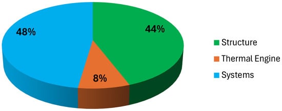
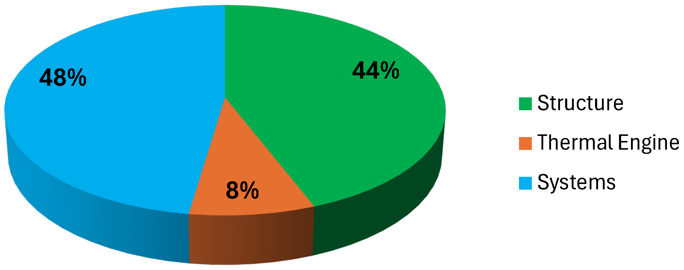
As shown in Figure 1, during the production phase, the largest contributions to Global Warming Potential (GWP) originate from the primary structure (fuselage and wing) and the aircraft systems. Although CFRP components provide structural weight reductions, they are associated with relatively high embodied energy due to energy-intensive carbon fiber manufacturing and autoclave curing processes [24].
Figure 1.
Global Warming Potential (GWP) distribution during the production phase for the Standard Turboprop configuration.
The propulsion system impact is largely driven by the use of nickel-based superalloys and the metallurgical processes required for turbine components [25]. Aircraft systems—especially electrical, avionics, environmental control, and flight control systems—also contribute significantly to the total impact. In particular, electrical systems represent a major contribution due to the presence of generators, batteries, power electronics, and extensive copper wiring [26].
Avionics and environmental control systems (ECSs) further increase the environmental burden because of their electronic assemblies and metallic components.
Maintenance assumptions include periodic replacement of tires (every 250 flights), wheels and brakes (every 2500 flights), batteries and hydraulic oil (every 2500 flight hours), and major engine and avionics overhauls corresponding to approximately 120% of nominal service life. While maintenance impacts broadly follow the trends observed in the production phase, components with shorter replacement intervals, such as wheels and tires, become more relevant over the aircraft operational lifetime.
At the aircraft level, the operational phase dominates the overall life cycle impact, accounting for more than 99% of total CO2-equivalent emissions. The adoption of Sustainable Aviation Fuels (SAFs) can provide moderate reductions compared to conventional kerosene [27]. In the scenarios analyzed, HEFA achieves an approximate 13.3% reduction in life cycle emissions, while ATJ provides a reduction of about 21.1%, outperforming HEFA by roughly 9%. Nevertheless, incremental fuel substitution alone appears insufficient to achieve substantial long-term decarbonization, reinforcing the potential importance of hybrid-electric or fully electric propulsion architectures. In the present study, SAF production pathways were modelled using data derived from literature sources, since dedicated SAF datasets are currently not available in the Ecoinvent v3.8 database. The environmental inventory for HEFA and ATJ fuels was therefore based on published life cycle studies, while background processes such as energy supply were modelled using Ecoinvent datasets.
3.2. Battery-Hybrid Configuration
The battery-hybrid configuration considered in this study adopts a hybridization level of approximately 30%, with the electric powertrain providing about 30% of the total propulsive power. The electric branch remains active throughout the mission in order to reduce kerosene consumption. During cruise, the thermal engine operates at reduced load, while higher thermal power fractions are required during take-off and climb. A dedicated energy reserve is maintained to ensure operational redundancy in emergency conditions.
The aircraft geometry has been aerodynamically refined to improve the lift-to-drag ratio and reduce mission fuel consumption. In parallel, the thermal propulsion system benefits from incremental technological improvements, including advanced materials and an increased turbine inlet temperature, leading to improved specific fuel consumption. Despite these refinements, the overall structural material distribution remains broadly comparable to the reference Standard TP configuration.
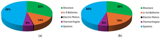
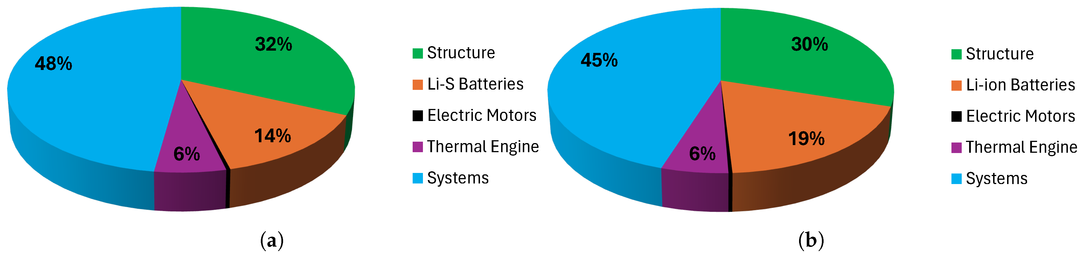
Figure 2 illustrates the distribution of Global Warming Potential (GWP) across subsystems during the production phase. Systems and primary structures represent the dominant contributors to manufacturing-related emissions, for reasons similar to those observed in the conventional turboprop configuration (Standard TP). In the hydrogen–hybrid aircraft, however, the electrical propulsion system has a higher mass and therefore results in a greater environmental impact. The battery system constitutes the most significant non-structural contributor, accounting for approximately 14% of total production-phase CO2-equivalent emissions in the lithium–sulphur configuration and 19% in the lithium-ion configuration.
Figure 2.
Comparison between battery technologies: (a) lithium–sulphur battery configuration, (b) lithium-ion battery configuration.
Overall, production-phase emissions increase by approximately 15% relative to the conventional configuration, as reported in Table 7. This increase is primarily associated with the manufacturing impacts of the battery system and electrical system.
Table 7.
Comparison of life cycle GWP between Standard TP and battery-hybrid configurations.
Beyond climate change, the battery subsystem significantly affects several ReCiPe midpoint categories, including terrestrial and freshwater ecotoxicity, mineral resource scarcity, and fine particulate matter formation. These impacts are mainly associated with upstream processes such as lithium extraction and refining, cathode precursor synthesis, electrolyte production, and the manufacture of organic solvents and conductive additives [28].
Maintenance-related impacts are largely driven by battery replacement. In the present case study, the maintenance phase therefore contributes more significantly to the overall life cycle impacts than in the conventional aircraft configuration. This effect is primarily associated with the substantial mass of the battery system and its relatively short replacement interval, estimated at approximately 1500 flight cycles [29]. For typical aircraft utilization rates, this corresponds to approximately one battery replacement per year.
To mitigate degradation and extend service life, battery operation is limited to a nominal depth of discharge of approximately 20%. Furthermore, the battery pack is assumed to operate within a controlled thermal management envelope, maintaining cell temperatures between 20–40 °C [30], which corresponds to the typical optimal operating range for lithium-based battery systems.
As a consequence, maintenance-related CO2-equivalent emissions are significantly higher than those of the conventional aircraft configuration. In contrast, electric motors and power electronics contribute only marginally to the overall impacts owing to their long service life and relatively low mass.
To evaluate the robustness of this assumption, a sensitivity analysis was performed considering alternative battery lifetimes. In addition to the baseline value, two extended lifetime scenarios were analyzed (2000 and 3000 flight cycles), representing potential improvements achievable through optimized operational strategies, reduced depth of discharge, and advances in battery technology. The scenarios considered are summarized in Table 8.
Table 8.
Battery lifetime scenarios considered in the sensitivity analysis.
As expected, increasing battery lifetime leads to a significant reduction in maintenance-related impacts. Extending the replacement interval from 1500 to 3000 flight cycles reduces the GWP associated with battery replacement by approximately 50%, while the total maintenance-related impact of the aircraft decreases by about 10%.
The disposal phase has a comparatively minor contribution to the overall life cycle impacts. The disposal operations include aircraft disassembly, separation of major structural materials, treatment of hazardous fluids, and recycling of metallic components. In the battery-hybrid configuration, additional processes are required for battery pack removal and dedicated recycling or disposal pathways. Nevertheless, due to the relatively small mass fraction involved and the high recyclability of structural metals such as aluminium, the environmental burden associated with the disposal stage remains limited compared with the operational phase.
Despite the higher impacts observed during production and maintenance, total life cycle CO2 emissions remain largely dominated by the operational stage. The continuous electric contribution to propulsion, combined with aerodynamic improvements and enhanced thermal engine efficiency, leads to a reduction in operational fuel consumption relative to the baseline configuration, partially offsetting the additional environmental burdens associated with earlier life cycle stages.
3.3. Hydrogen-Hybrid Configuration
The hydrogen-hybrid configuration is designed for an 80-passenger aircraft and relies on a fuel cell-based propulsion architecture. The powertrain integrates a proton exchange membrane fuel cell (PEMFC) system supplied by liquid hydrogen (LH2), combined with two battery packs. In contrast to the battery-hybrid configuration, the batteries are not downsized and can deliver up to 750 kW per side. However, they are not intended to provide continuous hybrid support during cruise. Instead, their operation is limited to ground taxi and emergency power supply. Peak power during take-off and climb is primarily delivered by the fuel cell system.
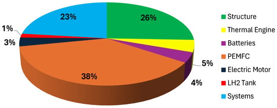
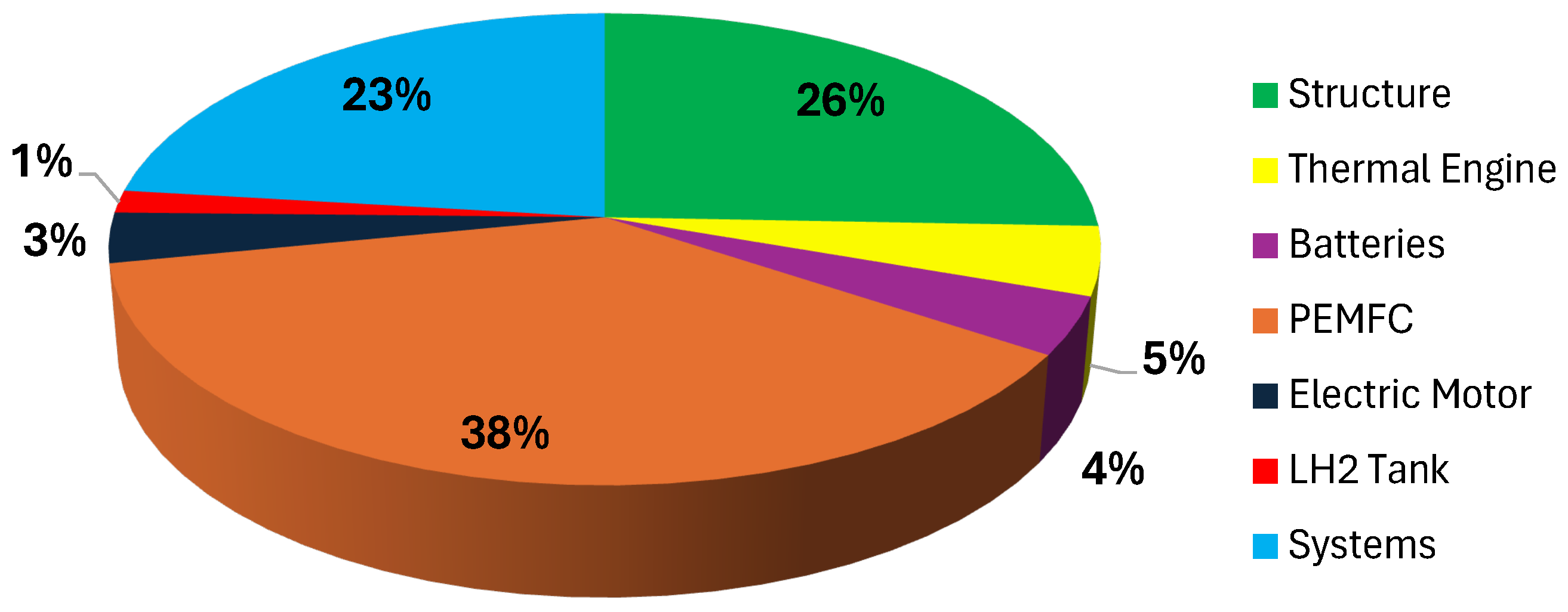
Figure 3 illustrates the distribution of Global Warming Potential (GWP) across subsystems during the production phase. The PEMFC system represents the dominant contributor, accounting for approximately 38% of total manufacturing-related impacts, followed by the airframe structure and aircraft systems.
Figure 3.
Global Warming Potential (kg CO2 eq) during the production phase for the hydrogen-hybrid configuration.
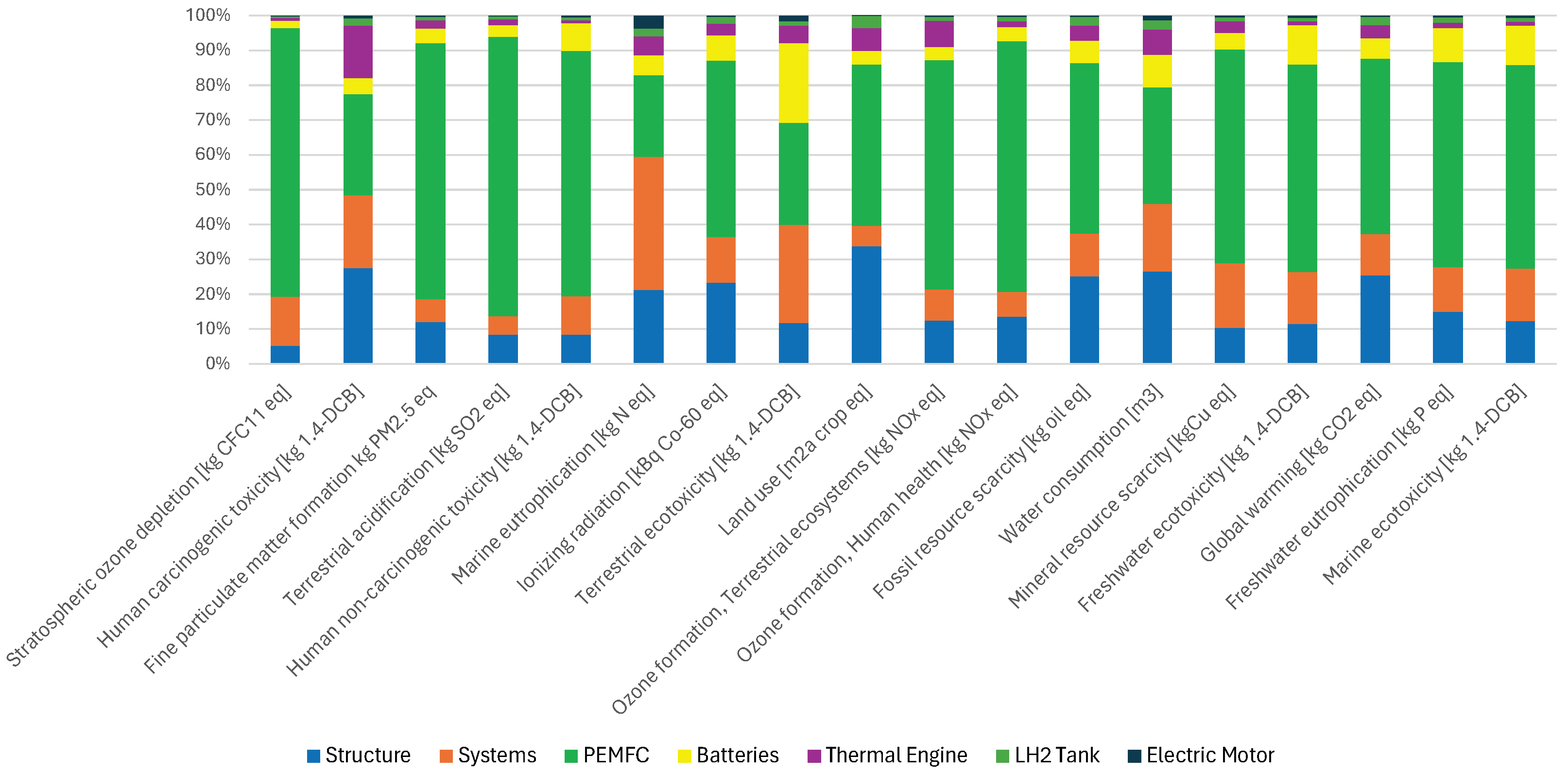
The analysis of the 17 ReCiPe midpoint categories (Figure 4) identifies the fuel cell stack as a major environmental hotspot, particularly in resource scarcity and toxicity-related indicators. This effect is largely associated with the presence of platinum, which acts as a catalyst for hydrogen oxidation and oxygen reduction reactions within the PEMFC. Although platinum accounts for only about 0.1% of the total stack mass, it dominates several impact categories due to the high energy demand and environmental burden associated with its extraction and refining. In addition, more than 70% of global platinum production is concentrated in South Africa, raising concerns regarding supply-chain vulnerability. The use of recycled platinum represents a promising mitigation strategy, with reported reductions in CO2 emissions of up to 54% compared with primary production [21].
Figure 4.
ReCiPe midpoint results for the hydrogen-hybrid configuration across 17 impact categories.
Batteries and electrical subsystems mainly affect human toxicity and ecotoxicity indicators, while electric motors and turboprop assemblies contribute comparatively little to the overall environmental profile. The airframe structure remains a significant contributor to production-phase impacts, largely due to the embodied energy associated with aluminium processing and composite material manufacturing.
From an operational perspective, the hydrogen-hybrid configuration achieves an approximate 36% reduction in CO2 emissions relative to the conventional turboprop baseline, as reported in Table 9. This improvement is primarily driven by the absence of direct carbon emissions associated with LH2 utilization, the higher efficiency of the electric propulsion chain, and the partial use of Sustainable Aviation Fuels (SAFs) during operating conditions in which the thermal propulsion system contributes to thrust.
Table 9.
GWP by life cycle phase for the hydrogen-hybrid configuration (kg CO2 eq).
In the maintenance phase, the replacement of the fuel cell stack constitutes the dominant contribution to the environmental impacts of the hydrogen-hybrid configuration. Fuel cell systems are known to experience a gradual decline in performance during long-term operation. This degradation is driven by several mechanisms, including catalyst loss, electrode material degradation, mechanical damage to the membrane electrode assembly, and variations in operating conditions. As a consequence, the efficiency and output power of the fuel cell system progressively decrease, ultimately requiring stack replacement and leading to increased maintenance requirements [31].
Fuel cell durability is also strongly influenced by operating temperature and local catalyst degradation phenomena. In particular, localized regions of high catalytic activity, often referred to as platinum hotspots, can accelerate degradation processes and reduce stack lifetime under certain operating conditions. Recent studies have proposed adaptive health-state assessment approaches to improve durability prediction of fuel cell systems under varying thermal conditions. For example, the framework proposed by [32] integrates operating temperature effects and degradation behaviour to estimate fuel cell health state over time. Such approaches may improve the accuracy of durability prediction and therefore reduce uncertainty in maintenance modelling within LCA studies.
Based on current technological assumptions, a baseline stack replacement interval of 15,000 operating hours was considered in this study. However, the durability of aeronautical fuel cell systems remains uncertain and is expected to improve in the coming years. In particular, the Clean Hydrogen SRIA roadmap identifies a target durability of up to 30,000 operating hours for future fuel cell modules [33]. For this reason, a sensitivity analysis was performed by varying the stack replacement interval in order to evaluate its influence on maintenance-related impacts.
The results indicate that increasing the stack lifetime significantly reduces the environmental burden associated with maintenance activities, as fewer stack replacements are required over the aircraft operational lifetime. As shown in Table 10, extending the durability from 10,000 to 30,000 operating hours leads to a reduction of approximately 65% in the GWP associated with fuel cell replacements.
Table 10.
Sensitivity analysis of fuel cell stack durability on maintenance-related GWP (hydrogen-hybrid configuration).
Extending the fuel cell stack lifetime results in a substantial reduction in the environmental impacts associated with stack replacement. In terms of GWP, the contribution related to fuel cell replacement decreases by approximately 80%. When considering the entire maintenance phase of the aircraft, the total impact is reduced by about 40%. The disposal phase contributes only marginally to the total life cycle impacts. Decommissioning operations include aircraft disassembly, separation of structural materials, treatment of hazardous fluids, and recycling of metallic components. The presence of hydrogen storage tanks and fuel cell stacks introduces additional dismantling and material recovery processes. However, the high recyclability of structural metals such as aluminium, together with the relatively small mass fraction of critical materials, limits the overall environmental burden associated with the end-of-life stage.
In particular, platinum recycling is already well established in sectors where proton exchange membrane fuel cells are deployed, especially in the automotive industry. Reported recycling efficiencies for platinum catalysts typically exceed 90%, while laboratory-scale studies have demonstrated recovery efficiencies up to 97% through hydrometallurgical recycling processes [34]. In the absence of aviation-specific recycling data, similar recovery efficiencies were assumed as representative proxies for potential future recycling practices in aeronautical fuel cell systems. Increasing platinum recovery rates reduces the demand for primary platinum extraction, which is associated with high energy consumption and environmental burdens. Consequently, recycling efficiency directly influences the mineral resource scarcity indicator calculated using the ReCiPe method. Improving platinum recovery efficiency therefore represents an important strategy to mitigate resource depletion impacts associated with hydrogen-based propulsion systems.
3.4. Comparative Analysis
For all the configurations considered, the operational phase remains the dominant contributor to the climate change indicator, accounting for more than 95% of the total life cycle CO2-equivalent emissions. Nevertheless, the introduction of hybrid-electric propulsion systems modifies the relative distribution of impacts among the different life cycle stages.
The results presented in this study are based on the current European electricity mix as implemented in the Ecoinvent v3.8 database. However, the progressive decarbonization of the European power sector under the REPowerEU strategy and the increasing share of renewable electricity are expected to further reduce the carbon intensity of electricity used during battery manufacturing and charging. As a consequence, future low-carbon electricity scenarios could decrease the environmental impacts associated with the maintenance phase, particularly for battery replacement processes. A detailed quantification of this effect could be explored in future work.
The adoption of batteries and fuel cells significantly reduces the operational fuel demand. This reduction in fuel-related emissions is accompanied by a higher relative contribution from the manufacturing and maintenance phases, mainly due to the integration of energy storage systems and fuel cell components within the propulsion architecture.
As shown in Table 11, compared with the conventional turboprop configuration (Standard TP), the battery-hybrid configuration achieves a 26.5% reduction in operational emissions, while the hydrogen-hybrid concept shows an even larger decrease of 36.5%. These improvements, however, are associated with increased impacts in the upstream life cycle stages. Production-related emissions increase by approximately 15% for the battery-hybrid configuration and by 159% for the hydrogen-hybrid aircraft compared with the reference configuration.
Table 11.
GWP per passenger by life cycle phase (kg CO2 eq/pax).
The maintenance phase exhibits an even more pronounced increase, reaching approximately 263% and 363% for the battery-hybrid and hydrogen-hybrid configurations, respectively. This increase is primarily driven by the periodic replacement of batteries and fuel cell stacks, as well as by the higher system complexity introduced by hybrid-electric propulsion architectures.
Overall, despite the higher impacts associated with manufacturing and maintenance, both hybrid configurations achieve a net reduction in life cycle GWP compared with the conventional turboprop, mainly due to the substantial decrease in operational fuel consumption.
4. Conclusions
This work confirms that, for regional aircraft, the operational phase still dominates life cycle climate impacts: even for hybrid concepts, fuel-related emissions remain responsible for the vast majority of total CO2-equivalent outcomes. Both Sustainable Aviation Fuels and liquid hydrogen provide clear mitigation potential relative to a conventional kerosene baseline, although the magnitude of the benefit remains strongly dependent on upstream production pathways.
At the same time, electrified architectures redistribute impacts across the life cycle. Additional manufacturing burdens arise from composite-intensive airframes, and electrochemical systems whose production relies on energy-demanding processes and, in some cases, critical raw materials. For the fuel cell configuration, the stack remains a relevant hotspot, largely due to catalyst-related impacts and the complexity of fabrication.
Durability is a decisive parameter for maintenance. The assumed replacement intervals for battery packs and fuel cell stacks drive a sizeable share of non-operational emissions; reducing replacement frequency through improved lifetime and refurbishment strategies would directly improve the life cycle balance. Since the present assessment is based on today’s technological maturity, future scenarios should be explored through sensitivity analyses, including extended fuel cell lifetimes (potentially approaching aircraft life by 2050), alternative recycling routes, and progressive decarbonization of electricity and hydrogen supply.
Overall, the results show that hybrid-electric concepts cannot be judged on fuel-burn metrics alone. A robust comparison requires a system-level LCA that captures technology-specific trade-offs, including material criticality, component longevity, and the carbon intensity of the supporting energy infrastructure, to prevent burden shifting from the operational phase to manufacturing and maintenance.
Author Contributions
Conceptualization, M.F.; methodology, F.M.; software, F.M.; validation, M.F. and F.M.; formal analysis, M.F. and F.M.; investigation, M.F. and F.M.; resources, M.F. and F.M.; data curation, M.F. and F.M.; writing—original draft preparation, F.M.; writing—review and editing, F.M.; supervision, M.F.; funding acquisition, M.F. All authors have read and agreed to the published version of the manuscript.
Funding
This project has received funding from the Clean Aviation Joint Undertaking under the European Union’s Horizon Europe research and innovation programme under Grant Agreement HERA (Hybrid-Electric Regional Architecture) No. 101102007. Views and opinions expressed are, however, those of the author(s) only and do not necessarily reflect those of the European Union or CAJU. Neither the European Union nor the granting authority can be held responsible for them.
Data Availability Statement
The data presented in this study are available on request from the corresponding author.
Conflicts of Interest
The authors declare no conflicts of interest.
Abbreviations
The following abbreviations are used in this manuscript:
| AFP | Automated Fiber Placement |
| ATJ | Alcohol-to-Jet |
| CFRP | Carbon-Fiber-Reinforced Polymer |
| CO2 | Carbon Dioxide |
| DoD | Depth of Discharge |
| EoL | End-of-Life |
| FC | Fuel Cell |
| GDL | Gas Diffusion Layer |
| GHG | Greenhouse Gas |
| GWP | Global Warming Potential |
| HEFA | Hydroprocessed Esters and Fatty Acids |
| LCA | Life Cycle Assessment |
| LCI | Life Cycle Inventory |
| LH2 | Liquid Hydrogen |
| Li-ion | Lithium-ion |
| Li–S | Lithium–Sulfur |
| MEA | Membrane Electrode Assembly |
| MLI | Multi-Layer Insulation |
| NdFeB | Neodymium–Iron–Boron |
| NOx | Nitrogen Oxides |
| PEMFC | Proton Exchange Membrane Fuel Cell |
| PMSM | Permanent Magnet Synchronous Motor |
| SAF | Sustainable Aviation Fuel |
| SOFI | Spray-On Foam Insulation |
| SOFC | Solid Oxide Fuel Cell |
| TP | Turboprop |
References
- Aerospace Technology Institute. Sustainable Aviation: ATI Framework. 2021. Available online: https://www.ati.org.uk/wp-content/uploads/2021/08/insight_16-sustainability.pdf (accessed on 16 February 2026).
- Jiang, C.; D’Alfonso, T.; Post, J. Aviation decarbonization—Policies and technologies to support decarbonization of the aviation sector. Transp. Res. Part D Transp. Environ. 2024, 127, 104055. [Google Scholar] [CrossRef] [Scilit]
- IPCC. Climate Change 2023: Synthesis Report; Contribution of Working Groups I, II and III to the Sixth Assessment Report of the Intergovernmental Panel on Climate Change; IPCC: Geneva, Switzerland, 2023. [Google Scholar] [CrossRef] [Scilit]
- Yu, F.; Chen, J.; Gao, P.; Kong, Y.; Sun, X.; Wang, J.; Chen, X. A review of hybrid-electric propulsion in aviation: Modeling methods, energy management strategies, and future prospects. Aerospace 2025, 12, 895. [Google Scholar] [CrossRef] [Scilit]
- Project HERA. 2023. Available online: https://project-hera.eu/home (accessed on 16 February 2026).
- Bachmann, J.; Hidalgo, C.; Bricout, S. Environmental analysis of innovative sustainable composites with potential use in the aviation sector—A life cycle assessment review. Sci. China Technol. Sci. 2017, 60, 1301–1317. [Google Scholar] [CrossRef] [Scilit]
- Howe, S.; Kolios, A.J.; Brennan, F.P. Environmental life cycle assessment of commercial passenger jet airliners. Transp. Res. Part D Transp. Environ. 2013, 19, 34–41. [Google Scholar] [CrossRef] [Scilit]
- Scholz, A.E.; Trifonov, D.; Hornung, M. Environmental life cycle assessment and operating cost analysis of a conceptual battery hybrid-electric transport aircraft. CEAS Aeronaut. J. 2021, 12, 715–732. [Google Scholar] [CrossRef] [Scilit]
- Ribeiro, J.; Afonso, F.; Ribeiro, I.; Peças, P.; Lau, F. Environmental assessment of hybrid-electric propulsion in conceptual aircraft design. J. Clean. Prod. 2020, 247, 119477. [Google Scholar] [CrossRef] [Scilit]
- Fabre, A.; Planas, T.; Delbecq, S.; Pommier-Budinger, V.; Lafforgue, G. Life Cycle Assessment Models for Overall Aircraft Design. In Proceedings of the AIAA SCITECH 2022 Forum, San Diego, CA, USA, 3–7 January 2022. [Google Scholar]
- Vivalda, P.; Fioriti, M. Stream life cycle assessment model for aircraft preliminary design. Aerospace 2024, 11, 113. [Google Scholar] [CrossRef] [Scilit]
- Ecoinvent Association. Ecoinvent Database [Life Cycle Inventory Database]. 2026. Available online: https://ecoinvent.org/database/ (accessed on 16 February 2026).
- RIVM. ReCiPe2016 v1.1: A Harmonized Life Cycle Impact Assessment Method at Midpoint and Endpoint Level; National Institute for Public Health and the Environment: Bilthoven, The Netherlands, 2017. Available online: https://www.rivm.nl/documenten/recipe2016v11 (accessed on 16 February 2026).
- Adu-Gyamfi, B.A.; Good, C. Electric aviation: A review of concepts and enabling technologies. Transp. Eng. 2022, 8, 100134. [Google Scholar] [CrossRef] [Scilit]
- Cerdas, F.; Titscher, P.; Bognar, N.; Schmuch, R.; Winter, M.; Kwade, A.; Herrmann, C. Exploring the effect of increased energy density on the environmental impacts of traction batteries: A comparison of energy optimized lithium-ion and lithium-sulfur batteries for mobility applications. Energies 2018, 11, 150. [Google Scholar] [CrossRef] [Scilit]
- Dunn, J.B.; Gaines, L.; Kelly, J.C.; Gallagher, K.G. Life Cycle Analysis Summary for Automotive Lithium-Ion Battery Production and Recycling; Argonne National Laboratory: Lemont, IL, USA, 2012. Available online: http://greet.es.anl.gov/files/lib-lca (accessed on 16 February 2026).
- Deng, Y.; Li, J.; Li, T.; Gao, X.; Yuan, C. Life cycle assessment of lithium-sulfur batteries. J. Power Sources 2017, 343, 284–295. [Google Scholar] [CrossRef] [Scilit]
- Baroutaji, A.; Wilberforce, T.; Ramadan, M.; Olabi, A.G. Comprehensive investigation on hydrogen and fuel cell technology in the aviation and aerospace sectors. Renew. Sustain. Energy Rev. 2019, 107, 209–233. [Google Scholar] [CrossRef] [Scilit]
- Peyrani, G.; Marocco, P.; Gandiglio, M.; Biga, R.; Santarelli, M. Solid oxide fuel cells for aviation: A comparative evaluation against alternative propulsion technologies. eTransportation 2025, 24, 100408. [Google Scholar] [CrossRef] [Scilit]
- Shahgaldi, S.; Li, X. Impact of manufacturing processes on proton exchange membrane fuel cell performance. Appl. Energy 2018, 225, 1022–1032. [Google Scholar] [CrossRef] [Scilit]
- Mori, M.; Iribarren, D.; Cren, J.; Cor, E.; Lotrič, A.; Gramc, J.; Drobnič, B.; Rey, L.; Campos-Carriedo, F.; Puig-Samper, G.; et al. Life cycle sustainability assessment of a proton exchange membrane fuel cell technology for ecodesign purposes. Int. J. Hydrog. Energy 2023, 48, 39673–39689. [Google Scholar] [CrossRef] [Scilit]
- Xu, Y.; Chen, Y.; Fu, Z.; Xu, M.; Liu, H.; Cheng, L. Design and analysis of an interior permanent magnet synchronous motor for a traction drive using multiobjective optimization. Int. Trans. Electr. Energy Syst. 2024, 2024, 3631384. [Google Scholar] [CrossRef] [Scilit]
- Elwert, T.; Goldmann, D.; Römer, F.; Buchert, M.; Merz, C.; Schueler, D.; Sutter, J. Current developments and challenges in the recycling of key components of (hybrid) electric vehicles. Recycling 2015, 1, 25–60. [Google Scholar] [CrossRef] [Scilit]
- Forcellese, A.; Marconi, M.; Simoncini, M.; Vita, A. Life cycle impact assessment of different manufacturing technologies for automotive CFRP components. J. Clean. Prod. 2020, 272, 122677. [Google Scholar] [CrossRef] [Scilit]
- Singh, A.K.; Sharma, V. Comparative Life Cycle Assessment of Various Grinding Strategies for Nickel Base Superalloys. In Proceedings of the ASME International Mechanical Engineering Congress and Exposition (IMECE 2021); American Society of Mechanical Engineers: New York, NY, USA, 2022; p. V02BT02A063. [Google Scholar] [CrossRef] [Scilit]
- Sinnadurai, N.; Charles, H.K. Electronics and its impact on energy and the environment. In Proceedings of the 32nd International Spring Seminar on Electronics Technology (ISSE); IEEE: Piscataway, NJ, USA, 2009; pp. 1–10. [Google Scholar] [CrossRef] [Scilit]
- Wandelt, S.; Zhang, Y.; Sun, X. Sustainable aviation fuels: A meta-review of surveys and key challenges. J. Air Transp. Res. Soc. 2024, 4, 100056. [Google Scholar] [CrossRef] [Scilit]
- Benveniste, G.; Sanchez, A.; Rallo, H.; Corchero, C.; Amante, B. Comparative life cycle assessment of Li-sulphur and Li-ion batteries for electric vehicles. Resour. Conserv. Recycl. Adv. 2022, 12, 200086. [Google Scholar] [CrossRef] [Scilit]
- de Vries, R.; Wolleswinkel, R.E.; Rosen Jacobson, D.; Thiede, S.; Bonnema, G.M. Battery Performance Metrics for Large Electric Passenger Aircraft. In Proceedings of the 34th Congress of the International Council of the Aeronautical Sciences (ICAS), Florence, Italy, 9–13 September 2024. [Google Scholar]
- Rheaume, J.M.; Macdonald, M.; Lents, C.E. Commercial Hybrid Electric Aircraft Thermal Management System Design, Simulation, and Operation Improvements. In Proceedings of the 2019 AIAA/IEEE Electric Aircraft Technologies Symposium (EATS), Indianapolis, IN, USA, 22–24 August 2019. [Google Scholar]
- Meng, X.; Mei, J.; Tang, X.; Jiang, J.; Sun, C.; Song, K. The Degradation Prediction of Proton Exchange Membrane Fuel Cell Performance Based on a Transformer Model. Energies 2024, 17, 3050. [Google Scholar] [CrossRef] [Scilit]
- Sun, C. Adaptive State-of-Health Temperature Sensitivity Characteristics for Durability Improvement of PEM Fuel Cells. Chem. Eng. J. 2024, 491, 151951. [Google Scholar] [CrossRef] [Scilit]
- Aliberti, P.; Simone, C.; Addesso, P.; De Piano, G.; Donsì, F.; Galdi, A.; Maritato, L.; Pantani, R.; Pianese, C.; Polverino, P.; et al. Fuel cells in aviation: Challenges to power the future of flight. Energy Convers. Manag. X 2025, 29, 101426. [Google Scholar] [CrossRef] [Scilit]
- Trinh, H.B.; Kim, S.; Son, T.; Lee, J. Platinum recycling from fuel cell-spent electrocatalysts using oxidative leaching in HCl solution. Clean. Eng. Technol. 2024, 18, 100709. [Google Scholar] [CrossRef] [Scilit]

Disclaimer/Publisher’s Note: The statements, opinions and data contained in all publications are solely those of the individual author(s) and contributor(s) and not of MDPI and/or the editor(s). MDPI and/or the editor(s) disclaim responsibility for any injury to people or property resulting from any ideas, methods, instructions or products referred to in the content. |
© 2026 by the authors. Licensee MDPI, Basel, Switzerland. This article is an open access article distributed under the terms and conditions of the Creative Commons Attribution (CC BY) license.