


Abstract
To reduce the impact of aviation on the environment, a multitude of concepts must be evaluated to enable subsequent targeted developments. The reduction of on-board energy requirements through the aero-propulsive coupling of a box-wing configuration can represent one possible approach. It enables a decreased environmental impact by cutting the energy required and—in the configuration under consideration—by using hydrogen fuel cells as power generators. To fully exploit the advantages of such a concept, different propulsion system architectures were analyzed. Decision criteria were developed to select the most sensible powertrain architecture for the box-wing regional aircraft considering component and aircraft-level effects in a two-phased approach; following a qualitative preselection, a multi-criteria decision analysis was employed. Fuselage, fairing and nacelle-bound architecture options for the 70-passenger aircraft with a projection of its powertrain characteristics into the year 2045 are shown and compared. The placement of propulsion system components as well as their characteristics play a major role in the downselection of propulsion architecture options, especially considering the requirements placed by the liquid hydrogen energy storage. Due to low aerodynamic interference with the specific aero-propulsive arrangement, its high safety characteristics, synergistic potential with other systems, and not least, ease of integration, a compact propulsion system placement forward of the front hydrogen tank is considered most beneficial on aircraft level.
1. Introduction
Results regarding aero-propulsive coupling from several preceding projects were the starting point for the project DOXWING (Distributed propulsion Over the wing boX-WING configuration, [1]), which is funded by German federal budget and the basis for the presented work. Especially findings on the propeller–wing interaction from DISPROP [2, 3] and SynergIE [4, 5] led to the desire to assess the design space spanned by incorporating distributed electric propulsion into a multi-wing configuration.
The DOXWING consortium was formed to increase the level of detail and broaden the analysis from wing and propeller to aircraft level studies. The core of the project aims to reduce the energy consumption of the regional aircraft segment by optimizing aerodynamic efficiency for all phases of flight. This eases the integration of hydrogen-driven propulsion and energy storage systems with their higher mass and volume compared to conventional systems, aiming for entirely carbon-neutral flights.
The central motivation for the application of a box-wing configuration is primarily based on the increase in aerodynamic efficiency while keeping a constant wingspan and thus compatibility with existing airport boxes (ICAO Code Letter C, [6]). This efficiency increase stems from a reduction of the induced drag if compared to a conventional wing of the same span due to the closed-vortex-system paths and a reduced strength of the wingtip vortex due to a virtual span increase. This is rooted in Prandtl’s “Best Wing System” [7], which states that for a given span and structural moment, a closed lifting system has the theoretical optimum. Based on the vertical coupling of the upper and lower wing, the wing-root bending moment is reduced, enabling a lighter construction as well as an increase in the aspect ratios of both wings.
The selection of hydrogen (H2) fuel cells (FCs) over direct hydrogen combustion was initially defined by the specific constraints of the overarching DOXWING project. However, this choice is fundamentally supported by the assumption that for regional aircraft of this power class, the superior energy efficiency of FC systems compensates for the higher specific power of turboprop engines, primarily due to the significant reduction in required fuel mass and the correspondingly smaller cryogenic storage systems.
Additional advantages are possible due to the mentioned positive wing–propeller interaction valid for both wings enabled through the decreased nacelle size as a consequence of the integration of electric propulsors. The elimination of combustion engines potentially reduces noise levels but depends on the final configuration with respect to propeller integration and stagger, again being part of the DOXWING project. Nevertheless, negative aspects such as an increased level of structural and mechanical complexity, interference drag issues or a decreased ground operability (de-icing, evacuation, etc.) need to be assessed carefully. Yet, up to now, no study has been performed with the foreseen level of detail of the DOXWING project on a box-wing aircraft concept featuring a hydrogen FC propulsion system with distributed electric propulsion (DEP) for advantageous wing–propeller interaction in one single, integrated assessment. An insight into the propulsion system is given in Section 3, and a general description of the reference and study aircraft is given in Section 1.1 below.
1.1. Reference and Study Aircraft
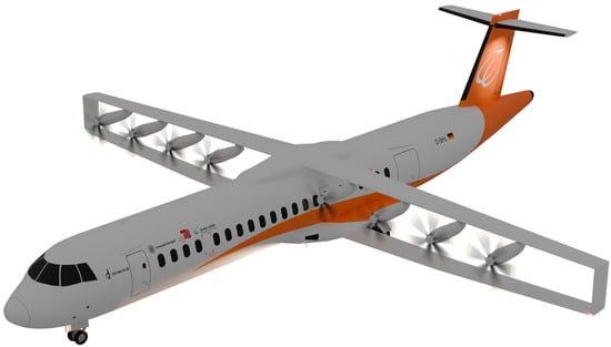
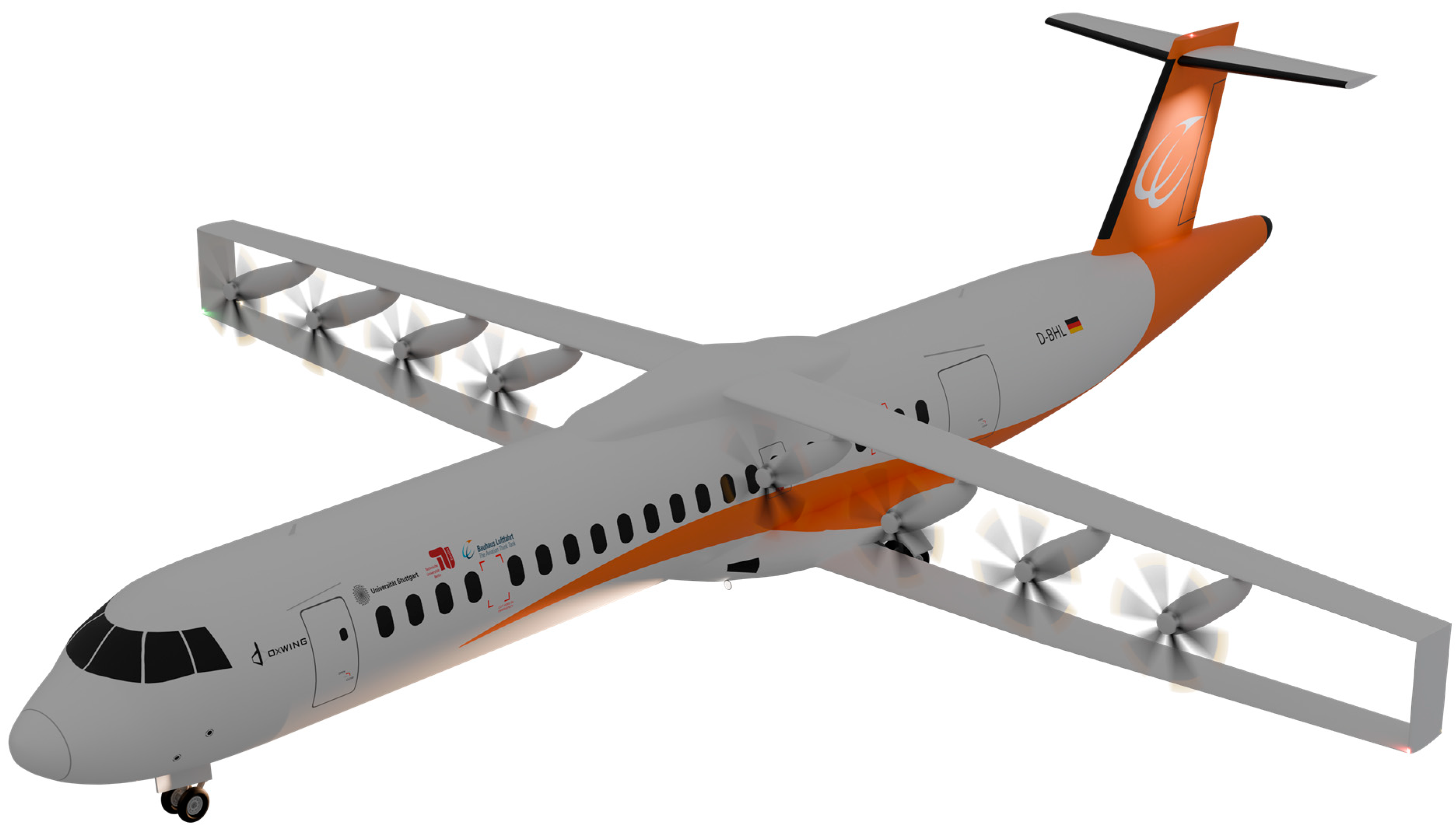
The foundation of the aircraft-design tasks in the DOXWING project is set by a representative, virtual model of the ATR72-500 regional aircraft [8]. Following a calibration of the aircraft design software SUAVE [9] by the Institute of Aircraft Design of the University of Stuttgart (IFB) on publicly available aircraft data, this reference was then further modified to form the basis for all planned studies; as the entry into service (EIS) of this modified version is assumed to be in the year 2045, technological advancements had to be integrated. This included, but was not limited to, alternative material choices and changed subsystems with the respective impact on mass. Yet, no generalized technological improvements were applied, leading to a rather conservative approach apart from the change towards a box-wing configuration. After the implementation of these technological advancements, the aircraft was altered to become the study aircraft, incorporating a box-wing powered by eight electrically driven propellers as a consequence of the electrification of the propulsion system; the energy system was altered to a purely hydrogen-based configuration, generating the required electric power by high-temperature polymer electrolyte fuel cells (HT-PEMFCs). Details on the propulsion system can be found in Section 3, and an overview of the most prominent top-level aircraft requirements (TLARs) is shown in Table 1 below, alongside a rendering of a concept of the study aircraft during the initial assessment phase in Figure 1. As the study aircraft is part of an ongoing investigation and the study at hand focuses on a comparative assessment, absolute aircraft masses are not fixed yet.
Table 1.
Selected top-level aircraft requirements of the study aircraft.
Figure 1.
Visualization of the study aircraft’s current design iteration for the purpose of this study.
As depicted in Figure 1 below, the current aircraft concept features a box-wing configuration with positive stagger, thus, with the upper wing being in front of the lower wing in x-direction. Nevertheless, the results of the topology assessment performed within the presented studies are valid for both positive and negative stagger, as the general trends and space constraints remain comparable. The only exception to this assumption is the reduced blocking effect of the nacelles, if placed not in between the wings in vertical dimension. As a result of the wing–propeller interaction and the structural coupling of the two wings at the wingtip, the aspect ratio of the wing can be significantly increased. This underlines the requirement of a detailed aero-structural analysis as foreseen in the DOXWING project.
The most prominent system change from reference to study aircraft was imposed by the transition from kerosene to liquid hydrogen (LH2) as energy source. Due to the space and mass requirements of aerospace applications, the storage of H2 in liquid form is viewed as the most sensible for future aircraft applications [10, 11]. Numerous studies on tank integration and aircraft design with varying outcomes have been performed (e.g., [11, 12, 13]); nevertheless, to keep the configuration changes of the study aircraft to a minimum, an aft-only tank configuration featuring two LH2 tanks in the very rear of the fuselage has been chosen. Two tanks are required for redundancy reasons, and the rear placement has multiple advantages regarding (passenger) safety, ease of integration and result comparison. The placement of the cargo holds of the reference aircraft in front and aft of the passenger cabin remains unchanged.
1.2. Boundary Conditions
As the presented study assumes various changes within the current aviation system, multiple boundary conditions have to be specified upfront. On a global scale, hydrogen-propelled aircraft require adequate H2 airport infrastructure matching the needs of the aircraft fleet. This comes with the coupled assumption that H2 aircraft and airport certifications and safety protocols are available. New methods for fault propagation and fault analysis for H2 propulsion systems—irrespective of the energy conversion method—need to be derived and put into practice, just to name core essentials.
With regard to aircraft-specific boundary conditions, the compatibility of aircraft and airport is kept constant, including dimensions, masses and safety-related practices. Apart from a change in refueling system, aircraft handling, boarding, luggage handling, etc., are assumed unchanged, as the longitudinal spacing of the upper and lower wing (i.e., stagger) is rather small.
2. Methods and Assumptions
Due to the uniqueness of the study aircraft, a set of assumptions needs to be specified upfront. These assumptions align with the introduced boundary conditions as well as the goal of the studies presented and are stated in Section 2.1. Furthermore, the impact of failure cases on the selection of architectures due to the setup of the powertrain options is outlined in Section 2.2. Finally, the selection criteria deployed to reduce the number of reasonable powertrain architectures are introduced (Section 2.3). Together with the system characteristics introduced in Section 3, a thorough configuration assessment is possible.
2.1. Overarching Assumptions
On aircraft level, multiple assumptions need to be specified upfront in order to provide a solid basis for the presented studies. Generally, aircraft systems come with the required redundancy or safety factors, respectively, and exclusively symmetrical installation options are considered. Structural parts such as the wing and its design remain constant, with the exception that the wing is allowed to be shifted in the x-position to accommodate center of gravity (CG) changes. As the design range of the aircraft remains constant, only changes in the propulsion system (mass, drag, CG shift) are able to influence the H2 quantity on board. However, this is disregarded to facilitate a fair comparison of propulsion architectures with regard to transmission distances and general system placement. This in turn eases the assumption of constant maximum takeoff (TO) power of 4 MW (see Section 1.1) irrespective of the architecture under consideration, which is especially important for the sizing of most propulsion-related components and has a direct impact on system mass. For wing-based architectures, a constant power distribution across all nacelles is assumed, even though non-uniform distributions might bear the potential to reduce wing structural mass and tackle problems with regard to aerodynamic blocking. The wing stagger is assumed to be 1.5 m in the x-direction at the root, so the aerodynamic interactions can be fully exploited. This reduces the typical box-wing characteristics to a rather conventional behavior, especially regarding CG location, stall characteristics and trim drag. Further studies will be performed both on aerodynamic and structural interaction.
Moreover, no synergies concerning the propulsion system are considered. This is especially important with regard to waste-heat utilization of the FCs, as the cryogenic temperatures of the LH2 bear the potential to alleviate the load on the thermal management system (TMS). Additionally, the waste heat could help pressurize the tanks and precondition both the reactant and the oxidizer for further utilization within the HT-PEMFCs or be coupled with the environmental control system (ECS) of the aircraft. A coupled cooling system serving the electric components as well as the FCs simultaneously is disregarded, since these effects are not yet quantified by the project. Likewise, the processing of H2 due to boil-off at the tanks is disregarded for simplicity reasons. Lastly, the incorporation of superconducting electric components or the cooling of electric components by cryogenic hydrogen is disregarded.
2.2. Failure Considerations
As the study at hand stays in the propulsion system control volume between LH2 tanks and propellers, the evaluated failure cases remain focused on the respective components. Thus, neither the propeller nor the tank is considered. Generally, the architecture design closely follows currently implemented strategies for kerosene aircraft. For example, fuel lines and cables are not redundant, if not specifically mentioned otherwise. The same accounts for mechanical failures such as those of the gearbox or bearings.
Nevertheless, the classical one engine inoperative (OEI) approach of aircraft using turboprop or turbofan engines is altered, as the propulsion system has fundamentally changed characteristics; due to the separation of energy conversion and thrust generation, the terms OPI (one propulsor inoperative) and OSI (one stack inoperative) are employed. They indirectly distinguish between aircraft-level and nacelle-level power reduction or loss.
Generally, an OPI condition may occur only if the electric machine or the power electronics within a nacelle fail, irrespective of location and status of the FCs. This reduces the power-to-thrust conversion capabilities to 7/8th but has no impact on the available electrical power on aircraft level. However, secondary consequences, such as a reduced blown-wing effect with its reduced high-lift performance or lateral maneuverability, will be affected. OSI effects need to be differentiated according to the architecture considered. The term itself implies that a full FC failure is not considered, as an FC always consists of multiple stacks (for this study). This furthermore implies that a stack failure can always be contained, increasing slightly the mass of the FC system.
For fuselage-bound FCs, a stack failure would lead to a general power reduction for all or selected propellers (depending on the implemented strategy on overall aircraft design, OAD), but no propeller shut-down, as all propellers are connected to the main power bus fed by all FCs. Electric cross-feeds ensure redundant electric power distribution. Furthermore, as both tanks may feed all FCs, H2 supply issues only lead to a range reduction. Stack failures in nacelle-based FCs can either lead to a single propeller power reduction or a reduction in aircraft power through the use of cross-feeds and rebalancing. Yet, under the simple assumption of two stacks per nacelle, a single stack failure would lead to a power reduction of only 6.25% (not including cross-feed losses).
TMS failures must be seen as more severe than stack failures, as an FC placed within the nacelle will be served by a single system due to mass and space constraints. Thus, depending on the failed component of the TMS and FC characteristics, a power degradation or total shutdown of the FC must be expected. For fuselage-bound power systems, the redundant TMS (see Section 3.4 below) ensures a preservation of at least half of the available FC power, depending on the oversizing factor of the TMS as well as the current environmental conditions, as the load on the TMS during cruise is a fraction of the load during a hot-and-high takeoff.
2.3. Selection Process
For an efficient limitation of the number of sensible architectures, a two-phased selection process was applied. Upfront, a preselection based on numerous general boundary conditions was performed, before a more detailed downselection process was employed on the remaining architectures. The preselection was mainly based on constraints regarding geometric integration, safety and CG. More details as well as the results of this assessment can be found in Section 4.1.
To identify the most viable powertrain integration strategy from potential architectures identified during the preselection phase, a systematic downselection methodology was applied. This approach follows the principles of a Weighted Pugh Matrix (WPM), a structured decision-making tool used to evaluate multiple design alternatives against a (in this case) weighted set of criteria relative to a baseline [14, 15, 16]. The primary objective of this multi-criteria decision analysis (MCDA) is not to generate absolute performance data, but to establish a relative ranking that highlights the architectural trade-offs specific to the box-wing configuration of the DOXWING concept. The results of the second phase of the selection process are outlined in Section 4.3. The benefits of this approach are the objectification of the analysis as well as the ability to obtain a structured comparison between the preselected architectures based on relevant criteria specific to the problem at hand.
The evaluation process weighs each candidate architecture relative to a reference case. For this study, the latter is defined by the installation of the FCs and TMS system within the rear fuselage, positioned in between the rear pressure bulkhead and the LH2 tanks. This baseline was selected for its architectural simplicity and high degree of safety through segregation, as it completely isolates the H2 infrastructure from the passenger cabin. Furthermore, the proximity of the FCs to the tanks minimizes the length of cryogenic lines and associated pump power requirements. However, this reference entails long high-voltage (HV) transmission lines to the wing-mounted propulsors and intensifies the aft-CG challenge inherent to the structural modifications of the fuselage.
Each alternative architecture is scored against this baseline on non-uniform weighted selection criteria ranging from significantly inferior to significantly superior in four categories with four criteria each. These raw scores are then processed through a hierarchical weighting system comprising four main categories detailed in the paragraphs below. Additionally, the weights of the categories and criteria are detailed in Table A1 in the Appendix A. Finally, the weighted totals are calculated through the multiplication of the score of each criterion by its weight followed by a summation per alternative, clearly revealing the top-performing architecture.
1. Safety & Certification
The category Safety & Certification establishes the foundational layer of the assessment, assigned a weighting of 25%. While safety is paramount in aviation, this weighting reflects that all considered architectures must inherently meet minimum safety standards to be viable; the differentiation lies in the effort required to achieve safe operation. The evaluation prioritizes architectures that physically separate high-pressure or cryogenic systems from the passenger cabin. Closely linked is the safety of the transmission lines, which assesses the risk exposure of LH2 pipes and HV cables passing through critical zones. Further criteria include crashworthiness considerations, evaluating whether heavy components—specifically the FC system—are secured against penetrating the cabin or fuel tanks in emergency landing scenarios etc., as well as the ease of venting and fire suppression. The latter favors integration concepts that allow for H2 to escape directly overboard without accumulating in enclosed fairings or fuselage sections. In particular, the ventilation around H2 pipes close to the cabin can be challenging due to space constraints.
2. Aircraft Performance
Given the overarching goal of the DOXWING project to demonstrate the efficiency gains of the box-wing configuration, aircraft performance considerations are assigned the highest weighting of 35%. This category aggregates the direct impact of the architectures on the aircraft’s energy budget and aerodynamics. A critical factor here is the aerodynamic impact, distinguishing between internal solutions that maintain the outer mold line and external solutions, such as enlarged nacelles, that introduce interference drag or aerodynamic blocking. Equal importance is placed on system mass and accompanying snowball effects, accounting for both the primary mass of the powertrain components and the secondary structural reinforcements required. Thermal efficiency and synergies are also placed within this category; architectures that could facilitate the use of waste heat for reactant conditioning or those that position heat exchangers (HEXs) in regions of beneficial airflow without excessive drag penalties receive higher ratings, as these factors directly influence the dimensioning of the FC stacks. Nevertheless, as stated in Section 2.1 above, no synergies are accounted for within the architecture performance. Finally, transmission losses are considered, penalizing architectures that require extensive pipe or cable lengths.
3. Configuration & Integration
The category Configuration & Integration is weighted at 30%, reflecting the severe constraints imposed by the aircraft configuration of the study and the specific aerodynamics of the box-wing. The dominant criterion within this cluster is the CG influence. Since the elongation of the rear fuselage for LH2-tank integration creates a naturally tail-heavy aircraft, architectures that utilize the propulsion system mass to counterbalance this effect are rated higher. The category also evaluates geometric packaging, assessing whether components fit within existing voids or require fuselage or nacelle elongation. Furthermore, the criterion of structural integration considers the introduction of loads into the airframe. Consideration is also given to the impact on landing gear and ground clearance, particularly for under-wing or belly-mounted options.
4. Operations & Complexity
Finally, Operations & Complexity is assigned a lower weighting of 10%. While operational aspects are critical for the commercial success of a mature product, they are considered secondary in this conceptual design phase, where the primary focus is on proving physical and aerodynamic feasibility. This category evaluates accessibility and maintainability, favoring positions accessible from the ground. It also considers assembly and routing complexity, penalizing architectures that require complex threading of systems through the wing box or pressure vessel.
Following the calculation of the normalized global scores, the results undergo a maturity assessment. This qualitative crosscheck examines whether an architecture is compatible with the specific characteristics of the DOXWING concept, such as the wing–propeller interaction, and if an implementation is actually feasible. The compatibility and feasibility ratings, each ranging from 1 to 5 with 5 denoting high compatibility/feasibility, are then multiplied to generate the maturity rating.
To validate the steadiness of the downselection results, a final robustness check is performed. This sensitivity analysis ensures that the ranking remains consistent even under significant variations in weighting priorities. For this evaluation, four distinct test scenarios are defined, corresponding to the four main assessment categories. In each scenario, one specific category is emphasized with a dominant weight of 50%, while the remaining 50% of the total weight is distributed equally among the other three categories (thus approximately 16.7% each). Subsequently, the arithmetic mean of the scores from these four biased scenarios is calculated. This average is then compared to the results for the standard scenario to contextualize the findings and verify whether the preferred architecture maintains its ranking regardless of the specific prioritization strategy. This structured approach ensures that the selected architecture represents not only a theoretically efficient solution but also a practically feasible integration strategy for the box-wing regional aircraft.
3. Powertrain System Characteristics
To understand the implications of the propulsion system for the architecture options, an overview of the most relevant characteristics is provided. Certainly, the final system choice is performed according to the architecture’s requirements. The following Sections 3.1 to 3.4 provide insights into the systems between LH2 tanks and propellers, while focusing on the most relevant aspects.
3.1. Hydrogen System
As the LH2 tanks are part of the overall aircraft design work, they were not analyzed or designed within the presented work. Nevertheless, to be able to provide a complete picture, the most prominent assumptions and boundary conditions are outlined below.
Two LH2 tanks are placed in the very rear of the fuselage due to redundancy reasons. They have roughly the same volume to be able to feed half of the propulsors per tank in normal operation. Yet, each tank is capable of feeding all available FCs alone during abnormal operation, requiring the tank crossfeed to operate to use all remaining fuel on board. The rear limit for the aft tank is given by the internal vertical tailplane (VTP) structure, if applicable—studies on the possibility of omitting or reducing the VTP due to the utilization of the vertical part connecting upper and lower wing as rudders will be performed as part of the project. The forward limit of the tanks is either given by the rear pressure bulkhead or—for specific architectures—the FC system between tank and pressure bulkhead.
From a technical point of view, the tanks represent the starting point for the design of the LH2 feed system to the FCs, storing the LH2 at 20 K and 1.5 bar. It is assumed that an active cooling system or vacuum pump is not required due to the rather short flight times and the potential use of foam insulation for this type of aircraft.
Similarly to the electric system (see Section 3.4), the hydrogen system consists of constant and variable components, according to the selected architecture. This is primarily based on the fixed tank location. The H2 system can be subdivided into main or propulsion-related components and secondary or safety-related components. The latter mainly consists of the tank compartment ventilation to prevent the accumulation of H2 over time due to leakages or diffusion, as well as standard and emergency tank venting to protect the tank against rupture due to undesired overpressure. The standard tank venting is performed via pipes in the VTP to achieve a maximum distance from ignition sources on the ground, and in case of its dysfunction, an emergency venting system can prevent tank rupture via burst disks and short pipes directly to the fuselage skin. The mass of the refueling connector and system is expected to be in the range of the kerosene system mass and is, therefore, neglected.
As it is expected that cryogenic systems need to be maintained or exchanged more frequently than conventional kerosene systems, no systems such as pumps are placed within the tanks. This assumption requires the integration of cold boxes (CBs); for the given aircraft concept, the main CB is expected to serve both tanks and hold accessory systems as the crossfeed connecting both tanks, booster pumps for the LH2 feed system, valves, and sensors. Therefore, this CB is placed in between both tanks. A second CB including respective systems serves the front tank only for redundancy purposes. The tank pressurization system is required to counteract the loss in tank pressure due to fuel consumption, otherwise leading to increased boil-off, pump cavitation and adverse fuel feed into the pumps. It features an electric tube-in-block vaporizer, increasing the volume of H2 just slightly at around 28 K and 1.5 bar, as H2 in this state experiences the strongest volume increase when based at 20 K. However, the heater is expected to consume around 1.4 kW during takeoff based on H2 mass flow, requiring it to be placed outside the CB to prevent it from heating up.
Especially relevant for the architecture assessment and one of the few variable components within the hydrogen system is the LH2-pipe mass. This mass is derived using existing LH2-pipe technology from [17] adjusted according to aircraft requirements, thus adding a mass of 0.27 kg/m (averaged) for bellows, swirl elements, brackets, mountings and connectors as well as adjusting the required pump power according to the specified pressure loss. The rear and front LH2 feed systems transport the H2 to the front end of the forward tank, marking the beginning of the main LH2 feed system. All LH2-system masses are summarized in Table 2 below.
Table 2.
LH2 system masses.
Generally, there will be one main LH2 pipe for each FC system feeding half of the required propulsive power. Therefore, only one pipe feeds all FCs for wing-based architectures per wing with an interconnecting crossflow system to the other wing.
The conditioning of the H2 for further utilization within the FC system is assumed to be part of the latter and, thus, not further considered here. Apart from a mass contribution close to that of the tank pressurization system, the main influence is expected to be coming from the required power to heat the hydrogen from 20 K to around 430 K required for the efficient and safe operation of the HT-PEMFCs. Furthermore, it is assumed that the conditioning will always take place in the vicinity of the consumer, eliminating the need for gaseous hydrogen systems outside of the FC system.
It has to be noted that all systems are designed under the assumption of 4 MW total takeoff power. Thus, system masses are derived from the maximum fuel flow of the FC. This assumption is not altered if the architecture requires that the aircraft consumes more/less energy.
3.2. Fuel Cell System
Previous studies of the DOXWING project found HT-PEMFCs to be the most suitable FC type for the intended application, given the foreseeable technological progress for an EIS in 2045. As the FC system will be operated in vastly changing environmental conditions due to the flight profile and geographical deployment, the balance of plant (BoP) requires special consideration. Only with proper conditioned reactants will the system achieve minimal degradation while running at optimal efficiency and power output. The latter will be between 100 kW and 500 kW per stack, depending on the chosen architecture. This ensures modularity, exchangeability, and maintainability as well as proper system integration and cooling. As stated in Section 2.2, a single FC always contains multiple stacks for fault-mitigation purposes.
As the total assumed aircraft power for this study is set to 4 MW, this number is used to size related systems. During takeoff, a total H2 mass flow of approximately 90 g/s was calculated for all stacks. To be able to account for non-used hydrogen and accumulating system inefficiencies, this value was increased to a conservative 100 g/s. This value is especially important for the sizing of the hydrogen pipes, pumps and other distribution and storage systems. All remaining performance metrics of the FC system are stated in Table 3. Note that these values are only used for the assessment of the architecture options and other initial estimations but will be calculated based on the actual power requirements and, thus, overall system performance for the aircraft design.
Table 3.
Fuel cell system parameters.
The H2 inlet temperature is chosen to be on the lower bound for two reasons: on the one hand, to reduce the energy required for the temperature increase from 20 K to 453 K (especially, as synergies are not foreseen during the first assessment), and on the other hand, to utilize the H2 flow to aid with stack cooling.
3.3. Thermal Management System
Even though various studies have been performed regarding the assessment of unconventional TMS architecture options within the DOXWING project, a conventional TMS including two or more heat exchangers (HEXs) was used for the propulsion architecture to de-risk the assessment. A minimum of two systems is kept for redundancy reasons and ease of integration. The main components are a cooling fluid reservoir, pumps, coolant pipes, HEXs and fans for sufficient airflow during low-speed phases requiring high power such as takeoff. A diffusor and a nozzle per HEX ensure proper airflow, minimizing drag. The theoretical background as well as an overview of the underlying architecture can be found in [18].
Irrespective of the discrete architecture under consideration, the TMS is bound to scaling laws. The most prominent components are the coolant pipes with their respective pump powers, enabling the required circulation of the coolant between stack and HEX. For all assessed architectures, the required coolant mass flow during takeoff was between 4.7 kg/s and 19 kg/s, underlining the massive impact of pipe diameter and, thus, length according to the regarded architecture. Therefore, the architecture assessment places a focus on HEX integrational position on aircraft level, as the sizing of TMS components according to the respective waste heat load is less demanding than the distance between heat source and heat sink. The extreme cases reflecting an FC in each nacelle with uniform power distribution across the wing (500 kW propulsive power per nacelle) and concentrated power generation with two FC systems of 2 MW propulsive power each are summarized in Table 4 below. Note that the block fuel (BF) impact was calculated using trade factors from the reference aircraft provided by the IFB. These factors indicate a ∆BF of 1.17% for a change of ±200 kg as well as a ∆BF of 2.36% for a delta of ±1 kN drag around the design point (assumption of linearity for the considered divergence from the design point). Furthermore, the heat load was calculated using the FC system efficiency according to the prescribed propulsive power.
Table 4.
Comparison of major TMS parameters for centralized and decentralized architectures.
3.4. Electric Propulsion System
The electric propulsion system consists of the components that transform the incoming electric power into propulsive power. This includes power electronics (inverter, converter, secondary systems), electric motor, reduction gearbox and propeller. As the associated components remain constant throughout the architecture assessment due to the assumption of constant maximum power requirement (see Section 2.1) as well as even power distribution across all propellers, only a brief description is given. Apart from the power transmission buses, the electric propulsion system acts as a constant mass distributed among the nacelles, reducing the wing-root bending moment. Note that the question of even or non-uniform power distribution along the wingspan, together with the cooling requirements of the electric components, is not addressed in this paper.
The electric power transmission buses are assumed to be HV direct current (DC) lines to minimize transmission losses, requiring a DC/DC step-up converter following the FCs on the generating side and a converter–inverter unit at the receiving side. However, for very short transmission distances (i.e., a placement of the FCs within the nacelles), the components might be reduced to feature only a single inverter–converter module, as conversion losses and transmission losses are weighted against each other. Additionally, omitting components reduces the mass and volume of the system. The power transmission bus mass per unit length was kept constant for all investigated architectures at a value of 5.0 kg/m, as can be seen in Table 5 below. The number of DC buses installed depends on the architecture setup and influences the mass of the architecture.
Table 5.
Electric propulsion system parameters.
A battery is required for FC startup and emergency operations. As this mass is constant throughout all architectures it is not further detailed here. Nevertheless, the electric transmission from battery to the primary FC, which subsequently will power the startup of the other FCs or stacks, respectively, varies according to the architecture. Therefore, the battery is assumed to be placed within the CG of the aircraft.
4. Results
The following section summarizes the results of the two-phased downselection approach. An overview with respect to the preselection of architectures is given in Section 4.1, leaving nine generally viable options for the second phase. The latter is then showcased in Section 4.3 along with a discussion of the most prominent advantages and disadvantages of the respective architectures as well as more detailed insight into the most promising architecture.
4.1. Preselection of Architectures
The downselection of the architectures was performed in a two-phased approach. Initially, FC installation options that were infeasible due to, e.g., geometric boundary conditions, safety reasons or undesired CG problems, were uncovered and disregarded. The remaining options were clustered according to their location on aircraft level and taken into consideration for the final analysis.
Nevertheless, preceding this two-phased approach, the question of architectural influence on mass and power consumption needs to be investigated to be able to perform data-based decisions. Generally, all architectures can be separated into centralized and decentralized candidates; for example, a nacelle-based architecture has eight power generators, one in each nacelle, and is therefore decentralized, while fuselage-based options have two FC systems in close proximity and are, thus, centralized.
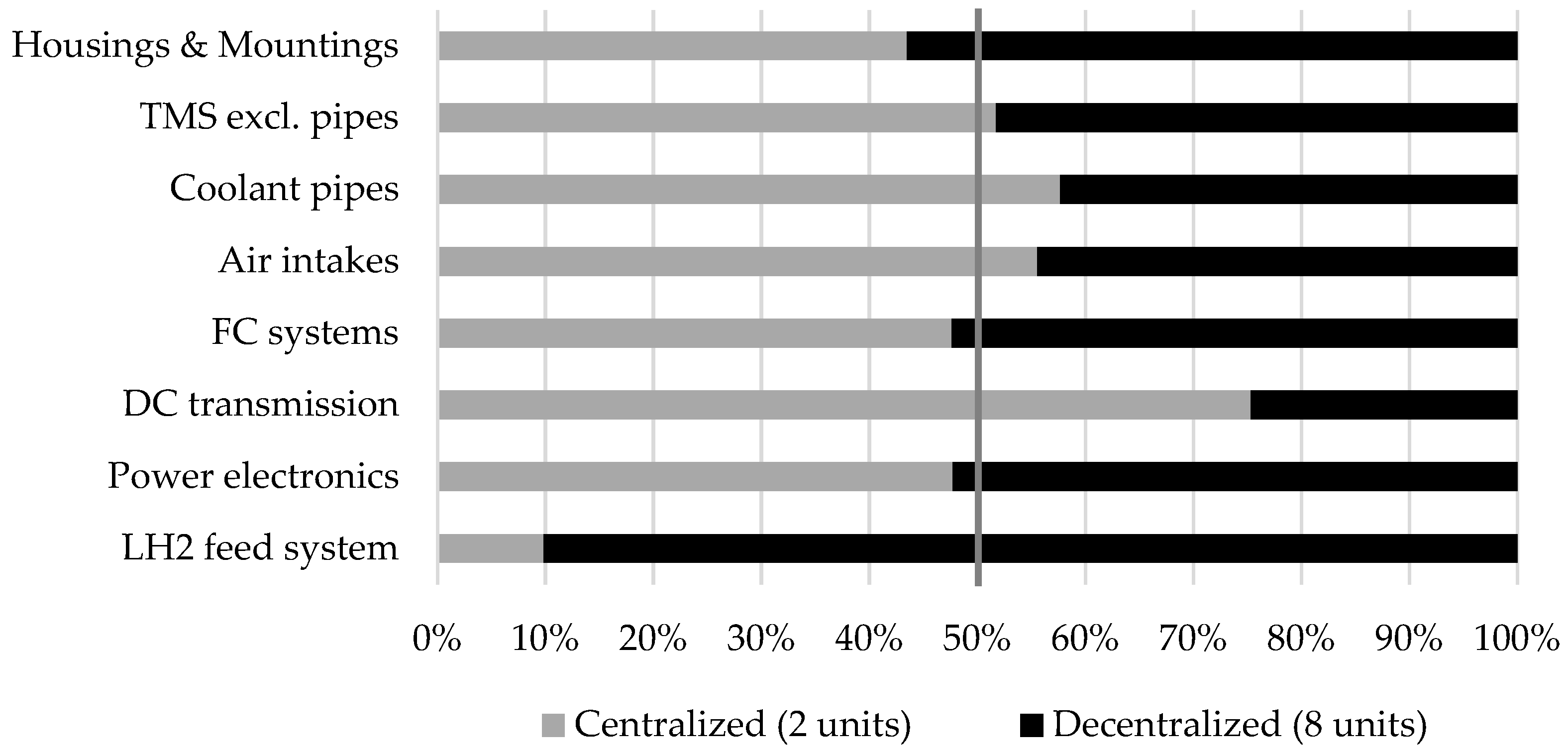
Even though decentralized systems have strongly reduced electric transmission losses due to their vicinity to the consumers, multiplications of systems such as cooling fans, coolant and H2 pumps, vaporizers or compressors diminish this advantage with regard to total FC power load. This behavior is even worse with regard to masses; while limiting the maximum point load allows for lighter local structural reinforcements, distributed architectures suffer significantly from the square-cube law applied to the housing masses and the multiplication of interface hardware (vibration isolators, brackets, connectors, etc.). Consequently, the power-specific mass for housing and mounting is estimated to be higher for distributed solutions compared to centralized systems, as illustrated in Figure 2 below. Note that Figure 2 only shows focal, architecture-dependent mass changes, thus neglecting masses constant for all architectures. The higher integration mass of distributed options is balanced by the reduction in overall transmission masses, as the LH2 feed systems are roughly half of the mass of the HVDC transmission lines per unit length. Thus, even though strong local changes might occur, masses are equalized on the overall aircraft level. With a delta of around 76 kg or 2.9% for architecture-dependent masses, the assumption of equal mass for distributed and non-distributed architectures is seen as valid. However, variation in CG position and its influence on aircraft performance is still rated accordingly, especially as only 22.5% of the total propulsion mass remains constant in location irrespective of the architecture.
Figure 2.
Relative comparison of architecture-dependent mass items.
4.1.1. Infeasible Fuel Cell Placements
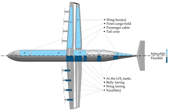
Due to the changed wing design of the study aircraft towards a significantly slimmer box-wing, the volume inside the wing boxes of upper and lower wing is greatly reduced. Nevertheless, as the utilization of LH2 as the energy source for the aircraft eliminates the need to store liquid fuel within wing-integral tanks, this space is available to accommodate other systems. With an initial estimate of the wing-box dimensions of height h = 0.17 m and length l = 0.90 m (wing root) and h = 0.08 m and l = 0.41 m (wing tip) of upper and lower wing, the integration of FCs including the required systems (ducts, exhausts, TMS interface, etc.) is deemed infeasible, especially considering the required thermal shielding of the composite structure foreseen for the structural parts of the wing. Results of the project-specific ongoing aero-structural wing assessment indicate that the upper and lower wing will have very similar wing-box dimensions. Yet, the integration of propulsive components is only reasonable for the upper wing, as it carries the propulsors and would, thus, enable short transmission distances from wing-based FCs to the nacelles.
Another area that is excluded from the detailed assessment is the option to place the FC system in the tail cone of the fuselage below the empennage. This area is expected to be volumetrically infeasible for the integration of the FCs and their required systems and also filled by empennage actuation systems, even though the vertical parts of the box-wing might replace some of the VTP area.
Following the geometric feasibility assessment, options with direct operational safety concerns were addressed. This is especially important with regard to passenger (PAX) safety and the coupled limited placement options for FCs in or in the vicinity of the passenger cabin, as seen, e.g., in [19]. Moreover, as the study aircraft is a direct derivative of the ATR72, the space below the cabin is deemed infeasible to carry FCs with the required total power as well as the coupled systems and hazard prevention installations (protection against H2 ingress, heat, flames, etc.). Less relevant for the technical study at hand, but still important to consider is the noise impact of the propulsive systems on the cabin and therefore comfort of the PAX.
Finally, a placement of the FC in the area of the forward cargo hold of the ATR72 reference aircraft, thus between cockpit and cabin, comes with a multitude of challenges; the position implies long and heavy transmission lengths for H2 and electric power being routed in close proximity of the cabin, infringing high safety standards. More importantly, the placement of the heaviest propulsion-related components apart from the LH2 tanks in the very front of the fuselage comes with CGX challenges that are hard to circumnavigate even for a clean-sheet aircraft design, as other boundary conditions need to be matched as well. An overview of all feasible and infeasible options is depicted in Figure 3.
Figure 3.
Sketch of feasible and infeasible fuel cell placement options for the box-wing regional aircraft.
4.1.2. Generally Feasible Fuel Cell Placements
Even though the advantages and drawbacks of the feasible options are discussed in the sections below, an overview of these is given here to highlight the general reasons for their viability. Additionally, the lower half of Figure 3 in the section above outlines these options in a simplified sketch.
The placement of the FCs within the nacelles behind the propellers would be in line with the classical installation of the power generating systems in proximity to the thrust generation. The nacelles are rather free in their dimensions due to the spacing between the wings, facilitating the integration of closely interconnected systems. However, this comes with the prerequisite to respect issues concerning propeller blocking and aerodynamic interference but also considering the strongly coupled box-wing aerodynamics.
Due to the changed location of the energy carrier from the wing—and thus close to the consumer—towards the rear fuselage section, a position shift of the consumer is therefore also viable. The fuselage length may be adjusted rather freely according to the needs of the FC integration, with placement options in front of, in between or aft of the two LH2 tanks, depending on other aircraft requirements. Nevertheless, takeoff rotation angles and thus landing gear lengths must be kept within a reasonable limit as the fuselage length grows.
The third main category of viable positioning options is enabled by the integration of the box-wing and the landing gear into the aircraft; based on the size of the required aerodynamic fairings, a fairing-based approach might utilize available volume in combination with a rather simple HEX integration of the TMS.
Finally, a combination of FC placement options is viable, but drawbacks based on doubling of secondary systems and an increased routing effort for hydrogen and power transmission need to be respected and assessed carefully.
4.2. Candidate Architectures Overview
Following the preliminary screening of the initial design space, nine distinct powertrain integration architectures (labeled A through I) were identified for detailed assessment. To facilitate a structured comparison, these candidates are classified into four primary groups based on their physical integration domain: nacelle-based, fairing-based, fuselage-based, and hybrid configurations.
The nacelle-based group (architecture A) represents a distributed approach, placing the FCs directly at the consumer within the nacelles. The fairing-based group (architectures B and C) utilizes non-pressurized aerodynamic structures—specifically the wing-to-body fairing and the belly fairing—to house the systems outside the primary fuselage structure. The fuselage-based group (architectures D, E, and F) focuses on integrating the systems within the extended fuselage section dedicated to the hydrogen storage, varying the position relative to the LH2 tanks. Finally, the hybrid group (architectures G, H, and I) explores the potential of splitting the system mass between multiple domains to improve CG and volume utilization. Table 6 provides a systematic overview of the candidate architectures, their assigned identifiers, and their specific integration locations.
Table 6.
Designation, grouping and specific location of candidate architectures.
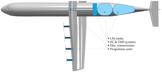
Architecture D is selected as the reference case (baseline) for the subsequent downselection presented in Section 4.3. This configuration, with FCs positioned directly upstream of the forward LH2 tank, represents a conservative, safety-oriented and straight-forward approach that prioritizes the segregation of H2 systems from the passenger cabin via the pressure bulkhead (and rear cargo hold) while minimizing cryogenic line lengths. A simplified sketch of architecture D is depicted in Figure 4. Note that components are not to scale and subcomponents such as cold boxes, etc., are not shown, as it is solely intended to underline the general layout of this option. The propulsion units consist of power electronics, an electric motor and a gearbox.
Figure 4.
Schematic top view of reference architecture D showing a simplified internal component layout; starboard wing omitted for clarity.
4.3. Downselection of Candidate Architectures
The findings from the structured evaluation of the remaining architectural candidates, conducted via the tailored weighted Pugh matrix, are presented in a two-stage process. First, the results are broken down by the individual assessment categories to reveal configuration-specific trade-offs (Section 4.3.1). Subsequently in Section 4.3.2, a comprehensive general analysis is performed to provide a holistic view of the architectural rankings.
4.3.1. Category-Internal Assessment
1. Safety & Certification
The assessment of the first category, Safety & Certification, shows a clear preference for the fuselage-based placement options of the propulsion systems, with the reference architecture (option D) achieving the best overall normalized score of 0.5. Generally, all architectures with FC placements in the fairings have issues with passenger proximity, especially concerning crash impact behavior. All non-fuselage-bound architectures additionally have the H2 transmission lines in close PAX proximity, leading to a worse rating than options solely behind the pressure bulkhead. Note that the routing of H2 pipes outside of the fuselage was not considered in this study, as this comes with a set of additional challenges, e.g., danger of damage by ground vehicles. However, this is still valid for H2 pipes within the wings, reducing option A’s rating within this criterion. Furthermore, venting through the VTP is favored, as this achieves the greatest distance from potential ignition sources. The only architecture that increases the zonal safety due to a proper physical separation is the nacelle placement of the FC, as this option avoids any FC within ore close to the fuselage. However, even though HV electric wiring with passenger proximity is a well-established technology, risks like arcing or short circuits need to be accounted for. Nevertheless, it is deemed safer than H2 transmission due to its systemic risks such as leakage, flammability, and embrittlement. Concerning the fuselage-bound architectures, the placement in the rear is less favorable, as it is prone to damage during a tail strike. Thus, the multi-criteria safety analysis leads to a clear disadvantage of all configurations that feature fairing-based systems (B, C and G) due to the proximity to the cabin. These configurations share the lowest normalized score of 0.17.
2. Aircraft Performance
Looking at the ratings purely within the aircraft performance category, the scoring becomes more complex. Even though the values for the normalized score have a low spread and lie in the range of 0.37 to 0.52, the reasons for the scoring are fundamentally different. The nacelle-bound option is superior when it comes to mass distribution, snowball effects and electric transmission losses; with the FCs at close range to the electric machine, losses are kept to the minimum. Additionally, the shift of propulsive mass towards the wings has a load-alleviating impact, reducing overall structural disadvantages. On the downside, this configuration has a high aerodynamic interdependency, as enlarged nacelles lead to blocking effects and a less favorable wing–propeller interaction, with the latter being rather important for the box-wing configuration at hand. Valid for option A, but also for all configurations with distributed systems, is the reduced potential to make use of synergies in terms of waste heat utilization or cryogenic cooling. The fairing-based architectures gain the highest scoring within the aircraft performance category, mainly due to the favorable position on aircraft level. Nevertheless, the enlargement of the fairing and thus the cross-sectional aera of the outer mold line is expected to have a more negative effect than the elongation of the fuselage, as all concepts feature an elongation of the fuselage due to the integration of the LH2 tanks, and the delta due to the FC system integration is rather low. Note that long H2 transmission pipes mainly increase the pump power requirements slightly, whereas electric transmissions have an impact on overall system efficiency, with direct dependency on transmission length. The lowest aircraft performance rating, with a normalized score of 0.37, was attributed to architecture G, as the drawbacks from the aerodynamics and the low synergistic potential cannot be outweighed by low transmission losses and minor snowball effects.
3. Configuration & Integration
Due to the large propulsive system mass introduced, the impact of this mass on CG is the criterion with the highest global weight. Improper integration leads to unfavorable wing positions, resulting not only in adverse trim drag, but also in additional structural disadvantages as well as heavy landing gear modifications. The farther to the front the propulsive system mass is placed, the better the rating for the configuration at hand, thus scoring option A highest at 0.60 (normalized). For configurations with no fuselage elongation, tail clearance is improved, reducing the required landing gear length. However, even though this is the case for architecture C, its additional belly fairing volume and non-existent load paths reduce this advantage. Even more, proper shielding for crash cases (e.g., gear-up landing) is required to protect the cabin from the FC system leaking or penetrating the cabin space. The only option with a clear structural advantage for the integration of the FC systems is the wing-based architecture, as the load-bearing pylons are in place irrespective of the configuration (dimensioning seen as secondary). In terms of packaging, the utilization of space around the end caps of the tanks is seen as optimal, as this space would otherwise stay unused.
4. Operations & Complexity
Even though it is of secondary importance for this conceptual design study, the handling of the architectures contributes 10% of the global weight. It is clearly visible that hybrid candidates fall behind, as multiple installation locations increase the effort for initial installation, maintenance and routings. This is reflected by very low normalized scores of 0.03 to 0.10. The rear fuselage option (F) has the advantage of easy access, similarly to current auxiliary power units (APUs), and facilitates installation, achieving the highest score in this category with 0.52. On first sight, the nacelle-bound architecture seems attractive in terms of accessibility, but the second wing below the nacelles strongly reduces simple access, requiring specialized equipment. The same accounts for the wing-fairing installation option. Nevertheless, installation complexity is low apart from the LH2 transmission lines for both concepts.
4.3.2. Holistic Assessment
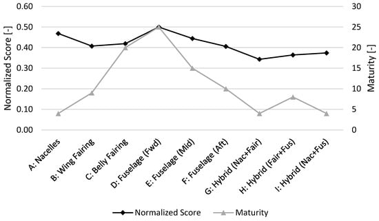
Synthesizing the results from the category-internal assessments reveals that the reference architecture D (fuselage-based, forward of tank) achieves the highest overall normalized rating in the standard scenario with a score of 0.50. It is important to note that this specific score is an intrinsic mathematical consequence of the WPM methodology, where the baseline serves as the neutral zero-point for all relative comparisons. However, the circumstance that no other architecture managed to exceed this baseline score indicates that the reference represents a local optimum within the defined design space and applied evaluation criteria. This is primarily driven by its dominance in the safety category, where it clearly outperforms all other architectures by effectively segregating the H2 system from the passenger cabin while allowing for optimal venting and crashworthiness. The normalized score of all considered architectures is shown in Figure 5 (black line). Although the fuselage-based group as a whole suffers from the highest electrical transmission losses due to the long distance between the rear-located power generation and the wing-mounted propulsors, architecture D mitigates this disadvantage best within its group by placing the fuel cells as far forward as possible, thus shortening the HV cables compared to options E and F. In contrast, architecture A (nacelle-based) follows as a close competitor with a normalized score of 0.47, benefiting heavily from its decent CG location and minimal electrical transmission losses, though it is penalized for its complex H2 routing and limited thermal synergies. The fairing-based solutions (architectures B and C) fall behind, primarily due to the severe safety penalty regarding zonal safety and the risks associated with pressurized H2 components located in the unpressurized wing-to-body or belly fairings adjacent to the cabin. Finally, the hybrid architectures (G, H, I) consistently rank lowest (norm. scores between 0.34 and 0.37). Despite their theoretical potential to optimize volume usage, the aggregation of penalties—combining the aerodynamic drag of external components with the routing complexities of internal storage—results in a system that accumulates the downsides of multiple integration strategies rather than offering a synergistic compromise.
Figure 5.
Normalized score and maturity score of candidate architectures.
Following the main rating of the architectures, a maturity assessment was performed, see Figure 5 (gray line). The central purpose of this assessment is to crosscheck if the architectures are compatible with the specific boundary conditions of the DOXWING aircraft (thus not only box-wing aircraft in general) as well as whether their implementation into the aircraft is feasible. Due to the multiplication of both maturity criteria, the high implementation feasibility of the nacelle-based architecture is shattered by the low compatibility with the DOXWING concept, especially due to the aerodynamic blocking of the enlarged nacelles. This diminishes the core aerodynamic advantage of the DOXWING configuration. Interesting is the comparison of both fairing-based architectures, as their normalized score is very similar, but the maturity rating reveals a strong discrepancy. This is mainly based on the different locations and sizes of the fairings; the wing fairing is reduced in size if compared to the ATR 72 reference aircraft due to the reduced chord length and shared structural stresses of the upper and lower wing. In contrast, the belly fairing is expanded, as the (additional) lower wing and the landing gear share one common fairing. This aids the integration of the propulsion system components as well as the aerodynamic aera rule. In line with the normalized score of the WPM, the forward placement of the propulsion system within the fuselage achieves the highest score. Generally, it has the best balance between safety and CG location, a low aerodynamic impact, and builds on a proven integration strategy. Combining the normalized score of the standard scenario and the maturity assessment, the fuselage-based reference (D) and the belly fairing (C) emerge as the most viable candidates for further consideration in the study aircraft, as they offer the best compromise between systems engineering requirements and the unique aerodynamic sensitivities of the box-wing aircraft.
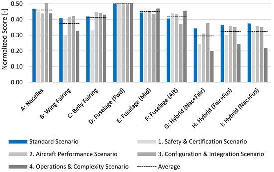
To confirm the validity of these findings against variations in weighting priorities, a robustness evaluation was performed, as visualized in Figure 6. The plot displays the normalized scores for the standard scenario (blue bars) alongside four stress-test scenarios (gray bars), where each assessment category was individually prioritized with 50% global weight. The dashed horizontal line represents the arithmetic mean of these five scenarios for each architecture, enabling a direct comparison of average and standard. By definition, the reference architecture D maintains a constant score of 0.50 across all scenarios, acting as the anchor for the comparison. The visualization highlights a distinct disadvantage of the hybrid architectures (G, H, I); the dark gray bars representing the Operations & Complexity scenario drop significantly below the average, illustrating how the architectural complexity severely penalizes these configurations. Similarly, the fairing-based group (B, C) demonstrates a lack of robustness in the Safety & Certification scenario (lightest gray bar). This specific sensitivity confirms that the proximity of large hydrogen systems to the passenger cabin and the complexity of crash-safe integration are the primary drivers, reducing their overall feasibility. Architecture A shows a relatively high degree of robustness with a narrow spread between scenarios, yet its exclusion is justified by the aforementioned aerodynamic incompatibility (see maturity assessment). At last, the robustness assessment supports the selection of the forward fuselage integration (architecture D) as the most stable and risk-averse solution, as it consistently outperforms or matches alternative architectures regardless of the specific weighting strategy applied.
Figure 6.
Standard scenario and category-specific robustness evaluation with 50% local weighing.
5. Discussion
The downselection results highlight a preference for conventional, clearly defined architectures over complex, distributed solutions. Despite the theoretical benefits of hybrid configurations, the analysis shows that established fuselage-based layouts such as architecture D offer the most robust compromise. A key driver for this outcome is the specific aerodynamic nature of the investigated box-wing configuration. While wing-based options such as architecture A offer significant advantages in wing-root bending moment alleviation, the blocking effect caused by large nacelles between the staggered wings proved detrimental. The maturity assessment was particularly valuable here, revealing that the specific stagger of only 1.5 m creates an aerodynamic sensitivity that effectively disqualifies large nacelle-based options, which might perform better on conventional tube-and-wing aircraft or box-wing aircraft with extensive stagger.
Regarding the fuselage-based candidates, the forward placement (architecture D) mitigates the risk of tail strike damage to propulsive installations and avoids the heavy structural reinforcements required for the long lever arm of rear-mounted systems (e.g., architecture F). Furthermore, the placement of FCs in tank proximity helps counteract the CG shift caused by LH2 consumption during flight. From a safety perspective, the rear luggage hold could potentially serve as an additional buffer zone between the tank/FC systems and the passenger cabin, although this is considered a secondary benefit. It is also noted that for all fuselage-integrated architectures (D–F), thermal shielding between the cryogenic tanks and the HT-PEMFCs is mandatory to prevent thermal disadvantages.
The analysis of hybrid and fairing-based options suggests that further refinement could alter the assessment. For instance, the complexity penalty for hybrid variants was severe; however, a specialized variant using a low-power FC fraction in the fuselage as an auxiliary power and propulsion unit could offer functional synergies for FC startup, ground operations and secondary consumers. Similarly, the utilization of the ATR’s underfloor space could facilitate the belly fairing option or even enable a purely underfloor architecture, depending on the actual available volume.
A critical finding of the study concerns the trade-off between transmission types; the analysis indicates that electrical transmission losses for long HV cables weigh significantly heavier than the incremental increase in pump power required for long LH2 pipes. Additionally, the mass per unit length is nearly doubled for electrical transmission. Therefore, the argument against long H2 lines is driven purely by safety and operability, not by performance or mass. Regarding the routing of these lines, placing them on the aircraft exterior, as suggested by, e.g., DLR studies [20], could enhance safety by preventing accumulation in enclosed spaces. However, this approach increases aerodynamic drag and exposes the lines to potential damage from lightning strikes or ground handling vehicles, necessitating heavy protective reinforcements.
In terms of mass estimation, the comparison revealed that centralized architectures (e.g., fuselage-based) hold only a slight mass advantage of approximately 76 kg (~2.9%) over decentralized options (e.g., nacelle-based). This difference falls within the inaccuracies of the applied modeling approach and is considered negligible. However, the installation complexity is vastly different: centralized systems require significantly less installation mass (mounts, connectors) for two large FCs compared to the hardware required for eight distributed units. It must be stated that the operating empty mass of the aircraft will inevitably increase. The added mass of the H2 system, fuselage elongation, and landing gear extension outweighs the mass saved by removing the PW127 engines. While the box-wing design allows for a smaller empennage due to the steering capability of the vertical wing parts, this mass reduction is insufficient to offset the penalties of the cryogenic tanks, which do not offer the structural efficiency of integral wing tanks.
The robustness analysis confirmed that the chosen criteria—specifically CG, aerodynamics, masses, snowball effects, and geometric packaging—were correctly prioritized. The results remained stable even under strong weighting variations, validating the selection of architecture D as final configuration. The preceding preselection is deemed crucial to facilitate the detailed downselection, as complex parameters like detailed power consumption could not be used as primary criteria due to their balanced characteristics for most architectures.
However, several limitations apply to these findings. The results are strictly valid for this specific box-wing configuration with small stagger; alterations to the geometry could massively shift the CG implications and maneuverability limits, potentially reopening the design space for wing-based options. Furthermore, detailed TMS integration was excluded to limit the assessment space, yet synergies (e.g., LH2 conditioning or reactant air heating) could have a major impact on total power consumption. Finally, economic factors such as manufacturing and recurring costs were not considered in this technical feasibility study. Future work should investigate the refinement of nacelle constellations (e.g., utilizing only inner nacelles or adjusting the power split) and perform a detailed mass comparison of fuselage sections containing tanks versus those containing the cabin to further optimize the CG limits.
6. Conclusions
Building on the reference aircraft ATR72, the box-wing study aircraft of the DOXWING project comes with a set of unique integration challenges for the HT-PEMFC powertrain. Therefore, a clear set of boundary conditions and assumptions was introduced along with relevant powertrain characteristics to be able to tailor the two-phased downselection process to the given assessment space. Following a qualitative preselection based on geometric constraints, safety considerations, aircraft stability and operability, a case-tailored weighted Pugh matrix was employed for the final downselection analysis. This method uses non-uniform weighted selection criteria within the four main categories safety, performance, integration, and complexity to generate a profound picture of the suitability of candidate architectures. Criteria with the highest global weight were CG and aerodynamic impact, mass and snowball effects, as well as geometric packaging and volume. However, pre-analyses showed that centralized and decentralized architectures have surprisingly low discrepancies in total system mass, sharpening the focus on CG, aerodynamics and safety.
The results of the multi-criteria decision analysis show a clear preference for lean architectures, as hybrid installation options fail to provide beneficial synergies and rather introduce undesired system complexities. Additionally, hybrid architectures often included fairing-based FC placements with direct impact on the safety rating due to imminent passenger proximity. The nacelle-based option achieves the second highest normalized score, as integration, CG impact and load-alleviation of the wing structure are positive. Nevertheless, the maturity assessment remarkably showed its incompatibility with the DOXWING concept, as aerodynamic blocking strongly reduces the wing–propeller interaction that is central to the double-wing concept. Even after a rigorous robustness assessment, the reference architecture integrating the propulsion system downstream of the pressure bulkhead and upstream of the forward LH2 tank achieved the highest normalized score. Even though this configuration scored highest only within the safety category, its consistently high ratings yielded an overall dominance. This was underlined by both the maturity and robustness assessments, giving confidence in the performed evaluation. Facilitating integration, maintenance and application of safety requirements together with solid aerodynamic performance and low drawbacks concerning CG position, this architecture will be applied in the future DOXWING aircraft design studies.
Author Contributions
Conceptualization, U.C.J.R. and M.H.; methodology, U.C.J.R.; software, U.C.J.R.; validation, U.C.J.R.; formal analysis, U.C.J.R.; investigation, U.C.J.R.; resources, M.H.; data curation, U.C.J.R.; writing—original draft preparation, U.C.J.R.; writing—review and editing, U.C.J.R. and M.H.; visualization, U.C.J.R.; supervision, M.H.; project administration, U.C.J.R.; funding acquisition, U.C.J.R. and M.H. All authors have read and agreed to the published version of the manuscript.
Funding
This research and the APC were funded by the German Federal Ministry for Economic Affairs and Climate Action, grant number 20M2246C.
Data Availability Statement
The original contributions presented in this study are included in the article. Further inquiries can be directed to the corresponding author.
Acknowledgments
The authors would like to express their gratitude to the following internal and external colleagues for their valuable contributions and support: Chang Xu for providing wing data and the aircraft rendering; Christopher Warsch and Tom-Soeren Stumpp for their expert insights into fuel cell assumptions and thermal management system data, respectively; Sara Hijazi from the Institute of Aircraft Design of the University of Stuttgart (IFB) for the provision of aircraft-level data and trade factors; and Johanna Kärner from the Institute of Aerodynamics and Gas Dynamics (IAG) of the University of Stuttgart for the propeller data and aerodynamic insights. Furthermore, the authors thank Fabian Peter for the constructive review and feedback on the manuscript as well as the entire DOXWING consortium for the constant constructive exchanges.
Conflicts of Interest
The authors declare no conflicts of interest. The funders had no role in the design of the study; in the collection, analyses, or interpretation of data; in the writing of the manuscript; or in the decision to publish the results.
Abbreviations
The following abbreviations are used in this manuscript:
| AC | Alternating current |
| APU | Auxiliary power unit |
| BF | Block fuel |
| BoP | Balance of plant |
| CG | Center of gravity |
| CB | Cold box |
| DC | Direct current |
| DEP | Distributed electric propulsion |
| DOXWING | Distributed propulsion Over the wing boX-WING configuration (Project) |
| EIS | Entry into service |
| FC | Fuel cell |
| FL | Flight level |
| GB | Gearbox |
| GI | Gravimetric index |
| H2 | Hydrogen |
| HEX | Heat exchanger |
| IAG | Institute of Aerodynamics and Gas Dynamics of the University of Stuttgart |
| IFB | Institute of Aircraft Design of the University of Stuttgart |
| LH2 | Liquid hydrogen |
| MCDA | Multi-criteria decision analysis |
| MTOM | Maximum takeoff mass |
| NM | Nautical mile |
| OAD | Overall aircraft design |
| OEI | One engine inoperative |
| OEM | Operating empty mass |
| OPI | One propulsor inoperative |
| OSI | One stack inoperative |
| PAX | Passenger |
| PL | Payload |
| PS | Propulsion system |
| TLAR | Top-level aircraft requirement |
| TMS | Thermal management system |
| TO | Takeoff |
| TOC | Top of climb |
| TS | Turboshaft |
| VTP | Vertical tailplane |
| WPM | Weighted Pugh Matrix |
| ZFM | Zero fuel mass |
Appendix A
Table A1.
Summary of downselection categories and criteria with their respective weights.
References
- Rischmüller, C. Project: DOXWING—Boxwing Regional Aircraft with Hydrogen Fuel Cell Powertrain. Available online: https://www.bauhaus-luftfahrt.net/en/projects/project-doxwing-boxwing-regional-aircraft-with-hydrogen-fuel-cell-powertrain (accessed on 18 December 2025).
- Firnhaber Beckers, M.; Schollenberger, M.; Lutz, T. CFD Investigation of High-Lift Propeller Positions for a Distributed Propulsion System. In Proceedings of the AIAA AVIATION 2022 Forum, Chicago, IL, USA & Virtual, 27 June–1 July 2022. [Google Scholar]
- Gothow, A.; Felicia, G.; Weiss, J.; Ahuja, V.; Gates, C. Comparative Analysis: Validating FlightStream® with Experimental Results of a High-Lift Configured Wing Model Equipped with Distributed Electric Propulsion. In Proceedings of the AIAA Aviation Forum 2024, 29 July–2 August; AIAA: Las Vegas, NV, USA, 2024. [Google Scholar]
- Keller, D. Aerodynamic Investigation of the High-Lift Performance of a Propeller-Driven Regional Transport Aircraft with Distributed Propulsion. J. Phys. Conf. Ser. 2023, 2526, 12007. [Google Scholar] [CrossRef] [Scilit]
- Biser, S. Design Space Exploration Study and Optimization of a Distributed Turbo-Electric Propulsion System for a Regional Passenger Aircraft. In Proceedings of the AIAA Propulsion and Energy 2020 Forum, Virtual, 24–28 August 2020. [Google Scholar]
- ICAO. Annex 14 to the Convention on International Civil Aviation: Aerodromes, Volume I: Aerodrome Design and Operations; Annex 14, Volume I; International Civil Aviation Organization (ICAO): Montreal, QC, Canada, 2022; Available online: https://elibrary.icao.int/product/274803 (accessed on 6 February 2026).
- Prandtl, L. Ergebnisse der Aerodynamischen Versuchsanstalt zu Göttingen: II. Lieferung, 1923rd ed.; Universitätsverlag Göttingen: Göttingen, Germany, 2009; Available online: https://univerlag.uni-goettingen.de/handle/3/isbn-978-3-941875-36-4 (accessed on 27 January 2026).
- Avions de Transport Regional (ATR) (Ed.) ATR 72-500 Datasheet; ATR: Blagnac Cedex, France. Available online: https://www.atr-aircraft.com/wp-content/uploads/2020/07/72-500.pdf (accessed on 12 June 2024).
- da Silva, C.R.I.; Lukaczyk, T.W.; Wendorff, A.D.; Botero, E.; Macdonald, T.; Momose, T.; Variyar, A.; Vegh, J.M.; Colonno, M.; Economon, T.D. SUAVE: An Open-Source Environment for Multi-Fidelity Conceptual Vehicle Design. In Proceedings of the 16th AIAA/ISSMO Multidisciplinary Analysis and Optimization Conference, Dallas, TX, USA, 22–26 June 2015. [Google Scholar]
- Svensson, F. Potential of Reducing the Environmental Impact of Civil Subsonic Aviation by Using Liquid Hydrogen. Ph.D. Thesis, Cranfield University, Cranfield, UK, 2005. Available online: https://dspace.lib.cranfield.ac.uk/handle/1826/10726?show=full (accessed on 6 February 2026).
- Brewer, G.D. Hydrogen Aircraft Technology, 1st ed.; CRC Press: Boca Raton, FL, USA, 1991; Available online: https://ebookcentral.proquest.com/lib/gbv/detail.action?docID=5211874 (accessed on 6 February 2026).
- Silberhorn, D.; Atanasov, G.; Walther, J.-N.; Zill, T. Assessment of hydrogen fuel tank integration at aircraft level. In Proceedings of the Deutscher Luft- und Raumfahrtkongress (DLRK), Darmstadt, Germany, 30 September–2 October 2019. [Google Scholar]
- Karpuk, S.; Elham, A. Comparative study of hydrogen and kerosene commercial aircraft with advanced airframe and propulsion technologies for more sustainable aviation. Proc. Inst. Mech. Eng. Part G J. Aerosp. Eng. 2023, 237, 2074–2091. [Google Scholar] [CrossRef] [Scilit]
- Mistree, F.; Lewis, K.; Stonis, L. Selection in the conceptual design of aircraft. In Proceedings of the 5th Symposium on Multidisciplinary Analysis and Optimization, Panama City Beach, FL, USA, 7–9 September 1994. [Google Scholar]
- Isikveren, A.T.; Seitz, A.; Bijewitz, J.; Mirzoyan, A.; Isyanov, A.; Grenon, R.; Atinault, O.; Godard, J.-L.; Stückl, S. Distributed propulsion and ultra-high by-pass rotor study at aircraft level. Aeronaut. J. 2015, 119, 1327–1376. [Google Scholar] [CrossRef] [Scilit]
- Seitz, A.; Nickl, M.; Stroh, A.; Vratny, P.C. Conceptual Study of a Mechanically Integrated Parallel-Hybrid Electric Tur-bofan. In Proceedings of the 7th EASN International Conference on “Innovation in Aviation & Space for Opening New Horizons”, Warsaw, Poland, 26–29 September 2017. [Google Scholar]
- BRUGG Rohrsysteme GmbH (Ed.) FLEXWELL CRYO PIPE: Effiziente Lösung für Kryogene Medien; Technik: Wunstorf, Germany, 2023; Available online: https://www.bruggpipes.com/flexwell-cryo-pipe/ (accessed on 26 January 2026).
- Kellermann, H.; Lüdemann, M.; Pohl, M.; Hornung, M. Design and Optimization of Ram Air–Based Thermal Management Systems for Hybrid-Electric Aircraft. Aerospace 2021, 8, 3. [Google Scholar] [CrossRef] [Scilit]
- Rischmüller, U.C.J.; Lessis, A.; Egerer, P.; Hornung, M. Conceptual Design of a Hydrogen-Hybrid Dual-Fuel Regional Aircraft Retrofit. Aerospace 2024, 11, 123. [Google Scholar] [CrossRef] [Scilit]
- Waimer, M.; Schatrow, P.; Wegener, E.; Toso, N.; Voggenreiter, H. Crashworthiness considerations for liquid hydrogen tank integration in transport airplanes. CEAS Aeronaut. J. 2025. [Google Scholar] [CrossRef] [Scilit]

Disclaimer/Publisher’s Note: The statements, opinions and data contained in all publications are solely those of the individual author(s) and contributor(s) and not of MDPI and/or the editor(s). MDPI and/or the editor(s) disclaim responsibility for any injury to people or property resulting from any ideas, methods, instructions or products referred to in the content. |
© 2026 by the authors. Licensee MDPI, Basel, Switzerland. This article is an open access article distributed under the terms and conditions of the Creative Commons Attribution (CC BY) license.