


Abstract
To improve the aerodynamic design efficiency of nacelle intake systems for wing-mounted civil aero-engines under multiple operating conditions, an integrated multi-objective optimization method was developed to address the limited optimization efficiency and robustness encountered in conventional approaches. The proposed method employed parametric techniques to construct three-dimensional non-axisymmetric nacelle geometries and integrated flow-field simulations with performance evaluation modules, forming a hybrid optimization framework based on a Kriging surrogate model coupled with the NSGA-II genetic algorithm. Two-dimensional numerical analyses were employed to rapidly evaluate inlet profiles and constrain the three-dimensional design space. Following the reduction in the design space, the three-dimensional optimization simultaneously accounted for multiple performance objectives, including nacelle drag and block fuel consumption during cruise conditions, as well as inlet distortion and flow separation under off-design conditions. A set of Pareto-optimal solutions was obtained through surrogate-based prediction and validated using high-fidelity CFD simulations. The results indicate that the optimized nacelle configuration achieves a 0.933% reduction in drag coefficient and a 0.628% decrease in block fuel consumption under cruise conditions. Under crosswind conditions, the inlet total pressure recovery coefficient is increased by 2.76%, accompanied by a pronounced reduction in flow separation, while under maximum-lift coefficient conditions, the total pressure recovery remains above 99%. These results demonstrate that the proposed optimization approach enables coordinated aerodynamic performance improvements across multiple operating conditions while simultaneously enhancing overall aircraft fuel efficiency, providing an effective strategy for advanced nacelle aerodynamic shape design.
1. Introduction
The civil aviation industry is currently advancing toward green aviation characterized by low fuel consumption, reduced emissions, and high economic efficiency [1]. To further decrease fuel burn, pollutant emissions, and aerodynamic noise, modern civil aero-engines have evolved toward progressively higher bypass ratios and lower fan pressure ratios [2]. As an indispensable component of civil aircraft design, the nacelle primarily serves to provide a streamlined external fairing for the engine, thereby minimizing its adverse impact on overall aircraft performance [3]. However, higher bypass ratios inevitably lead to increased nacelle dimensions, giving rise to issues such as reduced ground clearance, increased aerodynamic drag, and added structural weight [4,5], which ultimately impair the aircraft’s overall flight economy. Consequently, more advanced and compact nacelle configurations are required to prevent the performance gains of engine development from being offset by additional installation drag and propulsion-system weight. The incorporation of the propulsion system further complicates these characteristics [6,7]. Flow distortion generated within the inlet can adversely affect engine performance [8], and its severity is directly associated with the engine’s operating stability margin [9]. Accordingly, the nacelle intake system is required to achieve satisfactory aerodynamic performance across all operating conditions within the flight envelope [10]. Under cruise design conditions, the focus is placed on minimizing the aerodynamic drag of the nacelle outer surface, as this plays a key role in enhancing fuel efficiency [11]. During off-design conditions, such as crosswind, the intake must maintain low total pressure losses and limited flow distortion to preserve inlet flow quality [12]. The design process must therefore balance multidisciplinary compatibility requirements involving aerodynamics, propulsion, and structural considerations [13], which increases the difficulty of meeting multi-condition optimization objectives, prolongs the design cycle, and complicates the identification of optimal solutions [14]. Among the different design methods available, aerodynamic optimization methods enable an efficient, robust, and rapid design process [15].
To address the requirement to accommodate multiple operating conditions in nacelle aerodynamic optimization, multi-objective optimization (MOO) methods based on the Pareto frontier have emerged as effective tools for tackling complex aerodynamic design problems [16]. Among these approaches, genetic algorithms, owing to their global search capability, enable extensive exploration of the solution space and facilitate the identification of globally optimal solutions [17]. Toubin et al. [15] investigated the aerodynamic characteristics of an isolated nacelle under cruise and crosswind conditions using computational fluid dynamics (CFD) simulations, and derived Pareto frontiers for the pressure drag coefficient and the circumferential distortion index through MOO techniques, thereby demonstrating the suitability of this approach for multi-point nacelle aerodynamic optimization. Moreover, the aerodynamic shape design of non-axisymmetric nacelles involves a substantial number of geometric parameters, and direct full-parameter optimization in three dimensions is often associated with high computational cost and limited efficiency. In this context, Zhong and Li [18] developed a three-dimensional shape optimization strategy for natural laminar flow nacelles, in which the three-dimensional design space is reduced through preliminary optimization of the two-dimensional axial profile, followed by three-dimensional shape optimization based on a Kriging surrogate model coupled with an adaptive simulated annealing algorithm, leading to nacelle configurations with improved overall performance.
Furthermore, to reduce the computational cost of high-fidelity numerical simulations, hybrid optimization strategies that combine MOO algorithms with surrogate models have been widely adopted for nacelle aerodynamic shape optimization. High-fidelity numerical simulations are used to inform the evolutionary optimization process, with CFD-derived data systematically incorporated into dynamically updated surrogate models to identify a set of Pareto-optimal nacelle configurations [11,19]. Jin [20] noted that, among surrogate models coupled with evolutionary algorithms, the Kriging model has attracted considerable attention owing to its high predictive accuracy in complex, nonlinear, and high-dimensional design spaces. Tejero et al. [21] proposed an adaptive surrogate-based optimization method for compact non-axisymmetric nacelles, in which high-fidelity CFD calculations were combined with Kriging response surface models. Compared with conventional CFD closed-loop optimization approaches, this method reduced the computational cost by approximately 65% while maintaining the accuracy of Pareto front predictions. Fang et al. [22] developed a hybrid optimization framework based on a Kriging surrogate model and a genetic algorithm for non-axisymmetric nacelles with a length-to-radius ratio of Lnac/rhi ≈ 3.5. Optimization was conducted under cruise conditions at angles of attack of 0° and 4°, resulting in a reduction of approximately 4% in nacelle aerodynamic drag at a 4° angle of attack, while the drag coefficient at 0° remained nearly unchanged, and the available nacelle volume increased by 3.6%. However, owing to the high computational cost of solving the three-dimensional Reynolds-averaged Navier–Stokes (RANS) equations, the design of experiments and subsequent optimization iterations were limited to only 32 configurations. Previous studies on nacelle optimization have predominantly focused on local performance metrics, whereas the combined impact of geometric parameter variations, especially the interplay between drag and structural weight changes, on overall aircraft performance has received limited attention. As a result, their implications for system-level fuel economy metrics, including block fuel consumption, remain insufficiently explored. Despite the effectiveness of surrogate-based models in supporting nacelle aerodynamic optimization, substantial challenges remain in handling high-dimensional design spaces, pronounced nonlinear behavior, stringent multi-condition robustness requirements, and adaptive sampling efficiency [23]. For instance, some models that exhibit satisfactory performance under specific operating conditions may demonstrate reduced robustness and adaptability when flight conditions vary, leading to notable prediction discrepancies in complex design scenarios. Consequently, these observations highlight the need to develop a nacelle aerodynamic optimization approach that simultaneously considers multi-condition aerodynamic performance, aircraft fuel efficiency, and optimization efficiency.
To enhance nacelle performance across multiple operating conditions, this work investigates the intake system of a civil aircraft engine nacelle and addresses the coupled optimization requirements associated with multi-condition aerodynamic performance and overall fuel economy. An MOO framework is established by integrating two-dimensional and three-dimensional parametric modeling with high-fidelity numerical simulations to systematically assess the aerodynamic behavior of the nacelle intake under cruise and off-design conditions. Kriging surrogate models in conjunction with the non-dominated sorting genetic algorithm II (NSGA-II) genetic algorithm are employed to achieve a balance between computational efficiency and predictive accuracy. Optimization objectives and constraints are formulated in accordance with the design requirements under representative operating conditions. The results indicate that the proposed optimization methodology constitutes an effective design tool for nacelle development, and the resulting optimized configurations possess demonstrable practical engineering significance.
2. Computational Models and Aerodynamic Analysis Methods
2.1. Geometry Definition
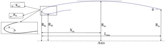
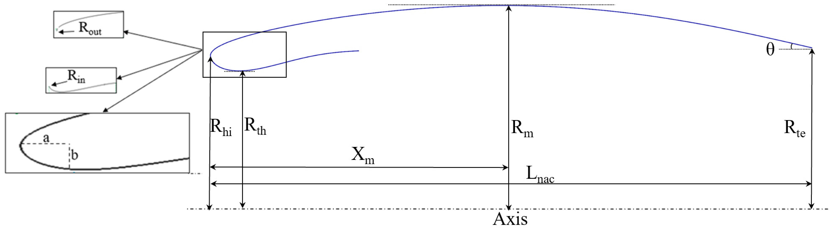
The outer contour of the nacelle is parameterized using the intuitive class/shape transformation (iCST) method [24,25], which is implemented in MATLAB R2022b. The inner contour is designed in a segmented manner: the lip section is parameterized using a super-elliptic formulation, the diffuser section is composed of two circular arcs, and the downstream flow passage behind the fan outlet is simplified as a straight, constant-area duct. The parametric design variables defining the nacelle geometry considered in this study are shown in Figure 1. These geometric parameters represent the main characteristic dimensions commonly used to describe nacelle intake profiles in previous nacelle aerodynamic design studies and are therefore adopted as the design variables in the present work. The geometric design variables are classified into two categories: outer-contour parameters and inner-contour parameters. For the outer contour, the variables include the nacelle length Lnac, the highlight radius Rhi, the outer lip radius of curvature Rout, the maximum outer radius Rm, and its corresponding axial location Xm, as well as the trailing-edge radial offset Rte and the trailing-edge angle θ relative to the nacelle axis. For the inner contour, the design variables comprise the inner lip radius of curvature Rin, the throat radius Rth, the lip contraction ratio Cr (defined as the ratio of the lip area to the throat area), and the super-elliptic aspect ratio a/b. The aerodynamic performance of the nacelle profile is ultimately assessed through trade-off analyses over the combinations of these design variables.
Figure 1.
Design variables of the nacelle profile.
The iCST parameterization for the nacelle outer contour requires nondimensionalization of the geometric variables. In this study, Lnac is selected as the reference length. The nondimensional streamwise coordinate of the external profile is denoted by X, the corresponding nondimensional radial coordinate by Y, and Rte represents the radial coordinate of the nacelle trailing edge. Based on these definitions, the class shape function of the iCST method is formulated as follows:
The nacelle outer contour exhibits the characteristics of a smooth leading edge and a sharp trailing edge, with the expression of the shape function as follows:
The general expression for the shape function is as follows:
In the above equations, N is the order of the Bernstein polynomial, represents the i-th term of the n-th order Bernstein polynomial, while bn,i denotes the coefficient of the i-th term after the function is expanded into a Bernstein polynomial, which refers to the introduced weighting coefficient. When the axial coordinate of the nacelle outer contour satisfies X = 0 and X = 1, the shape function associated with Rout and θ can be expressed as
The five nondimensional geometric parameters, namely Rout, Rte, Rm, Xm, and tanθ, together with the above constraints, determine a fourth-order Bernstein polynomial. The weighting coefficients b0 and bn are obtained from Equation (5). The remaining three weighting coefficients are determined by solving a linear system composed of the coefficient matrix in Equation (6), the constant term matrix in Equation (7), and the weighting coefficient matrix in Equation (8).
By evaluating and differentiating the shape function at the maximum radius of the nacelle outer contour, and computing its first and second derivatives at the trailing edge, the expressions for the entries of matrices A and B can be obtained. The value of the shape function S(X) at the location corresponding to the maximum radius Rm yields the following expressions for a1,n and b1:
Similarly, given that the first derivative of the shape function S(X) at the maximum radius vanishes and the second derivative at the trailing edge equals zero, the expressions for a2,n, b2, and a3,n, b3 can be derived, leading to the coefficient matrix A and the constant matrix B. The solution for the weighting coefficient matrix of the Bernstein polynomial is as follows:
The values of the five Bernstein polynomial weighting coefficients are determined through Equations (5) and (11), thereby completing the construction of the fourth-order Bernstein polynomial and yielding the corresponding coordinate values along the nacelle outer contour. With the selected six geometric parameters, the nacelle outer contour is fully defined, completing its parametric representation.
For the nacelle inner contour design, to ensure second-order geometric continuity of the lip leading-edge profile, the lip section is defined using a super-elliptic formulation. The super-ellipse is expressed as
where m and n denote the super-elliptic exponents that control the curvature distribution of the profile. In the present study, the exponents are taken as m = n = 2, under which the super-elliptic formulation reduces to a standard ellipse.
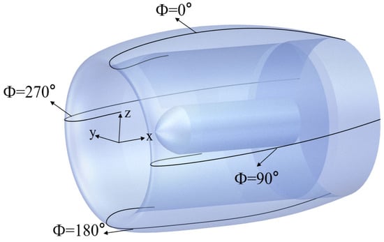
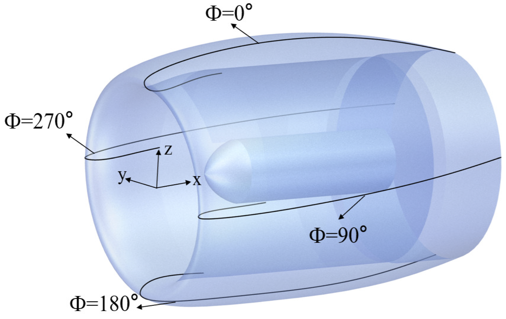
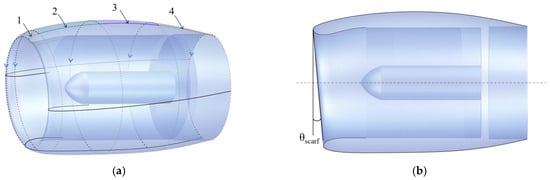
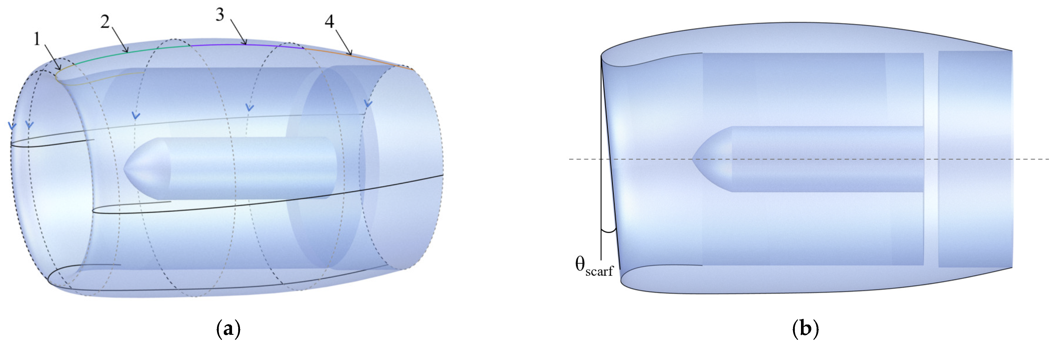
The non-axisymmetric geometry of the nacelle intake system is defined by three circumferential profiles at Φ = 0°, 90°, and 180°, as illustrated in Figure 2. The profile at Φ = 0° corresponds to the top contour of the nacelle, whereas the profiles at Φ = 90° and Φ = 180°are obtained by rotating the top profile clockwise by 90° and 180°, respectively. Owing to geometric symmetry, the profile at Φ = 90° is identical to that at Φ = 270°. Each circumferential profile is divided into four segments along the axial direction, and circular arcs connecting adjacent division points are employed as guide curves. By sweeping these guide curves, the nacelle surface is generated, resulting in the non-axisymmetric three-dimensional nacelle model shown in Figure 3a. The resulting nacelle intake features a scarfed inlet lip, whose inclination is characterized by the scarf angle θscarf, as illustrated in the side view in Figure 3b.
Figure 2.
Schematic of non-axisymmetric circumferential contours for the nacelle intake system.
Figure 3.
Schematic illustration of the non-axisymmetric nacelle geometry parameterization: (a) three-dimensional profile-sweeping strategy; (b) side view of the scarfed nacelle intake.
2.2. Numerical Methods
The numerical simulations were conducted using the commercial CFD software STAR-CCM+ 2206. A density-based coupled solver was employed to solve the compressible RANS equations. The SST k-ω turbulence model was selected. In the governing equations, the convective terms were discretized using a second-order upwind scheme, while the viscous terms were discretized using a second-order central-difference scheme. Time integration was performed using a fully implicit scheme, and the fluid properties were modeled using the ideal gas assumption. During the flow field calculations, residuals for the entire flow field and the fan inlet mass flow rate were monitored, and convergence was achieved when the residuals for each governing equation decreased below 10−5, or when the iteration residuals ceased to decrease, and the fan inlet mass flow rate remained constant.
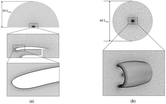
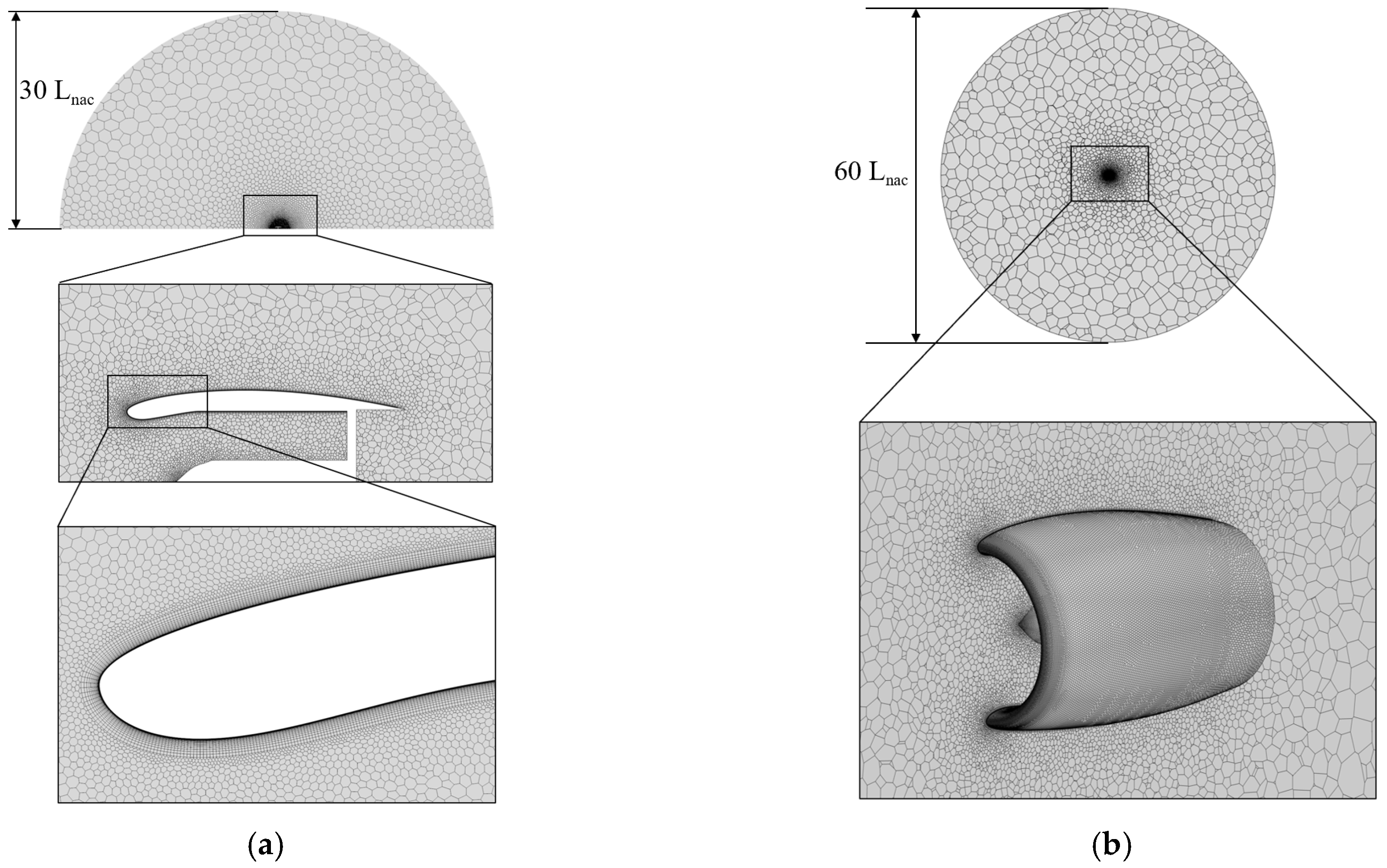
Under cruise conditions, the two-dimensional nacelle geometry and inflow were symmetric with respect to the vertical plane passing through the engine axis. To reduce computational costs, only half of the model was simulated numerically, with the computational domain being a semicircle of radius 30 Lnac. For the aerodynamic performance analysis of the three-dimensional non-axisymmetric nacelle, a spherical computational domain commonly used in wing simulations was employed, with a domain diameter set to 60 Lnac. Unstructured meshes were generated using STAR-CCM+. To accurately capture the flow characteristics near the wall, prismatic layer meshes were employed in critical regions, including the nacelle fancowl, the lip, and the intake, to provide adequate refinement of the boundary layer. This approach ensured that the height of the first mesh layer satisfied the y+ requirements of the turbulence model. The resulting two-dimensional and three-dimensional mesh structures are shown in Figure 4.
Figure 4.
Computational grids in the near-wall region for the (a) 2D and (b) 3D cases.
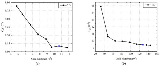
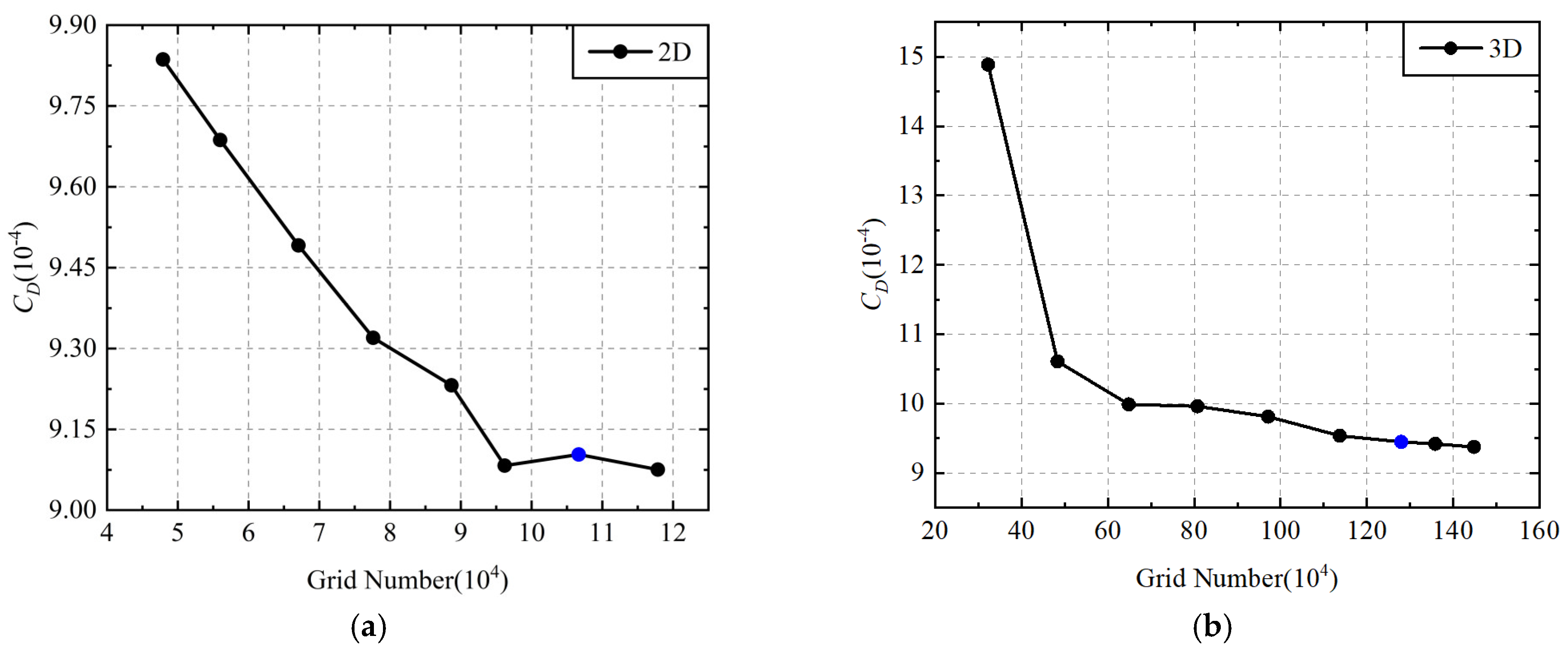
Grid independence studies were conducted for both the two-dimensional axisymmetric and three-dimensional non-axisymmetric nacelle models generated parametrically, with the results shown in Figure 5. To quantitatively assess the convergence behavior of the aerodynamic forces, the nacelle drag coefficient (CD) [26] is evaluated as
where D denotes the total drag acting on the external surface of the nacelle, denotes the freestream density, represents freestream velocity, and A signifies the reference area of the entire aircraft.
Figure 5.
Grid convergence of CD for the (a) 2D and (b) 3D cases.
For the two-dimensional calculations, the mesh size ranged from 40,000 to 130,000 elements. When the mesh size reached approximately 107,000 elements, CD became essentially stable. For the three-dimensional calculations, the mesh size varied from 300,000 to 1,500,000 elements. After the mesh size exceeded 1,280,000 elements, the variation in CD was less than 0.3%, satisfying the accuracy requirements. Based on these results, meshes with 107,000 elements for the two-dimensional simulations and 1,280,000 elements for the three-dimensional simulations were selected for subsequent numerical analyses.
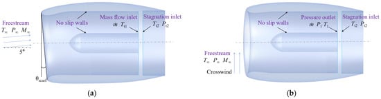
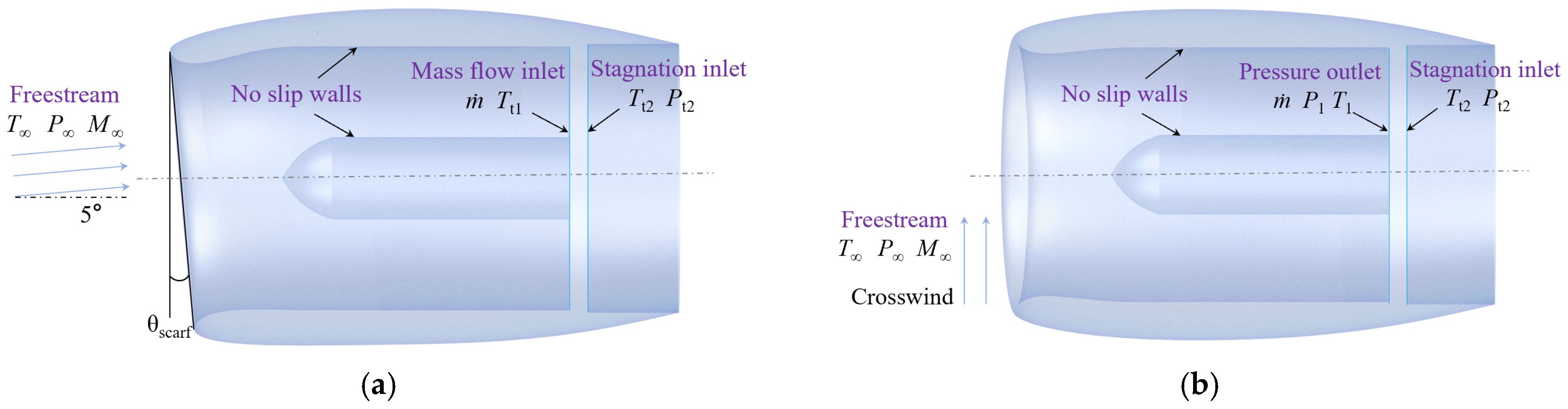
The aerodynamic simulations were performed under three representative flight conditions, namely cruise, crosswind, and maximum-lift conditions. The freestream parameters for each case were prescribed to be consistent with the corresponding flight conditions, including Mach number, angle of attack, sideslip angle, and ambient thermodynamic conditions, as summarized in Table 1. For the three-dimensional non-axisymmetric nacelle, a spherical computational domain commonly adopted in wing aerodynamic simulations was employed, with the domain diameter set to 60 Lnac. As shown in Figure 6, freestream conditions were imposed at the far-field boundary, while no-slip wall conditions were applied on the nacelle surfaces.
Table 1.
Flight conditions and boundary conditions for the cruise, crosswind, and maximum-lift.
Figure 6.
Definition of boundary conditions under (a) cruise and (b) crosswind conditions.
Considering the variation in actual mass flow rates at different circumferential locations of the realistic non-axisymmetric nacelle, the flow conditions for three representative cross-sections were determined according to the scarf angle θscarf: Φ = 0°, ṁ = 59.675 kg/s; Φ = 90°, ṁ = 64.265 kg/s; Φ = 180°, ṁ = 68.856 kg/s. To represent the aerodynamic influence of the engine on the intake flow, appropriate boundary conditions were imposed at the fan–face plane. At the engine inlet, stagnation inlet boundary conditions were specified using the prescribed total temperature and total pressure. Depending on the operating condition, the engine demand was modeled using either a mass-flow-related boundary condition or a pressure-based outlet condition, allowing the intake flow to respond to the suction effect generated by the engine.
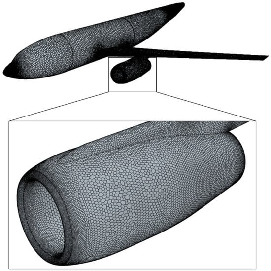
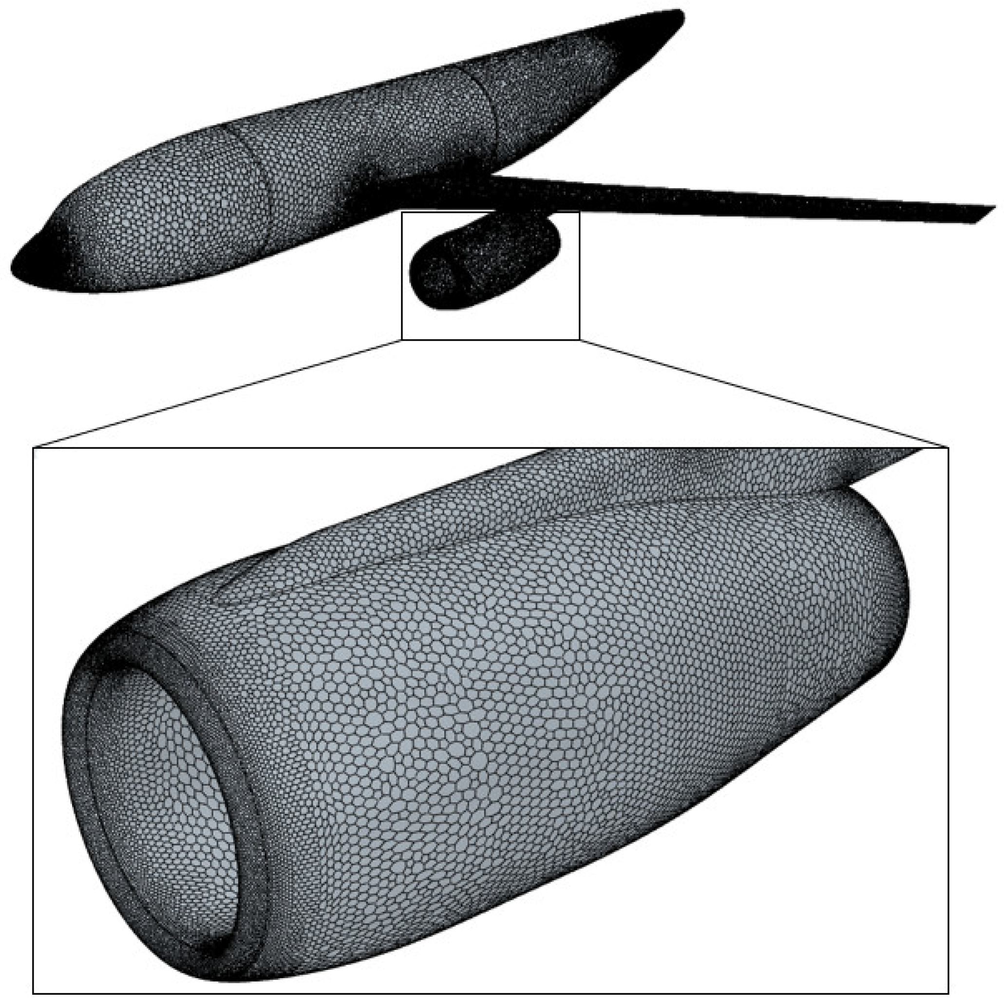
To validate the accuracy and effectiveness of the numerical method, numerical simulations were performed for the standard civil aircraft high-speed cruise benchmark, the DLR-F6 configuration [27], under cruise conditions. The numerical results were compared with the corresponding experimental data obtained from the publicly available wind-tunnel database of the AIAA Drag Prediction Workshop. The computations employed the same grid generation strategy described above, and the mesh for the DLR-F6 configuration is shown in Figure 7. The simulations were conducted under the same freestream conditions as the wind-tunnel experiments, including the Mach number and angle of attack, with the corresponding boundary conditions summarized in Table 2. The turbulence model used in the simulations remained consistent with the previous discussion.
Figure 7.
Overall and detailed views of the computational grid for the DLR-F6 configuration.
Table 2.
Boundray conditions of the DLR-F6 configuration.
The pressure coefficient Cp is defined as follows:
where P denotes the local static pressure, and P∞ signifies the freestream static pressure.
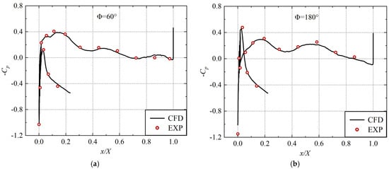
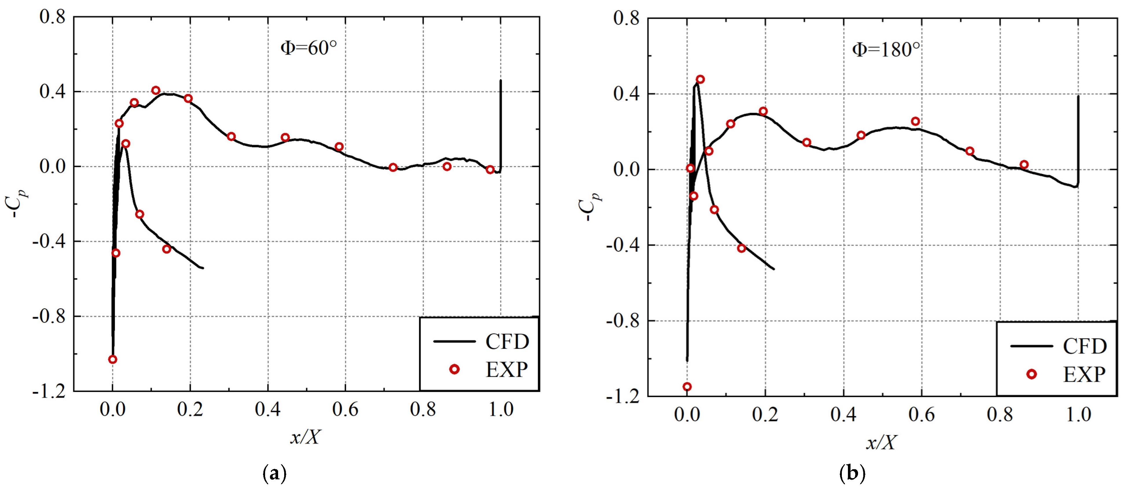
Based on this definition, Figure 8 presents the distribution of −Cp (the negative pressure coefficient) at different nacelle cross-sectional locations. The experimental data used for comparison were obtained from the publicly available wind-tunnel database of the DLR-F6 configuration provided by the AIAA Drag Prediction Workshop [27]. The numerical results show good agreement with the experimental measurements, with accurate prediction of both the pressure peak location and magnitude. This demonstrates the reliability of the numerical methodology and boundary condition setup adopted for the nacelle simulations in this study.
Figure 8.
Comparison of CFD and experimental pressure distributions at multiple nacelle profiles at 60° (a) and 180° (b) [27].
3. Optimization Methodology
3.1. Methodology of Surrogate-Based Optimization
To enhance the efficiency of the aerodynamic design optimization process for nacelles, this study employed Siemens HEEDS 2021 optimization software and introduced key performance models to evaluate the aerodynamic optimization results. Two-dimensional and three-dimensional Kriging models were then established to enable rapid prediction of nacelle aerodynamic performance and comprehensive exploration of the design space. An automated workflow integrating parametric modeling, CFD simulations, and aerodynamic performance evaluation was developed to generate feasible design candidates. During the optimization process, Siemens HEEDS iteratively updated the optimization parameters and fed them back to MATLAB, progressively expanding the sample database. For the MOO problem, the NSGA-II genetic algorithm implemented in Siemens HEEDS was employed to identify the optimal solution set of multi-objective problems, ultimately obtaining the Pareto front across multiple operating conditions and objectives.
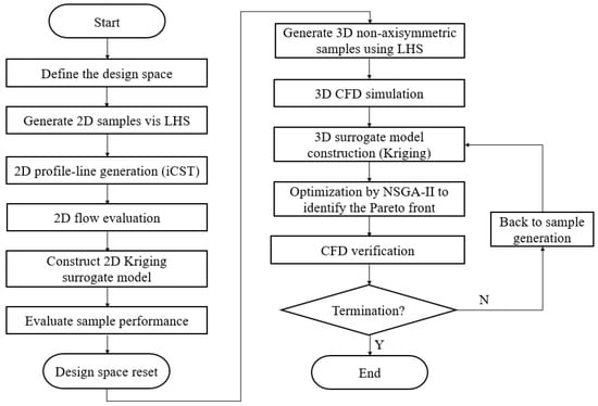
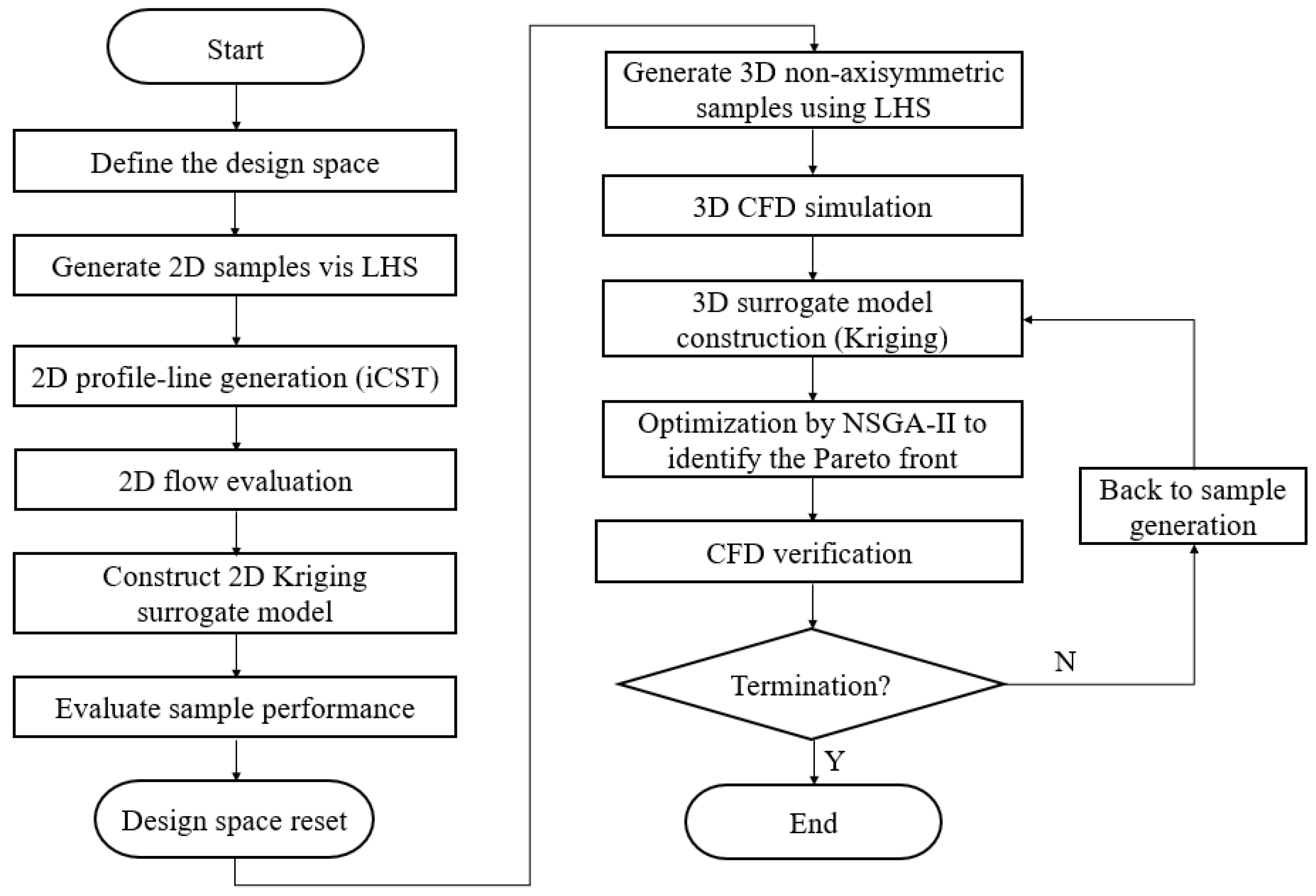
Figure 9 illustrates the integrated adaptive MOO framework based on Kriging surrogate models. The framework consists of sampling methods, parametric geometry definition, automatic mesh generation, nacelle aerodynamic performance evaluation, surrogate models, and optimization algorithms. Initially, the Latin Hypercube Sampling (LHS) method is applied to select samples within the two-dimensional design space. Next, CFD methods are utilized to assess the aerodynamic performance of the samples. Based on this, a Kriging surrogate model is constructed to enable rapid performance prediction, and promising two-dimensional configurations are identified to reduce the three-dimensional design space. Subsequently, under prescribed circumferential distribution constraints, non-axisymmetric three-dimensional samples are generated using LHS. CFD simulations are then performed to obtain the aerodynamic performance of the samples under different operating conditions, and the Kriging surrogate model is employed to achieve rapid prediction of three-dimensional aerodynamic performance. The NSGA-II algorithm is used to identify the Pareto front. Finally, numerical simulations are performed to validate the optimization results, and the sample dataset is iteratively updated until the termination criteria are satisfied.
Figure 9.
Optimization design process.
3.2. Key Aerodynamic Performance Metrics
During the optimization of the nacelle intake system, different aerodynamic performance metrics are adopted for different operating conditions. Under cruise conditions, CD is considered as the primary performance indicator because it directly affects aircraft fuel consumption. For off-design operating conditions, such as crosswind and maximum-lift operations, the internal flow quality of the intake becomes more critical. In these conditions, the intake total pressure recovery coefficient (σ) and the tendency of inlet flow separation are used to evaluate the aerodynamic performance of the intake system. Based on the iCST parameterization method, a systematic framework for nacelle geometry parameterization is developed, enabling the generation of extensive two-dimensional and three-dimensional geometric profile sample databases.
σ is an important metric for characterizing the aerodynamic performance of the nacelle intake, representing the total pressure loss of the airflow during the diffusion process. In this study, the evaluation of total pressure loss follows the methodology presented in a referenced engineering technical report [28]. The assessment accounts for the primary contributors to total pressure loss, including lip loss, diffuser loss, straight-duct loss, flow blockage loss, interaction loss between the intake duct and the diffuser, and internal friction loss within the intake duct. The total pressure recovery coefficient can therefore be expressed as
where denotes the total pressure loss associated with flow separation at the intake lip, represents the diffuser loss evaluated under the assumption that the interaction between the inlet flow and the diffuser is neglected, N is an amplification factor accounting for the effect of inlet flow distortion, and correspond to the correction terms for constant-area duct losses in the upstream and downstream duct sections of the diffuser, respectively.
The nacelle drag is evaluated following the methodology proposed by Zhang et al. [29]. In the two-dimensional simulations, the drag calculation accounts for the actual mass flow rates at different locations, thereby improving the accuracy of the drag prediction. To quantify the effects of geometric parameters on nacelle drag characteristics, a Kriging-based aerodynamic response surface model for CD is developed. Representative sample points are first generated within the design space using LHS. A global sensitivity analysis is then performed to evaluate the relative importance of the input parameters and identify the key geometric variables that significantly influence CD, including Lnac, Rhi, Rout, Rm, Xm, Rte, and θ.
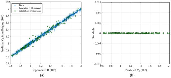
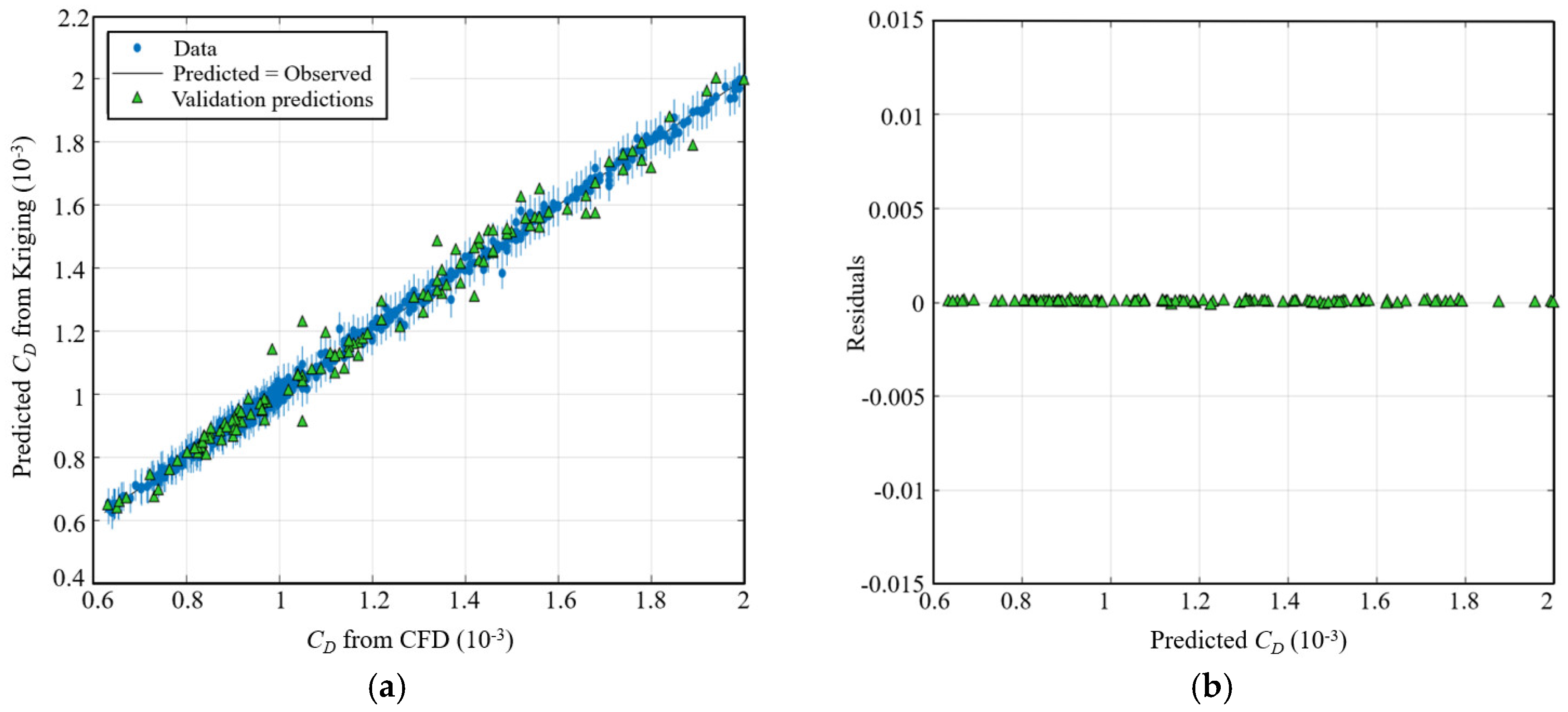
An automated workflow is implemented to perform batch CFD simulations for the entire sample database. The CD values on the nacelle outer surface are extracted, resulting in a total of 910 valid samples. Based on these data, the Kriging-based aerodynamic response surface model of CD is constructed, as illustrated in Figure 10. During model development, 80% of the samples are randomly selected for training, while the remaining 20% are reserved for validation. The results demonstrate that the surrogate model exhibits strong consistency for both the training and validation datasets. The predicted CD values show excellent agreement with the CFD results, and the prediction errors are small and uniformly distributed over the entire CD range, clustering around zero. These findings indicate that the proposed response surface model achieves high predictive accuracy and is well-suited for subsequent nacelle aerodynamic optimization studies.
Figure 10.
Validation of the Kriging surrogate model for CD: (a) comparison between Kriging predictions and CFD results; (b) residuals of the validation samples.
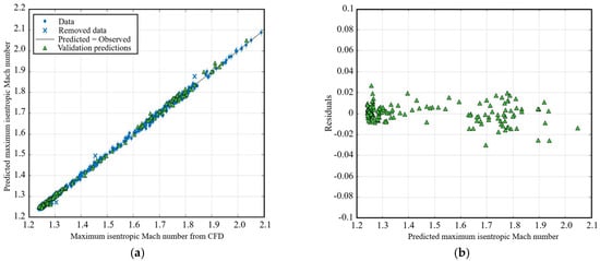
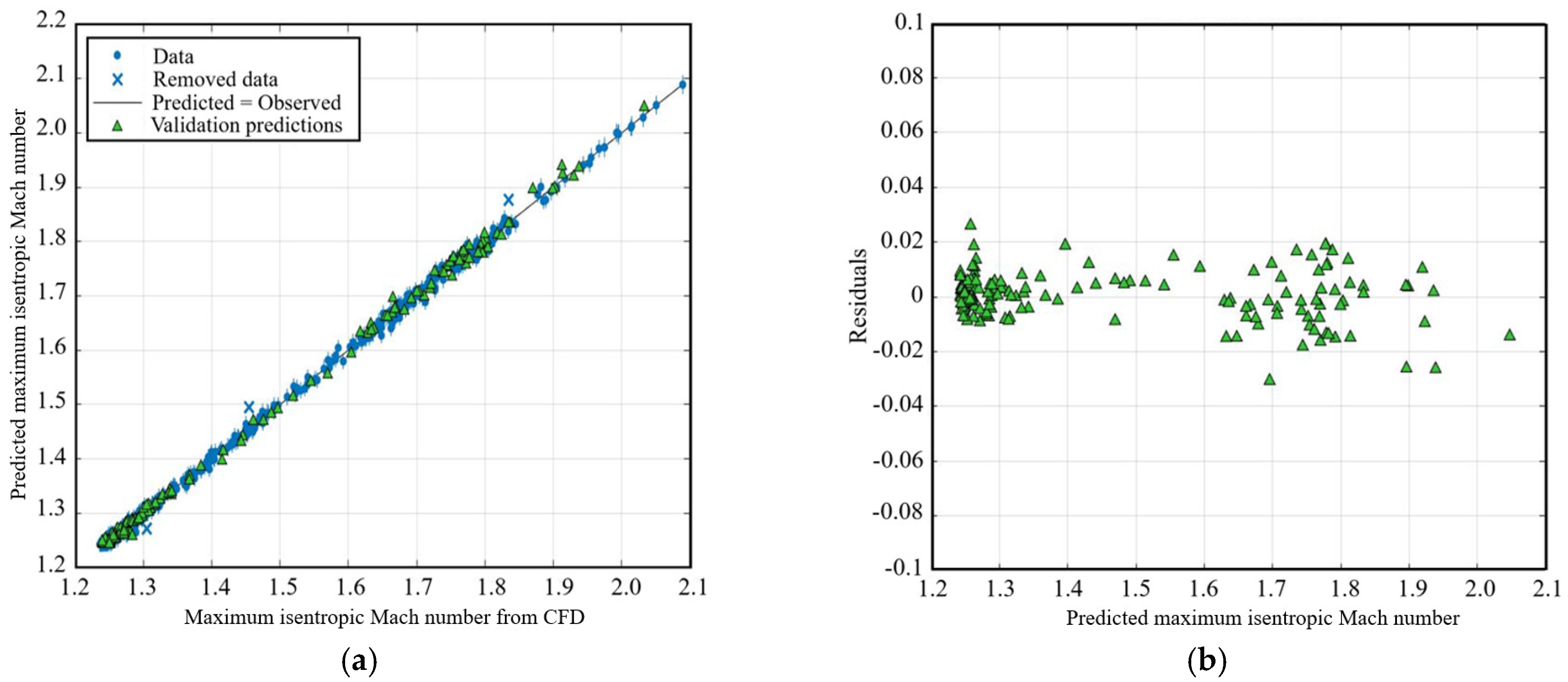
Variations in nacelle geometric parameters have a pronounced impact on inlet flow separation characteristics. Since local flow acceleration and adverse pressure gradients within the inlet are commonly associated with the onset of flow separation, the maximum isentropic Mach number along the 270° circumferential line of the short nacelle is selected as a representative metric to characterize the tendency of inlet flow separation. Consistent with the preceding analysis, a Kriging-based response surface model describing inlet flow separation characteristics is constructed using 780 samples. Based on the sensitivity analysis, the dominant geometric parameters affecting flow separation are identified as Rin, Rth, Cr, a/b, and Rout.
The predicted maximum isentropic Mach numbers along the 270° circumferential line obtained from the Kriging-based aerodynamic response surface model are compared with the corresponding CFD results in Figure 11, along with the residual distributions of the validation samples. The results show that the predicted values for both the training and validation datasets are closely distributed around the diagonal, with no evident systematic bias. This indicates that the surrogate model accurately captures the overall variation in the maximum isentropic Mach number along the 270° circumferential line with respect to changes in geometric parameters. Further residual analysis reveals that the prediction errors are generally confined within 0.02, with noticeable dispersion occurring only in localized high-Mach-number regions. Overall, the predictive accuracy of the model meets the engineering requirements for inlet system optimization.
Figure 11.
Validation of the Kriging surrogate model for the maximum isentropic Mach number along the 270° nacelle profile: (a) comparison between Kriging predictions and CFD results; (b) residuals of the validation samples.
Block fuel associated with the nacelle is defined as the increment in fuel burn during the block time resulting from aerodynamic drag and additional system loads introduced by the engine nacelle installation, and it represents an important metric in aircraft aerodynamic optimization. In this study, the block fuel consumption calculation module implemented in the Simcenter Amesim platform is adopted to evaluate the mission fuel consumption associated with different nacelle configurations.
Within this framework, the propulsion system is represented using a simplified turbofan engine model. The instantaneous fuel mass flow rate is determined from the throttle setting in the engine model and is assumed to vary linearly with the throttle signal:
where is the fuel mass flow rate, denotes the maximum fuel flow rate at full throttle, and throttle denotes the normalized throttle setting.
Based on the conservation of momentum across the propulsion system control volume, the engine thrust is computed as
where F is the engine thrust, is the core airflow mass flow rate, is the exhaust jet velocity, is the freestream velocity, and denote the nozzle exit pressure and ambient pressure, respectively, and is the nozzle exit area.
The specific fuel consumption (SFC) is defined as
The block fuel consumption for the mission is obtained by integrating the instantaneous fuel flow rate over the mission duration
where denotes the total fuel consumed during the mission and tmission represents the mission duration.
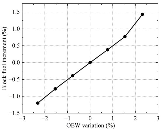
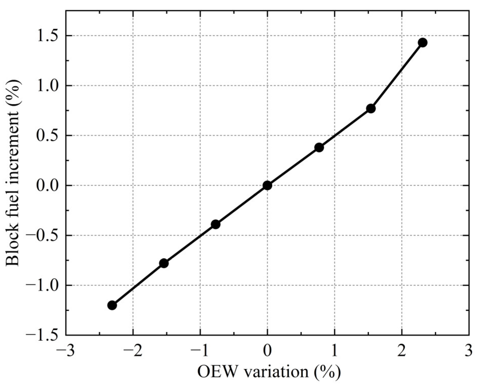
In the mission analysis, the nacelle drag coefficient CD and structural weight corresponding to different configurations are introduced as input parameters. The nacelle weight is estimated using an engineering-based method derived from the inner and outer duct mass flow rates and cross-sectional areas [30]. Since only inlet geometric parameters are varied in this study, the exhaust duct geometry and mass flow rate are assumed to remain constant. The resulting influence of inlet-induced nacelle weight variations on block fuel consumption is illustrated in Figure 12. For a reference operating empty weight (OEW) of 130,000 kg, a 2.3% increase in OEW results in approximately a 1.43% increase in block fuel consumption, indicating that inlet-induced weight variations have a measurable but limited impact on the overall fuel burn.
Figure 12.
Effect of relative OEW variation on block fuel increment.
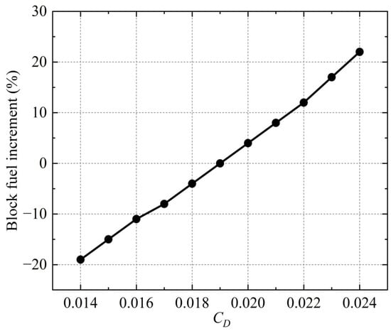
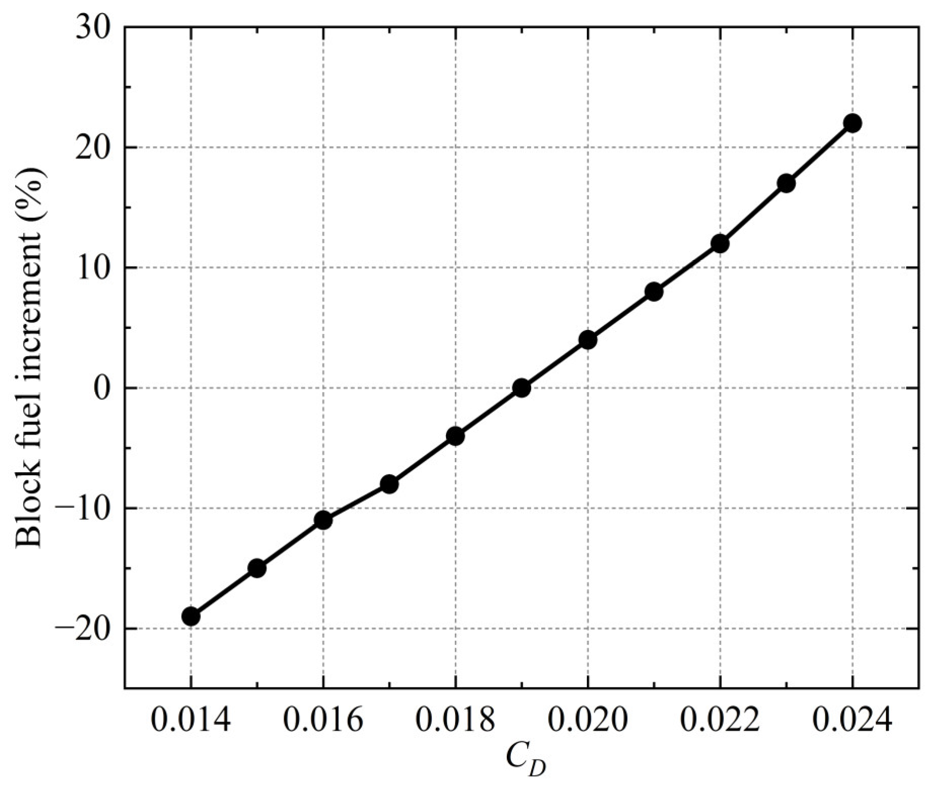
Based on the aerodynamic response surface model established in the preceding section, the variation in CD with respect to different geometric parameters is obtained. Taking a mission range of 4300 km and a block fuel consumption of 25,846 kg as the baseline condition, the influence of variations in CD on block fuel consumption under cruise conditions at an altitude of 11.8 km and a Mach number of 0.85 is illustrated in Figure 13. The results indicate that the increment in block fuel consumption exhibits an approximately linear and monotonic increase with increasing CD. Relative to the reference case, a reduction in CD by 0.005 leads to an approximately 19% decrease in block fuel consumption, demonstrating that aerodynamic drag is the dominant factor governing variations in block fuel consumption.
Figure 13.
Effect of CD on the block fuel increment.
3.3. Multi-Objective Optimization
Within the HEEDS platform, the ranges of the design variables are prescribed, and more than one thousand initial samples are generated using LHS to establish the initial design space. First, this research performs rapid evaluations based on two-dimensional parameterized nacelle geometry samples. The effects of geometric parameter variations on aerodynamic performance are examined through a combined consideration of drag constraints, total pressure recovery, and flow separation characteristics. Accordingly, the two-dimensional design space is further screened and constrained, leading to the identification of ranges of two-dimensional geometric parameters that satisfy the integrated aerodynamic performance requirements, as summarized in Table 3, which provides a rational and well-defined parameter space for three-dimensional optimization.
Table 3.
Design variable bounds.
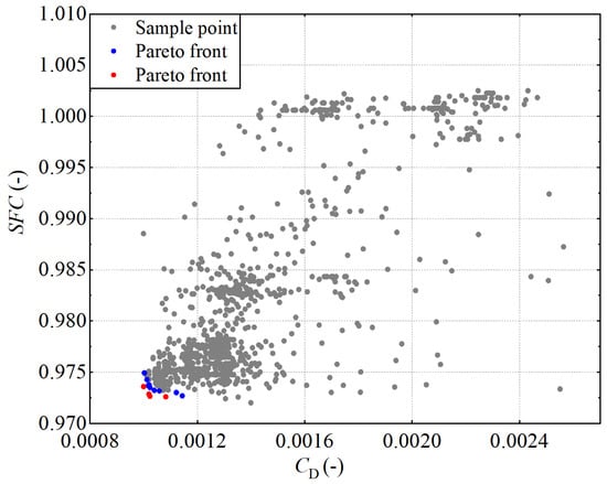
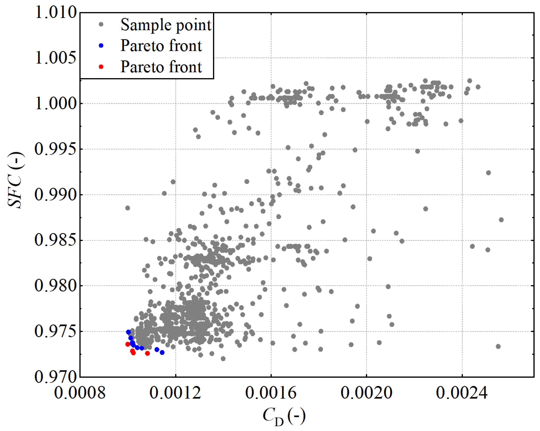
As shown in Figure 14, the Pareto frontiers and the corresponding performance distributions obtained at different iterations during the MOO of the three-dimensional nacelle aerodynamic shape are presented. The gray markers denote all evaluated sample points in the design space. The blue markers denote the non-dominated solution set obtained in the penultimate iteration, whereas the red markers represent the non-dominated solutions after convergence in the final iteration. As the optimization proceeds, the non-dominated solutions progressively approach the Pareto frontier in the objective space, with the overall performance distribution shifting toward more favorable regions. Compared with the penultimate iteration, the solution set in the final iteration exhibits a more compact distribution in terms of multi-objective performance, accompanied by a pronounced reduction in dispersion among non-dominated solutions, indicating that the design space has been sufficiently explored in the later stages of the optimization and that a stable Pareto frontier has been achieved. It should be noted that the optimization process was performed within the integrated HEEDS platform using Kriging surrogate models coupled with the NSGA-II algorithm, allowing most candidate designs to be evaluated efficiently through surrogate predictions and thereby significantly reducing the overall computational cost of the optimization process.
Figure 14.
Distribution of evaluated design samples and Pareto fronts for the three-dimensional nacelle multi-objective optimization.
4. Discussion
Based on the Pareto frontiers obtained from the MOO results in Section 3, representative optimized configurations are selected from the non-dominated solution set, and their aerodynamic performances are comparatively analyzed to assess the overall performance of the optimized designs under different operating conditions.
4.1. Analysis at Cruise Condition
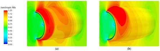
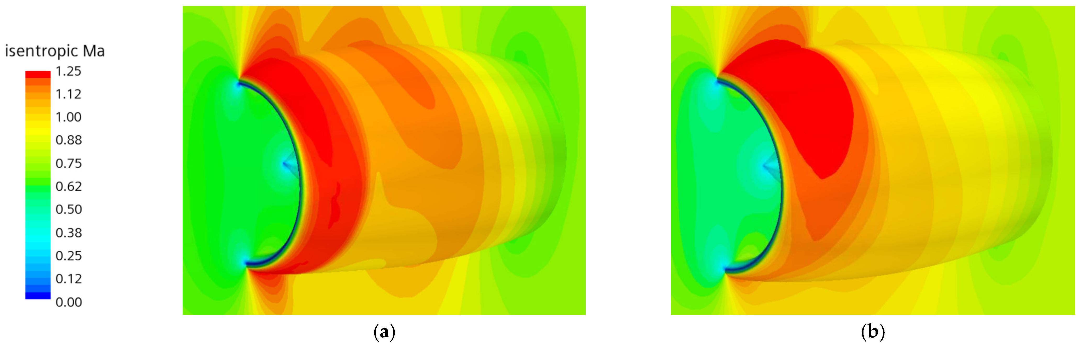
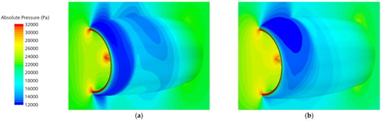
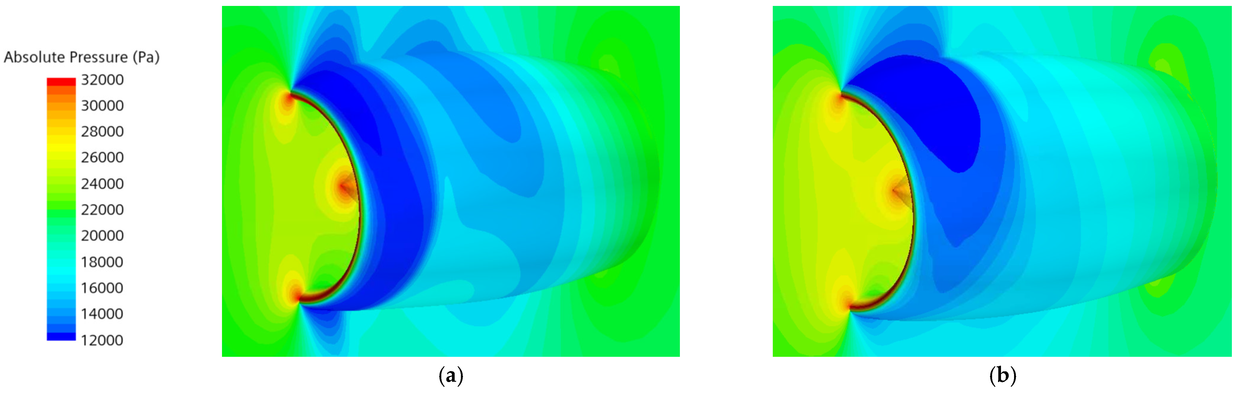
Compared with the baseline configuration, the optimized design achieves a reduction of 0.933% in CD, accompanied by a 0.628% decrease in fuel consumption. The surface distributions of the isentropic Mach number and static pressure for the baseline and optimized nacelle configurations are shown in Figure 15 and Figure 16, respectively. For the external flow field of the nacelle, both configurations exhibit locally supersonic flow over the nacelle surface. In the optimized configuration, the supersonic region near the nacelle leading edge is reduced, accompanied by a pronounced weakening of the supersonic flow along the midsection of the nacelle.
Figure 15.
Comparison of isentropic Mach number distributions on the nacelle surface and symmetry plane for (a) the baseline and (b) the optimized configurations.
Figure 16.
Comparison of absolute pressure distributions on the nacelle surface and symmetry plane for (a) the baseline and (b) the optimized configurations.
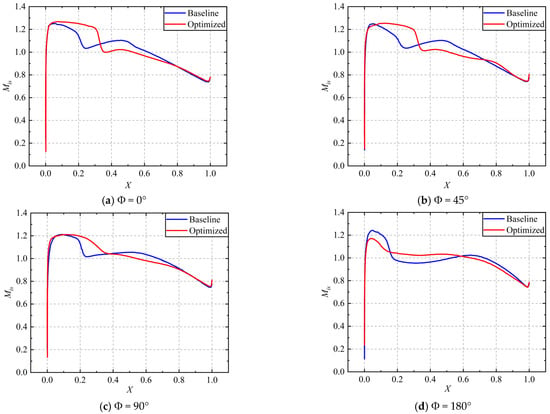
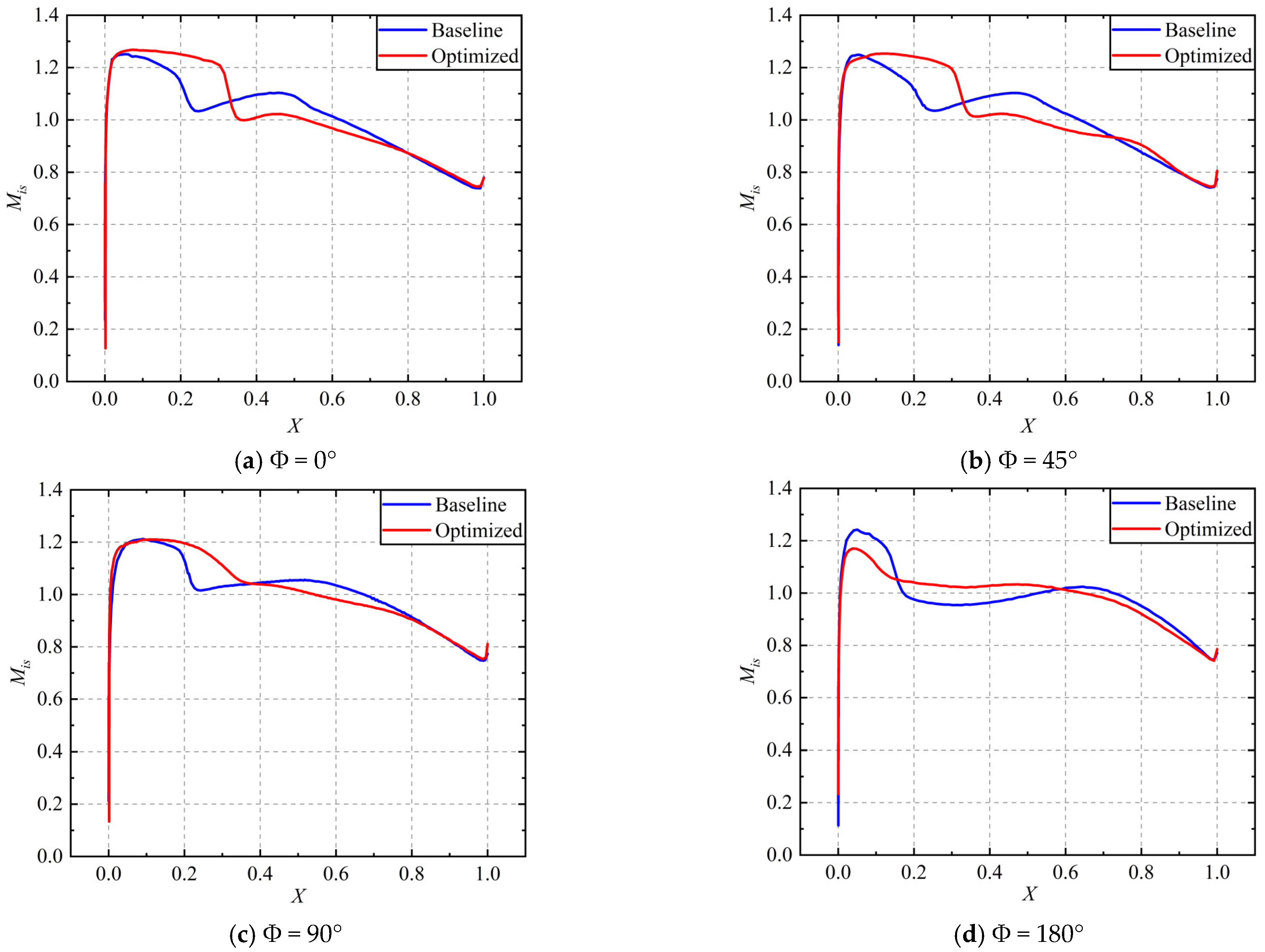
As shown in Figure 17, the isentropic Mach number distributions on the outer cowl at four nacelle cross-sections exhibit significant differences between the baseline and optimized configurations. For the upper aerodynamic profiles corresponding to Φ = 0°and Φ = 45°, the overall flow characteristics are relatively similar. Along the upper aerodynamic profile, shock formation is observed at X = 0.14 for the baseline configuration, whereas in the optimized configuration, a strong shock develops at X = 0.24 following an initial acceleration process. At the Φ = 45° section, the shock location moves downstream to X = 0.24 in the optimized design. These results indicate that the optimized configuration improves the flow characteristics by delaying shock formation, thereby reducing shock-induced drag.
Figure 17.
Distributions of the isentropic Mach number along the axial direction at selected circumferential positions for the baseline and optimized configurations.
For the Φ = 90° cross-section, the baseline configuration exhibits a pronounced shock at X = 0.20, whereas the optimized configuration shows a smoother distribution of the isentropic Mach number. This leads to a more uniform flow over the nacelle, which is conducive to reducing both external shock-induced drag and skin-friction drag. At the Φ = 180° cross-section, a distinct shock appears at X = 0.10 in the baseline configuration. In contrast, the optimized configuration reduces the maximum isentropic Mach number from 1.24 to 1.17, accompanied by a smoother Mach number distribution, thereby further enhancing the aerodynamic performance of the nacelle outer surface.
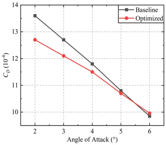
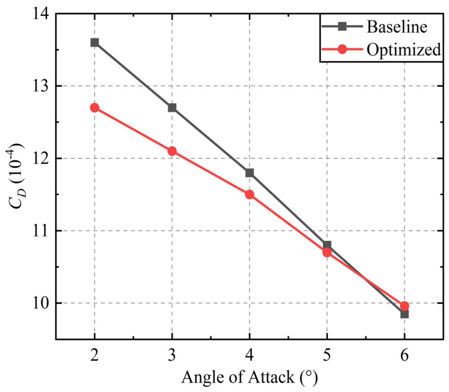
The variation in CD for the baseline and optimized configurations across a range of angles of attack is shown in Figure 18. Over the range investigated, the optimized configuration exhibits a more gradual variation in CD, indicating reduced sensitivity to changes in angle of attack. Within the low angle-of-attack region, the optimized configuration shows a noticeable reduction in CD, with a reduction of 6.62% at an angle of attack of 2°. It is noteworthy that at an angle of attack of 6°, the CD of the optimized configuration is marginally higher than that of the baseline model. This phenomenon may be attributed to alterations in flow separation characteristics as the angle of attack increases.
Figure 18.
Variation in CD with angle of attack for the baseline and optimized configurations.
4.2. Analysis at Crosswind Condition
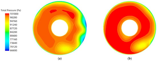
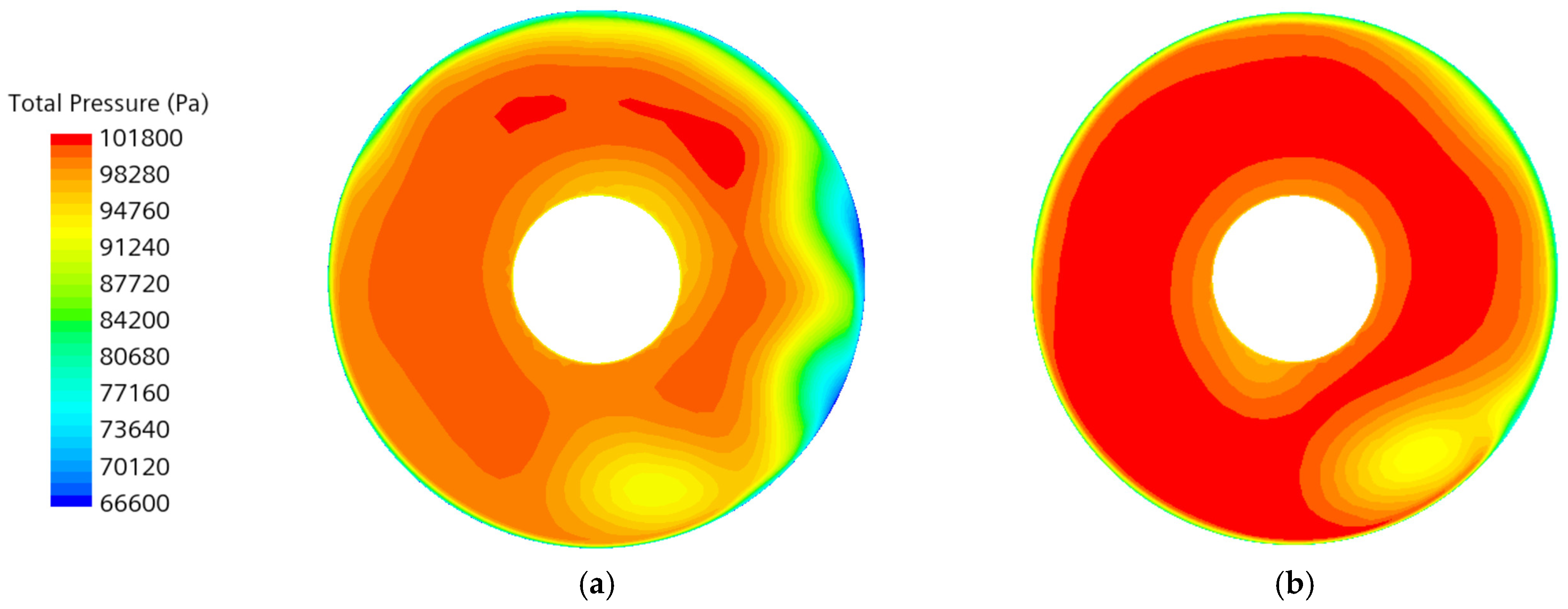
The total pressure distributions at the fan face for different nacelle configurations under crosswind conditions are shown in Figure 19. The baseline configuration exhibits a pronounced low-pressure region on the fan inflow plane, mainly caused by flow separation induced by the crosswind. In addition, due to the combined effects of crosswind and ground interaction, both configurations develop a distinct low-pressure band in the lower windward region of the fan inflow plane, indicating the formation of a ground vortex. Compared with the baseline configuration, the optimized configuration shows a more uniform total pressure distribution at the fan face, with a significantly reduced low-pressure region, which helps mitigate total pressure losses and improve flow stability.
Figure 19.
Fan face total pressure contours under crosswind conditions for (a) the baseline and (b) the optimized configurations.
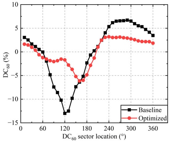
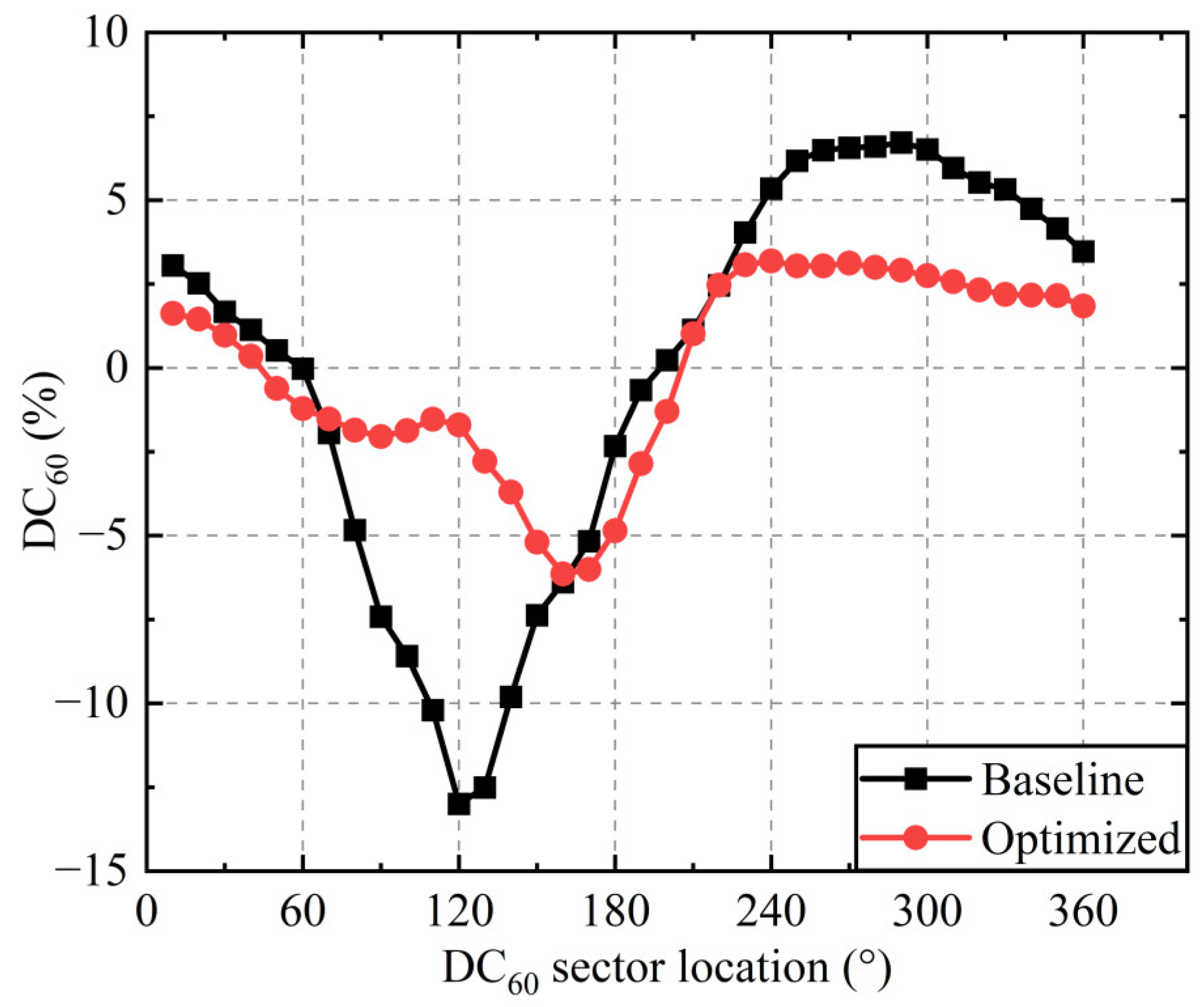
The circumferential distribution of DC60 is shown in Figure 20, where it is defined as
where P60min refers to the average total pressure over the 60° fan–face sector with the minimum mean total pressure, represents the area-averaged total pressure over the entire fan inlet plane, and q denotes the dynamic pressure.
Figure 20.
Circumferential distribution of the distortion index DC60 at the fan face for the baseline and optimized configurations.
The results indicate that regions of total pressure loss at the fan face are mainly concentrated on the windward-side. A comparison between the two configurations reveals that the baseline configuration exhibits a noticeably higher overall distortion level than the optimized configuration. Notably, the DC60 value of the baseline configuration begins to decrease near Φ = 120°, whereas the optimized configuration maintains an increasing DC60 trend over the sector spanning approximately Φ = 120° to 150°. This difference can be attributed to the more severe flow separation in the baseline configuration, which leads to substantial total pressure losses, while flow separation is mitigated in the optimized configuration. Consequently, the contribution of ground-vortex-induced losses in the lower windward region becomes comparatively more significant, thereby affecting the circumferential evolution of DC60. In conjunction with Figure 19, it is evident that the pressure loss associated with the ground vortex remains smaller than that caused by windward-side flow separation. Over the entire fan–face circumference, the DC60 values of the baseline configuration range from −13% to 6.7%, corresponding to σ = 95.17%, whereas those of the optimized configuration are confined to a narrower range of −6.1% to 3.2%, with σ increased to 97.93%. Overall, the optimized configuration substantially alleviates both the magnitude and spatial extent of total pressure distortion, resulting in a more uniform inflow at the fan face.
4.3. Analysis at the Maximum-Lift Coefficient Condition
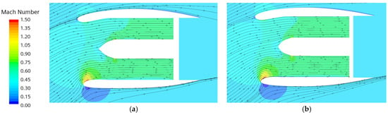
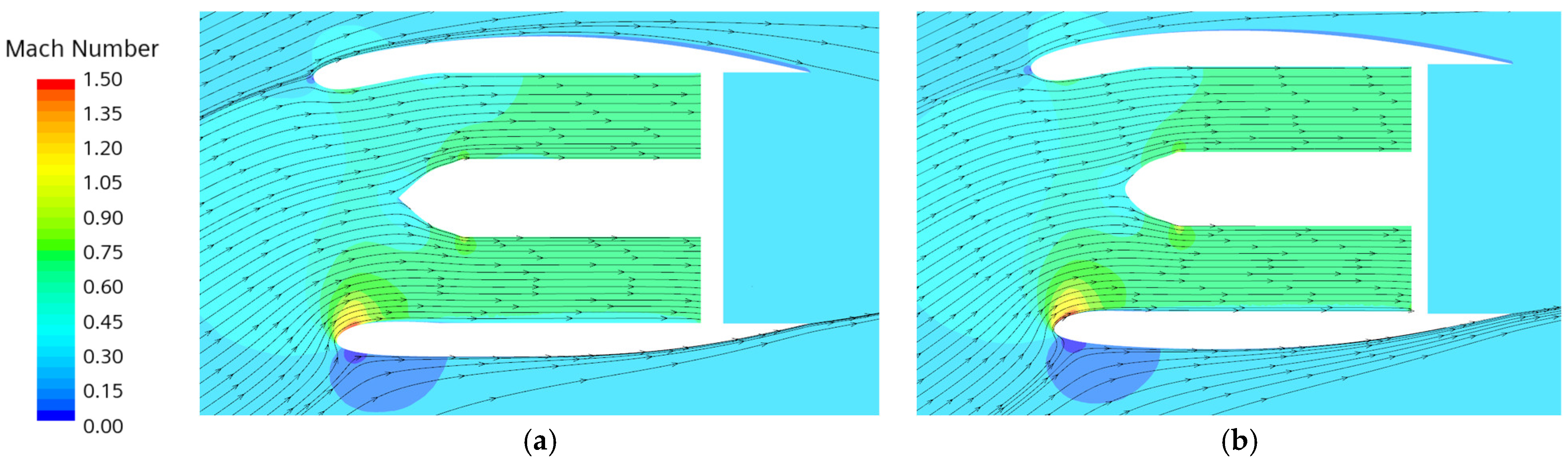
The Mach number distributions of the flow field on the symmetric nacelle cross-section under the maximum-lift coefficient condition are shown in Figure 21. It can be observed that the baseline and optimized configurations exhibit similar flow characteristics under this operating condition. Owing to the high angle of attack, the stagnation point of the incoming flow is located on the outer surface of the lower lip, while pronounced acceleration occurs within the lower lip region, giving rise to locally supersonic flow. The flow passes uniformly through the inlet and reaches the fan face in a uniform manner, with no evidence of flow separation.
Figure 21.
Contours of the Mach number on the symmetric plane for (a) the baseline and (b) the optimized configurations.
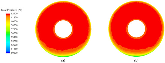
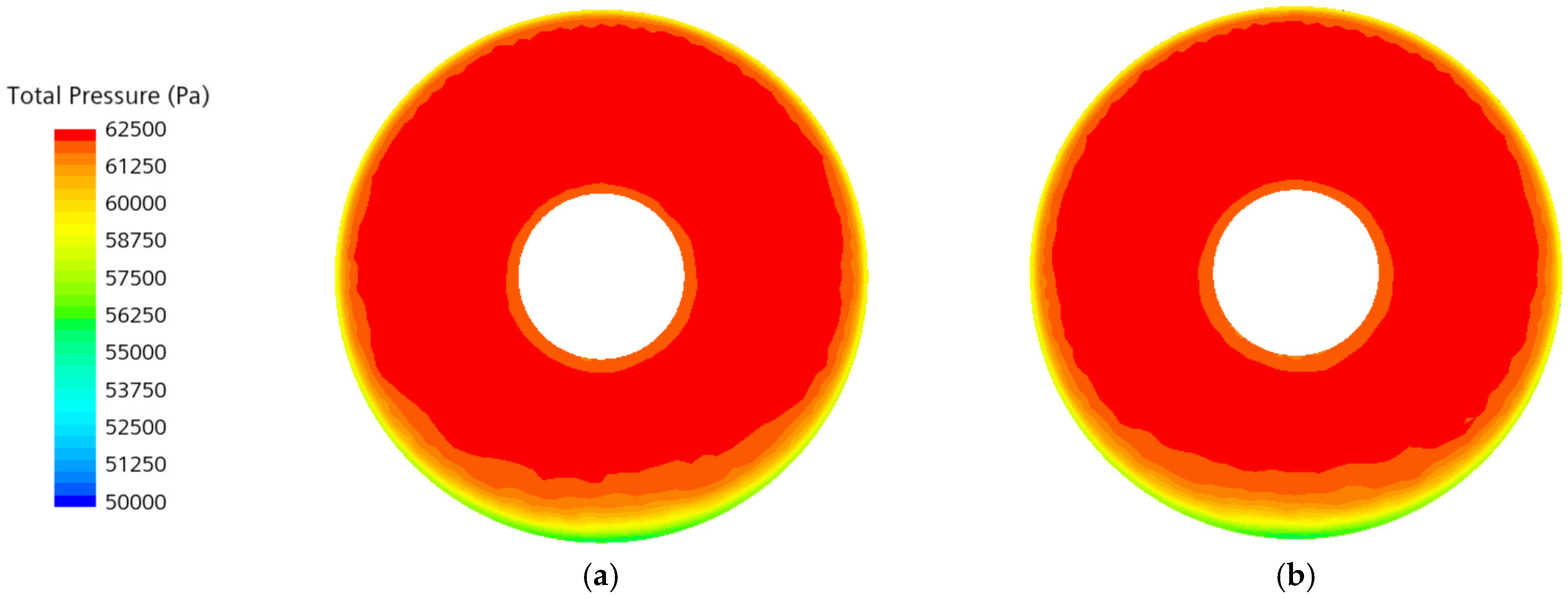
Figure 22 illustrates the total pressure distributions at the fan face for different nacelle configurations under the maximum-lift coefficient condition. Under this inflow condition, regions of total pressure loss are primarily concentrated in the lower portion of the fan face. σ exceeds 99% for both configurations, thereby satisfying the requirements for stable engine operation. Therefore, compared with the baseline configuration, the optimized configuration preserves the favorable aerodynamic performance of the baseline configuration under the maximum-lift condition.
Figure 22.
Fan face total pressure contours under maximum-lift conditions for (a) the baseline and (b) the optimized configurations.
5. Conclusions
This study develops an integrated multi-objective optimization methodology for the aerodynamic design of civil aircraft nacelle intake systems. By coupling parametric geometric modeling, CFD-based numerical analysis, and the Siemens HEEDS optimization platform, a multi-objective optimization of nacelle intake profiles is carried out using Kriging surrogate models and the NSGA-II genetic algorithm. The main conclusions are summarized as follows.
- (1)
- An intuitive class–shape transformation (iCST)–based parameterization method is employed to construct a geometric parameterization model for nacelle intake profiles. The model is applied to both two-dimensional axisymmetric and three-dimensional non-axisymmetric optimization designs, providing a reliable geometric modeling foundation for aerodynamic analysis and multi-objective optimization.
- (2)
- To enable rapid aerodynamic performance evaluation, key geometric parameters that have significant influences on aerodynamic drag, inlet distortion, and flow separation are identified and screened. Two-dimensional numerical simulations are used to perform fast assessments of intake profiles, allowing efficient prediction of aerodynamic performance and global exploration of the two-dimensional design space, thereby reducing the design space for subsequent three-dimensional optimization.
- (3)
- In the three-dimensional non-axisymmetric optimization, both cruise and off-design operating conditions are considered. The optimization objectives include block fuel consumption under cruise conditions, as well as inlet distortion and flow separation under off-design conditions. The results indicate that block fuel consumption is primarily affected by variations in aerodynamic drag, while the influence of geometry-induced weight changes is relatively limited. CFD validation of the Pareto-optimal solutions predicted by the Kriging surrogate model shows that, compared with the baseline configuration, the optimized nacelle achieves a 0.933% reduction in CD and a 0.628% decrease in block fuel consumption during cruise conditions. Under crosswind conditions, σ of the optimized configuration is increased by 2.76%, accompanied by a noticeable reduction in flow separation. At the maximum-lift coefficient condition, the inlet total pressure recovery remains above 99%, demonstrating coordinated aerodynamic performance improvements of the nacelle across multiple operating conditions. Although NSGA-II was adopted in this study due to its robustness and wide application in multi-objective optimization, future work will further compare its performance with other advanced multi-objective optimization algorithms for this specific nacelle design problem.
Author Contributions
Conceptualization, H.L. and M.Z.; Methodology, H.L. and B.H. (Baoe Hong); Software, H.L. and J.J.; Validation, H.L., B.H. (Bihai He) and C.C.; Investigation, H.L. and J.J.; Data curation, H.L.; Writing—original draft, H.L.; Writing—review and editing, M.Z. and B.H. (Baoe Hong); Project administration, M.Z. All authors have read and agreed to the published version of the manuscript.
Funding
This research was funded by the Joint Research Fund of Shanghai Commercial Aircraft Systems Engineering Science and Technology Innovation Center.
Data Availability Statement
The datasets used and analyzed during the current study are available from the author on reasonable request.
Conflicts of Interest
Authors Hao Liu and Jintao Jiang were employed by the company Commercial Aircraft Corporation of China, Ltd. The remaining authors declare that the research was conducted in the absence of any commercial or financial relationships that could be construed as a potential conflict of interest.
Abbreviations
The following abbreviations are used in this manuscript:
| AOA | angle of attack |
| CFD | computational fluid dynamics |
| iCST | intuitive class shape transformation |
| LHS | Latin hypercube sampling |
| MOO | multi-objective optimization |
| NSGA-II | non-dominated sorting genetic algorithm II |
| OEW | operating empty weight |
| RANS | Reynolds-Averaged Navier–Stokes |
| SFC | specific fuel consumption |
References
- Bravo-Mosquera, P.D.; Catalano, F.M.; Zingg, D.W. Unconventional aircraft for civil aviation: A review of concepts and design methodologies. Prog. Aerosp. Sci. 2022, 131, 100813. [Google Scholar] [CrossRef] [Scilit]
- Xue, R.; Jiang, J.; Jackson, A. Effect of bypass ratio on optimal fan outer pressure ratio and performance for turbofan engines. Int. J. Aeronaut. Space Sci. 2019, 20, 157–164. [Google Scholar] [CrossRef] [Scilit]
- Raghunathan, S.; Benard, E.; Watterson, J.K.; Cooper, R.K.; Curran, R.; Price, M.; Yao, H.; Devine, R.; Crawford, B.; Riordan, D.; et al. Key aerodynamic technologies for aircraft engine nacelles. Aeronaut. J. 2006, 110, 265–288. [Google Scholar] [CrossRef] [Scilit]
- Silva, V.T.; Lundbladh, A.; Petit, O.; Xisto, C. Multipoint aerodynamic design of ultrashort nacelles for ultrahigh-bypass-ratio engines. J. Propuls. Power 2022, 38, 541–558. [Google Scholar] [CrossRef] [Scilit]
- Sánchez-Moreno, F.; MacManus, D.; Tejero, F.; Hueso-Rebassa, J.; Sheaf, C. Installed nacelle aerodynamics at cruise and windmilling conditions. Aircr. Eng. Aerosp. Technol. 2024, 96, 757–768. [Google Scholar] [CrossRef] [Scilit]
- Lei, R.; Bai, J.; Xu, D. Aerodynamic optimization of civil aircraft with wing-mounted engine jet based on adjoint method. Aerosp. Sci. Technol. 2019, 93, 105285. [Google Scholar] [CrossRef] [Scilit]
- Wang, Y.; Du, J.; Yang, T.; Zhou, J.; Wang, B.; Shi, Y.; Bai, J. Robust optimization design of a blended wing-body drone considering influence of propulsion system. Aerosp. Sci. Technol. 2025, 156, 109751. [Google Scholar] [CrossRef] [Scilit]
- Mao, Y.; Dang, T.Q. A three-dimensional body-force model for nacelle-fan systems under inlet distortions. Aerosp. Sci. Technol. 2020, 106, 106085. [Google Scholar] [CrossRef] [Scilit]
- Li, Z.; Sun, D.; Dong, X.; Sun, X. A review on aero-engine inlet-compressor integration and inlet flow distortion in axial compressors. Fundam. Res. 2025, 5, 2784–2798. [Google Scholar] [CrossRef] [Scilit]
- Schreiner, B.D.J.; Tejero, F.; MacManus, D.G.; Sheaf, C. Robust aerodynamic design of nacelles for future civil aero-engines. In Proceedings of the ASME Turbo Expo 2020: Turbomachinery Technical Conference and Exposition, Virtual Conference, 21–25 September 2020. [Google Scholar]
- Tejero, F.; Robinson, M.; MacManus, D.G.; Sheaf, C. Multi-objective optimisation of short nacelles for high bypass ratio engines. Aerosp. Sci. Technol. 2019, 91, 410–421. [Google Scholar] [CrossRef] [Scilit]
- Yang, X.; Cao, C.; Wang, C.; Li, L.; Sun, G. Surrogate-based optimization of nacelle intake with fan-intake interaction: Mitigating flow separation under crosswind. Aerosp. Sci. Technol. 2023, 142, 108641. [Google Scholar] [CrossRef] [Scilit]
- Abdul-Kaiyoom, M.A.S.; Yildirim, A.; Martins, J.R.R.A. Coupled aeropropulsive design optimization of an over-wing nacelle configuration. J. Aircr. 2025, 62, 94–116. [Google Scholar] [CrossRef] [Scilit]
- Tao, G.C.; Wang, W.; Ye, Z.T.; Wang, Y.N.; Luo, J.Q.; Cui, J.H. Multi-fidelity and multi-objective aerodynamic short nacelle shape optimisation under different flight conditions. Aeronaut. J. 2024, 128, 517–546. [Google Scholar] [CrossRef] [Scilit]
- Toubin, H.; Salah El Din, I.; Meheut, M. Multipoint aerodynamic high fidelity shape optimization of an isolated engine nacelle. In Proceedings of the 52nd Aerospace Sciences Meeting, National Harbor, MD, USA, 13–17 January 2014; American Institute of Aeronautics and Astronautics: Reston, VA, USA, 2014. [Google Scholar]
- Robinson, M.; MacManus, D.G.; Christie, R.; Sheaf, C.; Grech, N. Nacelle design for ultra-high bypass ratio engines with CFD based optimisation. Aerosp. Sci. Technol. 2021, 113, 106191. [Google Scholar] [CrossRef] [Scilit]
- Wang, W.; Mo, R.; Zhang, Y. Multi-objective aerodynamic optimization design method of compressor rotor based on Isight. Procedia Eng. 2011, 15, 3699–3703. [Google Scholar] [CrossRef] [Scilit]
- Zhong, Y.; Li, S. A 3D shape design and optimization method for natural laminar flow nacelle. In Proceedings of the ASME Turbo Expo 2017: Turbomachinery Technical Conference and Exposition, Charlotte, NC, USA, 26–30 June 2017. [Google Scholar]
- Yao, Y.; Ma, D.; Yang, M.; Zhang, L.; Guo, Y. Adaptive-surrogate-based robust optimization of transonic natural laminar flow nacelle. Chin. J. Aeronaut. 2021, 34, 36–52. [Google Scholar] [CrossRef] [Scilit]
- Jin, Y. A comprehensive survey of fitness approximation in evolutionary computation. Soft Comput. 2005, 9, 3–12. [Google Scholar] [CrossRef] [Scilit]
- Tejero, F.; Christie, R.; MacManus, D.; Sheaf, C. Non-axisymmetric aero-engine nacelle design by surrogate-based methods. Aerosp. Sci. Technol. 2021, 117, 106890. [Google Scholar] [CrossRef] [Scilit]
- Fang, X.; Zhang, Y.; Li, S.; Chen, H. Transonic nacelle aerodynamic optimization based on hybrid genetic algorithm. In Proceedings of the 17th AIAA/ISSMO Multidisciplinary Analysis and Optimization Conference, Washington, DC, USA, 13–17 June 2016. [Google Scholar]
- Heidebrecht, A.; MacManus, D.G. Surrogate model of complex non-linear data for preliminary nacelle design. Aerosp. Sci. Technol. 2019, 84, 399–411. [Google Scholar] [CrossRef] [Scilit]
- Zhu, F.; Qin, N. Intuitive class/shape function parameterization for airfoils. AIAA J. 2014, 52, 17–25. [Google Scholar] [CrossRef] [Scilit]
- Christie, R.; Heidebrecht, A.; MacManus, D. An automated approach to nacelle parameterization using intuitive class shape transformation curves. J. Eng. Gas Turbines Power 2017, 139, 062601. [Google Scholar] [CrossRef] [Scilit]
- Stankowski, T.P.; MacManus, D.G.; Sheaf, C.T.; Grech, N. Aerodynamic interference for aero-engine installations. In Proceedings of the 54th AIAA Aerospace Sciences Meeting, San Diego, CA, USA, 4–8 January 2016. [Google Scholar]
- Laflin, K.R.; Klausmeyer, S.M.; Zickuhr, T.; Vassberg, J.C.; Wahls, R.A.; Morrison, J.H.; Brodersen, O.P.; Rakowitz, M.E.; Tinoco, E.N.; Godard, J.-L. Data summary from second AIAA computational fluid dynamics drag prediction workshop. J. Aircr. 2005, 42, 1165–1178. [Google Scholar] [CrossRef] [Scilit]
- Engineering Sciences Data Unit. Pressure Recovery of Axisymmetric Intakes at Subsonic Speeds; ESDU 80037; ESDU: London, UK, 1980. [Google Scholar]
- Zhang, Y.; Chen, H.; Fu, S.; Zhang, M.; Zhang, M. Drag prediction method of powered-on civil aircraft based on thrust drag bookkeeping. Chin. J. Aeronaut. 2015, 28, 1023–1033. [Google Scholar] [CrossRef] [Scilit]
- Water, M.H.; Schairer, E.T. Analysis of Turbofan Propulsion System Weight and Dimensions; Technical Memorandum (TM); TM X-73199; NTRS—NASA Technical Reports Server: Hampton, VA, USA, 1977. [Google Scholar]

Disclaimer/Publisher’s Note: The statements, opinions and data contained in all publications are solely those of the individual author(s) and contributor(s) and not of MDPI and/or the editor(s). MDPI and/or the editor(s) disclaim responsibility for any injury to people or property resulting from any ideas, methods, instructions or products referred to in the content. |
© 2026 by the authors. Licensee MDPI, Basel, Switzerland. This article is an open access article distributed under the terms and conditions of the Creative Commons Attribution (CC BY) license.