


Abstract
The increasing adoption of high-aspect-ratio wings to improve aerodynamic efficiency introduces significant structural flexibility, necessitating the integration of aeroelastic considerations into the earliest design stages. While critical, existing frameworks often lack the multi-fidelity modeling capabilities and automated workflows required to bridge conceptual design and high-fidelity verification. This paper presents the Flexible Aero-Structural Toolbox (FAST), a modular framework supporting both beam and shell structural modeling and integrated with MSC NASTRAN for industry-standard aeroelastic simulation. The toolbox’s capabilities are demonstrated through modal, flutter, and static aeroelastic analyses across three distinct configurations: the P-FLEX UAV, the Ventus sailplane, and an A320-like transport aircraft, including its hydrogen-powered derivative. Results show that FAST accurately captures the aeroelastic characteristics of high-aspect-ratio wings and effectively predicts loads for large-scale flexible airframes. Notably, analysis of the hydrogen configuration reveals a significant 25% increase in wing bending moments for the “dry” wing condition compared to standard kerosene configurations. Furthermore, the tool’s ability to model unconventional mass distributions, such as cryogenic fuel tanks, highlights its adaptability for disruptive aircraft technologies. The study concludes that FAST provides a versatile, physics-based decision-making environment that significantly improves efficiency in the aeroelastic analysis process without compromising simulation fidelity.
1. Introduction
Climate change has emerged as a critical global concern, serving as a pivotal topic of discussion across all industrial sectors. The aviation industry, in particular, faces intense scrutiny regarding its environmental impact. Current research indicates that aviation is responsible for 2.4% of global anthropogenic emissions and accounts for approximately 3.5% of total human-induced climate warming when non- effects are considered [1]. Decarbonizing this sector has become an urgent priority; however, it presents unique challenges due to the extended lifecycle of aircraft fleets and the inherent complexity of the aerospace ecosystem. Achieving meaningful emission reductions requires a synergistic collaboration between diverse stakeholders, including airframe manufacturers, operators, airport authorities, fuel producers, and regulatory bodies.
From an aircraft design perspective, increasing aerodynamic efficiency is a primary lever for reducing fuel burn and carbon output. Consequently, High-Aspect-Ratio (HAR) wings have gained significant traction in future design due to their ability to substantially reduce induced drag. However, as wings become longer and more slender, their increased structural flexibility makes aeroelasticity an essential and unavoidable consideration during the early design phases. Traditionally, aeroelastic assessments were deferred to the later stages of development because conventional wings remained relatively stiff. In the context of flexible HAR wings, disregarding aeroelastic effects in the early design stage can lead to detrimental design changes in later stages, where modifications are prohibitively expensive.
Despite its criticality, the integration of aeroelastic evaluation into early-stage design remains a significant hurdle. Aeroelastic simulations require exhaustive detail and well-constructed numerical models, the generation of which demands profound expertise in both structural dynamics and aerodynamics. Furthermore, the early design stage necessitates the exploration of vast design spaces through extensive parametric studies among various aircraft configurations. This requirement poses a dual challenge: parametric models must be sufficiently robust to span a wide range of variables while remaining flexible enough to accommodate unconventional aircraft concepts.
The complexity of addressing this dual challenge is rooted in the fundamental choice of modeling fidelity. From the structural perspective, modeling generally falls into two categories: “stick” (beam) modeling and “shell” modeling. Stick modeling facilitates rapid exploration by simplifying the three-dimensional (3D) wing structure into a one-dimensional (1D) beam representation. Here, structural properties are condensed from the sectional analysis of discrete 2D cross-sections along the span. This approach significantly reduces geometric complexity and model size, offering high computational efficiency suitable for rapid design iterations. However, this efficiency comes at the cost of local fidelity; stick models only provide macroscopic stress and strain data along the beam axis, meaning localized details of the original 3D structure are lost, necessitating complex post-processing and recovery via sectional analysis to evaluate local structural integrity. To capture these missing details, designers often turn to shell modeling, which retains the full 3D geometry of the airframe. While shell models enable direct stress analysis and detailed structural optimization, the resulting increase in degrees of freedom and geometric complexity imposes a significantly higher computational burden, often making them less practical for broad parametric searches.
From the aerodynamic perspective, fidelity can be grouped into high-fidelity CFD-based methods (e.g., SU2, ANSYS Fluent/CFX, or STAR-CCM+) or potential flow methods, such as the Doublet Lattice Method (DLM) [2]. Even with modern computing power, CFD-based aeroelastic simulations are typically reserved for a limited number of load cases or final validation. They remain too computationally expensive to incorporate into conceptual aircraft design for large design space exploration. Furthermore, automated meshing for CFD is often not robust enough to handle distinct or unconventional aircraft configurations without manual intervention. Therefore, high-fidelity CFD is outside the scope of the current research. This work focuses on standard DLM-based aerodynamics, meaning the “multi-fidelity” capability of the proposed toolchain is specifically restricted to the structural domain.
Given these trade-offs, the selection between fidelity levels remains a delicate balancing act; excessive detail can make large-scale design studies computationally intractable, whereas insufficient detail may compromise the accuracy of physics-based assessments. Compounding these difficulties is a notable gap in current software capabilities: there is a lack of comprehensive, integrated tools capable of efficiently modeling diverse aircraft configurations while seamlessly adapting to varying fidelity requirements across different design phases.
While numerous aeroelastic tools are available within the research community, many prioritize the development of solver functionalities rather than the advanced modeling capabilities required for complex structural architecture. Several prominent packages, such as SHARPy, ASWING, and UM/NAST, employ nonlinear solvers but rely on simplified structural representations. SHARPy, developed at Imperial College London, is a sophisticated nonlinear aeroelastic analysis suite for flexible wings, aircraft and wind turbines [3]; however, it utilizes a 1D beam formulation that requires users to provide cross-sectional structural properties explicitly. Similarly, the University of Michigan’s Nonlinear Aeroelastic Simulation Toolbox (UM/NAST) [4] utilizes a strain-based nonlinear beam formulation. ASWING, developed by Drela, focuses on the time- and frequency-domain simulation of flexible aircraft using nonlinear lifting-line theory and Euler-Bernoulli beam theory [5]. These tools share a common limitation: they require pre-calculated structural inputs rather than offering automated modeling from geometric definitions. For educational and rapid multidisciplinary design optimization (MDO) purposes, OpenAeroStruct [6] provides a lightweight framework coupling the Vortex Lattice Method (VLM) with 1D spatial beams, yet it remains restricted to low-fidelity structural representations and steady aerodynamics.
On the solver side, in addition to well-established commercial suites such as MSC Nastran and Altair OptiStruct, LoadsKernel [7] stands out as a versatile open-source solver capable of calculating quasi-steady and dynamic maneuver loads, unsteady gust loads, and dynamic landing loads. While LoadsKernel is model-agnostic—supporting both beam and shell formulations—it remains primarily solver-centric. Like its commercial counterparts, it relies on the user to provide a fully matured and pre-constructed numerical model.
Beyond individual solvers, the aeroelastic community increasingly utilizes multi-physics frameworks to couple different disciplines and manage complex data exchanges. OpenMDAO [8] provides a MDO environment for discipline integration and gradient-based optimization, while the preCICE [9] coupling library offers a robust, peer-to-peer interface for partitioned multi-physics simulations. While these frameworks are highly capable for general-purpose coupling, they typically function as the “underlying glue” and still necessitate that the user manually define and prepare the high-fidelity structural and aerodynamic models.
A separate category of software focuses on integrating aeroelastic capabilities directly into the aircraft design environment, though these often incorporate limited modeling flexibility. NeoCASS (Next generation Conceptual Aero-Structural Sizing Suite) enables structural sizing and optimization at the conceptual level [10], but its structural module is primarily restricted to 1D beam elements. CEASIOMpy [11], an open-source conceptual design environment, integrates steady aeroelasticity by combining linear beam equations with VLM to compute deformations under static flight conditions. At the higher end of the fidelity spectrum, CPACS-MONA [12] provides a highly parameterized process for the simultaneous structural and aeroelastic design of load-carrying structures using 3D shell modeling. However, its primary focus is on the wing structure rather than the high-fidelity synthesis of the entire aircraft configuration. Consequently, the transition between varying levels of fidelity—and the move from 1D to 3D modeling within a single, unified framework—remains a challenge for most existing toolchains.
To bridge the gap between rapid conceptual modeling and high-fidelity structural verification, this paper presents an in-house Flexible Aero-Structural Toolbox (FAST). Developed to address the limitations identified in current software suites, FAST utilizes a modular architecture that supports both beam- and shell-based structural modeling. By integrating with the MSC NASTRAN external solver, FAST provides a comprehensive aeroelastic framework that combines sophisticated modeling capabilities with the high-performance analysis features of industry-standard solver. Ultimately, the toolbox enables automated aeroelastic analysis across varying design phases, facilitating efficient design space exploration without compromising fidelity when localized structural details are required.
The remainder of this paper is organized as follows: Section 2 details the methodology and the underlying architecture of the FAST toolchain. In Section 3, the capabilities of the toolbox are demonstrated through diverse configurations—including an Unmanned Aerial Vehicle (UAV), a high-performance sailplane, and a liquid-hydrogen transport aircraft—encompassing various simulation types to showcase the versatility and effectiveness of the proposed framework in modern aeroelastic analysis.
2. Methodology and Architecture of FAST
A comprehensive multi-fidelity aeroelastic toolchain typically comprises four functional pillars: Automated Model Generation (AMG), Disciplinary Solvers (Aerodynamics and Structures), a Coupling Schema, and a Data Management Layer. While the gap in AMG was identified in Section 1, the architectural implication is that most toolchains require an ‘external’ pre-processor. FAST, by contrast, integrates the AMG directly into the data flow. This allows the transition from conceptual CPACS parameters to solver-ready meshes to occur without manual file translation, which is the primary source of data discrepancy in traditional multi-fidelity toolchains.
Architecturally, data flow in aeroelasticity is categorized by its coupling schema and data format. While dedicated toolchains often employ tight coupling for computational efficiency, MDO environments frequently utilize loose coupling to maintain modularity across diverse applications. Furthermore, whereas many tools rely on internal, monolithic data structures, FAST—similar to the CEASIOMpy and CPACS-MONA frameworks—adopts the Common Parametric Aircraft Configuration Schema (CPACS) [13]. Developed by the Deutsche Forschungsanstalt für Luft- und Raumfahrt (DLR), this XML-based format serves as a standardized language for describing aircraft configuration and facilitates seamless inter-disciplinary exchange.
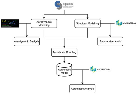
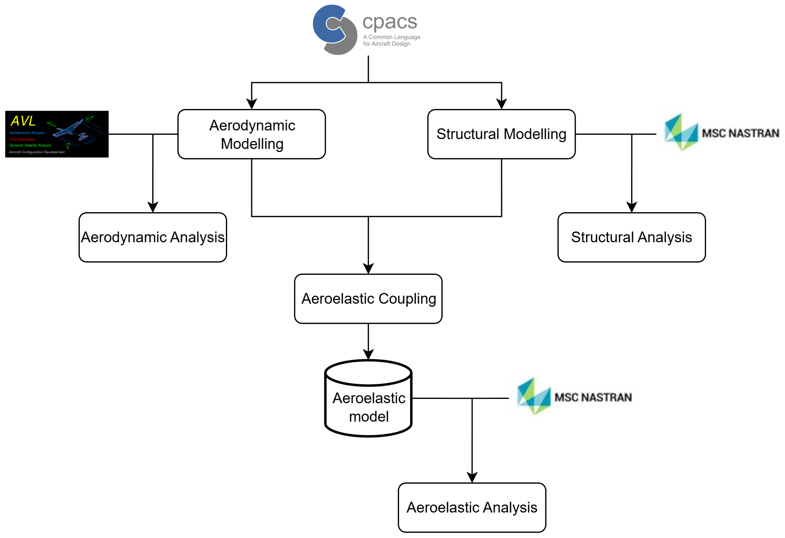
The specific architecture of FAST is illustrated in the flowchart in Figure 1. The FAST toolchain originates from a central CPACS dataset, which acts as the “single source of data” for the aircraft model. After parsing the information from CPACS, the process is divided into two primary branches: aerodynamic modeling and structural modeling (see Section 2.1 and Section 2.2, respectively). Once both models are established, FAST splines the aerodynamic and structural grids to map aerodynamic loads onto the structure and return structural deformations to the aerodynamic model. Section 2.4 details how the framework handles this aeroelastic coupling. FAST also generates auxiliary features to support diverse downstream analysis. Examples of these additional features are presented in Section 2.5.
Figure 1.
Computational workflow of the FAST toolchain.
2.1. Aerodynamics
FAST supports multiple aerodynamic analysis tools. AVL [14], a VLM [15] solver, is employed for rapid evaluation of rigid aircraft performance. Additionally, NASTRAN’s DLM is utilized for unsteady aerodynamic analysis.
A consistent geometric modeling principle is applied across all tools: the Outer Mold Line (OML) of each airframe component is extracted from CPACS, and the geometry is simplified to lifting plane. For the lifting surfaces, i.e., wings, and empennage, this simplification considers only the position of the leading edge and the local chord length, effectively neglecting the thickness of the OML in the aerodynamic mesh. This plane is then discretized into panels in both chordwise and spanwise directions. The fuselage is simplified into a cruciform model consisting of two perpendicular planes, where the top and side projected areas match the original fuselage geometry. Once the discretization is complete, the model is exported into a solver-compatible format.
Airfoil camber and geometric twist are handled according to the specific solver requirements. AVL directly processes airfoil coordinates to account for camber, while geometric twist is defined at each wing section. In NASTRAN, camber effects and geometric twist are incorporated using a correction matrix representing downwash vectors for each panel. Control surfaces in NASTRAN are modeled as separate aerodynamic panels, whereas AVL defines control surface hinge axes directly. Furthermore, the traditional limitation of NASTRAN neglecting drag is addressed; FAST incorporates induced drag computation using the Trefftz plane method [16].
2.2. Structural Modeling
FAST provides multi-fidelity structural solutions through either 1D beam or 2D shell modeling.
2.2.1. Beam Modeling
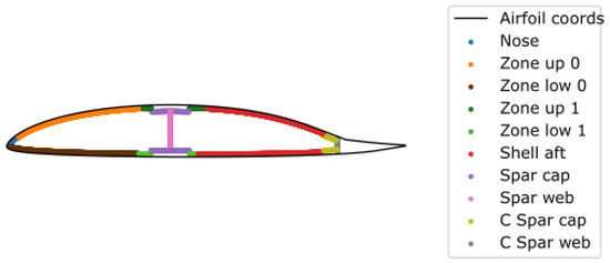
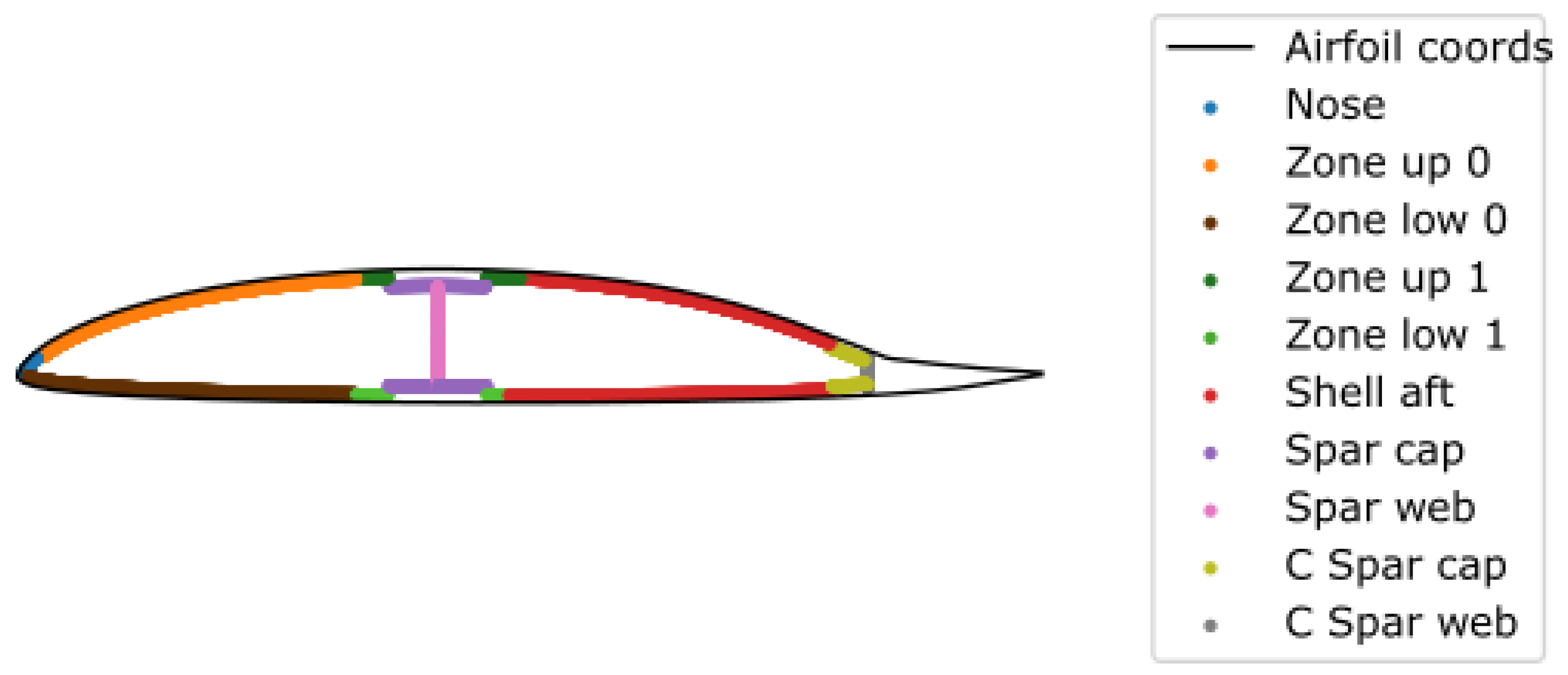
The beam model generation begins by parsing the CPACS file. This process extracts the geometric data required for the OML, along with parameters defining the structural components and shell laminate. Specifically, the airframe structural definition specifies the positioning and thickness of spar caps and webs. The wing shell is defined into chordwise zones. This zoning enables a refined laminate definition that captures local variations in layup and material properties. An exemplary arrangement of these zones is illustrated in Figure 2.
Figure 2.
Laminate zone definitions within the 2D cross-sectional profile.
Each zone is linked to a specific laminate definition file that details the ply stacking sequence, ply thicknesses, fiber orientation, and material properties. The laminate properties are computed for each zone using classical laminate theory [17]. Coupling effects in the spanwise direction are neglected in this approach.
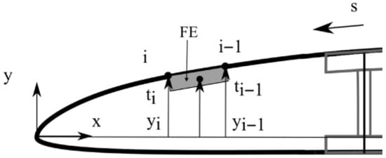
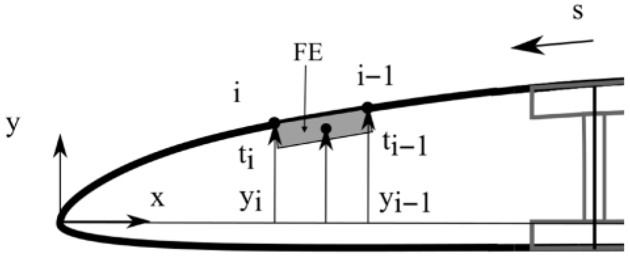
The resulting laminate properties are characterized by engineering constants—namely the in-plane elastic moduli (, ), the shear modulus (G), and the mass per unit area—following the methodology in [18]. To obtain global sectional properties, the thin-walled cross-sectional contour is discretized using Finite Elements (FE) (Figure 3). The total cross-sectional stiffness, mass, and inertia properties are then derived by numerically integrating the contributions of these elements across the entire profile.
Figure 3.
FE discretization of the cross-sectional profile.
To define the final beam properties, these sectional values are scaled or interpolated to account for geometric changes between consecutive spanwise sections. Table 1 summarizes the sectional properties used to define the beam’s elastic axis and structural characteristics.
Table 1.
Main strucutral parameters for the generation of the beam model.
The modeling methodology for control surface structures is analogous to that of the wing airframe. The wing profile is divided at the hinge line, after which the control surface profile is closed at its leading edge and normalized to a unit chord length. The parent wing’s geometric parameters—including dihedral, span, and sweep—are utilized to define the control surface OML. Furthermore, the same spanwise discretization is maintained to ensure consistency, and sectional properties are computed following the numerical integration procedure described above.
2.2.2. Shell Modeling
For high-fidelity shell modeling, a 3D geometric representation of the wing is required. The TIGL library (developed by DLR) is utilized to generate the fundamental OML of the wing and the internal structural topology, including the ribs and spars. Given that the wing box is the primary load-carrying component and the most relevant part for early-stage structural design, its geometry is precisely extracted. This is achieved by performing Boolean operations via the OpenCASCADE library, acting upon the union of the wing, rib, and spar geometries.
The Finite Element Model (FEM) generation of the wing box begins with a structured discretization process. Intersecting planes, defined in the chordwise and spanwise directions, are used to “cut” the wing box geometry via OpenCASCADE. This methodology ensures a high-quality, structured mesh. The ribs, spars, and skin are all represented using shell elements, while stiffeners and stringers are incorporated as beam elements at the intersecting locations. Various profile shapes for these reinforcing members—such as T, Z, or I-beam sections—can be defined. Since the link between the geometry and the material properties of each component is maintained within the CPACS schema, material properties are mapped directly from the configuration file onto the resulting FE mesh.
2.3. Mass Modeling
Mass modeling in FAST employs a hybrid approach, combining distributed material density with concentrated lumped masses. In the shell-based model, the structural mass is explicitly accounted for through the material density and geometric thickness of the airframe components, specifically the skin shells, spar webs, spar caps, ribs, and stringers. Conversely, in the beam-based model, structural masses and their corresponding inertia properties are derived from each 2D cross-section, as illustrated in Section 2.2. The resulting mass is modeled as a point mass at the CG of each segment.
Non-structural masses (e.g., engines, landing gear, systems, and avionics) are modeled as lumped masses with specific inertia properties. To simplify the FE connection, these lumped masses are assigned to the nearest existing FE node. Any resulting changes in the moment of inertia due to the CG shift are accounted for using the parallel axis theorem.
Fuel mass is determined based on the geometric volume. The fuel volume geometry is defined parametrically: the fuel tank volume is first defined by the rib bays. To accurately represent the usable fuel volume and its inertia, the specific fuel level and aircraft inclination are accounted for by creating an intersecting plane. This plane then cuts the 3D tank volume, yielding the precise geometry of the fuel volume. The fuel mass is placed at its CG and subsequently distributed across adjacent rib bay nodes.
FAST also supports customizable mass configurations by defining various payload–fuel ratios. To meet certification requirements, the aircraft’s CG positions for these cases can be tuned to cover the full range of operational CG shift. This tuning is achieved by allowing the user to select specific mass items (e.g., system mass in the fuselage) or defined portions of that mass (e.g., 4% of system mass) to serve as a tuning mass to achieve the desired CG location. This flexibility is essential for modeling novel concepts. For example, FAST supports hydrogen aircraft configurations by allowing for precise fuel mass relocation and the integration of specialized cryogenic tank masses.
In small aircraft, such as sailplanes or drones, the mass modeling of control surfaces requires specific considerations regarding mass balancing. Unlike larger aircraft, control surfaces in these categories are typically not actuated by high-stiffness hydraulic systems; instead, they are manually operated by the pilot. This results in significantly lower hinge-line stiffness. Furthermore, modeling this hinge-line stiffness involves high levels of uncertainty, as it must account for the cumulative effects of bearings, linkages, cable systems, and other mechanisms. These factors are further complicated by mechanical free-play. Free-play can drastically reduce the effective stiffness of the system, allowing oscillation amplitudes to increase rapidly without sufficient damping—even when the initial disturbance is small. Without careful mass balancing, this lack of stiffness can lead to undesirable mode coupling between the control surface and the primary structure, potentially triggering flutter. To handle this, FAST provides both manual and automatic approaches for control-surface mass balancing. By strategically placing balance masses, the control surface’s CG can be shifted forward. This process reduces the mass moment of inertia around the hinge line and minimizes the product of inertia unbalance. Ultimately, these adjustments decouple the critical vibration modes, ensuring aeroelastic stability.
2.4. Aeroelastic Coupling
The coupling of structural and aerodynamic models is achieved through several optional methodologies. One approach leverages NASTRAN’s native splining via a provisional transfer model. This model utilizes rigid elements (RBE2) to cover the entire wing area and interpolate aerodynamic loads from the aero panels. These rigid elements are connected to the load-carrying structure via interpolation constraint elements (RBE3), enabling the bidirectional transfer of loads and structural deformations between the aerodynamic and structural models. For beam-based models, the process is simplified by directly splining aero panels onto the beam grid points. This direct mapping eliminates the need for secondary RBE3 distribution elements, as loads and displacements are integrated directly at the beam nodes.
Alternatively, FAST supports loose coupling between the AVL aerodynamic model and the NASTRAN structural model using either rigid-body splining or radial basis function interpolation [19]. This loose coupling method is a key feature, as it enables the toolchain to be easily expanded in the future to incorporate higher-fidelity solvers, such as Computational Fluid Dynamics (CFD) for aerodynamics or non-linear solvers for structural analysis; see [20].
2.5. Ancillary Features
As the generated model serves different types of downstream analysis, several dedicated features are implemented in FAST to ease the interpretation of analysis results. To improve the visual representation of the geometry and/or the results, for instance, mode shapes during modal analysis, 1D dummy elements, known as PLOTEL elements in NASTRAN, are created at the leading and trailing edges.
Furthermore, detailed load analysis requires deriving the maximal forces and moments along the wing span to identify critical load cases and locations. For this purpose, load monitor stations are created at each rib position. At each rib location, a monitor point is defined, and all nodes outboard of that rib position are grouped as associated nodes. The integrated load monitoring feature then integrates loads about the rib position point over all associated nodes. Beyond structural loads, strip-wise aerodynamic normal force and pitching moment coefficients can also be monitored.
3. Applications and Capabilities Demonstration of FAST
The versatility of the FAST framework is demonstrated through three representative use cases, selected to encompass a wide array of structural layouts and operational categories. Specifically, the study evaluates a high-aspect-ratio UAV, a high-performance sailplane, and a commercial transport aircraft. These configurations represent a broad spectrum of aeronautical design, ranging from highly flexible research platforms to large-scale industrial transport aircraft.
3.1. Application I: UAV
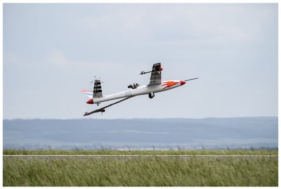
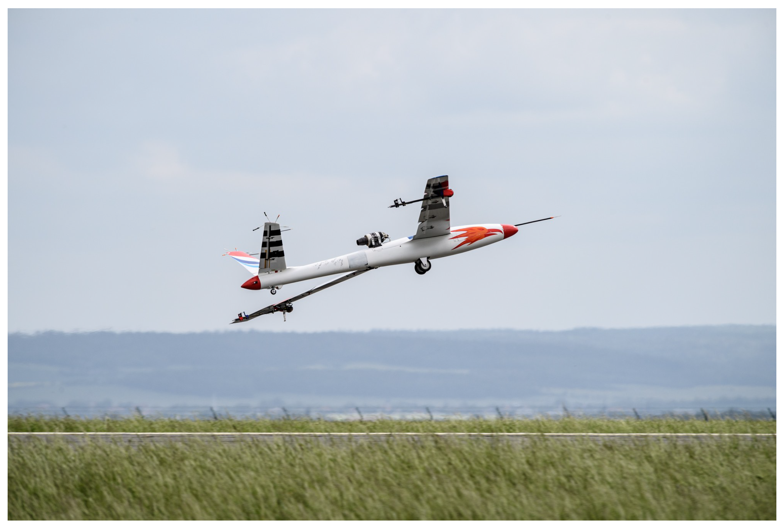
The P-FLEX (originally designated T-FLEX) is a fixed-wing, remotely piloted UAV developed within the framework of the EU project FLEXOP [21] and its successor, FLIPASED [22]. As the second iteration of the flight demonstrator, its primary objective is the in-flight validation of active flutter suppression technologies. As illustrated in Figure 4, the P-FLEX is powered by a jet turbine and features a wing with 7-m span, a 20-degree sweep-back angle, a high aspect ratio of 20, and a V-tail empennage. With a maximum takeoff weight of 65 kg, the vehicle serves as a sophisticated testbed for aeroelastic research. Key geometric parameters are summarized in Table 2, while a comprehensive description of the configuration is provided by Bartasevicius et al. [23].
Figure 4.
The P-FLEX demonstrator during takeoff.
Table 2.
Geometric specifications of the P-FLEX airframe components.
The demonstrator was specifically engineered to exhibit flutter at relatively low airspeed and frequency, ensuring that aeroelastic instabilities could be safely investigated within restricted airspace and controlled by onboard actuators. This was achieved through a specialized rod-and-mass assembly located at the wing tips. By positioning the movable mass at the aft end of the rod, the onset of flutter is intentionally triggered at lower speeds. Crucially, the assembly incorporates a safety mechanism that allows the pilot to rapidly shift the mass forward, thereby shifting the flutter boundary outside the flight envelope and restoring a stable configuration.
The P-FLEX configuration is particularly suited for validating the FAST toolchain for several reasons. First, its high-aspect-ratio, “super-flexible” wings are representative of future green aircraft designs, posing a significant challenge for dynamic aeroelastic modeling. Second, the platform is supported by a comprehensive dataset, including high-fidelity aeroelastic models that accurately reflect the manufactured wing properties. This is further bolstered by extensive experimental data, ranging from structural characterization via Ground Vibration Test (GVT) for FEM updating to real-time flight test data confirming the actual flutter speed. Consequently, the P-FLEX serves as an ideal high-fidelity benchmark to demonstrate the capabilities of the FAST framework and to verify its accuracy in predicting complex dynamic aeroelastic instabilities.
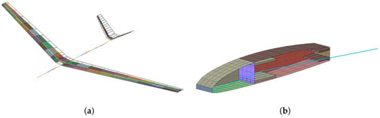
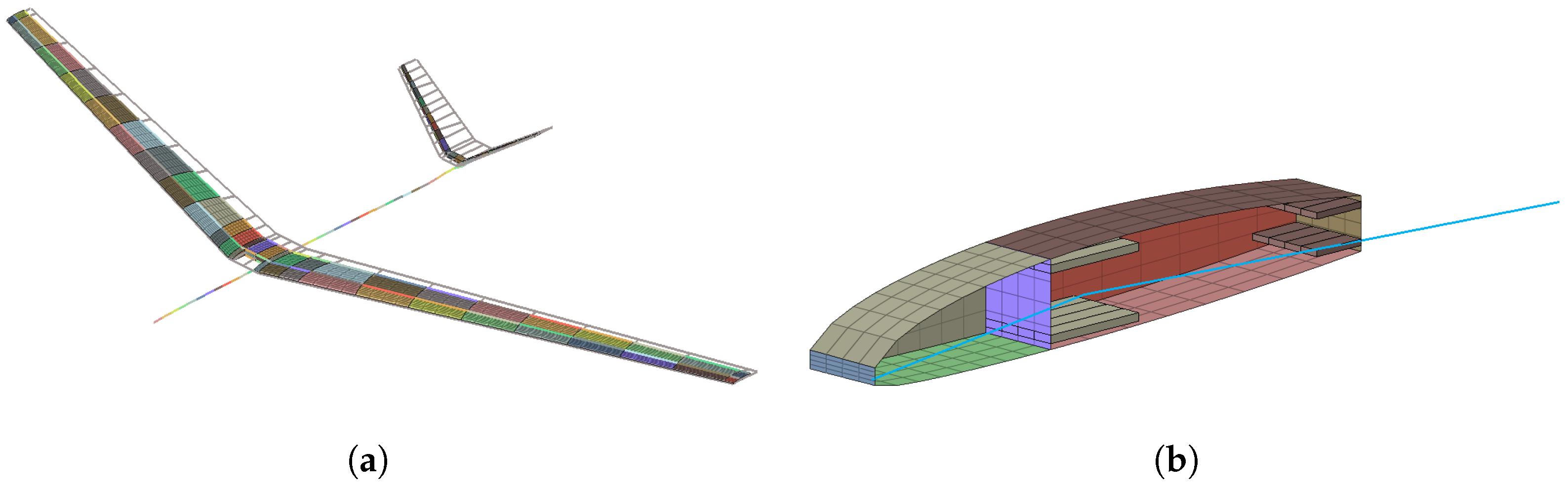
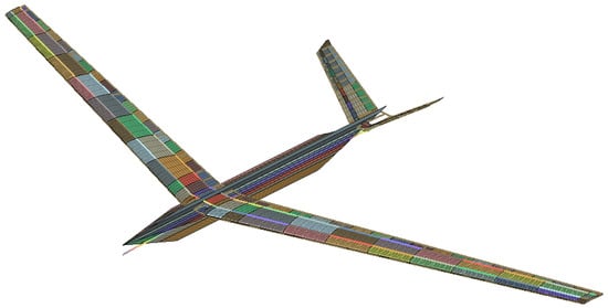
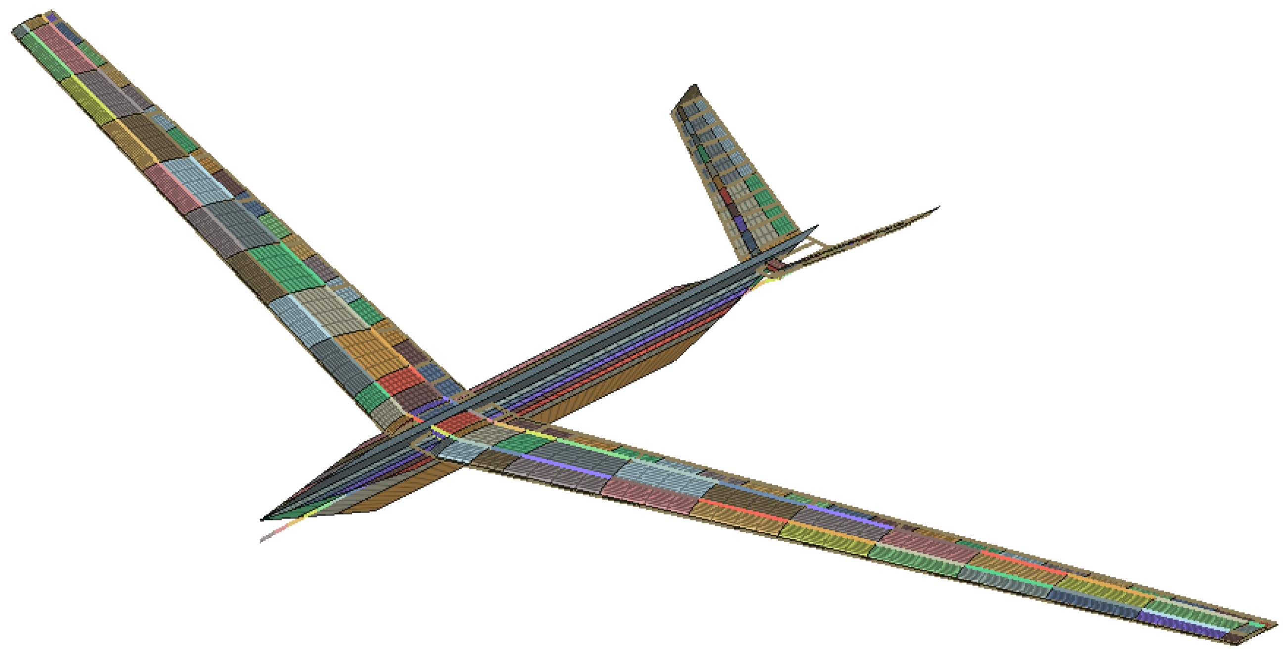
A shell-based FEM of the P-FLEX was generated using the FAST toolchain (Figure 5). To accurately represent the wing’s topology—characterized by a wingbox and a closed D-shape leading edge—two internal wingboxes were utilized to capture this specific geometry. The trailing edge components were excluded from the structural model, as they do not serve as primary load-carrying structures. The spar caps were modeled as beam elements with rectangular cross-sections. The complete structural arrangement is illustrated in the sectional view (Figure 5). Although FAST is not primarily intended for detailed design, complex features such as the flutter rod assembly were incorporated through equivalent lumped mass elements to precisely represent their mass distribution and inertial properties. The final integrated aeroelastic model is illustrated in Figure 6.
Figure 5.
P-FLEX structural model (components color-coded): (a) Isometric projection of the full-scale assembly. (b) Detailed view of a single spanwise segment (blue line indicates the splining rigid element).
Figure 6.
Aeroelastic model of the P-FLEX (components distinguished by color).
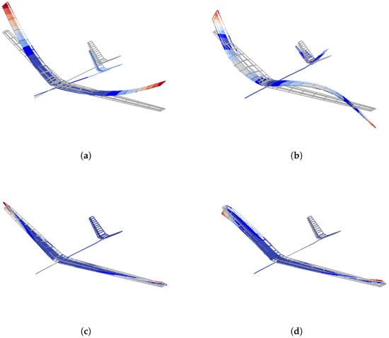
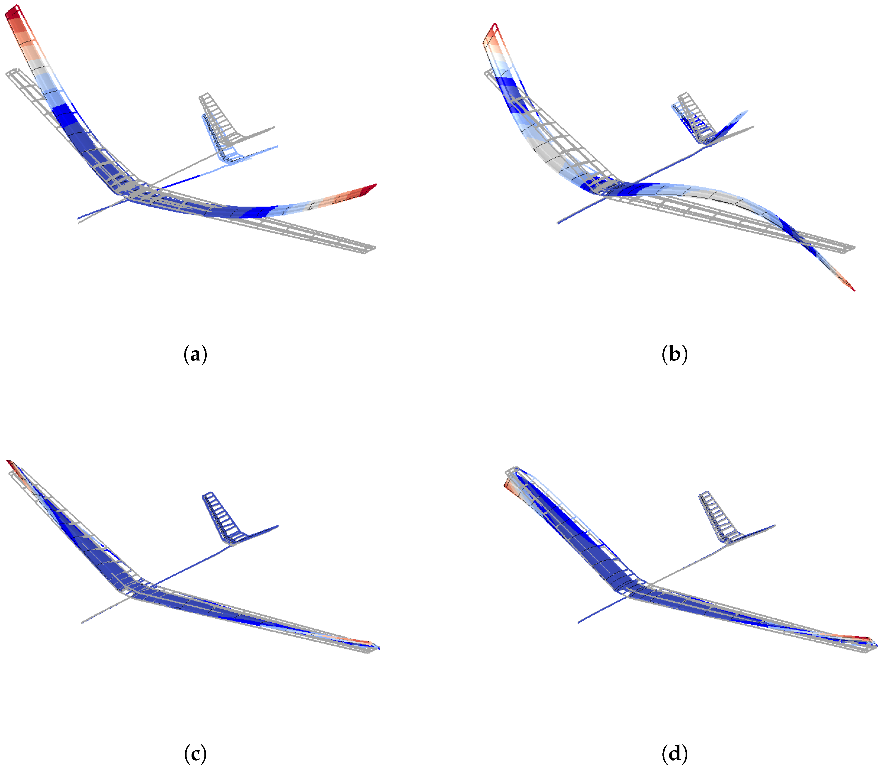
Prior to the flutter analysis, a modal analysis was conducted using MSC NASTRAN SOL 103 to validate the structural fidelity of the FAST-generated model against GVT data. This validation step is critical, as the accuracy of the subsequent flutter prediction is highly dependent on the initial modal representation. The analysis was performed under free-fly boundary conditions, with the resulting mode shapes depicted in Figure 7.
Figure 7.
Mode shapes of the P-FLEX: (a) 1st wing bending (symmetric); (b) 1st wing bending (anti-symmetric); (c) 1st wing torsion (symmetric); (d) 1st wing torsion (anti-symmetric). Color mapping indicates relative deformation magnitude (blue: min; red: max).
The GVT was conducted at the DLR Institute of Aeroelasticity in Göttingen, Germany. The aircraft was suspended from soft bungee cords to separate the elastic structural modes from the rigid body modes. The instrumentation comprised 150 IEPE accelerometers strategically distributed across the airframe and wings to capture high-accuracy modal data without mass-loading the structure. Structural excitation was provided by five 47N shakers positioned at the inner wings, outer wings, and fuselage, which delivered custom random and sine sweep signals. Data were acquired using Siemens SCADAS hardware, with subsequent modal identification using the PolyMAX software. Further information can be found in [24].
The comparison of modal frequencies between the numerical simulations and the GVT results is summarized in Table 3, while the modal mass comparison is presented in Table 4. Overall, the model achieves a good degree of accuracy. For the bending modes, the numerical model predicts higher frequencies and lower modal mass. This discrepancy is likely attributable to the composite transition zones in the manufactured P-FLEX, where the laminate thickness gradually decreases. Such manufacturing details were simplified in the FEM; specifically, these transition zones were omitted and represented by uniform, stiffer material properties, leading to higher global bending stiffness in the simulation.
Table 3.
Comparison of mode frequencies between simulation and GVT of P-FLEX.
Table 4.
Comparison of modal mass between simulation and GVT of P-FLEX.
Another contributing factor to the higher predicted bending frequencies is the assumption of a rigid fuselage and an ideally stiff wing–fuselage connection. In reality, the fuselage exhibits a degree of flexibility, and the physical connection is not ideally rigid as modeled in the simulation. This limitation could be addressed in the future by utilizing the beam-modeling capabilities of FAST to replace the rigid fuselage with a flexible representation.
The lower modal mass in the bending modes stems from the complex instrumentation within the UAV for measurement and actuation. Because the precise location of each component was not fully accounted for, the CG of the half-wing is more inboard in the model, with mass more concentrated toward the root. This explains the lower modal mass observed in the bending modes. Additionally, this lower modal mass contributes to the overestimation of the natural frequencies.
For the torsional modes, the modal mass shows a good correlation with less than 10% deviation; however, the predicted modal frequency is lower than the experimental results. This may be attributed to torsional stiffness deviations in the simulation model, which utilizes two wing boxes to mimic the real structure. This sectional simplification results in a smaller leading-edge cross-sectional area. Furthermore, the closed-box trailing edge at the root region was omitted in the simulation. As the toolchain is not intended for detailed design, such simplifications are acceptable within the scope of this research. Further manual refinements could be implemented to achieve a closer match if necessary.
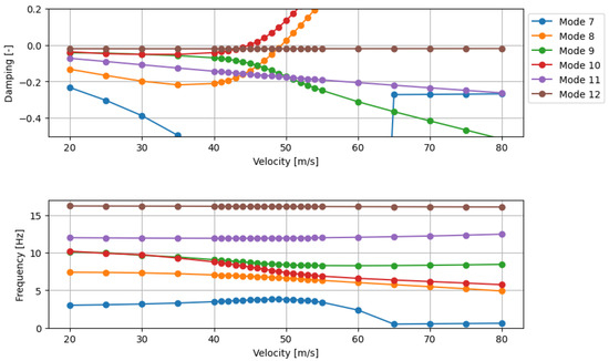
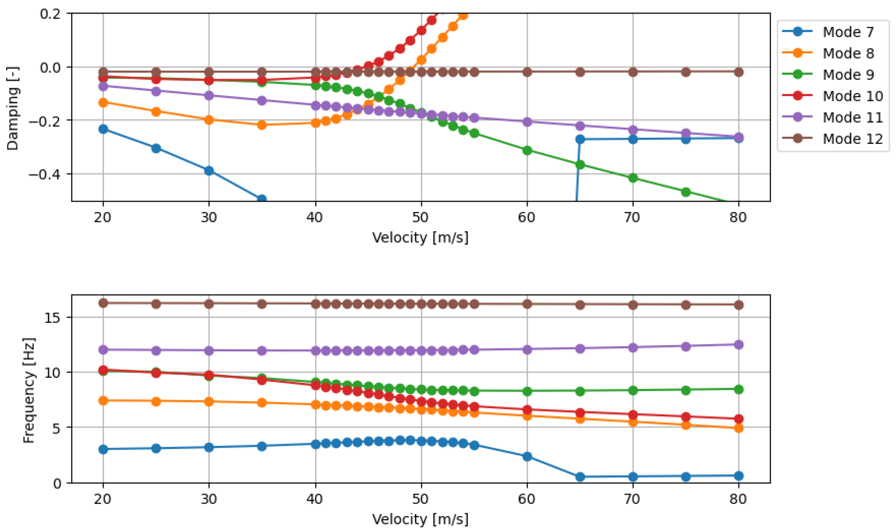
Aeroelastic stability was evaluated using the MSC NASTRAN SOL 145 (PK method) over a velocity range of 20 m/s to 80 m/s. The resulting velocity–damping (V–g) and velocity–frequency (V–f) plots (Figure 8) characterize a classical bending–torsion flutter mechanism. Specifically, the frequency of the anti-symmetric torsional mode (Mode 10) decreases with increasing airspeed until it couples with the bending mode (Mode 8).
Figure 8.
Velocity–damping (V–g) and velocity–frequency (V–f) plots for the P-FLEX flutter analysis.
The onset of flutter is predicted at approximately 45 m/s, defined as the point where the damping of the critical mode reaches zero. In comparison, the simulation-based prediction reported by Kier et al. [25] identified a flutter speed of 50 m/s. This deviation may be attributed to the fact that the model in [25] was updated using GVT data for mode frequencies and shapes. Furthermore, that study utilized an enhanced DLM incorporating body panels and in-plane aerodynamic forces, further corrected with CFD data to account for airfoil thickness and viscosity effects.
Despite these high-fidelity enhancements, the reported numerical values remain lower than the flutter speed of 55 m/s recorded during flight testing [25]. As noted in [25], numerical modal mass deviates from GVT results—a phenomenon also observed in the present study—which inherently leads to shifted flutter speed estimations. While the accurate prediction of flutter boundaries remains an active area of research due to the persistent gap between simulation and experimental results, the primary objective of this study is not to provide an exact flutter prediction. Instead, the focus is on enabling robust aeroelastic capabilities during the early design stage. Given the aforementioned structural model simplifications and the observed discrepancies in modal frequencies, the current level of predictive accuracy is deemed acceptable for the scope of this research.
3.2. Application II: Saiplane—Ventus 3T
A high-performance sailplane, the Ventus 3T, was selected as a further representative test case to demonstrate FAST’s capability in assessing structural dynamics using beam models. This configuration highlights FAST’s versatility in modeling structural concepts that deviate from the conventional multi-spar wingbox designs typical of commercial transport aircraft. Sailplane wings are characterized by a unique structural topology: a single primary spar, typically with an I- or box-shaped cross-section, carries approximately 90% of the bending loads [26]. The wing section is generally closed by a lighter C- or omega-shaped rear spar, while the fiber-reinforced skin provides the primary contribution to torsional stiffness [26].
The Ventus 3T wing consists of four trapezoidal segments with increasing dihedral and sweep. To enhance aerodynamic performance, each wing is equipped with four control surfaces (flaperons and ailerons). Table 5 summarizes the key specifications of the Ventus 3T.
Table 5.
Main parameters of the sailplane configuration.
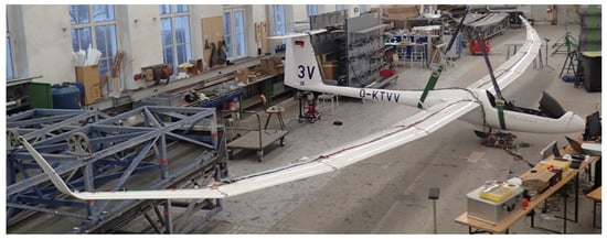
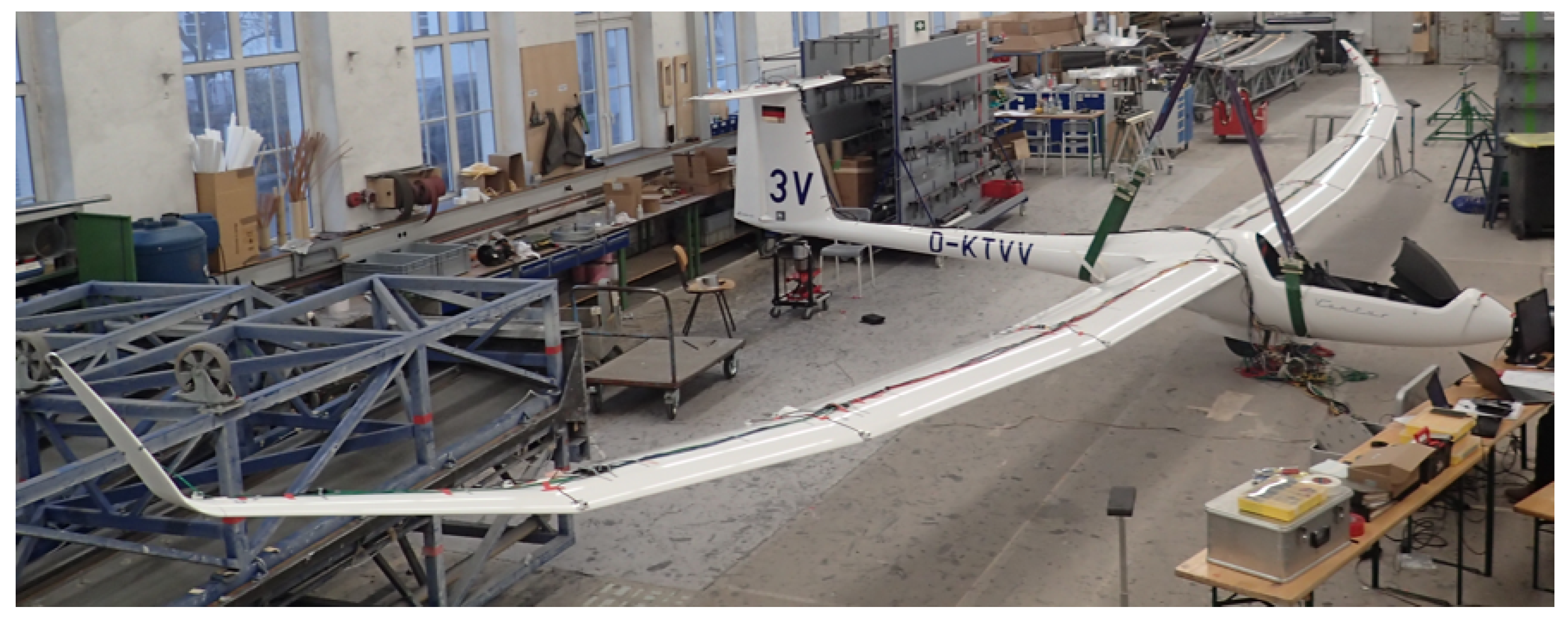
As a result of the LuFo-funded ProFla project—conducted in cooperation with Schempp-Hirth Flugzeugbau—this configuration serves as an ideal validation case. The project yielded a robust database of experimental results, including GVT data from Schempp-Hirth and modal characteristics and flutter behavior documented by the DLR Institute of Aeroelasticity [27]. These comprehensive datasets provide the high-fidelity benchmarks necessary for the validation of the FAST beam models. Figure 9 depicts the experimental setup of the GVT performed by Schmepp-Hirth.
Figure 9.
GVT setup for the Ventus 3 sailplane.
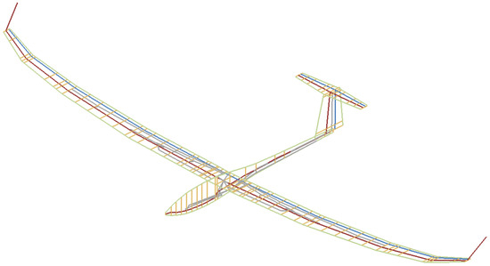
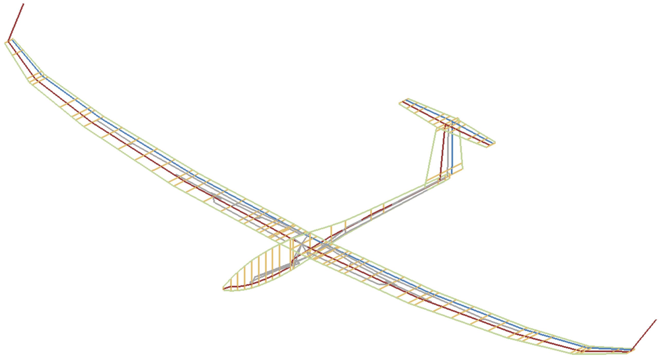
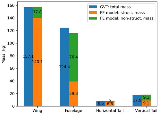
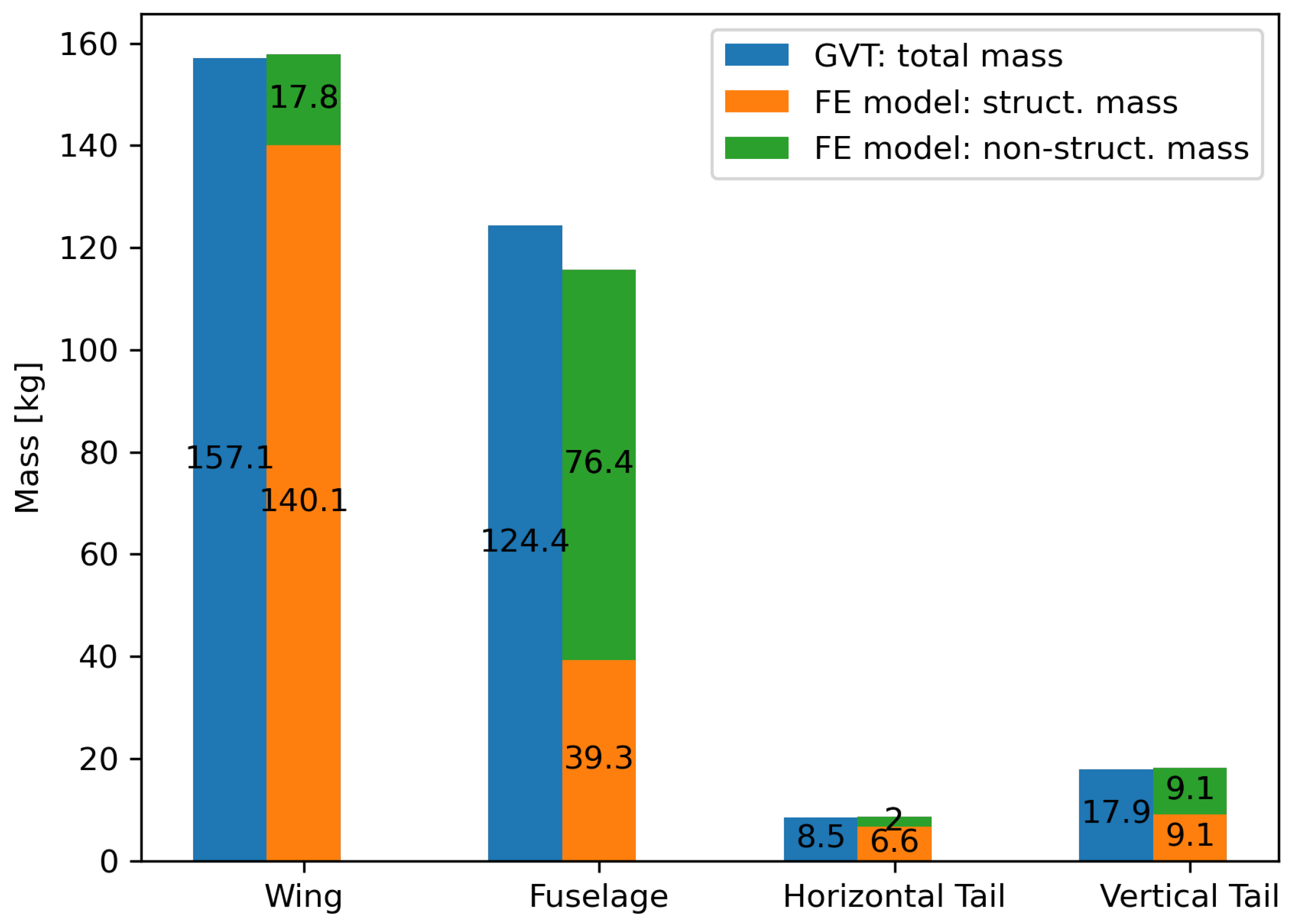
The FE beam model generated by FAST is illustrated in Figure 10, including the representation of mechanical control systems. Figure 11 compares the aircraft mass breakdown of the model with experimental reference data, encompassing both structural and non-structural contributions. For all components except the fuselage, the mass deviations remain well below 5%, falling within acceptable manufacturing tolerances for areal weight. The larger discrepancy observed in the fuselage is likely attributable to the high uncertainty associated with non-structural masses, which account for approximately 66% of the total fuselage mass (Figure 11). Overall, the FE model yields a total empty mass of 300.3 kg, compared to the 307.9 kg measured during GVT. This 2.5% deviation confirms the validity of the mass modeling approach implemented in FAST.
Figure 10.
Beam model of the Ventus 3T: mechanical controls (grey), visualization elements (green), hinge line (blue), structural components (red), and splining elements (yellow).
Figure 11.
Mass breakdown comparison: measured airframe components vs. FE model.
The validation of the Ventus 3 configuration is based on two independent GVT campaigns conducted by different institutions using distinct instrumentation. Identifying eigenmodes in these datasets involves significant complexity due to the high modal density and the inherent similarity between certain mode shapes, which necessitates careful engineering judgment. To ensure objectivity, the eigenfrequencies for both GVT campaigns, summarized in Table 6, were identified by selecting modes exhibiting the highest Phase Resonance Criterion (PRC) values. A PRC value approaching unity indicates a pure normal mode where the entire structure oscillates with a consistent phase lag relative to the excitation force, ensuring the extracted mode shape is minimally contaminated by neighboring modes.
Table 6.
Comparison of mode frequencies between simulation and GVTs of Ventus 3T sailplane.
As shown in Table 6, the identified frequencies differ between the two campaigns, with GVT2 generally exhibiting higher eigenfrequencies than GVT1. Notably, a modal swap was observed between the 2nd anti-symmetric wing bending (A2) and the 2-node fuselage bending (SR2) modes between the two experiments. Furthermore, generalized mass data was unavailable for GVT2. These experimental variations add complexity to the FE model validation, particularly regarding the selection of torsional modes.
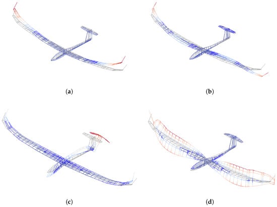
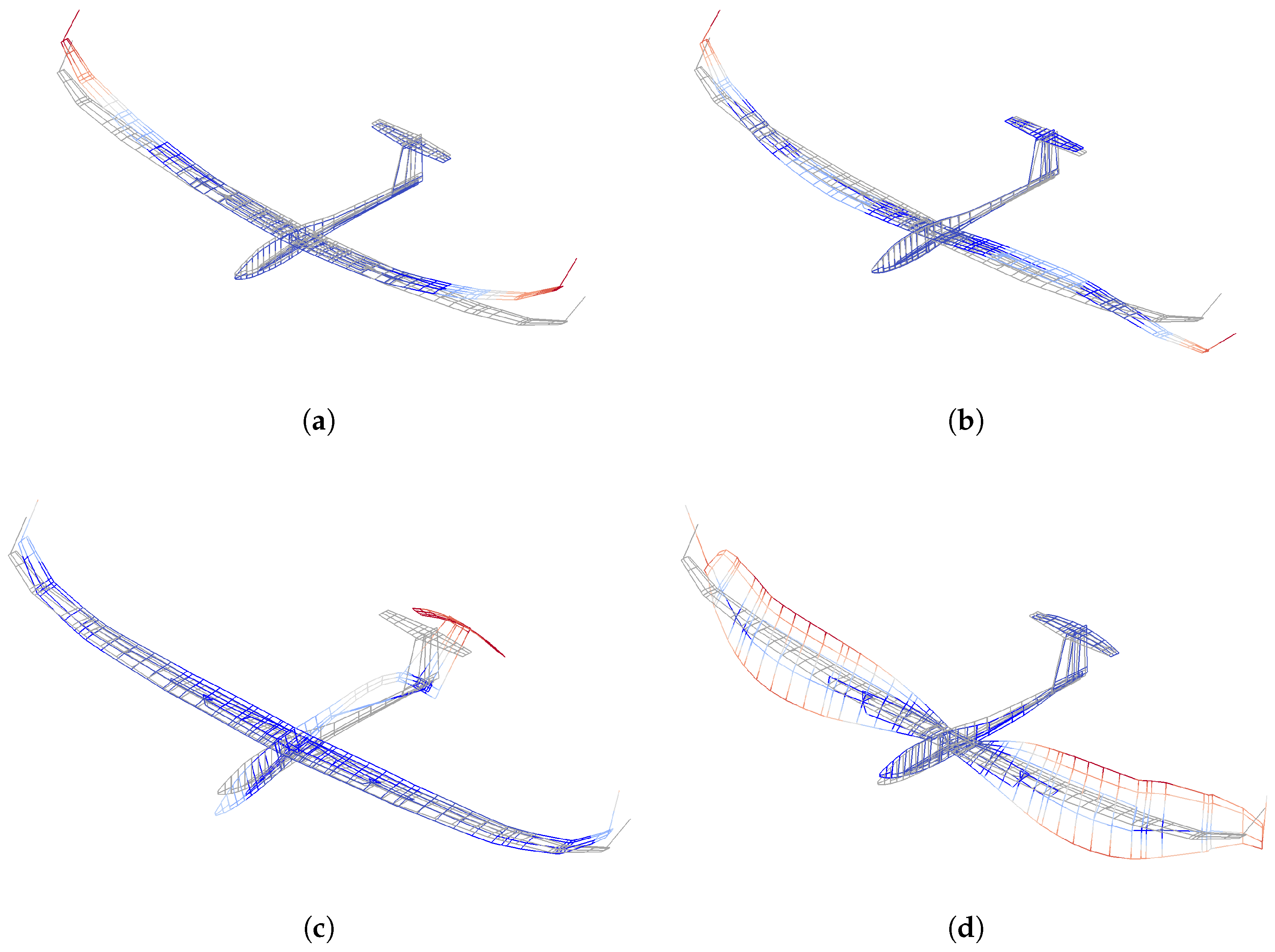
Overall, the FAST toolchain demonstrates good correlation with the experimental data, particularly with GVT2. Key exceptions include the 1st symmetric and 3rd anti-symmetric wing bending modes, which show significant variability between the two experimental tests. The model consistently overpredicts the 2nd anti-symmetric wing bending frequency, likely due to uncertainties in the fuselage mass distribution and moments of inertia, as these modes involve significant fuselage participation. Furthermore, discrepancies in the in-plane mode frequency likely stem from modeling uncertainties in the wing–wing and wing–fuselage connections. Nevertheless, the deviation in torsional mode frequencies remains below 6%. The representative mode shapes from simulation are shown in Figure 12.
Figure 12.
Mode shapes of the Ventus 3T: (a) 1st wing bending (symmetric); (b) 1st wing bending (anti-symmetric); (c) 2 nodes fuselage bending; (d) 1st wing torsion (symmetric). Color mapping indicates relative deformation magnitude (blue: min; red: max).
Table 7 presents a comparison of the generalized masses between the FE simulation and the GVT1 dataset, as generalized mass data for GVT2 was unavailable. The comparison is restricted to the specific modes identified during that test. The results indicate that the FE model overpredicts the generalized mass for the first and third symmetric bending modes. For all other identified modes, the numerical model tends to underpredict the generalized mass.
Table 7.
Comparison of modal mass between simulation and GVT of Ventus 3T.
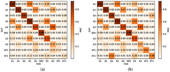
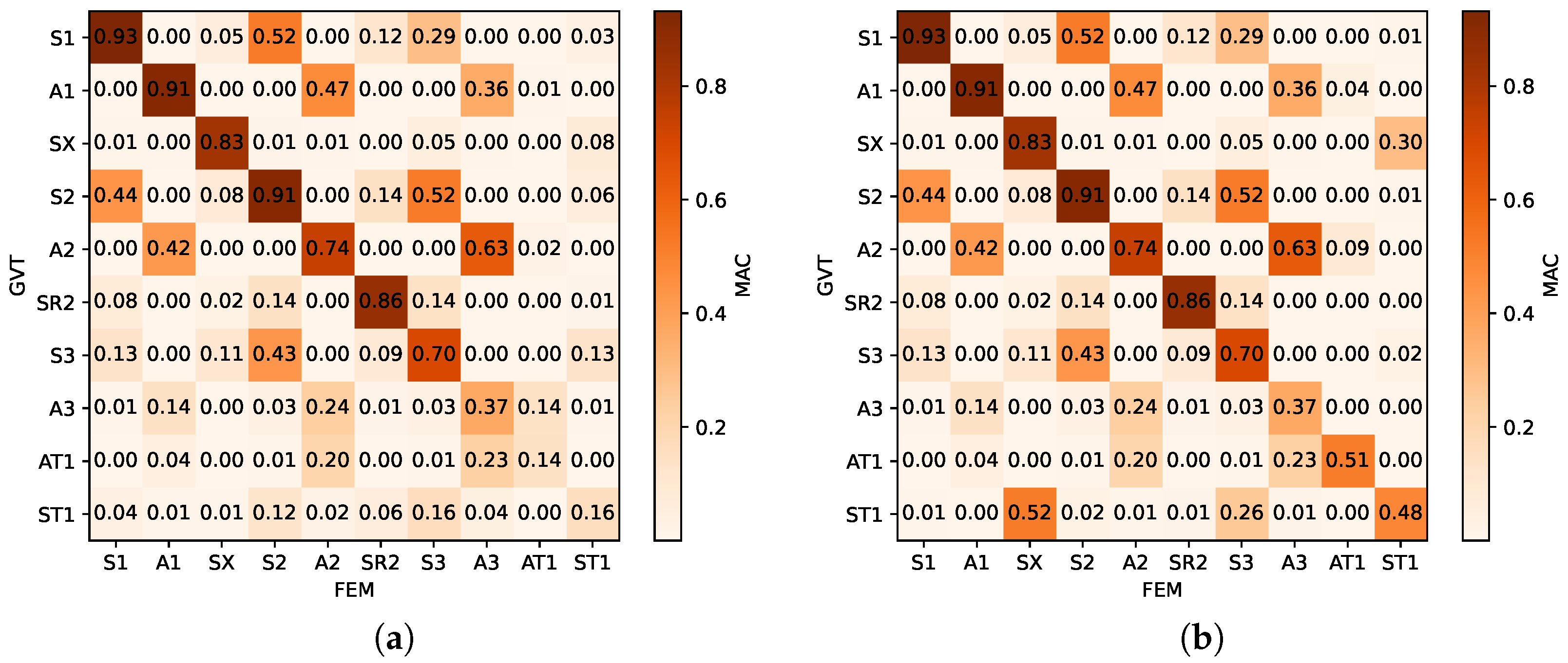
The Modal Assurance Criterion (MAC) was used to quantify the correlation between mode shapes and assess the causes of the observed deviations. The MAC matrices in Figure 13a represent the results obtained from GVT2. High diagonal MAC values are observed up to the 3rd symmetric wing bending mode. This strong correlation, combined with small frequency deviations, demonstrates that FAST accurately represents the structural–dynamical behavior of high-aspect-ratio composite aircraft in the low-to-mid frequency regime (up to ≈ 15 Hz).
Figure 13.
MAC matrices for the Ventus 3T: (a) PRC-based modal identification; (b) alternative selection of eigenmodes targeting improved winglet kinematics.
However, the torsion modes exhibit poor correlation (MAC < 0.20), primarily due to significant deviations in the eigenvectors at the wing–winglet interface, specifically between the winglet tip and the outermost wing station. In the GVT data for the ST1 mode, the winglet tip sensor displays a substantial x-direction displacement oriented opposite to the motion of the neighboring wing station. Conversely, the FE model predicts a negligible x-component at the winglet tip. This phase and magnitude mismatch in the local eigenvectors is the primary driver of the reduced MAC values. A similar directional mismatch (phase opposition) is observed for the AT1 mode.
These variations add a layer of complexity to mode selection. Due to the slender wing construction and small chord length, the chordwise distance between sensors is minimal, resulting in relatively small eigenvector magnitudes compared to those at the winglet tips. However, relying solely on winglet tip eigenvectors can be misleading. For instance, ST1 mode shapes are recognizable in both GVT and FEM at multiple frequencies ( Hz; Hz). A similar behavior occurs for the first anti-symmetric torsion (AT1), where FEM candidates were identified at Hz and Hz.
While the correlation for the torsion modes could be improved by selecting FEM modes that more closely match the GVT’s relative wing–winglet kinematics (see Figure 13b), such an approach introduces a new set of compromises. Specifically, choosing these “kinematically similar” modes leads to either a significant reduction in the PRC for the GVT data or a substantial increase in the frequency deviation between the numerical and experimental results. For the AT1 mode, selecting Hz improves the kinematic replication but increases the frequency deviation to approximately 25%. Similarly, evaluating the ST1 mode at Hz and Hz yields a low frequency deviation of only , yet this comes at the cost of modal purity; the PRC for the experimental data drops from to , indicating that the mode is less isolated and potentially influenced by neighboring structural dynamics.
The divergent winglet behavior is likely attributable to modeling uncertainties within the wing–winglet interface. An idealized representation of the structural connection may fail to capture the observed kinematics. Furthermore, discrepancies in the local mass distribution or inertial properties—such as a mismatch in the winglet’s CG—could alter the coupling between torsion and longitudinal motion, leading to the poor correlations observed in the MAC matrices.
While a model update could further improve these results, the agreement between the non-updated beam model and the experimental data is considered satisfactory for the scope of this study, specially at lower frequencies.
3.3. Application III: Transport Aircraft
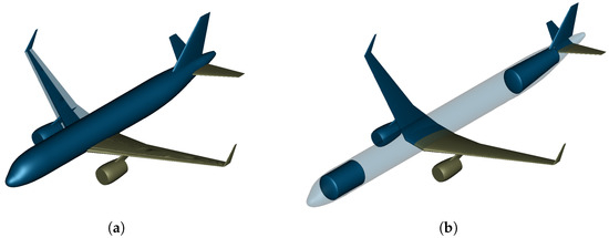
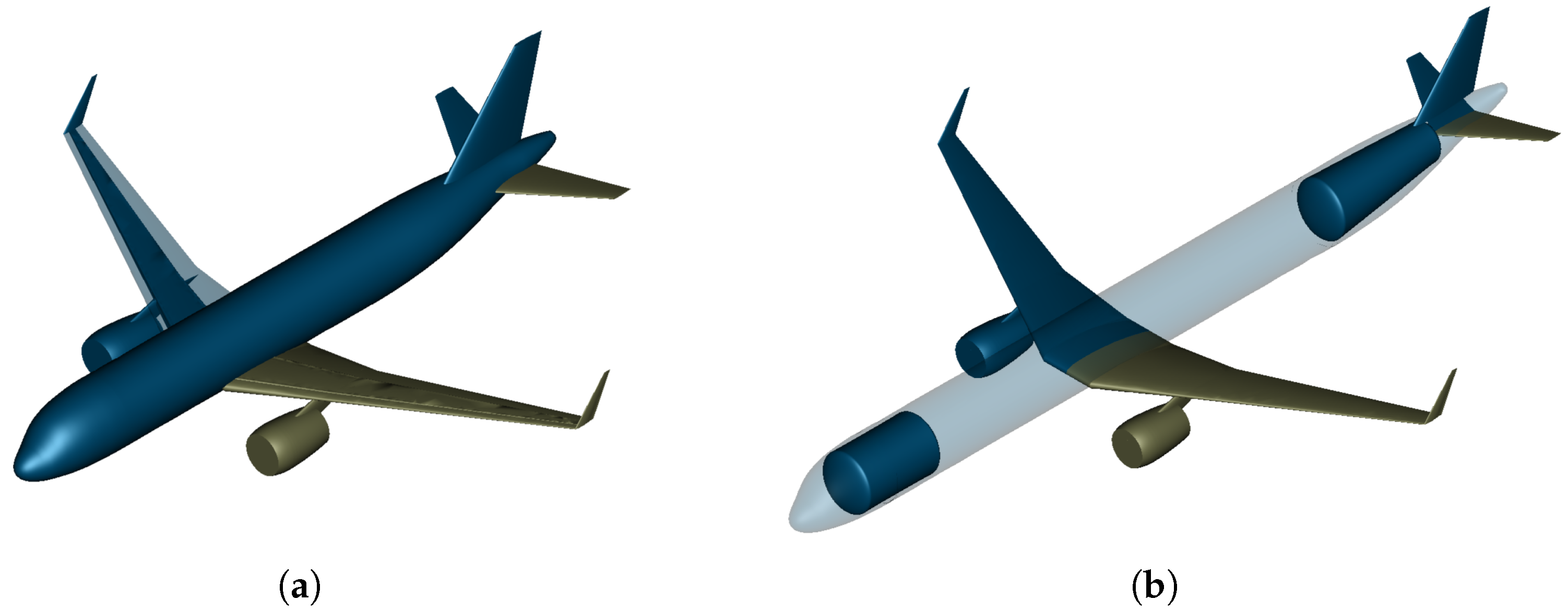
To demonstrate the tool’s capability in modeling large-scale transport aircraft, an A320-like reference configuration developed by Bauhaus Luftfahrt (BHL) is employed. This configuration, featuring a winglet and utilizing aluminum as the primary material, was designed using the Bauhaus Luftfahrt Aircraft Design Environment (BLADE), and adheres to the same top-level requirements as the A320. Key specifications are detailed in Table 8, and the full geometry is illustrated in Figure 14.
Table 8.
Main specifications of the A320-like reference aircraft.
Figure 14.
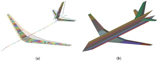
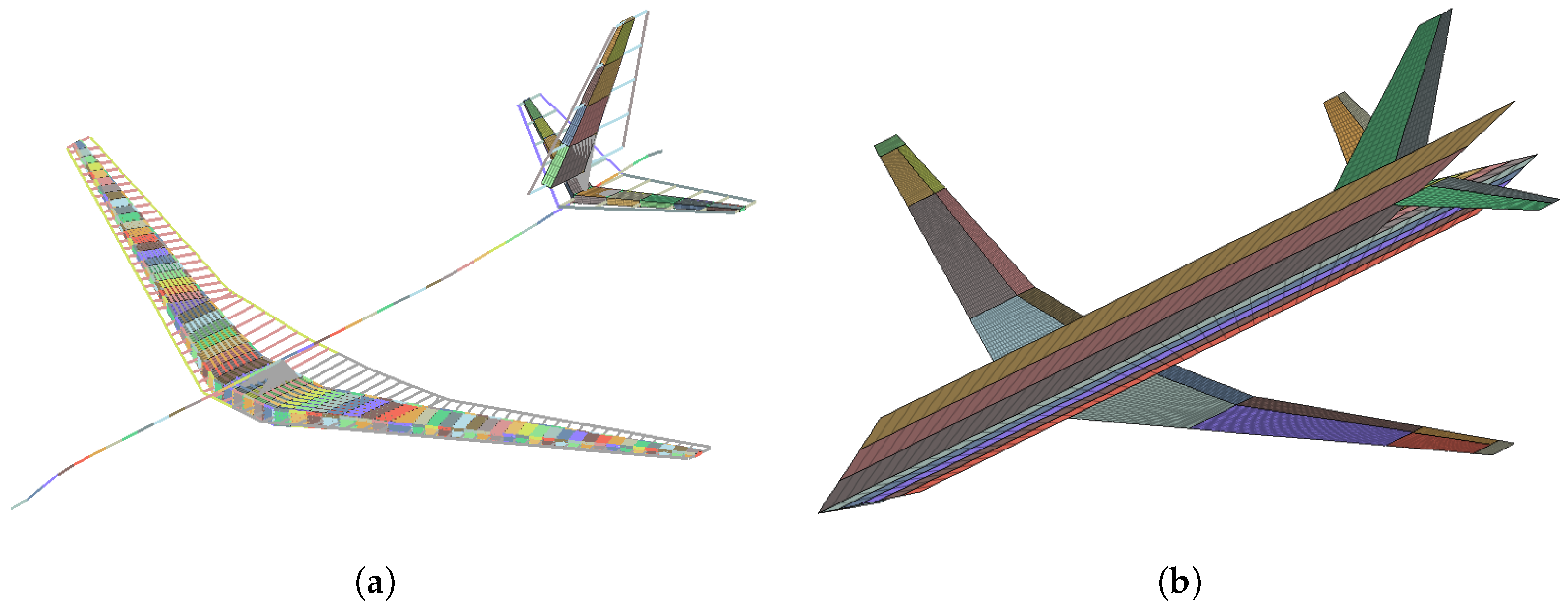
Geometry of aircraft configurations, with mirrored components indicated by olive color: (a) Kerosene-fueled reference; (b) Hydrogen-powered derivative.
As a response to the aviation industry’s decarbonization efforts, a hydrogen-powered derivative—designed under the same requirements and also derived via BLADE—is analyzed to showcase the toolchain’s applicability to novel green aircraft concepts. The hydrogen aircraft utilizes two independent tanks (one forward and one aft) to minimize CG shifts during operation, thereby reducing trim drag, as illustrated in Figure 14.
The resulting aeroelastic model, generated using the FAST, is visualized in Altair HyperMesh as shown in Figure 15. Structurally, the wing box is meshed with shell elements, while stringers and stiffeners are represented by beam elements. Given that the analysis focuses primarily on the wing, the fuselage is modeled using rigid beams. Aerodynamically, the wing and control surfaces are explicitly modeled, while the fuselage is represented by a cruciform arrangement.
Figure 15.
Aeroelastic model (components distinguished by color and rendered in HyperMesh): (a) Structural mesh; (b) Aerodynamic mesh.
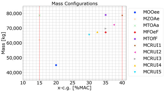
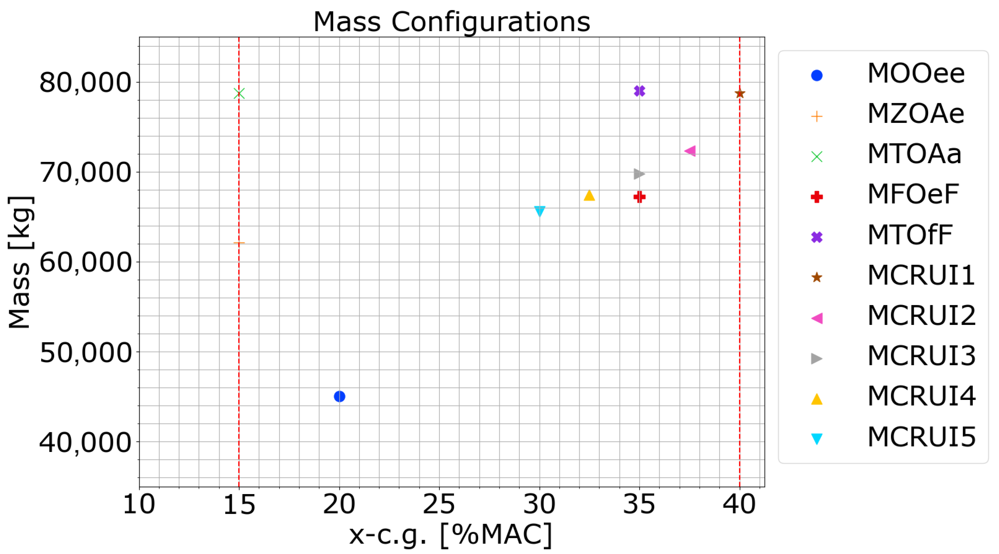
To demonstrate the tool’s flexibility, various mass configurations were generated. Table 9 presents a selection of these configurations—defined by specific payload and fuel ratios—along with their corresponding CG positions; note that certain cruise mass configurations (MCRUI) have been omitted for brevity. The resulting CG plot (Figure 16) covers an operational range from 15% to 40% of the Mean Aerodynamic Chord (MAC). This range is essential for load analysis, a fundamental step in aircraft design used to quantify structural loads for subsequent component sizing.
Table 9.
Representative mass configurations with payload-fuel ratios and corresponding CG positions.
Figure 16.
CG positions for various mass configurations relative to operational limits.
The aeroelastic model is utilized to perform analyses covering load cases defined in Certification Specification (CS)-25. While the scope here is limited to a capability demonstration rather than a comprehensive industry-level loads analysis campaign, only steady maneuver loads are simulated for a representative mass configuration. The load cases include pull-up, push-over, and roll maneuvers. Speeds and altitudes were selected in accordance with CS-25 requirements [28], spanning from sea level to the maximum operational flight level. In total, 60 maneuver load cases were simulated; an overview of these cases is provided in Table 10.
Table 10.
Flight conditions for the simulated maneuver load cases.
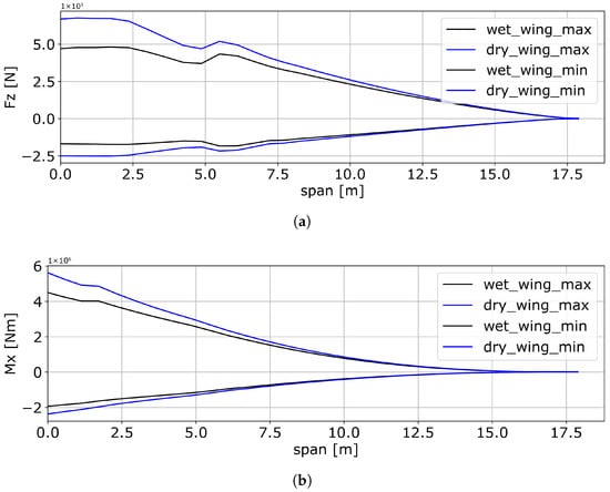
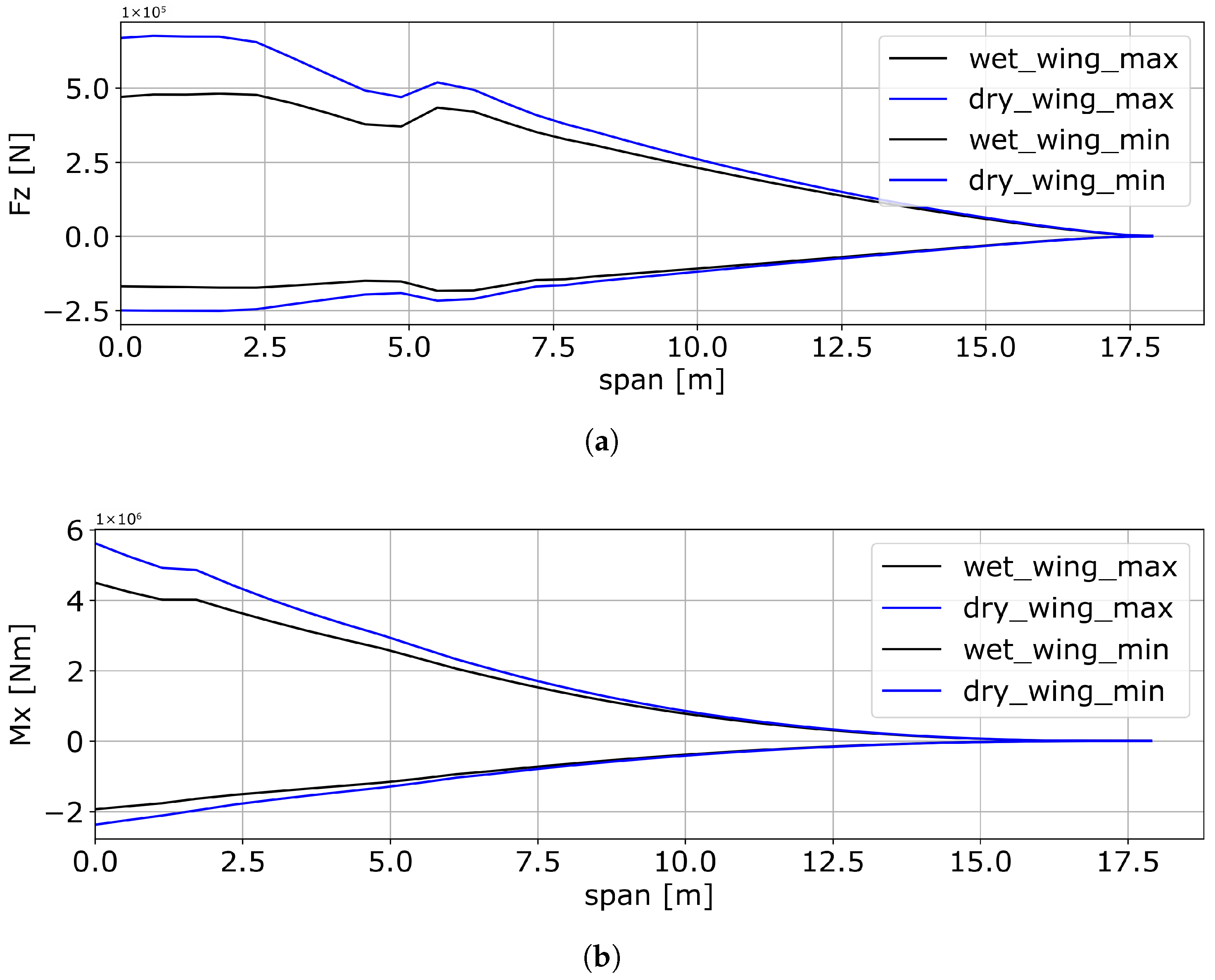
Load analysis results were post-processed at the monitoring stations described in Section 2.5. A 1D load envelope detailing the critical shear force, bending moment, and torsional moment was derived and is presented in Figure 17. The discontinuity in the shear force at approximately 5 m spanwise is a physical representation of the engine and pylon integration. The observed trends are qualitatively verified with literature [29,30], which details the structural loads of different aircraft configurations. To ensure a consistent comparison from a structural sizing perspective, both configurations were evaluated at an identical MTOM. Comparing the envelopes reveals a significant increase in internal loads for the ‘dry’ hydrogen wing: specifically, a 48% increase in shear force () and a 25% increase in bending moment (). This increment is directly attributable to the absence of wing-borne fuel mass in the hydrogen configuration, which eliminates the inertia relief effect. In this ‘worst-case’ scenario, the hydrogen is stored in the fuselage, leaving the wing internal volume empty while the total aircraft weight remains at MTOM. Consequently, the wing must support the full aerodynamic lift without the relief of distributed fuel weight. While a comparison against the reference mass case MZOAe (zero fuel mass) would yield different deltas, the MTOM-based comparison is prioritized here as it represents the critical design point for structural sizing.
Figure 17.
Comparison of loads. (a) shear force. (b) bending moment.
4. Conclusions
This paper presents the methodology and applications of the FAST, a multi-fidelity aeroelastic modeling environment designed to support aircraft design at various stages of development. The capabilities of FAST were demonstrated through three distinct aircraft configurations, ranging from small UAVs to large transport aircraft.
The analysis of the P-FLEX UAV and the Ventus sailplane—both characterized by HAR flexible wings—highlighted FAST’s proficiency in capturing the complex aeroelastic behavior inherent in modern wing designs. The modal and flutter analysis results indicate that the models generated by FAST accurately represent the aircraft’s aeroelastic characteristics. Such physics-based modeling proves invaluable in the early design phase, providing a robust foundation for decision-making where traditional empirical data may be insufficient.
Furthermore, the static aeroelastic analysis of an A320-like transport aircraft and its “dry-wing” derivative demonstrated the toolbox’s capacity to predict wing loads in large-scale flexible airframes. This application particularly highlighted FAST’s adaptability for investigating disruptive technologies, such as hydrogen-powered aircraft. In scenarios where historical design data is missing, the ability to rapidly generate physics-based aeroelastic models is essential for assessing the structural implications of alternative fuel integrations.
From a configuration perspective, FAST is designed for tube-and-wing architectures featuring various empennage layouts, including conventional, T-tail, and V-tail geometries. The toolchain’s multi-fidelity structural capabilities allow it to adapt to the specific needs of the design cycle. Within the conceptual design stage, the beam modeling features of FAST are particularly suitable, as their high computational efficiency allows for the rapid exploration of large design spaces. As the design matures, the shell modeling features become more appropriate for high-fidelity structural verification and detailed stress analysis. Ultimately, FAST serves as an ideal tool for designers who require a seamless transition between design cycles. It is especially valuable for the development of non-conventional airframes—such as those utilizing hydrogen propulsion—where traditional empirical scaling laws and historical data are no longer applicable.
Overall, the automated workflows within FAST enable the rapid generation of high-fidelity structural and aerodynamic models. This significantly enhances efficiency in the aeroelastic analysis process while maintaining the versatility required to handle diverse aircraft types and fidelity requirements. By providing a bridge between rapid conceptualization and rigorous structural verification, the FAST toolchain empowers engineers to explore the aeroelastic boundaries of sustainable aviation technologies with greater confidence—driven by physics-based modeling—and reduced lead times achieved through high-level automation.
5. Outlook
Despite its contributions to bridging the research gap in aeroelastic toolchains, several limitations remain. Currently, FAST focuses primarily on wing modeling with the fuselage represented by a beam. While this simplification is valid for investigating the aeroelastic characteristics of HAR wings—the primary focus of current study—future assessments of hydrogen tank integration will necessitate more sophisticated fuselage modeling capabilities. Furthermore, the current shell modeling approach for wings utilizes additional internal wingboxes to approximate leading and trailing edge topologies. Although this is a justifiable simplification for large transport aircraft, where the central wingbox serves as the primary load-carrying structure, the structural deviations of these secondary elements may become significant for smaller UAVs and should be addressed in future iterations.
Additionally, while the UAV case was verified using flight test data, the validation for the Ventus sailplane was limited to structural modal data. Future efforts should aim for a more comprehensive verification of the aeroelastic behavior—for instance, through wind tunnel testing or dedicated flight campaigns—to further mature the toolchain.
Future work will focus on expanding the features of FAST to include more complex structural architectures. The toolbox will be further tested with disruptive configurations, such as truss-braced wings, blended wing bodies, and tandem wing designs. Ultimately, efforts will be made to fully integrate FAST into aircraft design environments, facilitating physics-based design decisions throughout the entire aircraft development lifecycle.
Author Contributions
Conceptualization, F.Y. and C.S.S.; methodology, F.Y. and C.S.S.; software, F.Y. and C.S.S.; validation, F.Y. and C.S.S.; formal analysis, F.Y. and C.S.S.; investigation, F.Y. and C.S.S.; resources, F.Y. and C.S.S.; data curation, F.Y. and C.S.S.; writing—original draft preparation, F.Y. and C.S.S.; writing—review and editing, M.H.; visualization, F.Y. and C.S.S.; supervision, M.H.; project administration, M.H.; funding acquisition, M.H. All authors have read and agreed to the published version of the manuscript.
Funding
This research was funded by the Federal Ministry for Economic Affairs and Climate Action of Germany, grant number 20M2247D. The APC was funded by Technical University of Munich.
Data Availability Statement
The datasets presented in this article are not readily available because the data for the Ventus sailplane is the property of Schempp-Hirth Flugzeugbau. Requests to access the datasets should be directed to Schempp-Hirth Flugzeugbau.
Acknowledgments
The authors thank the EU Horizon 2020 projects FLEXOP (Grant Agreement No. 636307) and FLIPASED (Grant Agreement No. 815058), as well as the German LuFo project ProFla (Grant No. 20Q1952C), as the data utilized in this study were collected during these research initiatives. The authors also thank Alexandros Lessis from Bauhaus Luftfahrt for his valuable support in providing the CPACS data for the transport aircraft configuration. Furthermore, the authors are grateful to Fabian Sturm for his insightful discussions and contributions.
Conflicts of Interest
The authors declare no conflicts of interest. The funders had no role in the design of the study; in the collection, analyses, or interpretation of data; in the writing of the manuscript; or in the decision to publish the results.
Abbreviations
The following abbreviations are used in this manuscript:
| BHL | Bauhaus Luftfahrt |
| BLADE | Bauhaus Luftfahrt Aircraft Design Environment |
| CFD | Computational Fluid Dynamics |
| CG | Center of Gravity |
| CPACS | Common Parametric Aircraft Configuration Schema |
| CS | Certification Specification |
| DLM | Doublet Lattice Method |
| DLR | Deutsche Forschungsanstalt für Luft- und Raumfahrt |
| XML | Extensible Markup Language |
| FAST | Flexible Aero-Structural Toolbox |
| FE | Finite Element |
| FEM | Finite Element Model |
| FLEXOP | Flutter Free FLight Envelope eXpansion for ecOnomical Performance improvement |
| FliPASED | Flight Phase Adaptive Aero-Servo-Elastic Aircraft Design Methods |
| HAR | High Aspect Ratio |
| GVT | Ground Vibration Test |
| MAC | Mean Aerodynamic Chord |
| MAC | Modal Assurance Criterion |
| MDO | Multidisciplinary Design Optimization |
| MTOM | Maximum Take-Off Mass |
| MZFM | Maximum Zero-Fuel Mass |
| NA | Neutral Axis |
| NeoCASS | Next generation Conceptual Aero-Structural Sizing Suite |
| OML | Outer Mold Line |
| OEM | Operating Empty Mass |
| PRC | Phase Resonance Criterion |
| SC | Shear Center |
| SHARPy | Simulation of High Aspect Ratio aeroplanes in Python |
| UAV | Unmanned Aerial Vehicle |
| UM/NAST | University of Michigan’s Nonlinear Aeroelastic Simulation Toolbox |
| VLM | Vortex Lattice Method |
References
- Lee, D.; Fahey, D.; Skowron, A.; Allen, M.; Burkhardt, U.; Chen, Q.; Doherty, S.; Freeman, S.; Forster, P.; Fuglestvedt, J.; et al. The Contribution of Global Aviation to Anthropogenic Climate Forcing for 2000 to 2018. Atmos. Environ. 2021, 244, 117834. [Google Scholar] [CrossRef] [Scilit] [PubMed]
- Drela, M. Flight Vehicle Aerodynamics; MIT Press: Cambridge, MA, USA, 2014. [Google Scholar]
- Del Carre, A.; Muñoz-Simón, A.; Goizueta, N.; Palacios, R. SHARPy: A Dynamic Aeroelastic Simulation Toolbox for Very Flexible Aircraft and Wind Turbines. J. Open Source Softw. 2019, 4, 1885. [Google Scholar] [CrossRef] [Scilit]
- Su, W.; Cesnik, C.E. Strain-Based Geometrically Nonlinear Beam Formulation for Modeling Very Flexible Aircraft. Int. J. Solids Struct. 2011, 48, 2349–2360. [Google Scholar] [CrossRef] [Scilit]
- Drela, M. ASWING, version 6.02; MIT Press: Cambridge, MA, USA, 2016.
- Jasa, J.P.; Hwang, J.T.; Martins, J.R.R.A. Open-Source Coupled Aerostructural Optimization Using Python. Struct. Multidisc. Optim. 2018, 57, 1815–1827. [Google Scholar] [CrossRef] [Scilit]
- Voß, A. Loads Kernel User Guide; Technical Report; Institut für Aeroelastik, Deutsches Zentrum für Luft- und Raumfahrt: Göttingen, Germany, 2020. [Google Scholar]
- Gray, J.S.; Hwang, J.T.; Martins, J.R.R.A.; Moore, K.T.; Naylor, B.A. OpenMDAO: An Open-Source Framework for Multidisciplinary Design, Analysis, and Optimization. Struct. Multidisc. Optim. 2019, 59, 1075–1104. [Google Scholar] [CrossRef] [Scilit]
- Chourdakis, G.; Davis, K.; Rodenberg, B.; Schulte, M.; Simonis, F.; Uekermann, B.; Abrams, G.; Bungartz, H.J.; Yau, L.C.; Desai, I.; et al. preCICE v2: A Sustainable and User-Friendly Coupling Library. Open Res. Eur. 2022, 2, 51. [Google Scholar] [CrossRef] [Scilit] [PubMed]
- Cavagna, L.; Ricci, S.; Travaglini, L. NeoCASS: An Integrated Tool for Structural Sizing, Aeroelastic Analysis and MDO at Conceptual Design Level. In Proceedings of the AIAA Atmospheric Flight Mechanics Conference, Toronto, ON, Canada, 2–5 August 2010; American Institute of Aeronautics and Astronautics: Reston, VA, USA, 2010. [Google Scholar] [CrossRef] [Scilit]
- Benedetti, G.; Deligny, L.; Jungo, A. CEASIOMpy: A Python Aircraft Design Environment; CFS Engineering: Lausanne, Switzerland, 2025. [Google Scholar]
- Klimmek, T.; Schulze, M.; Abu-Zurayk, M.; Ilic, C.; Merle, A. Cpacs-Mona—An Independent and in High-Fidelity Based Mdo Tasks Integrated Process for the Structural and Aeroelastic Design of Aircraft Configurations. In Proceedings of the International Forum on Aeroelasticity and Structural Dynamics, Savannah, GA, USA, 9–13 June 2019. [Google Scholar]
- Nagel, B.; Böhnke, D.; Gollnick, V.; Schmollgruber, P.; Rizzi, A.; Rocca, G.L.; Alonso, J.J. Communication in Aircraft Design: Can We Establish a Common Language? In Proceedings of the ICAS, Brisbane, Australia, 23–28 September 2012; International Council of the Aeronautical Sciences (ICAS): Bonn, Germany, 2012. [Google Scholar]
- Drela, M.; Youngren, H. AVL, version 3.52; MIT Press: Cambridge, MA, USA, 2025.
- Katz, J.; Plotkin, A. Low-Speed Aerodynamics, 2nd ed.; Number 13 in Cambridge Aerospace Series; Cambridge University Press: Cambridge, UK, 2008. [Google Scholar]
- Yu, F.; Sebastia Saez, C.; Hornung, M.; Barczi, M.; Takarics, B.; Meddaikar, Y.M. Wing Shape Control on the D150 Model with Aspect Ratio Tradeoffs for Fuel Efficiency Improvement. In Proceedings of the International Forum on Aeroelasticity and Structural Dynamics, The Hague, The Netherlands, 17–21 June 2024. [Google Scholar]
- Schürmann, H. Konstruieren mit Faser-Kunststoff-Verbunden, 2nd ed.; VDI-Buch; Springer: Berlin/Heidelberg, Germany, 2007. [Google Scholar] [CrossRef] [Scilit]
- Wiedemann, J. Leichtbau: Elemente und Konstruktion, 3rd ed.; Klassiker der Technik; Springer: Berlin/Heidelberg, Germany, 2007. [Google Scholar] [CrossRef] [Scilit]
- Beckert, A.; Wendland, H. Multivariate Interpolation for Fluid-Structure-Interaction Problems Using Radial Basis Functions. Aerosp. Sci. Technol. 2001, 5, 125–134. [Google Scholar] [CrossRef] [Scilit]
- Saez, C.S.; Ferres, J.M.; Hornung, M. Numerical Analysis of Generalized Aerodynamic Forces Considering Laminar-Turbulent Transition on a Nlf Wing. In Proceedings of the ICAS, Florence, Italy, 9–13 September 2024; International Council of the Aeronautical Sciences (ICAS): Bonn, Germany, 2024. [Google Scholar]
- FLEXOP Consortium. FLEXOP Project Homepage. Available online: https://cordis.europa.eu/project/id/636307 (accessed on 24 October 2018).
- FLIPASED Consortium. FLiPASED Project Homepage. Available online: https://flipased.eu/ (accessed on 13 May 2021).
- Bartasevicius, J.; Teubl, D.; Seren, T.; Yu, F.; Hornung, M.; Vanek, B.; Balogh, D.; Toth, S.; Nagy, M.; Fritsch, B.; et al. Lessons Learned from Flight Testing Active Flutter Suppression Technologies. In Proceedings of the International Forum on Aeroelasticity and Structural Dynamics, The Hague, The Netherlands, 17–21 June 2024. [Google Scholar]
- Guérin, N.; Soal, K.; Stephan, C.; Tang, M.; Lubrina, P.; Volkmar, R.; Govers, Y.; Bartasevicius, J.; Teubl, D.; Kier, T.; et al. Contribution of the Ground Vibration Tests for the Preparation of Flutter Suppression Flight Test Campaigns: Case of the Flipased P-Flex Uav. In Proceedings of the International Forum on Aeroelasticity and Structural Dynamics, The Hague, The Netherlands, 17–21 June 2024. [Google Scholar]
- Kier, T.M.; Soal, K.; Guerin, N.; Bartasevicius, J.; Patartics, B.; Vanek, B. Aeroservoelastic Models for Design, Testing, Flight Test Clearance and Validation of Active Flutter Suppression Control Laws. In Proceedings of the International Forum on Aeroelasticity and Structural Dynamics, The Hague, The Netherlands, 17–21 June 2024. [Google Scholar]
- Alexander Schleicher GmbH. The Wingspar. Available online: https://www.alexander-schleicher.de/en/service/technik/holm-im-fluegel/ (accessed on 17 January 2026).
- Lutz, A. Futter Analysis of Sailplane Ventus 3T; Technical Report; Schempp-Hirth Flugzeugbau GmbH: Kirchheim unter Teck, Germany, 2017. [Google Scholar]
- CS-25; Certification Specifications for Large Aeroplanes. European Union Aviation Safety Agency: Cologne, Germany, 2023.
- Hecken, T.; Petsch, M.; Zerbst, D. Structural Wing and Fuselage Design. In Proceedings of the EXACT Public Symposium: Which Ways Lead Towards Sustainable Aviation by 2040, Online, 4 September 2023. [Google Scholar]
- Liepelt, R.; Handojo, V.; Klimmek, T. Aeroelastic Analysis Modelling Process to Predict the Critical Loads in an MDO Environment. In Proceedings of the International Forum on Aeroelasticity and Structural Dynamics, Saint Petersburg, Russia, 28 June–2 July 2015. [Google Scholar]

Disclaimer/Publisher’s Note: The statements, opinions and data contained in all publications are solely those of the individual author(s) and contributor(s) and not of MDPI and/or the editor(s). MDPI and/or the editor(s) disclaim responsibility for any injury to people or property resulting from any ideas, methods, instructions or products referred to in the content. |
© 2026 by the authors. Licensee MDPI, Basel, Switzerland. This article is an open access article distributed under the terms and conditions of the Creative Commons Attribution (CC BY) license.