


Abstract
Autonomous spacecraft hovering near irregular asteroids requires disturbance rejection and reliable feedback despite limited navigation measurements and propulsion authority. This study develops a position-only observer-based nonsingular fast terminal sliding-mode controller (NFTSMC) for hovering near asteroid 433 Eros. A dynamics-augmented third-order sliding-mode extended-state observer estimates velocity and lumped acceleration uncertainty from measured position, nominal dynamics, and realized thruster acceleration. Regularized observer corrections mitigate measurement-noise-induced switching; accordingly, ideal finite-time properties are distinguished from the conditional local stability and practical error bounds relevant to the implemented observer. The estimated velocity and acceleration uncertainty are incorporated into the NFTSMC feedback, and a six-thruster allocation interface supports continuous thrust and pulse-width pulse-frequency (PWPF) on–off operation. Numerical simulations compare asymptotic tracking control, stand-alone NFTSMC, and the proposed position-only NFTSMC–FTDO. In the body-fixed continuous-thrust case, the proposed controller attains a terminal position error of 0.481 m and cumulative of 246.57 m/s; in the inertial PWPF case, the corresponding results are 0.509 m and 243.20 m/s. The tabulated results indicate lower terminal errors and cumulative than the selected baselines for the simulated scenarios. These indices derive from the recorded simulation implementation; they do not establish performance of the subsequently corrected sign-split allocator, whose residuals and complete rerun remain to be verified. The results support further evaluation of position-only disturbance-compensated hovering, while physical propellant accounting, pulse realization, and stochastic robustness require additional validation.
1. Introduction
Autonomous hovering near small bodies enables surface mapping, scientific inspection, and sample-return preparation. Unlike orbital stationkeeping around a major planet, hovering near an irregular asteroid is affected by weak gravity, rotation-dependent acceleration, model uncertainty, and solar perturbations. Earlier studies characterized hovering configurations and developed feedback strategies in these environments [1,2,3,4,5]. An onboard controller must additionally accommodate imperfect navigation and the finite authority of its propulsion system.
Optical images and LiDAR measurements primarily provide relative geometric information. Velocity is generally inferred through successive observations and navigation filtering, and its availability or quality can degrade because of observation geometry, illumination, terrain-map errors, and estimator transients. Position-only asteroid-hovering control has therefore been investigated previously [6]. The present work addresses a related but distinct objective: reconstructing both spacecraft velocity and acceleration uncertainty from position measurements while accounting for the nonlinear nominal dynamics and the acceleration actually delivered by the thrusters. The proposed controller does not use navigation velocity, although navigation-velocity feedback is retained for the two baseline controllers in the numerical comparison.
Nonsingular fast terminal sliding-mode control (NFTSMC) provides a nonlinear structure for rapid tracking-error regulation [7,8]. Its use with unavailable velocity feedback requires an observer, however, and unmodeled accelerations may compromise both tracking and disturbance estimation. Higher-order sliding-mode differentiators offer an established basis for derivative reconstruction [9,10,11]. Their ideal finite-time results depend on disturbance regularity and appropriate injection gains; these results do not automatically establish exact finite-time convergence of a noisy, regularized observer with state-dependent nominal dynamics.
Recent work on safe event-triggered control under conflicting constraints also emphasizes the need to distinguish nominal nonlinear-control convergence from feasibility and robustness under actuator or state constraints [12]. Its distributed multiagent setting is different from asteroid hovering; the relevant connection here is methodological rather than a directly transferable stability guarantee. For the present single-spacecraft application, practical accuracy requires separate bounds for observer errors, constrained force allocation, and pulse realization.
A second challenge arises from actuation. Opposing thruster pairs can produce signed body-axis forces, but nonnegative per-thruster commands, saturation, and pulse-width pulse-frequency (PWPF) modulation introduce discrepancies between the desired and realized acceleration. These discrepancies influence tracking and disturbance reconstruction and must be represented explicitly rather than suppressed in an ideal continuous-input analysis.
The contribution of this work is a coordinated position-only hovering architecture that combines (i) a dynamics-augmented third-order observer with measured-position innovation and realized-acceleration input; (ii) NFTSMC feedback using observer-estimated velocity and lumped acceleration uncertainty; (iii) a conditional stability analysis distinguishing ideal finite-time reaching from local regularized-observer stability and practical bounded-error behavior; and (iv) six-thruster command allocation with continuous and PWPF-modulated on–off implementations. The assessment compares asymptotic tracking control (ATC), stand-alone NFTSMC, and the proposed position-only NFTSMC–FTDO in body-fixed and inertial hovering scenarios near 433 Eros. The contribution is the integrated, actuator-aware formulation and its evaluated performance rather than a claim of a new universal differentiator theorem or unconditional global stability.
2. Problem Formulation
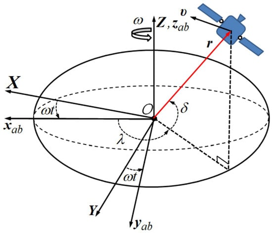
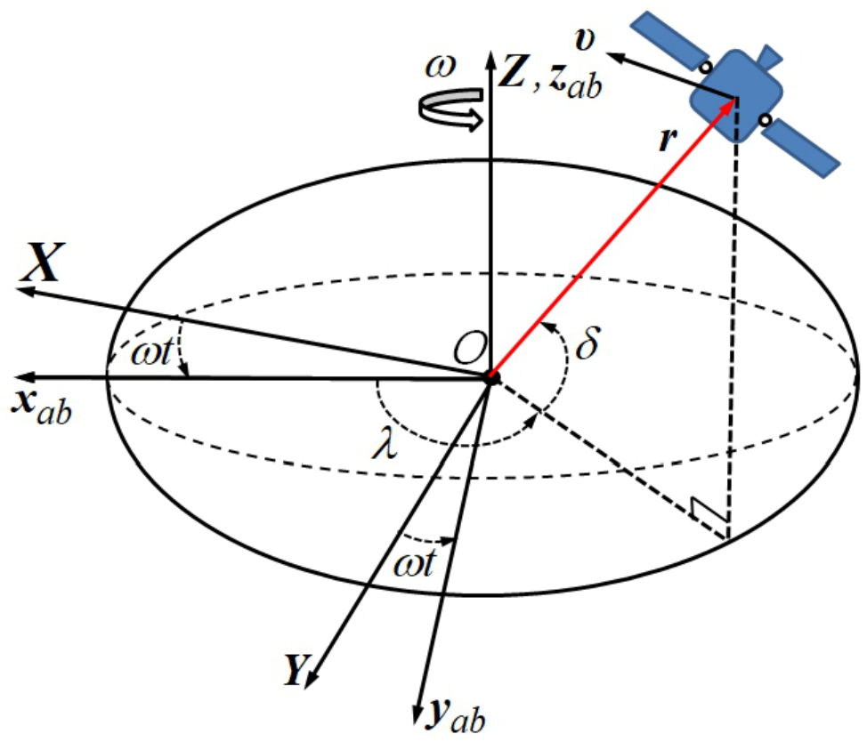
The asteroid hovering problem is formulated in the body-fixed frame of a uniformly rotating small body. Let denote an inertial reference frame centered at the asteroid’s center of mass, and let denote a body-fixed frame whose axes remain aligned with the asteroid. As illustrated in Figure 1, the unit vectors define the coordinate directions of , where coincides with the asteroid rotation axis.
Figure 1.
Body fixed coordinate system.
The control design in this paper is formulated for a spacecraft equipped with a multi-thruster translational actuation system. The controller first generates a desired continuous force or acceleration vector for hovering, and this command is subsequently mapped to nonnegative thrust levels associated with individual thrusters. Since the final implementation uses PWPF-modulated on–off thrust, the continuous dynamics in this section are used as the nominal control-design model, whereas actuator saturation and switching effects are explicitly addressed in Section 3.
The rotation is assumed to occur about the principal axis associated with the maximum moment of inertia at a constant angular velocity , yielding a rotation period of so that for a uniformly rotating asteroid. The translational dynamics of a spacecraft expressed in the asteroid body-fixed frame are
where and are the position and velocity vectors in the asteroid body-fixed frame, ; is the angular velocity of the uniformly rotating asteroid; is the asteroid’s gravitational acceleration; and are the solar radiation pressure acceleration and sun’s gravitational acceleration; is the control thrust command; is the perturbing acceleration accounting for unknown forces such as gravity field inaccuracies and third-body perturbations; is the magnitude of the control thrust vector, , and is the standard gravitational acceleration (9.81 m/s2). The thrust vector is then associated with the acceleration command by the conventional thrust-to-mass ratio . Equation (3) represents the net-force-norm mass-flow surrogate used for the tabulated simulation outputs, not the physical total propellant flow for independently fired thrusters. With six nonnegative thruster forces and equal , the physically consistent model is ; the two expressions coincide only in special cases without canceling or non-collinear thruster contributions. A simulation rerun using the physical model is needed before interpreting the reported consumed mass as hardware propellant expenditure. The non-trivial gravity field for studying dynamics in the vicinity of an asteroid [2] is given by
where is the gravitational parameter of the asteroid, is the distance from the body center of mass, is the latitude measured from the plane, and is the longitude measured from the long end of the body [13]. In Equation (4), denotes the second-degree, second-order contribution to the gravity potential in the body-fixed frame:
In Cartesian coordinates, the potential is expressed by [13]
where and are the body-fixed latitude and longitude; X, Y, and Z denote inertial position components. An inertial longitude is converted to the body-fixed longitude through the asteroid rotation angle and the adopted epoch convention. The first-order partial derivatives of the potential are
The local gravitational acceleration is
The perturbation accelerations due to solar radiation pressure (SRP) and solar gravity are modeled following the formulation in [14]. The SRP acceleration is given by
which represents the momentum transfer from incident solar photons to the spacecraft. This model adopts a cannonball approximation, in which the SRP force acts along the Sun–asteroid direction . The magnitude of the acceleration depends on the solar radiation constant , the spacecraft mass-to-area ratio , and the surface reflectance coefficient , which accounts for both absorbed and reflected photon momentum. The solar gravitational perturbation is expressed as
which corresponds to the third-body tidal acceleration induced by the Sun. This formulation captures the differential gravitational effect between the spacecraft and the asteroid, where denotes the spacecraft position vector relative to the asteroid and is the position vector of the asteroid relative to the Sun, both expressed in the asteroid-fixed frame . The solar gravitational parameter is .
Together, these perturbation models represent the dominant non-central forces acting on a spacecraft during proximity operations near a small body. Although nominal models of the asteroid gravity field, solar radiation pressure (SRP), and solar gravitational perturbations can be constructed, their accuracy depends strongly on uncertain asteroid and spacecraft properties, including the asteroid mass distribution, shape model, spacecraft mass, surface geometry, and optical characteristics. In practice, incomplete knowledge of the asteroid gravity field, spacecraft optical properties, and the surrounding space environment inevitably introduces modeling uncertainties in the gravitational, SRP, and solar-gravity accelerations. To account for these uncertainties and other unmodeled perturbations, all residual acceleration components are grouped into a lumped disturbance term
where , , and denote the modeling errors associated with the asteroid gravity field, solar radiation pressure, and solar gravitational perturbations, respectively, and represents any additional unmodeled environmental disturbances. This lumped representation enables the development of a disturbance-observer-based control framework without requiring detailed knowledge of individual perturbation sources. The relative translational dynamics in Equation (2) can therefore be expressed as
where
The lumped disturbance term encompasses all uncertain environmental perturbations and modeling errors that are not explicitly represented in the nominal dynamics. This formulation is particularly suitable for velocity-free hovering because the disturbance observer developed in the next section simultaneously reconstructs the unmeasured velocity states and the lumped disturbance vector from position measurements alone.
3. Velocity-Free Finite-Time Hovering Control with Multi-Thruster on–off Actuation
This section develops the proposed velocity-free finite-time hovering controller together with the multi-thruster on–off implementation used for practical spacecraft actuation. The design is organized around four mission-driven requirements: (i) hovering without direct velocity measurements, (ii) robustness against uncertain asteroid gravity and external disturbances, (iii) finite-time transient recovery, and (iv) compatibility with multi-thruster PWPF-modulated on–off thrust commands. The proposed architecture first employs a finite-time disturbance observer (FTDO) to reconstruct the unmeasured translational velocity and the lumped disturbance vector from position measurements. The observer output is then used by a nonsingular fast terminal sliding mode controller (NFTSMC) to generate a robust continuous hovering force. Finally, the continuous force command is allocated to a six-thruster translational actuation system and converted into realizable on–off commands through PWPF modulation. This organization intentionally treats the FTDO and NFTSMC as enabling components of a practical hovering framework rather than as isolated theoretical modules. The disturbance estimate reduces the uncertainty that must be rejected by the NFTSM reaching term, which permits smaller switching gains and smoother multi-thruster pulse commands. The PWPF implementation then provides a direct connection between the finite-time control law and realistic spacecraft propulsion hardware.
3.1. Finite-Time Control Preliminaries for Velocity-Free Hovering
This subsection summarizes the finite-time stability tools and nonsingular fast terminal sliding surface used to construct the velocity-free hovering controller. The controller derivation is presented in a form suitable for both continuous-thrust implementation and subsequent PWPF-compatible on–off thrust realization.
Lemma 1
(Du et al. [15]). If , then the following inequality holds:
Lemma 2
(Ye et al. [16]). For , , and , an extended Lyapunov condition for finite-time stability can be expressed as
where is a positive definite Lyapunov function. The associated settling time satisfies
Inequalities (17) and (18) imply that the closed-loop system exhibits both exponential stability and finite-time convergence properties [17]. These properties form the theoretical foundation for the NFTSM controller. For subsequent control design, the following vector notations are adopted:
where is a constant exponent and denotes the identity matrix.
For the body-fixed hovering state under finite-time control, the spacecraft is required to reach the desired relative position and velocity in finite time. This task is accomplished through a translational maneuver toward the commanded state. The position and velocity tracking errors are then defined as
To achieve the control objective, a non-singular fast terminal sliding mode (NFTSM) surface is introduced:
where
with design parameters satisfying , , , and . The simulations employ common scalar exponents across axes, whereas the diagonal matrices permit axis-dependent surface gains.
Lemma 3.
Consider the terminal sliding manifold defined in (23). If , then the system states are attained in finite time.
Theorem 1.
Consider the asteroid hovering dynamics in (1)–(3) in the absence of lumped and parametric uncertainties, i.e., . Then, the nominal reaching dynamics admit a finite-time Lyapunov comparison on trajectory intervals where the sliding input multiplier is uniformly positive. This is a conditional reaching statement; a separate nonsmooth argument is required at zero tracking velocity. The corresponding control law is:
where
with and . Here, represents the equivalent control that compensates nominal dynamics, while is the reaching control driving the states onto the sliding surface.
Proof.
Consider the Lyapunov candidate
Its derivative along (1)–(3) yields
Substituting (24) into (26) gives
where and are positive definite diagonal matrices for . From Lemma 1, one obtains
where and . Since , inequality (28) guarantees finite-time convergence of to zero by Lemma 2. The reaching time is bounded by the comparison formula in (18), with the positive lower bounds of the effective gains on the interval under consideration; this estimate does not apply where a multiplier degenerates. Finally, substituting (24) into (2) yields
The displayed dynamics give the intended nonsingular terminal feedback; however, they do not by themselves prove that every velocity-zero crossing has a uniform finite-time reaching rate. The uniform finite-time comparison applies only where the effective gain admits a strictly positive lower bound. Once the manifold is reached and maintained, Lemma 3 describes its nominal terminal dynamics. □
3.2. Velocity and Disturbance Reconstruction Using a Position-Only FTDO
The observer design follows the homogeneous higher-order sliding-mode differentiation framework [9,10,11], augmented with known spacecraft dynamics. It is not claimed that existing exact-differentiation theorems automatically cover the present state-dependent, regularized implementation. Let the body-frame translational dynamics and the available position-only navigation measurement be
where is the realized thrust acceleration, and denote navigation-position bias and noise, and is the lumped unknown acceleration defined relative to the chosen nominal acceleration model. This lumped quantity may differ from the prescribed external acceleration used in the simulation when the nominal and propagation models are not identical. In the body-fixed case, the nominal model used by the observer takes the form
The corresponding inertial-hovering implementation omits the rotating-frame terms. The nominal accelerations are evaluated using the observer states; the corresponding gravity and solar-perturbation routines must be consistent with those implemented in the simulation. The notation here represents the residual between the true and nominal accelerations and may thus include both the explicitly prescribed external acceleration in Equation (70) and unmodeled gravity or solar perturbations. Hence, the FTDO estimate should not automatically be interpreted as an isolated estimate of the injected acceleration alone. Let , , and . With the position innovation , the ideal nonsmooth observer is
where ⊙ denotes componentwise multiplication, , , and componentwise. Scalar gains are included by taking equal elements in each . Crucially, the correction requires neither true velocity nor navigation velocity. The nominal force model uses observer states, and the actuation input is evaluated after thrust saturation, allocation, and any PWPF realization. In the provided code, the observer evaluates the gravity and solar perturbation terms at and constructs the rotating-frame term using for body-fixed hovering. The corresponding inertial-mode branch sets this rotating-frame term to zero.
For noisy sampled navigation, the implementation in ftdo_pos.m employs the regularized functions
Replacing the three signed-power maps in (33) by their corresponding yields the implemented regularized observer. The three corrections are locally linear near zero innovation; thus, positive mitigates discontinuous switching but generally removes the exact finite-time convergence property of the ideal design. The gain and smoothing values are tuning parameters, not a substitute for a validated noise/error bound. Their choice can differ by axis to reflect measurement quality and nominal acceleration uncertainty.
Assumption 1.
The trajectory remains in a compact, collision-free operating domain; is locally Lipschitz on that domain; the realized acceleration is supplied consistently to the observer; and the derivative of the lumped disturbance satisfies . Any ideal finite-time claim further requires suitable third-order differentiator injection and gain conditions in the presence of the state-dependent nominal-model mismatch.
With , , , ideal noise-free estimation errors satisfy
The nominal-model difference in (35) cannot be omitted for the nonlinear rotating-frame plant. Classical ideal finite-time results apply directly only after their disturbance-regularity and robust gain hypotheses are verified [10]; these hypotheses have not been established solely from the gains used in the present simulation.
Proposition 1.
Consider one axis of the regularized observer near zero innovation, with unbiased noise-free position measurements, locally constant disturbance, and negligible first-order nominal-model mismatch. Define
The linearized position–velocity–disturbance estimation-error subsystem is asymptotically stable if and ; equivalently, .
Proof.
The locally linearized observer errors satisfy , , and . Their characteristic polynomial is . The stated inequalities are precisely the Routh–Hurwitz conditions for this cubic. This result is local and for the simplified linearization; the full spacecraft nominal-model Jacobian may change the stability condition. □
- Explicit local observer-error estimate. Define . In a neighborhood where the regularized innovation is differentiable, the error dynamics admit the local representationwhere includes the Jacobian of along the considered trajectory (and the regularized correction slopes), and contains bounded measurement errors and bias, , numerical/sampling effects, and any model-input mismatch. Assume the linearized transition matrix satisfies , , and the higher-order remainder is locally absorbable into its decay margin. If , the variation-of-constants estimate, with suitably adjusted positive , yieldsThis is a conditional local error estimate, not a gain-independent claim for the nonlinear observer. A sufficient verification is a common and satisfying over the operating neighborhood, with the nonlinear remainder accounted for. The one-axis Routh–Hurwitz condition of Proposition 1 does not itself verify this full coupled condition. Equation (38) supplies explicit component bounds through . After the observer transient , a conservative common choice is .
Gaussian position noise is unbounded in amplitude; thus, a deterministic does not hold for its entire distribution. Equation (38) instead applies to explicitly bounded measurement realizations or specified high-probability noise events. Under the stated sampled Gaussian simulation, error RMSE and sample-path maxima must be reported from simulation logs and cannot be inferred from this theorem.
Remark 1.
The proposed NFTSMC–FTDO uses and for position and velocity feedback, respectively, and for compensation. The two baseline controllers may use navigation-velocity feedback, but no measured or navigation velocity enters the proposed observer.
3.3. Disturbance Compensation and Switching-Gain Reduction
The proposed NFTSMC command contains a model-based feedforward term, a saturated disturbance-compensation term , and nonlinear reaching feedback. Because estimates residual acceleration relative to the nominal model, the controller must apply nominal-acceleration compensation and observer-based disturbance compensation without double counting the same physical term. The disturbance-compensation target is the lumped residual defined in (30), not merely an injected simulation signal.
If the observer achieves an error bound on the intended operating domain, the reaching term need reject this residual rather than the entire modeled-plus-unmodeled environmental acceleration. This can permit smaller robust-control gains if other error sources are also bounded and actuator authority is sufficient. Lower switching gains may reduce force-command variability, but less propellant use or fewer PWPF firings does not follow automatically: those quantities depend on the thrust allocation, pulse realization, and disturbance dynamics.
The uncertainty entering the tracking analysis contains both the disturbance-estimation residual and the effects of using and rather than the true state. During initial observer transients, the bounds may be larger than their eventual practical values. Consequently, the analysis in the next subsection is conditional on admissible observer-error bounds and does not assume perfect disturbance cancellation. Reference formulations for sliding-mode estimation and its robustness limitations are given in [10,11,18]; the latter concerns the super-twisting algorithm and is not a direct stability theorem for the present third-order observer.
3.4. NFTSMC–FTDO Velocity-Free Hovering Control Law
For the proposed third comparison controller, the observer-estimated tracking variables are defined consistently with (33):
Here, is a velocity estimate, not measured velocity; is used internally as the observer’s estimated position. Thus, the commanded thrust is
In this expression, denotes the lumped-acceleration estimate, . In the numerical implementation, it is clipped componentwise by the limit before compensation, so the implemented command replaces with ; any clipping residual contributes to the disturbance term in the stability analysis. Equation (41) denotes the ideal commanded force, whereas the observer propagates the realized acceleration .
Theorem 2.
Consider (30) with the controller (41). Suppose the trajectory remains in a compact admissible hovering domain, the reference and nominal dynamics are smooth, and the observer errors satisfy (39) for . Suppose further that the sliding-surface input multiplier
obeys on the portion of the trajectory used in the reaching estimate. If the combined acceleration and feedback perturbation is bounded by , then the true sliding variable enters in finite time any set
under ideal continuous thrust with no further input saturation. Exact finite-time convergence of the tracking errors follows only in the zero-residual case and under the nominal sliding-manifold reachability conditions. For nonzero observer and actuation residuals, bounded sliding motion alone does not specify a position–velocity bound without a corresponding robustness property of the sliding dynamics.
Proof.
Subject to the stated representation of the combined estimated-feedback and actuation residual, the true sliding variable satisfies, almost everywhere,
where collects the model, disturbance-estimation, state-feedback, and realized-actuation mismatch after accounting for the difference between the estimated and true surface. Such a representation, with the stated bound, is conditional on bounded errors and local regularity of the nonlinear maps. With , Lemma 1 and the assumed multiplier bounds imply
Outside (43), the final term is less than one-half of the terminal reaching term; consequently , ensuring finite-time entry into the stated residual set. If , this comparison yields ideal finite-time surface reaching; on the manifold, the standard NFTSM surface dynamics yield finite-time tracking under their regularity assumptions. If , the result establishes only practical surface reachability. A compact tracking-error neighborhood additionally requires local input-to-state/practical stability of the reduced-order error dynamics. □
- How the surface radius relates to physical tracking. The estimated-feedback and acceleration mismatch can be conservatively budgeted asprovided are verified local Lipschitz constants of the feedback (including the nonlinear sliding surface), and the residual terms are evaluated consistently in acceleration units. This is a bound template; no numerical value is asserted without verified constants. Moreover, alone does not imply a computable bound on . If the perturbed reduced tracking dynamics are locally ISS and admit a verified estimatethen . The gain must be established for the reduced dynamics; this manuscript does not infer a numerical position-error radius from in the absence of such verification. In particular, near , the nondegeneracy fails, and the reaching theorem cannot be extended globally by continuity.
Remark 2.
For , vanishes in a channel at . Thus, the uniform condition is not global and the above theorem is a conditional reaching estimate, not a proof of global finite-time convergence. A full theorem at zero velocity would require a dedicated nonsmooth/degenerate-manifold argument or a modified reaching law. Sensor noise, saturation, and PWPF switching also preclude unconditional exact finite-time convergence.
The control command is saturated per axis as
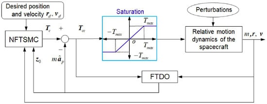
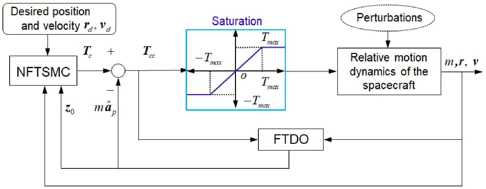
with . Saturation can add the residual to ; therefore, nominal reaching proofs apply without modification only when the commanded force is feasible or that additional residual is explicitly bounded. The continuous-thrust architecture is shown in Figure 2.
Figure 2.
Observer-based hovering control architecture with position-only measurements, realized-actuation feedback, and saturation.
3.5. Application to Inertial Hovering with on–off Actuation
The velocity-free control design developed in the previous subsection can be extended to achieve inertial hovering with respect to an asteroid. At , assume coincides with . The transformation matrix from to is
where is the asteroid’s rotation rate. The transformation matrix from to is given by . For any vector expressed in , its inertial components satisfy .
The translational dynamics of the spacecraft relative to are given by
where , and the other terms denote nominal solar radiation pressure, solar perturbations, control acceleration, and the lumped disturbance, respectively. Compared with the body-fixed dynamics, the inertial-frame formulation eliminates Coriolis and centrifugal terms, as in . The control law for inertial hovering can then be written as
where
Here, , , and (with consistent model-mismatch accounting). The estimated inertial tracking errors are and . The nominal inertial acceleration is evaluated from the transformed nominal asteroid gravity, SRP, and solar acceleration without rotating-frame Coriolis or centrifugal terms. The reference acceleration is .
3.6. PWPF-Compatible on–off Thrust Command Generation
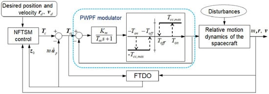
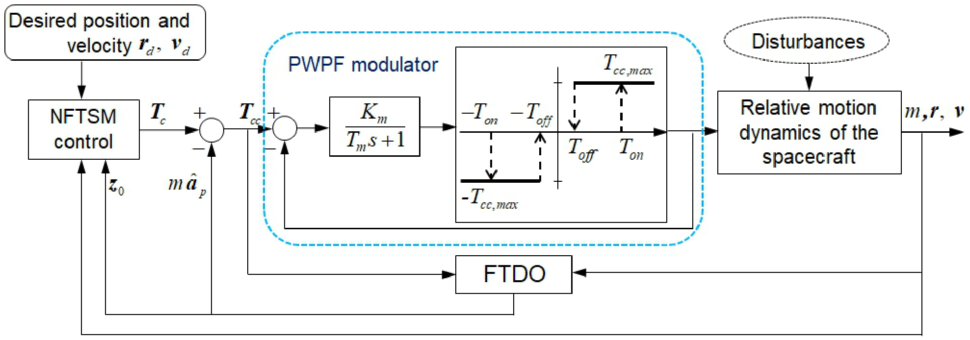
The hovering controllers developed thus far generate continuous acceleration commands. In practice, however, the realizable actuation depends critically on the spacecraft propulsion subsystem. Many small-body exploration spacecraft employ chemical or cold-gas thrusters that provide discrete on–off commands rather than continuously variable thrust levels. To accommodate this constraint, the proposed finite-time control law in Equation (41) is used as the continuous acceleration command input to a pulse-width pulse-frequency (PWPF) modulator. This configuration enables practical finite-time hovering using on–off thrusters while maintaining high control accuracy and robustness.
As illustrated in Figure 3, the PWPF modulator consists of a feedback loop composed of a linear first-order filter and a Schmitt trigger [6,19]. The continuous control acceleration command from Equation (41) is compared with the modulator output, and the resulting error is processed through the filter–trigger interconnection. The Schmitt trigger subsequently converts the filtered signal into a binary on–off pulse sequence suitable for thruster actuation, where each thruster delivers the maximum control acceleration . The parameters and denote the loop gain and filter time constant, respectively, while and represent the upper and lower switching thresholds of the Schmitt trigger, and defines the maximum achievable control level. Proper tuning of these parameters allows the modulator output to closely reproduce the desired continuous control command while enforcing the discrete on–off firing characteristics of the propulsion system. The integrated control architecture combining the FTDO, NFTSMC, and PWPF modulator is shown in Figure 3. In this configuration, the observer-based controller generates a continuous command that is transformed by the PWPF modulator into a physically realizable pulse sequence, thereby enabling precise position and attitude regulation during hovering operations.
Figure 3.
Block diagram of the proposed hovering control system incorporating FTDO, NFTSMC, and PWPF modulation.
Remark 3.
PWPF modulation maps continuous commands to hysteretic on–off pulses and can prevent direct high-frequency switching of ideal sliding-mode commands. This does not, by itself, establish reduced ignition counts, propellant use, or a small pointwise acceleration error. The realized pulse sequence must be assessed under the selected thresholds, sampling, thruster limits, and allocation method. Accordingly, the stability analysis treats PWPF realization error as a bounded perturbation when a bound can be established.
3.7. PWPF Modulation and Practical Finite-Time Stability
The six-thruster PWPF unit is driven by the allocated nonnegative per-thruster commands, not directly by a signed three-axis force. For each thruster channel , let denote the allocated continuous command and the realized on–off force. A first-order filter and hysteretic Schmitt trigger may be represented as
where and . The holding branch is essential to the hysteretic implementation. If D is the body-axis force allocation matrix, the actual body-frame control acceleration is (after any thruster/attitude transformations), whereas the commanded acceleration is . Consequently, the acceleration realization residual is
The first term is the pulse-modulation residual; the second accounts for allocation and saturation. In particular, an instantaneous binary PWPF output need not closely follow the continuous command at each sample, even when its time-averaged effect is satisfactory.
Assumption 2.
On the admissible simulation interval, the spacecraft mass is bounded below by , individual thrusts obey , and the observer error remains bounded after a finite transient. The sampled closed-loop trajectory remains in the domain of Theorem 2, and the combined acceleration/feedback residual obeys . This bound includes observer errors, noise, model evaluation errors, saturation, control allocation, and PWPF residuals; its value must be assessed from the implemented parameters and reachable control commands.
A conservative instantaneous bound following only from thrust limits and a bounded commanded force is
where . This is deliberately conservative and does not imply that PWPF gives small instantaneous error; a tighter bound requires a duty-cycle/sampling analysis or direct numerical characterization for the specified .
Theorem 3.
Under Assumption 2 and the conditional nondegeneracy assumption of Theorem 2, the sliding variable of the observer-based, PWPF-actuated closed loop reaches in finite time a neighborhood satisfying (43). If the reduced-order tracking error dynamics are locally practically input-to-state stable with respect to the resulting sliding perturbation, the position and velocity tracking errors are ultimately bounded on the same admissible hovering domain. No exact finite-time convergence of the noisy, sampled, saturated on–off system is asserted.
Proof.
Substitution of the applied thrust into the plant yields the residual (57), which is included in in (44). The finite-time entry estimate then follows from (45) on the domain where . Practical stability of the tracking state follows under the additional stated reduced-order stability property; it is not implied merely by bounded . □
Remark 4.
The residual set depends on position-noise bias and amplitude, velocity and disturbance estimation errors, sample time, observer boundary layer, and the actual actuator implementation. Reducing PWPF hysteresis or increasing switching frequency can change the average tracking error, but neither operation alone guarantees a monotonic reduction of the instantaneous residual or propellant expenditure. The final numerical study therefore reports performance rather than interpreting the practical bound as an empirically validated sharp threshold.
3.8. Six-Thruster Force Allocation for on–off Hovering
A six-thruster translational configuration is considered to represent opposing actuation along the three body axes. The six-channel geometry provides opposing force directions along each translational axis. The corrected constraint-consistent allocator is derived below, while the historical simulation tables were generated using an earlier force-realization implementation. The corresponding net force may differ from the unconstrained controller demand because of saturation and pulse modulation.
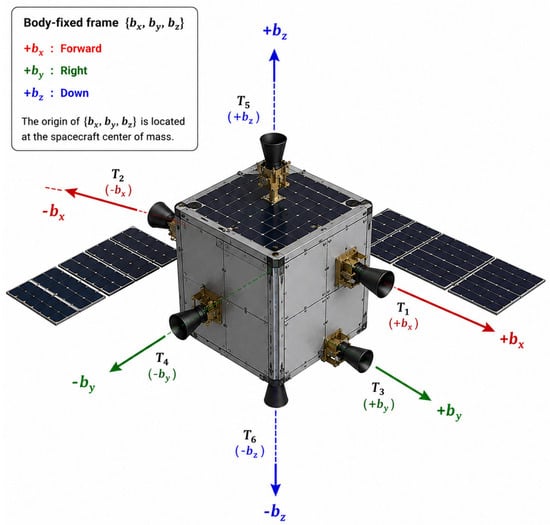
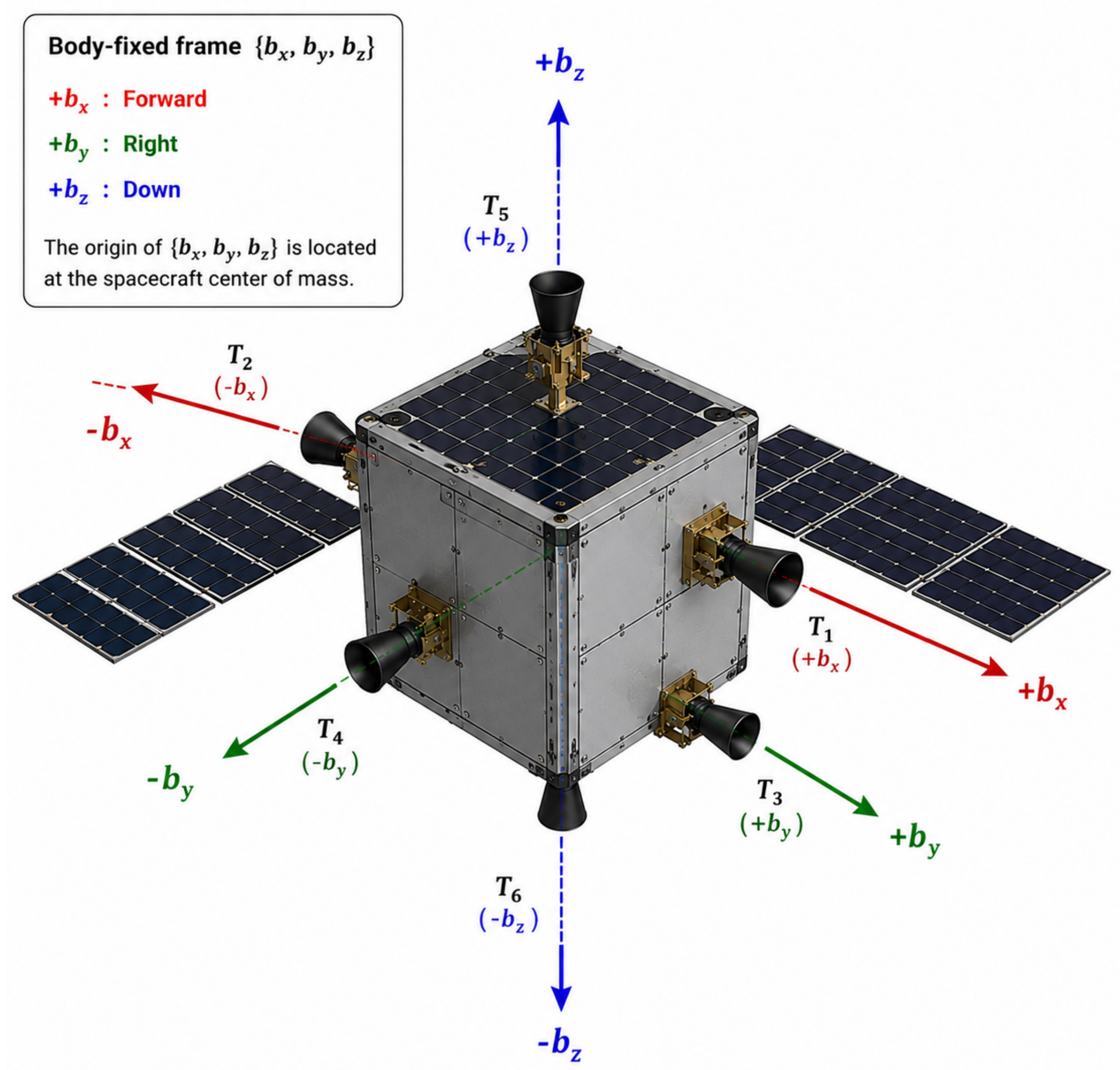
The spacecraft is equipped with six low-thrust propulsion units arranged as three opposing thruster pairs along the body-fixed axes. The body-fixed reference frame is defined as , with the origin located at the spacecraft center of mass. The idealized geometry is assumed to produce translational forces through the center of mass; attitude-coupling errors are outside the present model.
Figure 4 illustrates the proposed six-thruster spacecraft configuration and the associated body-fixed reference frame. Three opposing thruster pairs generate translational forces along the , , and directions, respectively.
Figure 4.
Illustrative six-thruster spacecraft configuration in the body-fixed frame. Three opposing thruster pairs generate translational control forces along the , , and directions for asteroid hovering maneuvers.
The six thrusters are organized into three opposing pairs as summarized in Table 1. The ordering in the supplied MATLAB allocation matrix is along , along , and along . This order is used below so that the reported six-channel thrust histories correspond to the actual simulation commands.
Table 1.
Six-thruster configuration for three-degree-of-freedom translational maneuvering.
The corresponding unit thrust direction vectors, ordered consistently with the simulation code, are
The total body-frame control force generated by the six thrusters is expressed as
where denotes the nonnegative force of the ith thruster; in continuous allocation , while under on–off operation .
Defining the thruster command vector as
the translational control force can be compactly represented by
where the translational allocation matrix is defined as
For the desired translational control force generated by the proposed hovering controller,
The physically constrained allocation is the bounded least-squares problem
For the equal-limit, orthogonal opposing pairs in Equation (63), a closed-form solution is obtained without a numerical optimization routine. Define and the scalar clipping (saturation) operator by for . Thus, clipping leaves x unchanged when , returns a when and returns b when . Applied independently to each body-axis force component, the saturation is
The six nonnegative continuous commands, in the ordering , are
Every component satisfies . Since , the continuous allocation residual is exactly
Thus, for every feasible desired force within the box , and Equation (67) solves the constrained least-squares problem for arbitrary force demands in this ideal geometry. In contrast, because , pseudoinverse allocation followed by nonnegative clipping produces only whenever and the corresponding channel is not saturated. This identifies a structural loss of commanded force, not a mere tuning effect.
The continuous allocation residual and the on–off realization residual must be measured separately:
For equal per-channel binary limits, , giving the conservative instantaneous bound . It is not a duty-cycle average bound. Quantitative validation should report , its maximum, and the analogous RMSE/maxima of in new simulations employing this allocator. These numerical statistics are not available from the supplied manuscript alone; historical trajectory and propulsion metrics below are retained as results of the previous implementation and are not claimed to validate the revised allocation.
The proposed six-thruster configuration provides several practical advantages for asteroid hovering missions. First, the architecture enables independent translational maneuvering along all body axes without requiring large spacecraft reorientation maneuvers. Second, opposing thrust directions provide the ability to generate positive and negative force along each axis, although fault-tolerant reallocation after a thruster failure is not implemented or demonstrated here. Third, the architecture permits continuous saturated-force and discrete on–off command studies with the same geometry. The 170 s specific impulse and 20 N per-channel thrust adopted here are illustrative actuator parameters; no particular electric or cold-gas flight hardware has been validated. The effect of allocation residuals is therefore relevant when interpreting the numerical results.
Assumption 3.
In this study, the spacecraft attitude is assumed to be regulated such that the spacecraft body-fixed frame remains aligned with the asteroid body-fixed frame during hovering operations. Under this assumption, the six-thruster propulsion system is utilized exclusively for three-degree-of-freedom translational maneuvering, while the attitude dynamics and attitude control system are neglected. Consequently, the commanded control forces generated by the hovering controller can be directly applied along the body-fixed axes without requiring additional attitude reorientation maneuvers.
Remark 5.
The complete control-to-actuator chain is therefore: position measurement → FTDO-based velocity and disturbance reconstruction → NFTSMC continuous force command → multi-thruster force allocation → PWPF-modulated on–off thrust. This sequence reflects the intended implementation focus of the proposed method.
4. Numerical Simulations
This section compares three hovering controllers under the specified gravity, navigation-error, disturbance, and actuator models. The body-fixed study uses continuous thrust; the inertial study uses simulated PWPF on–off thrust. These numerical studies assess scenario-specific tracking and modeled propulsion expenditure rather than establishing global robustness or hardware-level actuator feasibility. Asteroid 433 Eros is selected as the representative target body because of its highly irregular gravity field and its widespread use as a benchmark in asteroid-hovering studies. The asteroid is modeled as a uniformly rotating triaxial ellipsoid with principal-axis dimensions of km (semi-axes of , , and km) [20]. The second-degree gravity harmonic coefficients are chosen as km2 and km2, representing the dominant oblateness and ellipticity characteristics of the asteroid. The orbital and physical properties employed throughout the simulations are summarized in Table 2.
Table 2.
Orbital and physical properties of asteroid 433 Eros.
Two representative hovering scenarios are considered to evaluate both continuous-thrust and on–off thrust implementations. The first scenario investigates body-fixed hovering near an equatorial equilibrium point using continuous-thrust actuation and is intended to assess the effectiveness of velocity-free state reconstruction, disturbance rejection, and tracking behavior under uncertain environmental conditions. The second scenario considers inertial hovering above the asteroid north pole using PWPF-modulated multi-thruster on–off actuation and focuses on practical implementation issues, including switching behavior, propellant utilization, and hovering accuracy under the specified actuator limits.
The spacecraft initial mass is selected as kg. The modeled propulsion system consists of six independently controlled thrusters that provide translational control authority in three-dimensional space. Each thruster is capable of producing a maximum thrust of 20 N and has a specific impulse of s. The same allocation geometry is used for continuously saturated thrust and the on–off PWPF mode. The performance tables have been updated using the newly supplied simulation indices. Independent allocation-residual statistics and confirmation that the existing time-history figures correspond to those runs remain necessary. The implementation assumes constant specific impulse and a maximum force of 20 N for each thruster. The solar radiation pressure acceleration uses a mass-to-area parameter kg/m2 and a reflectance factor . These values are distinct from the navigation and control gains. To evaluate performance under realistic navigation conditions, a stochastic measurement model is introduced. Position navigation errors are generated independently on each axis as a constant m bias plus zero-mean Gaussian noise with a standard deviation of m. Direct velocity measurements are not utilized by the proposed controller. Instead, the finite-time disturbance observer reconstructs the required velocity information from position measurements alone, thereby emulating realistic velocity-degraded hovering scenarios encountered during autonomous small-body operations.
To assess robustness against the uncertain environment of a rotating small body, gravity-field modeling errors, unmodeled solar radiation pressure effects, and slowly varying acceleration perturbations are considered. Although the driver defines an alternative coefficient vector c_vec_nominal, the current controller routines evaluate their gravity terms using c_vec, while the proposed observer evaluates gravity through gravity_acc at the observer-estimated position. Consequently, the prescribed coefficient mismatch is not activated as a separate nominal-gravity test in this ZIP. In addition to any state-dependent discrepancies, the spacecraft propagation is subjected to the following explicitly prescribed external acceleration , consistent with the MATLAB implementation:
where is expressed in seconds and all terms in have units of . The first vector represents a small fixed acceleration bias; the second contains deterministic first- and second-harmonic fluctuations synchronized with the approximately h rotation of 433 Eros; and the third is a small periodic proxy for residual solar radiation pressure (SRP) uncertainty. The fourth term is a zero-mean, temporally correlated stochastic acceleration, generated in discrete time as
with . Thus, the stochastic component has an exponential correlation time of 600 s and approaches the specified per-axis stationary standard deviation after its initialization transient; it is not independent white acceleration noise at every sample. A fixed pseudorandom seed is used for reproducibility.
This disturbance construction is a representative robustness-test model, not a flight-calibrated reconstruction of the exact perturbing forces at Eros. Its validity for the present numerical study follows from three physical and numerical considerations. First, the dominant periodic terms vary at the asteroid spin frequency and its second harmonic, supplying smooth, slowly varying errors characteristic of body-fixed gravity-model and geometry-related mismatches. Second, the deterministic amplitudes are of order , while the SRP proxy and stochastic terms are respectively of order and ; these separated scales provide a controlled test of disturbance estimation over multiple time scales without asserting that the individual terms are uniquely identifiable physical accelerations. Third, the correlated stochastic term represents persistent residual model errors more plausibly than sample-independent acceleration noise. The chosen values are engineering assumptions for controller evaluation and should be varied in sensitivity and Monte Carlo analyses before drawing mission-specific performance conclusions.
The prescribed is injected into the spacecraft dynamics, whereas the disturbance reconstructed by the FTDO can also contain residual gravity, SRP, and third-body model discrepancies. Consequently, the estimated disturbance need not coincide exactly with the prescribed when the nominal and propagation models differ. Moreover, a sampled stochastic Ornstein–Uhlenbeck realization is not classically differentiable in continuous time; therefore, the bounded-disturbance-derivative hypothesis of an ideal finite-time observer cannot be claimed solely from this noise model. The regularized, sampled FTDO is instead assessed through practical estimation and tracking accuracy in the numerical simulations.
The three compared controllers are an asymptotic tracking controller (ATC), stand-alone NFTSMC using navigation position and velocity, and the proposed NFTSMC–FTDO using measured position and observer-estimated velocity. The navigation-velocity NFTSMC–FTDO variant is not included in the current simulation code or performance tables. The use of shared navigation-error samples and the same imposed external-acceleration history provides a consistent basis for the three-model numerical comparison. The asymptotic tracking controller (ATC), modified from Equation (24b) to achieve asymptotic convergence, is given by
where is the asymptotic feedback gain. This expression matches the acceleration command formed in x_dot.m before six-thruster allocation and saturation.
ATC and stand-alone NFTSMC use navigation velocity with a per-axis bias of m/s and independent Gaussian noise of standard deviation m/s, as implemented in the current driver. By contrast, the proposed controller obtains its velocity-feedback signal from the position-only FTDO and does not use the navigation-velocity channel; that channel is generated in the simulation for baseline control cases only. The true velocity is retained solely in the propagation and post-processing of observer errors. Consequently, the simulation study enables a direct assessment of the advantages provided by velocity-free state reconstruction, observer-based disturbance estimation and compensation, robust finite-time tracking, and PWPF-modulated multi-thruster on–off actuation under the simulated asteroid environment.
All controller and observer parameters are summarized in Table 3. For the NFTSMC-based controllers, the discontinuous signum function is replaced by a continuous saturation function [21] to reduce chattering, improve actuator compatibility, and facilitate implementation with PWPF-modulated on–off thrusters.
Table 3.
Controller, position-only observer, and PWPF parameters used in the three-case MATLAB simulation.
The menu selections used for the two reported studies are equatorial station/body-fixed/continuous thrust and north-pole station/inertial/PWPF on–off thrust, respectively. The ZIP offers these selections interactively; users must select them to reproduce the reported configurations. All simulations are conducted over one complete rotation period of asteroid 433 Eros, corresponding to approximately h. The nonlinear translational equations of motion are numerically integrated using a fixed-step fourth-order Runge–Kutta scheme with a sampling interval of 1 s. In the current implementation, the PWPF function is invoked from the right-hand-side function during the Runge–Kutta evaluations and maintains persistent filter/switch states. Thus, the current pulse histories represent the implemented numerical realization; a stage-consistent once-per-controller-sample PWPF update and independent modulator states for each controller are needed before attributing the results to a physically sampled propulsion system. The retained results characterize the simulated thrust histories and propulsion expenditure rather than validated ignition counts or physical pulse statistics. Furthermore, the mass-flow routine uses , based on the norm of the net translational thrust rather than the sum of the individual thruster force magnitudes. The tabulated consumed mass is therefore the reported output of this model and should not be interpreted as an independently validated multi-thruster propellant budget. The numerical comparisons report terminal position and velocity tracking errors, velocity and disturbance estimation diagnostics, the code-reported cumulative index, and model-based consumed mass. Because and mass may reflect different thrust norms or integration conventions, their numerical relation must be confirmed directly from the simulation code and logged force histories before both are interpreted as a consistent physical propellant budget. The six-thruster time histories illustrate the implemented actuation; detailed ignition counts and switching-rate statistics are not reported.
The following two simulation scenarios are designed to highlight complementary aspects of the proposed framework. The first scenario considers body-fixed hovering with continuous-thrust actuation and focuses on velocity-free state reconstruction, disturbance rejection, and tracking behavior. The second scenario investigates inertial hovering using PWPF-modulated multi-thruster on–off actuation and evaluates practical implementation characteristics, including switching behavior, propellant utilization, and hovering accuracy under the specified actuator limits. Together, these studies provide two complementary numerical demonstrations of the proposed position-only feedback architecture under continuous and simulated on–off actuation.
4.1. Body-Fixed Hovering Under Continuous-Thrust Actuation
The first study compares asymptotic tracking control (ATC), stand-alone NFTSMC, and NFTSMC augmented with the position-only finite-time disturbance observer (FTDO) for continuous-thrust hovering near 433 Eros. The spacecraft is initialized in the asteroid-fixed principal-axis frame at
The desired body-fixed hovering position is km, located 10 km outward from the modeled major-axis surface, with zero desired relative velocity. Consequently, the maneuver comprises a large initial transfer followed by regulation about a stationary point in . For all three methods, the same modeled asteroid environment, external acceleration disturbance, and continuous six-thruster actuation architecture are considered. In the proposed controller, the FTDO corrects its internal states using measured position only; its estimated velocity and lumped disturbance acceleration supply the velocity-feedback and disturbance-compensation terms of the NFTSMC law. The simulated true velocity is used to assess estimation accuracy, not to construct the observer innovation.
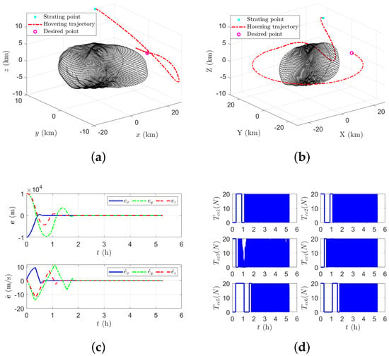
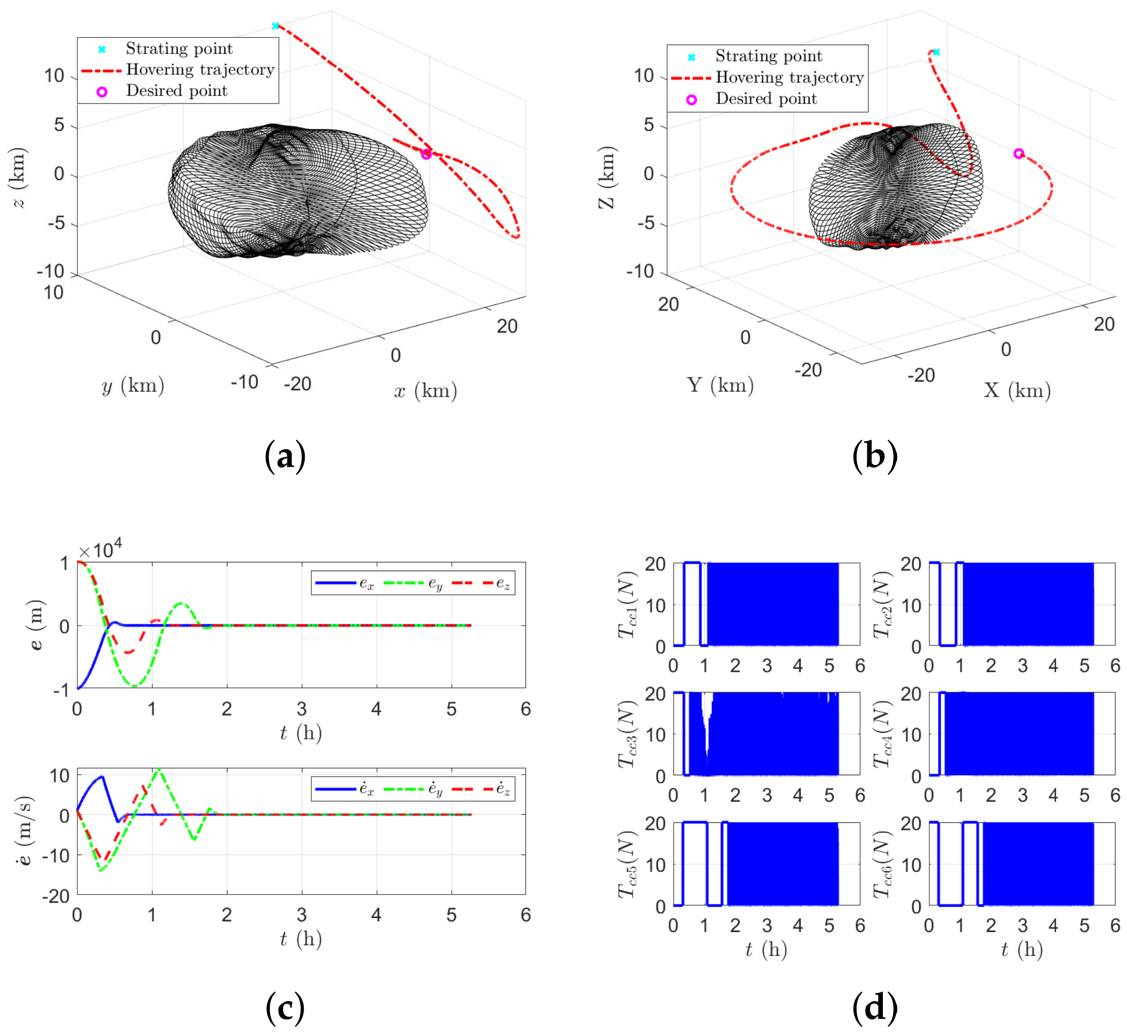
Figure 5 summarizes the maneuver geometry and the response of the proposed controller. The asteroid-fixed trajectory in Figure 5a illustrates the approach to the specified fixed hovering position; Figure 5b provides its inertial-frame counterpart. The distinction is physically important: a point fixed relative to the rotating asteroid does not correspond to a fixed inertial position. Figure 5c shows the position and velocity tracking histories, while Figure 5d displays the individual continuously commanded thruster forces after six-thruster allocation. These individual commands rather than the ideal unconstrained translational acceleration alone, characterize the implemented actuation demand. In particular, the actual acceleration entering the observer should be obtained from the realized allocated thrust to maintain consistency between the observer model and the simulated spacecraft dynamics.
Figure 5.
Body-fixed hovering under continuous-thrust actuation: (a) spacecraft trajectory in the asteroid-fixed frame ; (b) corresponding trajectory in the inertial frame ; (c) position and velocity tracking errors; and (d) allocated commands to the six thrusters.
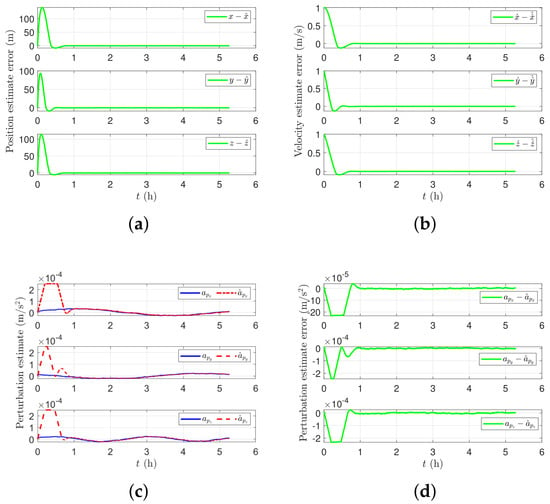
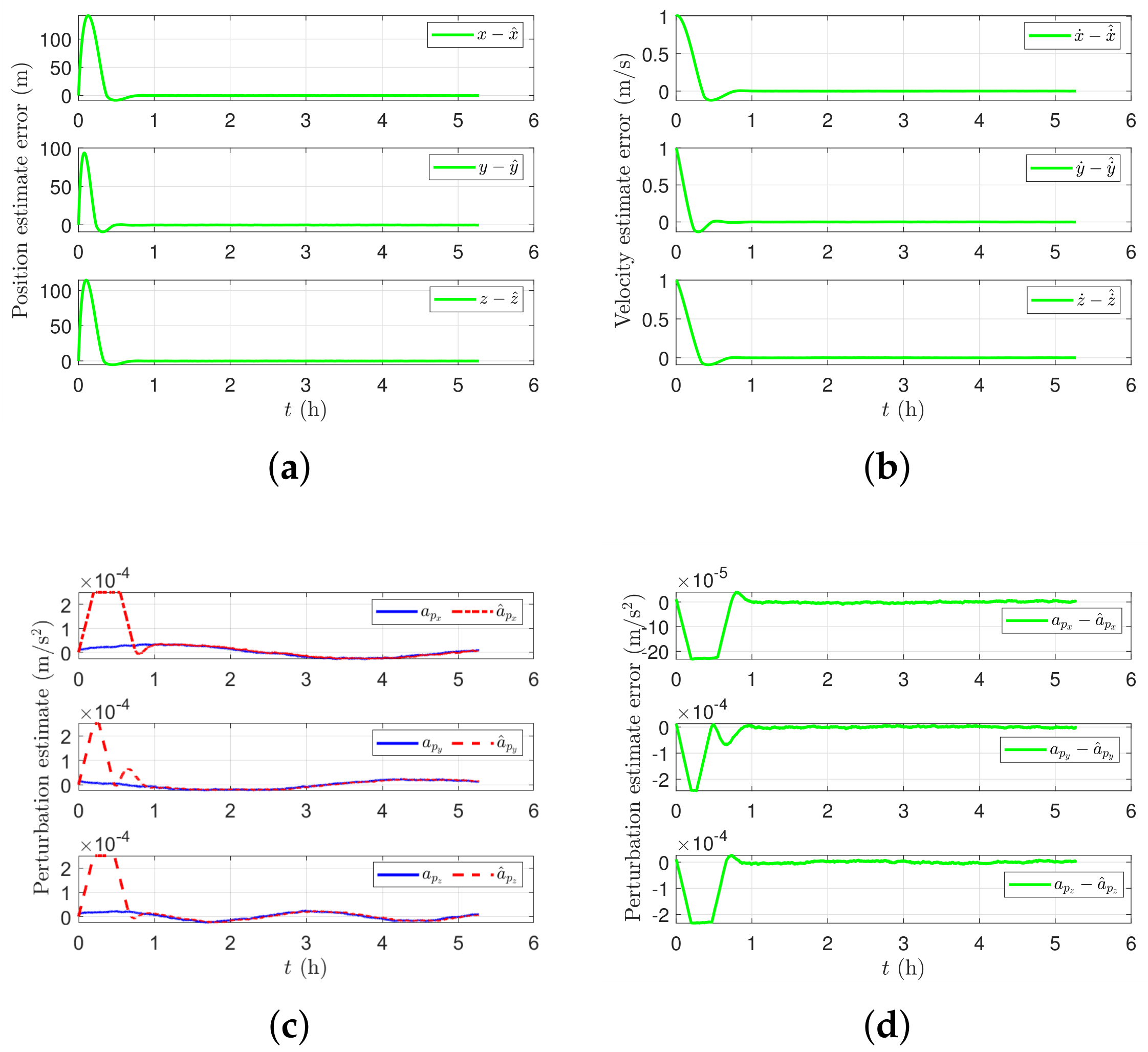
Figure 6 presents the position, velocity, and acceleration-disturbance observer diagnostics. The position and velocity traces in Figure 6a,b are relevant to assessing whether the position-driven observer supplies useful feedback during both the initial transient and the subsequent hovering phase. The velocity estimate is generated from the third-order observer dynamics, not from a measured velocity channel. Figure 6c,d respectively compare the simulated perturbation and its estimate and show the associated estimation error. Here, the observer state represents the lumped acceleration discrepancy between the true translational dynamics and the observer’s nominal model. Differences between and the prescribed external disturbance may therefore also reflect nominal gravitational or other modeling errors and should not automatically be attributed to a failure to reconstruct alone.
Figure 6.
Position-only FTDO diagnostics for the proposed controller: (a) position reconstruction; (b) velocity reconstruction; (c) estimated and simulated disturbance accelerations; and (d) disturbance-estimation errors. The disturbance estimate represents lumped acceleration uncertainty and need not coincide exactly with the prescribed external perturbation.
The observer diagnostics indicate the transient nature of state and disturbance reconstruction, but the figures by themselves do not establish exact finite-time convergence. In particular, measurement noise, continuous regularization of the signed-power injection, and numerical integration preclude an unconditional zero-error claim. Accurate velocity reconstruction and a sufficiently small lumped-disturbance estimation residual are the relevant practical requirements for the subsequent feedback control; quantitative observer accuracy should be supported by the corresponding estimation-error histories or computed RMSE values rather than inferred solely from overlap of plotted curves.
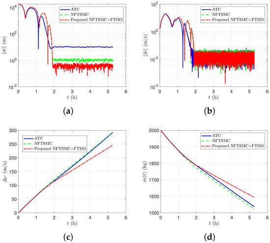
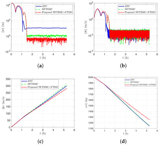
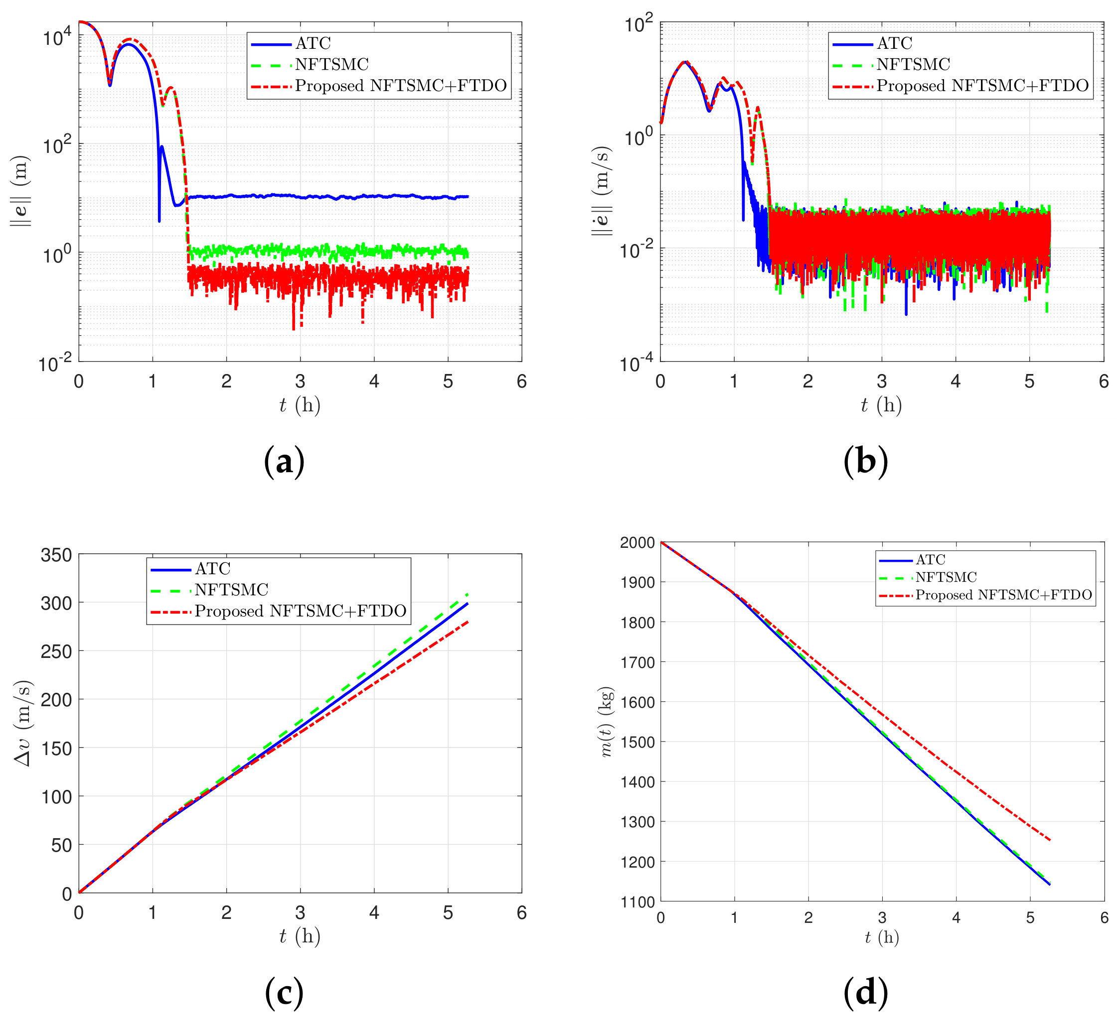
Figure 7 compares the three retained controllers through the norms of their position and velocity tracking errors, cumulative velocity increment, and spacecraft mass histories. Table 4 gives the updated quantitative indices. The proposed position-only NFTSMC–FTDO attains a terminal position error of m, compared with m for ATC and m for NFTSMC, corresponding to reductions of approximately and , respectively. The terminal velocity error is m/s, compared with m/s for ATC and m/s for NFTSMC, representing reductions of approximately and . These comparisons characterize terminal performance for the tabulated simulation conditions, not a guaranteed transient error bound.
Figure 7.
Performance comparison of ATC, NFTSMC, and the proposed position-only NFTSMC–FTDO for body-fixed hovering under continuous thrust: (a) position-tracking-error norm; (b) velocity-tracking-error norm; (c) accumulated ; and (d) remaining spacecraft mass.
Table 4.
Simulation-model performance indices for body-fixed hovering under continuous-thrust actuation (historical implementation; see validation qualifications in the text).
The cumulative is m/s for the proposed method, versus m/s for ATC and m/s for NFTSMC, reductions of approximately and , respectively. The reported propellant consumption is kg, compared with kg and kg, representing savings of approximately and . Cumulative and propellant mass are distinct propulsion metrics and must be interpreted using their respective implementation definitions.
The terminal-error and propellant comparisons in Table 4 and the time histories in Figure 7 indicate improved final hovering regulation with lower simulated propulsion demand for the proposed controller. Because the maneuver includes a large initial transfer, these terminal and cumulative propulsion metrics should be interpreted together with the plotted tracking-error histories rather than as proof of uniformly smaller errors at every instant.
Overall, the body-fixed continuous-thrust study indicates that incorporating the position-only FTDO into NFTSMC can substantially improve terminal hovering accuracy and reduce the reported propulsion demand under the adopted disturbance and navigation models. The result is particularly relevant when reliable navigation velocity is unavailable: the proposed controller closes the velocity-feedback loop using an estimate driven by position measurements alone. These conclusions are specific to the stated numerical scenario; broader robustness and finite-time guarantees require separate verification over navigation-noise realizations, model uncertainties, and actuator limits.
4.2. Inertial Hovering Using PWPF-Modulated Multi-Thruster on–off Actuation
The second numerical study assesses whether the three-controller comparison remains effective when the continuously calculated acceleration commands must be realized by six PWPF-modulated on–off thrusters. The compared methods are ATC, stand-alone NFTSMC, and the proposed NFTSMC–FTDO with position-only navigation. Unlike the continuous-thrust case, pulse modulation introduces a discrepancy between the commanded and realized accelerations; consequently, terminal regulation, transient tracking, cumulative velocity increment, and propellant consumption are considered jointly. The same simulation disturbance environment is applied to the three controllers, and the proposed method continues to use observer-estimated rather than measured navigation velocity for feedback.
The spacecraft is initialized at
with the initial state expressed in the asteroid principal-axis frame . The target inertial-hovering location is specified along the asteroid’s north-pole rotation axis as
Because the target lies on the assumed uniform rotation axis, its coordinates are unchanged by rotation about that axis. This special geometry permits a convenient comparison of inertial and asteroid-fixed representations; it should not be generalized to an off-axis inertially fixed station. The required maneuver includes an initial translational transfer followed by near-stationary regulation despite the disturbances and on–off actuation.
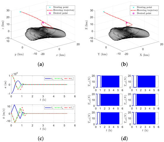
Figure 8 presents the proposed controller’s trajectories and actuation response. Figure 8a,b illustrate the motion in the inertial frame and asteroid-fixed frame , respectively. Figure 8c displays the position and velocity tracking histories, allowing the transfer transient and subsequent hovering regulation to be distinguished. Figure 8d displays the realized six-thruster PWPF commands. The initially larger and more frequent pulses are associated with the transfer maneuver, whereas intermittent actuation is required near the hovering point to compensate environmental accelerations and residual tracking errors. The actual pulse sequence depends on the modulator thresholds, sampling interval, allocation, and command histories; a specific switching frequency or duty-cycle reduction cannot be inferred from these plots alone.
Figure 8.
Inertial hovering with PWPF-modulated multi-thruster on–off actuation using the proposed position-only NFTSMC–FTDO: (a) inertial-frame trajectory; (b) asteroid-fixed-frame trajectory; (c) position and velocity tracking errors; and (d) realized commands of the six on–off thrusters.
Unlike the body-fixed continuous-thrust study, the observer-reconstruction and disturbance-estimation plots are deliberately omitted to avoid repeating the same diagnostic assessment. The inertial case instead evaluates the closed-loop consequences of position-only feedback under pulsed actuation. The position-only observer’s velocity-estimation root-mean-square error for this simulation is m/s. This quantity represents estimation accuracy over the evaluated time history, not the terminal velocity tracking error. It is reported to document the estimation burden during the larger inertial transfer transient; by itself, it does not establish an observer convergence time or a guaranteed disturbance-estimation bound.
Figure 9 compares position- and velocity-error norms, cumulative , and spacecraft mass evolution for the three controllers. The updated indices in Table 5 show that the proposed NFTSMC–FTDO yields a terminal position error of m, versus m for ATC and m for stand-alone NFTSMC. These correspond to reductions of approximately and , respectively. The proposed terminal velocity error is m/s, compared with m/s and m/s, reductions of approximately and . The proposed controller therefore provides the lowest terminal errors of the three methods for the stated PWPF simulation.
Figure 9.
Three-controller comparison for inertial hovering with PWPF-modulated on–off actuation: (a) position-tracking error norms; (b) velocity-tracking error norms; (c) reported cumulative index; and (d) spacecraft mass histories. The comparison includes ATC, NFTSMC, and the proposed position-only NFTSMC–FTDO.
Table 5.
Reported simulation-model performance indices for inertial hovering with PWPF-modulated six-thruster on–off actuation (historical implementation; see validation qualifications in the text).
The proposed method also has the lowest reported cumulative at m/s, compared with m/s for ATC and m/s for NFTSMC, representing reductions of approximately and , respectively. The reported propellant consumption is kg, compared with kg and kg, yielding savings of approximately and . These simulation-model indices indicate improved terminal accuracy and lower modeled propulsion expenditure for the proposed controller. Transient trends and the fidelity of these results to the revised implementation require confirmation against the associated time histories and actuator diagnostics.
The inertial case illustrates conversion of the NFTSMC–FTDO acceleration command into simulated on–off thruster pulses while retaining submeter terminal position accuracy in the recorded numerical run. In contrast to continuous control, the realized on–off acceleration deviates instantaneously from its commanded counterpart; consequently, the numerical results assess the combined effects of observer-based velocity reconstruction, disturbance compensation, thruster allocation, and PWPF realization rather than isolating any one mechanism. An actuator-focused follow-up should quantify per-thruster ignition counts, accumulated on-time, minimum pulse duration, and command-realization mismatch, alongside the reported and model-based propellant consumption. These additional quantities would support a direct evaluation of switching burden and implementation feasibility without duplicating the observer-estimation figures.
Overall, the inertial-hovering study demonstrates a favorable terminal-accuracy–propulsion tradeoff for the proposed position-only NFTSMC–FTDO under the stated PWPF simulation. The result complements the continuous-thrust study by assessing pulsed implementation rather than repeating the observer plots. It remains a scenario-specific numerical comparison; robustness across navigation-noise realizations, modulator parameters, and thruster constraints should be established separately.
5. Conclusions
This study developed and assessed a position-only NFTSMC–FTDO framework for spacecraft hovering near asteroid 433 Eros under uncertain translational dynamics and limited actuation. Its main contributions are:
- Position-only reconstruction: A dynamics-augmented third-order sliding-mode observer reconstructs velocity and lumped acceleration uncertainty from navigation position, a nominal dynamics model, and realized thruster acceleration. The implemented regularization is intended to moderate noise-driven switching and does not inherit an unconditional exact finite-time convergence guarantee.
- Disturbance-compensated finite-time control: Observer estimates provide velocity feedback and acceleration compensation without navigation-velocity measurements. The analysis separates ideal finite-time reaching under restrictive assumptions from conditional practical bounded-error behavior in the regularized, actuator-constrained system.
- Six-thruster assessment: Continuous-thrust and PWPF on–off simulations compare ATC, NFTSMC, and the proposed method. The proposed controller achieves terminal position errors of 0.481 m and 0.509 m, with cumulative of 246.57 m/s and 243.20 m/s, in the body-fixed and inertial studies, respectively. Both cases show lower terminal position errors and cumulative than the selected baselines under the reported simulation conditions.
The results suggest that position-only observer feedback can support accurate hovering with lower modeled control expenditure in the studied scenarios. The tables contain the supplied November 15 indices, but their associated figures must be checked against identical simulation runs; corrected sign-split allocation and PWPF-residual statistics have not been independently validated by those historical indices. Before submitting a final numerical claim for the revised implementation, the full three-controller simulation should be rerun with independent stage-consistent PWPF states and per-thruster mass flow. Additional future work includes robust performance over multiple noise realizations and tighter closed-loop bounds.
Funding
This research received no external funding.
Data Availability Statement
The data supporting the findings of this study were generated through numerical simulations conducted by the author and are available from the corresponding author upon reasonable request.
Conflicts of Interest
The author declares no conflicts of interest. This research was conducted independently and does not represent the official views or positions of Lockheed Martin Space or its affiliates.
References
- Sawai, S.; Scheeres, D.J.; Broschart, S.B. Control of Hovering Spacecraft Using Altimetry. J. Guid. Control Dyn. 2002, 25, 786–795. [Google Scholar] [CrossRef] [Scilit] [PubMed]
- Scheeres, D.J. Orbital Motion in Strongly Perturbed Environments; Springer: Berlin/Heidelberg, Germany, 2012; Chapter 11; pp. 243–254. [Google Scholar] [CrossRef] [Scilit]
- Broschart, S.B.; Scheeres, D.J. Boundness of Spacecraft Hovering Under Dead-Band Control in Time-Invariant Systems. J. Guid. Control Dyn. 2007, 30, 601–610. [Google Scholar] [CrossRef] [Scilit]
- Lee, D.; Sanyal, A.K.; Butcher, E.A.; Scheeres, D.J. Almost Global Asymptotic Tracking Control for Spacecraft Body-Fixed Hovering Over an Asteroid. Aerosp. Sci. Technol. 2014, 38, 105–115. [Google Scholar] [CrossRef] [Scilit]
- Lee, D.; Sanyal, A.K.; Butcher, E.A.; Scheeres, D.J. Adaptive Sliding Mode Control for Spacecraft Body-Fixed Hovering in the Proximity of An Asteroid. Aerosp. Sci. Technol. 2015, 46, 471–483. [Google Scholar] [CrossRef] [Scilit]
- Gui, H.; de Ruiter, A.H.J. Control of Asteroid-Hovering Spacecraft with Disturbance Rejection Using Position-Only Measurements. J. Guid. Control Dyn. 2017, 40, 2401–2416. [Google Scholar] [CrossRef] [Scilit]
- Bhat, S.P.; Bernstein, D.S. Finite-Time Stability of Continuous Autonomous Systems. J. Guid. Control Dyn. 2000, 23, 770–777. [Google Scholar] [CrossRef] [Scilit] [PubMed]
- Lee, D.; Leeghim, H. Reaction wheel fault-tolerant finite-time control for spacecraft attitude tracking without unwinding. Int. J. Robust Nonlinear Control 2020, 30, 3672–3691. [Google Scholar] [CrossRef] [Scilit]
- Levant, A. Robust exact differentiation via sliding mode technique. Automatica 1998, 34, 379–384. [Google Scholar] [CrossRef] [Scilit]
- Levant, A. Higher-order sliding modes, differentiation and output-feedback control. Int. J. Control 2003, 76, 924–941. [Google Scholar] [CrossRef] [Scilit]
- Shtessel, Y.; Edwards, C.; Fridman, L.; Levant, A. Sliding Mode Control and Observation; Birkhauser: Basel, Switzerland, 2014. [Google Scholar] [CrossRef] [Scilit]
- Sun, L.; Song, Y.; Lv, M. Safe Distributed Event-Triggered Control of Uncertain Multiagent Systems Under Conflicting Constraints. IEEE Trans. Syst. Man. Cybern. Syst. 2026. Early access. [Google Scholar] [CrossRef] [Scilit]
- Hu, W.D.; Scheeres, D.J. Numerical Determination of Stability Regions for Orbital Motion in Uniformly Rotating Second Degree and Order Gravity Fields. Planet. Space Sci. 2004, 52, 685–692. [Google Scholar] [CrossRef] [Scilit]
- Scheeres, D.J. Orbit Mechanics about Asteroids and Comets. J. Guid. Control Dyn. 2012, 35, 987–997. [Google Scholar] [CrossRef] [Scilit]
- Du, H.; Li, S.; Qian, C. Finite-Time Attitude Tracking Control of Spacecraft With Application to Attitude Synchronization. IEEE Trans. Autom. Control 2011, 56, 2711–2717. [Google Scholar] [CrossRef] [Scilit]
- Yu, S.; Yu, X. Robust Global Terminal Sliding Mode Control of SISO Nonlinear Uncertain Systems. In Proceedings of the 39th IEEE Conference on Decision and Control, Sydney, Australia, 12–15 December 2000; Volume 3, pp. 2198–2203. [Google Scholar]
- Yu, S.; Yu, X.; Zadeh, B.; Mand, Z. Continuous Finite-Time Control for Robotic Manipulators with Terminal Sliding Mode. Automatica 2005, 31, 1957–1964. [Google Scholar] [CrossRef] [Scilit]
- Moreno, J.A.; Osorio, M. Strict Lyapunov Functions for the Super-Twisting Algorithm. IEEE Trans. Autom. Control 2012, 57, 1035–1040. [Google Scholar] [CrossRef] [Scilit]
- Wie, B. Space Vehicle Dynamics and Control, 2nd ed.; AIAA Education Series; AIAA: Reston, VA, USA, 1998; pp. 452–455. [Google Scholar]
- Scheeres, D.J.; Williams, B.G.; Miller, J.K. Evaluation of the Dynamics: Environment of an Asteroid: Applications to 433 Eros. J. Guid. Control Dyn. 2000, 23, 466–475. [Google Scholar] [CrossRef] [Scilit] [PubMed]
- Hui, L.; Li, J.; Baoyin, H. Sliding Mode Control for Low-Thrust Earth-Orbiting Spacecraft Formation Maneuvering. Aerosp. Sci. Technol. 2006, 10, 636–643. [Google Scholar] [CrossRef] [Scilit]

Disclaimer/Publisher’s Note: The statements, opinions and data contained in all publications are solely those of the individual author(s) and contributor(s) and not of MDPI and/or the editor(s). MDPI and/or the editor(s) disclaim responsibility for any injury to people or property resulting from any ideas, methods, instructions or products referred to in the content. |
© 2026 by the author. Licensee MDPI, Basel, Switzerland. This article is an open access article distributed under the terms and conditions of the Creative Commons Attribution (CC BY) license.