


Abstract
In the context of Industry 5.0, human–robot collaboration increasingly demands intuitive, safe, and sensorless interaction for tasks such as hand-guided teaching and concurrent manipulation. However, conventional admittance control systems are prone to instability due to abrupt changes in human arm stiffness and their reliance on accurate dynamic models. To address these challenges, this paper proposes a sensorless external force estimation and variable admittance control method that models robot dynamic uncertainties and interaction forces as normally distributed stochastic quantities. An improved particle swarm optimization algorithm is introduced to calibrate the variance parameters, enhancing estimation accuracy and robustness. Furthermore, an energy-based variable admittance control strategy is developed, which preserves system passivity by adaptively adjusting inertia and damping gains based on real-time energy variations. The proposed method was validated on a redundant robot platform. Experimental results show that the external force and torque estimation errors remain below 3 N and 3 N.m, respectively, with lower detection delays and errors than those of a first-order generalized momentum observer in collision detection. Variable admittance experiments demonstrate that the system maintains passivity and stable interaction even under sudden arm stiffness changes. The approach is well-suited for industrial applications requiring safe, sensorless, and compliant human–robot collaboration.
1. Introduction
The human–robot interaction compliance control technology, which combines the precise mechanical performance of robots with the logical thinking and adaptability of the human brain, is one of the research hotspots in the field of robotics [1,2,3]. Human–robot interaction is often achieved by sensing human motion intentions through force sensors, utilizing the dynamic relationship between force and position to realize compliance control objectives. However, the introduction of force sensors directly reduces the stiffness of the robot’s end-effector, narrows the detection force bandwidth, and increases the complexity of system integration.
In the context of Industry 5.0, human–robot collaboration is expected to be flexible, intuitive, and safe, especially in tasks such as hand-guided teaching, collaborative assembly, and shared workspace operations. In these scenarios, the ability to estimate external forces without force sensors and to maintain stable interaction under varying human arm stiffness is essential for practical deployment. However, most existing methods either rely on accurate dynamic models or lack passivity guarantees during abrupt stiffness changes, limiting their applicability in industrial settings. Recent advances in soft robotics have further enriched human–robot collaboration paradigms. For instance, Cho et al. [4] developed a bidirectional double-spring pneumatic artificial muscle with inductive self-sensing capability, enabling intrinsic compliance and force perception without external sensors. Similarly, liu et al. [5] proposed a fully flexible wearable pouch pneumatic artificial muscle based on asymmetric expansion, demonstrating safe and adaptive physical interaction in exoskeleton applications. These developments underscore the growing importance of sensorless force estimation and compliance control in collaborative scenarios.
To avoid the use of force sensors, Zhao et al. [6] proposed an external torque observer based on generalized momentum deviation to achieve collision detection by observing the deviation between the robot’s theoretical momentum and actual momentum. Building on this, CHIEN et al. [7], FU et al. [8], and Jia Qingxuan et al. [9] expanded the application of the generalized momentum method to enable collaborative human–robot interaction operations. On the other hand, built-in sensor information, such as joint motor torque and joint angles, can also be used to estimate the interaction force of the robot [10]. YUAN et al. [11] proposed a method for estimating the robot end-effector contact force based on the motor output torque and a redundant robot pseudo-inverse model to achieve force tracking control. However, the aforementioned external force estimation methods require an accurate robot dynamic model, which is difficult to obtain in practice. Therefore, Li Yang et al. [12] proposed a recursive parameter identification method based on prior dynamic knowledge to implement force-sensor-free full-arm compliance control. KOMMURI et al. [13] adopted an online external force torque estimation method based on a high-order sliding mode observer to compensate for generalized momentum dynamic estimation errors. XIAO et al. [14] designed a fast load parameter identification algorithm before estimating the human–robot interaction force, which compensates for the static and dynamic forces generated by the load and decouples the load force from the human–robot interaction force.
Human–robot interaction requires the robot to comply with the interaction force exerted by the operator in order to maintain system safety and stability. Among various approaches, admittance control is widely used in human–robot interaction control research [15]. Tang Yucun et al. [16] combined the principles of admittance control and virtual fixture to propose a safety strategy to address safety issues caused by improper operations and the complexity of tasks in shared human–robot environments. Caballero-Mora et al. [17] proposed a force controller based on admittance, employing an active disturbance rejection control method, which enables robot force control without the need for force sensors. HE et al. [18] established admittance control for the Baxter robot in a constrained environment, using the interaction force output to avoid collisions with the environment based on reference position information. KARAMI et al. [19] implemented human–robot collaborative compliance control with priority constraints in the robot’s null space, without requiring joint torque sensors. However, under uncertain robot dynamics and time-varying environments, fixed compliance control gain parameters cannot guarantee optimal human–robot interaction performance, necessitating the development of adaptive compliance control strategies. XU et al. [20] proposed an adaptive admittance control algorithm based on recursive neural networks, considering the impact of uncertainties in the human–robot interaction dynamic model and robot dynamic parameters on admittance control. YU et al. [21] applied Bayesian algorithms to adaptively adjust compliance control gain parameters based on prior human hand stiffness knowledge, achieving the robot’s target impedance model to complete collaborative human–robot tasks.
The aforementioned research works have the following shortcomings: the external force estimation methods mentioned above do not account for sudden changes in the human arm’s dynamic characteristics in human–robot interaction, making it impossible to correctly estimate the interaction force. To achieve force-sensor-free human–robot interaction compliance control, the adaptive compliance control strategies mentioned above are not suitable for interaction scenarios where the human arm’s dynamic characteristics change, resulting in the system’s inability to maintain stability. Due to the superior flexibility of redundant robots [22], this paper addresses the above issues by focusing on redundant robots as the research subject and proposes a new variance-calibration-based external force estimation method for low-speed human–robot interaction. Additionally, from the perspective of passivity [23], the paper realizes adaptive admittance compliance control for human–robot interaction. It is worth noting that the conventional human–robot interaction hand-guided teaching task at the robot end-effector inherently operates in the low-velocity regime. Under such quasi-static conditions, the passivity constraint becomes the primary concern for stable physical interaction. The proposed framework is therefore well-aligned with the intrinsic characteristics of this application scenario.
2. System Methods
2.1. Robot Admittance Dynamic Model
To achieve compliant human–robot interaction without force sensors, it is essential first to establish the robot’s dynamic model, which describes the relationship between the robot’s motion and the driving forces. In this section, based on the dynamic equations in both joint space and operational space, an admittance control model suitable for low-speed human–robot interaction is derived, providing a theoretical foundation for subsequent external force estimation and compliant control.
The dynamic equations of motion for an n-degree-of-freedom robot joint space are established as follows:
In Equation (1), , , and represent the joint angles, angular velocities, and angular accelerations of the robot, respectively; denotes the positive definite inertia matrix; corresponds to the Coriolis and centrifugal forces; represents the gravitational force of the robot; refers to the joint friction torque, where and are the Coulomb and viscous coefficients, respectively; indicates the joint driving torque, with being the reduction ratio and the motor torque; stands for the external torque, where is the robot Jacobian matrix and represents the human–robot interaction force, with denoting its estimated value.
The dynamic equation of the robot in the operational space is obtained by transforming Equation (1) as follows:
In Equation (2), ; ; ; ; ; ; represents the robot end-effector’s pose.
In variable admittance compliance control, the relationship between the human–robot interaction force and the robot end-effector’s pose is described as follows:
In Equation (3), and are the compliance control inertia gain and damping gain at time , respectively, and both are bounded semi-positive definite matrices.
Substituting Equation (3) into Equation (2), the robot end-effector compliance control driving force is obtained as follows:
Since depends on the robot configuration, and a time-varying may degrade the compliant performance, a constant inertia matrix is adopted instead of its time-varying counterpart .
In human–robot interaction, when controlling the robot end-effector to comply with the variation of at a lower motion speed, Equation (4) is re-described as:
From Equation (5), it can be seen that, relative to zero-force control [24], is amplified or reduced by a factor of , and under the condition that and are known, is a fixed constant. Therefore, the estimated external force at low speed is:
Due to the existence of redundant degrees of freedom, the robot can also perform tasks within the null space to avoid joint angle limits. Therefore, the control torque for the redundant robot joints can be expressed as:
In Equation (8), , where represents the torque of the i-th joint for avoiding joint angle limits [25], which is defined as:
Here, is the maximum repulsive torque for avoiding joint angle limits; and represent the positive and negative limits of , respectively; and is the joint angle limit threshold. When and , the joint experiences a torque in the opposite direction of motion, which pushes the robot joint away from the angle limit.
As for the joint angle limit threshold , a too small value activates only very close to the joint limit, preserving mid-range compliance but risking hard impacts at high speed; a too large value activates far from the limit, ensuring smooth deceleration and safety but reducing the effective working range and distorting impedance. By the same token, as for the maximum repulsive torque , a too small value provides insufficient limit stiffness, losing protection while maintaining compliance transparency; a too large value gives high stiffness that strongly pushes the joint away from the joint angle limit, offering good protection but causing abrupt contact force changes, large tracking errors, and possible oscillatory instability due to the distorted compliance characteristics near the limit. According to theoretical constraints and engineering practice [26,27], is set at 5–10% of the joint travel range, and is set at 10–30% of the joint rated torque.
Theorem 1.
Adding and into the robot dynamics formula ensures that each joint of the robot moves within its joint angle limits successfully, while not affecting the passivity of the robot manipulator system.
Proof.
Write Equation (9) in vector form:
In the equation, is the virtual potential energy for joint limit avoidance and is continuously differentiable. Obviously, is a purely conservative force, depending only on position, containing no velocity terms, no non-conservative dissipation, and no energy injection terms.
The system dynamics after adding the limiting torque is:
In the equation, is the main task compliance.
Substituting into Equation (1).
Define an extended energy function:
Taking the time derivative yields:
Substituting using the dynamics:
Substituting and using the skew-symmetric property , we obtain:
But ; therefore:
Thus, we obtain the extremely critical result:
Therefore, introducing and into a stable human–robot interaction system does not affect the passivity of the system, and the system remains stable. □
2.2. Variance Calibration External Force Estimation Model
2.2.1. External Force Estimation Model
Since external forces cannot be directly measured in sensorless scenarios, they must be estimated indirectly using the robot’s built-in sensors. In this section, based on the robot dynamic equations, both the model errors and the interaction forces are modeled as stochastic quantities. The strategy of transforming robot dynamic uncertainties and interaction force into a normal distribution has been applied in the field of human–robot interaction. Olsen et al. [28] demonstrated that torque prediction residuals from maximum likelihood identification exhibit approximately Gaussian statistics on an industrial manipulator. Wei et al. [29] further adopted a Gaussian framework to handle imperfect dynamic models in sensorless contact force estimation, validating this approach in physical human–robot interaction scenarios. A variance-based external force estimation model is then developed to achieve effective estimation of human–robot interaction forces.
In low-speed human–robot interaction, the external force acting on the robot, which needs to be estimated, can be expressed as:
In Equation (19), and are the feedforward compensation terms for and , respectively, and is the residual effective force that includes , defined as:
Due to the existence of errors in the robot’s dynamic model, the feedforward compensation terms in Equation (19) contain a compensation error .
In Equation (21), and .
Combining Equations (4), (19) and (21), the specific expression of the external force estimation model can be obtained.
It can be seen from the equation that , , and are linearly related. If , then .
Due to the complexity of the robot model error and the inconsistency of the force applied by the human hand, let and follow a normal distribution, with expectations and , variances and , and covariance .
Let the error between and be denoted as . A calibration matrix is sought to formulate the constrained objective function for external force estimation.
Then, is redefined as:
Its is expressed as:
Differentiating Equation (26) yields:
Let , then the optimal is:
Therefore, based on Equations (24) and (28), we obtain a variance-based calibration method for robot external force estimation. The estimation of the human–robot interaction force can be described as:
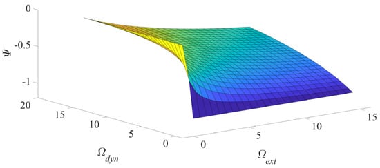
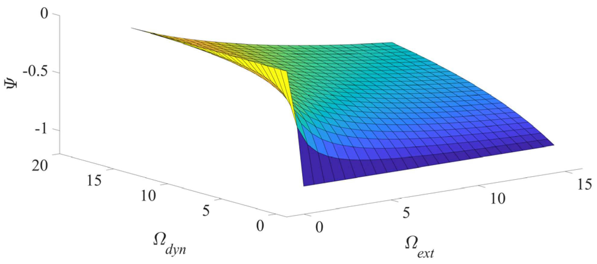
From Figure 1, it can be observed that is relatively sensitive to . As the value of element increases, the calibration matrix gradually loses its effectiveness in estimating . When is a constant value, changes slowly relative to , showing weak sensitivity. Furthermore, when , the robot’s feedforward control can accurately compensate for the state variables, and thus , .
Figure 1.
Variance relationship of the external force estimation model.
2.2.2. Model Bias Modeling
In practical applications, the feedforward compensation of the robot dynamic model often suffers from systematic deviations, which directly affect the accuracy of external force estimation. This subsection aims to analyze the composition and statistical characteristics of the external force estimation error when such model deviations are non-negligible. By mathematically modeling the deviation force, its expected impact on the estimation results is analyzed, providing a theoretical basis for bias compensation to further optimize the estimation model.
Therefore, when , it follows from Equation (22) that:
Thus, cannot be approximately equal to .
Let be the robot model bias force, , and ; then, the external force estimation error is:
The expected value of related to model bias can be expressed as:
If and , then , and the expected value of the external force estimation is equal to the expected value of the model bias force .
2.2.3. Variance Calibration
To obtain the key variance parameters in the model established in Section 2.2.1, an improved particle swarm optimization algorithm is introduced in this section for parameter calibration. Compared with standard PSO, the improved algorithm incorporates three key modifications. First, a cubic chaotic map is employed for population initialization to enhance diversity and global search capability. Second, the inertia weight factor is adaptively adjusted according to the iteration state using an exponential decay scheme, balancing exploration and exploitation during convergence. Third, a premature convergence detection mechanism is introduced, whereby chaotic perturbation is applied to particles when stagnation is identified, enabling the swarm to escape local optima. These enhancements collectively improve the algorithm’s robustness in calibrating the variance parameters and .
By collecting data from the robot’s built-in sensors and external force sensors under the zero-force control mode, an optimization function is constructed to minimize the error between the estimated force and the actual force. Meanwhile, to mitigate the directional influence of model deviations on the estimation results, singular value decomposition is employed to impose an isotropy constraint. The objective of this section is to determine the optimal error variance matrix through offline optimization, thereby enabling the external force estimation model to achieve higher accuracy and robustness in practical applications.
Establish a robot low-speed task-space zero-force control model as:
In Equation (33), represents the human–robot interaction force detected by the end-effector force sensor.
Real-time acquisition of , , , and is performed, with offline optimization of and , such that at each sampling moment, the norm of the difference between the estimated external force and based on Equation (29) is minimized, i.e.,
In addition, the robot model bias force expectation may exist; however, in practice, is difficult to obtain, so it is not possible to optimize the external force estimation error expectation based on Equation (32).
Since singular value decomposition (SVD) of a matrix can characterize the degree of characteristic variation between a matrix and a vector, define , and , where , and are the left singular vector matrix, singular value matrix, and right singular vector matrix of , respectively. Here, corresponds to the characteristic variation direction associated with the largest singular value . If the magnitude of is larger, the corresponding output task-space direction of is more susceptible to the influence of . Therefore, it is necessary to limit of and optimize under the influence of to maintain its optimal isotropy, i.e.,
Combining Equations (34) and (35), the optimization objective is set as:
In Equation (36), , , where and are the optimization weight values, with and .
The proposed external force estimation method relies on feedforward compensation using the robot dynamic model. Although the variance of the model error is optimally calibrated via optimization method, factors such as nonlinear friction and unmodeled dynamics cannot be fully compensated, leading to a response lag in the estimated force. Additionally, low-pass filtering applied to built-in sensor signals introduces phase lag, affecting real-time performance. The variance calibration is performed offline, yielding an optimal solution in a statistical sense; however, it cannot eliminate instantaneous response delays under dynamically changing interaction forces. Therefore, in order to reduce latency in real-time tasks, a Kalman filter delay compensation algorithm is introduced for improvement based on the proposed offline variance calibration [30,31], as shown in Algorithm 1. The principle of its pseudocode is shown as follows:
| Algorithm 1: Kalman Filter with Fixed Time-Delay Compensation (Iteration Results) |
| Input: Delayed measurement // Measurement with total delay System delay steps // Number of discrete steps corresponding to the delay State transition matrix // System matrix Observation matrix // Observation matrix Process noise covariance // Process noise covariance Measurement noise covariance // Measurement noise covariance Output: Predicted state // Future predicted force after compensating for delay Initialization: = initial_state // Initial state; = initial_covariance // Initial covariance Main Loop (for each time step ): // 1. Standard Kalman time update (single-step prediction) // 2. Standard Kalman measurement update (correction) // 3. Core: Fixed t-step state extrapolation (key step for delay compensation) // 4. Output the predicted value to replace the delayed signal for real-time tasks Return |
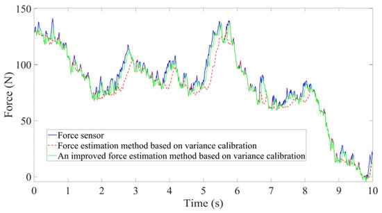
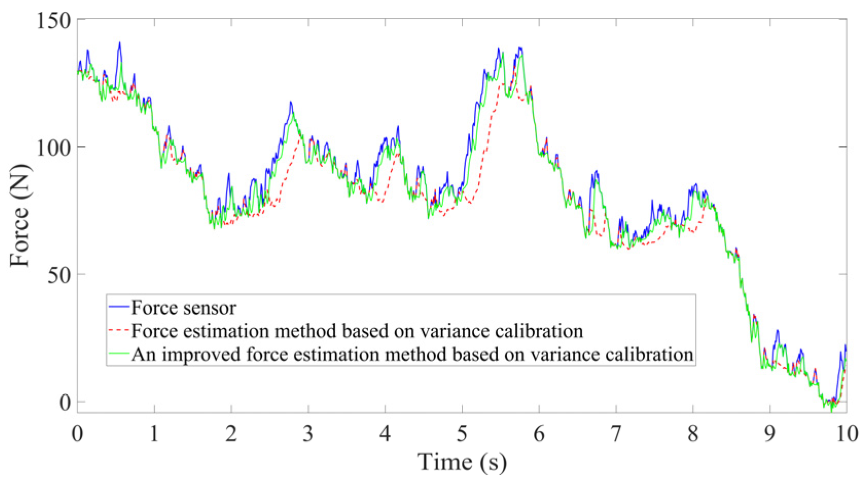
As shown in Figure 2, the force information predicted by the proposed method lags behind the force information collected by the force sensor by 15 sampling steps. However, after adding the real-time Kalman filter delay compensation algorithm to this method, the predicted force information from the improved variance calibration force estimation method is much closer to the force information collected by the force sensor, with a delay compensation of 66.67%, which can meet the real-time requirements of low-speed human–robot interaction.
Figure 2.
The force information collected by a force sensor and two external force estimation methods.
2.3. Variable Admittance Compliance Control
2.3.1. Variable Admittance Control
In traditional variable admittance control, if the inertia gain and damping gain in the admittance controller are set too high, the robot system becomes insensitive to the perceived force , making it difficult to achieve compliant motion in response to human-applied forces. In such cases, the human operator must exert significant effort to move the robot. Conversely, if and are set too low, the human can easily move the robot end-effector, but the system struggles with small-displacement motions, preventing precise positioning of the robot end-effector. Therefore, applying variable admittance control in robot compliance control presents a practical solution.
In traditional human–robot interaction admittance control, the inertia gain and damping gain are typically set as constant matrices. The control law can be expressed as:
In Equation (37), and are the constant inertia and damping gain matrices, respectively; is the reference trajectory output by the admittance controller; and is the perceived human–robot interaction force.
However, in practical human–robot collaboration, the passivity condition of this fixed-parameter control approach is difficult to guarantee.
According to passivity theory, the necessary and sufficient condition for the admittance control system to remain stable is that its input and output satisfy:
where is the initial energy stored in the system. When sudden changes in human arm stiffness lead to rapid variations in the interaction force, fixed-gain control may result in:
That is, the stored energy in the system exhibits negative growth, thereby violating the passivity condition. Under such circumstances, the dynamic response of the system may develop divergent oscillations:
In severe cases, this compromises the safety of human–robot interaction.
2.3.2. Passivity Condition for Variable Admittance
From the analysis of the limitations of traditional admittance control, it is evident that, in variable admittance compliant control, the dynamic adjustment of inertia and damping parameters may compromise the passivity of the system, leading to instability during human–robot interaction. This section aims to derive the mathematical conditions for maintaining the passivity of the variable admittance control system from an energy perspective. By introducing an energy storage function and a switching factor, the energy flow characteristics of the system under different operating conditions are analyzed, providing a theoretical boundary for stability assurance in the subsequent adaptive control strategy.
In variable admittance compliance control, is a passivity prerequisite to ensure the stable and safe operation of the human–robot interaction system [32]. To maintain system passivity, an energy-based variable admittance compliance control strategy is proposed. The variable admittance compliance control system along the operation space coordinate axis direction in Equation (4) is redefined as:
In Equation (41), represents the estimated human–robot interaction force along the i-direction; represents the energy dissipated by the damping gain variation along the i-direction; represents the energy consumed or injected by the inertia gain variation along the i-direction; represents the state variable in the i-direction; and represents the energy stored in the system along the i-direction at time t, where , and and are the upper and lower bounds of the energy stored in the system along the i-direction, and and are the energy switching factors for damping gain and inertia gain, respectively, defined as:
From the above equation, it can be concluded that indicates energy injection into the system in the direction of , while indicates that the change in requires energy consumption from the system. When , will close the energy injection due to gain variation into the system. When , .
Theorem 2.
Suppose that during the human–robot interaction process at , the system experiences instability. Under the condition of input and output , the variable admittance compliance control system based on Equation (43) always maintains passivity. Within the time , the system will be stabilized again. Here, , , and , are the minimum and maximum robot velocities along the i-direction.
Proof.
Let the energy function at time t along the i-direction be defined as:
In Equation (43), .
Taking the first-order derivative with respect to time t yields:
Since , Equation (44) can be rewritten as:
If , then . If , then and . Therefore, Equation (48) is redefined as:
Clearly, Equation (41) transforms the admittance compliant control system, which can maintain passivity under unstable conditions and allowing the system to tend toward stability.
However, in the above proof, the system requires sufficient energy supply to accommodate changes in inertia gain, i.e., . At , the stored energy in the i-direction of the system is represented as:
Since , and only when , the change in can consume energy from the system, while satisfying . Therefore, Equation (47) must satisfy the following constraint:
That is, .
Since is bounded and semi-positive definite, at , has a bounded maximum eigenvalue . Under the condition that is bounded, the above equation can be expressed as:
Therefore, based on Equations (48) and (49), the inertia gain adjustment rate in the i-direction, , ensures that the system has enough energy to achieve inertia gain variation without violating the system’s passivity, thereby guaranteeing the system’s stability, which can be expressed as:
□
2.3.3. Parameter Adaptive Adjustment
To achieve a dynamic balance between compliance and stability during human–robot interaction, this section designs a parameter adaptive adjustment strategy based on interaction state perception. When sudden changes in human arm stiffness induce system oscillations, traditional fixed-parameter admittance control struggles to maintain stability. To address this issue, this section proposes an adaptive mechanism based on oscillation determination indicators, which enables dynamic adjustment of inertia and damping gains while preserving passivity constraints. This ensures that the robot can both conform to the human’s motion intentions and rapidly suppress instabilities caused by stiffness mutations.
In the human–machine interaction process, based on the interaction force and the current velocity , the parameters and are adaptively adjusted to maintain operational comfort. When fine displacement precision or deceleration is required for stopping, and should remain large. However, when it is necessary to accelerate in response to the interaction force, and should decrease. However, when the stiffness of the human hand or arm suddenly increases, the interaction force cannot be accurately predicted based on Equation (29), which may lead to oscillation and instability at the robot end. In such cases, and cannot be adaptively adjusted.
This paper designs an oscillation determination indicator for the robot end-effector, which is defined as:
In Equation (51), is the sampling time, and and are the stiffness values in the i-direction and the nominal stiffness value, respectively.
When , the robot can accurately track the output trajectory of the variable admittance control. and are adaptively adjusted to maintain a constant inertia-damping ratio under the influence of , which can be expressed as:
In Equation (52), is the adjustment weight for the damping gain in the i-direction; and and are the initial values of the admittance inertia gain and damping gain, respectively.
When , the robot deviates from the trajectory , and oscillation occurs. Without violating the system’s passivity condition, is adaptively adjusted based on Equation (50) to allow the system to recover to a stable operating state within time , that is,
From the equation, it can be seen that a larger will lead to a larger to restore system stability. However, a larger requires a larger to achieve compliant control. Therefore, obtained from Equation (50) needs to be limited. At the same time, in order to achieve continuous variation of and maintain the comfort of human–robot interaction, Equation (54) is modified as follows:
In Equation (55), is the maximum adjustment value of the inertia gain in the i-direction; is the adjustment weight of the inertia gain in the i-direction.
Similarly, the damping gain is adaptively adjusted based on the principle of maintaining a constant inertia-damping ratio, which can be expressed as:
3. Results
To validate the effectiveness of the proposed improved variance-calibrated external force estimation method, this section designs data acquisition and parameter optimization experiments under zero-force control. First, the setup of the experimental platform, sensor configuration, and parameter settings of the improved particle swarm optimization algorithm are introduced. Subsequently, through collision detection experiments and by comparing the optimized estimated force with actual force sensor measurements, the accuracy, latency characteristics, and error distribution of the proposed method in external force estimation are analyzed, thereby verifying its feasibility in sensorless human–robot interaction.
3.1. Robot Experimental Platform Setup
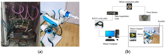
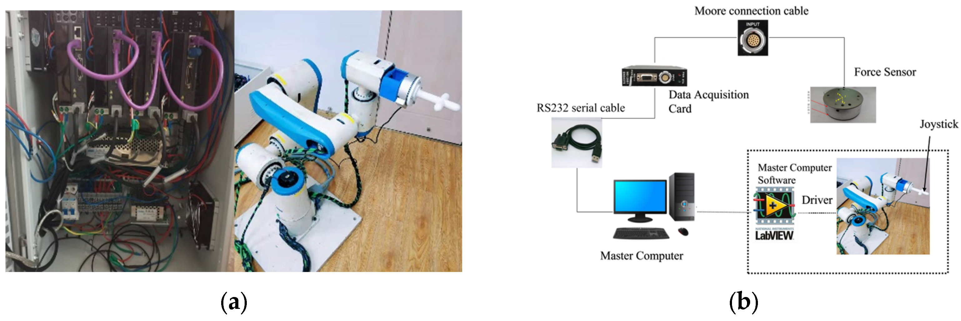
A redundant robotic system employing EtherCAT communication was constructed for direct teaching applications, as illustrated in Figure 3. To evaluate the proposed friction-compensated torque estimation approach, the experimental configuration incorporated a control cabinet, an M4314A force sensor, and an M8128 data acquisition card. Data acquisition, real-time control, and algorithm implementation were performed using LabVIEW 2025 (National Instruments, Austin, TX, USA). Offline data processing, algorithm validation, and figure generation were conducted using MATLAB 2025 (The MathWorks, Inc., Natick, MA, USA). All other algorithms were self-developed within these software environments.
Figure 3.
Experimental platform: (a) Robot body and control cabinet; (b) experimental validation platform.
The experimental platform is designed to emulate typical industrial human–robot collaboration scenarios, including hand-guided teaching, where an operator physically guides the robot end-effector to define task trajectories, and concurrent manipulation, where the robot shares workspace with human operators during assembly or handling operations. These scenarios demand reliable external force estimation and stable admittance control under varying operator arm stiffness.
3.2. External Force Estimation Experiment
Due to the improved particle swarm algorithm’s fast convergence speed and its ability to escape from local optima [33], the experiment collects information from the robot’s built-in sensors, including joint angle , joint angular velocity , joint torque , and external force sensor data , based on the zero-force control experiment in Section 2.2.2. Under the optimization objective function in Equation (36), the improved particle swarm algorithm is used to obtain the optimal variances and in the external force estimation method proposed in this paper.
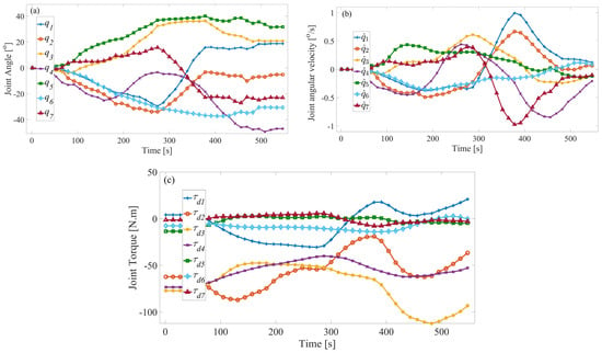
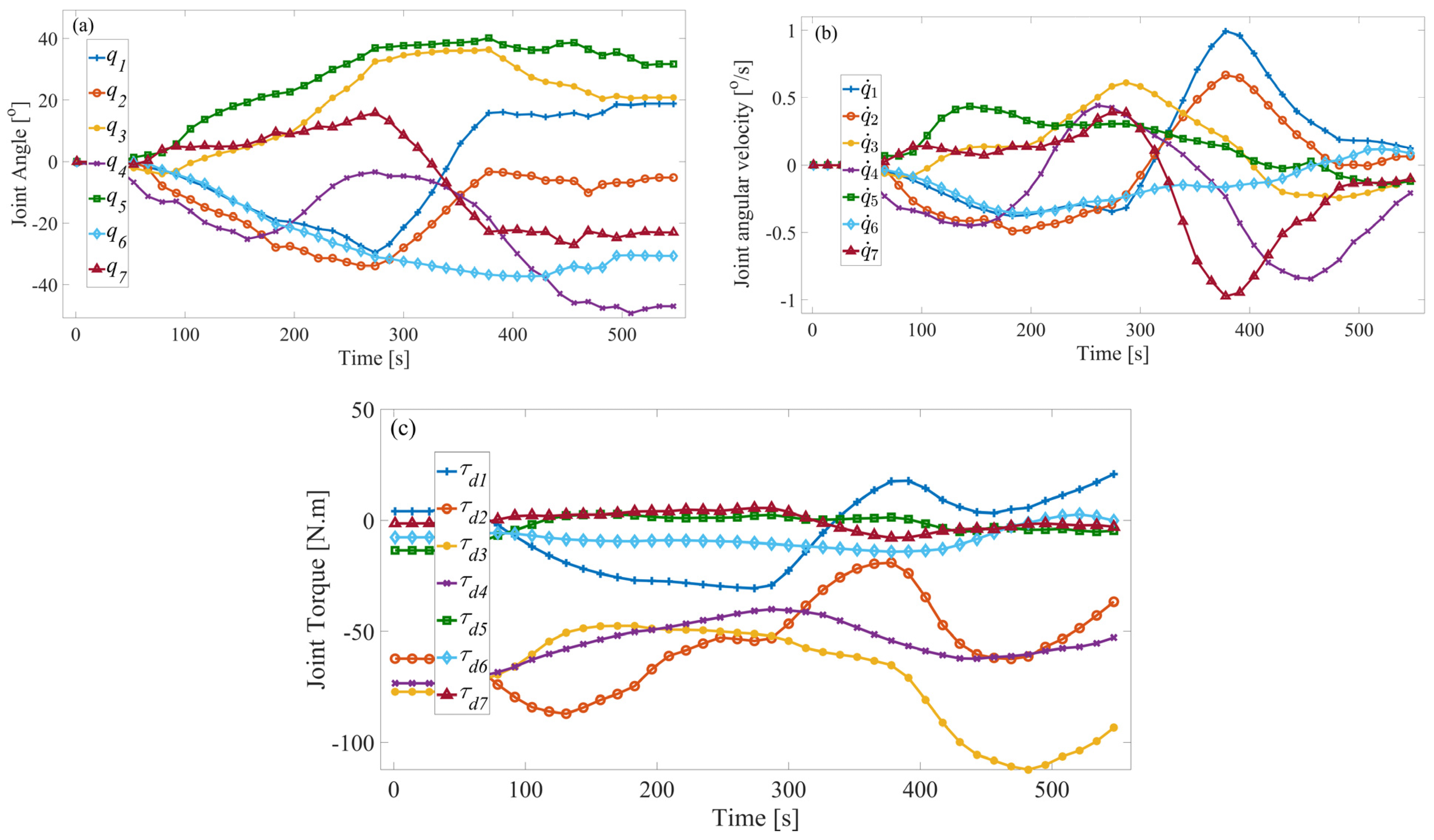
With the external force sensor installed, the joint information from the robot’s built-in sensors and the force information from the external force sensor, as shown in Figure 4 and Figure 5, are acquired.
Figure 4.
Joint information acquired from the built-in sensors: (a) angle, (b) velocity, and (c) torque.
Figure 5.
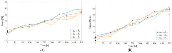
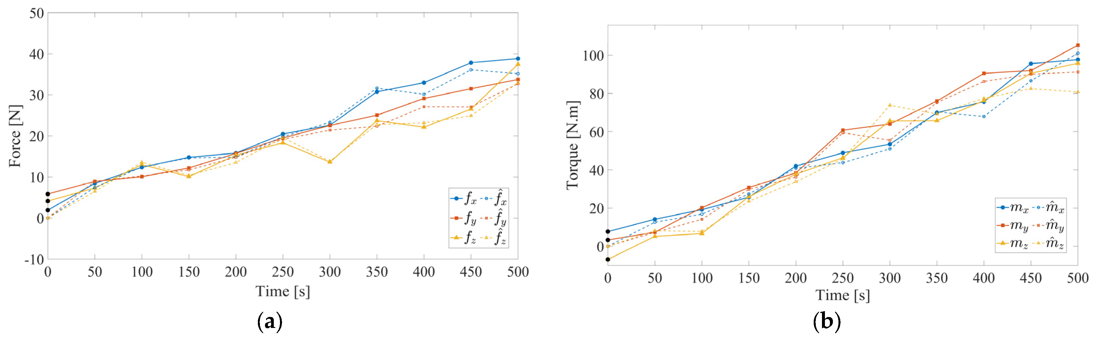
Experimental results of external force estimation: (a) Forces detected by the force sensor and estimated by the proposed method; (b) moments detected by the force sensor and estimated by the proposed method.
Additionally, the parameters for the improved particle swarm algorithm are set as follows:
The swarm size is , the number of iterations is , the maximum inertia weight is , the minimum inertia weight is , the fitness threshold is , the number of perturbation particles is , the particle , , , and the particle dimension search range is and .
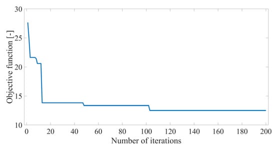
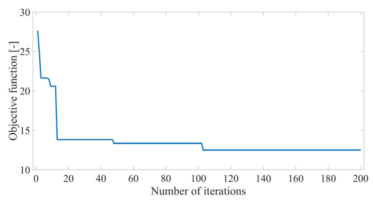
The estimated force information is obtained based on the improved variance calibration method. Substituting the information from Figure 4 and Figure 5 into the improved particle swarm optimization algorithm, as shown in Figure 6, the algorithm begins to converge to the global optimal value of 12.495 starting from the 102nd iteration. At this point, the optimal values of the matrix elements and are shown in Table 1.
Figure 6.
Optimized change curve of objective function.
Table 1.
Algorithm iteration optimization results.
Substituting the optimized and into Equation (30), the estimated external force information using the improved variance calibration method is obtained, as shown in Figure 5. From the figure, it can be seen that the estimated external force in this paper exhibits a delay relative to the force detected by the sensor. The delay rate of the external force estimation along the x-axis is the lowest, with a delay rate of 5.28% of the sampling time, while along the z-axis, the delay rate is the highest, at 10.34%. Since the speed of human–machine interaction is low, the delay rate does not affect the implementation of the human–machine interaction function.
Although Equation (36) accounts for the influence of model deviations on external force estimation during the optimization process, the physical model deviations of the robot still have a significant impact on the estimation results in practice, as shown in Table 2. It can be observed from the table that, at the same sampling instant, the maximum and minimum errors of the estimated force and torque relative to the external force sensor measurements are smallest along the x-axis, both below 3 [N] and 3 [N.m]. In contrast, along the y- and z-axes, the maximum and minimum errors exceed 3 [N] and 3 [N.m]. Nevertheless, the trend of the estimated external force is consistent with that measured by the force sensor. Therefore, even without an external force sensor, the external force estimation method proposed in this paper can still effectively estimate the forces acting on the robot end-effector, meeting the expected requirements and enabling human–robot interaction.
Table 2.
Comparison between the external force applied by the hand detected by the force sensor and the external force estimated by the method proposed in this paper.
3.3. Collision Detection Experiments
To assess the performance of the presented approach, collision detection tests were carried out, benchmarking it against the first-order generalized momentum observer method. Throughout the testing process, joint torque control mode was activated, with data acquisition conducted at a sampling rate of 400 Hz. Keeping all experimental conditions identical, each configuration underwent 100 repeated trials. The manipulator was guided by hand from its home position to a predetermined angular configuration. To obtain statistically robust outcomes, the recorded data were averaged across all repetitions.
The generalized momentum of the robot system is defined as:
The robot dynamic model possesses the following properties:
Substituting Equations (1) and (58) into the time derivative of the generalized momentum yields:
Defining the observed value of the momentum derivative, the above equation becomes:
Substituting Equations (59) and (60) into the time derivative of Equation (61) yields:
Applying the Laplace transform to the above equation and considering steady-state conditions, can be interpreted as the observed external torque.
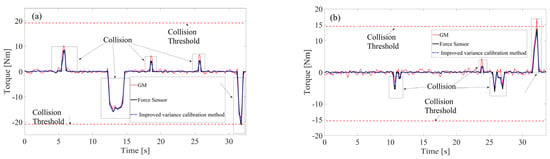
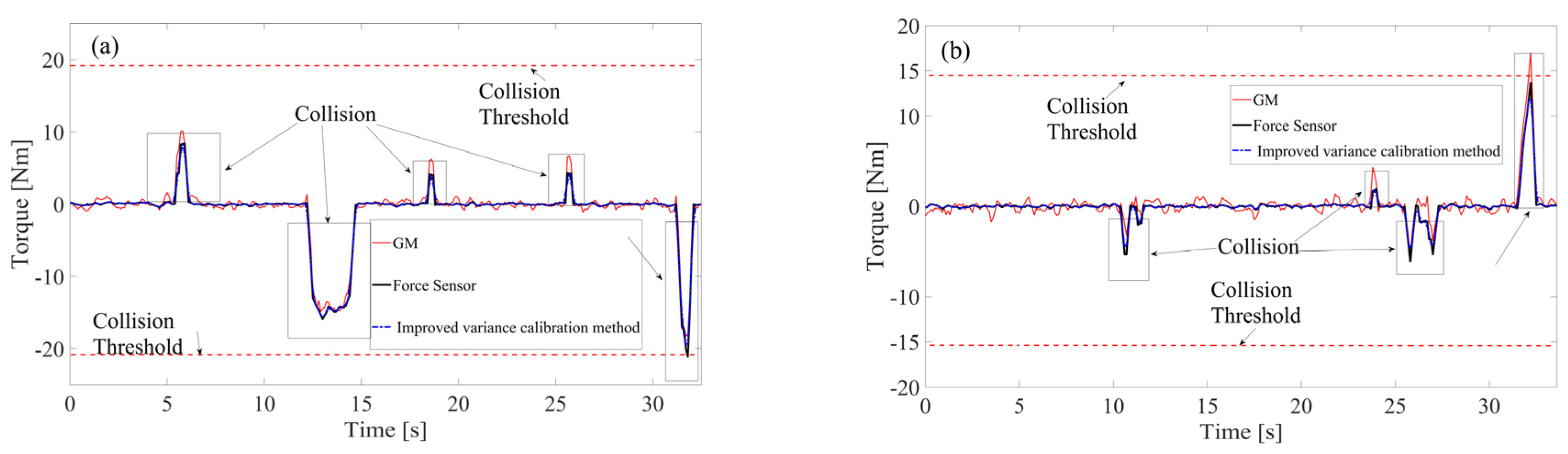
By modeling the first-order generalized momentum observer and comparing it with the proposed method in collision detection, as shown in Figure 7, the following results are obtained.
Figure 7.
Collision detection along the (a) x-axis and (b) y-axis.
To validate the superior performance of the proposed force estimation method in collision detection, this study employs the following quantitative metrics for evaluation: detection delay (DD), peak error (PE), RMSE, and MAE, as shown in Table 3. Among them, the formula for detection delay is given by , where is the moment when the estimated value first exceeds the threshold, and is the moment when the sensor signal first exceeds the threshold.
Table 3.
Performance evaluation of collision algorithms based on key metrics.
The specific formulas for RMSE and MAE are given as follows:
In Equation (64), N denotes the total number of samples, and sensor τ represents the external torque measured by the six-axis force sensor.
As shown in Figure 7 the collision interval is determined based on the external torque reference obtained from the force sensor. The boxed areas in the figure indicate the moments when collisions occur, while the remaining portions correspond to motion periods without collision. Collision detection performance is evaluated using key metrics summarized in Table 3, including detection delay, peak error, and the root mean square error (RMSE)/mean absolute error (MAE) within the collision interval relative to the force sensor reference. As presented in Table 3, among the compared methods, the proposed method achieves the smallest detection delay, peak error, and the lowest RMSE/MAE in both the x- and y-directions, demonstrating faster detection speed and higher agreement with the true values.
3.4. Variable Admittance Compliant Control Experiment
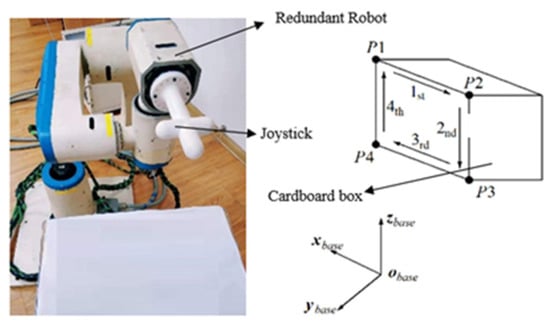
This section verifies the effectiveness of the proposed external force estimation method in human–robot interaction compliant control applications. The experiment is implemented based on the offline optimized and from Table 1. Under the proposed variable admittance compliant control system, the robot end-effector moves around a cardboard box along the estimated -direction, following the trajectory , as shown in Figure 8. This trajectory is designed to represent a typical industrial hand-guiding task: simulates the robot approaching a workpiece under operator guidance; corresponds to a collaborative assembly or handling operation; represents the operator moving the robot to a tool-change position; and involves increased human arm stiffness to simulate scenarios such as sudden operator resistance, tool engagement, or transition to a high-precision operation. During the movement, the operator intentionally increases arm stiffness to evaluate the system’s response to abrupt interaction force variations.
Figure 8.
Variable admittance compliance control experimental device and reference trajectory for robot motion.
Set some main parameters as follows to achieve variable admittance compliance control in the x-, y-, z-axis directions, respectively.
, , , , , At ,, , .
Threshold is determined using a statistical calibration method based on multiple sets of tests under normal operating conditions [34,35], , following the steps below:
- Collect the end-effector force and position data of the robot under stable, vibration-free operating conditions.
- Compute the full-segment vibration stiffness sequence using Equation (51).
- Take the 95th percentile of the sequence as the lower bound of stiffness under normal conditions, .
- Introduce a safety factor to obtain the final threshold:
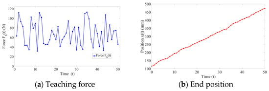
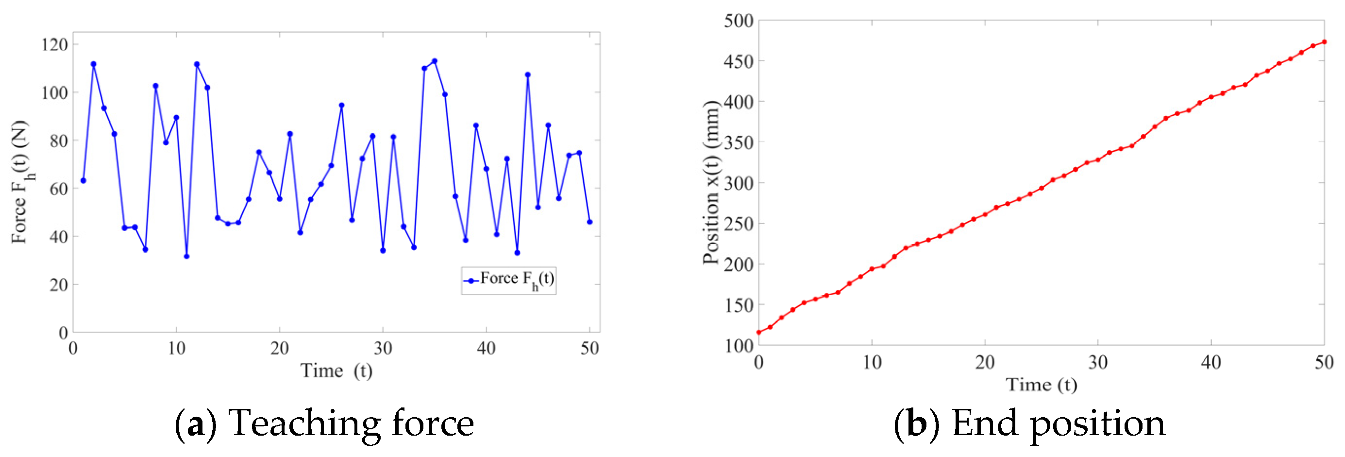
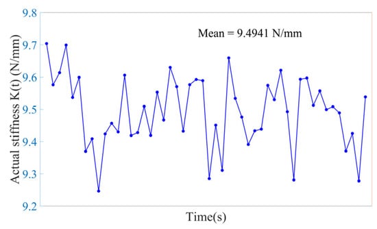
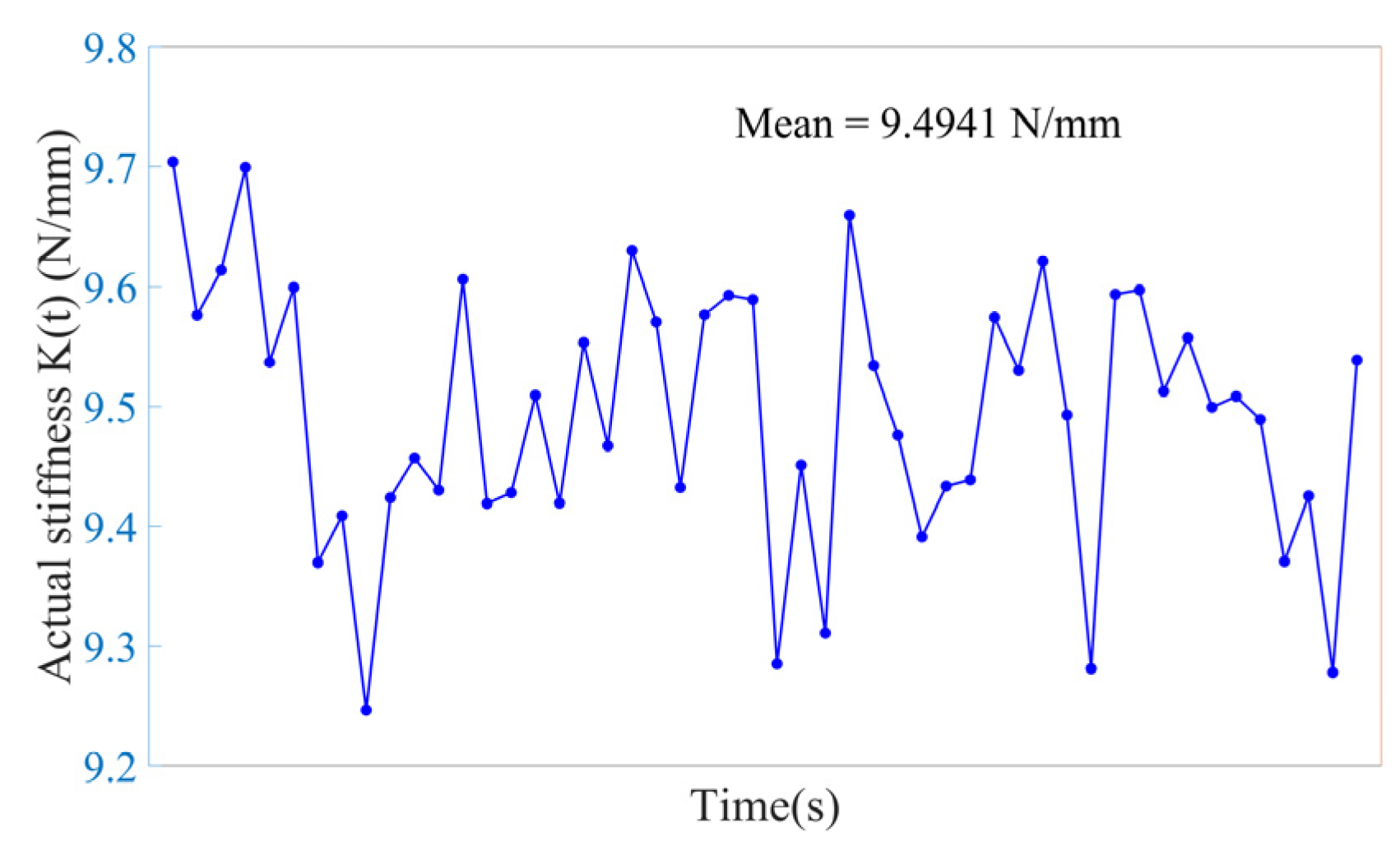
As shown in Figure 9 and Figure 10, through experimental analysis conducted on the X-axis, the threshold is determined, and using the same method, is set to 9.5 for both the Y-axis and Z-axis.
Figure 9.
Experimental results of teaching force and position on the X-axis.
Figure 10.
Actual stiffness.
Thus, the correctness of the selection of and is verified.
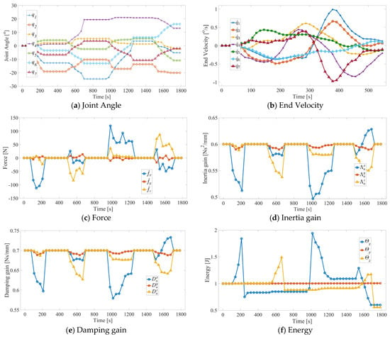
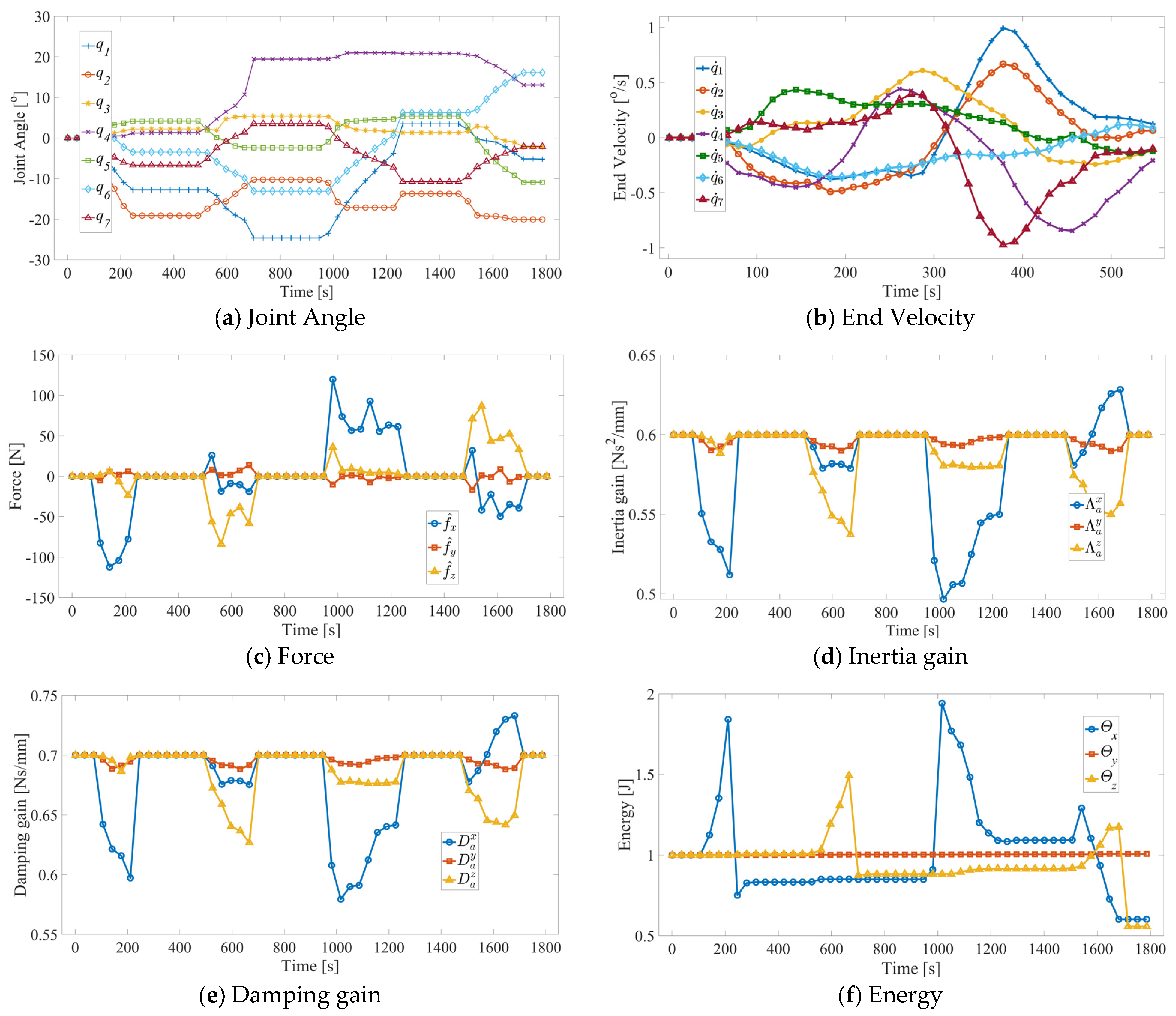
In stage 4, and are adaptively adjusted based on the reference force , still under the constraints of Equations (52) and (53), as shown in Figure 11d,e. At the end of the motion, , thus verifying that the system maintains passivity in the z-axis direction. However, with changes in arm stiffness, fluctuations in occur. The system adaptively adjusts and based on Equations (55) and (56), as shown in Figure 11c. Unlike the previous three stages, and consume energy in the x-axis direction, denoted as , and adaptively increase and , as shown in Figure 11d–f, thereby maintaining the smooth velocity of the robot end-effector in the x-axis direction, as shown in Figure 11b. At the end of the motion, , maintaining passivity in the x-axis direction, thus verifying the effectiveness of the energy-based variable admittance compliant control method proposed in this paper.
Figure 11.
Experimental results of variable admittance control based on external force prediction.
Figure 11 shows the experimental results of the variable admittance compliant control based on the proposed external force estimation. As can be seen from Figure 11c, exhibits four distinct stages of variation throughout the experiment, with the results summarized in Table 4.
Table 4.
End-effector motion of variable admittance compliant control based on external force estimation.
Since the arm stiffness does not undergo abrupt changes in stages 1 to 3, human–machine interaction is achieved using the variable admittance compliant control based on Equations (52) and (53). As shown in Figure 11c–e, and vary synchronously with the reference force in Table 4, maintaining the same gain ratio. This verifies the effectiveness of the variable admittance compliant control method, which operates under the condition that the arm stiffness does not undergo abrupt changes.
From Figure 11b,f, it can be observed that during the acceleration phase in the first three stages, the decrease in injects energy into the system, causing the value of to increase. However, during the deceleration phase, when the reference force decreases, the increase in consumes the robot system’s energy . Nevertheless, under the condition that the arm stiffness does not undergo abrupt changes, , indicating that the system does not lose passivity.
Although throughout the entire experiment, due to changes in the human–machine interaction force, , , and in the variable admittance control vary, the robot control system consistently maintains the passivity constraint, ensuring the stability of the system. Ultimately, the robot is able to operate smoothly while estimating the force applied by the human hand, with its joint angles and end-effector speed changing continuously, without exceeding the limits, as shown in Figure 11a,b.
4. Conclusions
This paper proposes an improved variance-calibrated external force estimation and variable admittance compliant control method for sensorless human–robot interaction in low-speed operations, with a particular focus on industrial applications such as hand-guided teaching, collaborative assembly, and safe concurrent manipulation within the context of Industry 5.0. By modeling robot dynamic model errors and interaction forces as random variables following normal distributions, a stochastic external force estimation framework was established. An improved particle swarm optimization algorithm was introduced to calibrate the variance parameters, enhancing the accuracy and robustness of external force estimation without requiring force sensors.
To address the instability caused by sudden changes in human arm stiffness—a common challenge in industrial hand-guiding tasks where operators may unintentionally or intentionally vary arm stiffness—an energy-based variable admittance control strategy was developed. By introducing an energy storage function and switching factors, the passivity conditions for variable admittance control were derived, enabling adaptive adjustment of inertia and damping gains while maintaining system passivity.
Experimental validation was conducted on a redundant robot platform. The external force estimation experiments demonstrated that the proposed method effectively estimates human–robot interaction forces, with estimation errors below 3 N.m along the x-axis and estimated force trends consistent with sensor measurements. Collision detection experiments showed that the proposed method outperforms the first-order generalized momentum observer approach, achieving smaller detection delays, peak errors, RMSE, and MAE in both x- and y-directions. The variable admittance control experiments verified that the proposed energy-based adaptive strategy maintains system passivity under both normal operation and sudden arm stiffness changes, ensuring stable and compliant human–robot interaction throughout the entire motion trajectory.
The main contributions of this work lie in establishing a variance-based external force estimation model by modeling dynamic model errors and interaction forces as stochastic quantities, with variance parameters optimized via an improved particle swarm algorithm to improve estimation accuracy. Furthermore, the energy-based variable admittance control strategy guarantees passivity under varying human arm stiffness, addressing a critical safety concern in industrial human–robot collaboration.
The proposed method is particularly well-suited for industrial scenarios where force sensors are impractical due to cost, integration complexity, or reduced end-effector stiffness. Its ability to enable sensorless force estimation and maintain stable interaction under varying operator stiffness supports the development of intuitive, safe, and flexible human–robot collaboration systems in real-world manufacturing environments. Future work will focus on extending the method to higher-speed operations and validating its performance in large-scale industrial settings with complex task sequences.
Author Contributions
J.W.: Conceptualization, Methodology, Writing—Original Draft, and Supervision; Z.Z.: Software, Validation, Investigation, and Writing—Original Draft; N.Y.: Software, Validation, and Visualization; X.Z.: Conceptualization, Resources, and Writing—Review and Editing; K.W.: Supervision, Writing—Review and Editing, and Funding Acquisition. All authors have read and agreed to the published version of the manuscript.
Funding
This research was funded by the National Natural Science Foundation of China (No. 52305381) and the Fundamental Research Funds for the Central Universities (No. 30924010937).
Data Availability Statement
The data that support the findings of this study are available from the corresponding author upon reasonable request.
Conflicts of Interest
The authors declare no conflicts of interest.
References
- Jia, J.D.; Zhang, M.L. Research progress and development trend of the safety of human-robot interaction technology. J. Mech. Eng. 2020, 56, 16–30. [Google Scholar] [CrossRef] [Scilit]
- Zhao, X.W.; Chen, Y.M.; Qian, L.; Tao, B.; Ding, H. Human–Robot Collaboration Framework Based on Impedance Control in Robotic Assembly. Engineering 2023, 30, 83–92. [Google Scholar] [CrossRef] [Scilit]
- Safavi, F.; Olikkal, P.; Pei, D.Y.; Kamal, S.; Meyerson, H.; Penumalee, V.; Vinjamuri, R. Emerging Frontiers in Human–Robot Interaction. J. Intell. Robot. Syst. 2024, 110, 45. [Google Scholar] [CrossRef] [Scilit]
- Cho, Y.; Kim, W.; Park, H.; Kim, J.; Na, Y. Bidirectional Double-Spring Pneumatic Artificial Muscle With Inductive Self-Sensing. IEEE Robot. Autom. Lett. 2023, 8, 8160–8167. [Google Scholar] [CrossRef] [Scilit]
- Lu, J.; Lv, X.; Liu, J.; Liu, H.; Huang, T. Fully flexible wearable pouch pneumatic artificial muscle based on asymmetric expansion. Chin. J. Mech. Eng. 2026, 39, 100085. [Google Scholar] [CrossRef] [Scilit]
- Zhao, P.; Gao, Z.; Liu, X.; Zeng, Y.; Zhou, Y. Collision observation of collaborative robots based on generalized momentum deviation. J. Mech. Eng. Sci. 2025, 239, 2529–2543. [Google Scholar] [CrossRef] [Scilit]
- Chien, S.-H.; Wang, J.-H.; Cheng, M.-Y. Performance Comparisons of Different Observer-Based Force-Sensorless Approaches for Impedance Control of Collaborative Robot Manipulators. In Proceedings of the 2020 IEEE Conference on Industrial Cyberphysical Systems (ICPS), Tampere, Finland, 10–12 June 2020; pp. 326–331. [Google Scholar] [CrossRef] [Scilit]
- Fu, L.; Zhao, J. Maxwell model based compliance control for human robot friendly interaction. IEEE Trans. Cogn. Dev. Syst. 2021, 13, 118–131. [Google Scholar] [CrossRef] [Scilit]
- Jia, Q.X.; Xu, T.; Chen, G.; Sun, H.X.; Wang, Y.Q. Coordinated impedance control of robonaut based on disturbance observer. Robot 2018, 40, 860–869. [Google Scholar] [CrossRef]
- Zhang, Y.; Jeong, C.-S.; Kim, M.; Jin, S. Force-free control for direct teaching of a surgical assistant robot end effector with wire-driven bidirectional telescopic mechanism. Sensors 2021, 21, 3498. [Google Scholar] [CrossRef] [Scilit]
- Yuan, J.J.; Qian, Y.J.; Gao, L.M.; Yuan, Z.H.; Wan, W.W. Position-based impedance force controller with sensorless force estimation. Assem. Autom. 2019, 39, 489–496. [Google Scholar] [CrossRef] [Scilit]
- Li, Y.; Zhu, L.S.; Liu, J.Y.; Guo, S.J. Dynamic Model Identification for Whole-arm Compliance Control. J. Mech. Eng. 2022, 58, 45–54. [Google Scholar] [CrossRef] [Scilit]
- Kommuri, S.K.; Han, S.; Lee, S. External Torque Estimation Using Higher Order Sliding-Mode Observer for Robot Manipulators. IEEE ASME Trans. Mechatron. 2022, 27, 513–523. [Google Scholar] [CrossRef] [Scilit]
- Xiao, J.; Dou, S.; Zhao, W.; Liu, H. Sensorless human-robot collaborative assembly considering load and friction compensation. IEEE Robot. Autom. Lett. 2021, 6, 5945–5952. [Google Scholar] [CrossRef] [Scilit]
- Sharifi, M.; Zakerimanesh, A.; Mehr, J.K.; Torabi, A.; Mushahwar, V.K.; Tavakoli, M. Impedance variation and learning strategies in human-robot interaction. IEEE Trans. Cybern. 2022, 52, 6462–6475. [Google Scholar] [CrossRef] [Scilit] [PubMed]
- Tang, Y.C.; Zhang, J.F.; Wu, S.; Sun, F.L.; Kuang, S.L.; Sun, L.N. Safety strategy of surgical robot admittance control based on virtual fixtures. Robot 2019, 41, 842–848. [Google Scholar] [CrossRef]
- Caballero-Mora, J.A.; de Jesús Portillo-Vélez, R.; Vásquez-Santacruz, J.A.; López-González, A.; Hernández-Martínez, E.G. Admittance-based robot force control without velocity and force sensors. Control Theory Technol. 2025, 23, 494–512. [Google Scholar] [CrossRef] [Scilit]
- He, W.; Xue, C.; Yu, X.; Li, Z.; Yang, C. Admittance-based controller design for physical human-robot interaction in the constrained task space. IEEE Trans. Autom. Sci. Eng. 2020, 17, 1937–1949. [Google Scholar] [CrossRef] [Scilit]
- Karami, A.; Sadeghian, H.; Keshmiri, M.; Oriolo, G. Force, orientation and position control in redundant manipulators in priori-tized scheme with null space compliance. Control Eng. Pract. 2019, 85, 23–33. [Google Scholar] [CrossRef] [Scilit]
- Xu, Z.; Li, S.; Zhou, X.; Cheng, T. Dynamic neural networks based adaptive admittance control for redundant manipulators with model uncertainties. Neurocomputing 2019, 357, 271–281. [Google Scholar] [CrossRef] [Scilit]
- Yu, X.; He, W.; Li, Y.; Xue, C.; Li, J.; Zou, J.; Yang, C. Bayesian estimation of human impedance and motion intention for human-robot collabo-ration. IEEE Trans. Cybern. 2021, 51, 1822–1834. [Google Scholar] [CrossRef] [Scilit]
- Wan, J.; Yao, J.; Yu, L.; Zhang, L.; Wu, H. Obstacle avoidance algorithm for redundant manipulators based on pseudo-distance method. J. Mech. Eng. 2020, 56, 59–70. [Google Scholar] [CrossRef] [Scilit]
- Chen, J.; Ro, P.I. Human intention-oriented variable admittance control with power envelope regulation in physical human-robot interaction. Mechatronics 2022, 84, 102802. [Google Scholar] [CrossRef] [Scilit]
- Xu, J.M.; Zhao, Z.P.; Dong, J.W. Free-force control of flexible robot joint system without sensors on link side. J. Zhejiang Univ. Eng. Sci. 2020, 54, 1256–1263. [Google Scholar] [CrossRef]
- Chan, T.F.; Dubey, R.V. A weighted least-norm solution based scheme for avoiding joint limits for redundant manipulators. In Proceedings of the IEEE International Conference on Robotics and Automation, Atlanta, GA, USA, 2–6 May 1993; Volume 3, pp. 395–402. [Google Scholar] [CrossRef] [Scilit]
- Xu, Q.; Sun, X. Adaptive operation-space control of redundant manipulators with joint limits avoidance. In Proceedings of the 2018 Tenth International Conference on Advanced Computational Intelligence (ICACI), Xiamen, China, 29–31 March 2018; pp. 358–363. [Google Scholar] [CrossRef] [Scilit]
- Papageorgiou, D.; Atawnih, A.; Doulgeri, Z. A passivity based control signal guaranteeing joint limit avoidance in redundant robots. In Proceedings of the 2016 24th Mediterranean Conference on Control and Automation (MED), Athens, Greece, 21–24 June 2016; pp. 569–574. [Google Scholar] [CrossRef] [Scilit]
- Olsen, M.M.; Swevers, J.; Verdonck, W. Maximum Likelihood Identification of a Dynamic Robot Model: Implementation Issues. Int. J. Robot. Res. 2002, 21, 89–96. [Google Scholar] [CrossRef] [Scilit]
- Wei, Y.; Lyu, S.; Li, W.; Yu, X.; Wang, Z.; Guo, L. Contact Force Estimation of Robot Manipulators With Imperfect Dynamic Model: On Gaussian Process Adaptive Disturbance Kalman Filter. IEEE Trans. Autom. Sci. Eng. 2024, 21, 3524–3537. [Google Scholar] [CrossRef] [Scilit]
- Larsen, T.D.; Andersen, N.A.; Ravn, O.; Poulsen, N.K. Incorporation of time delayed measurements in a discrete-time Kalman filter. In Proceedings of the 37th IEEE Conference on Decision and Control (Cat. No.98CH36171), Tampa, FL, USA, 18 December 1998; Volume 4, pp. 3972–3977. [Google Scholar] [CrossRef] [Scilit]
- Nanda, S.K.; Kumar, G.; Bhatia, V.; Singh, A.K. Kalman Filtering With Delayed Measurements in Non-Gaussian Environments. IEEE Access 2021, 9, 123231–123244. [Google Scholar] [CrossRef] [Scilit]
- Li, H.-Y.; Nuradha, T.; Xavier, S.A.; Tan, U.-X. Towards a compliant and accurate cooperative micromanipulator using variable admittance control. In Proceedings of the 2018 3rd International Conference on Advanced Robotics and Mechatronics (ICARM), Singapore, 18–20 July 2018; pp. 230–235. [Google Scholar] [CrossRef] [Scilit]
- Wan, J.; Ding, L.; Yao, J.; Wu, H. A hybrid CHAOS-PSO algorithm for dimensional synthesis of a redundant manipulator based on tracking trajectories without or with singularities. Prod. Eng. 2018, 12, 579–587. [Google Scholar] [CrossRef] [Scilit]
- Oaki, J.; Adachi, S. Vibration Suppression Control of Elastic-Joint Robot Arm Based on Designless Nonlinear State Observer. IEEJ Trans. Ind. Appl. 2015, 135, 571–581. [Google Scholar] [CrossRef] [Scilit]
- Zhang, P.; Li, Y. New Indices for Evaluating Vibration Characteristics of Flexible-Joint Robots. Appl. Sci. 2020, 10, 4895. [Google Scholar] [CrossRef] [Scilit]


Disclaimer/Publisher’s Note: The statements, opinions and data contained in all publications are solely those of the individual author(s) and contributor(s) and not of MDPI and/or the editor(s). MDPI and/or the editor(s) disclaim responsibility for any injury to people or property resulting from any ideas, methods, instructions or products referred to in the content. |
© 2026 by the authors. Licensee MDPI, Basel, Switzerland. This article is an open access article distributed under the terms and conditions of the Creative Commons Attribution (CC BY) license.