


Abstract
Background: Flexible surgical instruments for Robot-Assisted Minimally Invasive Surgery (RAMIS) face a critical limitation: the inability to rotate the distal head while the instrument is in a bent configuration, which restricts the maneuverability in narrow surgical workspaces. Methods: This paper presents a novel 4-degree-of-freedom (DOF) flexible laparoscopic instrument with a 10 mm diameter, incorporating a 3D-printed flexible element. The design enables independent bending (0–90°), continuous distal head rotation (360°), gripper actuation (0–60°), and rod rotation (180°). A constant-curvature kinematic model was developed. The instrument was manufactured using PolyJet 3D printing technology and integrated with the ATHENA parallel robot for proof-of-concept experimental validation. Results: Experimental tests demonstrated successful independent 360° distal head rotation across the full bending range (0–90°), validated through simulated surgical procedures including stomach retraction. Quantitative characterization using optical motion capture revealed a maximum angular deflection of 79.85° at 670 g applied load, with tip displacements of 74.95 mm (X) and 91.18 mm (Y). The measured grasping force was approximately 2 N, tip position repeatability was ±2.86 mm, and fatigue testing demonstrated no degradation after 500 bending cycles, confirmed by digital microscope inspection. The instrument performed multiple manipulation tasks, including elastic band transfer, wire path navigation, spring manipulation, and tissue grasping. Conclusions: The proposed instrument addresses a significant white spot in surgical robotics by adding an additional functional capability enabling grasper reorientation without repositioning the entire instrument.
1. Introduction
Surgical practice continues to evolve, with ongoing efforts to develop new approaches and techniques that improve patient outcomes by making procedures safer, less traumatic, and more effective [1], as illustrated in Figure 1.
Figure 1.
The evolution of surgical procedures.
1.1. Minimally Invasive Surgery
Minimally invasive surgery (MIS) has transformed surgical practice since its broad adoption in the 1980s, with laparoscopic cholecystectomy reported in 1988 [2,3]. MIS procedures are performed through small incisions (typically 5–15 mm) using long, specialized instruments and an endoscopic camera; in laparoscopy these are introduced via trocars placed through the abdominal wall to access internal organs [4,5,6,7]. MIS generally reduces postoperative pain, hospitalization and recovery time, blood loss, infection risk, and scarring, largely due to reduced tissue trauma, and it can also reduce postoperative adhesions [8,9,10,11]. In the United States, MIS is widely used, including most Nissen fundoplications and cholecystectomies, and roughly 600,000 hernia repairs annually [12].
Despite these benefits, MIS introduces major technical constraints: limited instrument dexterity compared to the human hand, the fulcrum effect at the trocar, reduced/absent haptic feedback, restricted view and depth perception from 2D monitors, and amplification of hand tremor at the tool tip [13,14,15,16,17,18]. Consequently, MIS demands substantial training for hand–eye coordination and adaptation to counterintuitive movements, and while complications are uncommon, they can be severe; for example, undetected laparoscopy–related bowel injury has been associated with a 3.6% mortality rate [19,20].
1.2. Robot-Assisted Minimally Invasive Surgery
Robot-assisted minimally invasive surgery (RAMIS) retains key MIS benefits (reduced trauma, bleeding, and hospitalization) while addressing issues such as reduced accuracy, fatigue, and hand–eye coordination challenges linked to the lever/fulcrum effect [21]. Most RAMIS systems use a multiport setup in which several robotic manipulators operate Robotic Surgical Tools (RSTs) inserted through small ports, while the surgeon controls the procedure from a teleoperation console that serves as the human–robot interface [22,23,24]. These platforms typically improve visualization (3D vision with depth perception) and enable high-precision tool motion control [24].
The da Vinci Surgical System (Intuitive Surgical, Inc., Sunnyvale, CA, USA) is the most widely used robotic platform for laparoscopic procedures [25]. As a master–slave system, it provides an ergonomic surgeon console and a 3D stereoscopic vision system that enhances field of view and supports more natural hand–eye coordination [26,27]. Its architecture commonly relies on multiple robotic arms operating specialized laparoscopic instruments via small ports [22]. More recently, the da Vinci SP single-port platform was developed and approved for single-incision laparoscopic surgery (SILS), using a single port to introduce a flexible telescope and three instruments [28,29]. Overall, da Vinci and similar RAMIS systems aim to improve dexterity, precision, hand–eye coordination, and surgeon ergonomics.
1.3. Flexible Manipulators Used in RAMIS
The evolution of Robotic Surgical Tools (RSTs) in RAMIS has enabled advanced distal tips with flexible segments (Figure 2a,b), which offer clear advantages over rigid instruments. By improving dexterity and access in confined surgical spaces, these flexible laparoscopic tools help mitigate restricted maneuverability and the fulcrum effect. A major development is the EndoWrist instrument family, used in the da Vinci Surgical System, which enables active tool orientation.
Figure 2.
Types of surgical instruments: (a) classical laparoscopic tool; (b) flexible laparoscopic tool.
The da Vinci Surgical System uses the EndoWrist instrument family, which is wire-driven and enables wrist-like pitch and yaw motions, improving dexterity compared with conventional laparoscopic tools but cannot rotate the distal head along its longitudinal axis [30,31,32,33,34].
Flexible continuum manipulators extend RAMIS by improving adaptability in narrow workspaces, increasing dexterity and range of motion, and enabling manipulation inside the body with less reliance on pivoting about the trocar [35,36,37,38]. Current flexible laparoscopic tools are generally classified as Tendon-Driven Manipulators (TMs), which use cables, and Concentric Tube Manipulators (CTMs), which use nested pre-curved tubes to control shape [39,40]. A key trade-off is that higher dexterity often reduces stiffness and force capability, which can compromise stability during tissue manipulation [41,42].
1.4. Paper Objective and Structure
To address this white spot, this paper presents the design of a 4–DOF surgical laparoscopic instrument that incorporates a 3D-printed flexible element within its distal section. The proposed design can achieve a wide bending range adding also an independent rotation of the distal head to enable grasper reorientation without repositioning the instrument.
This paper is structured in seven sections; Section 2 presents a comparative analysis of 38 existing flexible surgical instruments to identify research white spots. Section 3 details the mechanical architecture and kinematic modeling. Section 4 describes the mechanical design, finite element analysis, prototype manufacturing using 3D printing technology, and control system. Section 5 presents experimental results including kinematic performance testing, fatigue testing with digital microscope inspection, grasping force measurement, tip position repeatability assessment, load-deflection characterization using optical motion capture, functional manipulation tests, and a simulated pancreatic surgery procedure. Section 6 discusses the achieved results, design trade-offs, comparison with existing instruments, and limitations. Finally, Section 7 presents the conclusions and future research directions.
2. Comparative Analysis of Flexible Surgical Instruments
To assess the main limitations of current state-of-the-art technologies, a comprehensive analysis of different flexible surgical instruments was performed and detailed in the following subchapters.
An analysis of 38 flexible surgical instrument designs was performed to analyze the current developments and identify design challenges [43,44,45,46,47,48,49,50,51,52,53,54,55,56,57,58,59,60,61,62,63,64,65,66,67,68,69,70,71,72,73,74,75,76,77,78,79,80,81]. The main parameters of the analysis include: DOF, maximum bending angle, capability for distal head rotation while bent, instrument diameter, and actuation type.
During the analysis different designs were identified, the tendon actuation is the most used actuation type, used in instruments with 4-DOFs [43,44] and for more complex instruments with six or more DOFs [45,46,47,60,61,73]. Other actuation methods are represented by pneumatic systems with force sensing [48], linear electric actuators [50], and the use of Shape Memory Alloys (SMA) [49].
The most common materials for the manufacturing of flexible laparoscopic tools and for the backbone of the instrument are represented by the Nitinol and stainless steel, used for their elasticity and strength [43,50,51,77]. Complex monolithic structures [52], customizable tools [53], and flexible joints with different stiffness [54,71] can be developed using additive manufacturing technology.
Usually, higher dexterity is achieved by instruments with very small diameters (2–4 mm) [55,56,57,74,75,79,80] while the instruments that maintain a higher force capability, from 5 to 10 N, usually have a large diameter and an increased structural complexity [50,58,59,68,76]. Different architectures are used to achieve the necessary dexterity such as serpentine continuum robots [60,67], snake-like robots with discrete joints [61,62,78], and hybrid designs [58,63,64].
Specialized surgical flexible tools have been developed for different surgical procedures such as trans anal endoscopic microsurgery (TEMS) [68,69], endoscopic endonasal neurosurgery [70,79], single-port surgery [63,71,72], and gastrointestinal endoscopy [53], with bending angles starting from 45° [59] to over 160° [66,67,77].
A representative selection of these instruments is illustrated in Table 1, focusing on most relevant parameters such as DOF, bending angle, distal head rotation, diameter, and actuation type. Complete data for all analyzed instruments are available upon request.
Table 1.
Comparison of different flexible laparoscopic surgical instruments.
The analysis performed on 38 instruments [43,44,45,46,47,48,49,50,51,52,53,54,55,56,57,58,59,60,61,62,63,64,65,66,67,68,69,70,71,72,73,74,75,76,77,78,79,80,81] revealed a functional limitation: none of the analyzed instruments including da Vinci EndoWrist demonstrated the capability for independent distal head rotation while in a bent configuration. While important innovations were achieved such as dexterous bending [62,78], compliant backbone structures [50,51], and rolling contact joints [55], this specific capability remains absent from analyzed designs.
This limitation is particularly significant in procedures where the surgeon must often approach tissue from angles that require simultaneous bending and grasper reorientation. The inability to independently rotate the distal head forces repositioning of the entire instrument increasing operative time and complexity.
This work addresses this limitation by developing a 10 mm laparoscopic instrument that combines bending with independent distal head rotation.
3. Kinematic Modeling
This chapter presents a simplified, kinematic model for a tendon-driven flexible surgical instrument with triangular notches. The model focuses on geometric relationships and does not account for friction, elastic deformation, or dynamic effects. The instrument achieves controlled bending through a series of triangular notches embedded into a cylindrical tube, actuated by antagonistic tendon pairs.
The kinematic model is based on the constant curvature assumption, which states that the flexible section bends into a circular arc with uniform curvature when actuated. This assumption is valid when notches are uniformly distributed, and the bending is dominated by geometric compliance rather than material elasticity.
3.1. Mechanical Architecture of the Flexible Instrument
The architecture of the instrument is illustrated in Figure 3 and is mainly based on the flexible element illustrated in the figure, manufactured using Elastico PolyJet Photopolymer on a Stratasys MediJet 3D printer (Stratasys Ltd., Eden Prairie, MN, USA) [82].
Figure 3.
The kinematic scheme of the proposed robotic surgical instrument (bending angle = 45°).
This flexible laparoscopic instrument has four DOF: the first one for the bending of the flexible element (q1), the second one for the rotational movement of the distal head (q2), the third one for the open and close movements of the forceps (q3), and the last one for the rotation of the entire rod (q4). The flexible element has a determined number of notches (n), each notch forms an angle (2α) as illustrated in Figure 3. Similarly, on the other side of the flexible element, an equal number of notches were performed to reduce the deformation of the elastic element and to reduce the actuation force. Two sets of wires guided using rigid tubes embedded into the flexible material are used to perform the bending and unbending movements of the flexible element. The grasping function is achieved using a scissor mechanism.
3.2. Geometric Parameters
The flexible surgical instrument design allows for parametric customization based on surgical requirements. Table 2 presents the design parameters specific values used for the Minimum Viable Product (MVP) experimental prototype developed in this study.
Table 2.
Instrument design parameters.
The geometric design of the flexible section in the initial configuration is presented in Figure 4a and the tendons in Figure 4b. The tube with the diameter D and length Lf presents an alternating pattern of triangular notches into opposite sides. On the upper surface, notches labeled L1–L6 are positioned at regular intervals; on the lower surface, notches R1–R6 are offset longitudinally to create the alternating pattern. When the instrument bends, notches on the compression side close while notches on the tension side open. Each notch is characterized by identical parameters: half-angle α, notch depth h, and hinge length Lh. The material remaining at each hinge acts as a flexural element that enables controlled rotation. The tendons pair T1, T2 is positioned on the upper side and unbending pair T3, T4 on the lower side, both at radial distance corresponding to the effective moment arm deff. The total number of notches n per side directly determines the maximum achievable bending angle.
Figure 4.
Undeformed flexible section: (a) open notch geometry; (b) position of the tendons.
The geometry of the notch is illustrated in Figure 5. Figure 5a presents geometry of the open notch in the undeformed position, with main dimensions. The triangular notch is defined by the half-angle α measured from the vertical centerline, resulting in a full notch opening angle of 2α. The notch depth “h” extends to the neutral axis to maximize bending capacity. The hinge length Lh represents the material at the notch apex and is geometrically related to the other parameters. Figure 5b illustrates the notch closing mechanism during the bending. The original open notch profile progressively closes as the tube curves. The partially closed state shows an intermediate bending condition. When the opposing notch surfaces make contact, the notch is fully closed and maximum rotation of 2α per notch is achieved.
Figure 5.
Detailed geometry of the triangular notch: (a) open notch geometry; (b) notch closing.
Each triangular notch creates a compliant hinge. The hinge length Lh is the width of the notch opening at the outer surface of the tube, determined by the notch depth h and the notch half-angle α:
When a triangular notch fully closes, the tube bends by the full notch angle 2α. The maximum bending angle per notch is:
For n notches acting in series on one side, the total maximum bending angle is:
For the design parameters (n = 6, α = 7.5°): θmax = 6 × 15° = 90°.
3.3. Constant Curvature Kinematics
The kinematic model is based on the constant curvature assumption:
- -
- The flexible section bends into a circular arc with uniform curvature;
- -
- Notches are uniformly distributed along the flexible section;
- -
- Planar bending only (no torsion);
- -
- Proximal and distal sections remain rigid.
For a flexible section of length Lf bent through angle θ, the curvature κ and radius of curvature are:
The arc length parameter “s” varies along the flexible section, and the local bending angle at position s is:
The centerline of the flexible section follows a circular arc. In the XZ plane, with the base of the flexible section at position (0, Lp):
For θ ≠ 0 (bent configuration):
For θ → 0 (straight configuration):
At the end of the flexible section (s = Lf), the tip position is:
The distal rigid section of length Ld extends from the flexible tip at angle θ. The end-effector position is:
The kinematic behavior of the instrument across the operational range is illustrated in Figure 6. Eight configurations starting from the straight position θ = 0° to maximum bending θmax are displayed to illustrate the continuous nature of the deformation. In Figure 6a, the centerline trajectories are illustrated. Figure 6b presents the complete instrument profiles including inner and outer tube surfaces.
Figure 6.
Distal head: (a) centerline trajectories; (b) complete instrument profiles displaying inner surface (blue), outer surface (red), and centerline (dashed) at each configuration.
3.4. Tendon Kinematics
Four tendons are arranged in two antagonistic pairs at a radial distance rt = 4 mm from the tube centerline. The tendons are offset by angle β = 22.5° from the bending axis (Y-axis) as illustrated in Table 3.
Table 3.
Geometric parameters.
The Cartesian coordinates of tendon “i” in the cross-sectional plane are:
For bending in the XZ plane, the moment arm of each tendon is its perpendicular distance from the neutral bending axis, which corresponds to the Y-coordinate:
The effective moment arm for the tendon pairs in the proposed design is:
For constant curvature bending, the length change of each tendon is proportional to its moment arm and the bending angle:
The negative sign indicates that tendons with positive moment arms shorten when the bending angle increases.
For the antagonistic pair configuration, bending tendons (T1, T2); positive moment arm → shorten when bending
Unbending tendons (T3, T4): negative moment arm → lengthen when bending
At maximum bending for the proposed design (θ = 90° = π/2 rad = 1.571 rad):
- -
- Bending tendons (T1, T2): ΔL = −3.70 × 1.571 = −5.81 mm (pull)
- -
- Unbending tendons (T3, T4): ΔL = +3.70 × 1.571 = +5.81 mm (release)
The actuation characteristics of the tendon-driven mechanism are illustrated in Figure 7, where the relationship between tendon displacement ΔL and bending angle θ is presented. Two curves represent the behavior of the antagonistic tendon pairs: the bending tendons T1 and T2 present negative displacement, and the unbending tendons T3 and T4 presents positive displacement. The strict linear relationship of ΔL arrive from the constant curvature kinematics, where (17) represents the effective moment arm determined by the tendon radial position rt and angular offset β.
Figure 7.
Tendon length variation (ΔL) as a function of bending angle (θ).
4. The Flexible Surgical Laparoscopic Instrument
The mechanical design and prototype manufacturing of the flexible surgical laparoscopic instrument are presented in this chapter.
The development process starts with clinical requirements and design criteria that define the main functionalities of the instrument. The CAD design is performed based on these requirements, where the instrument is 3D modeled. To verify the structural integrity of the flexible element and of the distal head tip jaw a finite element analysis (FEA) was performed. The last part of the development process is represented by the prototyping of the surgical instrument using 3D printing technology.
4.1. Design Criteria for the Flexible Surgical Instrument
The instrument design was guided by criteria derived from the literature and clinical requirements. The primary dimensional constraint is a maximum outer diameter of 10 mm to ensure compatibility with standard laparoscopic ports [83,84,85,86], while maximizing the inner-to-outer diameter ratio to accommodate actuation tendons [87]. Kinematically, the instrument requires multiple degrees of freedom [83] with independent distal actuation to provide sufficient dexterity [84] and workspace coverage [84]. Mechanical performance criteria include precise motion control [84], structural stability during tissue manipulation [84], adequate force capability below 5 N for soft tissue handling [86], and fatigue resistance for tendon-driven components [53,84]. Manufacturing considerations prioritize cost-effectiveness and ease of maintenance [53,84]. All patient-contacting materials must comply with ISO 10993 biocompatibility standards [53,84], and the instrument should either be sterilizable or designed for single-use manufacturing in sterile conditions [53,88]. Finally, the design should be versatile across different minimally invasive procedures [53,84] and easily deployable through access ports [86].
4.2. Mechanical Design of the Flexible Laparoscopic Instrument
The instrument consists of three main assemblies: the distal tip (flexible element and gripper), the rod (rigid tube with internal transmission elements), and the driving unit (actuation and control modules), as illustrated in Figure 8.
Figure 8.
Main components of the flexible laparoscopic instrument.
4.2.1. Flexible Distal End
The main components of the flexible distal head are illustrated in Figure 9a,b. The distal head is connected to the flexible element and to the flexible metallic wire. To perform the q4 rotation movement, two bearings are used. The flexible metallic wire is connected to the 5 mm rod via connector 1 and the flexible element is connected to the 10 mm rigid rod.
Figure 9.
Flexible distal head: (a) main components and movements; (b) exploded view of the flexible distal head.
Figure 10 illustrates the distal head in both open position, Figure 10a and closed position in Figure 10b. The grasping function is implemented using a bidirectional, push-pull wire mechanism. When the wire is pushed with a certain force, the distal head jaws of the distal head will open and when the wire is pulled the jaws will close as can be observed in the pictures below.
Figure 10.
Distal head: (a) open position; (b) closed position.
The bending capability of the instrument is obtained using a custom-designed flexible element that is manufactured as a single body as illustrated in Figure 11a. This monolithic structure combines a central elastic joint with rigid segments and integrated wire guidance channels, creating a compact assembly.
Figure 11.
Flexible element design: (a) main components; (b) actuation method.
The flexible joint is defined by a pattern of symmetrical notches, enabling controlled bending while minimizing the force needed for actuation. The design incorporates several dedicated channels that are embedded into the structure: channels H1 to H4 guide the bending and unbending wires, channel H5 is used for the gripper actuation wire, and channels H6 and H7 are used to introduce Nitinol reinforcement segments. These Nitinol rods improve the element’s axial stiffness, improving its stability.
The bending motion is driven by a wire system as illustrated in Figure 11b. Pulling the dedicated flexion wires and releasing the extension wires produces the bending of the element, while pulling the opposing extension wires and release the flexion wires returns the element to a straight position.
4.2.2. Driving Unit
The driving unit illustrated in Figure 12 integrates five DC micro-gearmotors with magnetic encoders, controlled by a Raspberry Pi 5 through two Motoron M2H18v18 dual-channel motor controllers via I2C protocol. The complete instrument assembly with all actuation mechanisms is illustrated in Figure 12.
Figure 12.
Driving unit.
The bending motion (q1) is achieved through a dual-motor antagonistic system. Both motors rotate simultaneously, counterclockwise for bending and clockwise for unbending. Each motor shaft drives a roll that tensions the wires through guided paths. The wires are connected to Φ1 mm rods running through the Φ10 mm tube, which in turn connect to the tendons routed through the flexible element. Bearings positioned on dedicated tensioners allow for precise wire tension adjustment.
The distal head rotation (q2) is driven by a single DC motor connected through a mechanical coupler to a 5 mm rigid rod. A dedicated connector links the rigid rod to a flexible metallic wire that passes through the flexible element and attaches to the distal head. The flexibility of the wire allows it to accommodate curvature changes during bending, ensuring continuous 360° rotation capability regardless of the bending configuration.
The gripper actuation (q3) employs a lead screw mechanism that converts rotational motor motion into linear displacement of a translation flange guided by LM3UU linear bearings. The linear movement of the flange pushes or pulls the actuation wire, producing the opening and closing of the gripper jaws.
The rod rotation (q4) is obtained through a bevel gear pair. A DC motor drives the primary bevel gear, which engages a secondary bevel gear fixed to the instrument rod, enabling 180° rotation independently from the other degrees of freedom.
All four degrees of freedom operate independently. In particular, the distal head rotation (q2) remains fully functional at any bending angle, and the rod rotation (q4) does not affect bending or grasping capabilities.
4.3. Finite Element Analysis
This subchapter illustrates the finite element analyses that were performed on the flexible element and on the instrument tip.
The simulation focuses mainly on the correct modeling of the material, boundary condition setup, contact definition, and stress–strain analysis to evaluate the large deformation and force transmission. The flexible element has been developed using an elastic material, a rubber like photo-polymer—Stratasys Elastico, with a Shore of 85 as the primary material.
The flexible element was modeled using tetrahedral elements with a mean length of 0.7 mm. To smooth the areas that experience high deformation, a fine mesh was applied. Modeling the flexible element is very challenging due to the hyper elastic material properties, which involve large deformations and incompressibility. To overcome these difficulties, a hybrid formulation (hybrid elements) was used to model the tube, considered as a nearly incompressible hyper elastic material with a Poisson’s ratio approaching 0.5.
Several methods were tested to define the material, such as the Mooney–Rivlin model, but since at this stage the material properties were not fully defined, the final solution was to define the material as hyper elastic using a Neo-Hookean formulation. This represents a compromise in simulation accuracy due to the limited available information. The model requires only two elastic parameters: C10, the shear modulus component, and D, the compressibility parameter (related to the bulk modulus), where G is the shear modulus and K is the bulk modulus.
To avoid self-penetration, contact pairs were defined for each notch, as illustrated in Figure 13a. The first boundary condition consists of fixing one side of the tube, while two displacement boundary conditions are applied to the other sides of the tube, where the actuation wires pull and apply force to bend the flexible element. The behavior of the wires was replicated by applying a displacement boundary condition in a mobile coordinate system during the simulation, OABC, shown in Figure 13b.
Figure 13.
Modeling and FEM simulation of the flexible element: (a) modeling of the flexible instrument using contact pairs; (b) boundary conditions for the simulation; (c) total displacement during the simulation.
The deformation in the FEM model can be observed in Figure 13c. The elongation at break given by the material manufacturer (360–400%) was converted to logarithmic strain (LE). The results illustrated in Figure 13c present the maximum displacement of 46.61 mm, while the maximum LE is 0.314, under the material limits.
The jaw components of the proposed flexible laparoscopic end-effector are 3D printed using DraftWhite (MED857) (Stratasys Ltd., Eden Prairie, MN, USA) PolyJet resin. The most relevant mechanical, thermal, and physical properties of this material are presented in Table 4.
Table 4.
DraftWhite Material Properties [86].
Using these properties, we validated the structural integrity of the jaw using Finite Element Analysis. A load of 2 N was applied at the tooth contact area, while the proximal mounting region of the jaw was constrained. The resulting von Mises stress field illustrated in Figure 14 shows a maximum stress of approximately 9 MPa, below the tensile strength of DraftWhite.
Figure 14.
Finite element analysis of finger under a 2N force.
The forces required to grasp soft tissue during minimally invasive laparoscopic procedures are usually only a few newtons; measurements of pinch and pull forces at the grasper tip indicate that precise manipulation is generally achieved with forces below approximately 5 N to avoid tissue damage while maintaining a secure grip [87].
4.4. Prototype Manufacturing
The physical prototype of the flexible laparoscopic instrument was manufactured to validate mechanical design. The manufacturing process utilizes PolyJet technology [86], which allows for the creation of complex geometries and multi-material parts in a single build tray.
The assembly followed a modular sequence: first, the Distal Assembly, where actuation wires and Nitinol reinforcements were inserted through the flexible element and the distal head was connected to the flexible element; second, rod integration, connecting the flexible segment to the aluminum tube and inserting the internal stainless steel transmission rods; and finally, actuation unit assembly, where motors were installed and wires tensioned, as illustrated in the Figure 15.
Figure 15.
Prototype of the flexible laparoscopic instrument.
The flexible laparoscopic instrument [88,89] is controlled through a master–slave teleoperation architecture, as illustrated in Figure 16. The hardware platform consists of a Raspberry Pi 5 as the central processing unit, two Motoron M2H18v18 (Pololu Corporation, Las Vegas, NV, USA) dual-channel motor controllers communicating via I2C protocol, and five DC micro-gearmotors with magnetic encoders.
Figure 16.
Hardware architecture of the flexible laparoscopic tool.
The surgeon interacts with the system using a 3Dconnexion SpaceMouse, which provides six analog input channels. The SpaceMouse axes are mapped to the instrument’s four degrees of freedom: vertical translation (Tz) controls gripper actuation (q3), rotation around the X-axis (Rx) controls rod rotation (q4), rotation around the Y-axis (Ry) controls flexible element bending (q1), and rotation around the Z-axis (Rz) controls distal head rotation (q2). Input signals are processed through dead-zone filtering and low-pass smoothing to eliminate hand tremors before being converted to motor velocity commands.
The control software implements a finite state machine with four states: INIT for system initialization, IDLE for standby operation, TELEOP for active teleoperation, and FAULT for error handling. For the bending mechanism, an antagonistic control strategy coordinates the flexion and extension motors to maintain tendon tension throughout the motion range.
5. Results
This section presents the experimental results obtained from testing the 4-DOF flexible laparoscopic instrument. The experiments were performed to demonstrate that the proposed design addresses the identified white spot: the ability to rotate the distal head independently while the instrument is in a bent configuration.
5.1. Kinematic Performance
The kinematic performance of the flexible instrument was evaluated by measuring the range of motion for each degree of freedom. The experimental results are summarized in Table 5.
Table 5.
Kinematic performance results for each degree of freedom.
The flexible element achieved a bending angle of 90°, meeting the design specifications. Critically, the independent distal head rotation (q2) demonstrated continuous 360° rotation capability while the instrument was maintained in a bent configuration, validating the novel design approach that addresses the identified research white spot.
The demonstration of all four degrees of freedom can be observed in Figure 17. The primary innovation of this instrument, the independent distal head rotation while the instrument is in a bent configuration was validated through testing. The rotation mechanism operated successfully across different bending configurations, demonstrating that continuous 360° rotation and the flexible metallic wire transmission accommodated the curvature changes during bending movements.
Figure 17.
Demonstration of the four degrees of freedom: (a) distal head rotation; (b) rod rotation; (c) bending; (d) gripper actuation (q3).
5.2. Fatigue Test
The fatigue resistance of the flexible element was evaluated through cyclic bending tests. A test stand was developed, as illustrated in Figure 18, consisting of a fixed support structure with wire guides that enable controlled manual tensioning of the actuation tendons.
Figure 18.
Fatigue test setup.
The test protocol consisted of 500 complete bending cycles, with each cycle comprising full flexion to the maximum bending angle (90°) followed by return to the straight configuration (0°). Visual inspections were performed at incremental intervals (20, 50, 75, 100, 150, 200, 300, 400, and 500 cycles) to assess the structural integrity of the flexible element. Representative images of the flexible element at selected cycle counts are presented in Figure 19a,b.
Figure 19.
Fatigue test results: flexible element condition after (a) 400 and (b) 500 bending cycles.
Throughout the 500 cycles, no visible damage was observed. The flexible element showed no signs of crack initiation at the notch hinges, no permanent deformation or shape drift, and no degradation of bending performance. The triangular notches maintained their original geometry, and the element consistently achieved the full 90° bending range throughout testing.
In addition to the macroscopic inspections, a TOMLOV (TOMLOV, Shenzhen, China) digital microscope was used to examine the flexible element before testing (0 cycles) and immediately after completing 500 cycles, focusing on areas prone to damage (e.g., notch roots, outer surface, and tendon routing features). The digital microscope setup is shown in Figure 20, while representative post-fatigue microscope images are provided in Figure 21.
Figure 20.
Digital microscope inspection setup used for examination of the flexible element.
Figure 21.
Digital microscope inspection.
No visible cracking, delamination, or surface degradation was observed under the digital microscope after 500 cycles.
5.3. Grasping Force Measurement
The grasping force capability was evaluated experimentally as can be observed in Figure 22 using a force-sensitive resistor (FSR 406, Interlink Electronics, Fremont, CA, USA) integrated into a voltage divider circuit with a 10 kΩ resistor. The sensor was connected to a national instruments data acquisition system (National Instruments Corporation, Austin, TX, USA), and measurements were processed using LabVIEW 2025 (National Instruments Corporation, Austin, TX, USA) software. Calibration was performed using precision weights.
Figure 22.
Grasping force measurement experimental setup.
The FSR sensor was positioned between the gripper jaws, and the gripper was actuated to full closure. The measured grasping force was approximately 1.96 N.
5.4. Repeatability Test
Tip position repeatability was evaluated using millimeter graph paper and manual reading, with an estimated reading uncertainty of approximately ±1 mm. The experimental setup is shown in Figure 23. The instrument was actuated from the straight configuration to the bent configuration using the same actuation command and then returned to the straight configuration. This cycle was repeated for n = 10 consecutive trials. For each trial i, the tip coordinates were recorded in the straight state (Xs,i, Ys,i) and in the bent state (Xb,i, Yb,i).
Figure 23.
Experimental setup for tip position measurements using millimeter graph paper.
To reduce placement and origin-offset effects (e.g., the selected reference point on the paper), repeatability was computed on the within-cycle tip displacement:
Repeatability was reported as the standard deviation (SD) of ΔX and ΔY, and as a combined 2D metric.
Across the 10 cycles, the mean tip displacement was ΔX = 4.50 mm and ΔY = 21.90 mm. The measured repeatability was SD(ΔX) = 1.96 mm and SD(ΔY) = 2.08 mm, corresponding to a 2D repeatability of R2D = ±2.86 mm (SD, n = 10). Figure 24 shows the scatter of the within-cycle displacement points (ΔXi, ΔYi), with the dashed circle indicating the 1 SD repeatability radius R2D.
Figure 24.
Tip displacement repeatability (n = 10) measured on millimeter graph paper.
5.5. Load-Deflection Characterization
The mechanical behavior of the flexible element under external loading was characterized through static bending tests. The experimental setup, illustrated in Figure 25 and Figure 26, consisted of a fixed support structure with the flexible element mounted horizontally, a pulley system for controlled load application, and a precision calibrated weight set. The flexible element was clamped at its proximal end using a custom 3D-printed fixture. A pulley redirected the vertical gravitational force from the hanging weight container into a horizontal pulling force applied to the actuation tendon at the distal end of the flexible element.
Figure 25.
Experimental setup for load-deflection characterization.
Figure 26.
OptiTrack motion capture system.
Position measurements were obtained using an OptiTrack (NaturalPoint Inc., Corvallis, OR, USA) optical motion capture system providing sub-millimeter tracking accuracy. Six reflective markers were attached along the instrument: one at the base (fixed reference), four distributed along the flexible section to capture the deformed shape, and one at the distal tip. The three-dimensional coordinates of each marker were recorded at each load increment.
Calibrated weights ranging from 50 g to 670 g were incrementally applied to the actuation tendon. At each load step, the system was allowed to stabilize for 10 s before recording marker positions. The tip displacement relative to the initial unloaded configuration was calculated from the recorded marker coordinates. The angular deflection (bending angle) was computed using the tangent direction at the distal tip, defined as the vector connecting the fourth intermediate marker to the tip marker.
The experimental results are illustrated in Figure 27. The flexible element exhibited a nonlinear load–deflection relationship characteristic of large-deformation bending. At the maximum applied load of 670 g (equivalent to 6.57 N), the tip achieved a displacement of 74.95 mm in the X direction and 91.18 mm in the Y direction, with an angular deflection of 79.85°.
Figure 27.
Load–deflection characteristics of the flexible element.
The load–deflection curves presented in Figure 27 reveal three distinct behavioral regions. In the initial region (0–150 g), the flexible element demonstrates relatively high compliance, with the angular deflection increasing rapidly from 0° to approximately 31°. The intermediate region (150–420 g) shows a more gradual response as the triangular notches progressively close under increasing load. In the final region (420–670 g), the rate of angular deflection decreases further as the element approaches its geometric bending limit, consistent with the designed maximum bending angle of 90°.
The deformed shape of the flexible element at selected load values is illustrated in Figure 28, showing the progressive curvature from the initial straight configuration to approximately 80° bending at maximum load.
Figure 28.
Deformed shape of the flexible element at selected applied loads (100 g, 207 g, 314 g, 420 g, 570 g, 670 g).
5.6. Workspace Analysis
The workspace of the flexible instrument was experimentally characterized and compared with the theoretical constant-curvature kinematic model. The tip position was measured using an OptiTrack motion capture system across the full bending range (0–90°). Additionally, the rod rotation degree of freedom (q4) was actuated through its complete range of +/−90°, generating the three-dimensional workspace envelope.
The theoretical workspace was computed using the constant-curvature kinematic model with design parameters Lf = 50 mm (flexible section length) and Ld = 55 mm (distal section length). For a given bending angle θ, the tip position was calculated as:
The comparison between theoretical predictions and experimental measurements is illustrated in Figure 29. The experimental data shows good agreement with the constant-curvature model across the operational range. Quantitative error analysis revealed a mean positioning error of 4.10 mm, with a root-mean-square (RMS) error of 4.73 mm. The maximum error of 8.33 mm occurred at the bending angle of 90°.
Figure 29.
Workspace comparison: theoretical vs. experimental.
The three-dimensional workspace, obtained by combining the bending motion with +/−90° rod rotation (q4), is presented in Figure 30. The workspace forms a hemispherical envelope with approximate dimensions of 105 mm in the X direction, 245 mm in the Z direction, and 87 mm in the Y direction.
Figure 30.
The three-dimensional workspace comparison: theoretical vs. experimental.
The observed discrepancies between theoretical and experimental results can be attributed to several factors: tendon friction and hysteresis effects, material viscoelasticity of the Elastico photopolymer, and the discrete notch geometry, which deviates from the ideal continuous curvature assumption at higher bending angles.
5.7. Manipulation and Grasping Tests
To validate that the instrument meets the design objectives, a series of functional tests were performed. These tests were performed to verify the ability of the instrument to perform basic manipulation tasks required for minimally invasive surgery.
Elastic Band Transfer: The surgeon successfully transferred elastic bands between fixed rings, as illustrated in Figure 31a. The task required coordinated use of bending (q1), distal head rotation (q2), and gripper actuation (q3).
Figure 31.
Manipulation and grasping tests: (a) transferring elastic bands between rings; (b) guiding a wire through a path; (c) manipulation of plastic springs; (d) grasping of soft.
Tissue Grasping: The gripper successfully grasped different types of tissue as illustrated in Figure 31d.
Wire Path Navigation: The 10 mm diameter instrument successfully guided a flexible wire through a series of small rings within the training simulator, as shown in Figure 31b. The bending capability allowed the instrument to navigate around obstacles.
Spring Manipulation: The instrument grasped and repositioned plastic springs at various angles, as presented in Figure 31c.
The gripper successfully grasped different types of tissue as illustrated in Figure 31d.
5.8. Simulated Pancreatic Surgery Test
The main objective of the experimental test was to demonstrate the instrument’s capability to perform stomach retraction during simulated pancreatic surgery, following the clinical protocol described in [64].
The instrument was integrated with the ATHENA robot system, which consists of two modules: a parallel robot with four active degrees of freedom for instrument positioning, and a passive spherical mechanism that constrains the Remote Center of Motion (RCM). The experimental setup, illustrated in Figure 32, includes the Athena robot, the flexible surgical instrument, a laparoscopic camera for visual feedback, and 3D-printed pancreas and stomach models placed in the training kit. The surgeon controlled the system using a 3D SpaceMouse.
Figure 32.
Experimental setup of the surgical procedure.
The test scenario focused on stomach manipulation to create an intraoperative workspace for the surgeon. The procedure consisted of the following steps:
- The instrument was introduced through the laparoscopic port and positioned using the Athena parallel robot;
- The flexible element was bent to approach the silicone cord wrapped around the stomach phantom;
- The distal head was rotated to achieve optimal grasping orientation while maintaining the bent configuration;
- The gripper securely grasped the silicone cord;
- The robot performed a coordinated lifting motion to retract the stomach from the pancreas surface;
- The instrument maintained the retracted position, providing workspace access for additional surgical instruments.
As illustrated in Figure 33, the instrument successfully performed the stomach retraction procedure. Figure 33a shows the initial grasping stage, while Figure 33b demonstrates the instrument holding the stomach in a retracted position, providing access to the pancreas.
Figure 33.
Stomach manipulation: (a) initial stage; (b) holding of the stomach.
6. Discussion
The experimental results demonstrate that the proposed instrument can perform independent distal head rotation while in a bent configuration. This capability, identified as a white spot during the analysis of different existing flexible surgical instruments, was successfully implemented through the proposed mechanical architecture.
The primary objective of this work was achieved: the instrument successfully demonstrated independent 360° distal head rotation across the full bending range (0–90°). This capability, absent from analyzed instruments, enables grasper reorientation without repositioning the entire instrument.
The instrument achieved the desired ranges of motion for all four degrees of freedom: 90° bending (q1), 360° continuous distal head rotation (q2), 60° gripper opening (q3), and 180° rod rotation (q4). The decoupled actuation mechanism performed as designed, with the distal head rotation remaining fully functional regardless of the bending angle.
Quantitative performance characterization: comprehensive quantitative testing was performed to characterize the mechanical behavior of the instrument. Fatigue resistance was evaluated through 500 complete bending cycles at maximum deflection (90°), with visual inspections and digital microscope examination at different intervals (20, 50, 75, 100, 150, 200, 300, 400, and 500 cycles). No visible damage, crack initiation, or permanent deformation was observed throughout testing, demonstrating a 5–10× safety margin relative to single-use operational requirements (50–100 cycles per typical procedure).
The grasping force capability was measured using a calibrated FSR 406 force sensor with national instruments data acquisition, yielding approximately 2 N at maximum gripper displacement. This value falls within the clinically relevant range for soft tissue manipulation, where forces below approximately 5 N are recommended to avoid tissue damage while maintaining a secure grip [87]. While sufficient for retraction and grasping tasks as demonstrated in the experimental tests, higher forces would require structural reinforcement.
Tip position repeatability was assessed over 10 actuation cycles using millimeter graph paper, resulting in a 2D repeatability of +/−2.86 mm (SD), with individual axis deviations of SD(ΔX) = 1.96 mm and SD(ΔY) = 2.08 mm. This level of repeatability is consistent with open-loop tendon-driven systems, where hysteresis, cable slack, and friction contribute to cycle-to-cycle variability. For the intended application of visually guided tissue manipulation, the +/−2.86 mm variability is compensated by real-time visual feedback from the laparoscopic camera. Implementation of closed-loop position control using the integrated encoder feedback is expected to reduce this value below 1 mm.
Load-deflection characterization using an OptiTrack optical motion capture system with six reflective markers provided comprehensive data on the flexible element’s mechanical behavior. The nonlinear load–deflection relationship revealed three distinct behavioral regions with quantifiable compliance characteristics: the initial high-compliance region (0–150 g) exhibited a mean angular sensitivity of approximately 0.21°/g, the intermediate region (150–420 g) showed a reduced sensitivity of 0.10°/g as the triangular notches progressively closed, and the stiffening region (420–670 g) further decreased to 0.09°/g as the element approached its geometric bending limit. At the maximum applied load of 670 g (6.57 N), the tip achieved a displacement of 74.95 mm (X) and 91.18 mm (Y), with an angular deflection of 79.85°, reaching 88.7% of the designed maximum of 90°. The remaining 10.2° gap between the load-test result and the full 90° range achieved by the motorized prototype indicates that the actuation system provides sufficient force margin to overcome friction and material resistance across the complete operational range.
Workspace characterization using OptiTrack motion capture revealed a mean positioning error of 4.10 mm and RMS error of 4.73 mm relative to theoretical constant-curvature predictions. The mean error represents 3.9% of the maximum instrument reach (105 mm in the straight configuration), while the maximum error of 8.33 mm (7.9% of reach) occurred at 90° bending, where accumulated effects of discrete notch geometry, tendon friction, and material viscoelasticity deviate most from the ideal continuous-curvature assumption. The error progression across bending angles: 0 mm at 0°, 2.22 mm at 30.9°, 4.74 mm at 57.4°, 6.99 mm at 79.8°, and 8.33 mm at 90° confirms a monotonically increasing trend consistent with the cumulative nature of geometric approximation errors. These positioning errors remain within acceptable limits for visually guided tissue manipulation, though closed-loop control with position feedback would be required for sub-millimeter precision tasks.
The kinematic and FEM models serve independent, complementary purposes: the kinematic model provides the geometric framework for motion planning, while FEM validates structural integrity. Integration through experimentally derived correction factors is identified as future work.
The functional tests were completed successfully. The instrument performed elastic band transfer, wire path navigation, spring manipulation, and tissue grasping without mechanical failures. These tests required coordinated use of multiple degrees of freedom, confirming that the actuation system can handle combined movements.
The integration with the ATHENA parallel robot system was successful. The instrument performed the stomach retraction procedure according to the medical protocol, demonstrating that the proposed design can operate within a robotic surgical system.
The modular manufacturing approach using PolyJet 3D printing technology enabled the fabrication of complex geometries, including the flexible element with embedded channels for tendons and Nitinol reinforcements, in a single build.
The literature analysis revealed that increased dexterity in flexible instruments generally reduces stiffness and force capability. The proposed design reflects this trade-off: the Elastico PolyJet photopolymer (Shore 85A) provides the rubber-like flexibility necessary for the 90° bending range, while the triangular notch geometry concentrates deformation at controlled hinge points (Lh = 1.32 mm per notch). To partially compensate for the inherent compliance, Nitinol reinforcement segments inserted through dedicated channels (H6, H7) improve axial stiffness, reducing buckling risk during tissue manipulation. The FEM analysis confirmed that the maximum logarithmic strain (LE = 0.314) remains well below the material’s elongation at break (360–400%), providing a structural safety factor exceeding three times for the flexible element.
The flexible element uses Elastico PolyJet photopolymer (Stratasys Ltd., Eden Prairie, MN, USA), selected for its rubber-like flexibility. The triangular notch geometry provides the required 90° bending range. Nitinol reinforcement segments inserted through dedicated channels were included to improve axial stiffness.
Compared to representative instruments from the literature, the proposed design achieves quantitative specifications that are competitive within its class: the 10 mm outer diameter matches [59] and is compatible with standard laparoscopic ports, the 4-DOF configuration is equivalent to [43,44,50,67], and the 90° bending range is comparable to [43] (90° per joint) and approaches [44] (105°), while instruments with larger bending angles such as [67] (163.6°) use smaller diameters (3.7 mm) with correspondingly reduced force capability. The measured grasping force of approximately 2 N is adequate for soft tissue manipulation tasks requiring forces below 5 N [87] and exceeds the force requirements demonstrated during the functional tests (elastic band transfer, tissue grasping, stomach retraction). The distinguishing feature of the proposed instrument remains the independent 360° distal head rotation while in a bent configuration, which was absent from all analyzed instruments including the da Vinci EndoWrist system. This capability eliminates the need to reposition the entire instrument for grasper reorientation, potentially reducing operative time and instrument collisions in the confined surgical workspace. The 3D-printed flexible element enables cost-effective manufacturing, with monolithic PolyJet fabrication supporting potential single-use production.
Several limitations were identified during development and testing. The flexible element design balances bending capability against structural rigidity. While the Nitinol reinforcement segments improve axial stiffness, the inherent compliance of the Elastico material may limit force transmission during demanding tissue manipulation tasks. The literature indicates that grasping forces for soft tissue manipulation are typically below 5 N. The Elastico PolyJet photopolymer used for the flexible element requires biocompatibility validation per ISO 10993 standards [90] for clinical use. The DraftWhite (MED857) material used for jaw components is intended for medical prototyping. Sterilizability was not tested; for clinical application, the instrument would either require sterilization compatibility or be designed as a single-use device manufactured in a sterile environment.
The prototype materials (Elastico, DraftWhite MED857) demonstrate mechanical feasibility but are not validated for clinical use. Clinical translation would follow either single-use manufacturing in sterile conditions, leveraging 3D printing cost-effectiveness, or material substitution with ISO 10993-compliant medical-grade polymers.
The tests were conducted in laboratory conditions using training models and silicone cords, not biological tissue. The quantitative characterization achieved in this study: grasping force (2 N, within the <5 N clinical requirement [87]), tip repeatability (±2.86 mm, sufficient for visually guided manipulation), fatigue resistance (500 cycles, providing five to ten times the safety margin over single-procedure requirements), load-deflection behavior (79.85° at 6.57 N), and workspace accuracy (4.10 mm mean error, 3.9% of reach) establishes a baseline performance profile for the proposed design. Additional characterization required for comprehensive evaluation includes force transmission efficiency across different bending configurations, dynamic response during rapid movements, and ex vivo tissue interaction studies. The constant-curvature kinematic model does not account for friction, elastic deformation, or dynamic effects, and the monotonically increasing positioning error (from 0 mm at 0° to 8.33 mm at 90°) quantifies the practical impact of these simplifications.
Based on the current results, several research directions are identified.
Tendon friction introduces hysteresis between commanded and actual bending angles. During direction reversal, a dead-band zone occurs where tendon displacement does not immediately produce tip motion. Material hysteresis in the Elastico photopolymer further contributes to path-dependent behavior, meaning the tip position depends not only on the current tendon lengths but also on the loading history. Additionally, the model assumes quasi-static conditions; during rapid movements, inertial effects and tendon dynamics may cause oscillations. These factors are expected to reduce positioning accuracy compared to idealized kinematic predictions. Future work will focus on characterizing these effects experimentally and developing compensation strategies, such as friction models or closed-loop control with position feedback.
The control system requires further development. The current open-loop control with visual feedback limits precision and repeatability. Future work will focus on implementing position feedback control using encoder data to enable closed-loop tip positioning and improve the accuracy of the instrument movements.
While initial quantitative characterization has been performed (grasping force, repeatability, fatigue, load-deflection), additional measurements are needed for comprehensive performance evaluation. This includes workspace analysis and comparison with existing instruments, dynamic response characterization, and force transmission efficiency under various bending configurations. These measurements would provide objective data for comparison with other flexible surgical instruments in the literature.
Sterilizability was not tested in this study. For clinical application, the instrument must withstand sterilization methods or be designed as a single-use device manufactured in a sterile environment. The 3D printing manufacturing approach may be particularly suitable for single-use instruments, eliminating sterilization requirements.
The current prototype uses forceps as the end-effector. The modular design of the distal head allows for the development of alternative end-effectors for different surgical tasks. Future work will include scissors for tissue cutting, needle holders for suturing, and specialized graspers for specific tissue types.
The current 10 mm diameter is compatible with standard laparoscopic ports, but smaller versions would expand the range of surgical applications. Future development could explore miniaturized versions (5–8 mm diameter) for procedures requiring smaller incisions or for pediatric applications.
The current study demonstrated integration with the ATHENA parallel robot system. Future work will explore compatibility with other surgical robots to increase the potential clinical applicability.
Collaboration with surgeons is essential to validate the practical benefits of the proposed design. Future studies will include usability assessments in realistic surgical training scenarios and comparative studies with existing instruments to quantify any improvements in task completion time or precision.
7. Conclusions
This paper presents a novel 4-DOF flexible laparoscopic instrument designed to overcome a major limitation of current surgical robotic tools—the inability to rotate the distal head while the instrument is in a bent configuration. The instrument features a 10 mm outer diameter compatible with standard laparoscopic ports, a 50 mm flexible section with six triangular notches per side, and achieves the following measured performance: bending range of 0–90° (q1), continuous 360° distal head rotation independent of bending configuration (q2), gripper opening of 0–60° (q3), and rod rotation of 180° (q4).
Quantitative characterization demonstrated the following: (1) a grasping force of approximately 2 N, suitable for soft tissue manipulation; (2) tip position repeatability of ±2.86 mm; (3) fatigue resistance exceeding 500 bending cycles at maximum deflection without visible degradation, confirmed by digital microscope inspection; (4) load-deflection behavior characterized using optical motion capture, revealing a maximum angular deflection of 79.85° and tip displacement of 91.18 mm at 670 g applied load, and (5) and workspace positioning accuracy with mean error of 4.10 mm and RMS error of 4.73 mm relative to theoretical predictions.
The flexible element, manufactured using Elastico PolyJet photopolymer, demonstrated successful operation during manipulation tests including elastic band transfer, wire path navigation, spring manipulation, and tissue grasping. Integration with the ATHENA parallel robot system validated the instrument’s capability to perform stomach retraction during a simulated pancreatic surgery procedure.
8. Patents
- Patent pending—Doina Pisla, Damien Chablat, Iosif Birlescu, Calin Vaida, Alexandru Pusca, Paul Tucan, Bogdan Gherman, Automated instrument for robot-assisted minimally invasive surgery, Romania, Patent number: RO138293A0. 2024, pp.15.
- Patent pending—International patent, Doina Pisla, Damien Chablat, Iosif Birlescu, Calin Vaida, Alexandru Pusca, Paul Tucan, Bogdan Gherman, Automated instrument for robot-assisted minimally invasive surgery, INPIFR2414038/13.12.2024.
Author Contributions
Conceptualization, C.V., I.Z., B.G., P.M., D.C. and D.P.; Methodology, C.V., B.G., P.T., A.P. (Alexandru Pusca), N.A.H. and D.P.; Software, I.Z., V.B. and P.T.; Validation, I.Z., F.G., B.G., V.B., F.Z. and N.A.H.; Formal analysis, C.V., I.Z., F.G., V.B., P.M. and A.P. (Adrian Pisla); Investigation, C.V., I.Z., F.G., B.G., P.T., A.P. (Alexandru Pusca), F.Z. and A.P. (Adrian Pisla); Resources, P.T., A.P. (Alexandru Pusca), F.Z. and P.M.; Data curation, I.Z., F.G., B.G., V.B., A.P. (Alexandru Pusca), F.Z., P.M. and N.A.H.; Writing—original draft, I.Z. and B.G.; Writing—review & editing, C.V., F.G., A.P. (Adrian Pisla) and D.C.; Visualization, V.B., P.T., A.P. (Alexandru Pusca), F.Z., P.M. and N.A.H.; Supervision, C.V., D.C., N.A.H. and D.P.; Project administration, D.C. and D.P.; Funding acquisition, D.C. and D.P. All authors have read and agreed to the published version of the manuscript.
Funding
This research was funded by the project New smart and adaptive robotics solutions for personalized minimally invasive surgery in cancer treatment—ATHENA, funded by European Union—Next Generation EU and Romanian Government, under National Recovery and Resilience Plan for Romania, contract no. 760072/23.05.2023, code CF 116/15.11.2022, through the Romanian Ministry of Research, Innovation and Digitalization, within Component 9, investment I8.
Data Availability Statement
The raw data supporting the conclusions of this article will be made available by the authors on request.
Conflicts of Interest
The authors declare no conflicts of interest.
Abbreviations
The following abbreviations are used in this manuscript:
| RAMIS | Robot-Assisted Minimally Invasive Surgery |
| MIS | Minimally Invasive Surgery |
| RST | Robotic Surgical Tool |
| DOF | Degree(s) of Freedom |
| TM | Tendon-Driven Manipulator |
| TSM | Tendon-Driven Serpentine Manipulator |
| TCM | Tendon-Driven Continuum Manipulator |
| CTM | Concentric Tube Manipulator |
| SMA | Shape Memory Alloys |
| TEMS | Trans Anal Endoscopic Microsurgery |
| SILS | Single-Incision Laparoscopic Surgery |
| RCM | Remote Center of Motion |
| FEA | Finite Element Analysis |
| FEM | Finite Element Method |
| CAD | Computer-Aided Design |
| PWM | Pulse Width Modulation |
| I2C | Inter-Integrated Circuit |
| USB | Universal Serial Bus |
| 3D | Three-Dimensional |
| CT | Computed Tomography |
| MRI | Magnetic Resonance Imaging |
| CCW | Counterclockwise |
| CW | Clockwise |
| MVP | Minimum Viable Product |
References
- Vitiello, V.; Lee, S.-L.; Cundy, T.P.; Yang, G.-Z. Emerging Robotic Platforms for Minimally Invasive Surgery. IEEE Rev. Biomed. Eng. 2013, 6, 111–126. [Google Scholar] [CrossRef] [Scilit]
- McKernan, J.B.; Saye, W.B. Laparoscopic general surgery. J. Med. Assoc. Ga. 1990, 79, 157–159. [Google Scholar]
- Spaw, A.T.; Reddick, E.J.; Olsen, D.O. Laparoscopic laser cholecystectomy: Analysis of 500 procedures. Surg. Laparosc. Endosc. 1991, 1, 2–7. [Google Scholar] [PubMed]
- Mack, M.J. Minimally Invasive and Robotic Surgery. JAMA 2001, 285, 568–572. [Google Scholar] [CrossRef] [Scilit]
- Botden, S.M.B.I.; Jakimowicz, J.J. What is going on in augmented reality simulation in laparoscopic surgery? Surg. Endosc. 2009, 23, 1693–1700. [Google Scholar] [CrossRef] [Scilit]
- Taylor, R.H.; Stoianovici, D. Medical robotics in computer-integrated surgery. IEEE Trans. Robot. Autom. 2003, 19, 765–781. [Google Scholar] [CrossRef] [Scilit]
- Arezzo, A. The past, the present, and the future of minimally invasive therapy in laparoscopic surgery: A review and speculative outlook. Minim. Invasive Ther. Allied Technol. 2014, 23, 253–260. [Google Scholar] [CrossRef] [Scilit]
- Vellani, Y.; Bhatti, S.; Shamsi, G.; Parpio, Y.; Ali, T.S. Evaluation of laparoscopic appendectomy vs. open appendectomy: A retrospective study at Aga Khan University Hospital, Karachi, Pakistan. J. Pak. Med. Assoc. 2009, 59, 605–608. [Google Scholar] [PubMed]
- Bonjer, H.J.; Deijen, C.L.; Abis, G.A.; Cuesta, M.A.; van der Pas, M.H.; de Lange-de Klerk, E.S.; Lacy, A.M.; Bemelman, W.A.; Andersson, J.; Angenete, E.; et al. A randomized trial of laparoscopic versus open surgery for rectal cancer. N. Engl. J. Med. 2015, 372, 1324–1332. [Google Scholar] [CrossRef] [Scilit] [PubMed]
- Cheng, D.C.; Martin, J.; Lal, A.; Diegeler, A.; Folliguet, T.A.; Nifong, L.W.; Perier, P.; Raanani, E.; Smith, J.M.; Seeburger, J.; et al. Minimally invasive versus conventional open mitral valve surgery: A meta-analysis and systematic review. Innovations 2011, 6, 84–103. [Google Scholar] [CrossRef] [Scilit]
- Gutt, C.N.; Oniu, T.; Schemmer, P.; Mehrabi, A.; Büchler, M.W. Fewer adhesions induced by laparoscopic surgery? Surg. Endosc. 2004, 18, 898–906. [Google Scholar] [CrossRef] [Scilit]
- Chung, R.; Pham, Q.; Wojtasik, L.; Chari, V.; Chen, P. The laparoscopic experience of surgical graduates in the United States. Surg. Endosc. 2003, 17, 1792–1795. [Google Scholar] [CrossRef] [Scilit]
- Stassen, H.G.; Dankelman, J.; Grimbergen, K.A.; Meijer, D.W. Man-Machine Aspects of Minimally Invasive Surgery. IFAC Proc. Vol. 1998, 31, 7–18. [Google Scholar] [CrossRef] [Scilit]
- Trejos, A.L.; Patel, R.V.; Naish, M.D. Force sensing and its application in minimally invasive surgery and therapy: A survey. Proc. Inst. Mech. Eng. Part C J. Mech. Eng. Sci. 2010, 224, 1435–1454. [Google Scholar] [CrossRef] [Scilit]
- Deml, B.; Ortmaier, T.; Seibold, U. The touch and feel in minimally invasive surgery. In Proceedings of the IEEE International Workshop on Haptic Audio Visual Environments and their Applications, Ottawa, ON, Canada, 1–2 October 2005; pp. 1–6. [Google Scholar] [CrossRef] [Scilit]
- Culmer, P.; Barrie, J.; Hewson, R.; Levesley, M.; Mon-Williams, M.; Jayne, D.; Neville, A. Reviewing the technological challenges associated with the development of a laparoscopic palpation device. Int. J. Med. Robot. Comput. Assist. Surg. 2012, 8, 146–159. [Google Scholar] [CrossRef] [Scilit] [PubMed]
- Coles, T.R.; Meglan, D.; John, N.W. The Role of Haptics in Medical Training Simulators: A Survey of the State of the Art. IEEE Trans. Haptics 2011, 4, 51–66. [Google Scholar] [CrossRef] [Scilit] [PubMed]
- Hu, J.C.; Gu, X.; Lipsitz, S.R.; Barry, M.J.; D’Amico, A.V.; Weinberg, A.C.; Keating, N.L. Comparative effectiveness of minimally invasive vs. open radical prostatectomy. JAMA 2009, 302, 1557–1564. [Google Scholar] [CrossRef] [Scilit]
- Simaan, N.; Yasin, R.M.; Wang, L. Medical Technologies and Challenges of Robot Assisted Minimally Invasive Intervention and Diagnostics. Annu. Rev. Control Robot. Auton. Syst. 2018, 1, 465–490. [Google Scholar] [CrossRef] [Scilit]
- van der Voort, M.; Heijnsdijk, E.A.; Gouma, D.J. Bowel injury as a complication of laparoscopy. Br. J. Surg. 2004, 91, 1253–1258. [Google Scholar] [CrossRef] [Scilit] [PubMed]
- Tonutti, M.; Elson, D.S.; Yang, G.Z.; Darzi, A.W.; Sodergren, M.H. The role of technology in minimally invasive surgery: State of the art, recent developments and future directions. Postgrad. Med. J. 2017, 93, 159–167. [Google Scholar] [CrossRef] [Scilit]
- Colan, J.; Nakanishi, J.; Aoyama, T.; Hasegawa, Y. A Cooperative Human-Robot Interface for Constrained Manipulation in Robot-Assisted Endonasal Surgery. Appl. Sci. 2020, 10, 4809. [Google Scholar] [CrossRef] [Scilit]
- Freschi, C.; Ferrari, V.; Melfi, F.; Ferrari, M.; Mosca, F.; Cuschieri, A. Technical review of the da Vinci surgical telemanipulator. Int. J. Med. Robot. 2013, 9, 396–406. [Google Scholar] [CrossRef] [Scilit] [PubMed]
- Vaida, C.; Pisla, D.; Plitea, N.; Gherman, B.; Gyurka, B.; Stancel, E.; Hesselbach, J.; Raatz, A.; Vlad, L.; Graur, F. Development of a Control System for a Parallel Robot Used in Minimally Invasive Surgery. In International Conference on Advancements of Medicine and Health Care through Technology; Vlad, S., Ciupa, R.V., Nicu, A.I., Eds.; IFMBE Proceedings; Springer: Berlin/Heidelberg, Germany, 2009; Volume 26, pp. 171–176. [Google Scholar] [CrossRef] [Scilit]
- Rassweiler, J.J.; Autorino, R.; Klein, J.; Mottrie, A.; Goezen, A.S.; Stolzenburg, J.U.; Rha, K.H.; Schurr, M.; Kaouk, J.; Patel, V.; et al. Future of robotic surgery in urology. BJU Int. 2017, 120, 822–841. [Google Scholar] [CrossRef] [Scilit]
- Guthart, G.S.; Salisbury, J.K. The IntuitiveTM telesurgery system: Overview and application. In Proceedings of the IEEE International Conference on Robotics and Automation (ICRA), San Francisco, CA, USA, 24–28 April 2000; Volume 1, pp. 618–621. [Google Scholar] [CrossRef] [Scilit]
- Intuitive Surgical, Inc. da Vinci Surgical System. Available online: http://www.intuitivesurgical.com/ (accessed on 14 November 2025).
- U.S. Food and Drug Administration. 510(k) Premarket Notification of da Vinci SP Surgical System, Model SP1098, EndoWrist SP Instruments, and Accessories; 510(k) Number K173906; U.S. Food and Drug Administration: Silver Spring, MD, USA, 2018. [Google Scholar]
- Maurice, M.J.; Ramirez, D.; Kaouk, J.H. Robotic Laparoendoscopic Single-site Retroperitioneal Renal Surgery: Initial Investigation of a Purpose-built Single-port Surgical System. Eur. Urol. 2017, 71, 643–647. [Google Scholar] [CrossRef] [Scilit] [PubMed]
- Kalsoom, A.; Shah, M.F.; Kausar, Z.; Durrani, F.K.; Hussain, S.Z.; Farooq, M.U. Design-Orientated Optimization and Motion Planning of a Parallel Platform for Improving Performance of an 8-DOF Hybrid Surgical Robot. Machines 2025, 13, 1038. [Google Scholar] [CrossRef] [Scilit]
- Pisla, D.; Gherman, B.; Plitea, N.; Gyurka, B.; Vaida, C.; Vlad, L.; Graur, F.; Radu, C.; Suciu, M.; Szilaghi, A.; et al. PARASURG hybrid parallel robot for minimally invasive surgery. Chirurgia 2011, 106, 619–625. [Google Scholar]
- Pisla, D.; Birlescu, I.; Vaida, C.; Tucan, P.; Pisla, A.; Gherman, B.; Crisan, N.; Plitea, N. Algebraic modeling of kinematics and singularities for a prostate biopsy parallel robot. Proc. Rom. Acad. Ser. A 2018, 19, 489–497. [Google Scholar]
- Zhang, H.; Li, J.; Kong, K.; Wang, S. System Design of a Novel Minimally Invasive Surgical Robot That Combines the Advantages of MIS Techniques and Robotic Technology. IEEE Access 2020, 8, 41147–41161. [Google Scholar] [CrossRef] [Scilit]
- Lee, H.J.; Choi, G.S.; Park, J.S.; Park, S.Y.; Kim, H.J.; Woo, I.T.; Park, I.K. A novel robotic right colectomy for colon cancer via the suprapubic approach using the da Vinci Xi system: Initial clinical experience. Ann. Surg. Treat. Res. 2018, 94, 83–87. [Google Scholar] [CrossRef] [Scilit]
- Yu, X.J. Kinematics and Dynamics Modeling and Visual Servo Control for Soft Robotic Manipulator. Master’s Thesis, Shanghai Jiao Tong University, Shanghai, China, 2013; pp. 53–54. [Google Scholar]
- Criss, C.N.; Ralls, M.W.; Johnson, K.N.; Awtar, S.; Jarboe, M.D.; Geiger, J.D. A Novel Intuitively Controlled Articulating Instrument for Reoperative Foregut Surgery: A Case Report. J. Laparoendosc. Adv. Surg. Tech. A 2017, 27, 983–986. [Google Scholar] [CrossRef] [Scilit]
- Ren, H.; Lim, C.M.; Wang, J.; Liu, W.; Song, S.; Li, Z.; Herbert, G.; Tse, Z.T.; Tan, Z. Computer-assisted transoral surgery with flexible robotics and navigation technologies: A review of recent progress and research challenges. Crit. Rev. Biomed. Eng. 2013, 41, 365–391. [Google Scholar] [CrossRef] [Scilit]
- Ahmed, M.; Billah, M.M. Smart Material-Actuated Flexible Tendon-Based Snake Robot. Int. J. Adv. Robot. Syst. 2016, 13, 94. [Google Scholar] [CrossRef] [Scilit]
- Tucan, P.; Vaida, C.; Horvath, D.; Caprariu, A.; Burz, A.; Gherman, B.; Iakab, S.; Pisla, D. Design and Experimental Setup of a Robotic Medical Instrument for Brachytherapy in Non-Resectable Liver Tumors. Cancers 2022, 14, 5841. [Google Scholar] [CrossRef] [Scilit] [PubMed]
- Dupont, P.E.; Lock, J.; Itkowitz, B.; Butler, E. Design and Control of Concentric-Tube Robots. IEEE Trans. Robot. 2010, 26, 209–225. [Google Scholar] [CrossRef] [Scilit] [PubMed]
- Mahvash, M.; Dupont, P.E. Stiffness Control of Surgical Continuum Manipulators. IEEE Trans. Robot. 2011, 27, 334–345. [Google Scholar] [CrossRef] [Scilit]
- Hwang, M.; Yang, U.J.; Kong, D.; Chung, D.G.; Lim, J.G.; Lee, D.H.; Kim, D.H.; Shin, D.; Jang, T.; Kim, J.W.; et al. A single port surgical robot system with novel elbow joint mechanism for high force transmission. Int. J. Med. Robot. 2017, 13, e1808. [Google Scholar] [CrossRef] [Scilit]
- Kanno, T.; Haraguchi, D.; Yamamoto, M.; Tadano, K.; Kawashima, K. A Forceps Manipulator with Flexible 4-DOF Mechanism for Laparoscopic Surgery. IEEE/ASME Trans. Mechatron. 2015, 20, 1170–1178. [Google Scholar] [CrossRef] [Scilit]
- Lu, X.; Wang, C.; Jin, X.; Li, J. A Flexible Surgical Instrument for Robot-Assisted Minimally Invasive Surgery. Actuators 2022, 11, 206. [Google Scholar] [CrossRef] [Scilit]
- Zhang, X.; Li, W.; Chiu, P.W.Y.; Li, Z. A Novel Flexible Robotic Endoscope with Constrained Tendon-Driven Continuum Mechanism. IEEE Robot. Autom. Lett. 2020, 5, 1366–1372. [Google Scholar] [CrossRef] [Scilit]
- Zhang, C.; Wang, Y.; Liang, T.; Kong, K.; Yao, Q.; Zuo, S. A Novel Miniature Flexible Instrument with Unfolding and Decoupling Design for Endoscopic Surgery. IEEE Robot. Autom. Lett. 2024, 9, 787–794. [Google Scholar] [CrossRef] [Scilit]
- Wang, J.; Hu, C.; Ning, G.; Ma, L.; Zhang, X.; Liao, H. A Novel Miniature Spring-Based Continuum Manipulator for Minimally Invasive Surgery: Design and Evaluation. IEEE/ASME Trans. Mechatron. 2023, 28, 2716–2727. [Google Scholar] [CrossRef] [Scilit]
- Haraguchi, D.; Kanno, T.; Tadano, K.; Kawashima, K. A Pneumatically Driven Surgical Manipulator with a Flexible Distal Joint Capable of Force Sensing. IEEE/ASME Trans. Mechatron. 2015, 20, 2950–2961. [Google Scholar] [CrossRef] [Scilit]
- Karthikeyan, K.B.; Nithya, V. Design and development of a 5 DOFs robotic surgical instrument with a force feedback for RAMIS. Int. J. Interact. Des. Manuf. 2019, 13, 183–191. [Google Scholar] [CrossRef] [Scilit]
- Arata, J.; Fujisawa, Y.; Nakadate, R.; Kiguchi, K.; Harada, K.; Mitsuishi, M.; Hashizume, M. Compliant four degree-of-freedom manipulator with locally deformable elastic elements for minimally invasive surgery. In Proceedings of the 2019 International Conference on Robotics and Automation (ICRA), Montreal, QC, Canada, 20–24 May 2019; pp. 2663–2669. [Google Scholar] [CrossRef] [Scilit]
- Li, Z.; Du, R. Design and Analysis of a Bio-Inspired Wire-Driven Multi-Section Flexible Robot. Int. J. Adv. Robot. Syst. 2013, 10, 209. [Google Scholar] [CrossRef] [Scilit]
- von Brecht, S.; Stock, M.; Stolzenburg, J.-U.; Lueth, T.C. 3D Printed Single Incision Laparoscopic Manipulator System Adapted to the Required Forces in Laparoscopic Surgery. In Proceedings of the 2019 IEEE/RSJ International Conference on Intelligent Robots and Systems (IROS), Macau, China, 3–8 November 2019; pp. 6296–6301. [Google Scholar] [CrossRef] [Scilit]
- Colan, J.; Davila, A.; Zhu, Y.; Aoyama, T.; Hasegawa, Y. OpenRST: An Open Platform for Customizable 3D Printed Cable-Driven Robotic Surgical Tools. IEEE Access 2023, 11, 6092–6105. [Google Scholar] [CrossRef] [Scilit]
- Feng, F.; Hong, W.; Xie, L. Design of 3D-Printed Flexible Joints with Presettable Stiffness for Surgical Robots. IEEE Access 2020, 8, 79573–79585. [Google Scholar] [CrossRef] [Scilit]
- Schmitz, A.; Treratanakulchai, S.; Berthet-Rayne, P.; Yang, G.-Z. A Rolling-Tip Flexible Instrument for Minimally Invasive Surgery. In Proceedings of the 2019 International Conference on Robotics and Automation (ICRA), Montreal, QC, Canada, 20–24 May 2019; pp. 379–385. [Google Scholar] [CrossRef] [Scilit]
- Hong, W.; Schmitz, A.; Bai, W.; Berthet-Rayne, P.; Xie, L.; Yang, G.-Z. Design and Compensation Control of a Flexible Instrument for Endoscopic Surgery. In Proceedings of the 2020 IEEE International Conference on Robotics and Automation (ICRA), Paris, France, 31 May–31 August 2020; pp. 1860–1866. [Google Scholar] [CrossRef] [Scilit]
- Prasai, A.B.; Jaiprakash, A.; Pandey, A.K.; Crawford, R.; Roberts, J.; Wu, L. Design and fabrication of a disposable micro end effector for concentric tube robots. In Proceedings of the 14th International Conference on Control, Automation, Robotics and Vision (ICARCV), Phuket, Thailand, 13–15 November 2016; pp. 1–6. [Google Scholar] [CrossRef] [Scilit]
- Wu, Z.; Li, Q.; Zhao, J.; Gao, J.; Xu, K. Design of a Modular Continuum-Articulated Laparoscopic Robotic Tool with Decoupled Kinematics. IEEE Robot. Autom. Lett. 2019, 4, 3545–3552. [Google Scholar] [CrossRef] [Scilit]
- Kumar, P.; Talele, S.; Deshpande, S.; Ghyar, R.; Rout, S.; Ravi, B. Design, Analysis and Experimental Validation of a Novel 7-Degrees of Freedom Instrument for Laparoscopic Surgeries. Ann. Biomed. Eng. 2023, 51, 751–770. [Google Scholar] [CrossRef] [Scilit] [PubMed]
- Seneci, C.A.; Gras, G.; Wisanuvej, P.; Shang, J.; Yang, G.-Z. 3D printing of improved needle grasping instrument for flexible robotic surgery. In Proceedings of the 2017 IEEE/RSJ International Conference on Intelligent Robots and Systems (IROS), Vancouver, BC, Canada, 24–28 September 2017; pp. 2524–2530. [Google Scholar] [CrossRef] [Scilit]
- Wang, T.; Wang, Z.; Wu, G.; Lei, L.; Zhao, B.; Zhang, P.; Shang, P. Design and Analysis of a Snake-like Surgical Robot with Continuum Joints. In Proceedings of the 5th International Conference on Advanced Robotics and Mechatronics (ICARM), Shenzhen, China, 18–21 December 2020; pp. 178–183. [Google Scholar] [CrossRef] [Scilit]
- Li, J.; Wang, S.; Zhang, Z.; Shi, C. A Robotic System for Transanal Endoscopic Microsurgery: Design, Dexterity Optimization, and Prototyping. IEEE Robot. Autom. Mag. 2025, 32, 8–22. [Google Scholar] [CrossRef] [Scilit]
- Ding, J.; Goldman, R.E.; Xu, K.; Allen, P.K.; Fowler, D.L.; Simaan, N. Design and Coordination Kinematics of an Insertable Robotic Effectors Platform for Single-Port Access Surgery. IEEE/ASME Trans. Mechatron. 2013, 18, 1612–1624. [Google Scholar] [CrossRef] [Scilit] [PubMed]
- Gherman, B.; Al Hajjar, N.; Zima, I.; Bulbucan, V.; Radu, C.; Sebeni, D.; Vaida, C.; Caprariu, A.; Pisla, D. Conceptual Design of a Flexible Instrument for Robot-Assisted Laparoscopic Pancreatic Surgery. In New Trends in Medical and Service Robotics (MESROB 2025); Laribi, M.A., Carbone, G., Pisla, D., Zeghloul, S., Eds.; Mechanisms and Machine Science; Springer: Cham, Switzerland, 2025; Volume 186, pp. 109–118. [Google Scholar] [CrossRef] [Scilit]
- Jin, S.; Lee, S.K.; Lee, J.; Han, S. Kinematic Model and Real-Time Path Generator for a Wire-Driven Surgical Robot Arm with Articulated Joint Structure. Appl. Sci. 2019, 9, 4114. [Google Scholar] [CrossRef] [Scilit]
- Hwang, M.; Kwon, D.-S. Strong Continuum Manipulator for Flexible Endoscopic Surgery. IEEE/ASME Trans. Mechatron. 2019, 24, 2193–2203. [Google Scholar] [CrossRef] [Scilit]
- Shin, W.H.; Kwon, D.S. Surgical robot system for single-port surgery with novel joint mechanism. IEEE Trans. Biomed. Eng. 2013, 60, 937–944. [Google Scholar] [CrossRef] [Scilit]
- Kim, U.; Kim, Y.B.; Seok, D.-Y.; Choi, H.R. S-Surge: A portable surgical robot based on a novel mechanism with force-sensing capability for robotic surgery. In Handbook of Robotic and Image-Guided Surgery; Abedin-Nasab, M.H., Ed.; Elsevier: Amsterdam, The Netherlands, 2020; pp. 265–283. [Google Scholar] [CrossRef] [Scilit]
- Ahn, J.; Kim, J.; Lee, H.; Hwang, M.; Kwon, D.S. A highly intuitive and ergonomic redundant joint master device for four-degrees of freedom flexible endoscopic surgery robot. Int. J. Med. Robot. 2021, 17, e2147. [Google Scholar] [CrossRef] [Scilit] [PubMed]
- Dimitrakakis, E.; Dwyer, G.; Newall, N.; Khan, D.Z.; Marcus, H.J.; Stoyanov, D. Handheld robotic device for endoscopic neurosurgery: System integration and pre-clinical evaluation. Front. Robot. AI 2024, 11, 1400017. [Google Scholar] [CrossRef] [Scilit]
- Bajo, A.; Goldman, R.E.; Wang, L.; Fowler, D.; Simaan, N. Integration and preliminary evaluation of an Insertable Robotic Effectors Platform for Single Port Access Surgery. In Proceedings of the 2012 IEEE International Conference on Robotics and Automation (ICRA), Saint Paul, MN, USA, 14–18 May 2012; pp. 3381–3387. [Google Scholar] [CrossRef] [Scilit]
- Hu, Y.; Li, W.; Zhang, L.; Yang, G.-Z. Designing, Prototyping, and Testing a Flexible Suturing Robot for Transanal Endoscopic Microsurgery. IEEE Robot. Autom. Lett. 2019, 4, 1669–1675. [Google Scholar] [CrossRef]
- Yoon, H.-S.; Jeong, J.H.; Yi, B.-J. Active Bending Endoscope Robot System for Navigation through Sinus Area. In Proceedings of the 2011 IEEE/RSJ International Conference on Intelligent Robots and Systems (IROS), San Francisco, CA, USA, 25–30 September 2011; pp. 967–972. [Google Scholar] [CrossRef] [Scilit]
- Yoon, H.-S.; Cha, H.-J.; Chung, J.; Yi, B.-J. Compact design of a dual master-slave system for maxillary sinus surgery. In Proceedings of the 2013 IEEE/RSJ International Conference on Intelligent Robots and Systems (IROS), Tokyo, Japan, 3–7 November 2013; pp. 5027–5032. [Google Scholar] [CrossRef] [Scilit]
- Jin, X.; Feng, M.; Zhao, J.; Li, J. Design a flexible surgical instrument for robot-assisted minimally invasive surgery. In Proceedings of the 2016 IEEE International Conference on Robotics and Biomimetics (ROBIO), Qingdao, China, 3–7 December 2016; pp. 260–264. [Google Scholar] [CrossRef] [Scilit]
- Zhang, G.; Du, F.; Xue, S.; Cheng, H.; Zhang, X.; Song, R.; Li, Y. Design and Modeling of a Bio-Inspired Compound Continuum Robot for Minimally Invasive Surgery. Machines 2022, 10, 468. [Google Scholar] [CrossRef] [Scilit]
- Wang, J.; Yang, X.; Li, P.; Song, S.; Liu, L.; Meng, M.Q. Design of a multi-arm concentric-tube robot system for transnasal surgery. Med. Biol. Eng. Comput. 2020, 58, 497–508. [Google Scholar] [CrossRef] [Scilit]
- Hong, W.; Liu, J.; Xie, L.; Li, K. Design of the continuum robotic system for nasal minimally invasive surgery. In Proceedings of the 2017 IEEE International Conference on Real-time Computing and Robotics (RCAR), Okinawa, Japan, 14–18 July 2017; pp. 388–391. [Google Scholar] [CrossRef] [Scilit]
- Ibrahim, K.; Ramadan, A.; Fanni, M.; Kobayashi, Y.; Abo-Ismail, A.; Fujie, M.G. Development of a new 4-DOF endoscopic parallel manipulator based on screw theory for laparoscopic surgery. Mechatronics 2015, 28, 4–17. [Google Scholar] [CrossRef] [Scilit]
- Yamashita, H.; Iimura, A.; Aoki, E.; Suzuki, T.; Nakazawa, T.; Kobayashi, E.; Hashizume, M.; Sakuma, I.; Dohi, T. Development of Endoscopic Forceps Manipulator Using Multi-Slider Linkage Mechanisms. In Proceedings of the 1st Asian Symposium on Computer Aided Surgery—Robotic and Image Guided Surgery, Ibaraki, Japan, 28 April 2005. Paper PO14. [Google Scholar]
- Sun, L.; Chen, X. Flexible Continuum Robot System for Minimally Invasive Endoluminal Gastrointestinal Endoscopy. Machines 2024, 12, 370. [Google Scholar] [CrossRef] [Scilit]
- Badar, F.; Vandi, L.-J.; Carluccio, D.; Redmond, M.; Novak, J.I. Preliminary colour characterisation of a Stratasys J750 digital anatomy printer with different fillings and face orientations. Prog. Addit. Manuf. 2024, 9, 1277–1287. [Google Scholar] [CrossRef] [Scilit]
- Rus, G.; Andras, I.; Vaida, C.; Crisan, N.; Gherman, B.; Radu, C.; Tucan, P.; Iakab, S.; Hajjar, N.A.; Pisla, D. Artificial Intelligence-Based Hazard Detection in Robotic-Assisted Single-Incision Oncologic Surgery. Cancers 2023, 15, 3387. [Google Scholar] [CrossRef] [Scilit] [PubMed]
- Pisla, D.; Pusca, A.; Gherman, B.; Pisla, A.; Birlescu, I.; Tucan, P.; Vaida, C.; Chablat, D. Modeling and Simulation of a Novel Parallel Robotic System for Minimally Invasive Pancreatic Surgery. J. Mech. Robot. 2026, 18, 024501. [Google Scholar] [CrossRef] [Scilit]
- Zhao, J.; Zheng, X.; Zheng, M.; Shih, A.J.; Xu, K. An Endoscopic Continuum Testbed for Finalizing System Characteristics of a Surgical Robot for NOTES Procedures. In Proceedings of the 2013 IEEE/ASME International Conference on Advanced Intelligent Mechatronics (AIM), Wollongong, Australia, 9–12 July 2013; pp. 63–70. [Google Scholar] [CrossRef] [Scilit]
- Stratasys. DraftWhite (MED857) Data Sheet; Stratasys Ltd.: Eden Prairie, MN, USA, 2021; Available online: https://www.stratasys.com/siteassets/materials/materials-catalog/polyjet-materials/draftwhite/draftwhite-med857---en-a4-data-sheet.pdf (accessed on 22 November 2025).
- Barrie, J.; Jayne, D.G.; Neville, A.; Hunter, L.; Hood, A.J.; Culmer, P.R. Real-Time Measurement of the Tool–Tissue Interaction in Minimally Invasive Abdominal Surgery: The First Step to Developing the Next Generation of Smart Laparoscopic Instruments. Surg. Innov. 2016, 23, 463–468. [Google Scholar] [CrossRef] [Scilit] [PubMed]
- Pisla, D.; Chablat, D.; Birlescu, I.; Vaida, C.; Pusca, A.; Tucan, P.; Ghermna, B. Automatic Instrument for Robot Assisted Minimally Invasive Surgery. Patent Pending, Romania Patent No. RO138293A0.2024.
- Pisla, D.; Chablat, D.; Birlescu, I.; Vaida, C.; Pusca, A.; Tucan, P.; Gherman, B. Automated Instrument for Robot-Assisted Minimally Invasive Surgery. Patent Pending, International Patent Application No. INPIFR2414038/13.12.2024.
- ISO 10993-1:2025; Biological Evaluation of Medical Devices—Part 1: Requirements and General Principles for the Evaluation of Biological Safety within a Risk Management Process. International Organization for Standardization (ISO): Geneva, Switzerland, 2025.
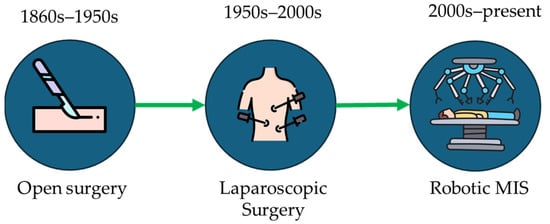
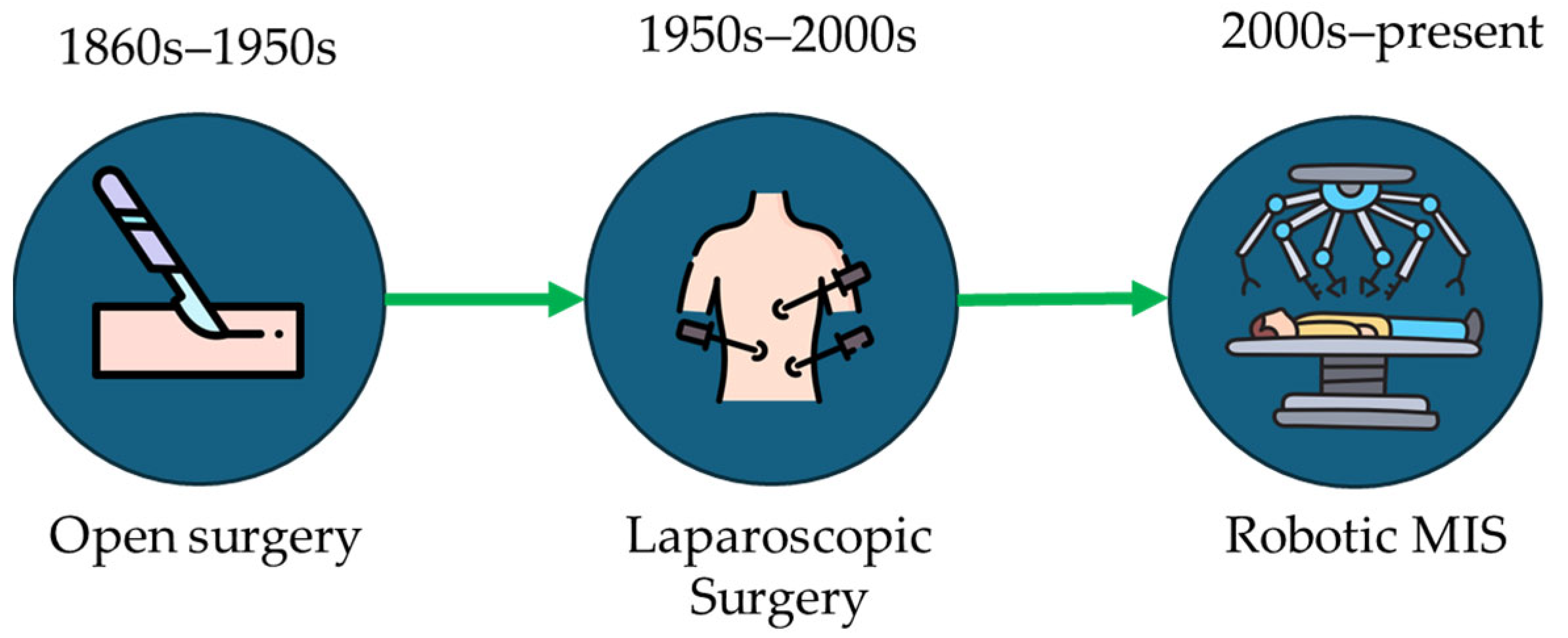
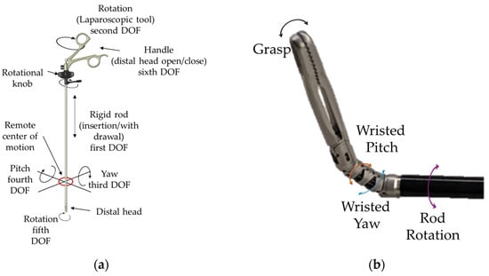
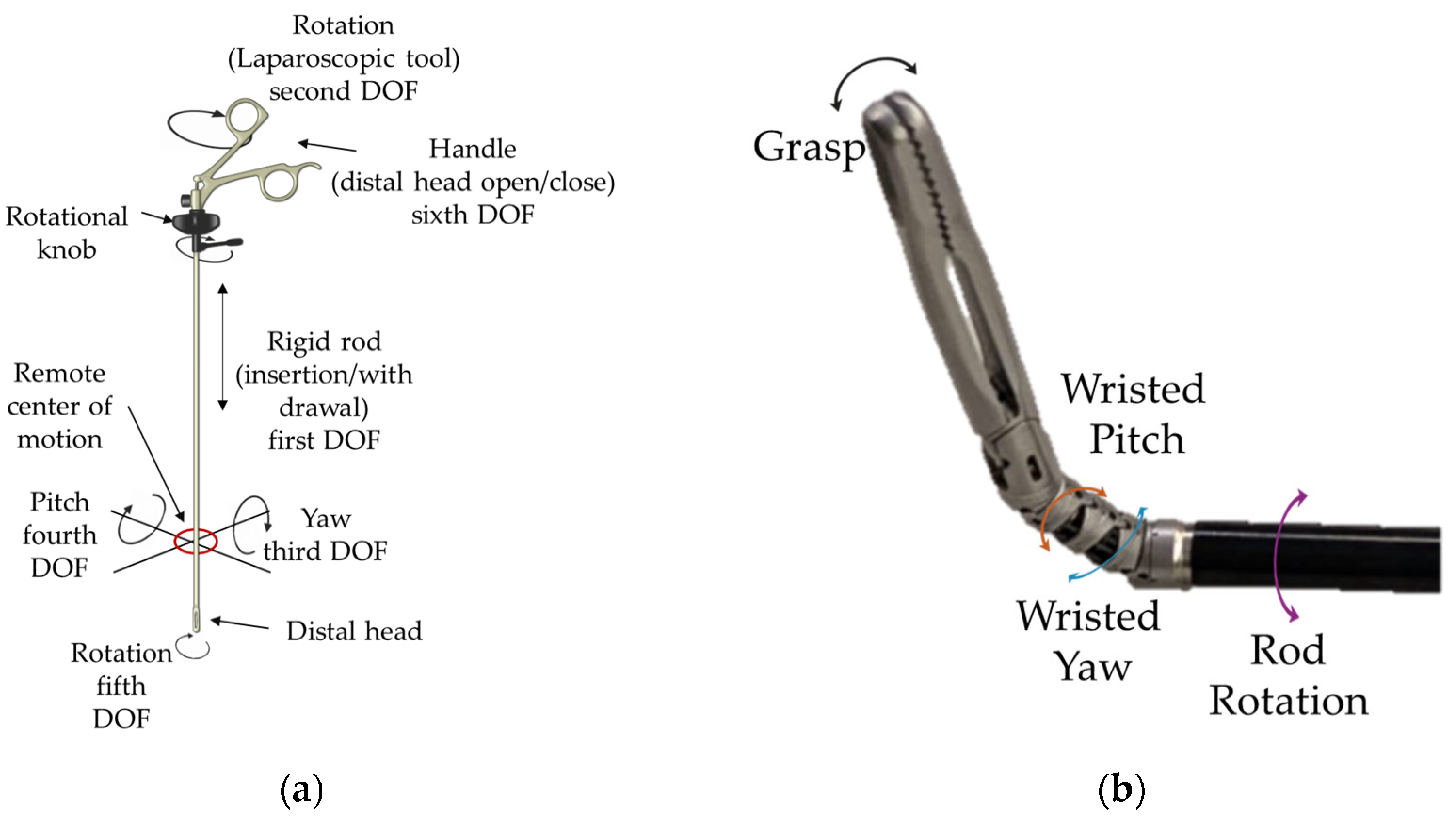
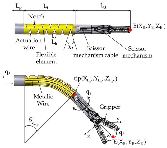
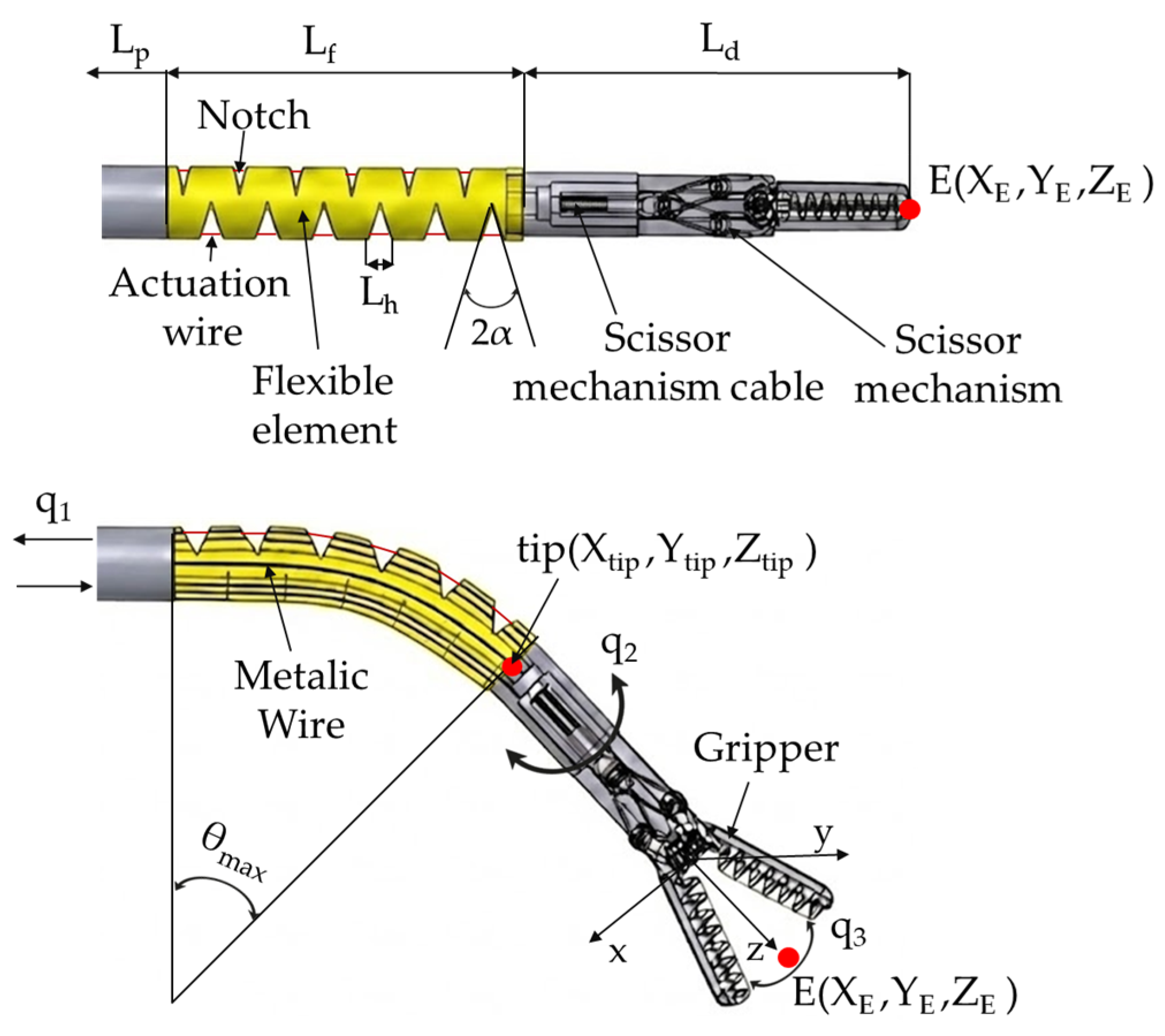
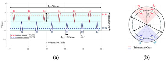
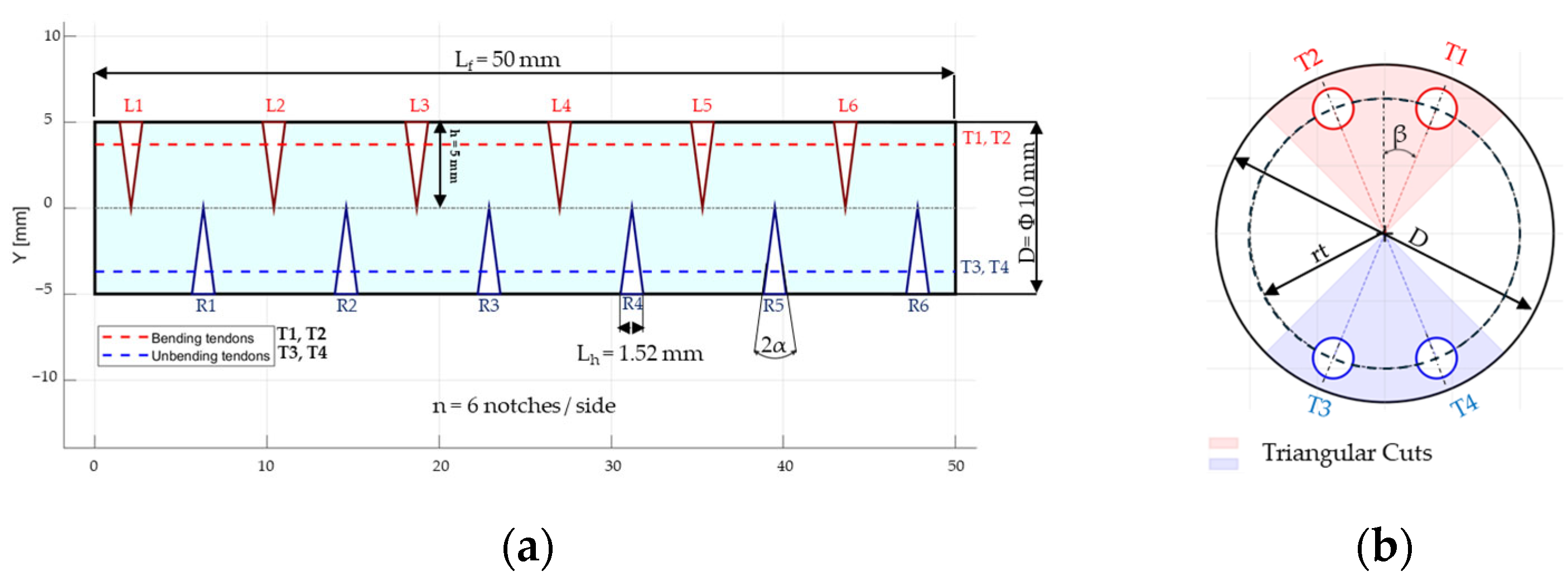
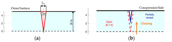
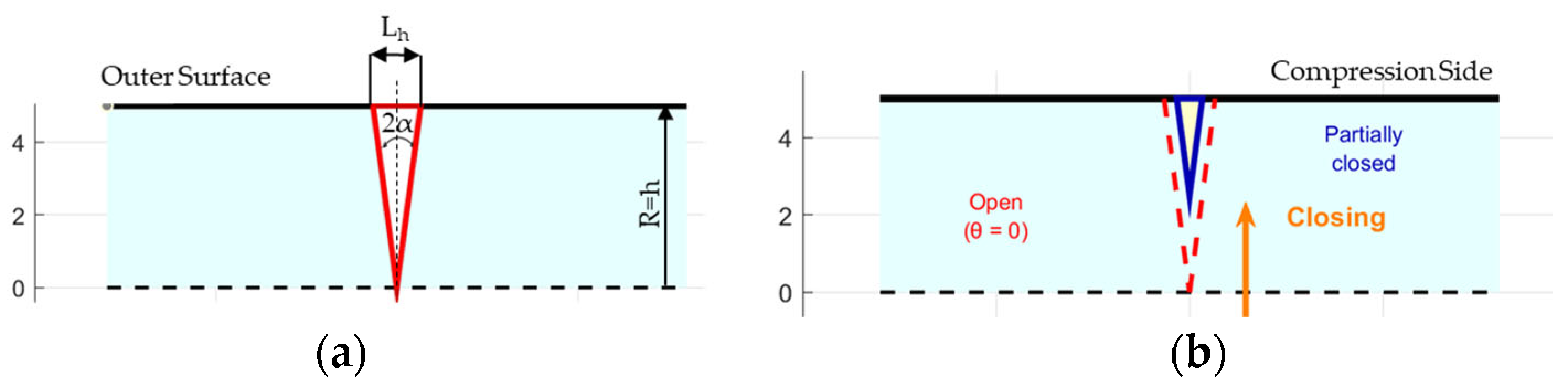
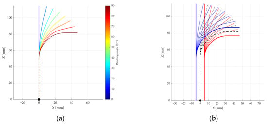
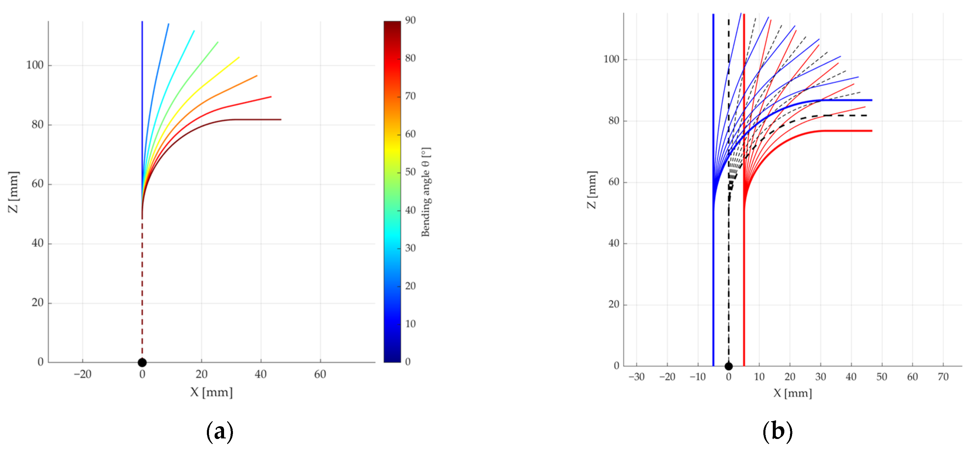
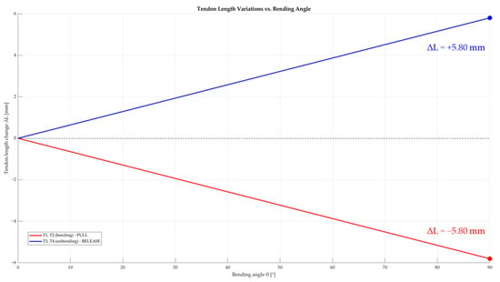
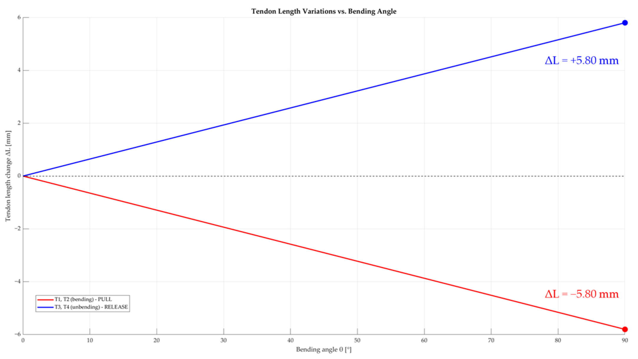
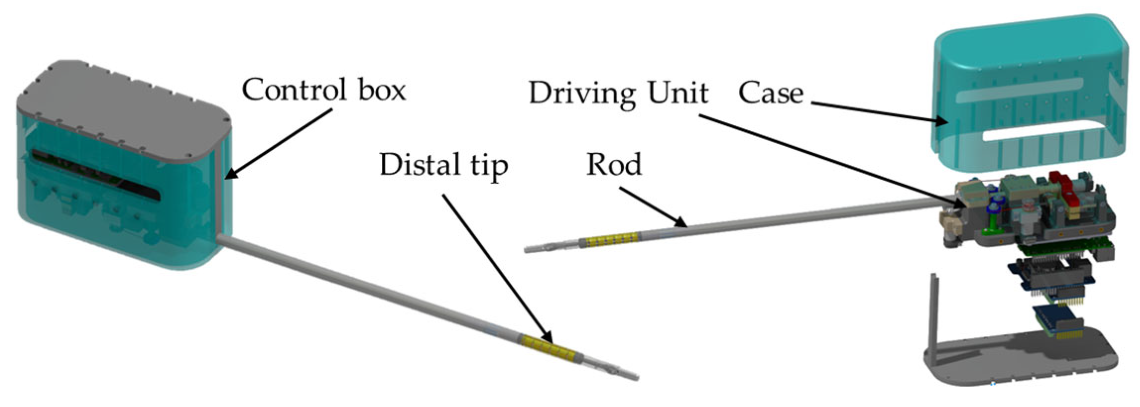
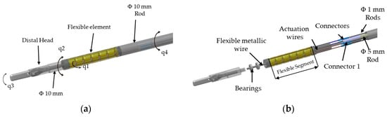
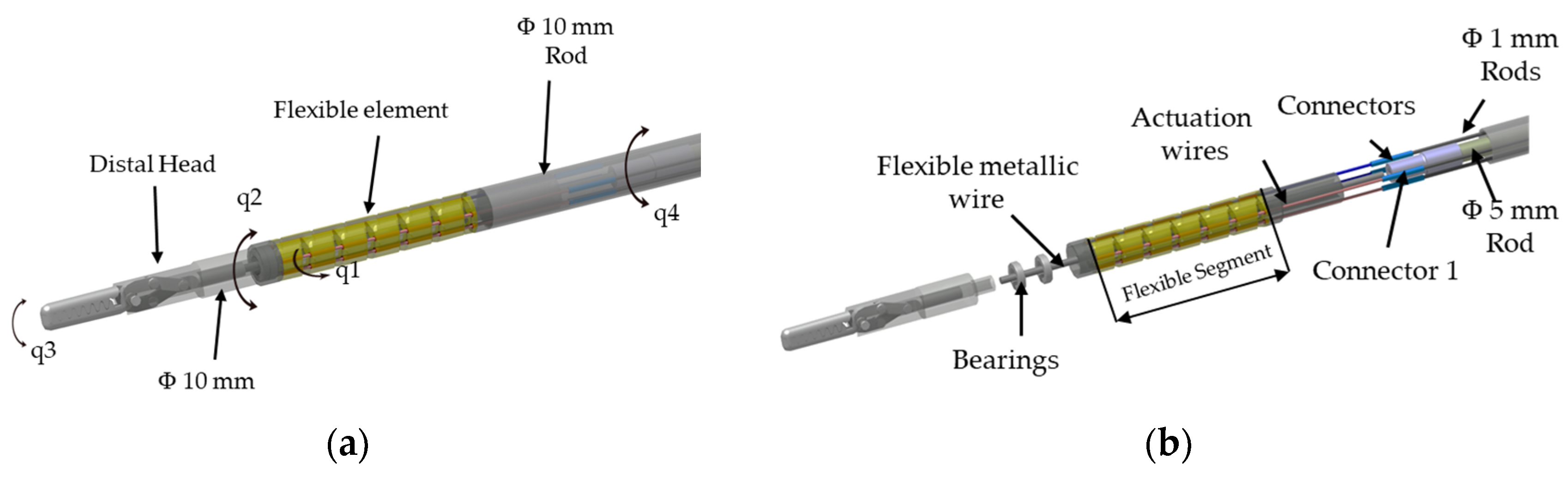
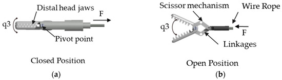
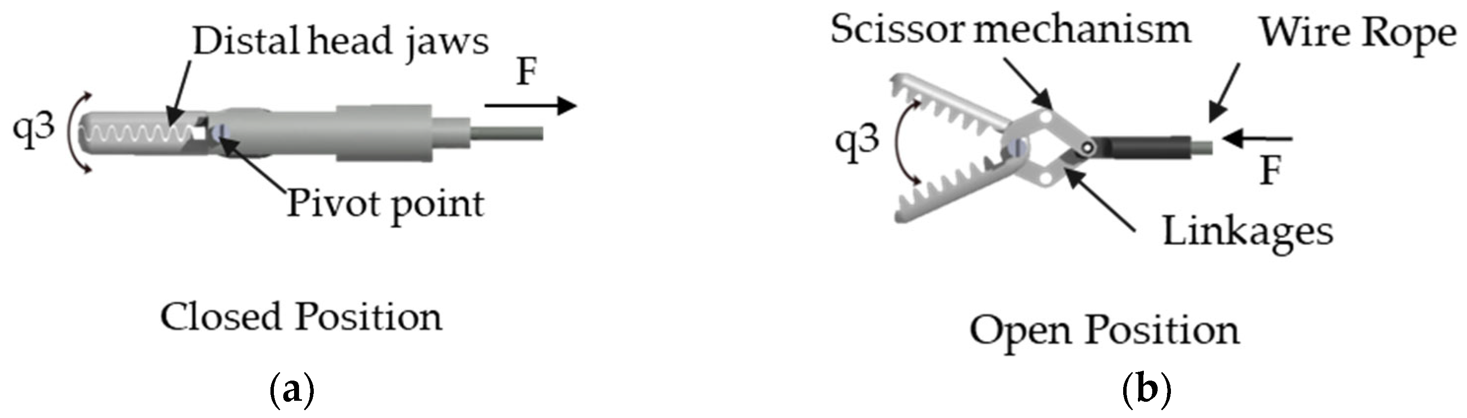
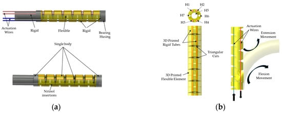
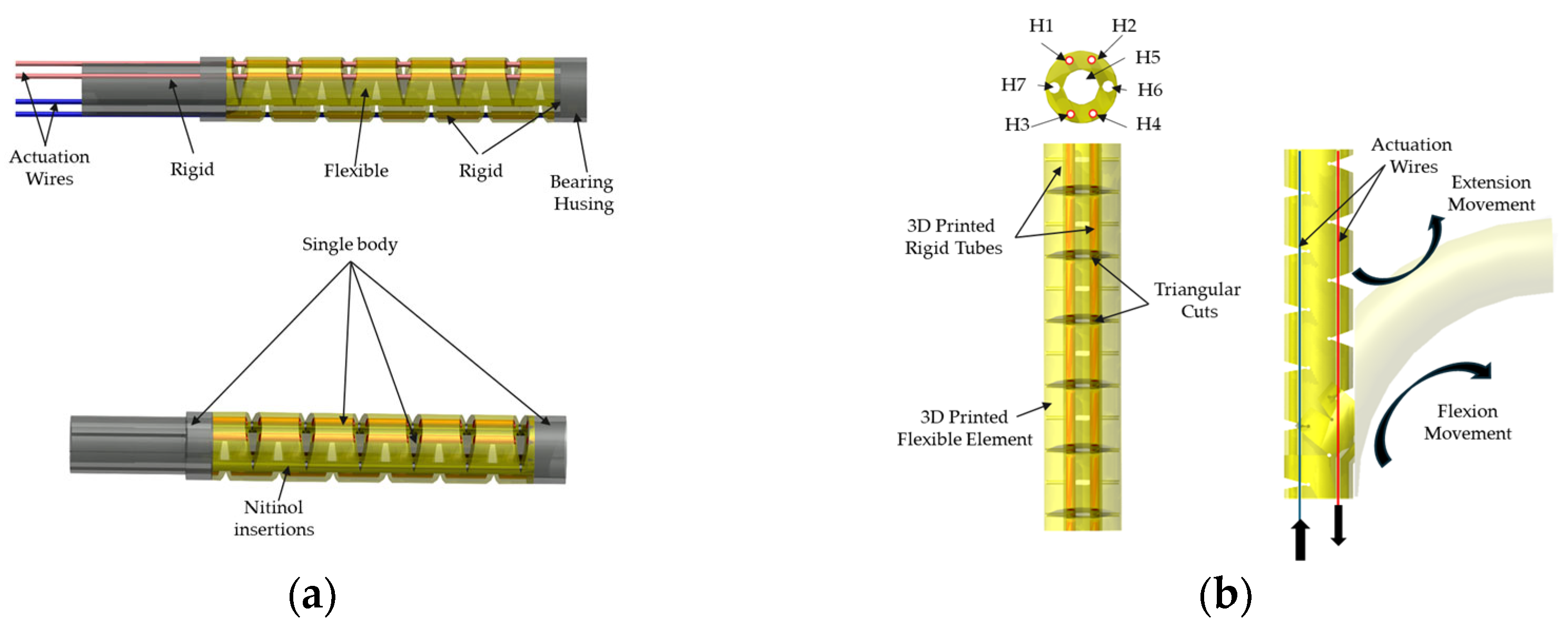
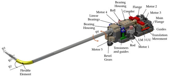
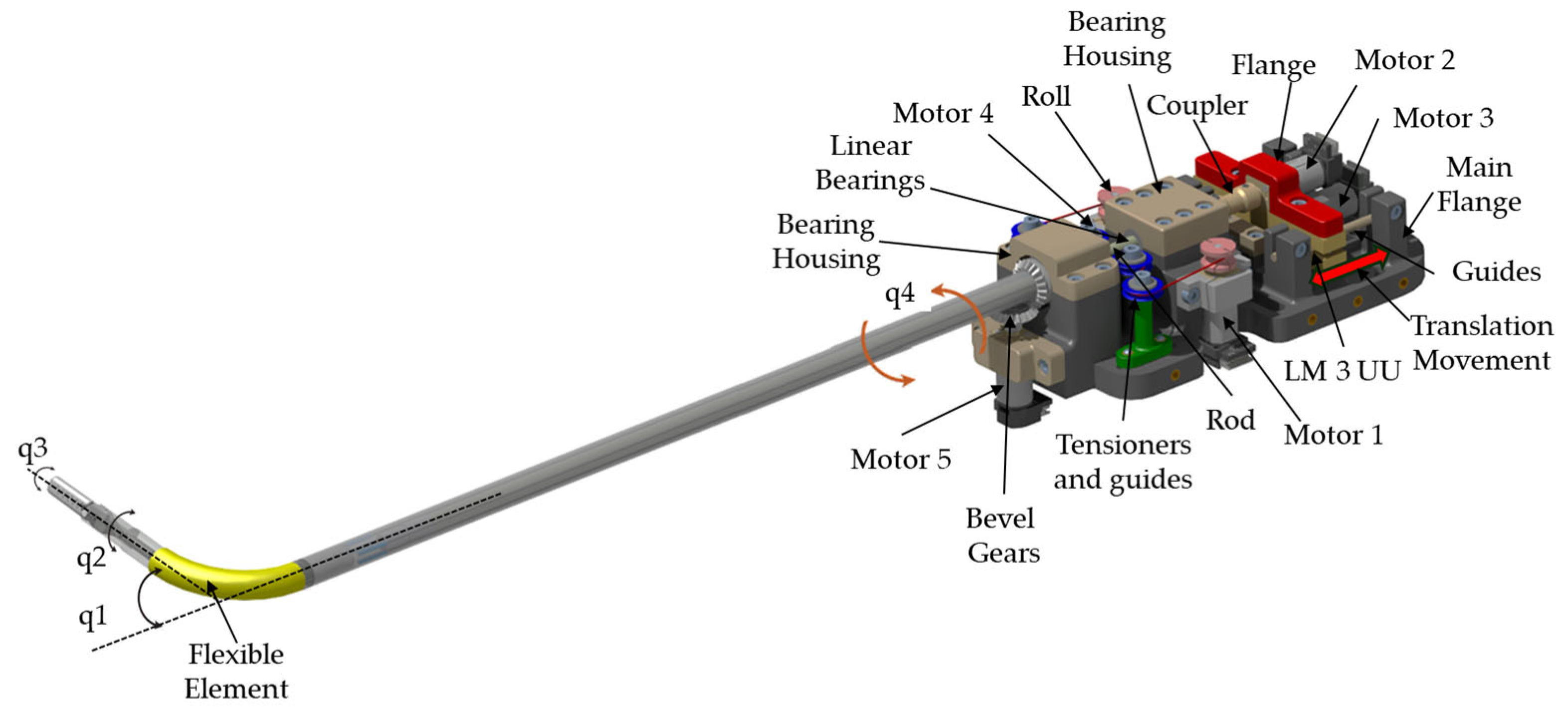
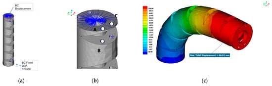
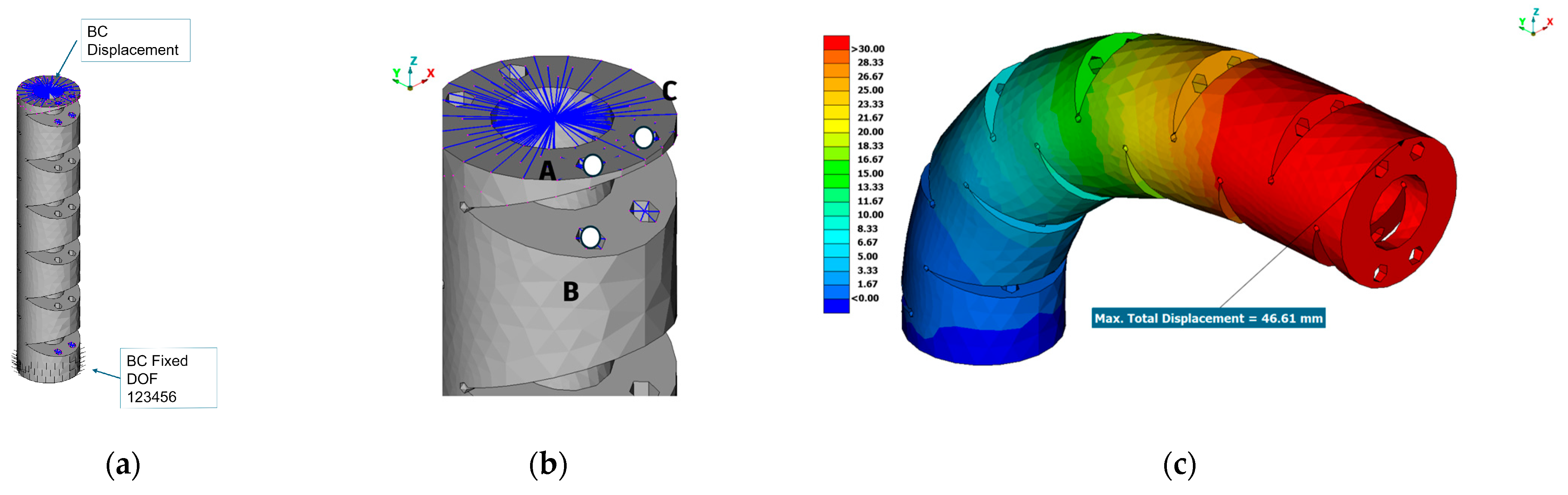
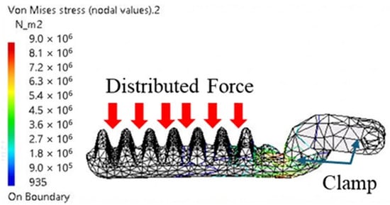
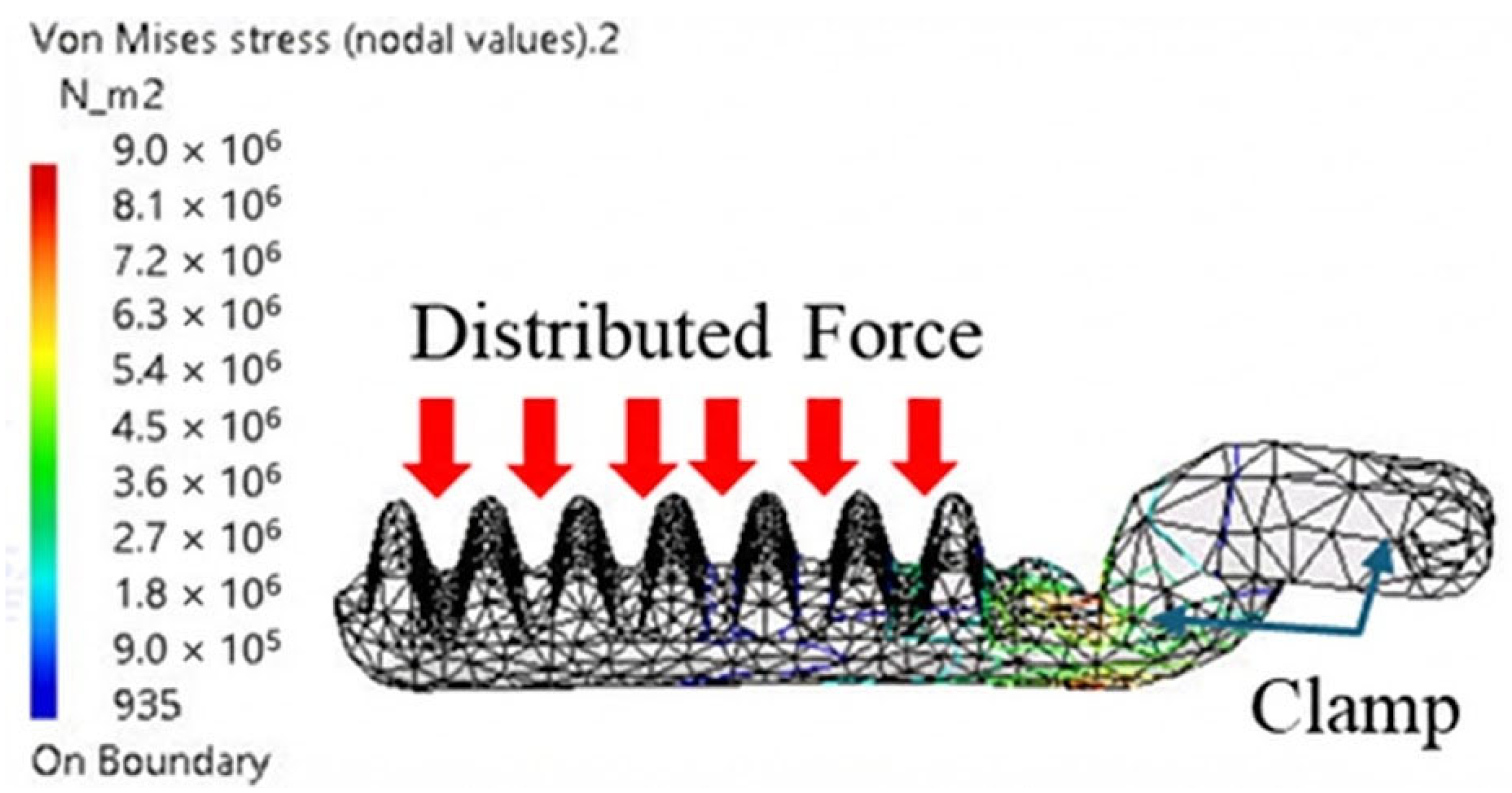




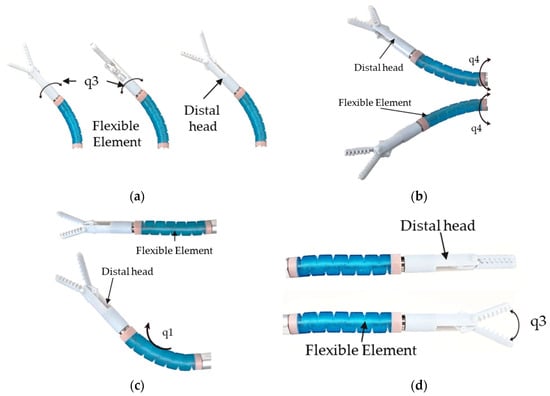
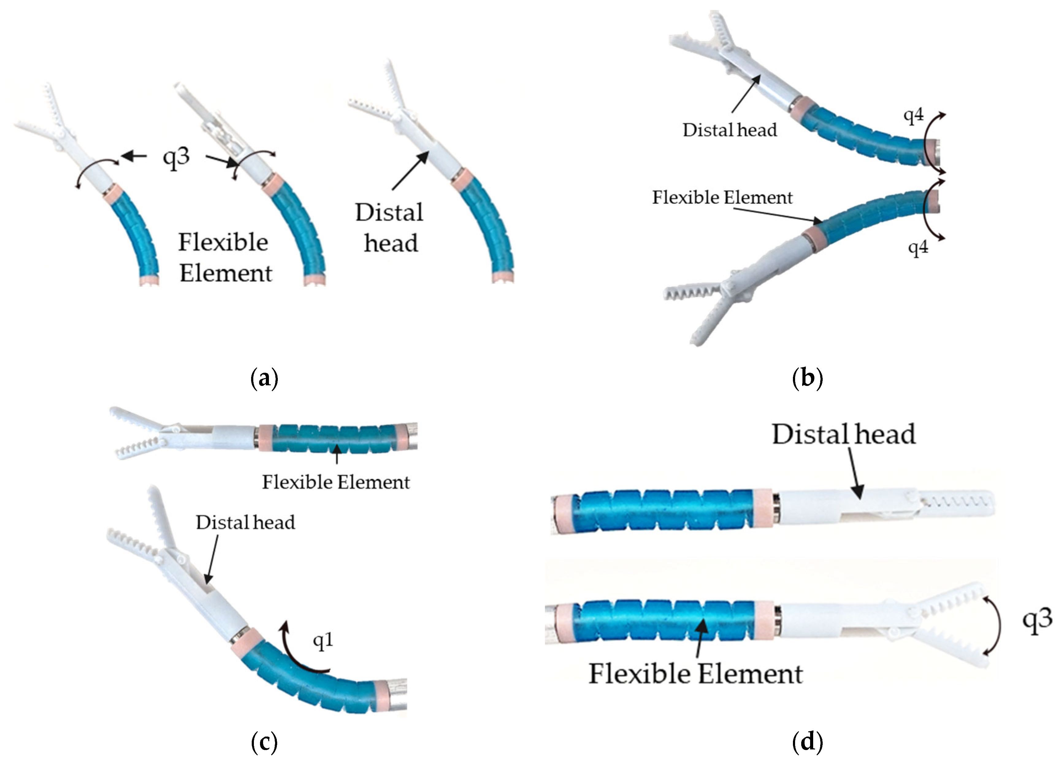
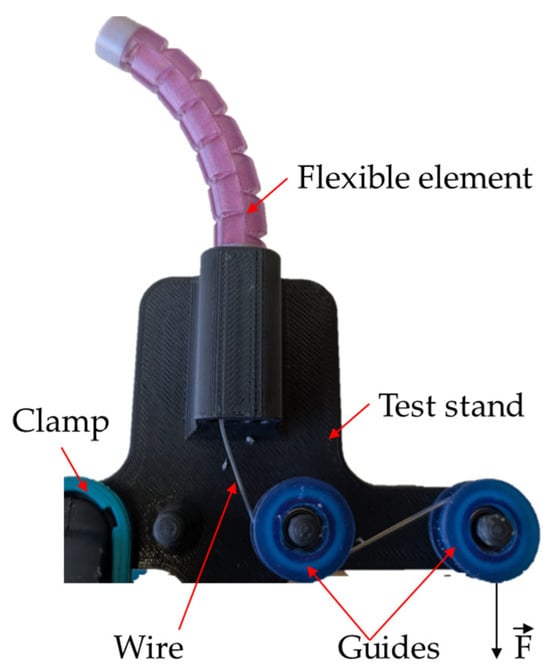
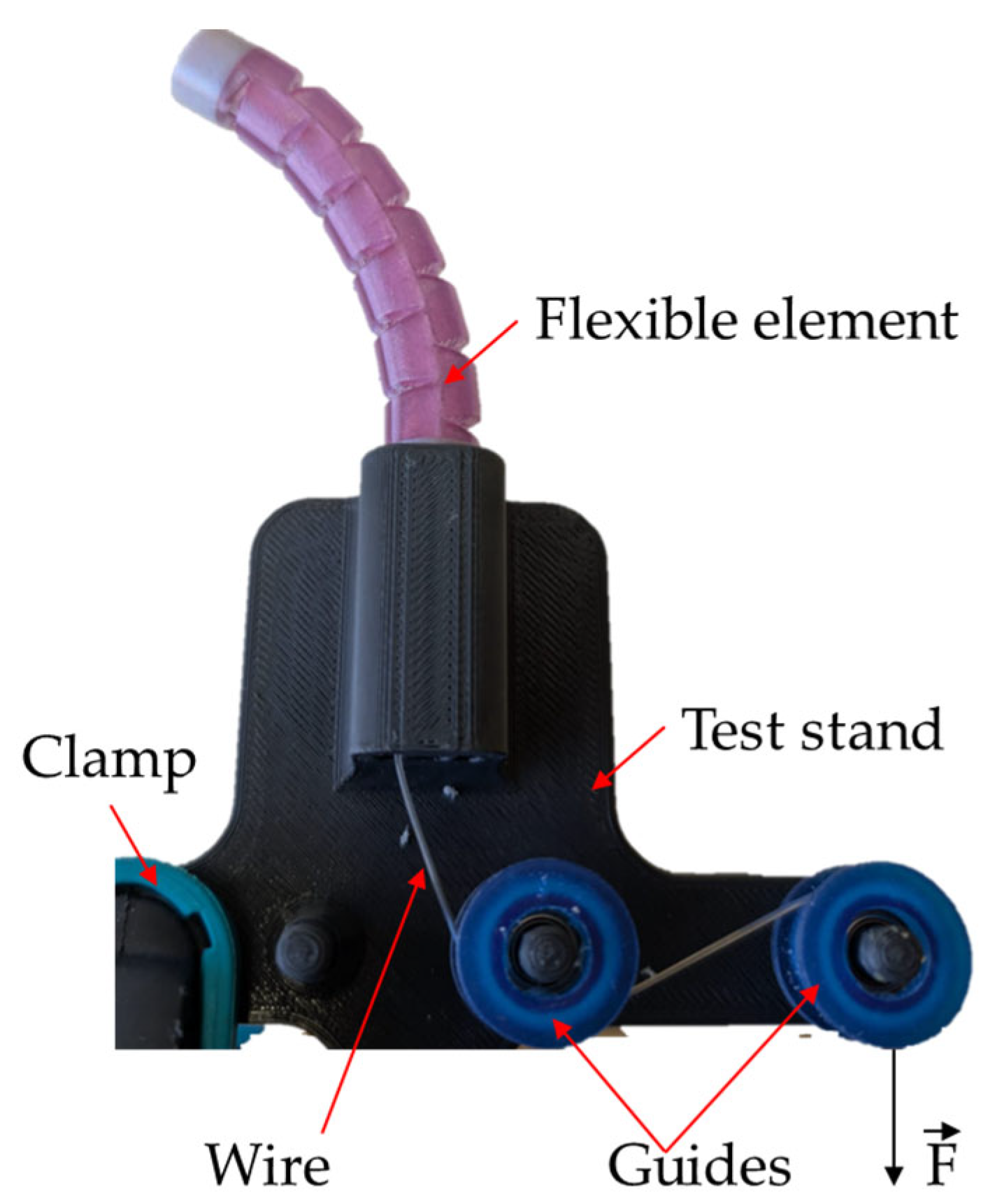
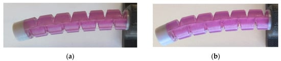
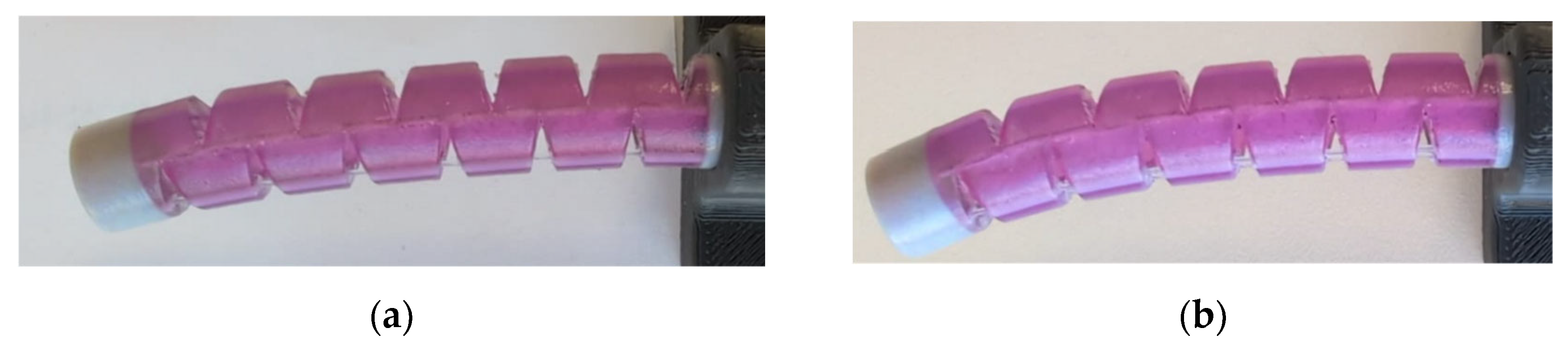
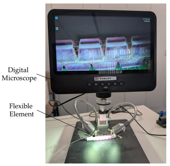
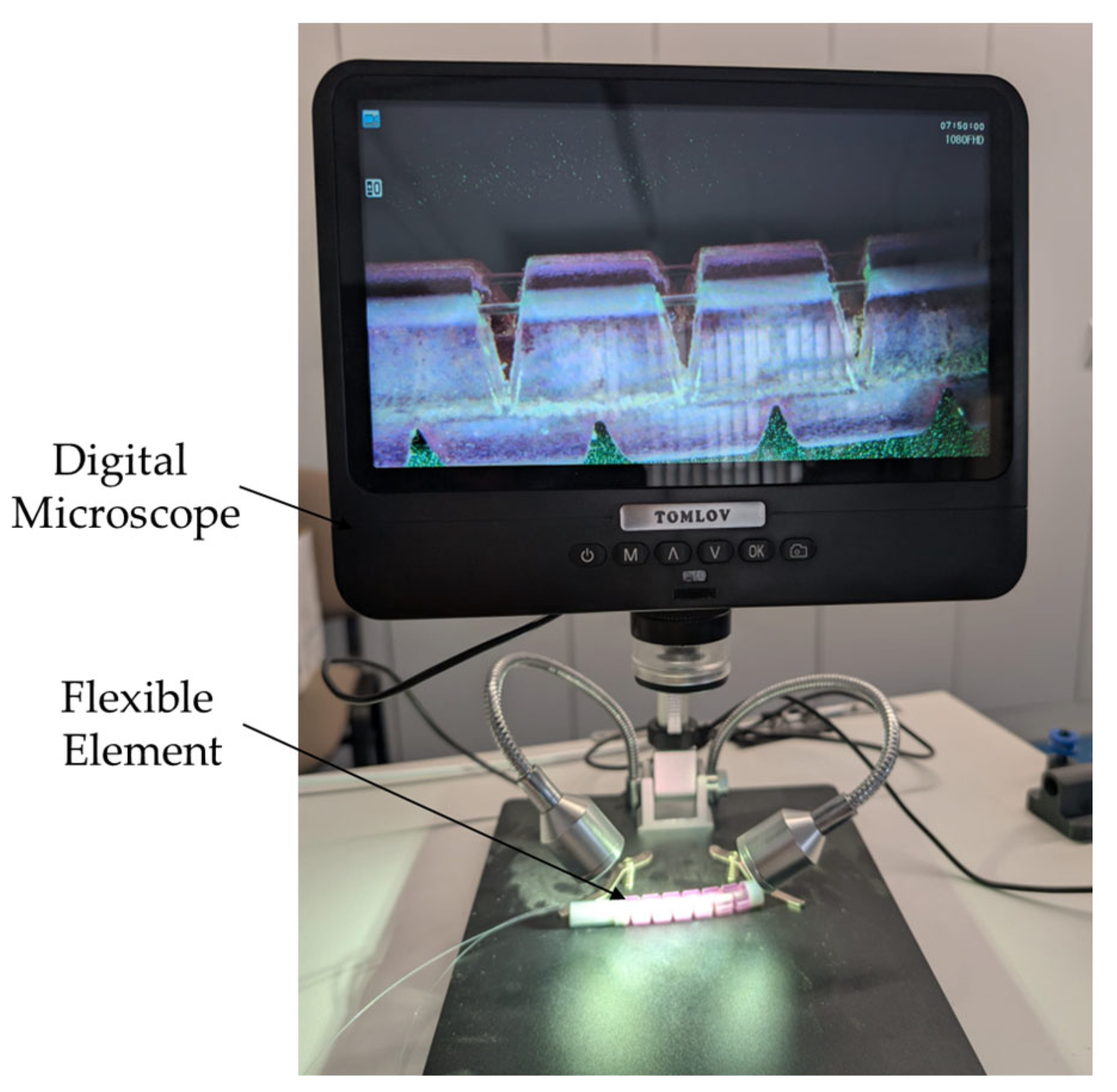
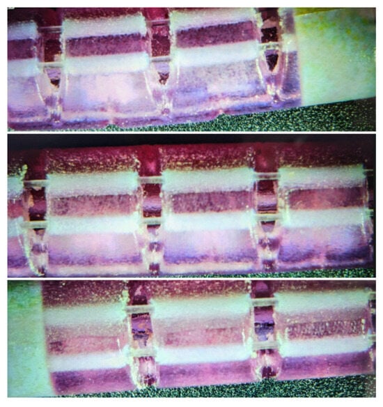
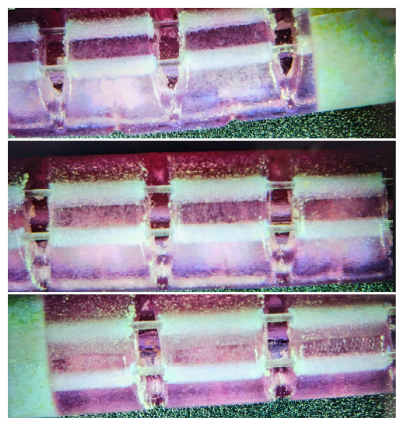
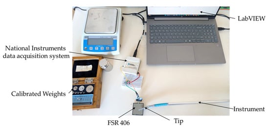
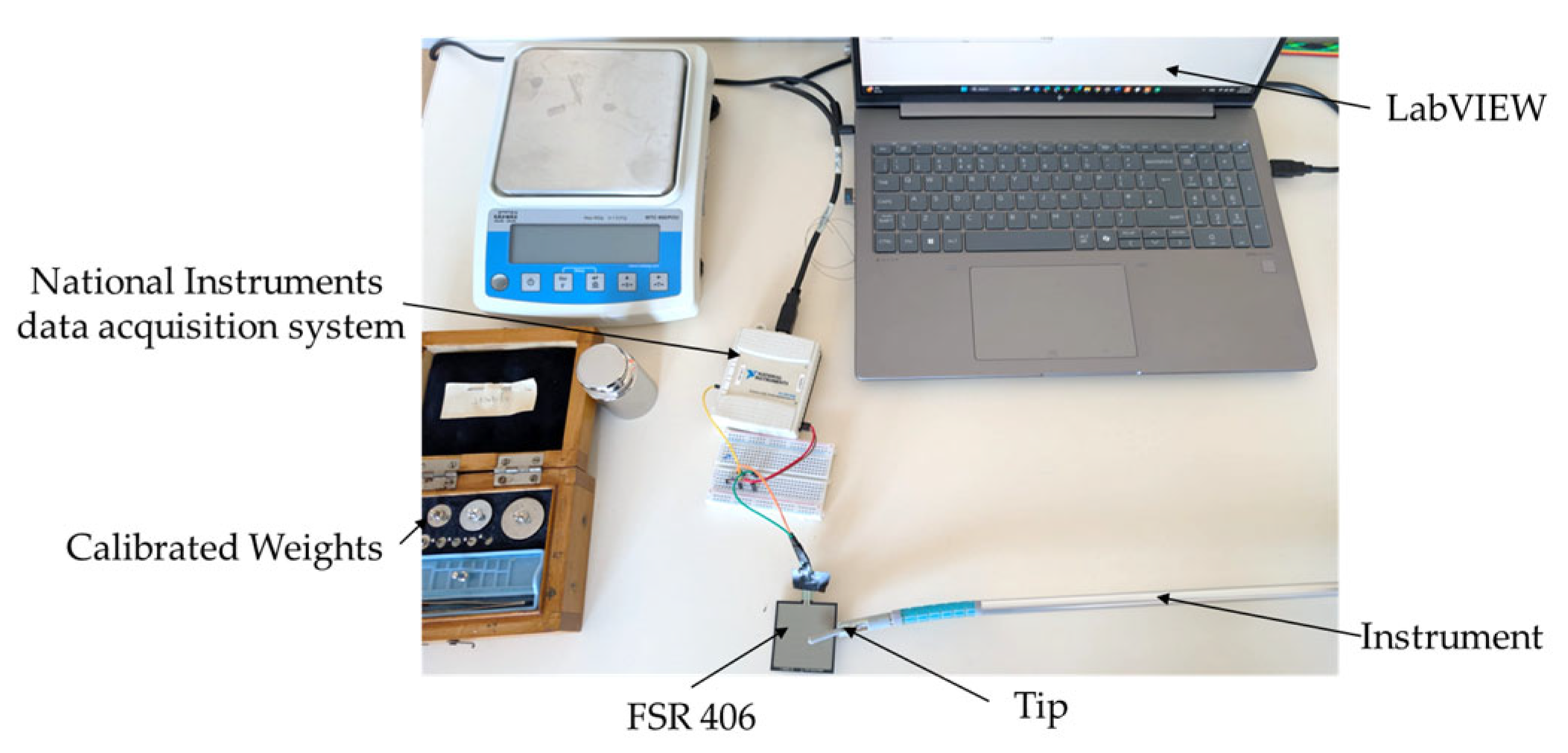
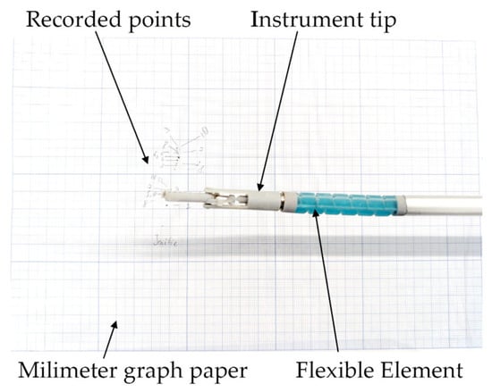
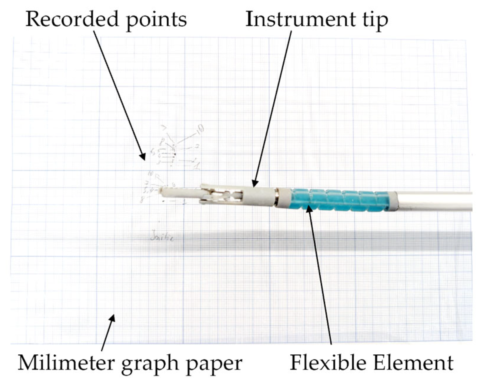
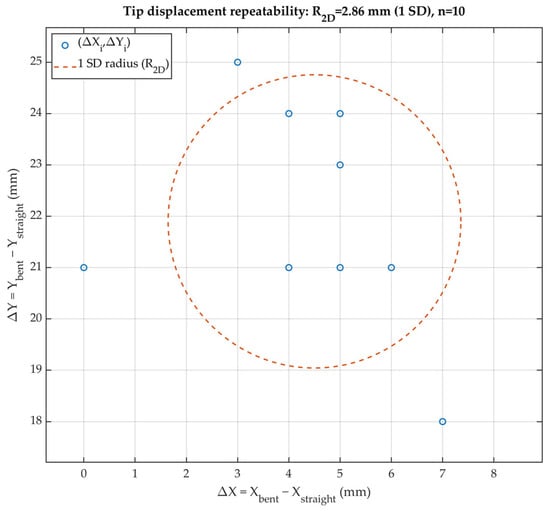
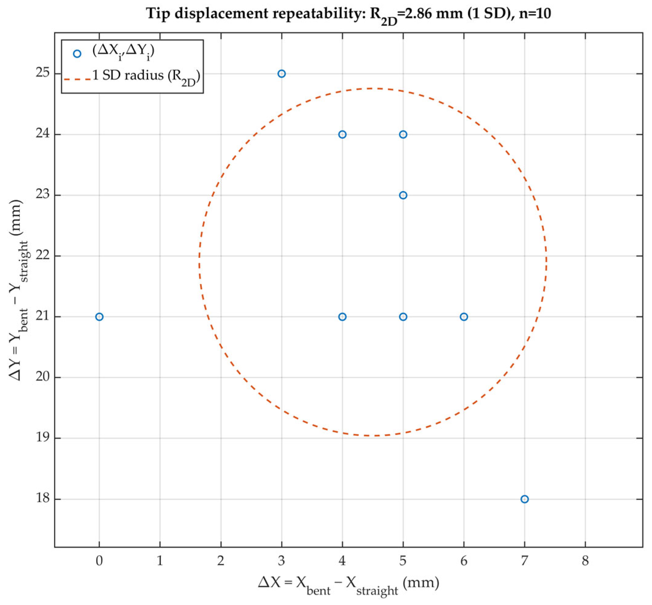
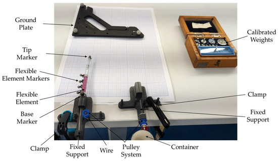
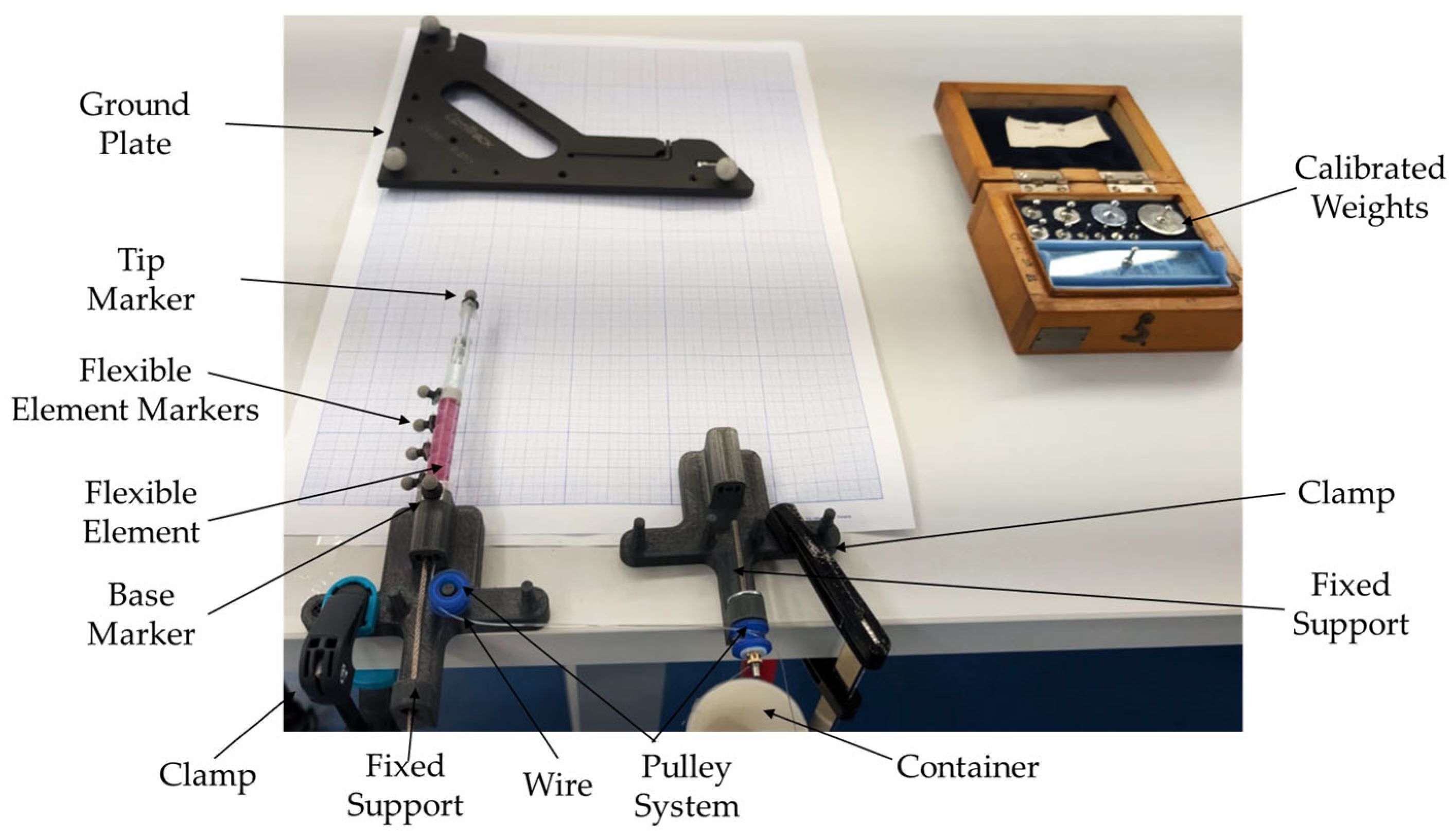
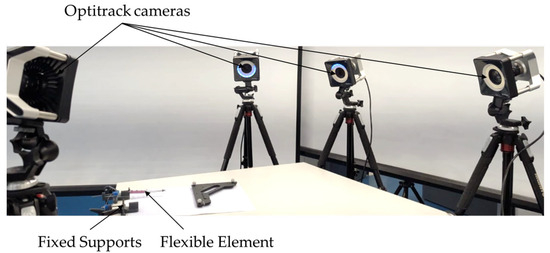
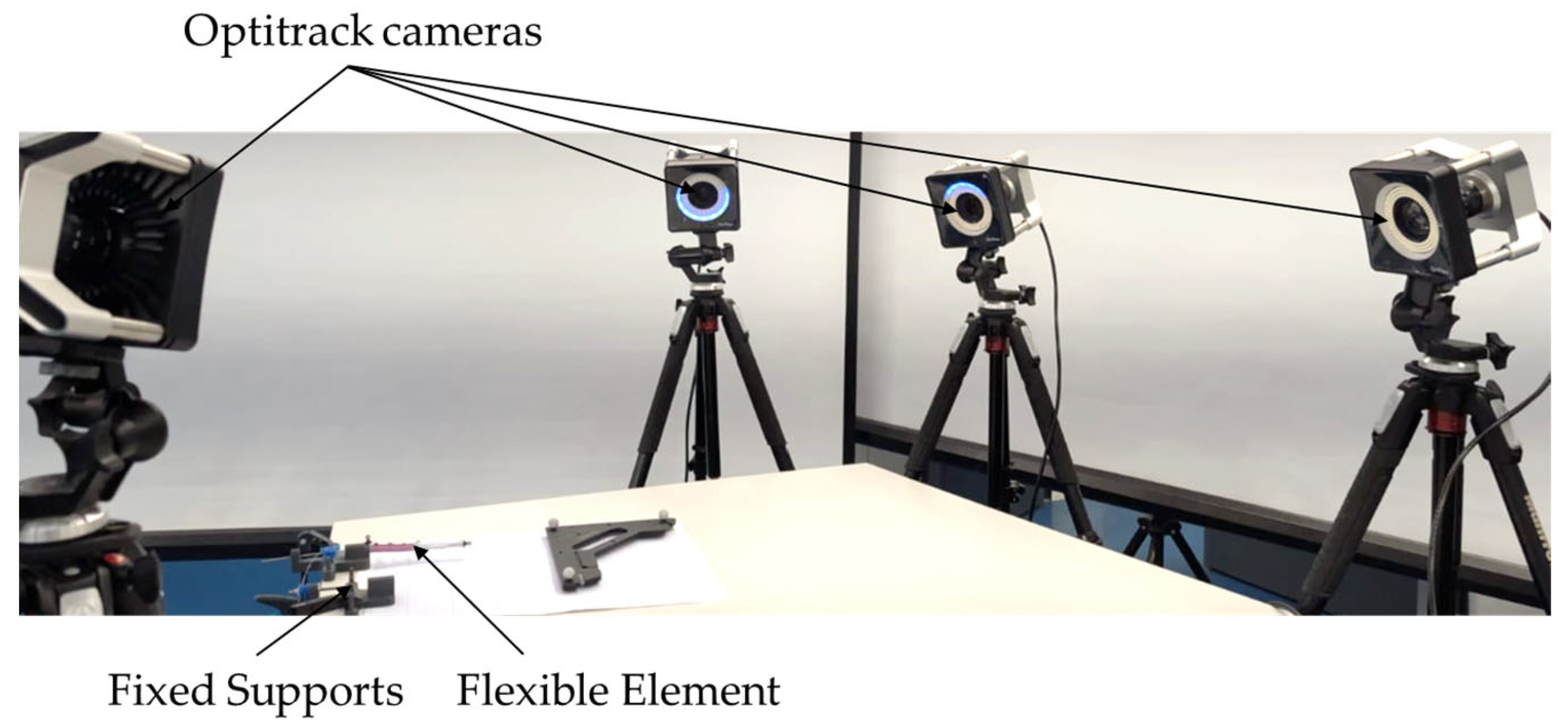
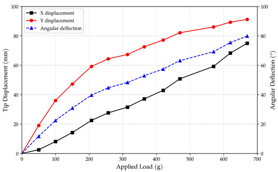
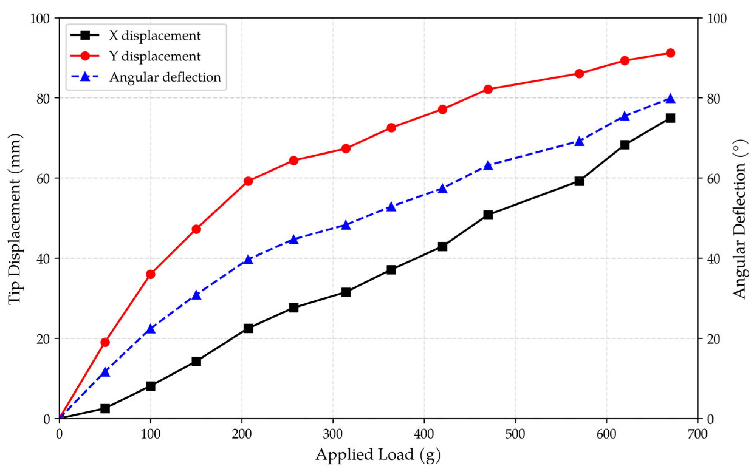
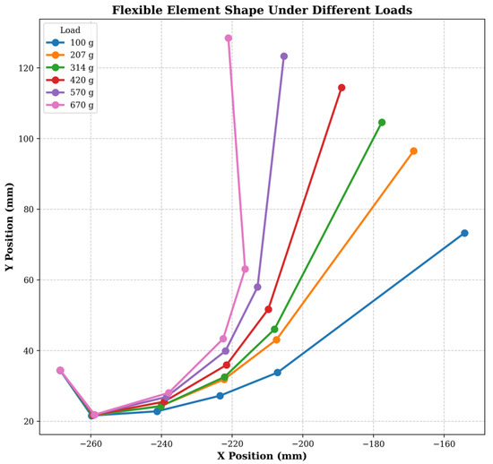
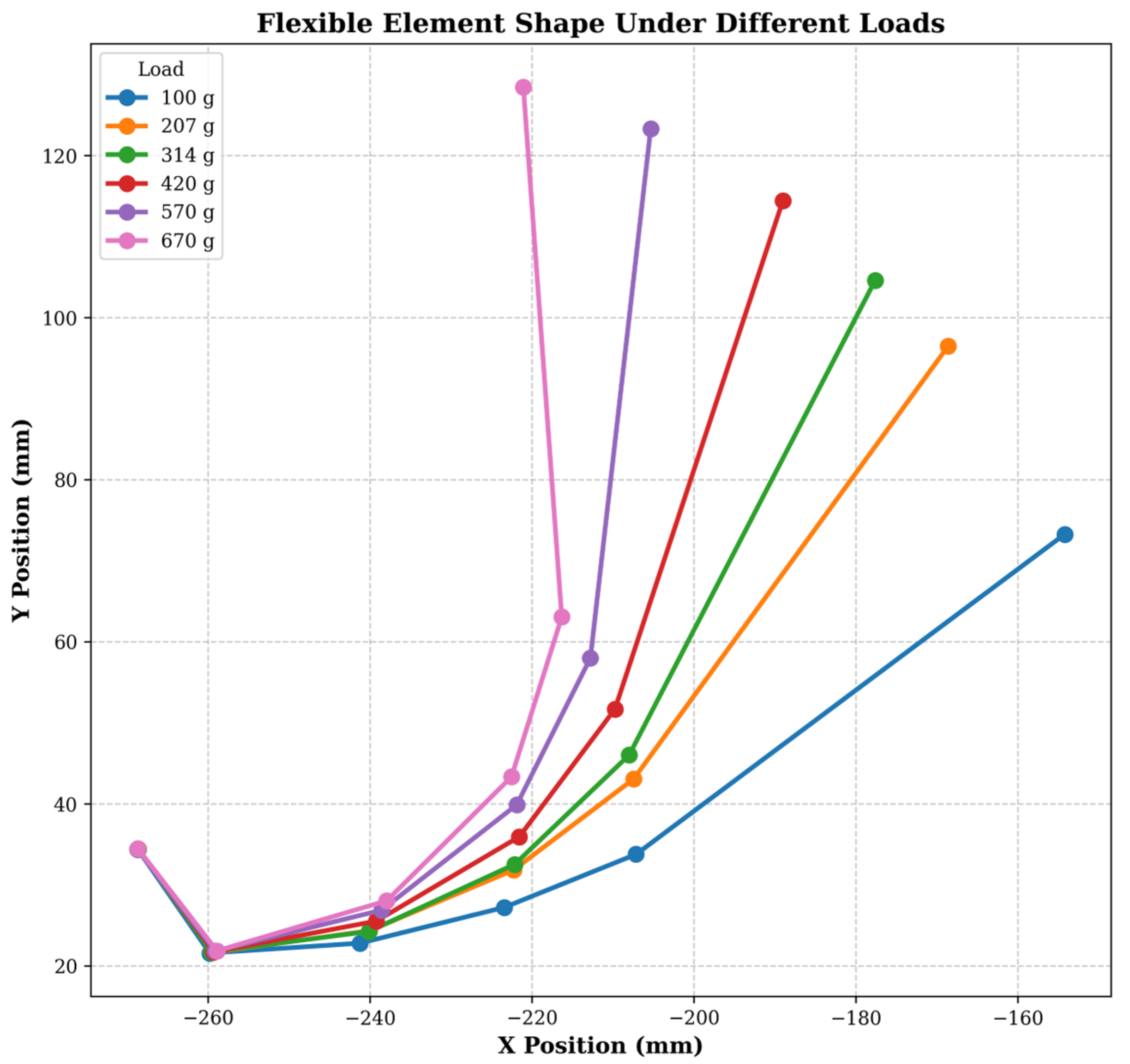
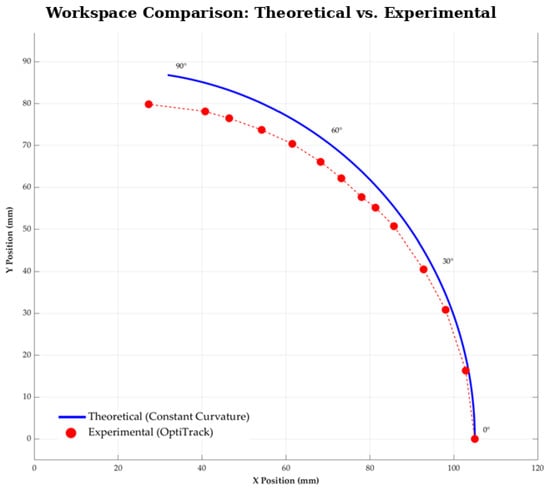
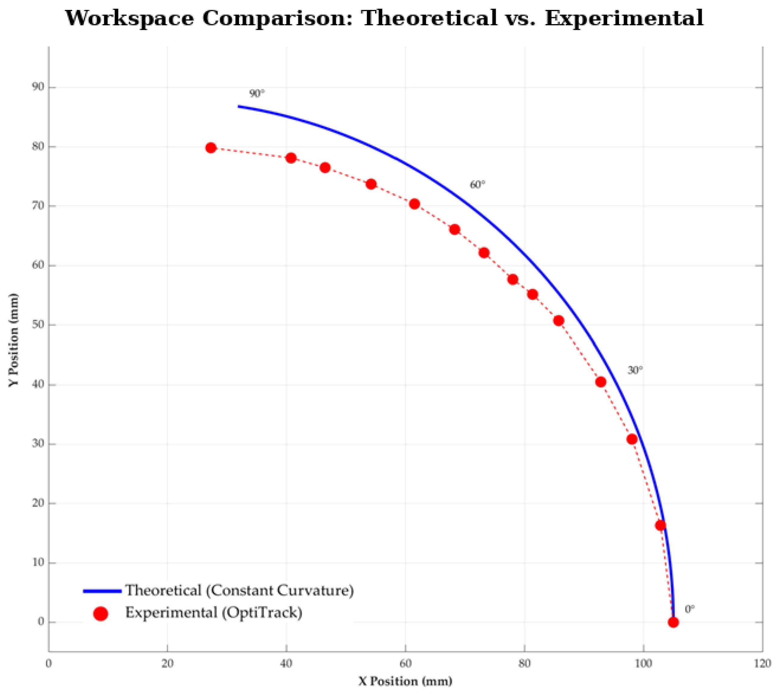
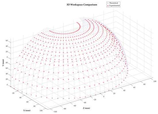
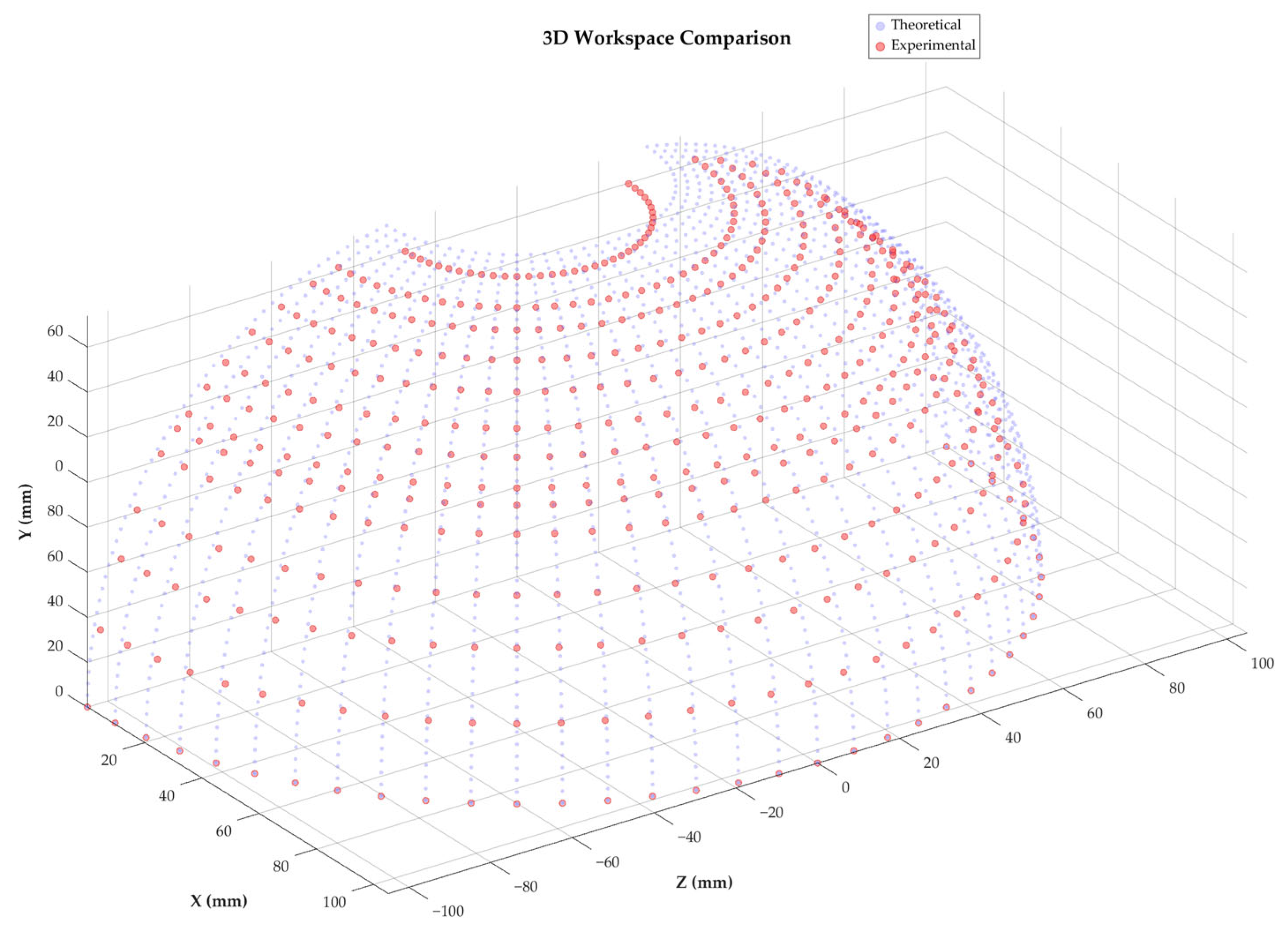
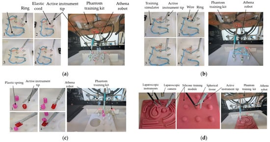
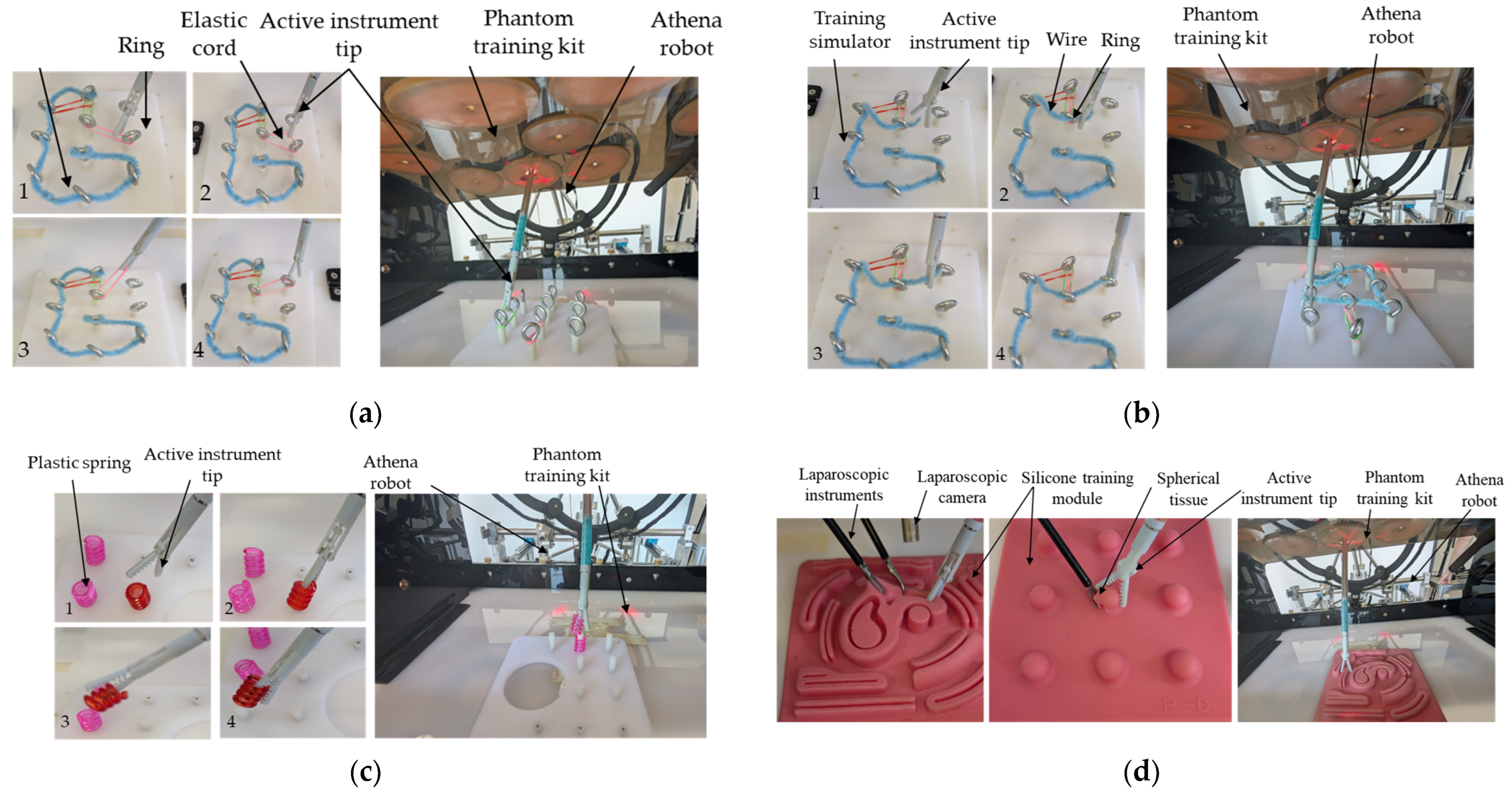
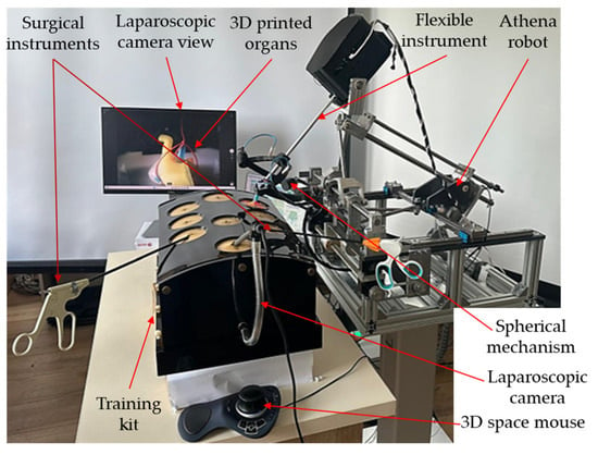
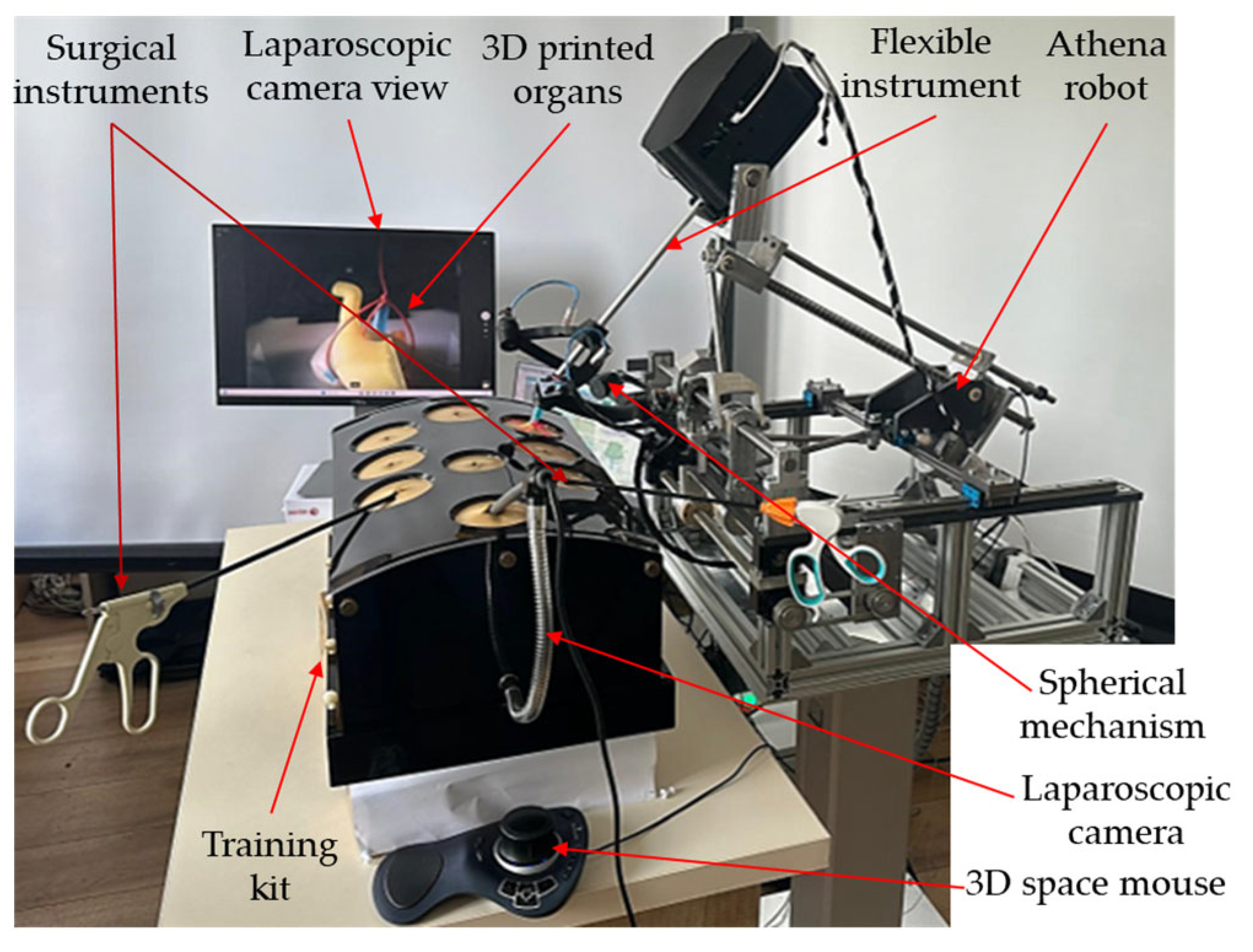
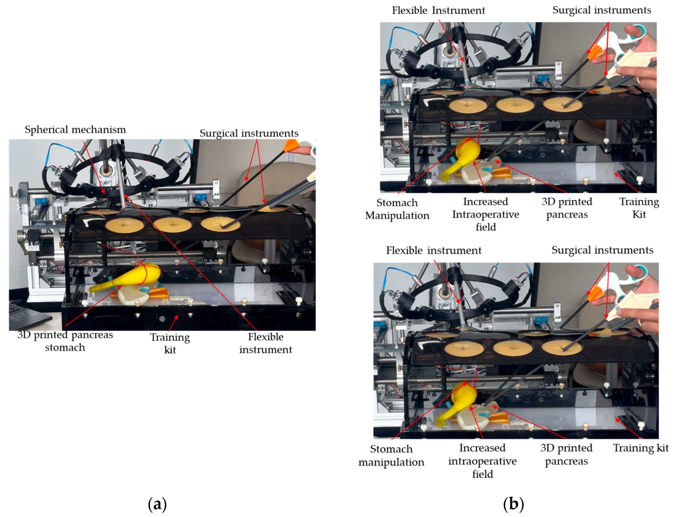

Disclaimer/Publisher’s Note: The statements, opinions and data contained in all publications are solely those of the individual author(s) and contributor(s) and not of MDPI and/or the editor(s). MDPI and/or the editor(s) disclaim responsibility for any injury to people or property resulting from any ideas, methods, instructions or products referred to in the content. |
© 2026 by the authors. Licensee MDPI, Basel, Switzerland. This article is an open access article distributed under the terms and conditions of the Creative Commons Attribution (CC BY) license.