


Abstract
This paper has the goal of exploring the potential of electromagnetic propulsion systems based on tethers to create artificial Sun-synchronous orbits for remote sensing satellites, as well as performing station-keeping maneuvers and de-orbiting of the satellite after the end of its useful life. To create artificial Sun-synchronous orbits, the force is applied to keep the longitude of the ascending node with the same angular velocity of the apparent motion of the Sun around the Earth, which is the definition of a Sun-synchronous orbit. These orbits are very important for remote sensing satellites, because in these orbits the satellite passes by a given point at the same time, helping in analyzing the data collected. The use of electrodynamic tethers can extend the regions of Sun-synchronous orbits, both in terms of inclination and semi-major axis. To perform the de-orbiting of the satellite, the same tether can apply a force in the opposite direction of the motion of the satellite, so reducing its energy and decreasing the semi-major axis until the satellite crashes into the atmosphere of the Earth. This is very important to avoid increasing the presence of space debris in space, a very serious problem nowadays. For the station-keeping maneuvers, we just need to use the appropriate control laws, from time to time, to correct any errors in the Keplerian elements. A significant advantage of employing an electrodynamic tether over traditional thrusters is that it does not require consumption of fuel. The study assumes that a current can flow in both directions through the tether, so interacting with the magnetic field of the Earth to create the Lorentz force. The possibility of using electrodynamic tethers with autonomous charge generation, to avoid dependence on plasma densities and other external factors, is considered. The results presented here help in space and planetary science, since they give more options for remote sensing satellites, which are a key element in planetary science.
1. Introduction
Sun-synchronous orbits (SSOs) are crucial for various applications in planetary and space science. They allow satellites to pass over the same points on Earth at approximately the same local solar time, providing consistent lighting conditions, which is essential for imaging and monitoring applications like agriculture, forestry, and environmental studies. By maintaining similar Sun angles during each pass, SSOs improve the quality and comparability of images over time, reducing variations in shadows and lighting. This is particularly important for land cover classification and change detections. These orbits provide regular and predictable coverage, which is beneficial for time-sensitive applications such as disaster response, weather monitoring, and climate studies.
Many remote sensing satellites (Li et al., 2023 [1]) are placed in SSOs to optimize their effectiveness in capturing data related to surface features, vegetation health, and urban development. They support scientific research by providing consistent observational conditions, vital for long-term studies in meteorology, oceanography, and climatology. SSOs facilitate coordination between multiple satellites in the same orbital plane, allowing better data integration and analysis of different missions. By maximizing the efficiency of data collection and minimizing the need for multiple satellites to cover the same areas, these orbits can reduce operational costs for agencies and organizations involved in Earth observation.
Achieving and maintaining Sun-synchronous orbits involves careful planning and precise orbital mechanics. To enter an orbit of this type a satellite is typically launched into a near-polar orbit, meaning that it travels near the Earth’s poles. The launch vehicle must achieve a specific inclination, usually between 97° and 101°, to ensure the orbital plane precesses with the same angular velocity of the Earth’s rotation around the Sun. For this, the non-spherical shape of the Earth is used to perturb the Keplerian motion of the satellite. Once in orbit, maintaining an SSO requires adjustments to compensate for perturbations, which can change the satellite’s orbital plane, gradually shifting it away from the desired Sun-synchronous condition.
So, to reach a Sun-synchronous orbit requires the satellite to have precise orbital elements to make sure that the satellite’s orbital plane precesses in alignment with the Sun. The inclination, semi-major axis and eccentricity must follow a relation exactly to achieve the desired precession rate. This relation is usually based on dynamics that consider the Keplerian gravity field and the flattening of the Earth. If we add extra forces, the relation between the inclination, semi-major axis and eccentricity of the orbit must follow a slightly different relation, so generating different Sun-synchronous orbits.
Some studies available in the literature show that extra forces can be used to generate so-called “artificial Sun-synchronous orbits” (Wu, Jiang and Li, 2015 [2]; Macdonald, McKay, Vasile and Frescheville, 2010 [3] and Masoud, Rahoma, Khattab and El-Salam, 2019 [4]), which give more flexibility to mission designers to attend to some other requirements of the mission by having more choices for the combination of the orbital elements of the orbit. The main idea is to use some type of low propulsion to complete the effects of the flattening of the Earth to keep the Sun-synchronous conditions without following the relations for the orbital parameters that give natural Sun-synchronous conditions.
In that sense, a new possible alternative that has not been explored before in the literature is the use of electrodynamic tethers to create artificial Sun-synchronous orbits. Exploring artificial SSOs using electrodynamic tethers presents potential benefits. These tethers generate thrust through interactions with the Earth’s magnetic field, offering a propellant-free method for maintaining and adjusting orbits. By applying controlled currents through the tether, satellites can adjust their velocity and trajectory, effectively maintaining the precise conditions required for Sun-synchronous orbits without relying on traditional propulsion systems. The use of electrodynamic tethers reduces the need for onboard fuel, extending the satellite’s operational life and lowering costs. This proposed approach increases the feasibility of long-term missions and could enable more sustainable and efficient management of satellite constellations in Sun-synchronous orbits. Of course, it is necessary to include the tether in the spacecraft, but a mechanism like this can be used for station keeping and de-orbiting the spacecraft, so this multiple use may make this option viable for some missions.
Electrodynamic tethers have gained significant interest for their potential in space applications (Xie, 2021 [5]). Hoyt and Forward (1989) [6] explored the autonomous de-orbiting of LEO spacecraft, providing insights into tether dynamics. Yamagiwa (1997) [7] analyzed tether orbit transfer systems for round-trip missions, demonstrating their versatility in maneuvering. Johnson and Herrmann (1998) [8] worked on the International Space Station’s electrodynamic tether reboost system, which was a practical application for station keeping. After that, Santangelo et al. (1999) [9] advanced tethers towards commercially viable systems. Gilchrist, Johnson and Bilen (1999) [10] discussed system considerations and future plans for tether propulsion technology, paving the way for further advancements. Lanoix, Misra, Modi and Tyc (1999) [11] studied in detail the dynamics of electromagnetic tethers in satellites. Vas, Kelly, and Scarl (2000) [12] explored space station reboosting using tethers, emphasizing their utility in maintaining orbital positions. PelKaez, Lopez-Rebollal and Ahedo (2002) [13] examined the dynamic stability of bare tethers as de-orbiting devices, while PelKaez, Lopez-Rebollal, and Lorenzini (2001) [14] focused on damping in rigid tethers in inclined orbits, increasing the understanding of tether dynamics under varied conditions. More recently, Valmorbida et al. (2022) [15] performed studies to validate technologies to de-orbit a satellite with the use of electrodynamic tethers, which is closely connected with the present research. After that, Li, Yang, Li and Yao (2023) [16] expanded the knowledge of multitether systems through dynamic modeling and analysis. Sánchez-Arriaga, Lorenzini, and Bilén (2024) [17] reviewed electrodynamic tether missions, identifying historical trends and new market opportunities, demonstrating the growing role of tethers in satellite operations and future space missions. Following this line of research, Slavinskis and Janhunen (2024) [18] worked on the use of tethers for CubeSat sails.
Most of the studies done on electrodynamic tethers use electrons available in space to create the current along the tether. Of course, this is an interesting idea, but it gives some limits in terms of the current available, which decreases with the altitude of the orbit, since the density of electrons reduces with the distance from the Earth. It also brings problems related to sheath effects and the feasibility of bidirectional current flow. An alternative is to use an onboard battery that can be controlled by the satellite, giving the possibility of larger currents, independent of the density of the plasma, and easier control over the direction of the flow. Of course, this decision depends on the specific mission. This research only focuses on the dynamics of the system, showing the possibilities that this technique can give for different values of the variables involved. More details about this will be given later in this research.
Another point studied related to tethers in the literature is a maneuver based on using a tether on one or more satellites and then cutting the tether to release the satellites. It is like applying an impulsive maneuver to the satellites. Examples of this type of research can be found in Salazar, De Almeida Prado and De Moraes (2025) [19] and Prado, Razoumny and Santos (2025) [20]. In those situations it is important to consider the problem of chaotic motion, as in Salazar and Prado (2021) [21].
In this framework, the present paper has the goal of proposing an electrodynamic tether as an extra force that, combined with the gravity field of the Earth (modeled by the Keplerian term and J2), can be used to create artificial Sun-synchronous orbits. The results will show that we have Sun-synchronous orbits with a larger semi-major axis compared to the natural ones, with a semi-major axis of 20,000 km or even more, which is not possible without the use of some type of propulsion. After this, the present research will show that it is possible to use the same tether to perform station-keeping maneuvers and to de-orbit the spacecraft, just by changing the law that the current should follow when passing through the tether.
In particular, the present study shows that this technique is better when used in small satellites, which is very important, because there are several remote sensing satellites that are in Sun-synchronous orbits and that have small masses.
To reach this goal, it is necessary to have approximate equations that give the variations of the Keplerian elements with respect to the true anomaly of the spacecraft due to the actions of the electrodynamic tether as a function of the main parameters of the system, such as the tether length, the law that describes the current available, the mass of the spacecraft and its orbital parameters. Based on that, it is possible to get analytical equations for the variations of the orbital elements per revolution of the satellite and then choose the best law for the current to flow through the tether to achieve the desired results for keeping the orbit Sun-synchronous, to perform station-keeping maneuvers and to de-orbit the satellite. Those results can help in the mission planning of satellites that use this type of propulsion system, in particular remote sensing satellites.
2. Discussion About the Practical Relevance of the Problem
Regarding the Sun-synchronous orbits, they are very relevant, because they ensure that satellites pass over the same area of the Earth’s surface at the same time, so allowing consistent mapping and monitoring. They have been very important in space activities, in particular because they are used for remote sensing satellites. Their primary functions include capturing images of the Earth’s surface using various sensors and cameras, including multispectral and hyperspectral imaging to analyze surface materials across different wavelengths of light. These satellites monitor environmental changes, such as land use, de-forestation, urban development, and natural disasters, while also providing valuable data for weather forecasting and climate studies by observing atmospheric conditions. Additionally, remote sensing satellites create detailed topographic maps of terrain features, elevation, and land cover, as well as enable identifying and assessing natural resources like minerals, water bodies, and vegetation. They enable change detection through temporal analysis by comparing images over time to identify shifts in landscapes, habitats, or urban areas, which is particularly useful in disaster response to assess damage after events like floods, earthquakes, or wildfires. Therefore, the applications of remote sensing satellites are vast, including optimizing agricultural practices by monitoring crop health and soil moisture, managing forests by assessing biomass and tracking de-forestation, assisting urban planners in understanding growth patterns and infrastructure development, protecting the environment by monitoring pollution levels and wildlife habitats, and contributing to climate research by providing essential data on climate change and atmospheric dynamics. The Sun-synchronous condition is very important for these activities to give the same light conditions every passage.
Considering the aspects of artificial Sun-synchronous orbits, they give more orbital flexibility, because artificial orbits can be designed according to the specific needs of the mission by adjusting orbital parameters to meet specific requirements. For example, it is possible to find solutions with much higher altitudes than the ones given by the natural Sun-synchronous orbits, which can increase the field of view of the satellites, so getting data for larger areas. It is also important to remember that the same control used to achieve the artificial Sun-synchronous orbits, including the electrodynamic tether proposed here, can be used for station keeping during the mission and to de-orbit the satellite after the mission is over.
The hypotheses made here are in agreement with the literature, including using a dynamical model with the most important forces, which are the gravity of the Earth, including its flattening at the poles, and the low thrust generated by the tether. Extra forces can be compensated by the tether, which is one more reason to use an active control like the one in the satellites. The laws of physics behind the electrodynamic tethers are also well known, so they are justified.
3. Methodology
An electrodynamic tether is considered a type of solar electric sail, as can be seen in several publications in the literature, like Seppänen et al. (2013) [22], Janhunen (2010) [23] and Mengali, Quarta and Janhunen (2008) [24]. Two reviews of the literature (Chen et al., 2013 [25] and Chen et al., 2014 [26]) show some other studies related to this point and tethers in general.
Therefore, the present study begins by reviewing the equations for the variations of orbital elements due to the presence of an electrodynamic tether, as established by Tragesser and San (2003) [27]. These equations are expressed in terms of fundamental parameters such as tether length, maximum current, spacecraft mass, and initial orbital parameters. They are listed in Equations (1)–(5). In those equations, a, e, i, ω, Ω, ν are the usual orbital elements of the semi-major axis, eccentricity, inclination, argument of perigee, longitude of the ascending node and true anomaly, respectively; n is the mean motion of the satellite; m is the mass of the satellite.
To get those equations, Tragesser and San (2003) [27] approximated the magnetic field of the Earth by a tilted dipole with the center in the middle of the Earth. The Lorentz force () is calculated by , where L is the length of the tether, is the current and is the magnetic field of the Earth. The current is assumed to be radial, with positive values pointing in opposite directions from the center of the Earth. This geometry assumes that the satellite is stabilized by the gradient of gravity with the tether aligned with the radial direction. Then, the magnetic field results in , where µm is the magnetic moment of the Earth’s dipole (assumed to be 8 × 10⁶ T.km3), is the axis of the dipole and is the versor of the radial direction. It means that the dependence of the magnetic field with the inverse of the cube of the distance is incorporated in the model. More details are available in Tragesser and San (2003) [27].
Of course, environmental variability significantly influences the magnitude and direction of the Earth’s magnetic field. The strength of the magnetic field varies with latitude; it is generally weaker near the equator and stronger at higher latitudes, particularly near the poles. The angle of inclination, which is the angle between the magnetic field and the horizontal plane, also changes with latitude, even affecting compass behavior. Longitude affects magnetic declination, meaning that the direction of magnetic north can differ significantly in various regions. The ionosphere, which is ionized by solar radiation, interacts with the Earth’s magnetic field. Variations in ionospheric density can change the propagation of electromagnetic waves and affect the magnetic field. Additionally, ionospheric currents, such as the equatorial electrojet, can induce additional magnetic fields, modifying the local magnetic environment. Solar activity, including solar flares and coronal mass ejections, can increase geomagnetic storms, temporarily increasing the magnetic field strength and causing fluctuations in its direction. Those elements are not considered here, because the goal of the present paper is to carry out a general analysis of the dynamics of tethered satellites and show the importance of this concept. More detailed analyses need to be done for particular orbits and dates of missions, so it is mission dependent, which makes those studies out of the focus of the present paper.
Next, it is necessary to change those equations to get the time derivatives of the orbital elements as a function of the true anomaly of the spacecraft, so we can make integrations for one revolution of the satellite to get the variations of all the orbital elements per revolution of the spacecraft. To do so, we need to use a well-known relation from celestial mechanics, which is shown in Equation (6).
After using this relation and indicating the integrations, Equations (1)–(5) are transformed into Equations (7)–(11), which gives the variations of the orbital elements per revolution of the spacecraft.
4. Searching for Sun-Synchronous Orbits
The first part of the present paper is related to the use of an electrodynamic tether to create an artificial Sun-synchronous orbit for a remote sensing satellite. We start by explaining the basic theory behind it.
A Sun-synchronous orbit uses the flattening of the Earth to perturb the longitude of the ascending node of the orbit of the spacecraft, making it rotate with an angular velocity given by Equation (12) (Chobotov, 1996 [28]). This equation is obtained by assuming that the gravity field of the Earth can be truncated in the term known as J2, which means the first non-Keplerian term of the gravity field of the Earth. The next term is about 1000 smaller, so it can be neglected and still keep a good approximation.
where:
= rate of the ascending node.
n = mean motion of the orbit.
J2 = 0.00108263, a parameter that measures the flattening of the Earth.
R = equatorial radius of Earth.
i = inclination of the orbit.
a = semi-major axis of the orbit.
e = eccentricity of the orbit.
= semi-latus rectum of the orbit.
Equation (12) shows the relation between the orbital elements that generates a given angular velocity of the orbital plane. It is given in rad/s but can be easily converted to degrees per day. To get a Sun-synchronous condition, we need to make this angular velocity 360° per year, which is the approximate angular velocity of the apparent motion of the Sun around the Earth, which means about 0.9863 degrees per day.
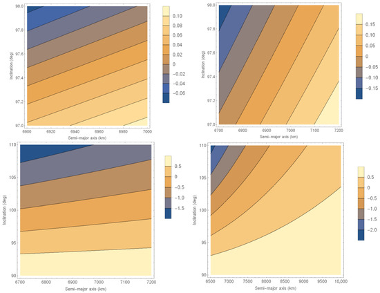
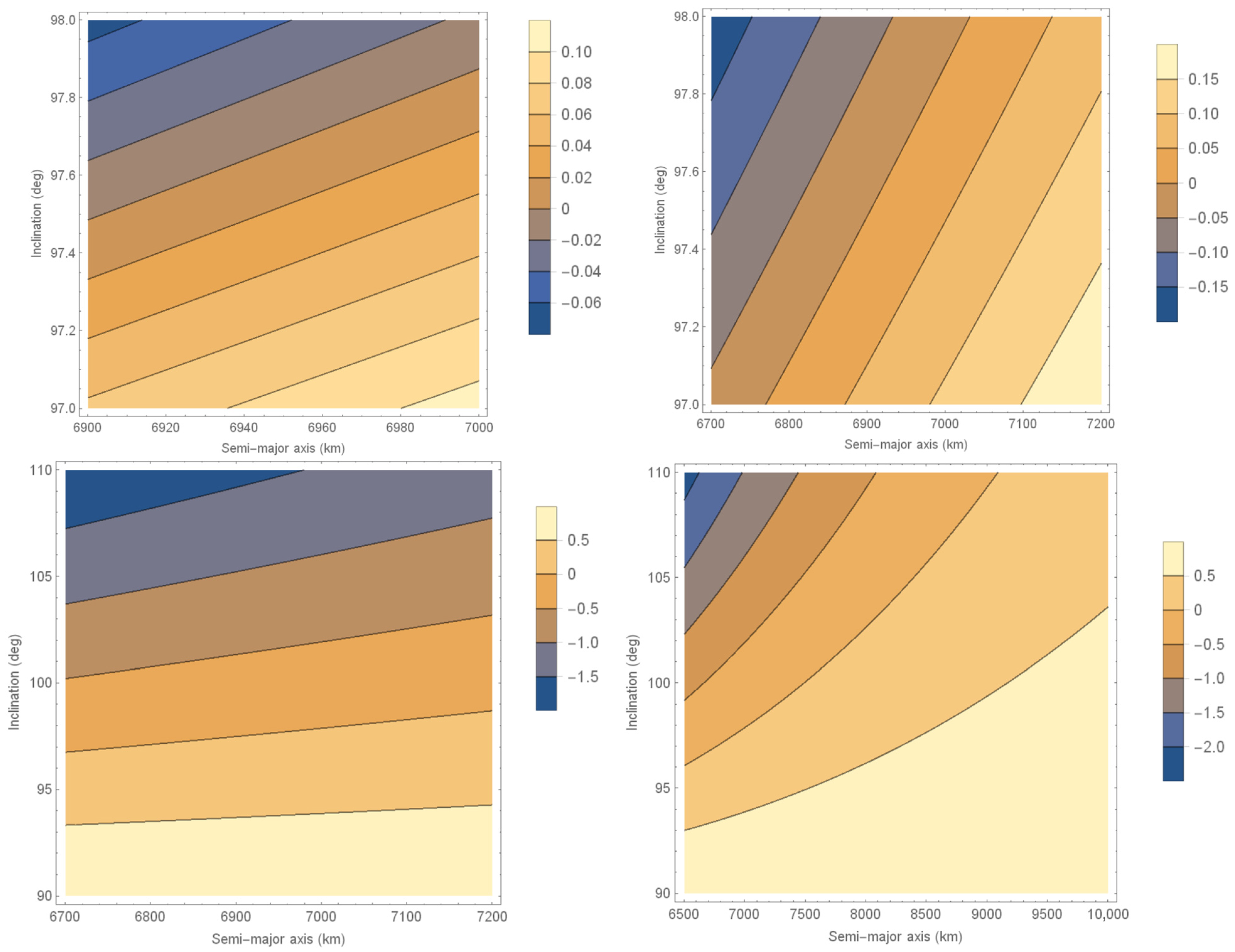
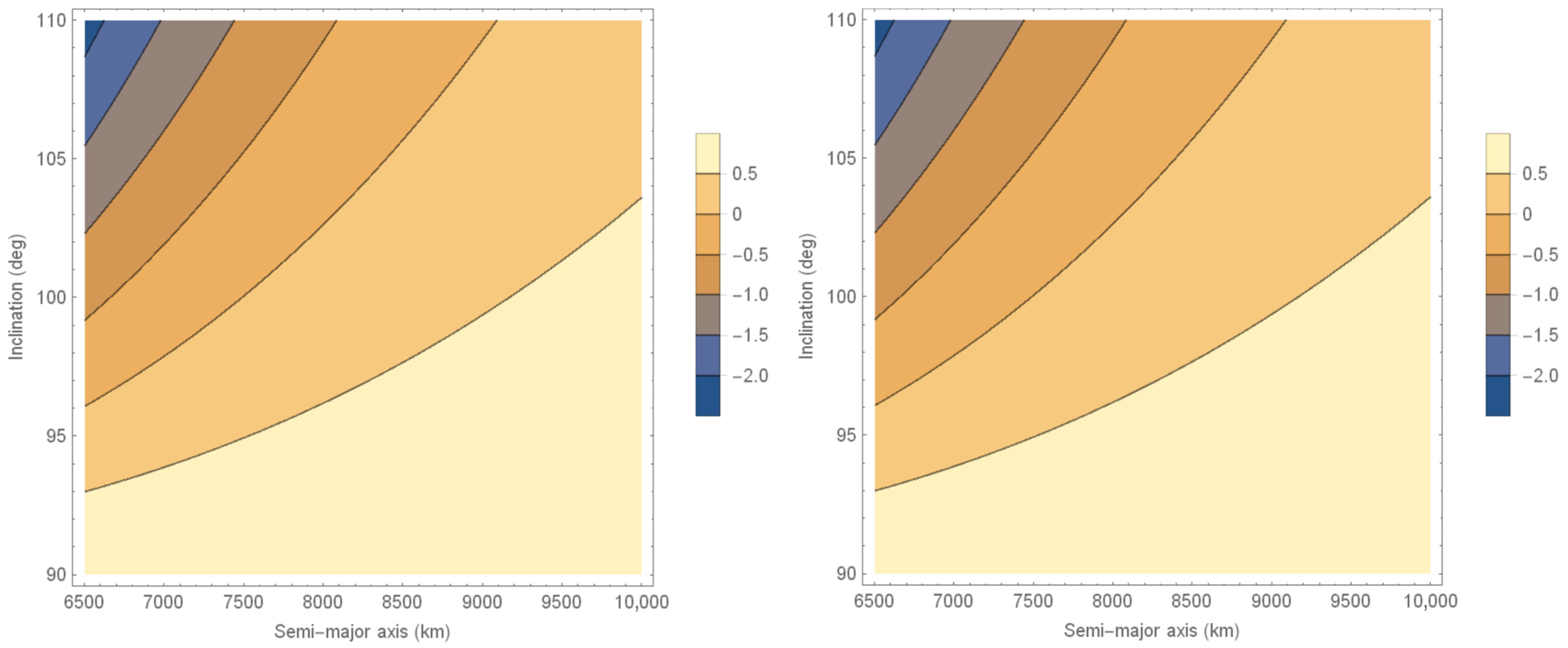
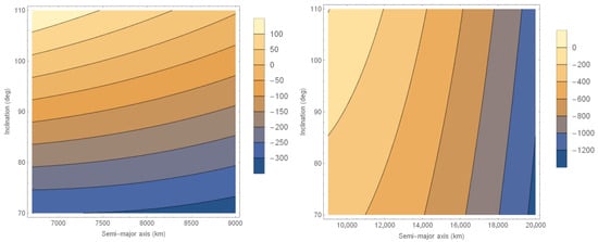
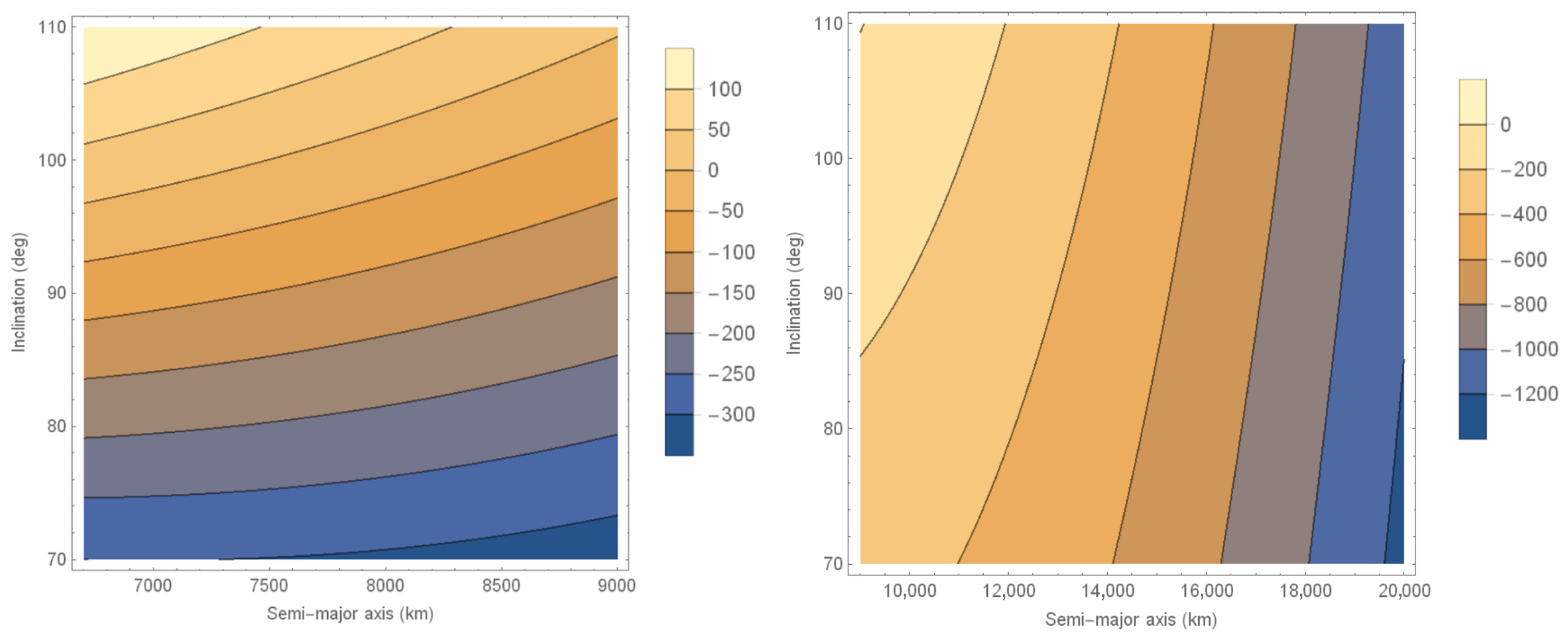
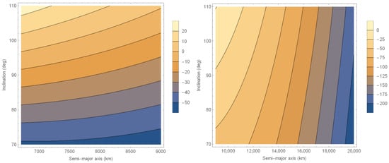
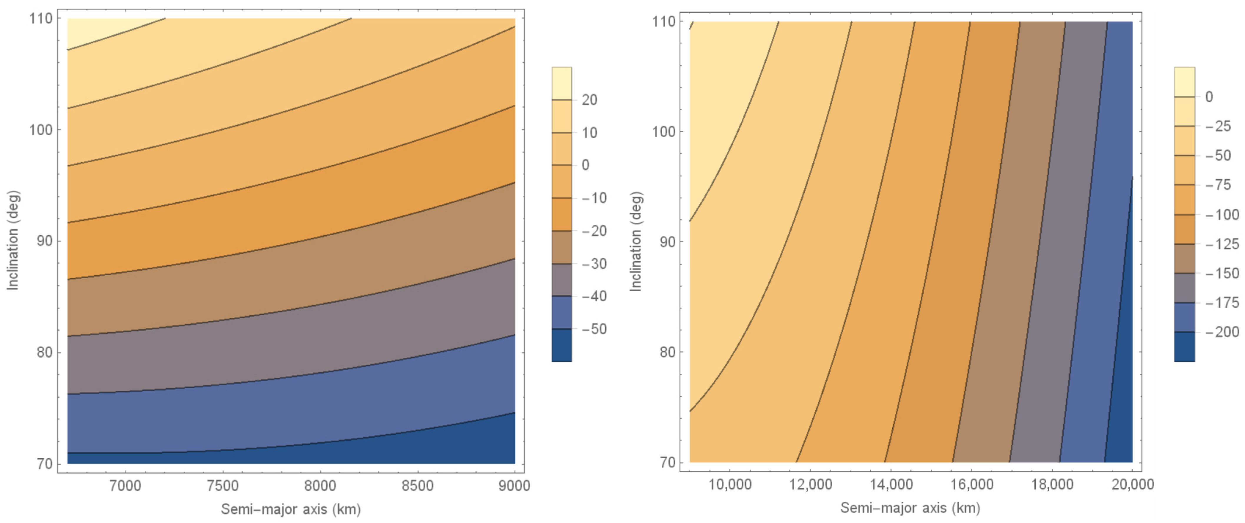
In Figure 1 we show the differences between 0.9863 degrees per day and the velocity given by Equation (12) converted to degrees per day for an eccentricity of 0.00035, which is a usual value for Sun-synchronous orbits, and different values for the inclination and semi-major axis. The line at 0 represents a natural Sun-synchronous orbit, and the regions around show the differences in the angular velocity that we need to compensate with propulsion, which is the electrodynamic tether in the present research, and if we need to have a sun-synchronous orbit with the semi-major axis given by the value shown on the horizontal axis (in km) and the inclination given by the vertical axis (in degrees). Different plots are made for different ranges of inclination and semi-major axis to better visualize the regions of interest.
Figure 1.
Differences between 0.9863 degrees per day and the velocity given by Equation (12) converted to degrees/day for an eccentricity of 0.00035.
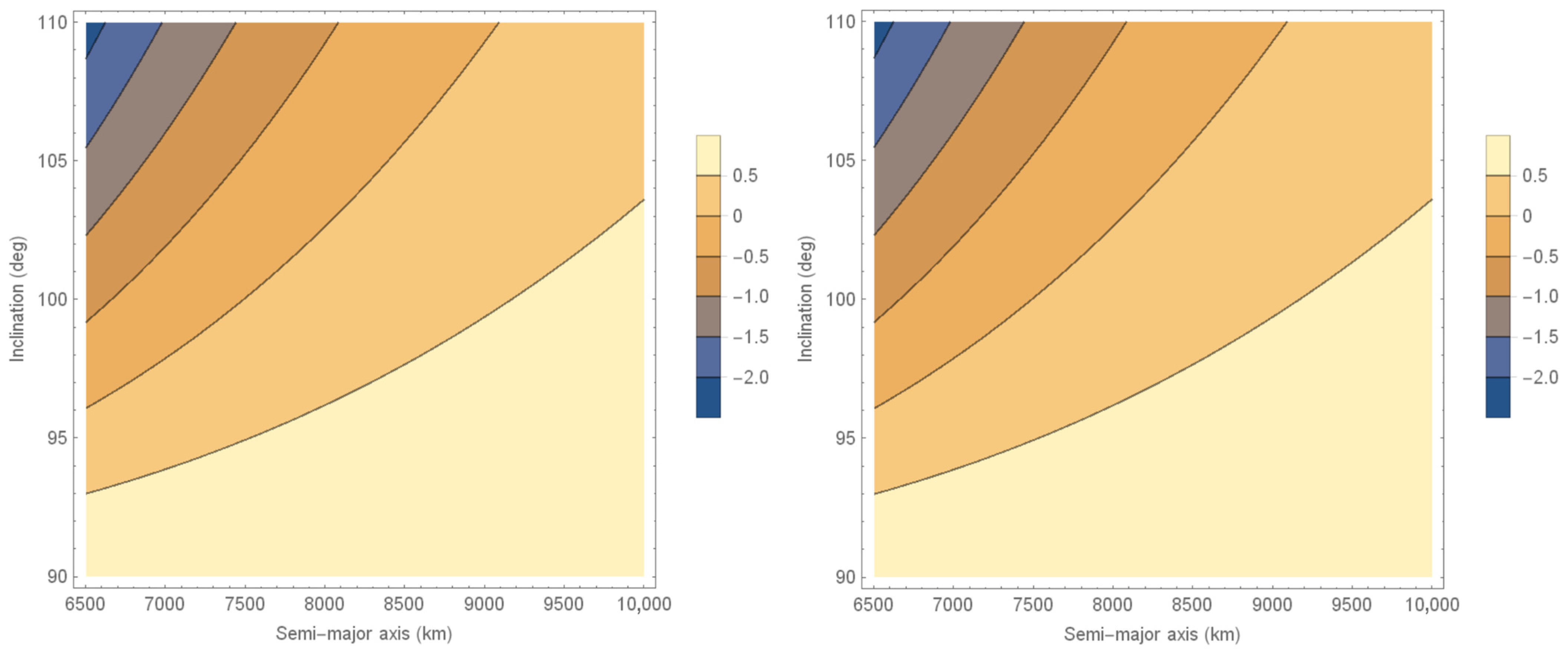
Figure 1 shows how small variations in inclination and/or semi-major axis can impact orbital mechanics, particularly in terms of the angular velocity of the variation of the longitude of the ascending node. Understanding these differences is crucial for selecting Sun-synchronous orbits. Figure 2 shows the same results for orbits, but with eccentricities 0.0007, 0.0014, 0.0056 and 0.0224. The goal is to cover a large range of values for the eccentricity. Larger values are not considered because they are far from circular and not recommended for remote sensing satellites. It is clear that the eccentricity has little effect on the results.
Figure 2.
Differences between 0.9863 degrees per day and the velocity given by Equation (12) converted to degrees/day for an eccentricity of 0.0007 (top, left), 0.0014 (top, right), 0.0056 (bottom, left) and 0.0224 (bottom, right).
Figure 1 and Figure 2 show that Sun-synchronous orbits are represented just by one line in each figure, and there is a constraint when choosing the Keplerian elements of those orbits. This is the main reason why using some type of propulsion can be useful. In particular, the results show the existence of artificial Sun-synchronous orbits on a much larger semi-major axis compared to the natural ones, which may be interesting for missions willing to cover larger areas of observation on the surface of the Earth.
Next, to be able to correct the differences in the angular velocities shown in Figure 1 and Figure 2, we have to introduce the force of the electrodynamic tether to correct the rate of the longitude of the ascending node. At this point it is important to look at Tragesser (2003) [27], because this paper gives the best current laws to correct every orbital element. Table 1 shows those current laws, but it is important to mention that, when using one of those current laws, all the orbital elements are affected, although in different magnitudes. Therefore, to make sure that we can use a control law for the current that does not affect the other orbital elements too much when correcting one of them, we build Table 2, which gives the variations of each orbital element after the application of each of the control laws proposed in Table 1 for one revolution for 1 A of current and 1 m of the tether. In this way, we can see the relative results to decide if it is possible to control one orbital element without affecting the other ones too much.
Table 1.
Current laws recommended for an electrodynamic tether to correct each Keplerian Element. I is a constant and ν the true anomaly of the satellite (Tragesser, 2003 [27]).
Table 2.
Variations of each Orbital Element per revolution of the satellite for each current law, assuming I = 1 and 1 m for the tether length.
To build Table 2 the integrations shown in Equations (7)–(11) were made using typical values for remote sensing satellites (Silva et al., 2023 [29]): a = 7000 km, e = 0.00035, i = 97.79°, ω = 93.84°, Ω = 186.09° and mass of the satellite of 2000 kg. The results are proportional to the mass of the satellite, so the relative results are the same for any size of satellite considered.
Some comments need to be made on the results shown in Table 2. First, inverting the sense of the flow of the current in the tether changes the signal of the variation, so negative values become positive and vice versa. Second, looking particularly at the variations in all orbital elements given by the current law I Sin(2(ω + ν)), the one that we will use to keep the time variation of the longitude of the ascending node at the desired value of 0.9863 deg/day, we see that its influences on the other orbital elements are smaller: eight orders of magnitude for the inclination; five orders of magnitude for the eccentricity; three orders of magnitude for the argument of perigee, which is not so important, since the orbits are near circular; four orders of magnitude for the semi-major axis.
Therefore, the next step is to obtain the product of I (the maximum value of the current), m (the mass of the satellite) and L (the size of the tether) that are required to complement the action of the flattening of the Earth to reach the value of 0.9863 deg/day for the time variation of the longitude of the ascending node.
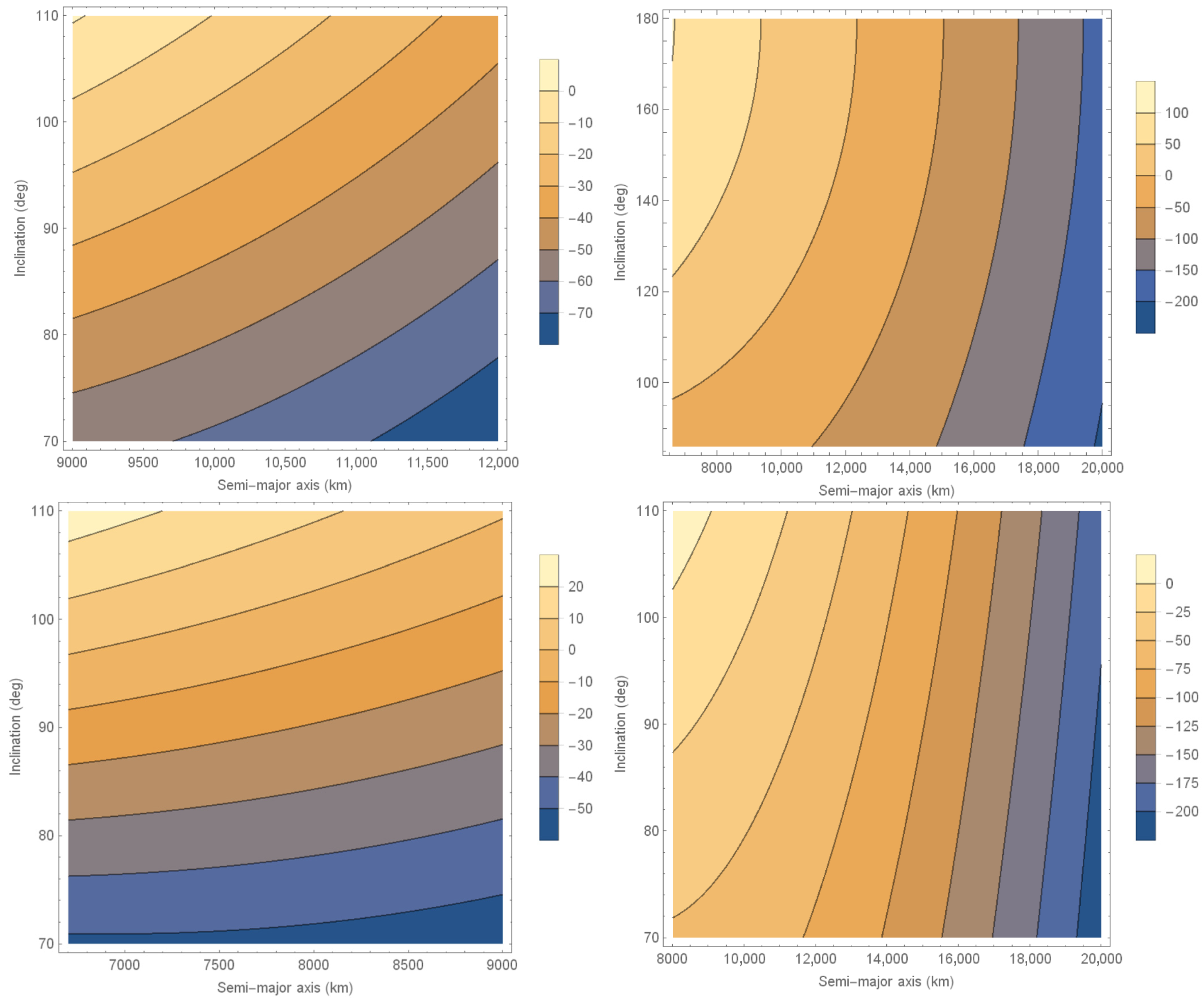
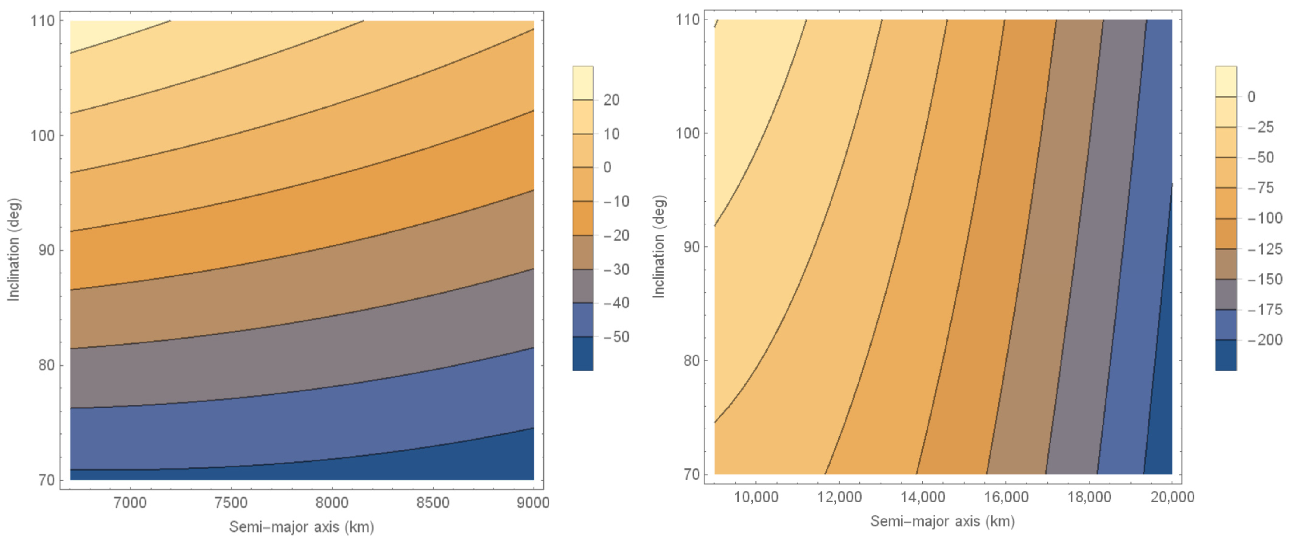
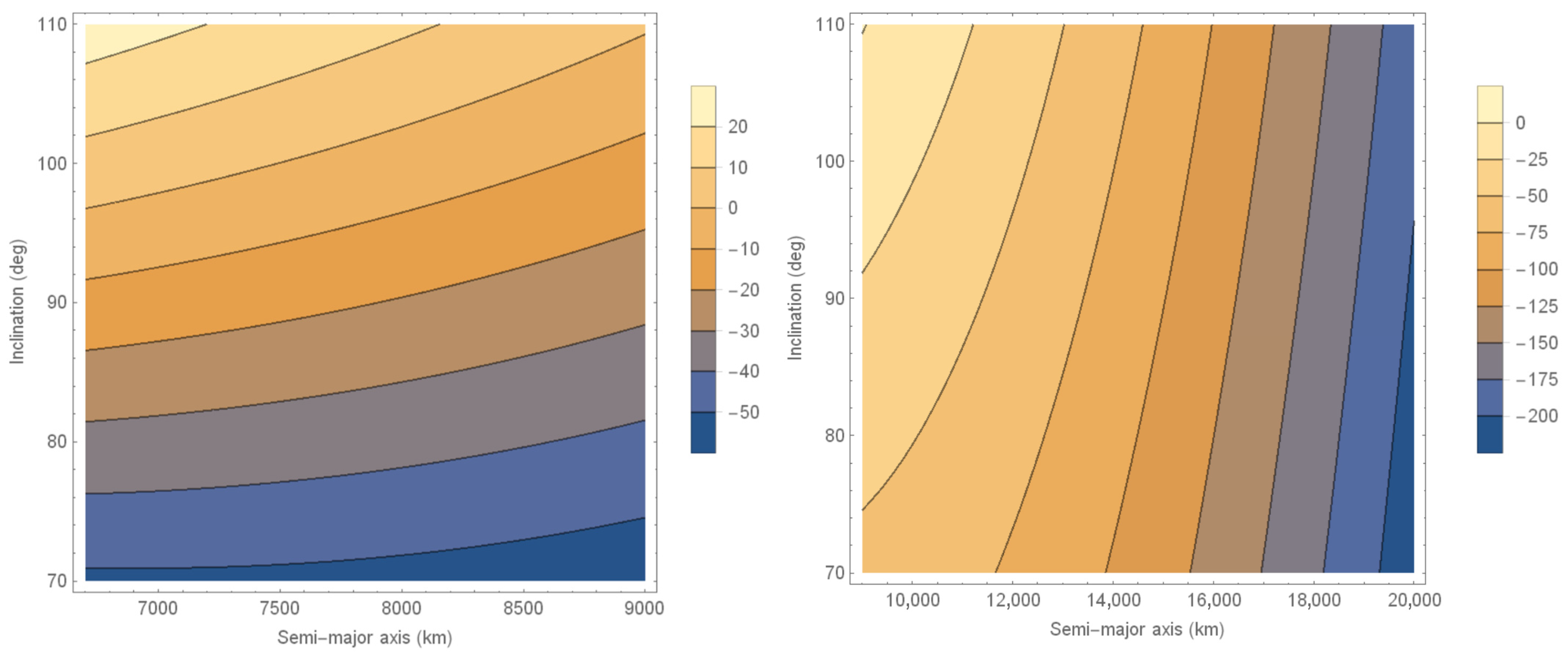
The variation of the longitude of the ascending node for one revolution due to the tether is given by Equation (11). So, if we multiply this variation by 24 h and divide the result by the orbital period of the spacecraft (that can be obtained from Kepler’s third law), we have the daily variation of the longitude of the ascending node coming from the electrodynamic tether. These results need to be equal to the difference between 0.9863 degrees per day and the angular velocity given by Equation (12) converted to degrees per day. Performing these steps, we get results like the ones shown in Figure 3, which has the semi-major axis (km) on the horizontal axis and the inclination (degrees) on the vertical axis. The color code shows the value of the product of I (Amperes), mass (kg) and the size of the tether L (km) for a given eccentricity of the orbit of the spacecraft and for different ranges of semi-major axis and inclination.
Figure 3.
Product of I (Amperes), mass (kg) and the size of the tether L (km) for an eccentricity of 0.00035 for different ranges of semi-major axis (km) and inclination (degrees).
An important point to consider here is the limits on the semi-major axis of natural Sun-synchronous orbits. Those limits depend on the inclination and eccentricity of the orbit, but Equation (12) can be used to calculate them. It is easy to see that the maximum semi-major axis is obtained for equatorial and circular orbits, because inclination of zero maximizes the cosine of the inclination, leaving space to increase the semi-lactus rectum; while eccentricity of zero makes it possible to increase the semi-major axis. Therefore, considering a circular and equatorial orbit, Equation (12) shows a maximum of 12,342.40 km for the semi-major axis for an artificial Sun-synchronous orbit, which means an altitude of about 5964.40 km. But equatorial orbits are not the best for observations of the Earth, because near-polar orbits can take advantage of the rotation of the Earth to observe the whole surface of the Earth. So, if we limit the inclination to between 70° and 110°, the maximum semi-major axis would be 9083.88 km, which means an altitude of 2705.88 km. Those numbers can be confirmed in the results shown here by looking at the lines for m.I.L = 0, which is the product of the mass of the satellite (m) by the maximum value of the current (I) and the size of the tether (L), which represent natural Sun-synchronous orbits.
The interval from 70 to 110 degrees for the inclination is used in the plots because it is very adequate for remote sensing satellites. The intervals of the semi-major axis emphasize values below and above 9000 km because this is about the limit that we can get from natural Sun-synchronous orbits.
The results shown here indicate that the proposed technique can increase the semi-major axis of the orbits using the tether to values around 20,000 km, as shown in the two plots in the right side of Figure 3, requiring values on the order of 150 kg.A.km for the tether, which means 150 kg multiplied by Amperes and kilometers. Even higher results can be obtained if we increase the product m.I.L.
The same is true for the limits on inclination, which can also be expanded by using the propulsion proposed here. From the line m.I.L = 0 in all the plots of Figure 3 we see that there are limits to the inclination. In the top-left plot this limit in the inclination to get natural Sun-synchronous orbits is about 110 degrees. This same plot shows that it is possible to get values like 70 degrees using an m.I.L on the order of 55 kg.A.km. Considering that the mission may have other constraints for the orbital elements, adding this flexibility can be important in some situations. The other plots of Figure 3 give more detail for different ranges of inclination and semi-major axis, giving more accurate values of the product m.I.L to get specific inclinations and semi-major axes.
As an example, we can see from the bottom right plot that an m.I.L product on the order of 5 kg.A.km (1/5 of the scale of colors from 0 to −25 kg.A.km) may increase the semi-major axis by about 500 km for a given inclination or reduce the inclination by about 4 degrees for a given semi-major axis. The design of the tether depends on the mass of the spacecraft. Assuming a 100 kg satellite, we would need a 500 A.km tether. It is important to note that those are large variations in terms of semi-major axis and inclination and can help to satisfy other constraints of the mission. Of course, smaller variations, which can be obtained with smaller requirements for the tether, are also important for some missions.
It is important to mention that the numbers obtained here for the product of the current by the mass of the satellite and the size of the tether are possible to obtain. Regarding the current, usual numbers in the literature are in the range 5–10 A. It is possible to perform several orbital maneuvers with this range of current, but Bechasnov (2021) [30] shows that it is possible to achieve currents up to 1000 A in a tether by using an autonomous generation of current with an onboard battery to avoid the limits given by the density of the external plasma. In this case, it is shown that a current of 1000 A demands 30 kW of power, which can be obtained by consuming 10 mg/s of hydrogen. The focus of this research is on the dynamics of the tether, but details of this idea can be seen in Bechasnov (2021) [30].
For an orbit mentioned before, assuming a 10 A current, we would need a 50 km tether. But, if we can use a battery providing 1000 A, a tether of only 0.5 km would be enough.
Even orbits very far from natural ones can be reached, although at a higher cost in the design of the tether. The maximum values in the ranges are about 200 kg.A.km, which would demand 20,000 A.km for a 100 kg satellite, requiring a 20 km tethers using a 1000 A battery; a large value, but not out of the scope of the already mentioned literature about tethers. But this would be the case only if increases in the semi-major axis on the order of more than 10.000 km were required, which is a very extreme situation.
Regarding inclination, we see that the natural orbits have a smaller range of options, from about 97° to 110°, so including only retrograde orbits. Artificial Sun-synchronous orbits can get values as low as 70°, at the cost of about 50 kg.A.km, which means a tether of 5 km considering a 100 kg satellite with a current of 1000 A. These are larger, but possible, values but required only for extremes and not usual changes in inclination.
Besides that, it is important to remember that a tether like this one can also be used for station keeping and/or de-orbiting the satellite, as shown later in this paper, so it would not be a device to be added to the spacecraft only to achieve artificial Sun-synchronous orbits. In fact, the main reason to include this device in the satellite may be to provide an option to de-orbit the satellite, as shown in the literature review of the present paper, which shows several studies working on this line. In that sense, to achieve artificial Sun-synchronous orbits could be one more application of this equipment, which would be already available in the satellite.
Figure 4 shows the product of I (Amperes) and the size of the tether L (km) for a satellite with a mass of 5.8 kg, which is the mass of the satellites of the DOVE constellation (Frazier and Hemingway, 2021 [31]). This is a very important constellation of Sun-synchronous small satellites, which are very good candidates to use the proposed technology, so some plots are made specifically for these satellites to get more accurate results. The small masses of those satellites reduce the requirements a lot in terms of current and/or tether length to achieve artificial Sun-synchronous orbits.
Figure 4.
Product of I (Amperes) and the size of the tether L (km) for an eccentricity of 0.00035 for different ranges of semi-major axis and inclination for a satellite with a mass of 5.8 kg.
Exploring the new values of inclination, Figure 4 shows that it is possible to change the inclination at a rate of about 11.25° per 150 A.km. Using a 10 A current it would be 11.25° per 15 km in tether size, reduced to only 0.15 km with the 1000 A battery.
Looking at the semi-major axis, it is possible to increase it at a rate of 8000 km per 800 A.km, meaning 8000 km per 80 km in tether size for the current of 10 A, or 0.8 km for a current of 1000 A. Inverting the calculations, this technique would give 100 km for the semi-major axis for each km in tether size. For a 1000 A battery, we would have an excellent value of 10,000 km for the semi-major axis for each km in tether size.
To compare with the regular low thrust (in m/s2) and variations of velocity required (in m/s), it is possible to look at Wu, Jiang and Li, 2015 [2]. The results show that the requirements depend on the orbit considered. Figure 7 of Wu, Jiang and Li, 2015 [2] shows that the acceleration required is in the range from 0.0122 to 0.002 m/s2 and the variations of velocity are in the interval from 70 to 30 m/s per revolution. Considering an orbit with a semi-major axis of 9000 km in Figure 7 mentioned above (from Jiang and Li, 2015 [2]), we would need about 38 m/s per revolution. An orbit like this one has an orbital period of 2.64 h, so, considering a mission of 10 years, it means about 33,000 revolutions, requiring about 1254 km/s of variation of velocity, a very large number. This is a strong point in favor of the tether, which does not use fuel.
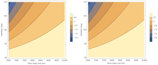
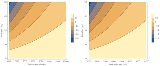
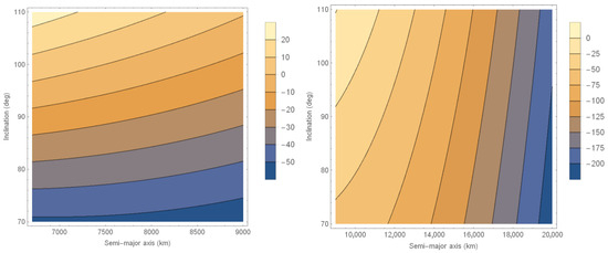
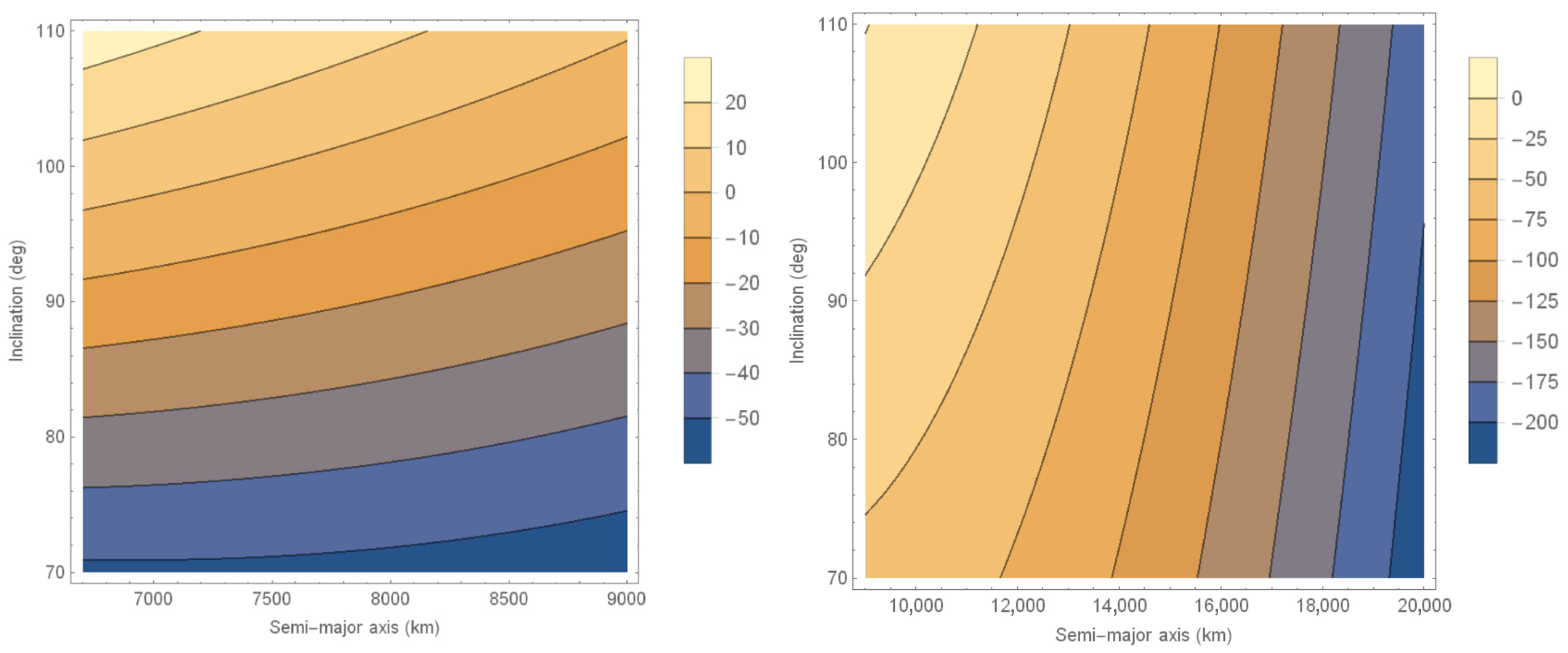
Figure 5, Figure 6, Figure 7 and Figure 8 show results similar to Figure 3, the product of I (Amperes), mass (kg) and the size of the tether L (km), for eccentricities 0.0007, 0.0014, 0.0056 and 0.0224, respectively. The same calculations made for an eccentricity of 0.00035 can be done for those eccentricities.
Figure 5.
Product of I (Amperes), mass (kg) and the size of the tether L (km) for an eccentricity of 0.0007.
Figure 6.
Product of I (Amperes), mass (kg) and the size of the tether L (km) for an eccentricity of 0.0014.
Figure 7.
Product of I (Amperes), mass (kg) and the size of the tether L (km) for an eccentricity of 0.0056.
Figure 8.
Product of I (Amperes), mass (kg) and the size of the tether L (km) for an eccentricity of 0.0224.
De-Orbiting the Satellite
The next step is to concentrate on the second main goal of the present paper, which is to show how to control the semi-major axis to reduce it faster and make the spacecraft de-orbit in shorter times, leaving space for a new spacecraft. The evolution of the other orbital elements in this phase of the mission is not important at this point, because the satellite will no longer be in use when it is de-orbiting. Besides that, Table 2 shows that, when focusing on changing the semi-major axis, we need to use the control law I = constant and, in this case, the variations in the semi-major axis are 11 orders of magnitude smaller when affecting the eccentricity and argument of perigee; 7 orders of magnitude smaller when affecting the inclination; and 15 orders of magnitude smaller when affecting the longitude of the ascending node. Those arguments show that we can focus on reducing the semi-major axis with no concerns about the other orbital elements. To proceed, we use Equation (7) to expand its integrand to get Equation (13).
Using a constant current I to control the semi-major axis, we can get Equation (14).
Considering that , we reach Equation (15).
This equation can be used to get the variation of the semi-major axis per revolution for a given orbit. A typical remote sensing satellite has a small eccentricity, so we can assume e = 0.00035 as an example. Equation (15) shows that the effects of different values are small, so the eccentricity does not affect the results much.
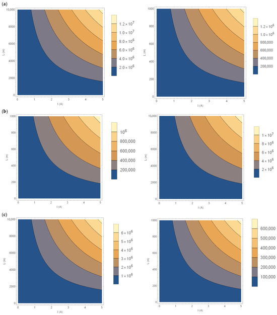
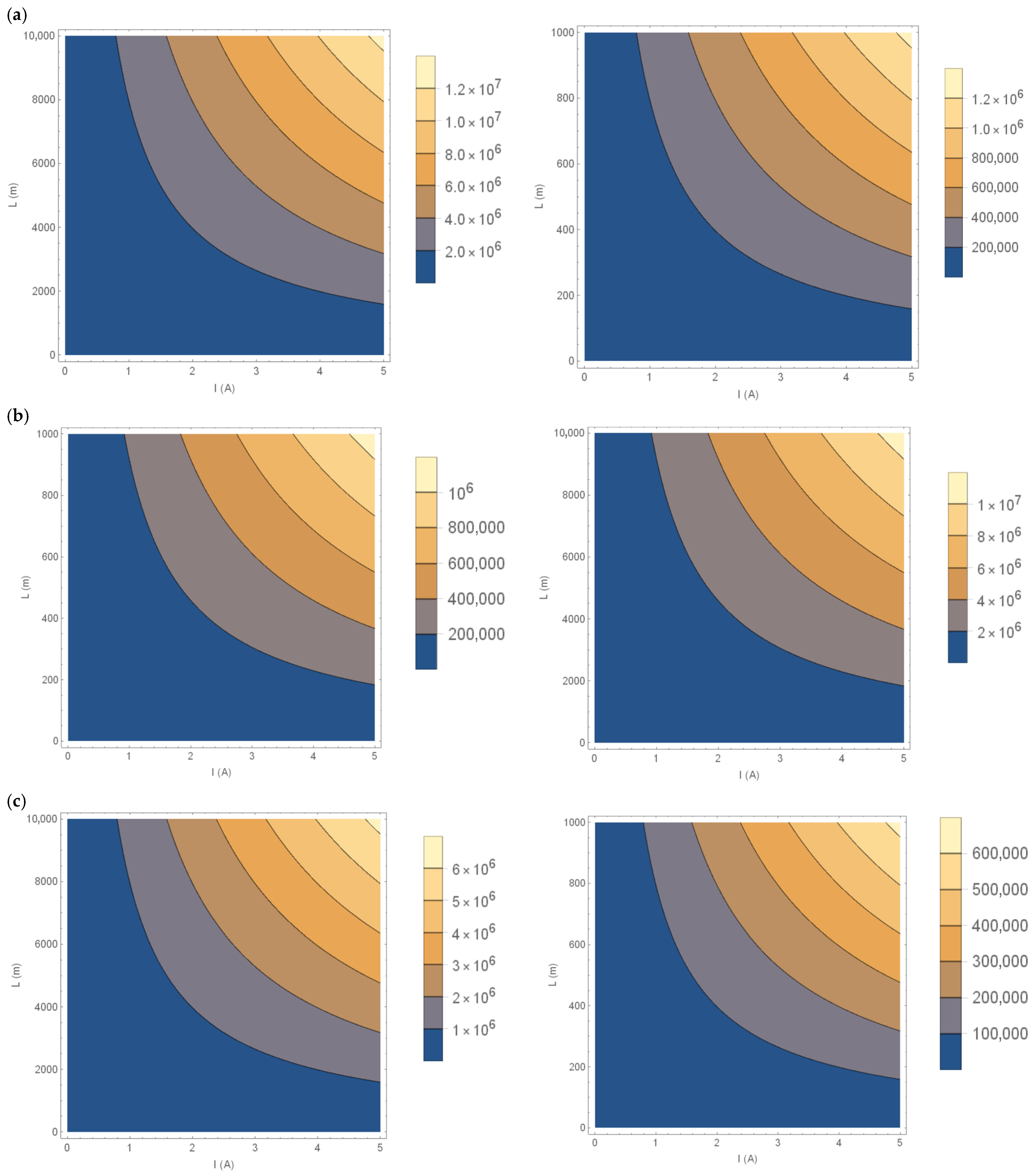
To make the results more generic, we can get the variation of the semi-major axis for one unit of mass (kg). The results obtained can be divided by the mass to get the variation of the semi-major axis for a given satellite. In other words, we will calculate . Figure 9 shows those results, using contour plots for the variation of ∆a.m as a function of tether length and current for different inclinations (0°, 30°, 60°) and assuming e = 0.00035. The plots demonstrate that a higher current and longer tether lengths result in greater changes in the semi-major axis, as expected, and the effect is more pronounced at lower inclinations.
Figure 9.
Current (Ampere) in the horizontal axis, length of the tether (meters) in the vertical axis and (meters.kg) in the contour plots for (a) i = 0, (b) i = 30 degrees, (c) i = 60 degrees. It is zero for i = 90 degrees.
An example of the use of this figure would be to verify the decrease in the semi-major axis for a satellite in an orbit with an inclination of 98 degrees, eccentricity 0.00035, current of 5 A and with a tether 2 km long. The result can be obtained from the top-right portion of Figure 9a multiplied by cos(98 deg) = 0.1392, to account for the inclination of 98 degrees, following Equation (15). From there we see that the product ∆a.m = (0.1392)(2.0 × 10⁶) = 2.78 × 10⁵ kg.m. Therefore, if the satellite is 2000 kg, the decrease will be 139 m per revolution. So, if the initial altitude is about 600 km and we need to reduce it to 150 km to reach the atmosphere of the Earth faster, 3237 revolutions around the Earth are necessary, which is about 270 days, if we consider the orbital period on the initial orbit, or 243 days, considering an average period of the orbits between 600 km and 150 km altitude, which is the point that we consider that the satellite will quickly re-enter the atmosphere of the Earth. Both are very short times for de-orbiting a satellite. Of course, those numbers can be reduced very much by increasing the tether size and/or the current that passes through the tether.
Different versions of this problem can be solved using figures like the one shown here. A different version of the problem is possible, where we can define a constraint for the de-orbiting time, and therefore the number of revolutions, and see options for the current and tether length required. Assuming the same satellite, suppose that we need to make the maneuver in 4800 revolutions around the Earth (about one year, considering the average period of the orbits during the decay). In this case, we need to reach ∆a.m = 1.85 × 10⁵ kg.m, which means, after making the same correction for the cosine of the inclination, about 1.33 × 10⁶ kg.m. We can use Figure 9a and get several possibilities. For example, keeping a current of 5A, we need a tether about 1.0 km long. If we use larger values for the current, the tether length can be much smaller. Of course, shorter decay times can be obtained in the same way.
At this point it is important to remember that there are international recommendations for removing a satellite 5 years after the end of its working life. It is possible to make this analysis taking into account those numbers. To reach this decay time rule, it would be necessary to de-orbit the satellite in about 24.000 revolutions. For this we need 2.66 × 10⁵ kg.m, which we can find in the top-right plot of Figure 9a. One possible solution would be a tether with 5 A and only 220 m in length. The calculations that will be shown in the section about station keeping will make clear that a natural decay of a satellite of this size would take several thousands of years. If we go back to old recommendations of removing the satellite 25 years after its end of life, those numbers would be really small for the current and/or tether size.
Next, Figure 10 shows a contour plot of ∆a.m as a function of tether length and inclination for a constant current of 5 A, a modest value that can be obtained even with no internal battery. This illustrates how the semi-major axis change is maximized at lower inclinations. There is one order of magnitude in the differences of for the same tether length when going from equatorial to near-polar orbits.
Figure 10.
Inclination (degrees) on the vertical axis, length of the tether (meters) on the horizontal axis and m.∆a (km.kg) in the contour plots for current of 5 A.
Figure 11 shows a contour plot of ∆a.m as a function of current and inclination for a constant tether length of 5 m. This further highlights the inverse relationship between inclination and the ability to change the semi-major axis using the electrodynamic tether. The same type of problem can be solved, this time using the inclination as variable.
Figure 11.
Inclination (degrees) on the vertical axis, current (Amperes) on the horizontal axis and m.∆a (meters.kg) in the contour plots for L = 5 m.
5. Station-Keeping Maneuvers
The goal of this part of the paper is to explain a bit about the effects of the perturbations involved in the dynamics of the satellite. The most important one is the atmospheric drag, which makes the satellite decay over time. Equation (10.19) from Chobotov, 1996 [28] can be used to make an estimate of the velocity of decay of a spacecraft due to drag. The equation is repeated here, as Equation (16), where µ = 3.986 × 10⁵ km3/s2 is the gravitational parameter of the Earth; ρ is the density of the atmosphere of the Earth, which can be found in Figure 10.12 from Chobotov, 1996 [28]; ; is the aerodynamic coefficient of the satellite, assumed to be 2.2, a usual number; A is the projected area of the satellite, assumed to be 10 m2.
Therefore, the results are very much dependent on the altitude and shape of the satellite, as well as the activity of the Sun, which interferes in the density of the atmosphere. So, to get accurate results, we need to consider specific missions. To be aligned with the focus of more general results of the present paper, we will assume average values for the parameters involved. So, for a satellite of 2000 kg and a semi-major axis of 7000 km (ρ = 10−15 kg/m3), Equation (16) gives a value of −5.8 × 10⁻¹⁰ km/s, or 3.13 × 10⁻⁶ km per orbital period of the satellite. This is a very small number and it indicates that natural decay would require more than 20,000 years.
Looking at Table 2, we see that a tether of 1 A and 1 m would change the semi-major axis by 1.7 × 10⁻⁵ km per revolution, which is more than the required 3.13 × 10⁻⁶ km. In this case, a tether of 1 A and only 0.1841 m would be enough for the station keeping on the semi-major axis. The same reference (Chobotov, 1996 [28]) indicates that for altitudes above 1000 km the effects of drag are negligible, even for long-term propagations.
The solar radiation pressure has very little effect on the problem of keeping artificial Sun-synchronous orbits. Masoud, Rahoma, Khattab and El-Salam, 2019 [4] carried out a detailed study including this perturbation and the results showed that the difference in the control required when considering solar radiation pressure or not is about 0.002%.
To consider effects of oscillations of the magnetic field, we need to remember that it is possible to alternate current laws to perform station keeping in all the orbital elements and avoid cumulative effects. The oscillation in B is quite unpredictable, so the solution would be to design the tether with some extra length and/or current to compensate for results that are smaller than the ones expected and then make orbit determinations frequently to see the real orbits and adjust the control laws to correct errors.
Thinking about long-term stability of the orbits, the idea is not to leave the orbital elements to grow in error but to correct them from time to time. As shown in Table 1 of the present paper, the tether has the flexibility to correct any orbital element with very little influence on the other elements. The calculations in this section show that the effort to control those errors is very small. So, every mission needs to define its tolerance to the variations of the orbital elements and, when this limit is reached, to change the current law to correct them. Performing this task from time to time will avoid large errors and corrections.
6. Conclusions
This paper explored the use of electrodynamic tethers as an innovative alternative for creating artificial Sun-synchronous orbits and performing the station keeping and de-orbiting of remote sensing satellites.
The results show the potential of electrodynamic tethers to provide a fuel-free propulsion method by utilizing interactions with the Earth’s magnetic field. This approach not only reduces operational costs but also extends the operational life of satellites.
The results shown here indicate that there is a limit, about 12,300 km on the semi-major axis, which can be reached for natural Sun-synchronous orbits. The proposed technique can increase the semi-major axis of the orbit using a tether up to 20,000 km or even longer. For the inclination, there is a limit near 97 degrees to achieve natural Sun-synchronous orbits and the proposed technique can reduce these values to around 70 degrees. This flexibility can be important for some missions, and it was shown that those results offer this flexibility while minimizing impacts on other orbital elements
Looking at the results we see that, regarding the inclination, it is possible to change the inclination at a rate of about 11.25° per 150 A.km for the Dove satellites, the most adequate ones to use this technology. It means that, using a 10 A current, it would be 11.25° per 15 km in tether size, reduced to only 0.15 km if using a 1000 A battery. For the semi-major axis, it is possible to increase it at a rate of 8000 km per 800 A.km, meaning 100 km per 1 km in tether size for a current of 10 A or 0.01 km for a current of 1000 A. Inverting the calculations, this technique would give 100 km in semi-major axis for each km in tether size. For a 1000 A battery, we would have an excellent value of 10,000 km in semi-major axis for each km in tether size.
Considering de-orbiting, the results showed that it is possible to de-orbit a 2000 kg satellite in 5 years using a tether with 5 A and of only 220 m in length, which is an excellent result.
To perform station keeping of a satellite of 2000 kg on a semi-major axis of 7000 km, it was shown that a tether with 1 A and of only 0.1841 m is enough, which is a very good result.
Since we derived equations, they can help in mission planning for satellites using electrodynamic tether propulsion systems, allowing for estimation of the time required for de-orbiting or orbital boosting maneuvers. Furthermore, employing tethers for de-orbiting satellites at the end of their operational life presents a promising solution to mitigate the growing problem of space debris, helping to maintain a cleaner orbital environment.
The results obtained here have the potential to benefit various fields, such as planetary and aerospace science and environmental monitoring, by providing a more efficient and sustainable control method for remote sensing satellites.
As a summary, the use of electrodynamic tethers is a growing area of research, with the potential to change how satellites are managed and operated in space. These conclusions show the significance and feasibility of using electrodynamic tethers in space engineering, opening new possibilities for the future of satellite technology.
Author Contributions
Conceptualization, A.F.B.A.P. and V.R.; Methodology, A.F.B.A.P. and V.R.; Software, A.F.B.A.P.; Investigation, A.F.B.A.P. and V.R.; First version of the text, A.F.B.A.P. and V.R.; Final version of the text, A.F.B.A.P. and V.R. All authors have read and agreed to the published version of the manuscript.
Funding
This paper has been supported by the Ministry of Science and Higher Education of the Russian Federation under Agreement No. FSSF-2024-0005.
Data Availability Statement
The original contributions presented in the study are included in the article, further inquiries can be directed to the corresponding author.
Conflicts of Interest
The authors declare no conflicts of interest.
References
- Li, Z.L.; Wu, H.; Duan, S.B.; Zhao, W.; Ren, H.; Liu, X.; Zhou, C. Satellite remote sensing of global land surface temperature: Definition, methods, products, and applications. Rev. Geophys. 2023, 61, e2022RG000777. [Google Scholar] [CrossRef] [Scilit]
- Wu, Z.; Jiang, F.; Li, J. Extension of frozen orbits and Sun-synchronous orbits around terrestrial planets using continuous low-thrust propulsion. Astrophys. Space Sci. 2015, 360, 12. [Google Scholar] [CrossRef] [Scilit]
- Macdonald, M.; McKay, R.; Vasile, M.; Frescheville, F.B. Extension of the sun-synchronous orbit. J. Guid. Control. Dyn. 2010, 33, 1935–1940. [Google Scholar] [CrossRef] [Scilit]
- Masoud, A.; Rahoma, W.A.; Khattab, E.H.; El-Salam, F.A. Design of Artificial Sun-Synchronous Orbits with Main Zonal Harmonics and Solar Radiation Pressure Using Continuous Low-Thrust Control Strategies. Open Astron. 2019, 28, 124–130. [Google Scholar] [CrossRef] [Scilit]
- Xie, K.; Yuan, H.; Liang, F.; Wang, W.; Xia, Q. Lorentz force characteristics of a bare electrodynamic tether system with a hollow cathode. J. Astronaut. Sci. 2021, 68, 327–348. [Google Scholar] [CrossRef] [Scilit]
- Hoyt, R.; Forward, R. Performance of the terminator tether for autonomous deorbit of LEO spacecraft. J. Astron. Sci. 1989, 37, 433–450. [Google Scholar]
- Yamagiwa, Y. Performance Analysis of Electrodynamic Tether Orbit Transfer System for Round Trip Mission. J. Space Technol. Sci. 1997, 13, 17–25. [Google Scholar]
- Johnson, L.; Herrmann, M. International Space Station Electrodynamic Tether Reboost Study; NASA TM-1998-208538; NASA: Washington, DC, USA, 1998.
- Santangelo, A.; Johnson, L.; Gilchrist, B.; Hoffman, J.; Lorenzini, E.; Estes, R. Advancing electrodynamic tethers to commercially viable systems-step-airseds. In Proceedings of the NASA/JPL/MSFC/AIAA 10th Annual Advanced Space Propulsion Workshop, Huntsville, AL, USA, 5–8 April 1999; Volume 2, pp. 602–622. [Google Scholar]
- Gilchrist, B.E.; Johnson, L.; Bilen, S.G. Space electrodynamic tether propulsion technology: System considerations and future plans. In AIAA Paper 99-2841; American Institute of Aeronautics and Astronautics (AIAA): Reston, VA, USA, 1999. [Google Scholar]
- Lanoix, E.L.M.; Misra, A.K.; Modi, V.J.; Tyc, G. Effect of Electromagnetic Forces on the Orbital Dynamics of Tethered Satellites. In AAS/AIAA Spaceflight Mechanics Meeting; Kluever, C.A., Ed.; Univelt, Inc.: San Diego, CA, USA, 1999. [Google Scholar]
- Vas, I.E.; Kelly, T.J.; Scarl, E.A. Space Station Reboost with Electrodynamic Tethers. J. Spacecr. Rocket. 2000, 37, 154–164. [Google Scholar] [CrossRef] [Scilit]
- PelKaez, J.; Lopez-Rebollal, L.M.; Ahedo, E. Dynamic stability of a bare tether as a deorbiting device. In AAS Paper 02-200; American Astronautical Society: Springfield, VA, USA, 2002. [Google Scholar]
- PelKaez, J.; Lopez-Rebollal, L.M.; Lorenzini, E.C. Damping in rigid electrodynamic tethers on inclined orbits. In AAS Paper 01-190; American Astronautical Society: Springfield, VA, USA, 2001. [Google Scholar]
- Valmorbida, A.; Olivieri, L.; Brunello, A.; Sarego, G.; Sánchez-Arriaga, G.; Lorenzini, E.C. Validation of enabling technologies for deorbiting devices based on electrodynamic tethers. Acta Astronaut. 2022, 198, 707–719. [Google Scholar] [CrossRef] [Scilit]
- Li, X.; Yang, K.; Li, L.; Yao, F. Dynamic modeling and analysis of electrodynamic multi-tether system. Space Sci. Technol. 2023, 3, 0057. [Google Scholar] [CrossRef] [Scilit]
- Sánchez-Arriaga, G.; Lorenzini, E.C.; Bilén, S.G. A review of electrodynamic tether missions: Historical trend, dimensionless parameters, and opportunities opening space markets. Acta Astronaut. 2024, 225, 158–168. [Google Scholar] [CrossRef] [Scilit]
- Slavinskis, A.; Janhunen, P. Advances in CubeSat Sails and Tethers. Aerospace 2024, 11, 1016. [Google Scholar] [CrossRef] [Scilit]
- Salazar, F.J.T.; De Almeida Prado, A.F.B.; De Moraes, R.V. Lunar capture orbits using a non-planar tether cutting maneuver. J. Braz. Soc. Mech. Sci. Eng. 2025, 47, 236. [Google Scholar] [CrossRef] [Scilit]
- Prado, A.F.B.A.; Razoumny, Y.; Gomes, V.M.; Santos, L.B.T. Designing space tethers to perform orbital maneuvers to remove space debris. Eur. Phys. J.-Spec. Top. 2025, 234, 7917–7924. [Google Scholar] [CrossRef] [Scilit]
- Salazar, F.J.T.; Prado, A.F.B.A. Suppression of Chaotic Motion of Tethered Satellite Systems Using Tether Length Control. J. Guid. Control. Dyn. 2021, 45, 580–586. [Google Scholar] [CrossRef] [Scilit]
- Seppänen, H.; Rauhala, T.; Kiprich, S.; Ukkonen, J.; Simonsson, M.; Kurppa, R.; Janhunen, P.; Hæggström, E. One kilometer (1 km) electric solar wind sail tether produced automatically. Rev. Sci. Instrum. 2013, 84, 095102. [Google Scholar] [CrossRef] [Scilit]
- Janhunen, P. Electrostatic plasma brake for deorbiting a satellite. J. Propuls. Power 2010, 26, 370–372. [Google Scholar] [CrossRef] [Scilit]
- Mengali, G.; Quarta, A.A.; Janhunen, P. Electric sail performance analysis. J. Spacecr. Rocket. 2008, 45, 122–129. [Google Scholar] [CrossRef] [Scilit]
- Chen, Y.; Huang, R.; Ren, X.; He, L.; He, Y. History of the tether concept and tether missions: A review. Int. Sch. Res. Not. 2013, 1, 502973. [Google Scholar] [CrossRef] [Scilit]
- Chen, Y.; Huang, R.; He, L.; Ren, X.; Zheng, B. Dynamical modelling and control of space tethers: A review of space tether research. Nonlinear Dyn. 2014, 77, 1077–1099. [Google Scholar] [CrossRef] [Scilit]
- Tragesser, S.G.; San, H. Orbital Maneuvering with Electrodynamic Tethers. J. Guid. Control. Dyn. 2003, 26, 805–810. [Google Scholar] [CrossRef] [Scilit]
- Chobotov, V.A. (Ed.) Orbital Mechanics, 2nd ed.; AIAA: Reston, VA, USA, 1996. [Google Scholar]
- Silva, W.R.; Garcia, R.V.; Pardal, P.C.P.M.; Kuga, H.K.; Zanardi, M.C.F.P.S.; Baroni, L. The extended H∞ particle filter for attitude estimation applied to remote sensing satellite CBERS-4. Remote Sens. 2023, 15, 4052. [Google Scholar] [CrossRef] [Scilit]
- Bechasnov, P.M. Assessment of the properties of electrodynamic tethers with autonomous charge generation. AIP Conf. Proc. 2021, 2318, 040003. [Google Scholar] [CrossRef] [Scilit]
- Frazier, A.E.; Hemingway, B.L. A Technical Review of Planet Smallsat Data: Practical Considerations for Processing and Using Planet Scope Imagery. Remote Sens. 2021, 13, 3930. [Google Scholar] [CrossRef] [Scilit]

Disclaimer/Publisher’s Note: The statements, opinions and data contained in all publications are solely those of the individual author(s) and contributor(s) and not of MDPI and/or the editor(s). MDPI and/or the editor(s) disclaim responsibility for any injury to people or property resulting from any ideas, methods, instructions or products referred to in the content. |
© 2026 by the authors. Licensee MDPI, Basel, Switzerland. This article is an open access article distributed under the terms and conditions of the Creative Commons Attribution (CC BY) license.