


Abstract
With the widespread deployment of SRAM-based FPGAs across multiple application scenarios, the soft error resilience of FPGAs has become critically important. To mitigate errors, current mainstream techniques either incur significant PPA (Performance, Power, Area) overhead or exhibit inadequate fault tolerance. Addressing this fault-tolerance–PPA trade-off, this study reduces resource consumption in Triple Modular Redundancy (TMR) implementations while deploying high-efficiency hardening methods at alternative granularity tiers. We propose a multi-tier spatiotemporal hardening framework and evaluation method (MSHE-SE), achieving two key contributions on a 70-million-gate FPGA platform: full-flow, full-granularity protection from RTL to post-physical-implementation netlists by integrating spatiotemporal methods across multiple FPGA EDA stages; and dual-mode fault injection validation utilizing synergistic JTAG and SEM mechanisms. A pseudo-random sequence generator emulates real-world environments to evaluate the system Mean Time Between Failures (MTBF) of FPGA designs. Finally, experimental results demonstrate that, compared to commercial TMR tools, the proposed method reduces LUT resource utilization by 10.9–45.7% and enhances system MTBF by an average factor of 18.28×.
1. Introduction
Field Programmable Gate Arrays (FPGAs) have become indispensable in a broad spectrum of applications—ranging from aerospace and nuclear research to data centers and AI accelerators—thanks to their flexibility, customizability, and support for high concurrency. However, as process geometries shrink and logic density increases, FPGAs become increasingly vulnerable to soft errors, particularly Single Event Upsets (SEUs) induced by radiation or charged particles. These transient faults may corrupt the configuration RAM (CRAM) or user data paths, potentially leading to catastrophic system failures.
Among the many application domains of FPGAs, space and military missions are typically long-duration and operate in harsh environments. High-energy nuclear applications expose FPGAs directly to intense particle radiation, demanding exceptional single-device radiation resilience. Furthermore, electronics deployed in high-altitude or airborne systems experience radiation levels tens to hundreds of times higher than those at sea level [1,2]. Even large-scale terrestrial applications—such as data centers, cloud computing platforms, and telecom infrastructure—while not exposed to extreme conditions, involve massive FPGA node counts. For system-wide stability, these domains also place stringent requirements on radiation tolerance at the FPGA level.
Traditionally, fault-tolerant design approaches such as TMR and scrubbing have been employed to mitigate soft errors. While effective, these methods often result in substantial Performance, Power, and Area (PPA) overheads, limiting their applicability in resource- or energy-constrained environments. Furthermore, existing solutions tend to address soft error resilience at isolated stages of the FPGA toolchain, lacking a unified and systematic hardening architecture. Recent comprehensive surveys have further analyzed reliability challenges and protection strategies in FPGA-based reconfigurable systems [3,4].
To address these challenges, we propose MSHE-SE: a multi-tier spatiotemporal hardening and evaluation framework for soft errors. This framework provides a full-flow, full-granularity spatiotemporal resistance solution by integrating hardening techniques across different stages of FPGA development—from register transfer level (RTL) through to post-routing physical netlists. Our key contributions include the following:
- We proposed a spatiotemporal hardening framework and evaluation method, MSHE-SE, powered by a real-time Soft-Error Mitigation (RT-SEM), a Hierarchical and Synchronized TMR (HS-TMR), and an Adaptive In-Place Soft-Error Mitigation (AIP-SEM). The above techniques, together with the conventional FPGA EDA flow, provide a full-process soft error resilience enhancement for FPGA design.
- We proposed a JTAG/Serial dual-mode fault injection method that integrates JTAG and ICAP-based methods. This provides an evaluation approach for real-world system-level MTBF.
- We evaluate the soft error resilience boost of the MSHE-SE framework against Mentor’s Precision Hi-Rel using the dual-mode fault injection method. Experimental results show that our framework achieves an average of 18.28× improvement in MTBF, while reducing LUT resource consumption by up to 45.7% compared to commercial TMR tools.
The remainder of this paper is organized as follows. Section 2 introduces the underlying mechanisms of soft errors and surveys related soft error mitigation techniques. Section 3 outlines the proposed multi-tier hardening framework and its integration within the FPGA design flow. Section 4 presents the runtime hardening strategy based on a real-time soft error mitigation engine (RT-SEM). Section 5 and Section 6 discuss static hardening strategies implemented at the post-synthesis and post-routing stages, respectively. Section 7 describes our dual-mode fault injection and MTBF evaluation methodology. Section 8 provides experimental results demonstrating the effectiveness of our framework, and finally, Section 9 concludes the paper.
2. Background and Related Works
2.1. Soft Errors in FPGAs
Soft errors, also known as transient faults, do not cause permanent damage to silicon but can alter logic or data temporarily. In SRAM-based FPGAs, SEUs primarily affect CRAM, leading to persistent changes in logic behavior until reconfiguration occurs. Unlike ASICs, the reprogrammable and distributed memory architecture of FPGAs makes them more susceptible to these faults.
Soft errors in FPGAs typically fall into the following categories:
- Single Event Upset (SEU): Bit flips in configuration memory, affecting LUT logic, routing, or state elements.
- Multiple Bit Upset (MBU): Correlated bit flips caused by high-energy particles, more common in advanced nodes.
- Common Mode Failures (CMFs): Errors affecting multiple redundant branches simultaneously due to shared routing or physical proximity.
Given the increased vulnerability and deployment of FPGAs in critical systems, there is a growing demand for comprehensive and balanced soft error mitigation techniques.
2.2. Existing Hardening Techniques
Radiation hardening techniques can be broadly categorized into hardware-level and software-level approaches. Hardware hardening includes the use of radiation-hardened materials, manufacturing processes, and special layout structures, which are generally controlled by the chip vendor and fabrication technology. In contrast, software-level techniques offer greater flexibility and accessibility for end users. These include TMR, scrubbing mechanisms, and in-place fault-tolerant algorithms.
TMR replicates logic modules into three copies and uses a majority voter to mask transient faults [5]. It is the most widely adopted software-level mitigation strategy, but suffers from significant PPA overhead and is sensitive to CMFs, such as shared routing upsets. Furthermore, it cannot correct accumulated errors over time [6].
Scrubbing techniques address accumulated SEUs by periodically reloading the configuration memory [4,7], often in combination with TMR, yet still leave a vulnerability window during scrubbing intervals [1]. Scrubbing techniques also introduce extra circuit area and complexity, requiring careful trade-off between overhead and effectiveness.
In-place fault-tolerant algorithms target unused or don’t-care configuration bits within LUTs. By optimizing these idle bits using error-resistance-oriented resynthesis, they help mitigate errors caused by SEUs in upstream logic cones. This technique introduces negligible PPA overhead but increases EDA tool runtime and still cannot address accumulated soft errors.
These three categories of software mitigation techniques are independent. They can work together to further enhance the soft error resilience of FPGA designs.
3. Multi-Tier Hardening Technique
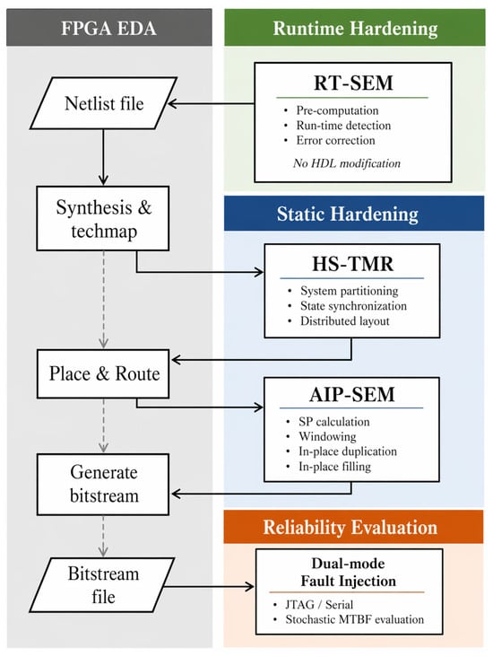
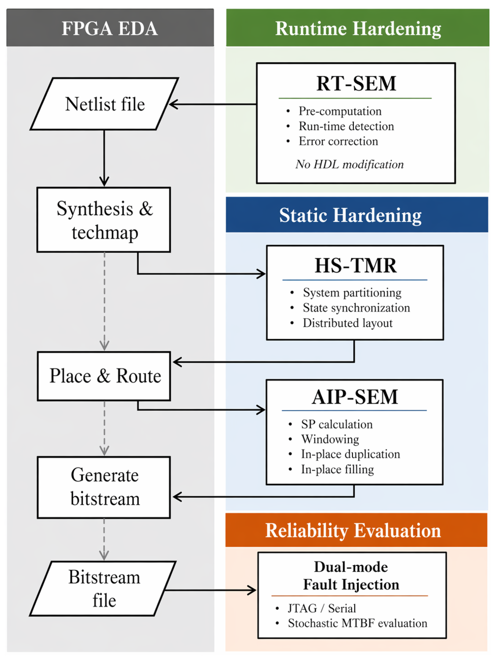
Figure 1 demonstrates the proposed multi-tier spatiotemporal hardening framework. Processes in grey represent the conventional FPGA EDA design flow. To provide sufficient soft error resilience to FPGAs, this study introduces multiple hardening strategies at different FPGA EDA stages. These strategies are categorized into runtime hardening and static hardening. Runtime hardening is implemented during the design phase. By the incorporation of an additional RT-SEM core, it is able to detect and correct soft errors during the FPGA designs’ runtime.
Figure 1.
The multi-tier hardening technique and its position in the traditional FPGA EDA flow.
Static hardening comprises two steps: TMR hardening and AIP-SEM hardening. The former, executed at the post-synthesis-and-techmap phase, provides basic soft error resilience, but also incurs significant Performance, Area, and Power (PPA) overhead. This study employs key techniques, including system hierarchy and state synchronization to reduce the logic resource consumption of TMR. Subsequently, a heuristic in-place fault tolerance algorithm is introduced at the post-place-and-route phase to further enhance FPGA reliability without additional PPA overhead.
Additionally, we propose a dual-mode JTAG/Serial fault injection methodology capable of evaluating real-time hardening techniques utilizing ICAP, which powers the RT-SEM technique.
4. Runtime Hardening at Design Phase
During the design phase, FPGA designs are typically represented in HDLs. At this higher abstraction level, soft error mitigation is usually implemented by introducing additional resources, which include TMR and supplementary scrubbing circuits. In this study, we proposed a real-time soft error mitigation (RT-SEM) technique, which uses a decoupled architecture, requiring no modification to user’s HDL code. The RT-SEM could achieve millisecond-level repair latency while specifically protecting CRAM, with only 15% to 20% additional resource overhead.
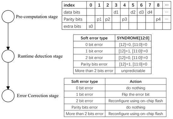
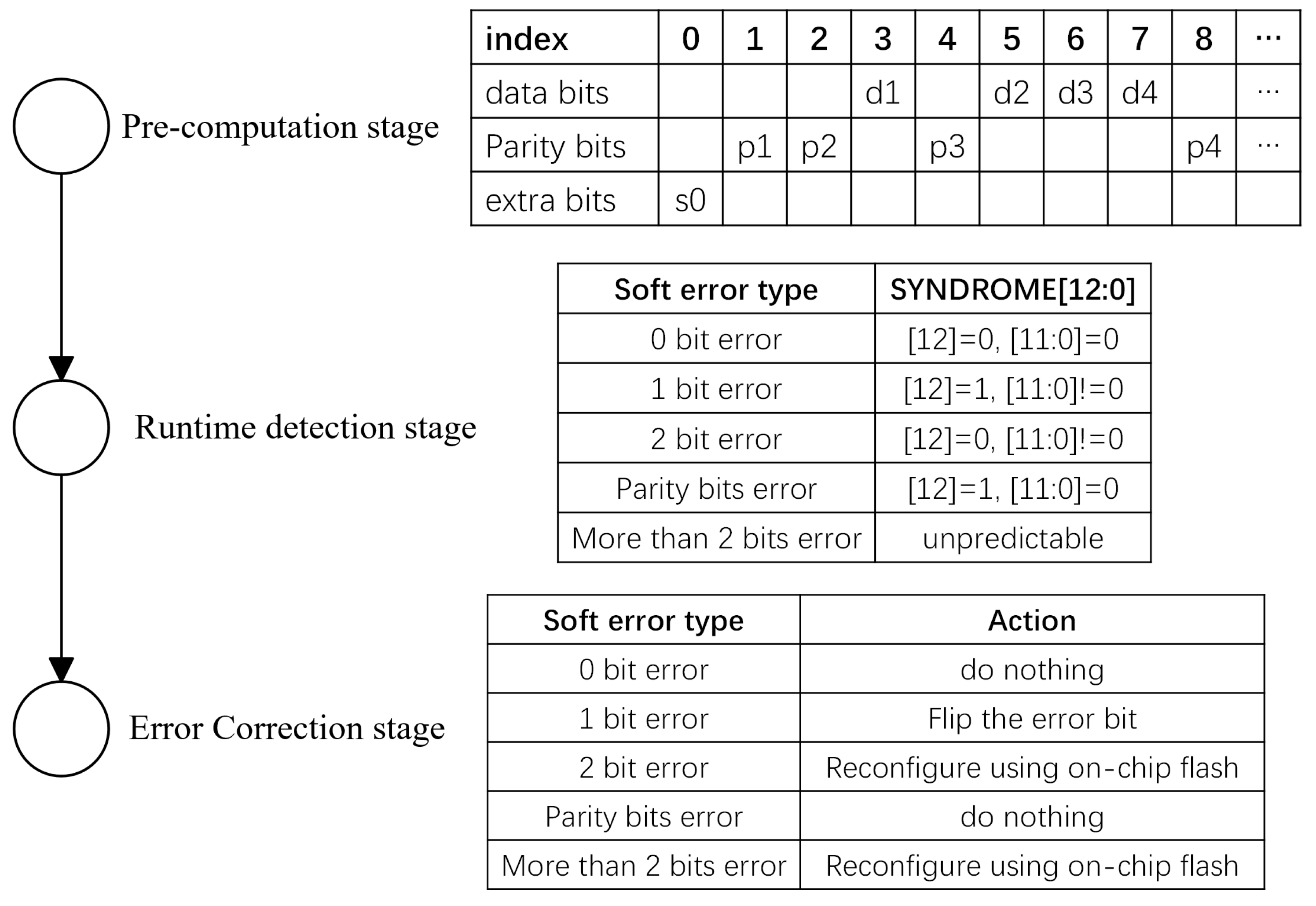
The RT-SEM is powered by Hamming code and has three stages, as shown in Figure 2, including the pre-computation stage, the runtime detection stage, and the error correction stage [8]. Compared to traditional single-grained scrubbing, recent brain-inspired hybrid-grained approaches [9] have demonstrated significant improvements in recovery efficiency.
Figure 2.
Three stages of the RT-SEM technique.
4.1. Pre-Computation Stage
The first stage is to preset the Hamming codes, which can detect and correct single-bit errors while also identifying double-bit errors in data by strategically adding parity bits. This stage pre-computes the parity bits for each configuration frame before the design starts. Additionally, To avoid missing soft errors during runtime, the pre-computation stage should start as soon as possible, which means right after the bitstream download is finished.
After computation, the parity bits of each configuration frame are stored in the BRAM as shown in Figure 2, where parity bits are placed at the index of 2i, like {1, 2, 4…}, data bits are placed at the rest index, like {3, 5, 6…}, and an extra parity bit is placed at index 0.
Given a data word of length k bits, we determine the number of parity bits r needed using
Take Xilinx Virtex-7 XC7VX690T FPGA device (Xilinx, Inc., San Jose, CA, USA) as an example. One frame of the 690T FPGA contains 3232 configuration bits. To protect these bits, we need r equals 12. So the BRAM length needed for storing parity bits is 13, including 12 parity bits and 1 extra parity bit.
Each parity bit covers specific data bits determined by its index. Parity bit at index covers bits where the -th least significant bit in the position index is 1. The extra parity bits cover all bits. The value of parity bit and the extra parity bit is computed as
where represents the bit at position i, and ⊕ denotes XOR operation.
It should be noted that, since HS-TMR and AIP-SEM would change configuration bits afterwards, these parity bits would not be computed until the moment when the bitstream is deployed on the target device.
In addition, the pre-computation stage, along with the following stages, utilizes the ICAP interface to enable access to configuration frames. The ICAP enables FPGAs to reconfigure the FPGA at runtime using the on-chip interface [10], but cannot work well with JTAG, which we will discuss in Section 7.
4.2. Runtime Detection Stage
The runtime detection stage starts right after all frame parity bits computation is finished. At this stage, the RT-SEM reads all frame data (–) through ICAP, their parity bits (–) from BRAM, and the extra parity bits () one by one. These bits are arranged in the order shown in Figure 2, and used to compute a flag signal SYNDROME. The SYNDROME signal is 13 bits in length, and computed as follows:
where represents the runtime data bit at position i, is the XORs of the and its corresponding data bits, and SYNDROME[12] is the new extra parity bits.
The SYNDROME signal indicates the soft error type, as shown in Figure 2. When and are both 0s, there is no error bit. When is 1 and is not 0, there is 1 error bit, and indicates the address of the error bit. When is 1 but is 0, there is 1 error bit that occurs on the extra parity bit. When is 0 but is not 0, there are 2 error bits, and the addresses are unknown.
4.3. Error Correction Stage
The error correction stage starts once soft errors are detected and the SYNDROME signal is updated. As shown in Figure 2, the RT-SEM acts differently based on the soft error type. When there is a 0-bit error or an extra parity bit error, the RT-SEM does nothing. When there is a 1-bit error, the RT-SEM just flips the error bit. When there are 2 or more than 2 bits error, the RT-SEM would reconfigure the frame using ICAP and the bitstream stored in the external flash. Also, to activate the multi-bit correction function, it is necessary to download the bitstream to the external flash.
5. Static Hardening at Post-Synthesis Phase
After synthesis, key FPGA implementation details such as hierarchy levels and register feedback loops can be extracted. This enables more granular implementation of the HS-TMR technique with the help of the system partitioning technique and the state synchronization technique [6].
5.1. System Partitioning
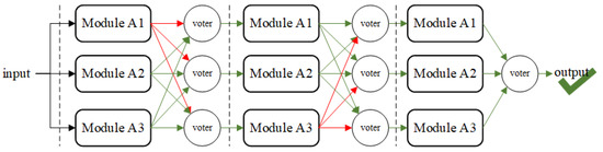
Conventional TMR designs can mask faults within a single redundant module. However, if multiple concurrent SEUs (marked with red arrows) trigger functional errors across several redundant modules, these errors accumulate and propagate through the circuit. Such accumulated errors would readily exceed the fault tolerance limits of conventional TMR implementations.
The system partitioning technique enhances HS-TMR implementation across circuit modules by deploying multiple staged voters within triplicated circuits, as shown in Figure 3. This partitioning isolates multiple SEUs and stops their propagation through the circuit, ensuring that, in most cases, the system will remain functional even if multiple redundant modules fail [11].
Figure 3.
Error mitigation of a partitioned HS-TMR design.
The system partitioning technique improves the soft error resilience of FPGAs in a very direct and obvious way. However, the additional resource consumption brought about is also serious, and it also increases the critical path length of the design, which brings negative timing effects. Too few partitions may not achieve the desired soft error resilience, and too many partitions may lead to performance degradation and excessive resource consumption. So, the optimal number of hierarchies needs to be explored to balance the area, performance, and reliability of the circuit.
5.2. State Synchronization
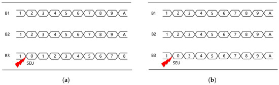
The state of the circuit is also vulnerable when SEUs strike. This is particularly true for sequential circuits with register feedback loops, even when the circuit is hardened using conventional TMR. However, if there is an error in one of the register feedback loops of the redundant module, the state of that module will not be continuously synchronized with the remaining two redundant modules. As shown in Figure 4a, an SEU strikes the next-state logic of redundant branch 3, causing its output to change from value 2 to value 0. The error continues to propagate, causing the state of the redundant branch 3 to remain out of synchronization with the other two branches. In this case, although the final voter is able to mask the incorrect value of that redundant branch, the reliability of the circuit is greatly reduced by the fact that the value of the third redundant branch is not synchronized, and an error in any of the two remaining redundant branches will cause the entire TMR circuit to fail.
Figure 4.
State change of a TMR design under an SEU: (a) without state synchronization; (b) with state synchronization.
Conventional netlist-level TMR methods, such as Precision Hi-Rel 2018.1 (Siemens EDA, Wilsonville, OR, USA), insert voters after all or most flip-flops [12]. Such a register-based voter insertion strategy can improve fault masking capability, but it also introduces a large number of redundant voters and therefore causes considerable area and timing overhead.
To solve the problem described above, we proposed a state synchronization technique, which can use the correct register values of the other two redundant branches to restore the registers of that branch affected by the SEUs to the correct state. Instead of inserting voters after all flip-flops, the proposed method only inserts synchronizing voters on the register feedback loops identified through graph analysis.
The key to the state synchronization technique is looking for register feedback loops in the design, which needs three steps: constructing DAGs, detecting feedback loops, and placing synchronizing voters.
5.2.1. Constructing DAGs
Locating register feedback loops directly in RTL netlists is considerably complex. It is more efficient to use graph-based representations for identifying such loops compared to code-form descriptions. So, the first step is generating DAGs from RTL netlists.
5.2.2. Detecting Feedback Loops
This research further reformulates the location of feedback loops in DAGs as the identification of Strongly Connected Components (SCCs) in graphs. The SCCs of a graph are the maximal subgraphs in which there is a path from each node to every other node. The definition of an SCC leads to the following corollaries [13]:
- Each SCC contains at least one cycle;
- No cycle spans more than one SCC;
- There are no cycles outside of the SCCs of a graph;
- Nodes not involved in any cycles will not be found in any SCC.
SCC decomposition is the process of finding all of the feedback loops in a graph, where DFS is applied to all nodes in the DAGs.
5.2.3. Placing Synchronizing Voters
Following the identification of all feedback loops, it is necessary to determine the optimal placement of the voter within the loop. This selection would critically impact circuit area and performance.
In this research, we proposed a heuristic method to minimize the length increment of the critical path. This method finds the logic path with the minimal delay between pairs of registers in the feedback loop, and inserts the voters at the end of the feedback loop.
5.3. Common Mode Errors
When the design is fully TMRed, no fault would occur except for a single voter from the netlist aspect. However, we further conducted fault injection testing on the TMR circuits on the FPGA board, and the result shows that many faults still exist. By doing fault localization and classification, we found that most of the faults are on the interconnects.
These specific failures stem from the design implementation. They differ from regular failures, which result from the inadequacy of the TMR. A single flipped configuration bit would affect multiple TMR branches simultaneously and cause circuit failure [14]. These failures are called Common Mode Failures (CMFs).
CMFs occur when TMR designs are implemented in FPGAs. This is due to the fact that multiple redundant branches of a TMR may be affected by the same configuration bit in the underlying architecture of the device. For example, the flip of a single configuration bit can cause shorts or opens in the interconnect lines, which may affect multiple TMR redundant branches or voter circuits. The presence of CMFs limits the possible maximum soft error resilience provided by TMR.
To reduce CMFs, we proposed a distributed layout technique based on the routing network. This technique physically separates and constrains the three redundant branches of the TMR circuit. However, forcibly separating these modules would impact the circuit’s timing performance. The separation distance affects both the performance and soft error resilience of the design. If the space between distributed branches is too small, critical resources shared between redundant branches may still trigger CMF. Conversely, too much space between circuits degrades timing performance.
We used the number of CLBs n to represent the space between the redundant branches, and introduced an evaluation function:
where is the timing performance metric of a TMR circuit with n CLBs between its distributed redundant branches. is the soft error resilience metric of an n-space TMR circuit. and are weighting factors, and would change according to actual demands. The more the timing performance is needed, the greater is. On the contrary, would be set to greater than 1 on the radiation-sensitive fields.
More specifically, the parameters and are normalized and mapped to by Equations (7) and (8), where is the value of the original , and is the value of the mapped .
In order to further testify the impact of parameters and on different strategies, a sensitivity study is performed. The experiment uses fft, fir, qsort and sobel from OpenFPGA benchmark as testcases. Strategies include one simplex version without TMR represented by SIMPLEX, one TMR version with unconstrained strategy represented by NOCON, and six TMR versions of different distributed placement strategies represented by 0CLB, 1CLB, 2CLB, 4CLB, 12CLB, and MAX.
As shown in Table 1, the timing metrics are measured using Xilinx Vivado 2020.2 (Xilinx, Inc., San Jose, CA, USA). The tolerance metrics are measured using the proposed dual-mode fault injection discussed in Section 7. The and of each testcase and configurations are also listed.
Table 1.
Timing, fault-tolerance, and evaluation parameters under different testcases and configurations.
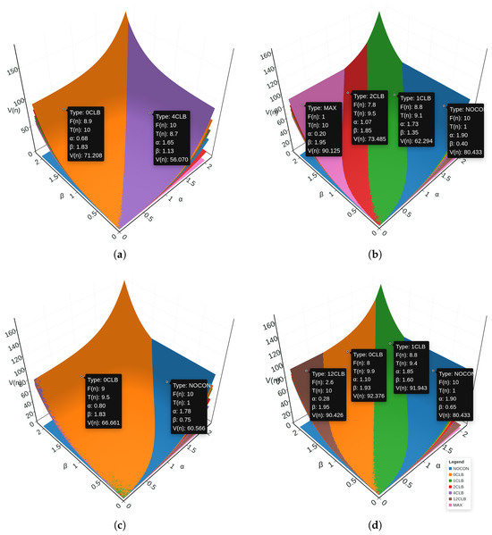
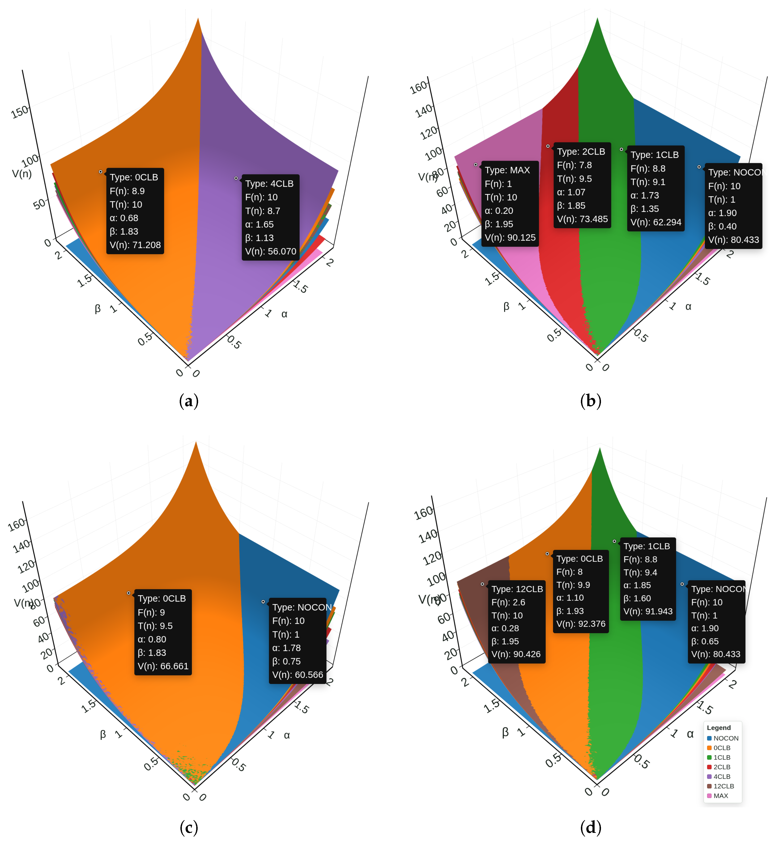
Based on abovementioned data, we plotted four graphs for each testcases to illustrate the relationship between , and , as shown in Figure 5.
Figure 5.
The maximum value of the evaluation function under different and values in (a) FFT, (b) FIR, (c) QSORT, (d) SOBEL testcases.
The maximum value and the corresponding and values in FIR (Figure 5b) and QSORT (Figure 5c) align with our intentions when designing the evaluation function in Equation (6). The greater is, the strategy with better timing performance is preferred, and the greater is, the strategy with better common mode error resistance is preferred.
However, on the FFT (Figure 5a) and SOBEL (Figure 5d) testcases, the strategy with better timing performance is preferred when is greater, but the strategy with better common mode error resistance is not preferred when is greater. This may be because the of different strategies in FFT and SOBEL testcases are very close, which makes the evaluation function more sensitive to the change of than .
In practice, we would suggest setting and to (1,1) as default setting, and (1,2) for radiation-sensitive fields, and (2,1) for performance-sensitive fields.
6. Static Hardening at Post-P&R Phase
After TMR and RT-SEM, the FPGA design acquires basic soft error resilience. However, this capability comes with huge PPA consumption. TMR has a very high overhead on area, power, and performance [15]. Several studies [16,17] have shown that synthesis-based approaches can mitigate the SEU issue while minimizing PPA overheads.
6.1. Idle Configuration Bits
After place and route, an FPGA design is described as a physical netlist. A physical netlist contains place and route information of the FPGA design, including the configuration bits of each LUT. According to research [17,18], there are a lot of idle configuration bits in LUTs, including unused configuration bits and don’t-care bits [19].
Unused configuration bits refer to the vacant input pins on the LUTs. As mentioned in [18], the number of LUTs where all inputs are fully used contributes only 37.43% of the total number of 6-LUTs. That is, more than 63% of the 6-LUTs have at least half of their configuration bits unused.
Don’t-care bits are bits that can not be accessed for any given circuit input or bits that do not affect the output of the circuit in any configuration value. However, soft errors will change the FPGA configurations and make don’t-care bits accessible and matter. So, it is necessary to care about these don’t-care bits in the discussion of soft errors.
The different configuration values of these idle configuration bits do not affect the circuit output under normal conditions. However, it would make a great difference in soft error resistance capabilities when soft errors occur. This difference inspires studies on error-resistance-oriented resynthesis.
6.2. Soft Error Probability of Configuration Bits
The first step of utilizing the idle configuration bits is to calculate the soft error probabilities. The soft error probability of a configuration bit is defined as follows:
where N is the input counts of the given circuit, is a given input pattern, is the primary output pattern of the input pattern , and is the primary output pattern of the input pattern when an SEU strikes on the configuration bit .
According to Equation (9), the soft error probability of a configuration bit is the probability that an error will occur in the primary output when an SEU strikes on that configuration bit. It follows that a configuration bit with a 0 soft error probability is a don’t-care bit. So, the location of the don’t-care bits can be found by a total soft error probability calculation.
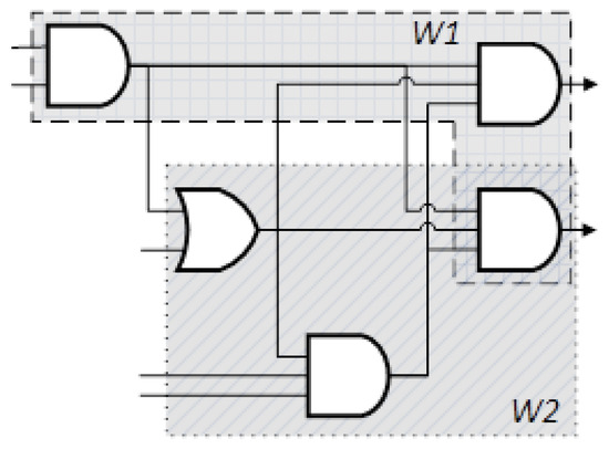
However, such calculations consume a huge amount of time, for the computational complexity increases exponentially with the number of inputs. In the proposed method, an improved windowing technique demonstrated in [20] is used. This technique partitions the circuit into multiple sub-circuits, reducing the N in Equation (9), with significantly less computational complexity.
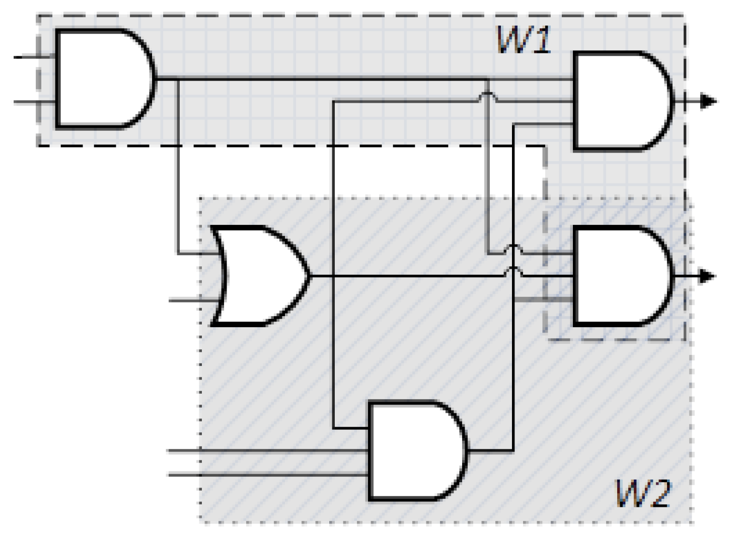
The don’t-care set calculated based on sub-circuits is the subset of the true don’t-care set. To ensure the coverage of the don’t-care bits set, the windowing technique uses three key features. First, the window grows using a heuristic input-bounded windowing technique that can maximize the window volume (defined as the number of nodes in the window) under a certain input bound. Second, the overlapping windows technique partitions the circuit into overlapped windows. So, a single LUT would be included in multiple overlapped windows and have several different don’t-care sets, as shown in Figure 6. Finally, the window grows in the simulation direction. These techniques can further improve the accuracy of the soft error behavior inside the sub-circuits.
Figure 6.
Sub-circuit of the windowing technique.
By calculating soft error probability, we can have a quantitative understanding of idle configuration bits and all other bits, which further guides the error-resistance-oriented resynthesis.
6.3. In-Place Duplication
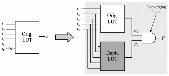
For LUTs in FPGAs, one unused input pin means half the configuration bits are vacant. Together with the dual-output LUT structure of the modern FPGAs, this vacancy could act as a redundancy.
Figure 7 shows a 6-LUT in Xilinx Virtex-7 FPGAs, which consists of two 5-LUTs, each connected to an output. In this case, an input of the 6-LUT is vacant. So, it is easy to copy the 32 used configuration bits into the 32 unused configuration bits, then select the type of converging logic according to the soft error probability of the configuration bit, and ultimately re-route the outputs of the converging logic into the original output.
Figure 7.
The basic idea of the In-Place Duplication algorithm.
6.4. In-Place Filling
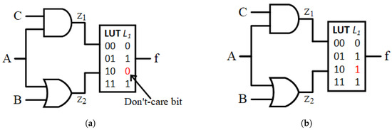
Don’t-care bits could also boost the FPGA soft error resilience. They usually occur with the reconvergence path, as shown in Figure 8a. The signal from A passes through two different paths , , and reconverges to one LUT. The configuration bit is a don’t-care bit and cannot be reached in the golden circuit. However, when the logic state of net or changes due to SEUs on their fan-in cone, the access to bit or would change to the access to bit , thus changing the logic state of output f. The circuit shown in Figure 8b has the same function and topology as the circuit in Figure 8a, but the output f is always correct under the aforementioned error. Thus, if don’t-care bits are preset properly, errors that happen in the fan-in cone of LUT can be masked inside .
Figure 8.
The basic idea of don’t-care-bit filling in the In-Place Filling algorithm: (a) a reconvergent structure in which the configuration bit for input pattern is a don’t-care bit (shown in red); (b) the same structure after filling the don’t-care bit with a proper logic value to mask propagated errors. A, B, and C are primary inputs, while and are internal signals.
As mentioned above, in an n-LUT, the don’t-care bits are configuration bits that would not be accessed under golden input vectors.
However, under SEUs, the access to don’t-care bits’ sibling bits (defined as the configuration bits that are 1 hamming distance away) would change to the access to the don’t-care bits themselves. So, by reconfiguring don’t-care bits to the logic state of their sibling bits, soft errors caused by the SEUs can be masked inside the n-LUT.
To minimize the overall soft error probability of the n-LUT, don’t-care bits inside n-LUTs should be reconfigured into the proper logic state. Table 2 shows the logic states and the soft error probability of all configuration bits in a 3-LUT. Configuration bit () is the don’t-care bit with 0 soft error probability. Configuration bits (), (), and () are its sibling bits and shaded in gray in the Table 2. In this case, the configuration bit () has the largest soft error probability, so the proposed method configures the don’t-care bit () into logic state .
Table 2.
The reconfiguration strategy for the don’t-care bit in a 3-LUT.
There are several issues with a single run of the aforementioned methods. First, the above procedures are heuristic and do not guarantee the optimal result. Second, the don’t-care set calculated based on the windows is the true subset of the actual don’t-care set. Finally, the reconfiguration of the current don’t-care set usually results in new don’t-care bits. So, to further optimize the result, iterative optimization is proposed. The procedures mentioned above would be executed several times until there are no more new don’t-care bits. Experiments show that stable results can be achieved with only several iterations.
Additionally, the AIP-SEM method only modifies LUT configuration bits, and would not change placement, routing resources, clocking structures, frame addressing, or any other device-level configuration bits. The bitstreams are generated after AIP-SEM, and do not affect implementation legality. So, the proposed method can be easily integrated into the conventional FPGA design flow.
7. Reliability Evaluation at Post-P&R Phase
When an FPGA design is hardened by the above technique, it is important to evaluate the soft error resilience. As mentioned above, current fault injection methods consume a lot of test time and have no support for the ICAP interface [21]. This research proposed a dual-mode JTAG/Serial fault injection methodology. To reduce the huge time consumption, we introduce a stochastic fault injection technique together with an MTBF model. To offer support for the ICAP interface, we introduce a novel fault injection method based on JTAG/Serial.
7.1. MTBF Model
The fault injection methodology proposed in this paper simulates the soft errors in the real environment, and records the number of faults injected into the design before the first occurrence of a fault. The actual MTBF is
where is the actual MTBF of the design i, is the number of faults injected before the first fault. is the time between two soft errors that occurred on the device, which is identical to one specific device in the specific test environment.
As is a constant in the given experimental conditions, we take as the measure of MTBF.
It should be noted that the above assumption is adopted for comparative evaluation under fixed experimental conditions, rather than for exact physical modeling of all radiation environments. In practical devices, different functional regions may exhibit different upset sensitivities due to architectural and physical non-uniformity, making the a complex function. A more fine-grained model incorporating variable will be considered in future work.
7.2. Stochastic Fault Injection Technique
In contrast to using traversal injection, the proposed method uses stochastic injection, which mimics the way soft errors actually occur. As a result, the proposed method significantly reduces the evaluation time of the fault injection tool by over 82%, facilitating quick feedback to other techniques mentioned above and speeding up the design cycle.
Additionally, to minimize the inaccuracy of the measured MTBF, the fault injection procedure above would be repeated 30 times for each design. The geometric mean of the 30 measured MTBFs will be used as the final MTBF. As a result, the relative error of the final MTBF between the stochastic injection and the traversal injection is less than 10%.
7.3. JTAG/Serial Dual-Mode
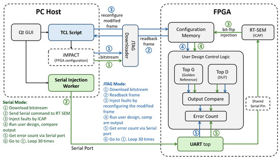
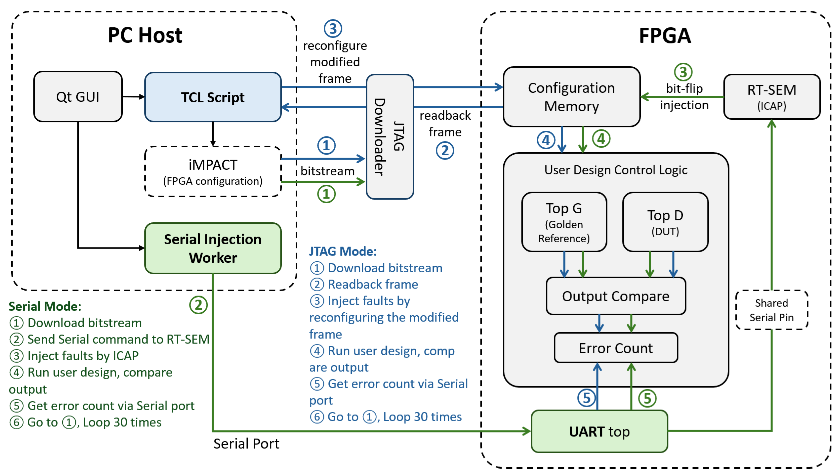
Figure 9 shows the system architecture and data flow of the proposed dual-mode JTAG/Serial fault injection method. This hardware–software co-design integrates the PC host and the FPGA evaluation board.
Figure 9.
The system architecture of the proposed dual-mode JTAG/Serial fault injection method.
The PC host is developed using Qt 5.12 (The Qt Company, Espoo, Finland), and executes fault injection control software that guides test sequences and monitors system responses. This layer interfaces with the hardware platform via a serial port and a JTAG downloader.
The evaluation board consists of multiple parts, including the user design control logic, the RT-SEM used for both injection and soft error mitigation, the UART logic and the on-chip resources. The user design control logic contains the device under test (DUT) circuit, the golden circuit, and the auto-comparison module. The RT-SEM can inject bit-flips using ICAP, which would not function with JTAG occupied. The UART logic handles the command from PC host, including the injection command for RT-SEM, the input generation for DUT and golden circuit, and the error count fetch.
The dataflow is also illustrated in Figure 9: the proposed dual-mode fault injection framework supports JTAG and Serial injection paths while sharing the same error detection mechanism. In the JTAG mode, the host first downloads the bitstream to the FPGA, then reads back the target configuration frame through JTAG, modifies the selected bit in software, and writes the modified frame back to the configuration memory to emulate a bit-flip. In the serial mode, the host sends injection commands to the RT-SEM module through the shared serial interface, and the RT-SEM module directly performs bit-flip injection into the configuration memory through ICAP. Although the injection mechanisms are different, both modes use the same user design control logic, output comparison module, and UART-based error counting path to evaluate the injected fault effect. Therefore, the proposed framework can flexibly switch between a JTAG-based injection and a Serial-based injection path, providing a unified and practical platform for fault injection experiments.
All circuits are physically implemented on an FPGA evaluation board providing measurement interfaces and instrumentation access points. This architecture enables the assessment of our proposed MSHE framework.
8. Experiment Results
The proposed method was implemented in C++ on Ubuntu 20.04. All experiments were performed on a workstation equipped with a 3.2 GHz Intel Core i7-12900K processor (Intel Corporation, Santa Clara, CA, USA) and 16 GB of memory. The testcases were selected from the OpenFPGA benchmark suite. The conventional FPGA EDA design flow shown in Figure 1 was completed using Xilinx ISE 14.7 (Xilinx, Inc., San Jose, CA, USA). For each testcase, the bitstream was generated by our scripts and deployed on an evaluation board equipped with a Xilinx XC7VX690T FPGA device (Xilinx, Inc., San Jose, CA, USA).
In this research, we chose Precision Hi-Rel (Mentor Graphics, Wilsonville, OR, USA) as the control group. The Precision’s TMR design used the distributed TMR (DTMR) mode, and the top-level input/output were configured as converge.
8.1. Soft Error Resilience
Table 3 summarizes the Mean Time Between Failures (MTBF) of various testcases under different soft error mitigation strategies. Compared to the original, unprotected designs, the full MSHE framework achieves a 243.79× improvement in system reliability. PrecisionTMR, used here as an industry baseline, achieves an average improvement of 13.33× over the original designs. This confirms its effectiveness in fault masking, although the improvement remains moderate in several benchmarks such as blowfish (4.81×) and loop (13.93×).
Table 3.
MTBF evaluation results of the proposed method (MTBF in hours).
Our proposed strategies show even greater gains. The combination of RT-SEM + TMR improves MTBF by an average of 206.01×, significantly surpassing Precision TMR by over 15×. This increase is primarily attributed to the integration of real-time configuration scrubbing, which effectively eliminates accumulated errors during runtime, a known limitation of traditional TMR.
The full framework (MSHE), which incorporates AIP into RT-SEM + TMR, further boosts the average MTBF to 243.79×. This corresponds to an additional 1.18× improvement over RT-SEM + TMR alone. While this gain is modest compared to the leap from Precision TMR, it demonstrates that AIP contributes additional soft error resilience, particularly in logic cones or LUT configurations that are not fully protected by TMR or runtime repair.
Interestingly, when AIP is applied in isolation, it achieves a 1.18× average MTBF improvement over the original, suggesting that its optimization effect is relatively lightweight. The marginal benefit of MSHE over RT-SEM + TMR implies that a portion of AIP’s optimization space overlaps with the protection already provided by TMR and scrubbing, highlighting some redundancy but also reinforcing the value of multi-tier hardening for edge-case faults.
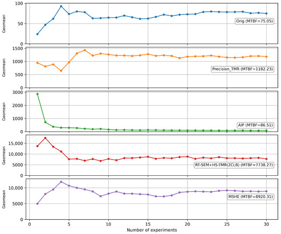
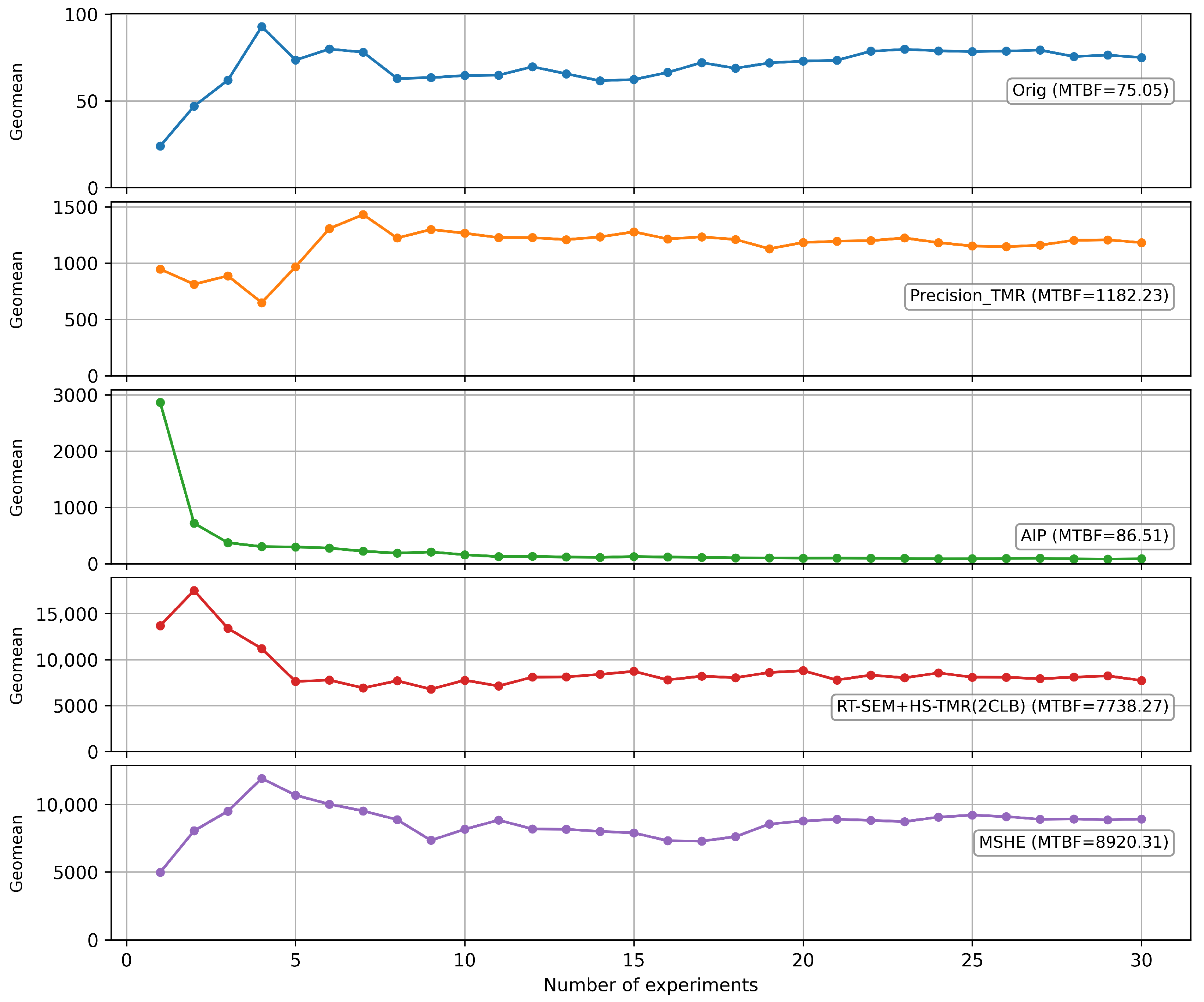
To further discuss the effectiveness of the stochastic fault injection method proposed in this paper, we tracked the geometric mean change in 30 fault injection runs on testcase gsm in Figure 10.
Figure 10.
A gsm example on number of experiments vs. geometric mean of MTBF in different mitigation strategies.
It should be noted that the stochastic fault injection method in this work exhibit substantial variability, for the fault injection procedure itself is random at the methodological level. In each run, the injected frame and bit are selected randomly from the candidate configuration space, and the experiment records the number of injections required before the first observable functional failure is detected. As a result, two runs with the same injection setup may yield very different numbers of injections before failure, depending on when highly sensitive bits are encountered. For this reason, the geometric mean is adopted as the primary summary metric, since it provides a more robust estimate of the random fault injection behavior. As shown in Figure 10, the geometric mean stables after 10~15 runs.
Nevertheless, the geometric mean does not fully capture the tail behavior of the distribution and may under-represent rare but significant deviations. Therefore, the reported MTBF values should be interpreted as a stable central tendency rather than an exact statistical expectation.
8.2. Resource Utilization
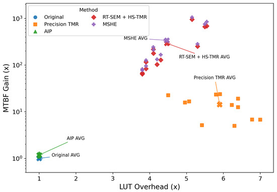
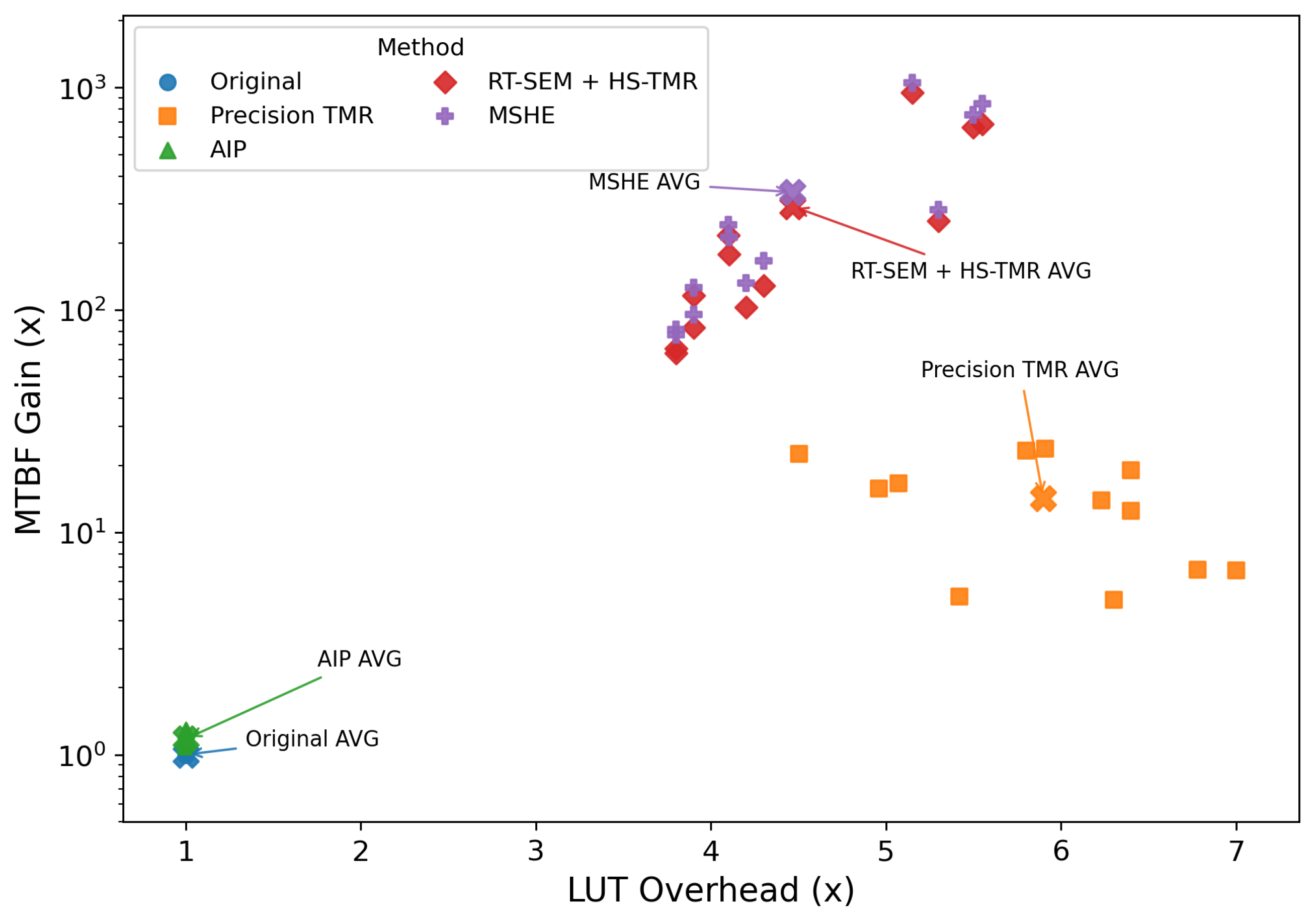
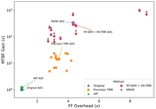
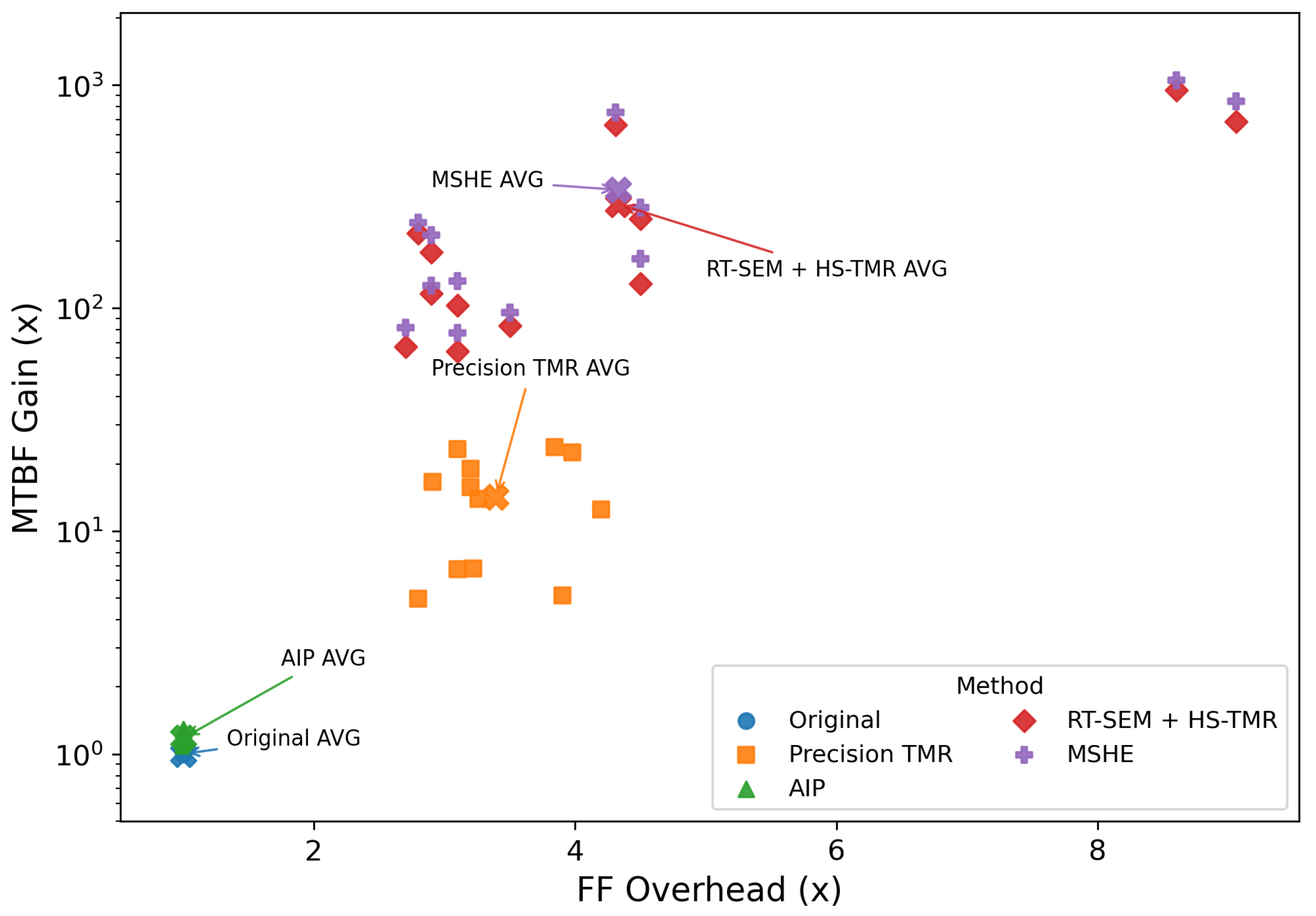
Table 4 shows the resource utilization across different mitigation strategies. In LUT utilization, our method (4.47×) demonstrates an advantage in LUT utilization compared to Precision Hi-Rel TMR (5.90×), indicating more efficient LUT implementation. However, the Flip-Flop (FF) utilization remains a relative disadvantage in our approach, with Precision TMR showing marginally better FF efficiency (3.39× vs. 4.33× average overhead). This suggests potential optimization opportunities in FF-heavy circuit designs.
Table 4.
Resource utilization under different mitigation strategies.
It is worth mentioning that the resource consumption between Original and AIP implementations is identical (both at 1.00× overhead). This validates AIP’s key advantage: providing enhanced reliability without additional hardware resource overhead. Similarly, the identical resource metrics between RT-SEM + HS-TMR and MSHE configurations (both at 4.47× LUT and 4.33× FF overhead) confirm that the MSHE implementation does not introduce additional hardware burden beyond the combined RT-SEM and HS-TMR techniques.
Also, the gap between HS-TMR and the RT-SEM + HS-TMR implementation exhibits a consistent incremental overhead pattern across diverse benchmarks, revealing the RT-SEM’s key operational principles. As shown in Table 4, the LUT utilization increases by a near-constant absolute value (average +418 LUTs) across diverse benchmarks, with minimal relative variation ( = ±204 LUTs). This growth suggests that RT-SEM functions as a fixed-resource module with error detection circuitry that imposes predictable hardware costs regardless of application complexity.
The resource utilization patterns further reveal distinct hardware overhead characteristics for each mitigation strategy. As shown in Table 4, AIP maintains identical LUT utilization to the original implementation (1.00× average overhead), demonstrating its hardware-transparent protection mechanism that imposes zero additional resource penalty through instruction-level hardening. In contrast, HS-TMR constitutes the dominant overhead component with 4.14× average LUT utilization increase, primarily implementing spatial redundancy through triple-replicated logic and voting circuits.
The observed resource trade-off mainly stems from the different optimization targets of the proposed framework. On the one hand, HS-TMR reduces LUT-intensive redundancy by avoiding straightforward netlist-level triplication and by applying hierarchy-aware partitioning and selective synchronization, while AIP-SEM introduces no additional hardware overhead. This leads to a clear reduction in LUT utilization compared with commercial TMR tools. On the other hand, the proposed framework relies more heavily on sequential structures, including feedback-state synchronization and RT-SEM runtime control logic, whose overhead is more likely to be reflected in flip-flop usage. As a result, the proposed method achieves lower LUT overhead but slightly higher FF overhead. This trade-off is intentional, since it exchanges part of the sequential resource cost for significantly improved reliability and lower logic-area pressure.
To further illustrate the trade-off between hardware overhead and reliability improvement, Figure 11 and Figure 12 plot the distributions of different mitigation strategies in terms of LUT overhead versus MTBF gain and FF overhead versus MTBF gain, respectively.
Figure 11.
LUT overhead vs. MTBF gain of different mitigation strategies. Cross markers denote the average results of the corresponding methods; the purple cross denotes the MSHE average.
Figure 12.
FF overhead vs. MTBF gain of different mitigation strategies. Cross markers denote the average results of the corresponding methods; the purple cross denotes the MSHE average.
It should be noted that two testcases, namely fft and loop, deviate largely from the average in the MTBF vs FF overhead distribution. For fft, the deviation is mainly attributed to the adopted TMR selective strategy, which leads to a resource–reliability trade-off that differs from the majority of the benchmarks. For loop, the deviation is mainly caused by the fixed hardware overhead introduced by RT-SEM in the proposed framework. Since the original loop design itself contains limited LUT and FF resources, adding a nearly fixed amount of hardening logic results in a disproportionately large normalized overhead.
8.3. Timing Results
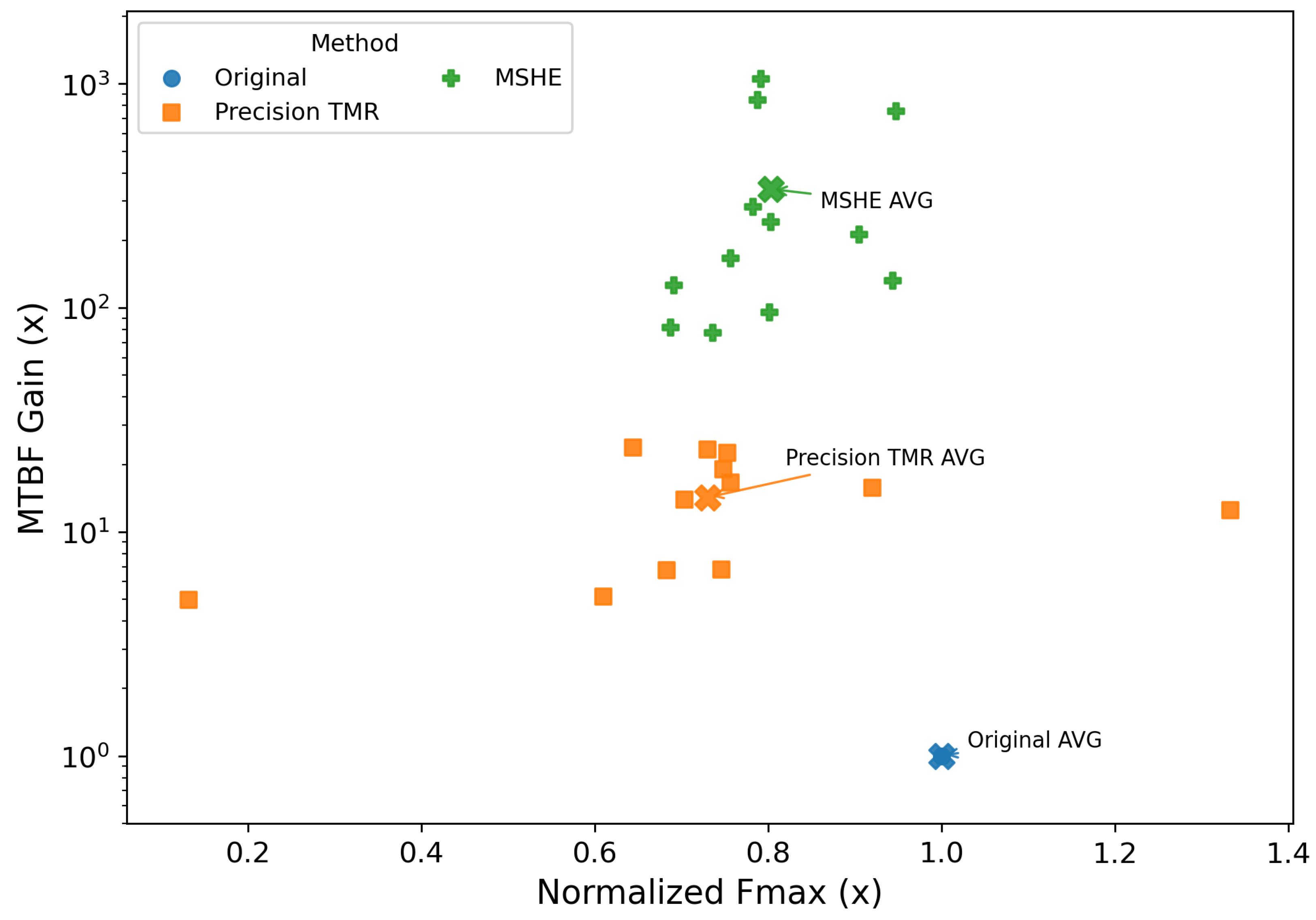
Table 5 analyzes the timing metrics, including the worst negative slack (WNS, in ns) and the maximum operating frequency (, in MHz), for various testcases under three configurations: Original, Precision TMR, and MSHE. The Fmax values of the Original configuration are normalized to 1.00×, while Precision TMR and MSHE configurations exhibit an Fmax at 0.73× and 0.80× of the Original, respectively.
Table 5.
Timing metrics under different mitigation strategies.
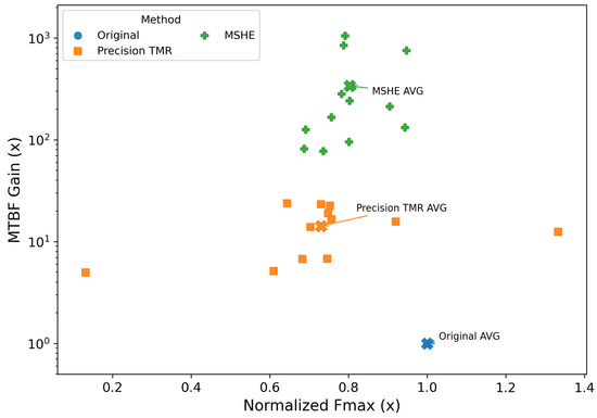
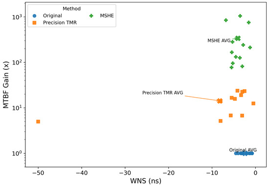
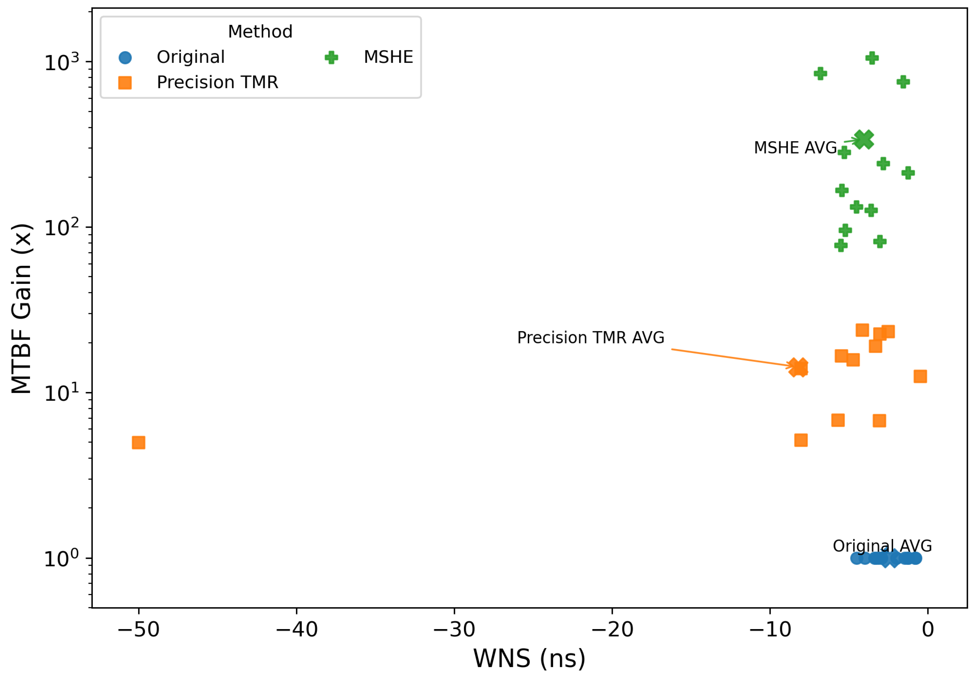
To better visualize the timing–reliability trade-off, Figure 13 and Figure 14 show the distributions of different mitigation strategies in terms of normalized versus MTBF gain and WNS versus MTBF gain, respectively. The Precision TMR provides moderate MTBF improvement with noticeable timing degradation, and records a relatively large deviation in testcase lowfish. By comparison, MSHE consistently achieves much higher MTBF gains while preserving better timing performance than Precision TMR. This tendency can be observed in both the normalized and WNS views. The average points further confirm that MSHE occupies a more desirable operating region, demonstrating that the proposed framework achieves superior reliability enhancement with a more balanced timing overhead.
Figure 13.
Fmax vs. MTBF gain of different mitigation strategies. Cross markers denote the average results of the corresponding methods; the green cross denotes the MSHE average.
Figure 14.
WNS vs. MTBF gain of different mitigation strategies. Cross markers denote the average results of the corresponding methods; the green cross denotes the MSHE average.
The proposed MSHE consistently outperforms Precision TMR across most testcases—for instance, in blowfish, MSHE improves from 19 MHz to 106 MHz, and in adpcm, from 83 MHz to 109 MHz. In general, MSHE offers a better balance between reliability enhancement and performance preservation in safety-critical systems.
9. Conclusions
This paper presented MSHE-SE, a comprehensive multi-tier spatiotemporal hardening framework for enhancing soft error resilience in SRAM-based FPGAs. Through synergistic integration of novel hardening techniques across the FPGA design flow, our framework addresses critical limitations of existing approaches while maintaining significantly reduced resource overhead.
In this paper, we propose a spatiotemporal hardening framework and evaluation method, MSHE-SE, powered by RT-SEM, HS-TMR, and AIP-SEM. Experimental results show that our framework achieves an average of 18.28× improvement in MTBF, while reducing LUT resource consumption by up to 45.7% compared to commercial TMR tools. The framework’s modular architecture allows selective deployment of hardening components based on criticality requirements, making it suitable for diverse applications from radiation-hardened systems to resource-constrained edge deployments.
In the future, there is still much research to be carried out about the MSHE-SE framework. Future work will concentrate on integrating reinforcement learning agents to dynamically optimize tunable parameters within algorithms like AIP-SEM. These agents will continuously analyze fault injection feedback and operational metrics to autonomously determine optimal values for critical parameters such as spatial separation distance N and weighting factors , in the evaluation function. This adaptive approach will further balance reliability, performance, and resource overhead without manual intervention.
Author Contributions
Conceptualization, Z.W.; Methodology, Z.W., Y.Z. and H.F.; Software, Z.W., Y.Z. and H.F.; Validation, Y.Z.; Formal analysis, Z.W.; Investigation, Z.W., X.Z. and H.F.; Resources, X.Z., S.W., Y.Z. and H.F.; Data curation, X.Z., C.T., Y.Z. and H.F.; Writing—original draft, Z.W.; Writing—review & editing, S.W., C.T. and J.Z.; Visualization, Z.W. and X.Z.; Supervision, S.W., J.Z. and L.C.; Project administration, S.W., C.T., J.Z. and L.C.; Funding acquisition, S.W., C.T. and L.C. All authors have read and agreed to the published version of the manuscript.
Funding
This work was supported in part by the National Nature Science Foundation of China (No. 62374138).
Data Availability Statement
The original contributions presented in this study are included in the article. Further inquiries can be directed to the corresponding author.
Acknowledgments
The authors would like to thank the reviewers for their valuable comments and suggestions.
Conflicts of Interest
Author Xiangyu Zhao was employed by the company China Aerospace Science and Technology Corporation. The remaining authors declare that the research was conducted in the absence of any commercial or financial relationships that could be construed as a potential conflict of interest.
Abbreviations
The following abbreviations are used in this manuscript:
| FPGA | Field Programmable Gate Array |
| SEU | Single Event Upset |
| TMR | Triple Modular Redundancy |
| PPA | Performance, Power, Area |
| MTBF | Mean Time Between Failures |
| RT-SEM | Real-Time Soft Error Mitigation |
| HS-TMR | Hierarchical and Synchronized TMR |
| AIP-SEM | Adaptive In-Place Soft-Error Mitigation |
| CRAM | Configuration RAM |
| LUT | Look-Up Table |
| ICAP | Internal Configuration Access Port |
| CMF | Common Mode Failure |
| DAG | Directed Acyclic Graph |
| DFS | Depth-First Search |
References
- Quinn, H.; Graham, P. Terrestrial-based radiation upsets: A cautionary tale. In Proceedings of the 13th Annual IEEE Symposium on Field-Programmable Custom Computing Machines (FCCM’05); IEEE: Piscataway, NJ, USA, 2005; pp. 193–202. [Google Scholar]
- Wang, W.; Li, X.; Chen, L.; Sun, H.; Zhang, F. A Review on Soft Error Correcting Techniques of Aerospace-Grade Static RAM-Based Field-Programmable Gate Arrays. Sensors 2024, 24, 5356. [Google Scholar] [CrossRef] [Scilit] [PubMed]
- Li, Z.; Qin, P.; Chai, R.; Hao, Y.; Zhang, D.; Li, H. FPGA-Based Reconfigurable System: Research Progress and New Trend on High-Reliability Key Problems. Electronics 2026, 15, 548. [Google Scholar] [CrossRef] [Scilit]
- Liu, Z.; Lu, Z.; Zhang, J.; Huang, L.; Yao, Z.; Lu, Z.; Zhang, J. Recent Advances on Reliability of FPGAs in a Radiation Environment. Microelectron. J. 2024, 148, 106176. [Google Scholar] [CrossRef] [Scilit]
- Morgan, K.S.; McMurtrey, D.L.; Pratt, B.H.; Wirthlin, M.J. A comparison of TMR with alternative fault-tolerant design techniques for FPGAs. IEEE Trans. Nucl. Sci. 2007, 54, 2065–2072. [Google Scholar] [CrossRef] [Scilit]
- Yaowei, Z. Research of Software Technology for Triple Modular Redundancy Based on High Level Synthesis. Master’s Thesis, China Academy of Launch Vehicle Technology, Beijing, China, 2022. [Google Scholar]
- Mousavi, M.; De, S.; Pourshaghaghi, H.R.; Corporaal, H. Fault tolerant fpgas: Where to spend the effort? In Proceedings of the 2019 22nd Euromicro Conference on Digital System Design (DSD); IEEE: Piscataway, NJ, USA, 2019; pp. 651–654. [Google Scholar]
- Feng, H.; Zhou, J.; Wang, S.; Wang, Z.; Li, J.; Bu, Y.; Tian, C. Real-Time Soft Error Mitigation System for SRAM-Based FPGAs. In Proceedings of the 2025 6th International Conference on Radiation Effects of Electronic Devices (ICREED), Yangzhou, China, 16–18 April 2025; pp. 1–4. [Google Scholar] [CrossRef] [Scilit]
- Xie, Y.; Qiao, T.; Xie, Y.; Chen, H. Soft Error Mitigation and Recovery of SRAM-based FPGAs using Brain-Inspired Hybrid-Grained Scrubbing Mechanism. Front. Comput. Neurosci. 2023, 17, 1268374. [Google Scholar] [CrossRef] [Scilit] [PubMed]
- Lai, V.; Diessel, O. ICAP-I: A reusable interface for the internal reconfiguration of Xilinx FPGAs. In Proceedings of the 2009 International Conference on Field-Programmable Technology, Sydney, Australia, 9–11 December 2009; pp. 357–360. [Google Scholar] [CrossRef] [Scilit]
- Kubica, M.; Czerwinski, R. Performance Testing of the Triple Modular Redundancy Mitigation Circuit Test Environment Implementation in Field Programmable Gate Array Structures. Appl. Sci. 2024, 14, 8604. [Google Scholar] [CrossRef] [Scilit]
- Siemens EDA. Precision Hi-Rel: Automated Triple Modular Redundancy (TMR) Synthesis Solution. Product Brief; Siemens EDA. 2020. Available online: https://static.sw.cdn.siemens.com/siemens-disw-assets/public/k3JFgxRC2D4AExfaV7JAI/en-US/Siemens-SW-Precision-Hi-Rel-82960-C1_1120.pdf (accessed on 26 April 2026).
- Johnson, J.M.; Wirthlin, M.J. Voter insertion algorithms for FPGA designs using triple modular redundancy. In Proceedings of the 18th Annual ACM/SIGDA International Symposium on Field Programmable Gate Arrays, Monterey, CA, USA, 21–23 February 2010; pp. 249–258. [Google Scholar]
- Cannon, M.J.; Keller, A.M.; Rowberry, H.C.; Thurlow, C.A.; Perez-Celis, A.; Wirthlin, M.J. Strategies for Removing Common Mode Failures From TMR Designs Deployed on SRAM FPGAs. IEEE Trans. Nucl. Sci. 2019, 66, 207–215. [Google Scholar] [CrossRef] [Scilit]
- Chen, L.; Zhang, Y.; Wang, S.; Zhou, J.; Tian, C.; Pang, Y.; Ma, X.; Zhou, C.; Du, Z. Key Technology and Development of Triple Modular Redundancy Tool for FPGA. J. Electron. Inf. Technol. 2022, 44, 2230–2244. [Google Scholar]
- Hu, Y.; Feng, Z.; He, L.; Majumdar, R. Robust FPGA resynthesis based on fault-tolerant Boolean matching. In Proceedings of the 2008 IEEE/ACM International Conference on Computer-Aided Design; IEEE: Piscataway, NJ, USA, 2008; pp. 706–713. [Google Scholar]
- Feng, Z.; Jing, N.; He, L. IPF: In-Place X-Filling Algorithm for the Reliability of Modern FPGAs. IEEE Trans. Very Large Scale Integr. (Vlsi) Syst. 2014, 22, 2226–2229. [Google Scholar] [CrossRef] [Scilit]
- Lee, J.Y.; Feng, Z.; He, L. In-place decomposition for robustness in FPGA. In Proceedings of the 2010 IEEE/ACM International Conference on Computer-Aided Design (ICCAD), San Jose, CA, USA, 7–11 November 2010; pp. 143–148. [Google Scholar] [CrossRef] [Scilit]
- Yu, T.; Chen, L.; Li, X.; Wang, S.; Zhou, J. A Software Controlled FPGA Fault Injection System Based Bitstream. Microelectronics 2017, 47, 553–556+561. [Google Scholar] [CrossRef]
- Cong, J.; Minkovich, K. LUT-based FPGA technology mapping for reliability. In Proceedings of the 47th Design Automation Conference, New York, NY, USA, 13–18 June 2010; DAC ’10. pp. 517–522. [Google Scholar] [CrossRef] [Scilit]
- Węgrzyn, M.; Kochan, O.; Maikiv, I. Fault Injection Tool for FPGA Reliability Testing: A Novel Method and Discovery of LUT-Specific Logical Redundancies. Electronics 2025, 14, 4600. [Google Scholar] [CrossRef] [Scilit]

Disclaimer/Publisher’s Note: The statements, opinions and data contained in all publications are solely those of the individual author(s) and contributor(s) and not of MDPI and/or the editor(s). MDPI and/or the editor(s) disclaim responsibility for any injury to people or property resulting from any ideas, methods, instructions or products referred to in the content. |
© 2026 by the authors. Licensee MDPI, Basel, Switzerland. This article is an open access article distributed under the terms and conditions of the Creative Commons Attribution (CC BY) license.