


Abstract
With the rapid advancement of digital integrated circuits, transistor sizes and integration levels have grown at an unprecedented rate, leading to increasingly complex design processes. A key challenge in digital layout design is the placement and routing of standard cell circuit layouts, which directly impact chip quality and performance. Power is a critical factor in evaluating standard cells. To enable low-power standard cell layouts, the depth-first search (DFS) algorithm is proposed to model and place the standard cell. Additionally, the study aims to satisfy Design Rule Checking (DRC), a grid routing strategy based on the deep reinforcement learning (DRL) algorithm, which quickly identifies cell boundaries and barriers such as existing nets as well as contacts, while optimizing metal routing to achieve minimal power. Results show that the standard cell layouts generated by the DRL-based model achieve over a 90% reduction in design time and approximately 5% improvements in power compared with manual layouts. The proposed method facilitates the rapid development of standard cell library and has important engineering value.
1. Introduction
Due to the large number and scale of transistors in digital circuits, electronic design automation (EDA) technology is usually needed to assist in the design and verification of digital integrated circuit layouts [1]. Standard cell layout plays a crucial role in computer design automation and is also an important topic in computer-aided design [2]. Its performance directly affects multiple performance indicators such as the area of the entire circuit layout, the delay and speed of logical cell data paths, the power consumption of the entire digital chip, and the temperature of the central area. Due to the increasing complexity of logical functions and the growing number of transistors in modern standard cell libraries, engineers often cannot seek the parameter limits of design. Instead, they tend to adopt conservative design rule constraints and cell reusability. However, such practices are frequently overly pessimistic as there is significant room for optimization in Performance, Power and Area (PPA) for standard cell layouts, particularly at advanced process nodes.
Standard cell design generally consists of two stages, namely placement and routing, each of which has its own optimization strategies. For placement problems, Hamiltonian circuits and Euler circuits applied in graph theory can also be used to solve the optimal distribution of device placements, making layout design more flexible and intelligent [3]. Routing technology, built upon well-structured placement, connects various circuit components through optimized wiring, aiming to minimize signal transmission delays and maximize circuit efficiency and performance [4]. Traditional optimization strategies, including graph theory-based methods and heuristic algorithms, have been widely applied to placement and routing optimization. For instance, the potential diffusion sharing between transistor pairs is modeled as a bipartite graph in [5]. In [6], the simulated annealing (SA) algorithm is employed to formulate transistor pairing and placement as an optimization problem to search for near-optimal solutions. The Euler-based layout planning algorithm is proposed in [7] to explore shortest routing paths. Moreover, Integer Linear Programming (ILP) and Boolean Satisfiability (SAT) techniques have been integrated into routing optimization frameworks to achieve globally optimal or near-optimal solutions [8,9].
With the rapid development of deep reinforcement learning, neural networks applied in the field of integrated circuit design are emerging one after another. In recent years, automated standard cell synthesis tools, including BonnCell [10] and NVCell [11], have demonstrated their capability to produce high-quality cell layouts for advanced technology nodes. However, a significant challenge remains: the generated placements for certain cells may suffer from routability issues, resulting in unroutable designs or layouts that cannot be routed without DRC errors. In [12,13], pin access and different layers have been optimized with a more dispersed distribution of pins, meaning that a larger pin access is more advantageous for the overall layout. The delay of logical cells and design rules was considered in [14]. Flow Capacity Control Constraint was adopted to store the S/D of FET as pins in Flow Capacity, which improves layout efficiency. The studies in [12,13,14] optimized the discrete standard cell layout, while the study in [15] optimized the overall layout of all macros. The use of graph neural network (GNN) embedding and feature extraction, convolution neural network (CNN) for global embedding and extraction of netlist dictionaries, and the Random Network Distillation (RND) algorithm were very innovative in [15]. Based on the powerful computing power of Google Computing Center, it is possible to achieve Google’ s own TPU design, with shortened chip design time, reaching or even surpassing the level of manual technology [16]. In [17], a combination of search tree- and CNN-based directional actions is leveraged to find routing solutions. The proposed framework in [18] simultaneously solves P&R for designing standard cell layout without deploying any sequential procedures by using dynamic pin allocation-based cell synthesis. While algorithm-driven automatic generation of standard cell layouts has been extensively researched for more than a decade, power optimization remains largely unexplored.
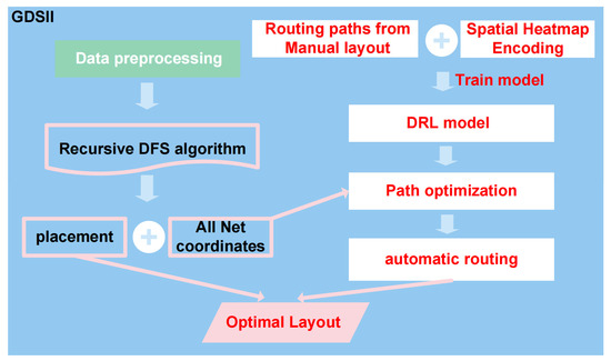
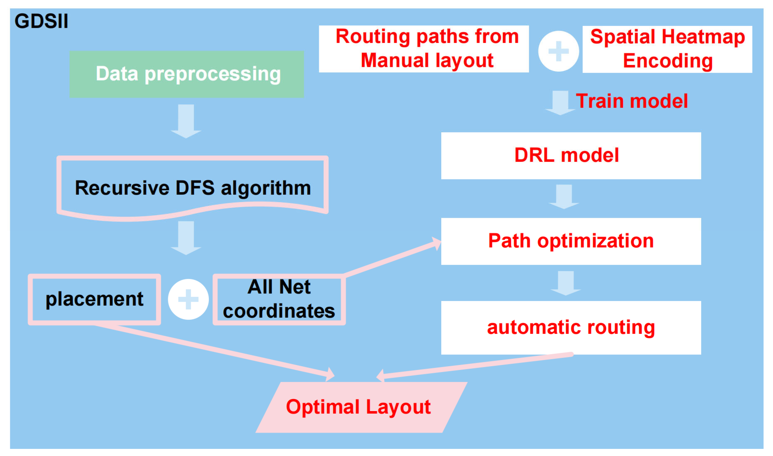
In this paper, a comprehensive framework for automated standard cell layout generation is proposed, as illustrated in Figure 1. First, a power-oriented placement strategy is employed to generate transistor coordinates and net connectivity information, providing a structured foundation for routing. Then, an efficient routing approach based on deep reinforcement learning (DRL) is developed to iteratively generate DRC-clean layouts under complex design rule constraints. By combining these components, the proposed framework significantly accelerates the design process while producing standard cell layouts with improved power efficiency compared to manual designs. The main contributions of this work are summarized as follows:
Figure 1.
The overall flow of framework.
- Power-Oriented Topological Placement via DFS: A specialized depth-first search (DFS)-based placement strategy is proposed for standard cell layout generation with a focus on power optimization. By maximizing source/drain sharing and gate alignment, the method effectively reduces routing metal length at the topological level. In addition, it extracts complete net coordinate information from the placement, providing a structured foundation for subsequent routing.
- Spatial Heatmap Encoding for Global Routing Awareness: A novel Spatial Heatmap Encoding scheme is introduced to enhance the representation capability of the routing environment. By encoding the local routing context into a multi-channel spatial representation, the proposed method enables the agent to capture both local structural information and global routing objectives. This mechanism significantly improves the model’s generalization ability and global routing capability.
- DRC-Clean Routing via Deep Reinforcement Learning: A deep reinforcement learning (DRL)-based grid routing framework is developed to handle complex design rule constraints. The model learns to avoid routing conflicts such as existing nets, contacts, and layout boundaries, enabling the generation of DRC-clean layouts with high success rate. This approach effectively transforms the power-oriented placement into a valid layout.
- Comprehensive Experimental Validation and Ablation Study: Extensive experiments are conducted across a wide range of standard cells under multiple PVT conditions. The results demonstrate that the proposed framework achieves over 5% power reduction and more than 90% reduction in layout generation time compared to manual design. In addition, ablation studies and comparisons with alternative strategies are conducted.
2. Analysis of Power Optimization in Standard Cell Layouts
The optimization of standard cell layouts from a power perspective involves several key aspects, including the limitations of manual layout, the consideration of design rules (DRs), and the selection of optimization algorithms. The following sections provide a detailed analysis of these three components.
Limitations of manual layout: Layout design involves fundamental trade-offs between area and power [19]. Layout designers prioritize cell area minimization and this technique often results in longer and more congested routing length. In standard cell layout, power line consumption remains relatively constant, and the power of the entire layout mainly depends on signal lines. Since the power of signal lines depends on net parasitic resistance, which increases with routing length, power efficiency can be significantly improved by implementing algorithms to minimize overall net length during placement.
Consideration for design rules (DRs): The most important thing in the process of designing a layout is to meet the design rules, which will directly determine whether the layout is effective [20]. For the issue, a cell canvas conforming to the process manufacturer’s specifications is constructed, with a fixed layout height, including grids satisfying the minimum spacing. The placement and routing information are then mapped onto the canvas using coordinates. It is also important to ensure that the canvas edges define the boundaries of the metal lines, preventing routing from extending beyond these boundaries.
Selection of optimization algorithms: Although traditional heuristic algorithms, such as simulated annealing (SA), and other intelligent optimization methods, such as A star algorithm, have been extensively developed and successfully applied to path planning problems [21], their effectiveness is limited in low-power standard cell layout routing. Routing is inherently a sequential task. While conventional algorithms often exhibit high local search efficiency, they tend to fail in finding feasible solutions when early routing decisions restrict the remaining routing space. This limitation primarily arises from insufficient global exploration capability [22,23,24]. To address this issue, a deep Q-network (DQN)-based model is adopted to compensate for this drawback. By leveraging routing paths from manual layouts as expert demonstrations and incorporating reward and penalty mechanisms, the intelligent agent can be trained to perform global routing more effectively.
3. Approach
For layout generation strategy, placement optimization and automatic routing model are considered in the framework. Specifically, the study uses recursive DFS algorithm to obtain the placement that achieves better power performance than manual layouts. Based on this, a grid-based routing strategy based on DQN is proposed to further generate layouts with improved overall performance compared to manual designs.
3.1. Placement Strategy
At advanced technology nodes, layout symmetry, particularly between NMOS and PMOS FETs, becomes critically important. An effective approach involves vertically aligning NMOS and PMOS transistors with matching gate connections into “sticks.” This stick formation method offers two key advantages: (1) it significantly reduces the total number of sticks, enabling placement completion within the original or even reduced area, and (2) it minimizes gate net routing length, which is a crucial first step for power optimization. These techniques constitute essential preprocessing steps before placement.
Since the source (S) and drain (D) terminals of MOS transistors are fixed, corresponding nets can be represented as nodes in a graph, with each MOS transistor modeling as a line segment. The entire cell can thus be represented as a directed graph, transforming the problem of finding the optimal placement into a graph-theoretical problem of identifying the longest path.
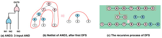
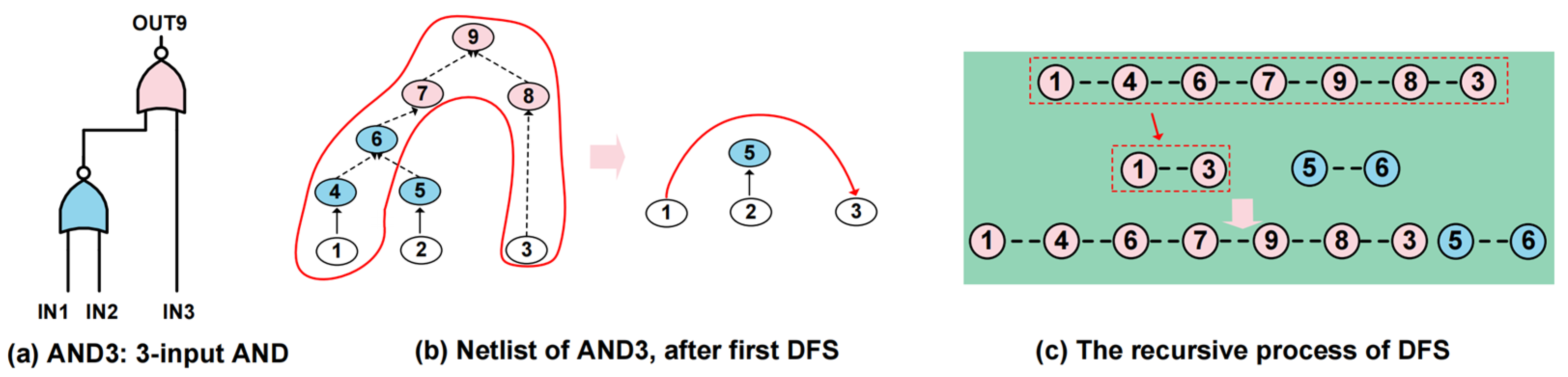
After preprocessing the MOS transistors, the connection information for the S, D, and G terminals of NMOS and PMOS transistors is stored in dictionaries in graphical form. The DFS algorithm is then applied to identify the longest connection path, which corresponds to the placement strategy maximizing source–drain sharing (SD_sharing) for the current cell. The endpoints of this path are extracted and compressed into a new cell, which is recursively processed using the DFS algorithm to generate the placement. This recursive process continues until all generated cells are reduced to discrete line segments. At this point, arranging the longest paths obtained from each iteration results in overall optimal placement. The schematic representation of the algorithm is provided in Figure 2a–c, taking a three-input AND cell as an example.
Figure 2.
Process of recursive DFS search.
Figure 3a,b presents the placement results. The algorithm executes in two key phases: (1) initial SD_sharing implementation for matched PN-FET pairs; (2) additional SD_sharing optimization to simultaneously improve area utilization and power efficiency. This placement above maximizes active area routing to minimize metal lengths, thereby reducing both parasitic resistance and overall power. The second step is exclusively applied to PN-FET pairs that fail to achieve SD_sharing in the first step, through which additional FETs can be obtained by disassembling individual PN-FET pairs. If the first step successfully enables SD_sharing for all PN-FETs, the resulting placement is already optimal and the second step is therefore unnecessary. As shown in Figure 3c,d, after placement optimization, the net coordinates to be routed are extracted and provided as inputs to the DQN model, which generates routing paths for each net. This procedure is described in detail in the next section.
Figure 3.
Diagram of placement and extracted coordinates.
3.2. Grid-Based Routing Strategy Based on DQN
The placement is derived under the objective of maximizing source/drain (DS) sharing among transistors, achieving better performance than manual layouts. While this strategy effectively reduces power, it also results in a highly compact arrangement of nets. Consequently, the routing space becomes extremely constrained, which significantly increases the complexity of the routing problem and limits the feasible solution space. Under such placements, conventional path planning strategies are prone to falling into local optima or encountering routing conflicts.
The routing problem of standard cells can theoretically be solved using DRL algorithms, where models are trained to explore different routing paths, and reward–punishment mechanisms based on design rules are used to impose constraints. This approach draws on manual routing techniques to achieve the shortest routing. Based on this insight, a DQN-based grid routing strategy is proposed, aiming to closely simulate the manual routing process.
To model the design rules defined in the PDK, spacing is determined based on the largest value among four parameters: the minimum width of metal layers, the minimum spacing between metal layers on the same layer, the minimum spacing between contacts, and the minimum spacing between metal layers and contacts. Additionally, the grid area is verified to ensure compliance with the design rule requirements for the minimum metal area. Routing is performed by default in a left-to-right traversal, connecting all points of the same net.
Moreover, although the routing order of nets may not be fixed, layout engineers intuitively account for how routing one net first affects the subsequent nets. Based on their experience, they prioritize nets in a way that makes the overall routing easier to complete. In the model, this process translates into optimizing a net’s path while also considering future steps. Specifically, when selecting the next path, it is not enough to simply avoid existing blockages, and the distance to already routed paths must also be factored in. For example, if the next position is close to the current one, it may be necessary to take a larger detour to avoid deadlocks and ensure a feasible route.
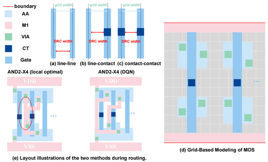
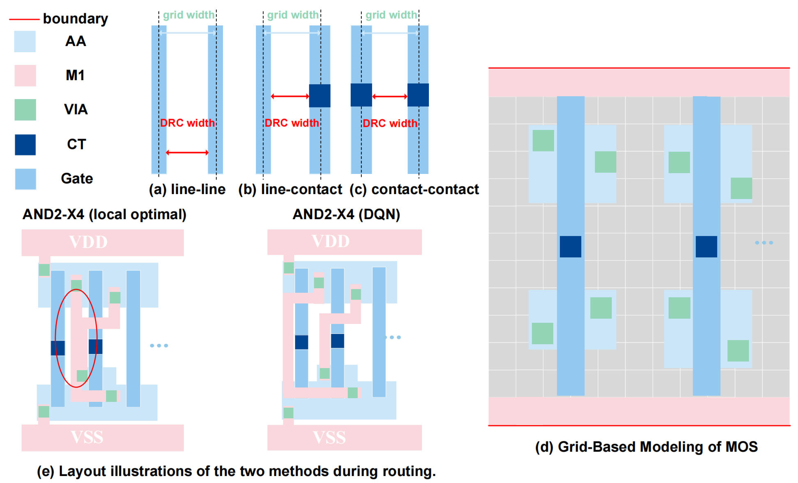
As illustrated in Figure 4a–c, the following spacing rules are considered when defining the routing canvas: line–line spacing, line–contact spacing and contact–contact spacing. The grid width must be larger than all widths specified by the design rules. The grid-based modeling of the MOSFET is illustrated in Figure 4d. The concept of an initial detour is introduced during the training of the DQN network, as shown in Figure 4e. When routing the upper middle net, the layout designer or traditional path-search algorithm such as A* typically selects the locally shortest path and directly connects the terminals. While this locally optimal solution minimizes the path length, it may reduce the available routing space for subsequent nets. In the illustrated case, when routing the lower net afterward, the spacing between existing wires becomes insufficient, resulting in a DRC violation. In contrast, the proposed DRL-based model has global routing capability. The agent learns to consider the impact of early routing decisions on later nets. As a result, the model introduces an initial detour when routing the upper net, leaving sufficient routing space for the lower net.
Figure 4.
Considerations for design rules: (a) DRC width between lines. (b) DRC width between line and contact. (c) DRC width between contacts. (d) Grid-based modeling of MOSFET. (e) Initial detour strategy of DQN model for avoiding DRC violations.
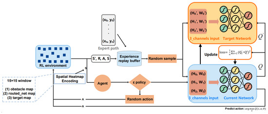
The action of AI agent is to move up, down, left, and right, and the state is the current position coordinate information. The action–value function Q(s, a) is approximated using a neural network. To enhance training stability, two neural networks are employed: a current network and a target network, denoted as Q(s, a; θ) and Q(s, a; θ−), respectively, where θ and θ− represent the parameters of the current and target networks. The current network selects the action a’ with the maximum Q value according to the current state s. The target network then evaluates this action and computes the corresponding Q value for action a′ in the next state st+1. The loss function L(θ) is constructed based on the difference between the Q value computed by the current network, Q(st, a; θ), and the target value estimated by the target network, r + γ max Q(st+1, a’; θ−). The parameters of the current network are updated using gradient descent. After the current network has been updated for a predefined number of steps, its parameters are synchronized to the target network to complete the target network update. The loss function is defined as follows:
L(θ) = E[(r + γ max Q(st+1, a’; θ−) − Q(st, a; θ))2]
During the training process, the extracted coordinate information is mapped onto a canvas to construct the reinforcement learning (RL) environment, which is represented as a 20 × 40 matrix initialized with zeros. To improve training stability and convergence speed, an experience replay mechanism is introduced. Complex net routing paths extracted from manual layouts are treated as expert demonstrations and stored in a replay buffer as training samples. Randomly sampled routing paths are fed into the target network and the current network, respectively. The neural network input is a three-channel tensor encoding three states: the current position of the agent, the locations already visited, and the target location. Each state is represented by a 20 × 40 matrix to describe spatial information, corresponding to the height (H) and width (W) of the canvas.
The neural network adopts a three-layer multi-layer perceptron (MLP) architecture with two hidden layers, each consisting of 64 neurons. The network outputs the Q values corresponding to available actions and is updated once per training iteration. During training, the parameters of the target network remain fixed, while only the current network is updated. After multiple training iterations, the agent is able to learn comprehensive routing strategies, thereby enhancing training robustness and accelerating network convergence.
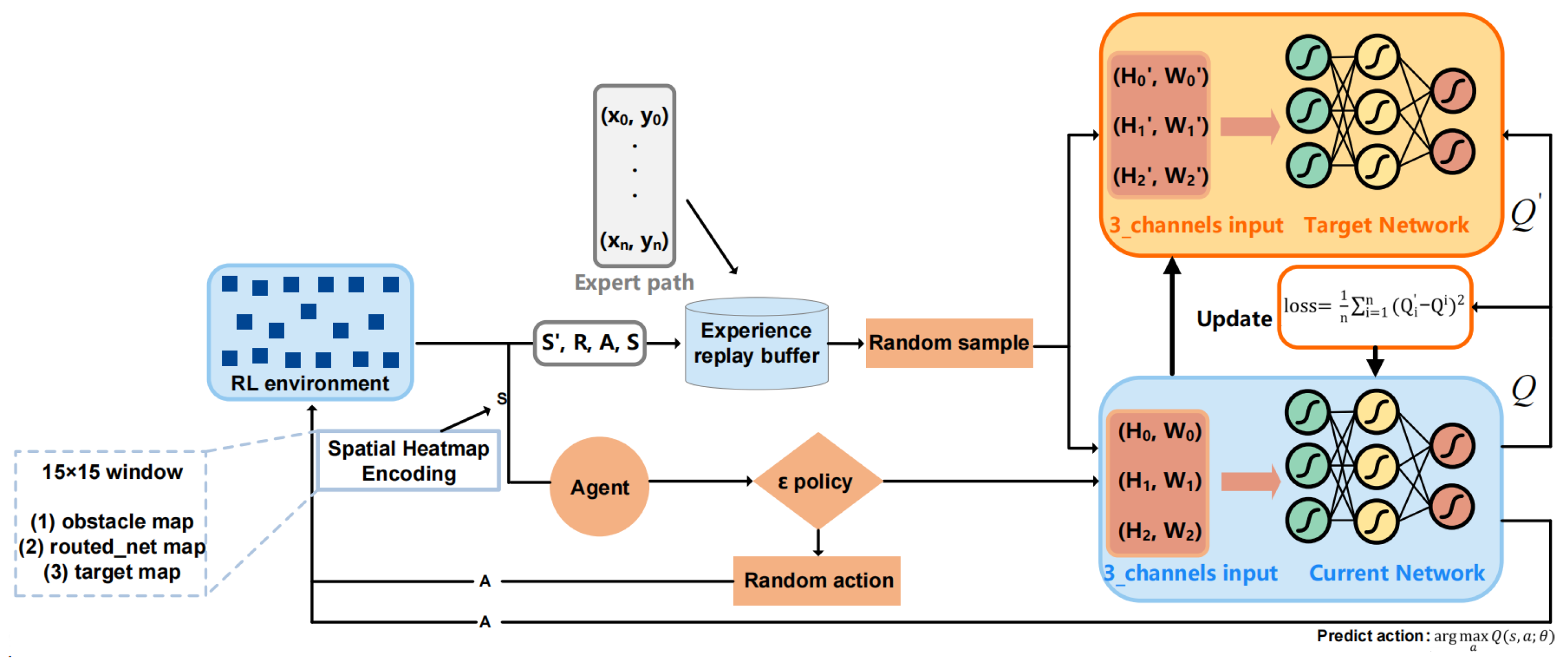
To balance exploration and exploitation, a ε—greedy policy is adopted for action selection. Specifically, an action is selected randomly with probability ε, while with probability 1 − ε, the action with the maximum Q value predicted by the current network is chosen. The overall framework of the reinforcement learning model is illustrated in Figure 5.
Figure 5.
Architecture of the proposed DQN model.
The reward mechanism is designed as follows: First, the distance between the current position and the next target position is calculated. Actions that move toward the target position receive positive rewards, while actions that move away from the target position are penalized. The reward magnitude is inversely proportional to the length of an individual net, implying that as the net length increases, the reward and penalty values gradually decay. The agent can be trained to develop global planning capability and enhance exploration for long routing paths. Successfully connecting a net yields a positive reward, while actions that cause collisions with obstacles during routing incur negative rewards. In addition, both rewards and penalties are dynamically adjusted. As the length of the routing path increases, the reward for reaching the next target position is progressively increased, while the penalty for obstacle collisions is relatively reduced.
To further enhance the global routing capability of the agent, a Spatial Heatmap Encoding mechanism is introduced during training. The state is encoded using a local-view representation centered at the agent’s current position. Specifically, a 15 × 15 window is cropped from the global grid, forming a three-channel input: (1) an obstacle map indicating blocked cells; (2) a routed net map representing the current routing status; and (3) a target map highlighting remaining connection points. In addition, four global features are concatenated, including the relative position to the target (∆x, ∆y), the normalized Manhattan distance, and the routing progress ratio. This representation enables the agent to capture local spatial structures while maintaining awareness of global routing objectives. The reward function is defined by introducing a heatmap-based modulation factor, which aligns local decision-making with global routing objectives:
where H(s) is a scalar modulation term derived from the spatial heatmap representation. Specifically, (dprev − dcurrent) measures the change in distance to the target, encouraging movements toward the goal. The term ∑Oij represents the obstacle density within the local window, penalizing regions with high congestion, while ∑Rij reflects the overlap with already routed paths, discouraging redundant routing. All heatmap-based quantities are aggregated into scalar values to ensure compatibility with the reward function. Max_growth denotes the difference between the total number of grid points and the initial number of routing grid points, representing the remaining available space. The reward for each step is defined as the difference between the number of grid points occupied by the current net (net_grid_num) and the total number of grid points (grid_total_num), normalized by dividing by the total grid points. This difference is then multiplied by the remaining space exponent and scaled by a factor of 0.1. The exponential term emphasizes compact routing solutions, while the heatmap modulation term further guides the agent to make spatially consistent decisions.
Max_growth = grid_total_num − initial_net_grid_num
Reward = max_growth(grid_total_num − net_grid_num)/max_growth/max_growth × 0.1 × (1 + λ × H(s))
Consequently, the proposed reward formulation bridges local spatial perception and global routing objectives. Through iterative training, the model is able to automatically complete routing tasks and generate layouts with improved compactness and reduced power consumption.
4. Experimental Results
4.1. Experimental Setup
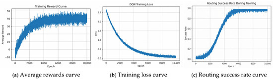
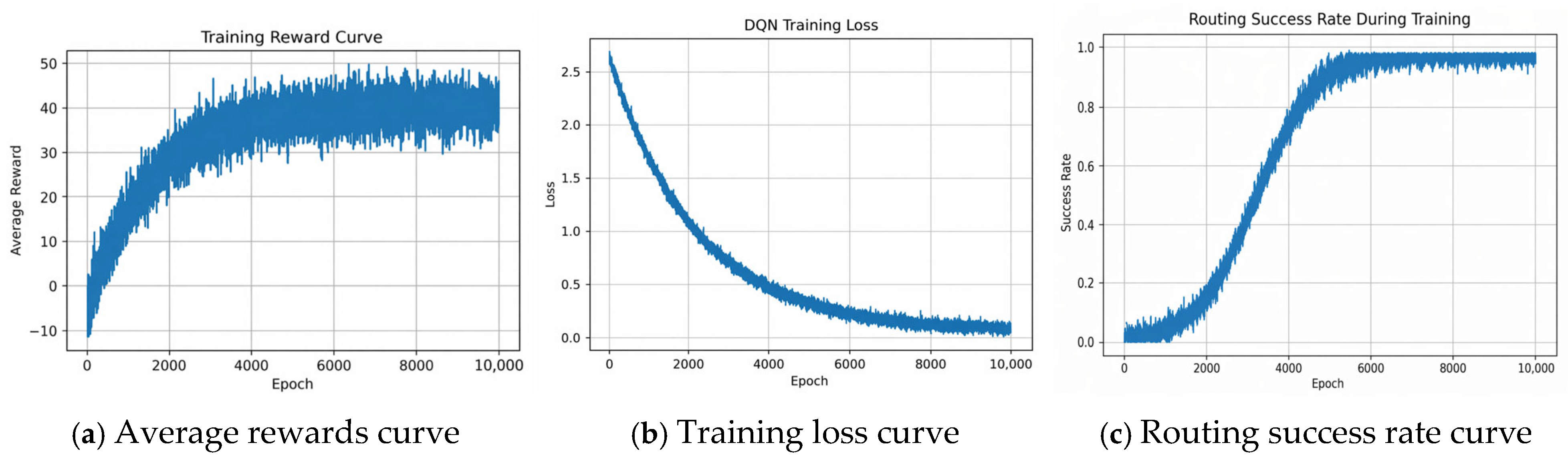
The program was validated using 28 nm PDK standard cell library under a given process, on an AMD Ryzen 7 5700X 8-Core CPU and an NVIDIA GeForce GTX 5060 GPU. The proposed algorithm is implemented using Pytorch (version 2.10.0). The whole learning and testing process is done in simulation environments created by Pycharm (version 2024.1). The DQN model is trained using a learning rate of 1 × 10⁻⁴ and a discount factor γ = 0.99. The replay buffer size is set to 50,000, and the mini-batch size for training is 64. A ε—greedy exploration strategy is adopted, where ε is initially set to 1.0 and gradually decayed to 0.05 during training. The average reward received during the learning process is illustrated in Figure 6a. The DQN network is trained by minimizing the error between the predicted Q value and the target Q value, which is defined in loss function (1). Figure 6b shows the training loss of the DQN network, demonstrating stable convergence behavior. The routing success rate is defined as the percentage of routing tasks in which the agent successfully connects the source and target nets without DRC violations, as shown in Equation (3). In the training process, each episode corresponds to a single routing task. To evaluate the learning progress of the agent, the success rate is calculated every 100 episodes as the ratio of successfully completed routing tasks. As training proceeds, the success rate gradually increases, indicating that the agent learns global routing capabilities to avoid obstacles and minimize routing cost.
Success Rate = Number of Successful Routes/Total Episodes
Figure 6.
Average reward curve, training loss curve and routing success rate curve during the learning process.
Figure 6c presents the routing success rate during training, which increases steadily as the model improves its routing decisions.
After the automatically generated layouts pass DRC and LVS verification, parasitic extraction (PEX) is performed to extract parasitic resistance and capacitance (R + C). The extracted parasitics are used to generate a DSPF post-layout netlist, which serves as the input for subsequent characterization. The standard cell library characterization was performed using Cadence Liberate (version 19.22.100) with the 28 nm PDK. Circuit-level simulations were carried out using the Spectre simulator. For the PVT corners, a total of 12 corners were considered. The process and voltage follows the foundry characterization corners, where the SS, TT, and FF corners correspond to supply voltages of 0.81 V, 0.9 V, and 0.99 V, respectively. Each process–voltage pair was further evaluated across four temperatures ranging from −40 °C to 125 °C, resulting in a total of 12 PVT corners. The input slew and output load correspond to the index_1 and index_2 parameters defined in the Liberty file, which consists of numerous 7 × 7 lookup tables. The corresponding index values used in this work are shown in Table 1.
Table 1.
The index_1 and index_2 parameters in lookup table.
4.2. Comparison with Other Techniques
The layouts generated by the proposed framework are evaluated through a comprehensive set of experiments. To highlight the global routing capability of the proposed DQN model and the effectiveness of the overall framework in power optimization, an ablation study is conducted. Specifically, the following configurations are compared: (1) the proposed full framework; (2) DQN routing without Spatial Heatmap Encoding; (3) layouts generated using simulated annealing (SA) for placement combined with DQN routing; (4) an SMT-based layout generation framework. The corresponding results are summarized in Table 2 and Table 3.
Table 2.
Layout results of part standard cells and comparison with other techniques.
Table 3.
Area and power results for selected standard cells and comparison with other techniques.
To ensure a fair comparison with the SMT-based approach, we strictly reproduce the framework described in [4]. The optimization priorities are defined as cell size, number of M2 tracks, and total metal length. The design rule constraints are modeled consistently with those used in the proposed DRL framework. Unlike the sequential placement–routing paradigm, the SMT method performs joint optimization of placement and routing, simultaneously determining (1) transistor placement (position and orientation), (2) routing topology for each net, (3) pin locations (including DPA-related configurations). Under the defined priorities, if no feasible solution is found, the SMT solver progressively relaxes constraints by increasing routing length, introducing M2 routing, and finally enlarging cell area. Representative standard cells are selected for evaluation using the SMT framework. Experimental results indicate that while SMT can efficiently generate layouts for simple cells, it exhibits several limitations when handling complex designs. First, SMT tends to rely more on M2 layer. Therefore, more metal tracks are introduced in the layout, including both M1 and M2 layers. Second, for complex cells, the runtime increases significantly, often exceeding one hour, and DRC-clean solutions are only obtained by sacrificing area. Third, due to the lack of initial detour strategies, the routing solutions show limited improvement in power optimization.
In contrast, the proposed DQN-based framework demonstrates strong generalization and global routing capability. Even for complex cells, it can efficiently generate DRC-clean layouts with improved power. Compared with the DQN routing model without Spatial Heatmap Encoding and expert demonstrations, the removal of these components significantly reduces the agent’s exploration capability. For cells with more than 15 FETs, the generated layouts already exhibit DRC violations. For more complex structures such as D flip-flops (DFFs), even the best results still contain up to six violations. For small-scale cells, the generated layouts achieve lower power consumption than manual, which indicates that power optimization is primarily determined by the placement structure rather than the DQN-based routing itself. In particular, layouts generated by the DFS-based placement can achieve power improvement regardless of the routing strategy employed.
In addition, the comparison between different placement strategies shows that layout structure has a direct impact on power consumption. When simulated annealing (SA) is used for placement (while keeping the routing method unchanged), both area and power are consistently higher than those obtained using the DFS-based placement. This is mainly because SA fails to fully exploit SD sharing opportunities, resulting in larger cell area, increased numbers of vias, and more metal tracks across routing layers. Consequently, the generated layouts exhibit higher power consumption compared with both manual designs and the proposed method.
These results demonstrate that the proposed framework effectively integrates placement and routing optimization toward low-power design, while the Spatial Heatmap Encoding training plays a critical role in enabling robust routing performance for complex standard cells. To evaluate the statistical robustness of the proposed reinforcement learning framework, we repeated each experiment 10 times with different random seeds and reported the mean and standard deviation of the results.
The experimental results indicate that, compared with manual layouts, the DQN model achieves over 5% reduction in power while maintaining same or even more optimal area.
Table 4 summarizes all the standard cells used in this work, categorized according to their functionality. The results present the performance of cells with different drive strengths within each category, including the best, worst, and average cases, as well as the total time required to generate the layouts for each cell type.
Table 4.
Summary of standard cells used in the experiments (80% of the library) and corresponding power statistics and runtime.
5. Conclusions
In this work, a novel methodology is proposed for the automatic generation of low-power standard cell layouts. First, a depth-first search (DFS)-based algorithm is applied to generating an optimal placement with low power. Based on the design rules defined in the process design kit (PDK), a grid-based canvas is constructed, onto which the optimized placement is mapped. Subsequently, a deep reinforcement learning model based on the deep Q-network (DQN) algorithm is trained to perform routing. To enhance global routing capability, a Spatial Heatmap Encoding scheme is introduced, which represents the routing environment using multi-channel spatial features. This enables the agent to capture local structural information while maintaining awareness of global routing objectives, thereby improving generalization across different net configurations. In addition, key routing paths extracted from manual layouts are incorporated into the experience replay buffer as expert demonstrations, further stabilizing training and accelerating convergence.
Experimental results demonstrate that the automatically generated standard cell layouts reduce generation time by more than 90% while achieving over 5% power optimization, and they consistently outperform traditional intelligent optimization algorithms, compared with manual layout. Future work will focus on extending the proposed approach to more complex cell architectures and emerging semiconductor technologies.
Author Contributions
Conceptualization, Z.L., B.L., Z.W. and W.L.; methodology, Z.L.; writing—original draft, Z.L.; writing—review and editing, B.L., Z.W., W.H. and C.Q. All authors have read and agreed to the published version of the manuscript.
Funding
This work was partially supported by the Guangdong S&T Programme, China (2022B0101180001), as well as partially by the Engineering Research Center of Design and Technology Co-Optimization of Integrated Circuits, Ministry of Education, China.
Data Availability Statement
The original contributions presented in the study are included in the article; further inquiries can be directed to the corresponding author.
Conflicts of Interest
The authors Wenchao Liu and Chaozheng Qin were employed by Guangzhou Primarius Electronic Technologies Co., Ltd., Guangzhou, China. The remaining authors declare that the research was conducted in the absence of any commercial or financial relationships that could be construed as a potential conflict of interest.
References
- Taylor, B.; Pileggi, L. Exact combinatorial optimization methods for physical design of regular logic bricks. In Proceedings of the Design Automation Conference (DAC), San Diego, CA, USA, 4–8 June 2007; pp. 344–349. [Google Scholar]
- Akiyama, T.; Nishizeki, T.; Saito, N. NP-Completeness of the Hamiltonian Cycle Problem for Bipartite Graphs. J. Inf. Process. 1980, 3, 73–76. [Google Scholar]
- Scheffer, L.; Lavagno, L.; Martin, G. EDA for IC System Design, Verification, and Testing. In Electronic Design Automation for Integrated Circuits Handbook; CPU Design Answers to Frequently Asked Questions; CRC Press: Boca Raton, FL, USA, 2006; Volume 16, pp. 127–151. [Google Scholar]
- Lee, D.; Park, D.; Ho, C.-T.; Kang, I.; Kim, H.; Gao, S.; Lin, B.; Cheng, C.-K. SP&R: SMT-based simultaneous Place-and-route for standard cell synthesis of advanced nodes. IEEE Trans. Comput.-Aided Des. Integr. Circuits Syst. (TCAD) 2020, 40, 2142–2155. [Google Scholar]
- Hwang, C.-Y.; Hsieh, Y.-C.; Lin, Y.-L.; Hsu, Y.-C. A fast transistor-chaining algorithm for CMOS cell layout. IEEE Trans. Comput.-Aided Des. Integr. Circuits Syst. (TCAD) 1990, 9, 781–786. [Google Scholar] [CrossRef] [Scilit]
- Lu, A.; Lu, H.-J.; Jang, E.-J.; Lin, Y.-P.; Hung, C.-H.; Chuang, C.-C.; Lin, R.-B. Simultaneous transistor pairing and placement for CMOS standard cells. In Proceedings of the 2015 Design, Automation & Test in Europe Conference & Exhibition (DATE), Grenoble, France, 9–13 March 2015; pp. 1647–1652. [Google Scholar]
- Riepe, M.A.; Sakallah, K.A. Transistor placement for noncomplementary digital VLSI cell synthesis. ACM Trans. Des. Autom. Electron. Syst. (TODAES) 2003, 8, 81–107. [Google Scholar] [CrossRef] [Scilit]
- Cortadella, J.; Petit, J.; Gómez, S.; Moll, F. A Boolean Rule-Based Approach for Manufacturability-Aware Cell Routing. IEEE Trans. Comput.-Aided Des. Integr. Circuits Syst. (TCAD) 2014, 33, 409–422. [Google Scholar] [CrossRef] [Scilit]
- Lu, H.-J.; Jang, E.J.; Lu, A.; Zhang, Y.T.; Chang, Y.H.; Lin, C.H.; Lin, R.B. Practical ILP-based routing of standard cells. In Proceedings of the 2016 Design, Automation & Test in Europe Conference & Exhibition (DATE), Dresden, Germany, 14–18 March 2016; pp. 245–248. [Google Scholar]
- Van Cleeff, P.; Hougardy, S.; Silvanus, J.; Werner, T. BonnCell: Automatic Cell Layout in the 7-nm Era. IEEE Trans. Comput.-Aided Des. Integr. Circuits Syst. (TCAD) 2020, 39, 2872–2885. [Google Scholar] [CrossRef] [Scilit]
- Ren, H.; Fojtik, M. Nvcell: Standard cell layout in advanced technology nodes with reinforcement learning. In Proceedings of the ACM/IEEE Design Automation Conference (DAC), San Francisco, CA, USA, 5–9 December 2021; pp. 1291–1294. [Google Scholar]
- Xu, X.; Yu, B.; Gao, J.-R.; Hsu, C.-L.; Pan, D.Z. PARR: Pin access planning and regular routing for self-aligned double patterning. ACM Trans. Des. Autom. Electron. Syst. (TODAES) 2016, 21, 1–21. [Google Scholar]
- Cheng, C.-K.; Ho, C.-T.; Lee, D.; Lin, B.; Park, D. Complementary FET (CFET) Standard Cell Synthesis Framework for Design and System Technology Co-Optimization Using SMT. IEEE Trans. Very Large Scale Integr. (VLSI) Syst. 2021, 29, 1178–1191. [Google Scholar] [CrossRef] [Scilit]
- Yu, T.-C.; Fang, S.-Y.; Chiu, H.-S.; Hu, K.-S.; Tai, P.H.-Y.; Shen, C.C.-F.; Sheng, H. Pin accessibility prediction and optimization with deep learning-based pin pattern recognition. In Proceedings of the 56th Annual Design Automation Conference (DAC), Las Vegas, NV, USA, 2–6 June 2019; pp. 1–6. [Google Scholar]
- Cheng, R.; Yan, J. On Joint Learning for Solving Placement and Routing in Chip Design. Neural Inf. Process. Syst. 2021, 34, 16508–16519. [Google Scholar]
- Mirhoseini, A.; Goldie, A.; Yazgan, M.; Jiang, J.W.; Songhori, E.; Wang, S.; Lee, Y.-J.; Johnson, E.; Pathak, O.; Nazi, A.; et al. A graph placement methodology for fast chip design. Nature 2021, 594, 207–212. [Google Scholar] [CrossRef] [Scilit] [PubMed]
- Lee, T.-C.; Yang, C.-Y.; Li, Y.-L. iTPlace: Machine Learning-Based Delay-Aware Transistor Placement for Standard Cell Synthesis. In Proceedings of the 2020 IEEE/ACM International Conference On Computer Aided Design (ICCAD), San Diego, CA, USA, 2–5 November 2020; pp. 1–8. [Google Scholar]
- Park, D.; Lee, D.; Kang, I.; Gao, S.; Lin, B.; Cheng, C.-K. SP&R: Simultaneous Placement and Routing framework for standard cell synthesis in sub-7nm. In Proceedings of the 2020 25th Asia and South Pacific Design Automation Conference (ASP-DAC), Beijing, China, 13–16 January 2020; pp. 345–350. [Google Scholar]
- Ho, C.-T.; Ren, H. Large Language Model (LLM) for Standard Cell Layout Design Optimization. In Proceedings of the IEEE LLM Aided Design Workshop (LAD), San Jose, CA, USA, 28–29 June 2024; pp. 1–6. [Google Scholar]
- Gao, X.; Zhang, H.; Pan, Z.; Lin, Y.; Wang, R.; Huang, R. Migrating Standard Cells for Multiple Drive Strengths by Routing Imitation. In Proceedings of the 2024 2nd International Symposium of Electronics Design Automation (ISEDA), Xi’an, China, 10–13 May 2024; pp. 5–10. [Google Scholar]
- Jo, K.; Ahn, S.; Do, J.; Song, T.; Kim, T.; Choi, K. Design Rule Evaluation Framework Using Automatic Cell Layout Generator for Design Technology Co-Optimization. IEEE Trans. Very Large Scale Integr. (VLSI) Syst. 2019, 27, 1933–1946. [Google Scholar] [CrossRef] [Scilit]
- Wu, N.; Li, Y.; Hao, C.; Dai, S.; Yu, C.; Xie, Y. Gamora: Graph learning based symbolic reasoning for large-scale boolean networks. In Proceedings of the 2023 60th ACM/IEEE Design Automation Conference (DAC), San Francisco, CA, USA, 9–13 July 2023; pp. 1–6. [Google Scholar]
- Lu, Y.-C.; Nath, S.; Khandelwal, V.; Lim, S.K. Rl-sizer: VLSI gate sizing for timing optimization using deep reinforcement learning. In Proceedings of the 2021 58th ACM/IEEE Design Automation Conference (DAC), San Francisco, CA, USA, 5–9 December 2021; pp. 733–738. [Google Scholar]
- Alioto, M.; Scotti, G.; Trifiletti, A. A novel framework to estimate the path delay variability on the back of an envelope via the fan-out-of-4 metric. IEEE Trans. Circuits Syst. I Regul. Pap. 2017, 64, 2073–2085. [Google Scholar] [CrossRef] [Scilit]



Disclaimer/Publisher’s Note: The statements, opinions and data contained in all publications are solely those of the individual author(s) and contributor(s) and not of MDPI and/or the editor(s). MDPI and/or the editor(s) disclaim responsibility for any injury to people or property resulting from any ideas, methods, instructions or products referred to in the content. |
© 2026 by the authors. Licensee MDPI, Basel, Switzerland. This article is an open access article distributed under the terms and conditions of the Creative Commons Attribution (CC BY) license.