


Abstract
In this article, a compact wideband three-slot filtering antenna is proposed. The antenna consists of a U-shaped driven slot, a folded resonant slot, and a linear resonant slot. A microstrip feedline with a shorting via is employed to excite the antenna. Mixed electric and magnetic couplings enable the driven slot to couple to the two resonant slots. Three resonant frequencies lie within the passband, resulting in wideband operation. The lowest resonant frequency is determined by the folded resonant slot, while the highest resonant frequency is determined by the linear resonant slot. The center resonant frequency is influenced by the combined effects of the U-shaped driven slot, the folded resonant slot, and the linear resonant slot. A low-frequency radiation null at 1.68 GHz and a high-frequency radiation null at 3.19 GHz are generated. These two radiation nulls enable the proposed antenna to achieve excellent filtering performance. A prototype was fabricated and measured. The measured results are in good agreement with the simulated ones. The measurements show that the proposed three-slot filtering antenna exhibits a relative impedance bandwidth of 39.1%. The out-of-band suppression levels reach 12.5 dB and 14.8 dB in the lower and upper sidebands, respectively. The proposed three-slot filtering antenna is suitable for applications in wireless communication systems.
1. Introduction
As an important component in radio frequency front-ends, the integration of antennas and filters contributes to reducing the complexity of wireless devices. In recent years, filtering antennas have attracted considerable research attention. These antennas have the ability to simultaneously fulfill both filtering and radiating functions, effectively suppressing out-of-band interference signals.
Design methods for filtering antennas are generally categorized into three types. The first approach is to directly cascade an antenna with a filter [1,2,3,4]. Impedance matching networks are employed to ensure optimal impedance matching between the antenna and the filter, facilitating their effective cascaded integration. However, this approach increases the overall volume of the antenna system. Additional insertion loss is introduced by the filter and the impedance matching network. The second approach replaces the final stage of a conventional filter with a radiation unit [5,6,7,8]. This method reduces device complexity to some extent, but the remaining filtering network still results in additional insertion loss. The third approach adopts a fusion integration scheme that eliminates the need for an independent filter. In this design, radiation nulls are introduced by loading parasitic patches [9,10,11], etching slots [12,13,14], building extra coupling paths [15,16], and loading shorting pins [17,18], which enables efficient suppression of out-of-band signals. Without the extra filter, this approach exhibits distinct advantages, including high integration, low insertion loss, and a simplified structural configuration. These advantages are highly desirable for the development of compact wireless communication systems.
In scenarios such as tunnels, streets, and highways, bidirectional radiation antennas are more suitable. They can cover signal transmission in two opposite directions. Slot antennas can realize bidirectional radiation. However, they are limited by a narrow operating bandwidth. Several filtering slot antennas have been proposed [19,20,21]. In [19], the final stage of a filter is replaced with a slot antenna. A filtering response is achieved by introducing radiation nulls through loading parasitic elements [20,21]. Nevertheless, these antennas still exhibit constrained bandwidth performance, failing to meet the requirements of wideband communication systems. Given these limitations, there is an urgent need to propose a compact, wideband filtering slot antenna. This design is intended to address the challenges of miniaturization, integration, and wideband operation.
In this article, a compact wideband three-slot filtering antenna is proposed. Two resonant slots are introduced to generate three resonant frequencies, effectively expanding the operating bandwidth. Meanwhile, mixed electric and magnetic couplings between the driven slot and resonant slots introduce two radiation nulls, which realize excellent filtering performance. The three resonant frequencies of the proposed antenna support 5G NR bands n7, n39, and n41, making its great potential for modern wideband wireless systems. The fundamental distinction between this design and previously reported filtering slot antennas lies in its unique mixed electric and magnetic coupling topology. This coupling topology enables the excitation of three resonant frequencies to achieve wideband operation. The main novel contributions of this work are further summarized as follows:
- A mixed electric and magnetic coupling topology for slot antennas is proposed, serving as a new design approach for wideband operation and filtering performance.
- Wideband operation with a 39.1% relative impedance bandwidth is achieved by exciting three resonant frequencies via the mixed coupling topology.
- High-selectivity filtering performance with two radiation nulls is realized through the mixed electric and magnetic couplings between the slots.
- A highly compact integrated design is achieved without additional filtering circuits or impedance matching networks.
The article is structured as follows. Section 2 analyzes three different coupling cases between two slots, inspiring the design approach for the filtering antenna. Section 3 details the antenna design process and operating principles. The radiation mechanism is analyzed through the electric field distributions. The equivalent magnetic currents are employed to illustrate the filtering mechanism. In Section 4, a prototype of the antenna was fabricated and measured. The measured results indicate that the proposed three-slot filtering antenna achieves a relative impedance bandwidth of 39.1%. The out-of-band suppression levels exhibit superior performance. Furthermore, a comparative analysis with other designs shows that the proposed three-slot filtering antenna exhibits distinct advantages in terms of compact size, wide bandwidth, and integrated filtering performance. Finally, Section 5 summarizes the conclusions of this article.
2. Design Principle
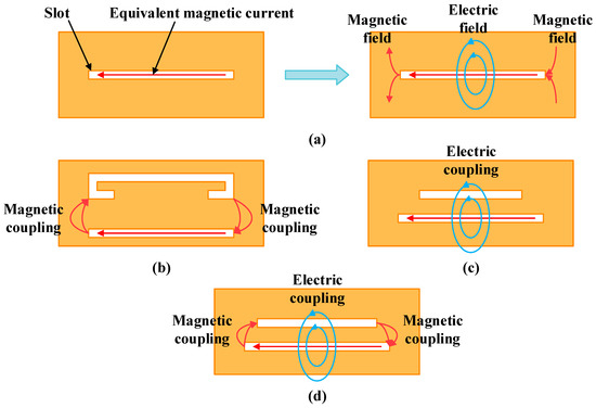
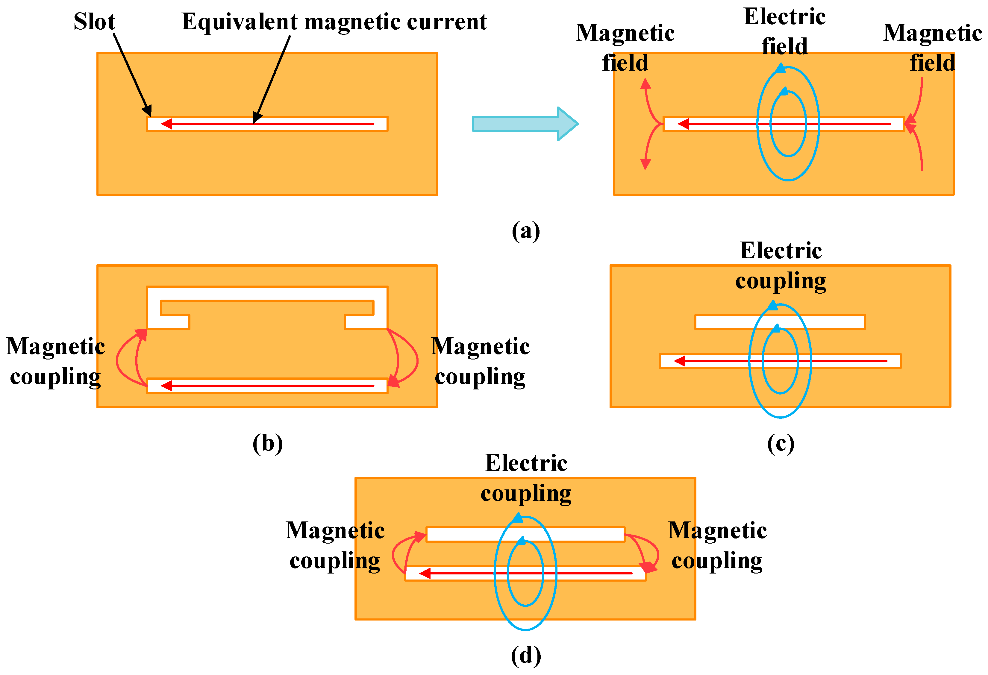
Figure 1 depicts the electric and magnetic field distributions around the slot antenna and three coupling cases between two slots. In Figure 1a, the electric field is dominant in the middle region of the slot, while both ends are dominated by the magnetic field. In Figure 1b, both ends of the folded slot are closer to both ends of the linear slot than to its middle section. Thus, magnetic coupling acts as the main coupling mechanism between the slots. In Figure 1c, a shorter slot is placed parallel to and in close proximity to the middle section of the longer slot. The electric field exhibits a higher intensity than the magnetic field in the middle region, making electric coupling dominant between the two slots. In Figure 1d, electric and magnetic couplings can exist simultaneously. Magnetic coupling is relatively weak when both ends of the two slots are far apart, and its strength increases as these ends become closer to each other. In this case, the electric field in the middle section excites electric coupling, while the magnetic field at both ends contributes to magnetic coupling, resulting in mixed electric and magnetic couplings between the two slots.
Figure 1.
Electric and magnetic field distributions around the slot antenna and three coupling cases between two slots. (a) Field distributions. (b) Magnetic coupling. (c) Electric coupling. (d) Mixed electric and magnetic couplings.
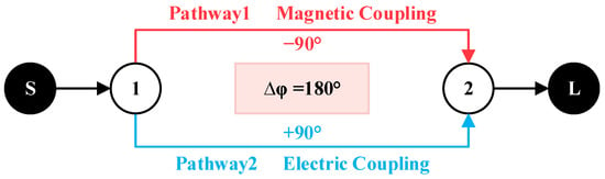
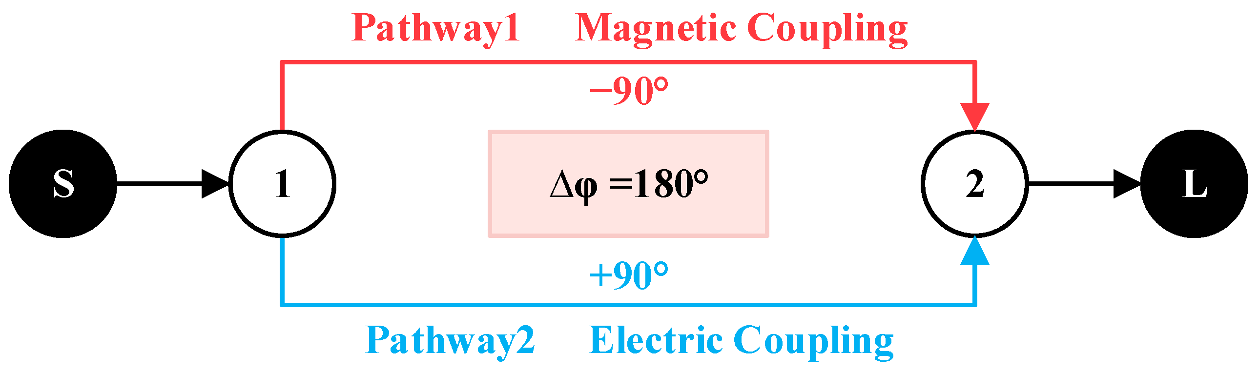
Figure 2 shows the topology of mixed electric and magnetic couplings. The numbers 1 and 2 denote the two resonators, while S and L represent the source and load, respectively. Two coupling pathways exist between Resonator 1 and Resonator 2. Pathway 1 is based on magnetic coupling and introduces a phase shift of −90°, while Pathway 2 is based on electric coupling and introduces a phase shift of +90°. This difference results in a total phase difference of 180° between the two pathways. The out-of-phase relationship leads to the destructive interference of radiation fields from the two coupling paths, generating a radiation null. For a three-slot configuration, at least two radiation nulls can be generated, and the antenna may achieve filtering performance. The detailed filtering mechanism is discussed in Section 3.4.
Figure 2.
Topology of mixed electric and magnetic couplings.
3. Antenna Design
3.1. Antenna Configuration
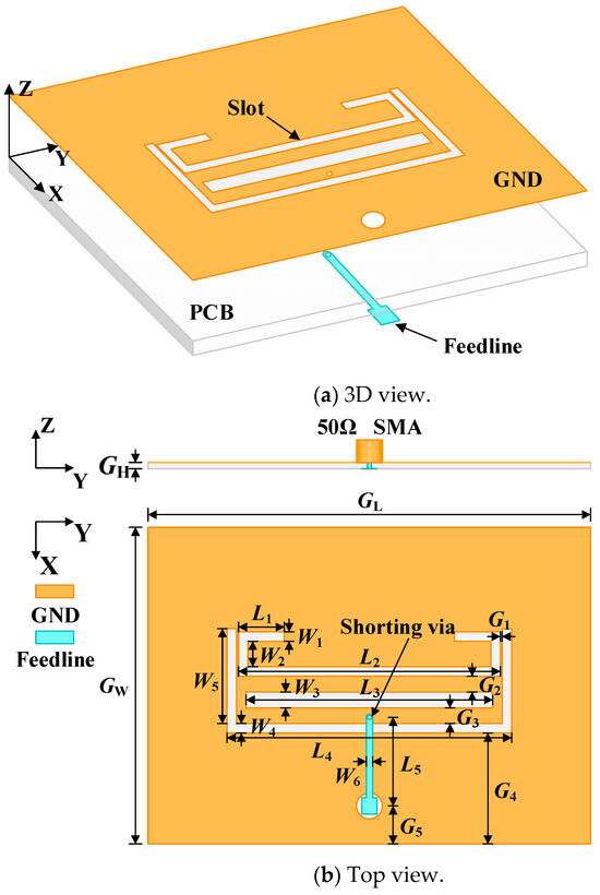
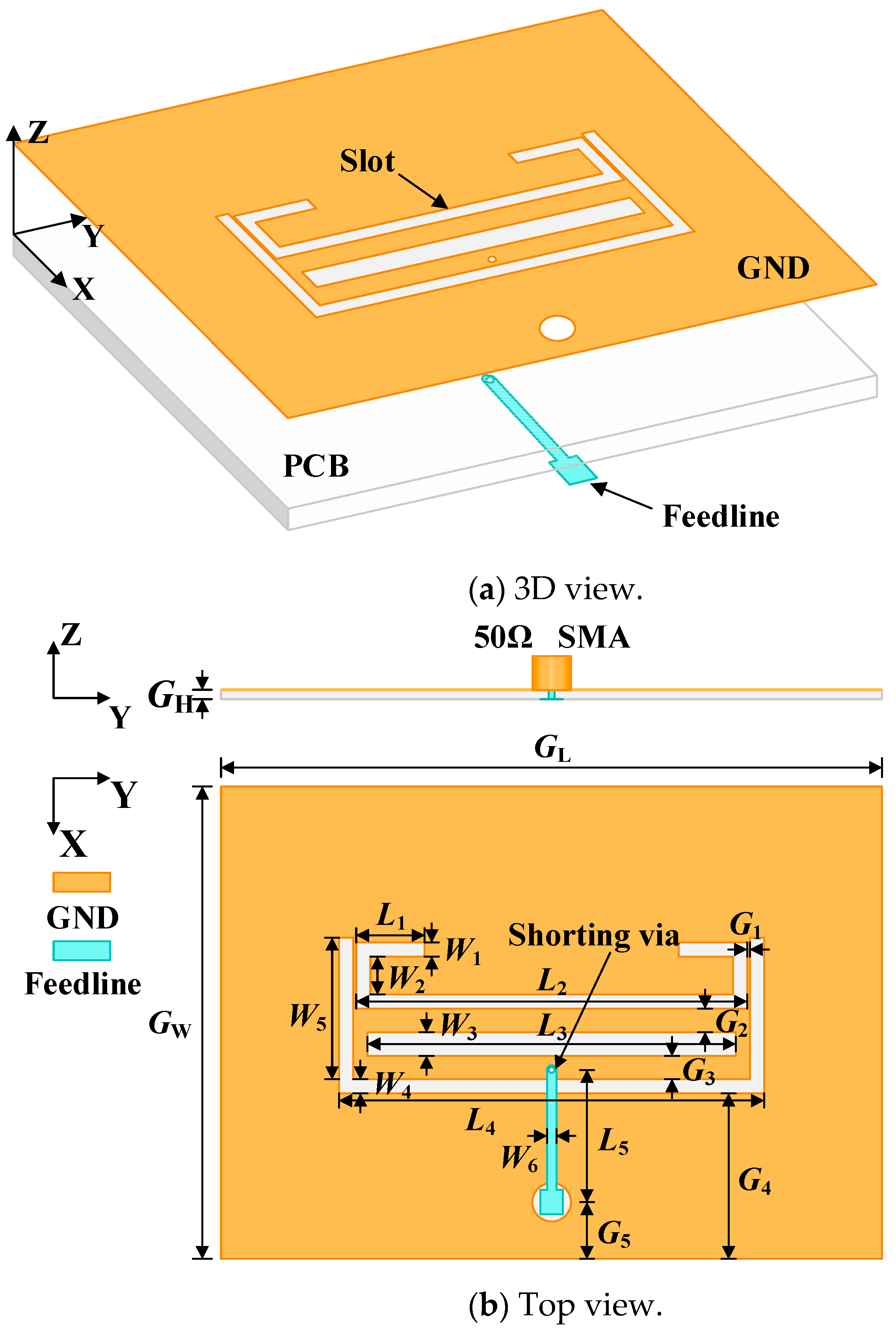
Figure 3 presents the configuration of the proposed three-slot filtering antenna. Its parameters are summarized in Table 1. The dielectric substrate has a relative permittivity of 3.2 and a thickness of 1 mm. A U-shaped slot, a folded slot, and a linear slot are etched into the ground. The three slots are placed in close proximity, with both electric coupling and magnetic coupling existing between the slots. Additionally, a shorting via is introduced at the terminal of the microstrip feedline. To excite the antenna, a 50 Ω SMA connector is employed.
Figure 3.
Configuration of the proposed three-slot filtering antenna. (a) 3D view. (b) Top view.
Table 1.
Parameters of the proposed three-slot filtering antenna.
3.2. Antenna Design Procedure
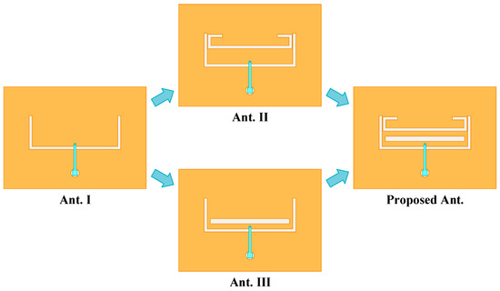
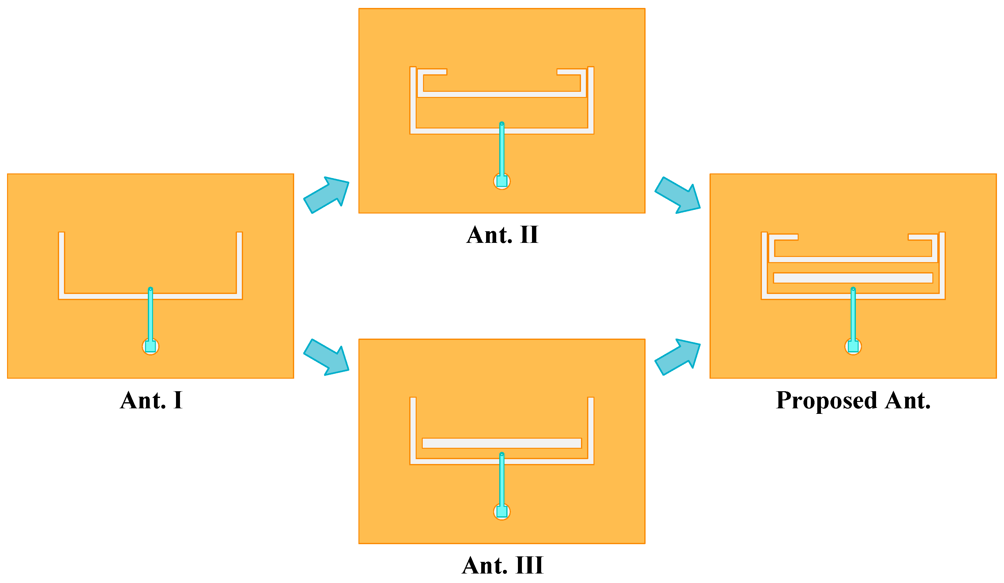
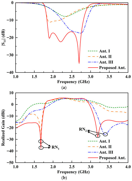
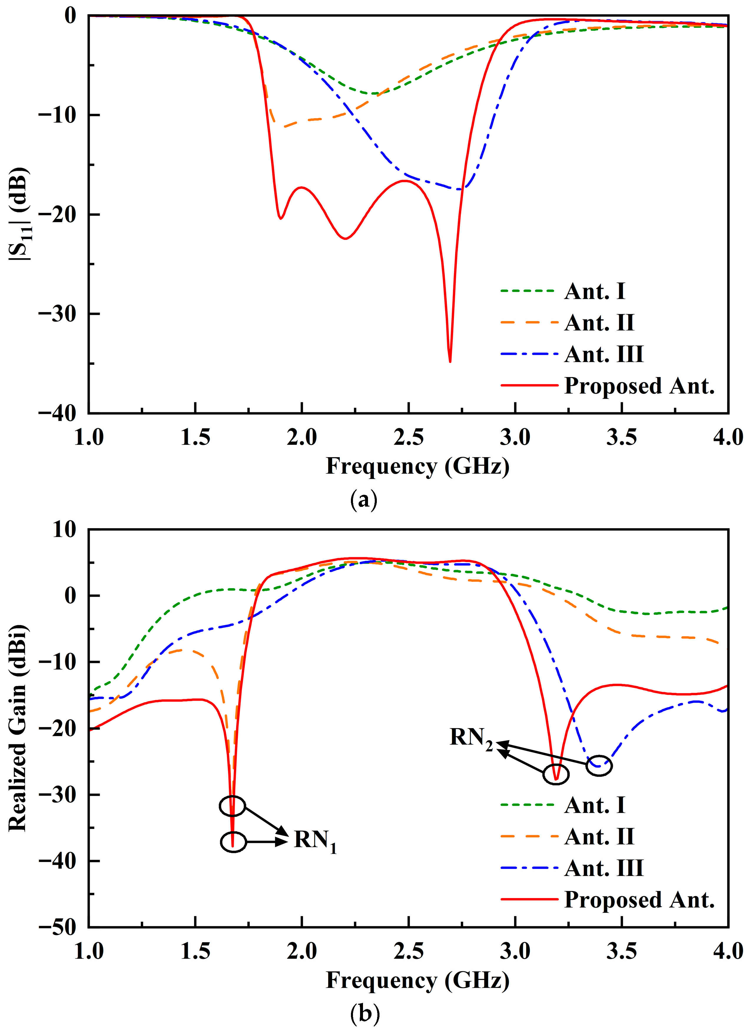
Figure 4 illustrates the evolutionary steps of the proposed three-slot filtering antenna. Figure 5 shows the |S11| and realized gain of the antennas. A U-shaped slot antenna serves as the initial design, denoted as Ant. I. The resonant frequency of the U-shaped slot antenna is 2.33 GHz, as shown in Figure 5a. A shorting via is introduced into the design to reduce the impedance of the feedline. With this low-impedance source feedline, the slot is excited in its full-wavelength resonant mode rather than the conventional half-wavelength mode [22].
Figure 4.
Evolutionary steps of the proposed three-slot filtering antenna.
Figure 5.
Performance of the reference antennas and the proposed three-slot filtering antenna. (a) |S11|. (b) Realized gain.
Ant. II is developed by integrating a folded slot into Ant. I. The two ends of the folded slot are close to those of the U-shaped slot. As shown in Figure 5a, this integration introduces a resonant frequency at 1.91 GHz, which is mainly attributed to the folded slot. This additional resonant frequency broadens the operating bandwidth. In Figure 5b, a low-frequency radiation null (RN1) occurs at 1.67 GHz, leading to enhanced frequency selectivity.
Ant. III is designed by introducing a linear slot into Ant. I. The linear slot is parallel to and in close proximity to the U-shaped slot. As shown in Figure 5a, a resonant frequency of 2.73 GHz is excited by the linear slot. In Figure 5b, a high-frequency radiation null (RN2) is produced at 3.40 GHz. This radiation null effectively enhances the selectivity.
Proposed Ant. is designed by combining the structural features of Ant. II and Ant. III. As shown in Figure 5a, this integrated design exhibits three distinct resonant frequencies, which contribute to achieving wideband operation. In Figure 5b, two radiation nulls are generated at 1.68 GHz and 3.19 GHz, respectively. With these two radiation nulls, the proposed three-slot filtering antenna achieves excellent filtering performance.
3.3. Electric Field Distribution and Radiation Mechanism
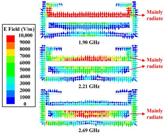
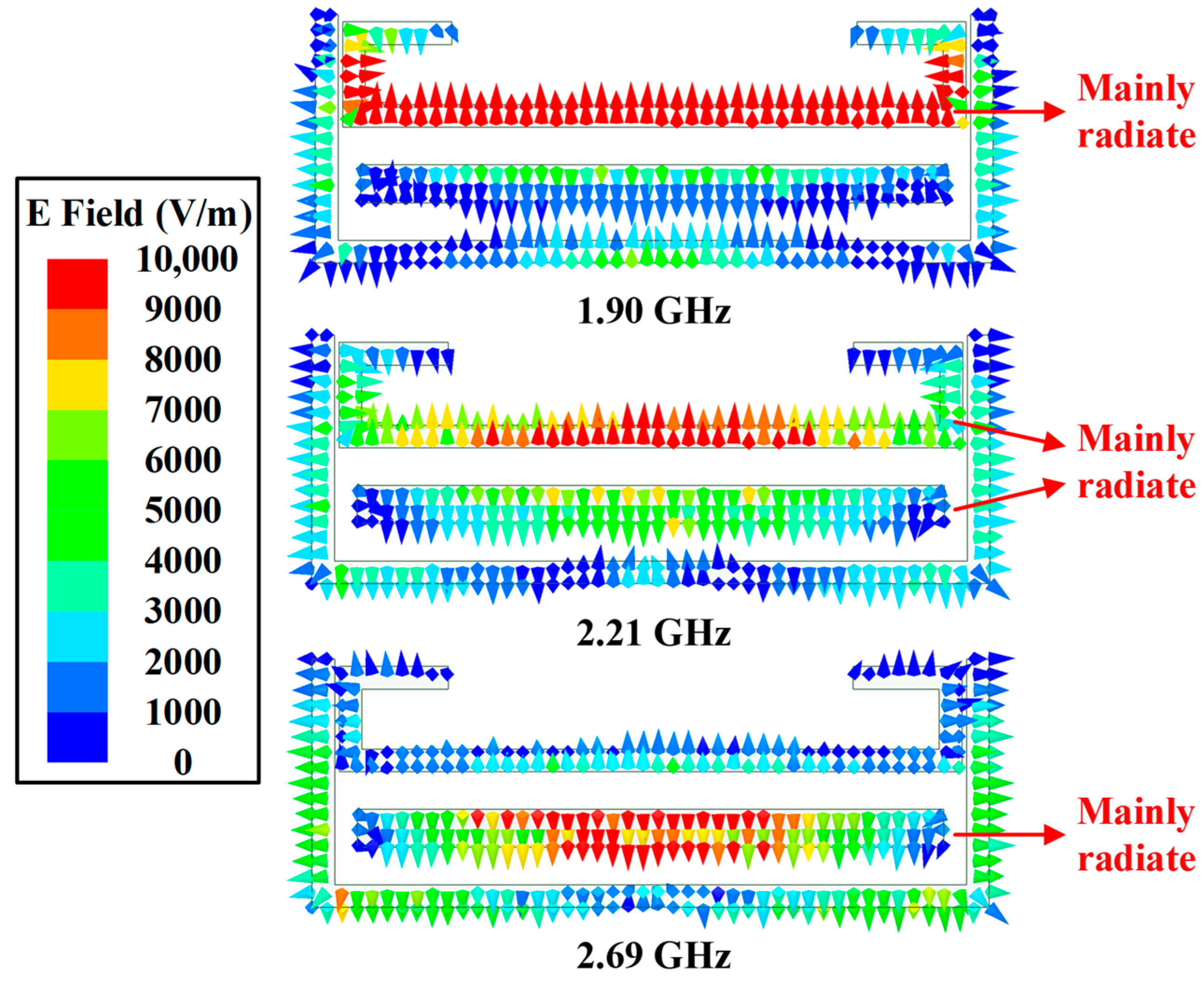
Figure 6 shows the electric field distributions of the proposed three-slot filtering antenna at 1.90 GHz, 2.21 GHz, and 2.69 GHz. At 1.90 GHz, the folded slot serves as the dominant radiating element, with the strongest electric field intensity. At 2.21 GHz, both the folded slot and the linear slot radiate simultaneously, indicating their joint contribution at the center frequency. At 2.69 GHz, the linear slot serves as the dominant radiating element, with the electric field mainly concentrated around it.
Figure 6.
Electric field distributions of the proposed three-slot filtering antenna at 1.90 GHz, 2.21 GHz, 2.69 GHz.
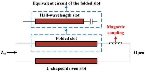
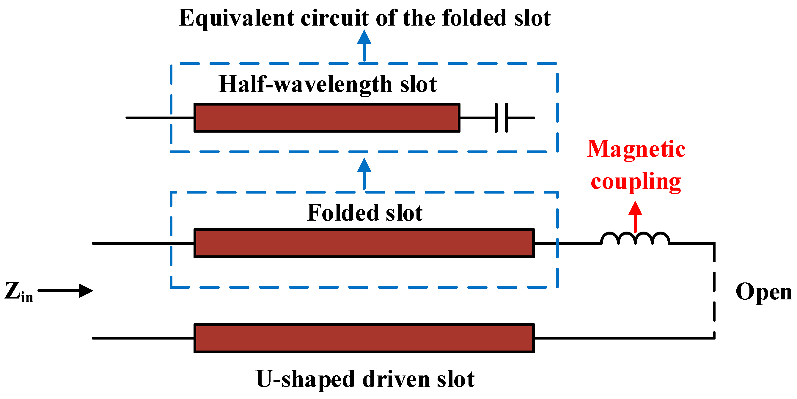
To analyze the radiation behavior of the folded slot at 1.90 GHz, we first calculate the theoretical half-wavelength at this frequency. At 1.90 GHz, the corresponding half-wavelength is given by the formula: . The folded slot has a physical length of 63.9 mm, which is longer than the calculated half-wavelength at 1.90 GHz. The coupling between the folded slot and the U-shaped driven slot affects its effective electrical length. Figure 7 depicts the equivalent circuit of the folded slot and the U-shaped driven slot at 1.90 GHz. According to transmission line theory, when a transmission line is open-circuited at the terminal and its length is less than a quarter-wavelength, it exhibits capacitive reactance. For the folded slot, its length is between 0.5 and 0.75, with the portion exceeding the half-wavelength being less than a quarter-wavelength. This excess length exhibits a capacitive behavior. Thus, the folded slot can be equivalent to a half-wavelength slot in series with a capacitor. Between the folded slot and the U-shaped driven slot, magnetic coupling exists. Magnetic coupling can be equivalent to a series inductor. The inductor and the capacitor can produce a series resonance, which reduces the effective electrical length to a half-wavelength. This allows the folded slot to resonate at 1.90 GHz despite its longer physical length.
Figure 7.
Equivalent circuit of the folded slot and the U-shaped driven slot at 1.90 GHz.
3.4. Filtering Property
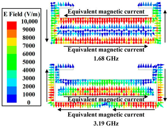
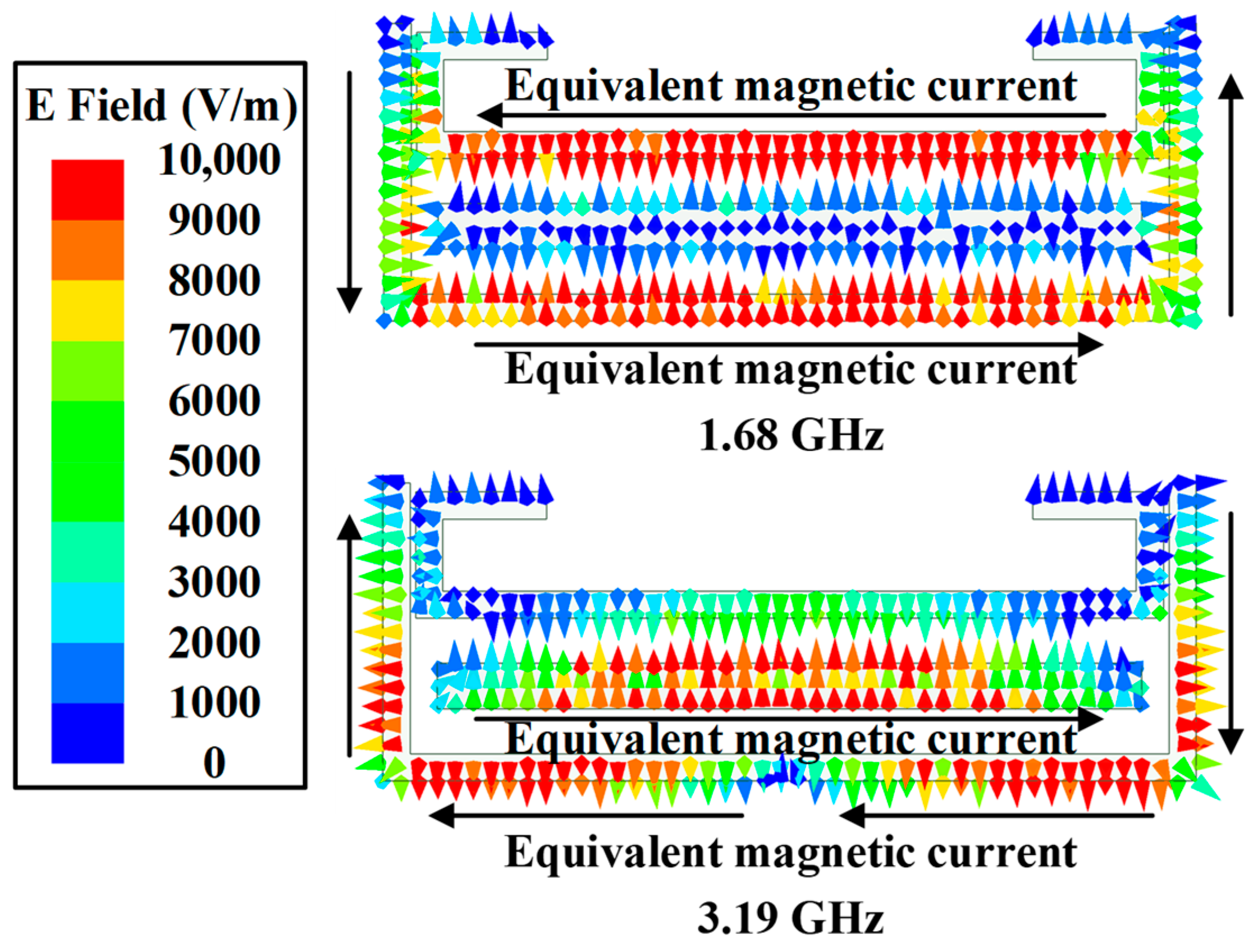
Figure 8 depicts the electric field distributions and equivalent magnetic currents of the proposed three-slot filtering antenna at the two radiation nulls. At 1.68 GHz, the horizontal segments of the U-shaped slot and the folded slot exhibit equal magnitude and opposite electric field directions, leading to out-of-phase equivalent magnetic currents. The radiation fields from the horizontal segments of the U-shaped slot and the folded slot undergo destructive interference. Meanwhile, the equivalent magnetic currents on the two vertical segments of the U-shaped slot are equal in magnitude and out of phase. Their radiation fields also undergo destructive interference. Thus, the low-frequency radiation null is produced. Similarly, at 3.19 GHz, the equivalent magnetic currents on the horizontal segments of the U-shaped slot and the linear slot are equal in magnitude and opposite in phase. The equivalent magnetic currents on the two vertical segments of the U-shaped slot are equal in magnitude and out of phase. Their respective radiation fields undergo destructive interference. Thus, the high-frequency radiation null is produced. These two radiation nulls endow the proposed three-slot antenna with excellent filtering performance.
Figure 8.
Electric field distributions of the proposed three-slot filtering antenna at 1.68 GHz, 3.19 GHz.
3.5. Parameter Discussion
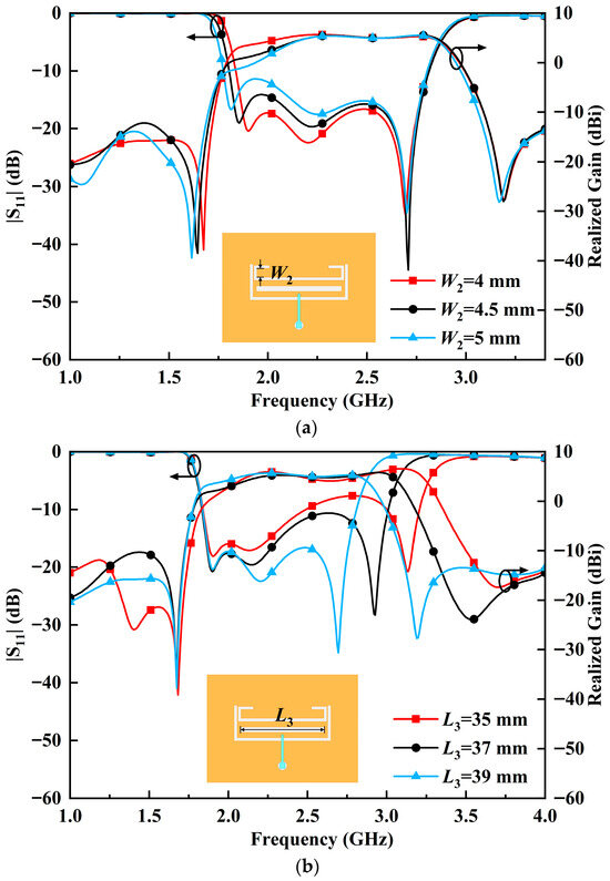
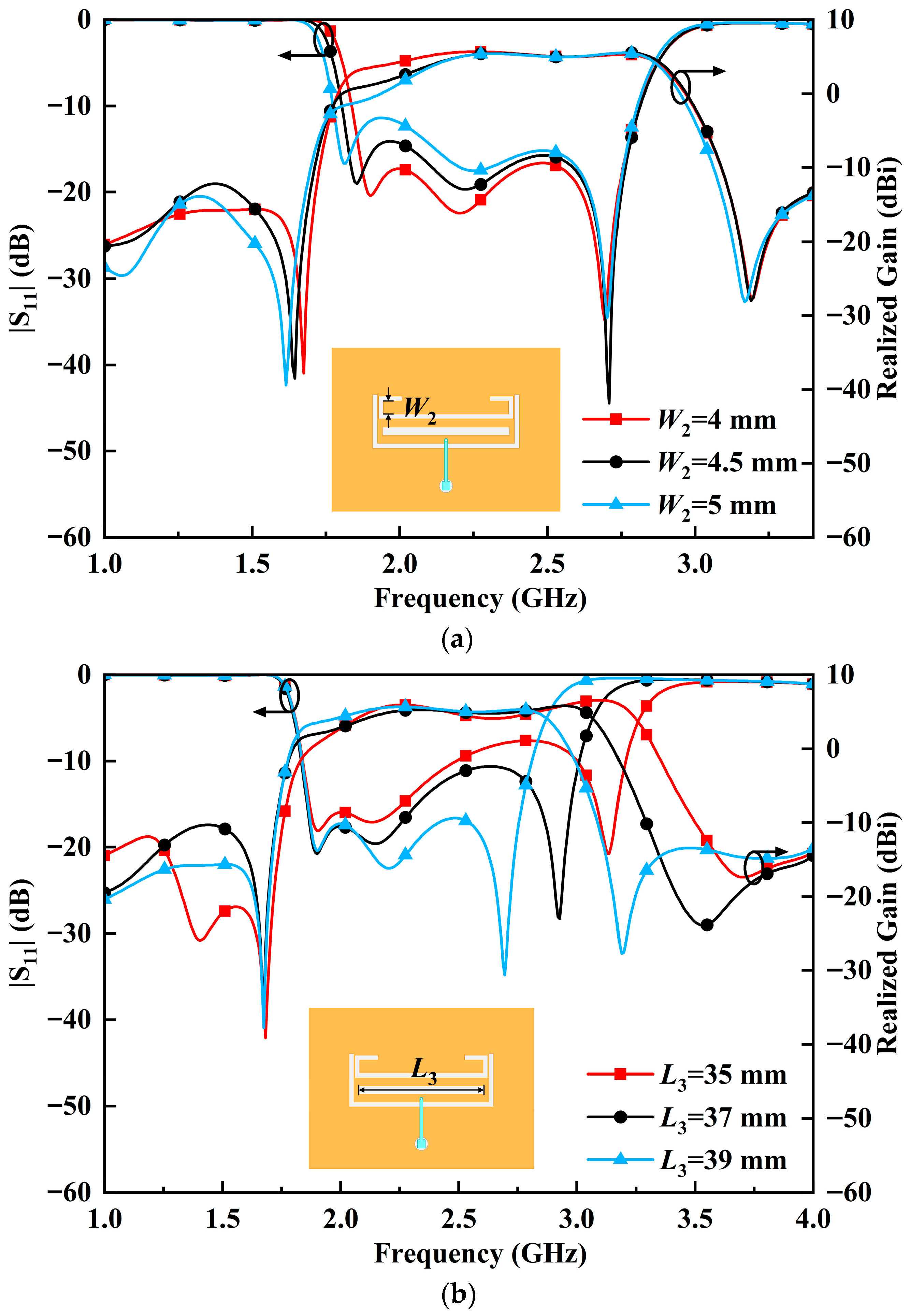
To validate the three-slot filtering antenna design, the parameters W2 and L3 are discussed and analyzed in Figure 9. As W2 decreases from 5 mm to 4 mm, the lowest resonant frequency and the low-frequency radiation null shift toward higher frequencies, while the center resonant frequency shifts to lower frequencies. The realized gain in the low-frequency sideband increases, improving the stability of the in-band gain. The out-of-band suppression in the low-frequency sideband changes from −16.1 dB to −18.4 dB, indicating an enhanced out-of-band suppression level. The low-frequency radiation null can be adjusted almost independently by the folded slot. When L3 increases from 35 mm to 39 mm, the highest resonant frequency shifts downward, varying from 3.13 GHz to 2.70 GHz. The center resonant frequency shifts toward the higher frequency band. The high-frequency radiation null shifts downward, varying from 3.70 GHz to 3.19 GHz. The low-frequency radiation null remains unchanged. The high-frequency radiation null can be independently adjusted by the linear slot. In addition to being affected by the U-shaped slot, the center resonant frequency is also influenced by the folded slot and the linear slot. The center resonant frequency is determined by the combined effect of the three slots.
Figure 9.
Performance of the proposed three-slot filtering antenna with varied parameters. (a) W2. (b) L3.
4. Antenna Measurement and Comparison
4.1. Antenna Measurement
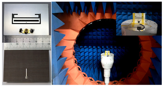
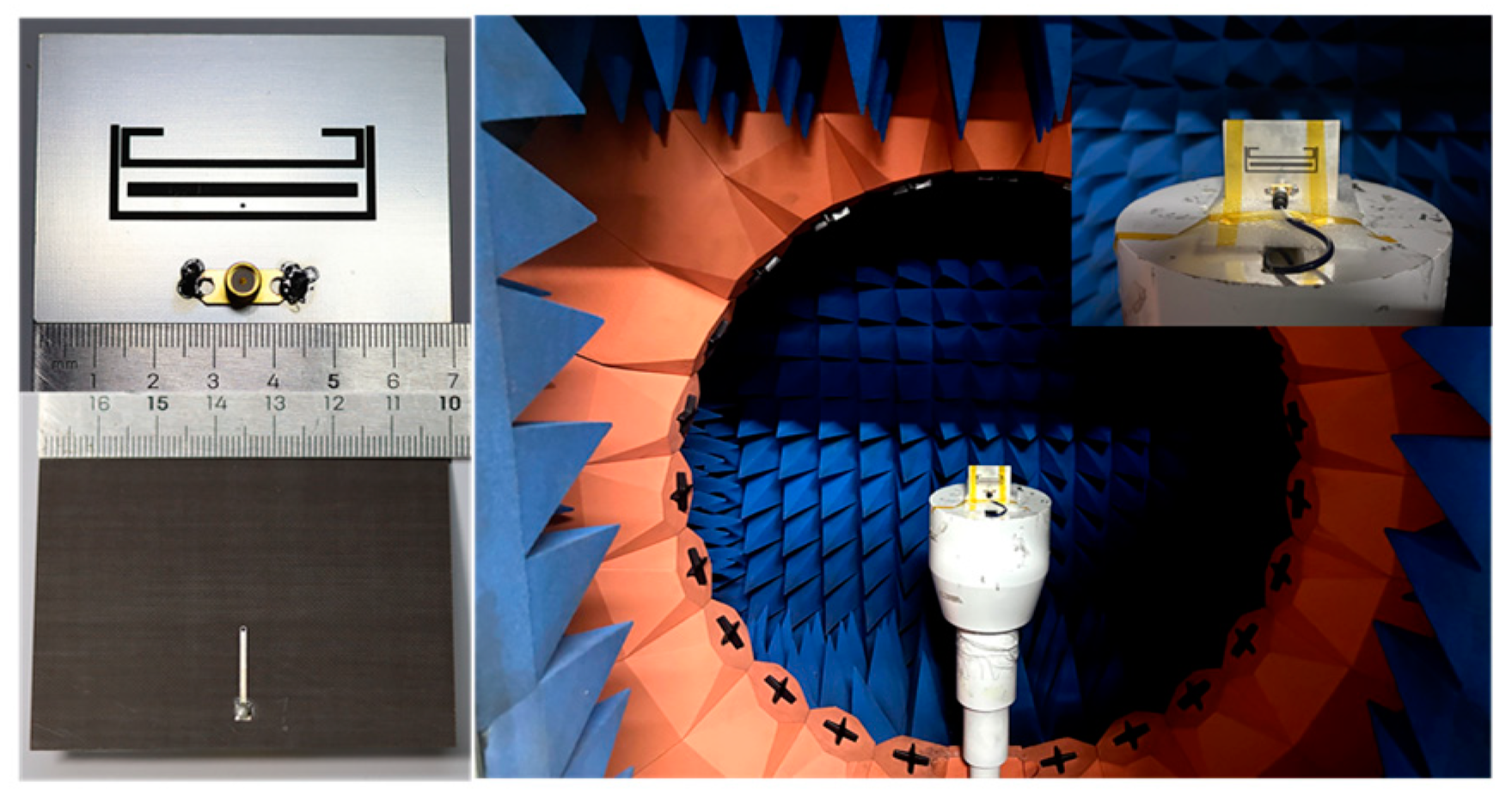
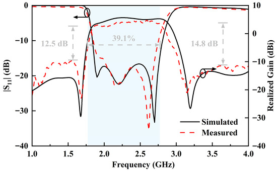
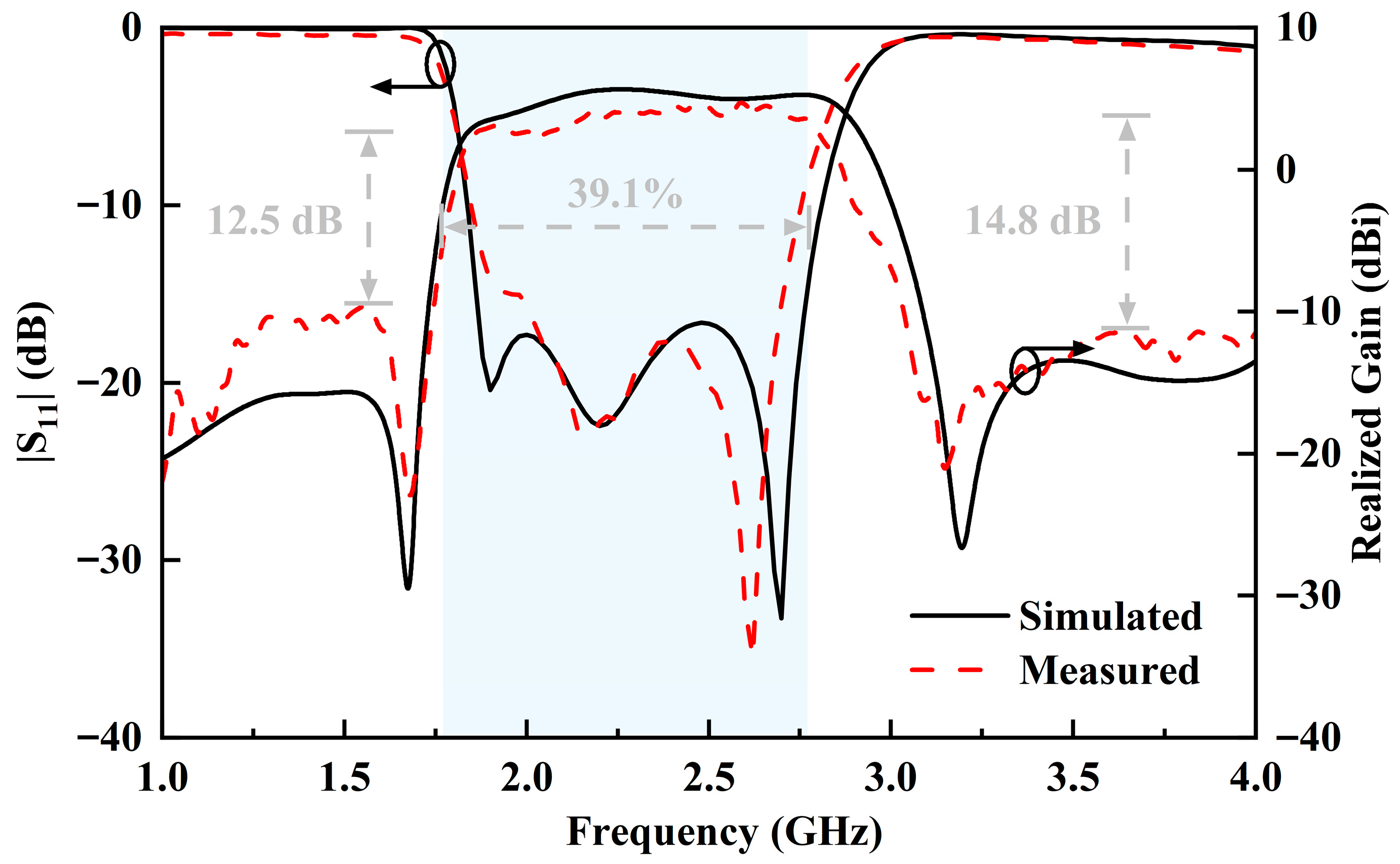
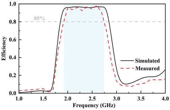
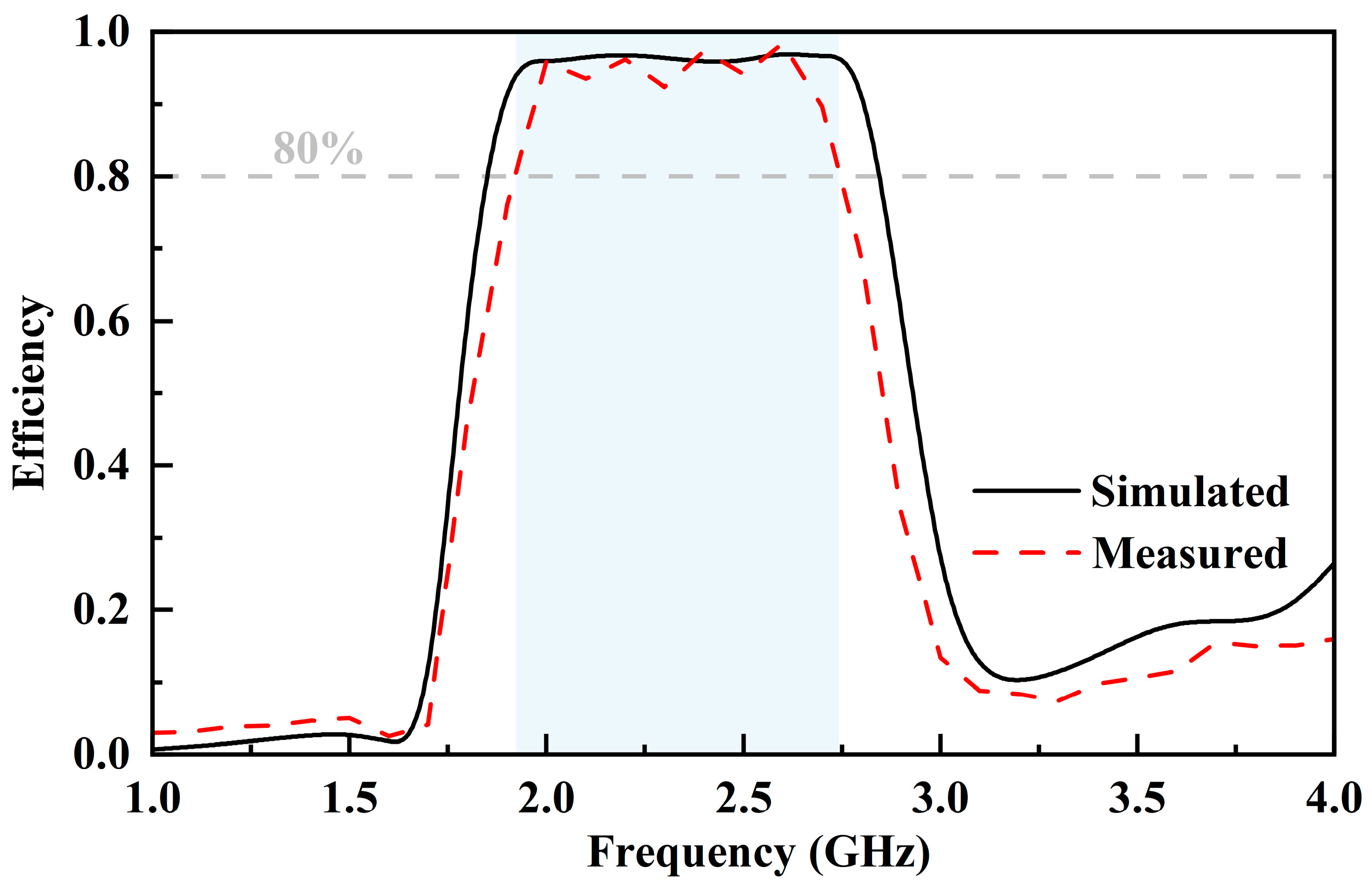
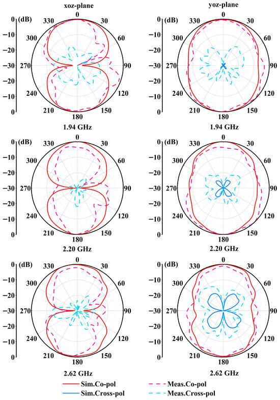
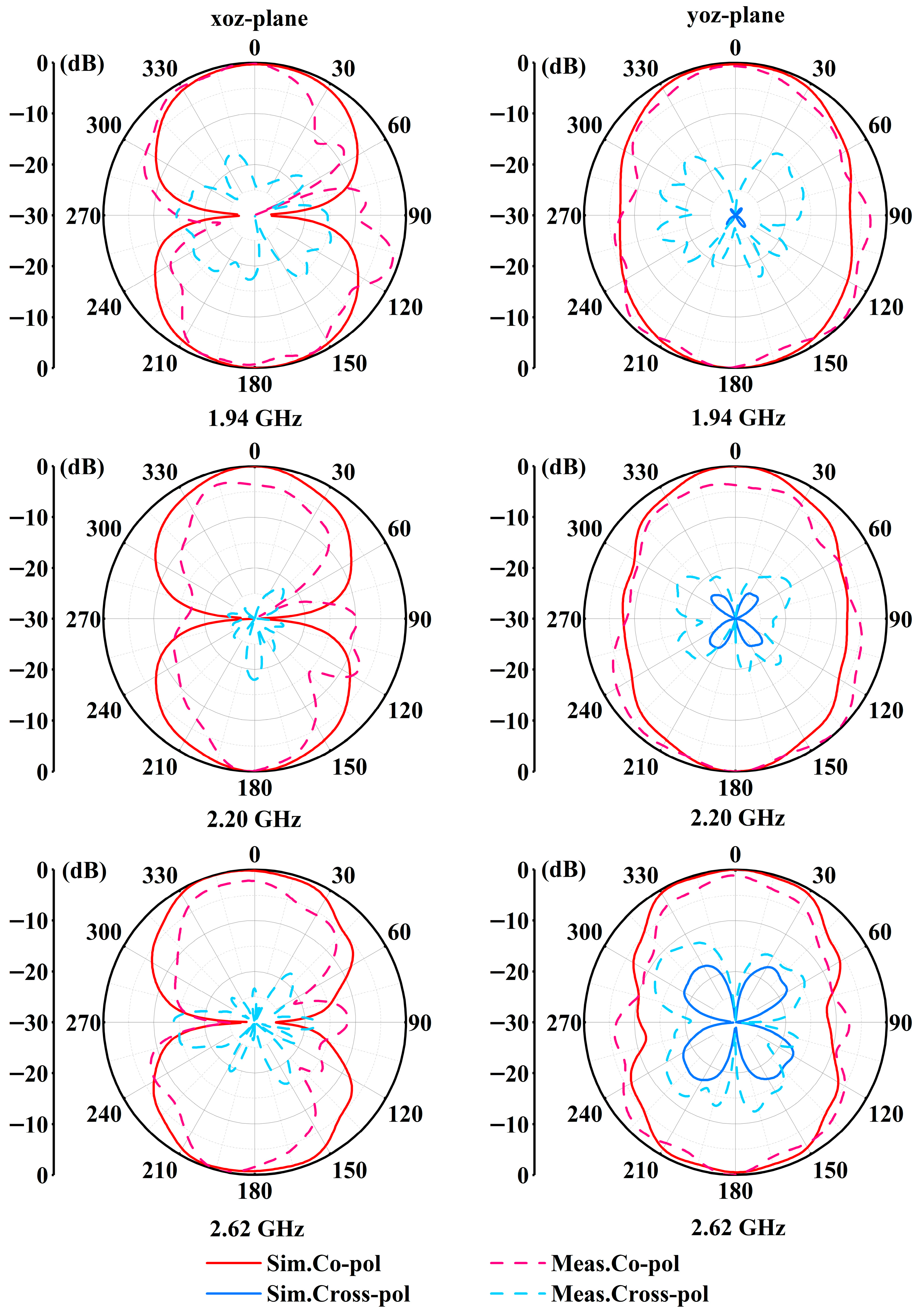
The proposed three-slot filtering antenna was fabricated and measured. Figure 10 depicts the prototype. |S11| was measured by a vector network analyzer. The realized gain and radiation patterns were measured in an anechoic chamber to characterize the antenna’s performance. In Figure 11, the measured results indicate that 10 dB impedance bandwidth ranges from 1.85 GHz to 2.75 GHz, with a relative impedance bandwidth of 39.1%. In the operating passband, the measured realized gain varies from 2.32 dBi to 4.85 dBi, with an average gain of 3.68 dBi. The gain variation within the passband is approximately 2.53 dB, indicating stable radiation performance across the wide operating bandwidth. Two radiation nulls are observed at 1.68 GHz and 3.14 GHz, respectively. Owing to these two radiation nulls, the out-of-band realized gain achieves a rapid roll-off. They also result in out-of-band suppression levels of 12.5 dB and 14.8 dB in the lower and upper sidebands, respectively. In Figure 12, the measured efficiency of the proposed three-slot filtering antenna exceeds 80% from 1.90 GHz to 2.70 GHz. In Figure 13, the radiation patterns of the proposed three-slot filtering antenna at 1.94 GHz, 2.20 GHz, and 2.62 GHz are plotted. The antenna maintains a bidirectional radiation pattern. The measured cross-polarization levels are below −15 dB in the xoz-plane and below −10 dB in the yoz-plane. The simulated cross-polarization levels are below −30 dB in the xoz-plane; thus, corresponding data are not presented in Figure 13.
Figure 10.
The prototype and the measurement setup.
Figure 11.
Measured and simulated |S11| and realized gain of the proposed three-slot filtering antenna.
Figure 12.
Measured and simulated efficiency of the proposed three-slot filtering antenna.
Figure 13.
Radiation patterns of the proposed three-slot filtering antenna.
4.2. Comparison and Discussion
To verify the advantages of the proposed three-slot filtering antenna, a comparison between our design and other reported antennas is listed in Table 2. In [3,5,19], additional circuits are employed, introducing extra loss and increasing the antenna volume. The designs in [9,12,13,14] achieve compact configurations and filtering performance without additional filters. However, their bandwidths are relatively narrow. Compared with previously reported slot filtering antennas, the proposed three-slot filtering antenna achieves a significantly wider impedance bandwidth of 39.1%. This improvement is mainly attributed to the excitation of three resonant frequencies within the passband, enabled by the introduction of two additional resonant slots. The mixed electric and magnetic couplings between these slots not only generate three resonances but also contribute to the generation of radiation nulls, thus achieving filtering performance while broadening the bandwidth. In contrast, conventional slot filtering antennas typically rely on only one or two resonant modes, resulting in narrower bandwidths. The proposed three-slot filtering antenna exhibits the advantages of wide bandwidth, compact size, good filtering performance, low profile, and easy fabrication.
Table 2.
Comparison between our design and other reported antennas.
5. Conclusions
In this article, a compact wideband three-slot filtering antenna based on mixed electric and magnetic couplings is proposed. By introducing two resonant slots, three resonant frequencies are excited, which effectively broadens the operating bandwidth. The electric and magnetic couplings between these slots lead to out-of-phase equivalent magnetic currents of the main radiating slots, thereby generating two radiation nulls. These two radiation nulls appear in the lower and upper bands, respectively, endowing the proposed antenna with high out-of-band suppression and good frequency selectivity. The measured results verify the design and demonstrate its advantages of wide bandwidth, compact size, and excellent filtering performance. The proposed three-slot filtering antenna exhibits promising potential for applications in modern wireless communication systems.
Author Contributions
Conceptualization, X.L.; Methodology, K.-L.W.; Investigation, K.-L.W.; Writing—original draft, K.-L.W.; Writing—review & editing, D.-S.L.; Supervision, D.-S.L.; Project administration, X.L. All authors have read and agreed to the published version of the manuscript.
Funding
This research received no external funding.
Data Availability Statement
The original contributions presented in this study are included in the article. Further inquiries can be directed to the corresponding author.
Conflicts of Interest
The authors declare no conflicts of interest.
References
- Zuo, J.; Chen, X.; Han, G.; Li, L.; Zhang, W. An integrated approach to RF antenna-filter co-design. IEEE Antennas Wirel. Propag. Lett. 2009, 8, 141–144. [Google Scholar] [CrossRef] [Scilit]
- Sun, G.-H.; Wong, S.-W.; Zhu, L.; Chu, Q.-X. A compact printed filtering antenna with good suppression of upper harmonic band. IEEE Antennas Wirel. Propag. Lett. 2015, 15, 1349–1352. [Google Scholar] [CrossRef] [Scilit]
- Tang, M.-C.; Wen, Z.; Wang, H.; Li, M.; Ziolkowski, R.W. Compact, frequency-reconfigurable filtenna with sharply defined wideband and continuously tunable narrowband states. IEEE Trans. Antennas Propag. 2017, 65, 5026–5034. [Google Scholar] [CrossRef] [Scilit]
- Emadeddin, A.; Jonsson, B.L.G. A fully integrated filtering Vivaldi antenna with high selectivity and wide out-of-band suppression. IEEE Access 2024, 12, 2690–2700. [Google Scholar] [CrossRef] [Scilit]
- Hu, K.-Z.; Tang, M.-C.; Wang, Y.; Li, D.; Li, M. Compact, vertically integrated duplex filtenna with common feeding and radiating SIW cavities. IEEE Trans. Antennas Propag. 2020, 69, 502–507. [Google Scholar] [CrossRef] [Scilit]
- Zhang, Y.-M.; Zhang, S. Two-port dual-band filtering network and its application on filtering antennas. IEEE Antennas Wirel. Propag. Lett. 2022, 22, 679–683. [Google Scholar] [CrossRef] [Scilit]
- Huang, T.; Liu, H.; Xu, H.; Geng, L. Three-dimensional printed mm-wave circularly polarized filtering antenna with flexible design and spurious suppression. IEEE Trans. Antennas Propag. 2023, 71, 8266–8271. [Google Scholar] [CrossRef] [Scilit]
- Li, Y.C.; Chu, K.L.; Zhang, T.; Xue, Q. A scalable filtering MIMO antenna with space diversity based on shared SIW cavities. IEEE Antennas Wirel. Propag. Lett. 2025, 24, 1769–1773. [Google Scholar] [CrossRef] [Scilit]
- Liang, G.-Z.; Chen, F.-C.; Yuan, H.; Xiang, K.-R.; Chu, Q.-X. A high selectivity and high efficiency filtering antenna with controllable radiation nulls based on stacked patches. IEEE Trans. Antennas Propag. 2021, 70, 708–713. [Google Scholar] [CrossRef] [Scilit]
- Tian, M.; Yan, N.; Luo, Y.; Ma, K. A low-cost high-gain filtering patch antenna using SISL technology for 5G application. IEEE Antennas Wirel. Propag. Lett. 2021, 20, 2270–2274. [Google Scholar] [CrossRef] [Scilit]
- Chen, B.-J.; Yang, X.-S.; Wang, B.-Z. A compact high-selectivity wideband filtering antenna with multipath coupling structure. IEEE Antennas Wirel. Propag. Lett. 2022, 21, 1654–1658. [Google Scholar] [CrossRef] [Scilit]
- Yin, J.-Y.; Bai, T.-L.; Deng, J.-Y.; Ren, J.; Sun, D.; Zhang, Y.; Guo, L.-X. Wideband single-layer substrate integrated waveguide filtering antenna with U-shaped slots. IEEE Antennas Wirel. Propag. Lett. 2021, 20, 1726–1730. [Google Scholar] [CrossRef] [Scilit]
- Liu, Q.; Zhu, L. A compact wideband filtering antenna on slots-loaded square patch radiator under triple resonant modes. IEEE Trans. Antennas Propag. 2022, 70, 9882–9887. [Google Scholar] [CrossRef] [Scilit]
- Zhong, H.-N.; Li, J.-F.; Ye, L.-H.; Tian, X.-X.; Hu, Z.-X.; Zhang, G. A Patch Antenna With Omnidirectional and Excellent Radiation Suppression in Stop-Bands. IEEE Antennas Wirel. Propag. Lett. 2025, 24, 2657–2661. [Google Scholar] [CrossRef] [Scilit]
- Yang, M.; Wu, B.; Fan, C.; Xie, H.-Y.; Chen, J.-Z.; Wu, L. Synthesis and design of filtering antenna with flexible passband and radiation null based on parallel scheme. IEEE Antennas Wirel. Propag. Lett. 2021, 20, 838–842. [Google Scholar] [CrossRef] [Scilit]
- He, W.; Li, J.; Wu, S.; Yan, S.; Xu, K.-D. 3D printed millimeter-wave magnetoelectric dipole antenna array fed by filtering butler matrix. AEU-Int. J. Electron. Commun. 2025, 191, 155664. [Google Scholar] [CrossRef] [Scilit]
- Yang, D.; Zhai, H.; Guo, C.; Li, H. A compact single-layer wideband microstrip antenna with filtering performance. IEEE Antennas Wirel. Propag. Lett. 2020, 19, 801–805. [Google Scholar] [CrossRef] [Scilit]
- Yao, S.F.; Xu, S.; Xue, Y.M.; Yang, S.J.; Su, H.F.; Xue, Q.; Zhang, X.Y. Miniaturized dual-wideband millimeter-wave filtenna in package for 5G applications. IEEE Antennas Wirel. Propag. Lett. 2023, 22, 1726–1730. [Google Scholar] [CrossRef] [Scilit]
- Fakharian, M.M.; Rezaei, P.; Orouji, A.A.; Soltanpur, M. A wideband and reconfigurable filtering slot antenna. IEEE Antennas Wirel. Propag. Lett. 2016, 15, 1610–1613. [Google Scholar] [CrossRef] [Scilit]
- Xie, Y.; Chen, F.-C.; Qian, J.-F. Design of integrated duplexing and multi-band filtering slot antennas. IEEE Access 2020, 8, 126119–126126. [Google Scholar] [CrossRef] [Scilit]
- Liu, T.-T.; Li, J.-F.; Ye, L.-H.; Tian, X.-X.; Mao, C.-X. Low-Profile Duplex Filtering Antenna With High Isolation and High Roll-Off Filtering Response. IEEE Antennas Wirel. Propag. Lett. 2024, 23, 3907–3911. [Google Scholar] [CrossRef] [Scilit]
- Wang, H.; Zhou, D.; Xue, L.; Gao, S.; Xu, H. Modal analysis and excitation of wideband slot antennas. IET Microw. Antennas Propag. 2017, 11, 1887–1891. [Google Scholar] [CrossRef] [Scilit]

Disclaimer/Publisher’s Note: The statements, opinions and data contained in all publications are solely those of the individual author(s) and contributor(s) and not of MDPI and/or the editor(s). MDPI and/or the editor(s) disclaim responsibility for any injury to people or property resulting from any ideas, methods, instructions or products referred to in the content. |
© 2026 by the authors. Licensee MDPI, Basel, Switzerland. This article is an open access article distributed under the terms and conditions of the Creative Commons Attribution (CC BY) license.