


Abstract
There are some methods based on the railway power conditioner (RPC) that can address the imbalance issue, improve load fluctuation, and manage the regenerative braking energy (RBE) of the traction power supply system in high-speed railways. However, the coupling of imbalance compensation and energy storage is a problem in the RPC method. Therefore, a novel decoupling control method is proposed in this paper. The topology of the method is based on a three-phase converter, and the energy storage unit is connected to the DC side of the converter. A decoupling possibility and principle analysis is carried out. The mechanism of the proposed method in coping with different working conditions of high-speed railways is introduced in detail. Then, a capacity analysis and the control method are presented. According to the theoretical analysis, while the traditional RPC requires no extra capacity under single-task operations, its required capacity increases by 15.47% under typical hybrid conditions and can even surge by over 30% under severe coupling scenarios, to achieve the same effect as the proposed decoupled method. Finally, simulations and experiments are carried out to verify the effectiveness and flexibility of the novel method.
1. Introduction
In modern society, energy conservation and energy efficiency improvement are the main trends all over the world [1,2]. High-speed railways have become one of the main modes of travel and transportation, consuming large amounts of energy every year [3]. As a result, regenerative braking is used to save energy in high-speed railways. However, regenerative braking energy (RBE) has not been effectively utilized yet [4].
High-speed trains are highly fluctuating loads, which leads to a low usage rate of the traction transformer [5]. High-speed trains are also single-phase loads, which can generate a lot of negative-sequence currents (NSCs). NSCs will cause the imbalance issue of the three-phase power grid, which is the most serious power quality problem in high-speed railway power supply systems [6].
Currently, there are three main ways to deal with RBE: (i) the energy-consuming method, (ii) the energy feedback method, and (iii) the energy storage and reuse method [7,8,9,10]. In the energy-consuming method, the RBE is consumed by the resistance, which is a waste of energy. For the energy feedback method, if the whole RBE can be consumed by the trains at the same power supply arm, then this method would achieve effective results. However, in fact, only a small amount of RBE can be consumed by the trains at the same power supply in high-speed railways, while most of the RBE is fed back to the three-phase through the traction transformer. The feedback energy is not of good quality and may worsen the imbalance issue. Hence, some researchers have come up with a compromise solution to have the RBE fed back to the train station and consumed by the electrical equipment. However, the electrical equipment in the train station has relatively constant small power loads, which cannot consume the short-time high-power RBE well. The energy storage and reuse method can achieve a high energy utilization rate, which has attracted the attention of many researchers [11,12,13,14,15]. On-board and off-board energy storage methods have been studied. However, all of these studies focus on DC traction power supply systems, while high-speed railways use AC traction power supply systems that have higher voltage levels and generate larger RBE power. Ref. [16] takes the RBE in AC traction power supply systems into consideration, but the study simply regards RBE as a factor to consider in general energy management and planning. It is worth noting that [17] proposes a novel hybrid modulation scheme, which successfully resolves the issue of sudden efficiency drop and power fluctuation (ripple) in the wireless charging system during low-load operation. This research provides a solution for optimizing the energy efficiency of transportation electrification.
The imbalance issue is an important power quality problem of the railway. Trains running in high-speed railways have a higher power, which makes the imbalance issue more prominent [18,19,20,21]. Many methods have been proposed to solve the imbalance issue, such as advancing the voltage level of the power supply [22], applying a balancing traction transformer [23], and installing compensation equipment. Among these methods, the railway power conditioner (RPC), which was proposed by Japanese scholars in 1993, is the most effective imbalance compensation equipment [24]. Then, many scholars have conducted extensive work to optimize the topology of RPC [25,26,27,28] and study how to apply the RPC in the VV traction power supply system, which is the most widely used type of traction transformer. Refs. [29,30] introduced the modular multilevel converter (MMC) into the RPC topology. However, the traditional RPC can only deal with power quality problems in high-speed railways and is incapable of solving the problems of RBE and the low usage rates of the traction transformer. Ref. [31] proposed a supercapacitor-integrated RPC method which can compensate for imbalance and store RBE. However, the functions of imbalance compensation and energy storage of the RPC-based method are coupled. In order to minimize the peak power requirements of the traction transformer, the equipment must absorb energy from the three-phase power supply grid when the RBE is not enough. Under such circumstances, RPC will generate NSC when it absorbs active power from the power grid.
In this paper, a novel imbalance compensation method considering energy storage is proposed. The functions of imbalance compensation and energy storage are decoupled, and they will not affect each other. The topology of the method is based on a three-phase converter, and the energy storage unit is connected to the DC side of the converter. A decoupling possibility and principle analysis is carried out, and the application of the proposed method in different working conditions of high-speed railways is presented in Section 3. Then, a capacity analysis and the control method are presented in Section 4. According to the theoretical analysis, the RPC-based methods must increase capacity by 15.47% to achieve the same effect as the new method. Finally, simulations and experiments are carried out to verify the effectiveness and flexibility of the novel method.
2. Topology
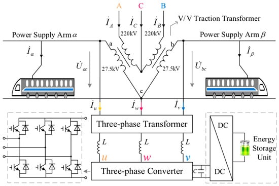
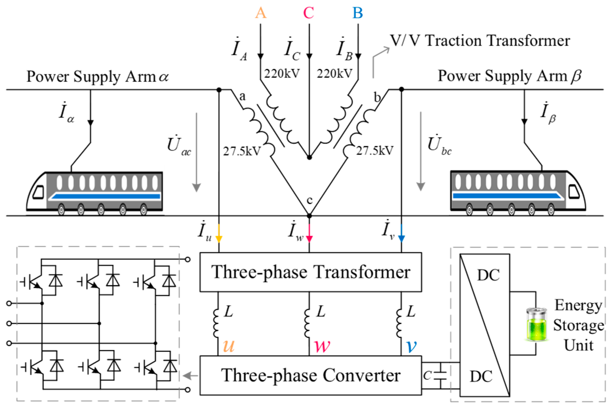
The topology of the novel method is shown in Figure 1. The high-speed railway traction power supply system consists of a V/V transformer and two power supply arms. The turn ratio of the V/V transformer is 220 kV: 27.5 kV. The three-phase converter is connected to the traction grid through a three-phase transformer with a turn ratio of 27.5 kV: 2 kV and consists of six IGBTs and diodes in anti-parallel. The capacitor at the DC side of the three-phase converter is connected to the energy storage unit. The energy storage medium is in a hybrid structure composed of a supercapacitor and battery, which has a suitable energy storage power and capacity for RBE in high-speed railways. and are the load currents of the two traction power supply arms, respectively. , , and are the three-phase currents of the power grid. , , and are the injecting or absorbing currents of the three-phase converter.
Figure 1.
Topology of the novel energy storage and imbalance compensation system.
3. Theoretical Analysis
3.1. Decoupling Possibility Analysis
If phase A voltage is the reference phasor, the voltages of power supply arms α and β are
Assuming that the transformer ratio is k, the high-speed train can be seen as a resistive load, and the three-phase current of the power supply system can be deducted:
According to the symmetrical component method, the negative- and positive-sequence components of the three-phase current can be obtained as follows:
Equation (3) shows that the load currents affect the NSC, and the currents absorbed or injected by RPC can be seen as load currents. Therefore, in the RPC-based energy storage method, the energy storage is coupled with the imbalance compensation.
Assuming that a three-phase system includes imbalance voltages and currents in the V/V traction power supply system, which has no zero-sequence voltage and current, the imbalance voltages should be as follows:
where is the positive-sequence voltage, which can be expressed as follows:
and is the negative-sequence voltage, which can be expressed as follows:
The imbalance current should be as follows:
where is the PSC, which can be expressed as follows:
and is the NSC, which can be expressed as follows:
Then, the instantaneous power matrix can be obtained as follows:
where p1 and p4 are the same sequence power, while p2 and p3 are different sequence powers. Bringing (2), (3), (5), and (6) into (7), the following equation can be obtained:
which shows that the active power of the traction power supply system only depends on voltage and current with the same sequence. As the three-phase voltage of the power grid only contains a small amount of negative-sequence voltage and remains basically unchanged, the energy storage of the traction power supply system only relates to the PSC, and the PSC and NSC do not influence each other. Therefore, the energy storage and the imbalance compensation of the high-speed railway can be decoupled.
3.2. Energy Storage and Imbalance Compensation Principle
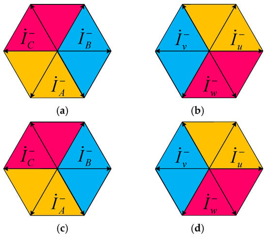
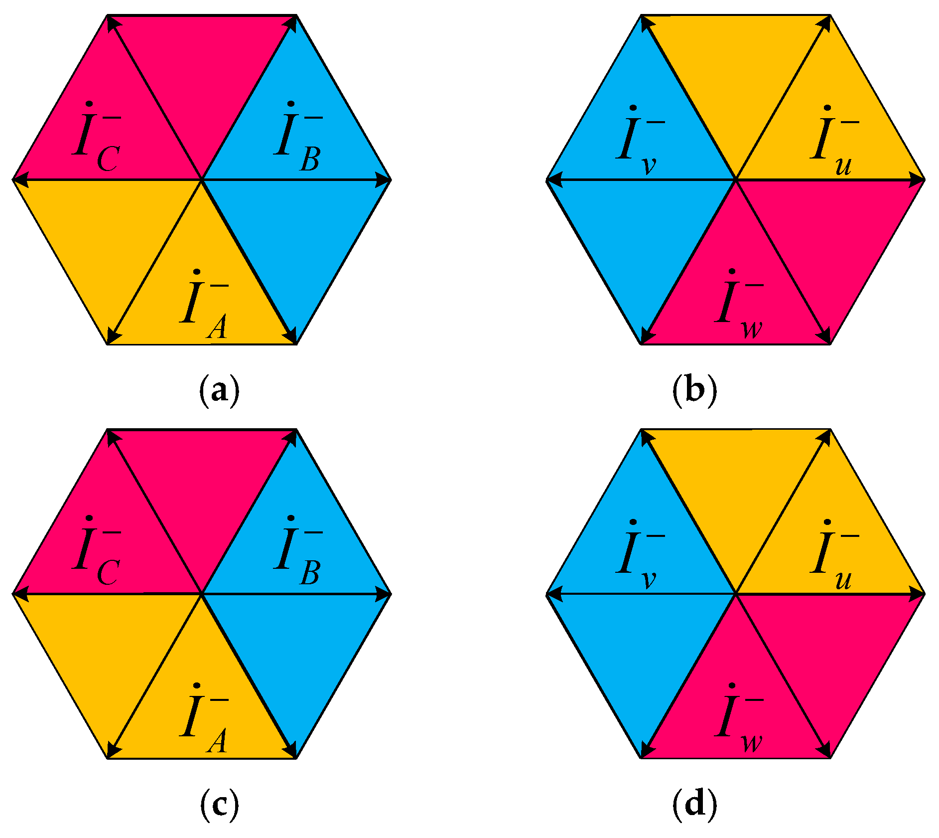
According to Figure 1, the energy storage can be implemented by injecting a three-phase current with the opposite phase of the PSC through the three-phase converter. Meanwhile, the imbalance compensation can be achieved by injecting a three-phase current with the opposite phase of the NSC also through the three-phase converter. From Equation (3), the expressions of the two three-phase currents can be derived:
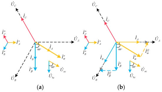
where is the imbalanced compensation current (UCC), and is the energy storage current (ESC) corresponding to phase A. Then, the whole phase diagrams of the two three-phase currents are shown in Figure 2.
Figure 2.
Phase diagrams of the energy storage and imbalance compensation principle. (a) NSC; (b) imbalance compensation current; (c) PSC; (d) energy storage current.
3.3. Working Conditions
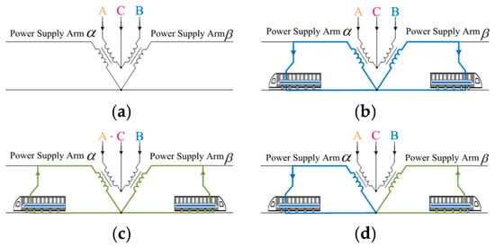
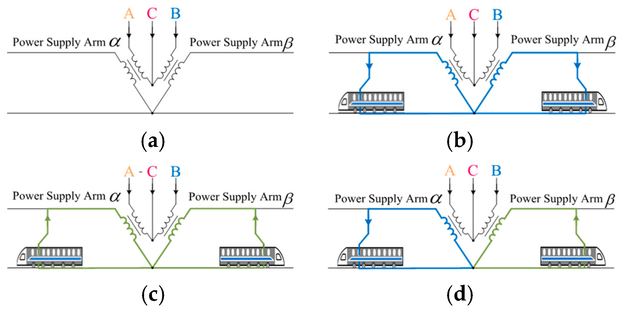
There are four different working conditions of the high-speed railway energy storage considering imbalance compensation, which are shown in Figure 3.
Figure 3.
Working conditions. (a) No-train-load condition; (b) pure traction condition; (c) pure regenerative braking condition; (d) hybrid condition.
Figure 3a shows the no-train-operating condition (Condition A): there are no trains working, and the converter absorbs the energy from the power grid. Figure 3b shows the pure traction condition (Condition B): all of the trains are working in traction mode. Figure 3c shows the pure regenerative braking condition (Condition C): all of the trains are working in regenerative braking mode. Figure 3d shows the hybrid condition (Condition D): trains on one power supply arm (α) are working in traction mode and trains on the other power supply arm (β) are working in regenerative braking mode.
The expressions of the UCCs and ESCs of the four working conditions are shown in Table 1, where ω is the ratio of the energy storage. The total current (phase-u) injected into the traction system by the converter should be as follows:
Table 1.
Expressions of the UCCs and ESCs of the four working conditions.
4. Capacity and Power Analysis
4.1. Capacity Requirement and Power Flow Analysis
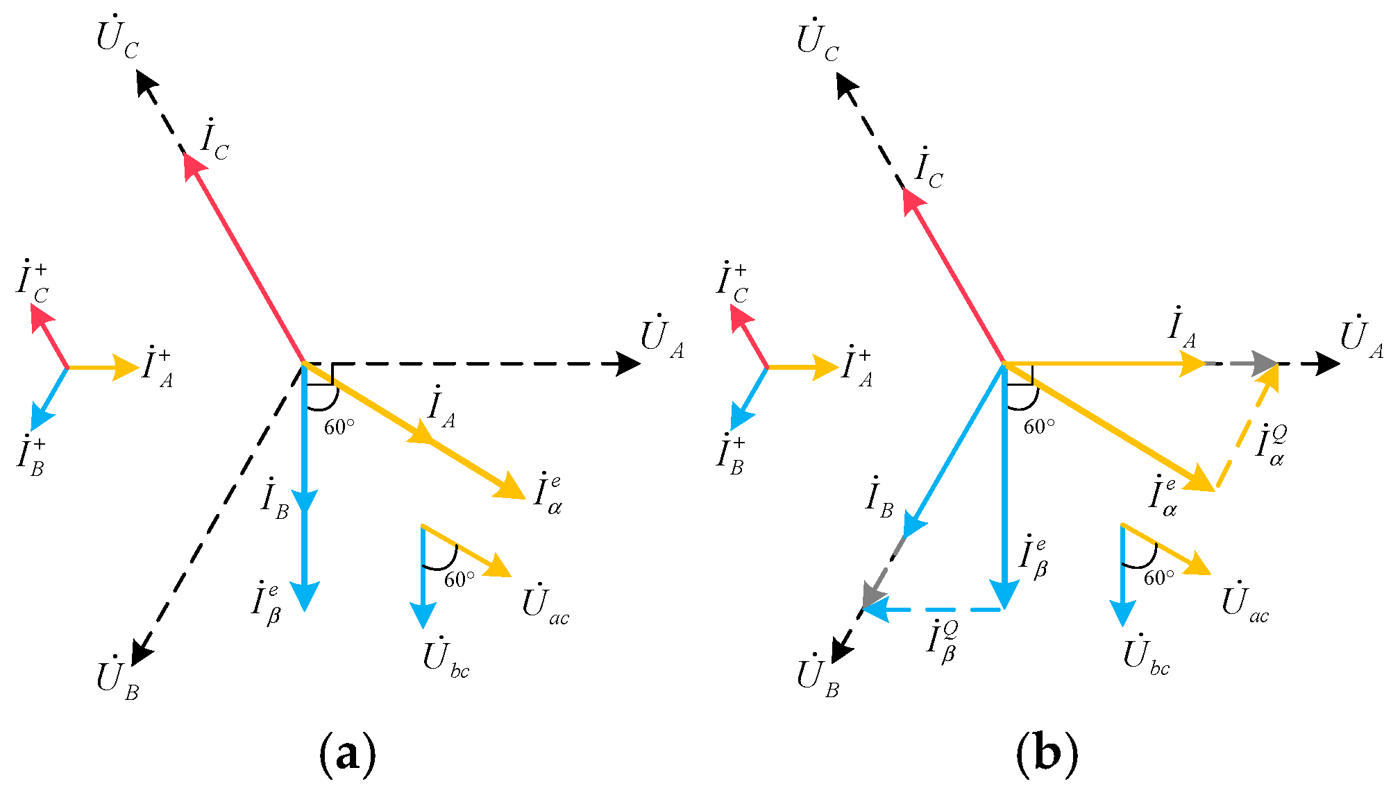
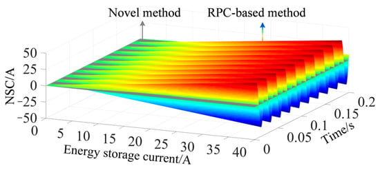
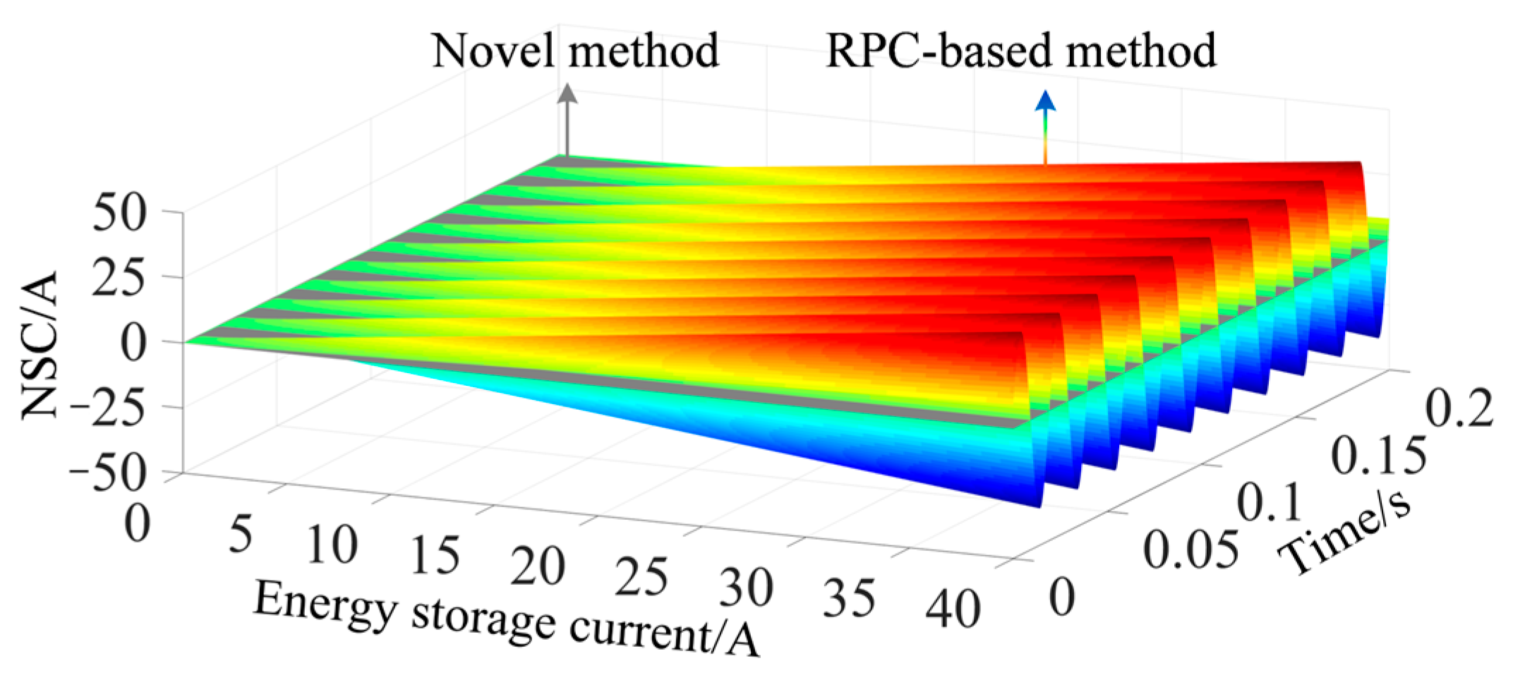
When the active power is absorbed from both arms α and β, the phase diagram of the relevant currents is shown in Figure 4. , , and are three-phase currents. and are energy storage currents. From Figure 4a, we can see that the three-phase current is unbalanced. The NSC generated by the RPC-based method when absorbing energy from the power grid is shown in Figure 5. According to the RPC imbalance compensation principle, in order to prevent the energy storage equipment from generating NSC when the equipment absorbs active power from both power supply arms, appropriate reactive power must be compensated, which is shown in Figure 4b. and are reactive power compensation currents. Assume that the RMS of is and the RMS of is . Then, the RMS of should be . The capacity of the equipment for energy storage should be as follows:
Figure 4.
Phase diagrams of the energy storage system based on RPC. (a) The three-phase current and energy storage currents; (b) reactive power compensation based on the RPC imbalance compensation principle.
Figure 5.
The NSC generated by different methods when absorbing energy from the power grid.
The capacity of the equipment for energy storage and imbalance compensation should be as follows:
In order to prevent the energy storage equipment from generating NSC when the equipment absorbs active power from both power supply arms, the percentage of additional imbalance compensation capacity required for the equipment is as follows:
When the active power is absorbed from a single arm, according to the RPC imbalance compensation principle, such a situation will be changed so that the active power is absorbed from both power supply arms instead of one.
It should be noted that the 15.47% capacity increment calculated in Equation (16) represents the baseline penalty under pure and symmetrical energy storage operations. To fully address the capacity differences under complex working conditions, a dynamic sensitivity analysis considering traction loads, braking power, and load imbalance degrees is necessary. Topologically, under the specific and rare condition of pure, perfectly symmetrical regenerative braking from both arms, the traditional RPC method inherently requires less capacity. By being installed on the secondary traction arms, the RPC locally absorbs the braking energy, resulting in zero net power flowing through the V/V transformer and zero imbalance injected into the primary grid.
However, practical high-speed railway operations are dominated by highly asymmetric and dynamic hybrid loads. For the traditional RPC, which consists of single-phase converters, its apparent capacity strictly follows . In hybrid conditions, when absorbing active power (), the RPC is forced to inject additional reactive power () to prevent grid-side imbalance. This forced directly superimposes with the reactive power required for the original imbalance compensation (). Consequently, the required capacity for the worst-case single-phase arm expands non-linearly:
In contrast, the proposed novel method manages energy storage using purely positive-sequence active power and imbalance compensation using purely negative-sequence apparent power at the grid side. According to the symmetrical component theory, positive- and negative-sequence currents are mathematically orthogonal. Therefore, the total required apparent capacity of the three-phase converter is simply the root-sum-square of the two sequence capacities:
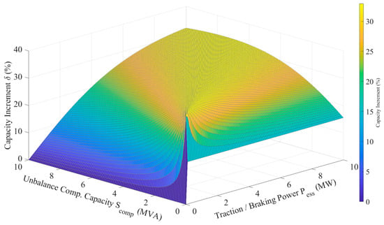
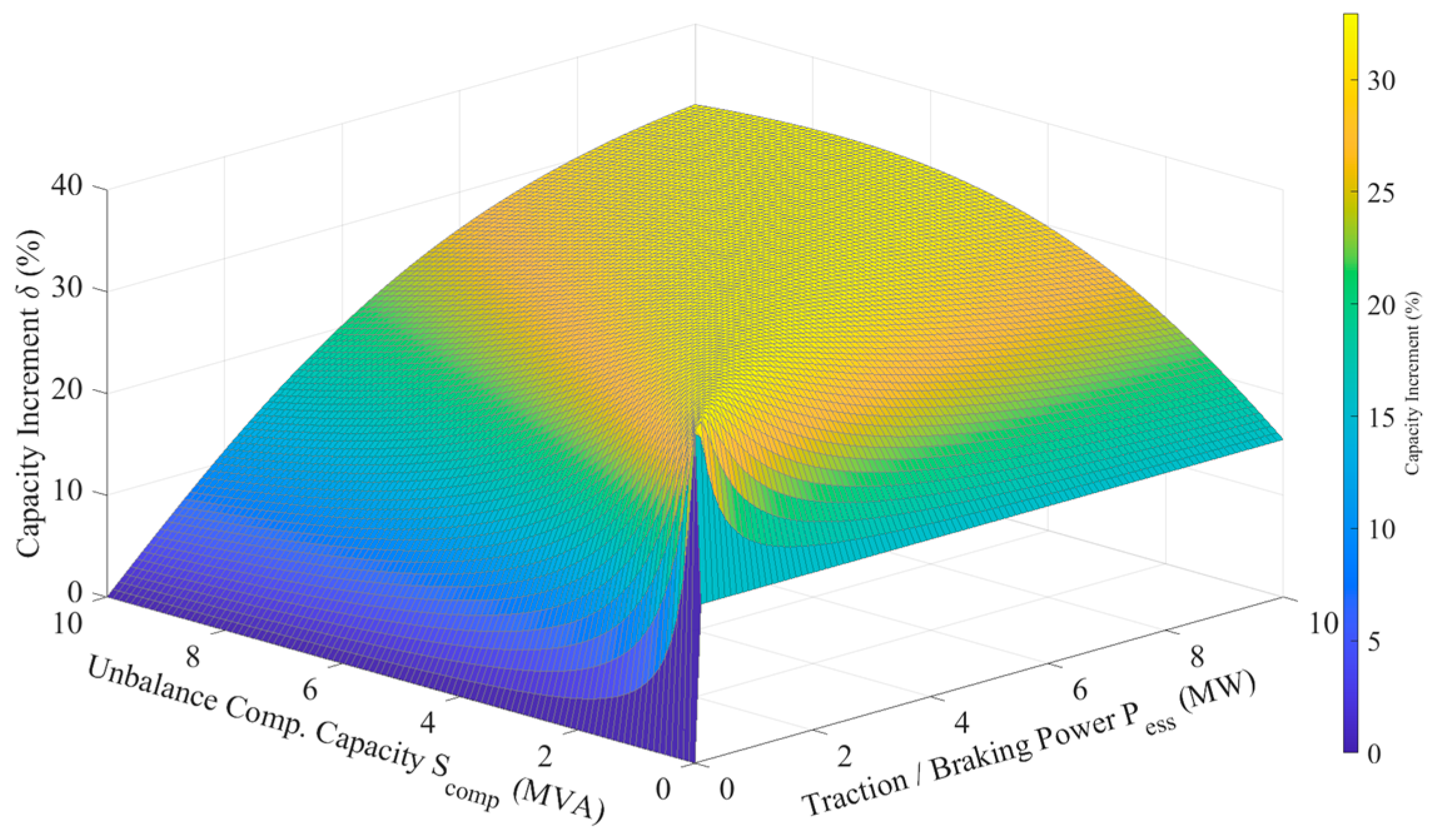
Due to this complete sequence decoupling, the novel method avoids the scalar superposition of reactive power found in the traditional RPC. To map these electrical variables to practical high-speed railway operations, the energy storage active power () directly corresponds to the net traction load or regenerative braking power generated by the trains. Meanwhile, the imbalance compensation demand () is strictly determined by the imbalance degree between the traction loads on the two power supply arms. Therefore, Figure 6 comprehensively illustrates how the capacity increment percentage fluctuates under various combinations of traction loads, braking power, and imbalance degrees, highlighting the economic and capacity superiority of the proposed topology in realistic hybrid conditions.
Figure 6.
Sensitivity analysis of capacity increment percentage under various hybrid working conditions.
4.2. Quantitative Techno-Economic and Volume Comparison
To validate the engineering feasibility of the proposed topology, a quantitative comparison is conducted using a standard 2 MW traction power supply system. The evaluation utilizes commercially available industrial data to ensure authenticity.
4.2.1. Volume Evaluation
While a wide variety of mainstream IGBT modules are utilized in railway applications, this paper selects the 1700 V/1500 A IGBT module from the Infineon PrimePACK 3 (Infineon Technologies AG, Neubiberg, Germany) series as a representative benchmark to conduct a quantitative analysis of system volume and sets the system-level volume power density at approximately 6 MW/m3 (equivalent to 6 kW/L) aligning with the established packaging standards for typical Si IGBT-based high-power traction converters [32].
The proposed method uses a standard three-phase converter comprising three phase legs, which adopts the cascading method in practical engineering applications (6× IGBT modules). Its volume is calculated as follows:
In contrast, the traditional RPC requires two single-phase converters comprising four phase legs, which also adopt the cascading method in practical engineering applications (8× IGBT modules). Accounting for the 33.3% leg count increase and the 15.47% required capacity expansion, the RPC converter volume expands to the following:
For the magnetic components, the baseline is established using a commercial 2 MW medium-voltage standard three-phase dry-type transformer, which occupies a volume of 9.47 m3 (an estimated value based on typical commercial dry-type transformers with protective enclosures). The proposed method utilizes this standard design directly. Conversely, the RPC method requires complex single-phase isolation structures, which typically incur a 15% structural volume overhead compared to shared-core designs. Compounding this overhead with the 15.47% capacity over-sizing, the RPC transformer volume is determined by the following:
Consequently, the proposed method reduces the overall installation volume from 13.08 m3 to 9.80 m3, achieving a 25.1% reduction.
4.2.2. Hardware Cost Evaluation
The economic assessment relies on typical capital expenditure (CAPEX) distributions for megawatt-scale power quality equipment, where magnetic components and power converters account for 40% and 60% of the core hardware cost, respectively. By setting the proposed method’s base cost index at 100%, the RPC cost indexes are derived based on its structural overheads and capacity expansion:
As calculated, the traditional RPC reaches a normalized hardware cost of 133.1%. Therefore, the proposed topology achieves a hardware cost reduction of 24.9%. Table 2 summarizes the quantitative findings, demonstrating the superior techno-economic viability of the novel method.
Table 2.
Quantitative comparison between RPC and the proposed method (2 MW benchmark).
5. Control Method
5.1. Decoupling Control Principle for Energy Storage and Imbalance Compensation
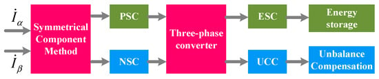
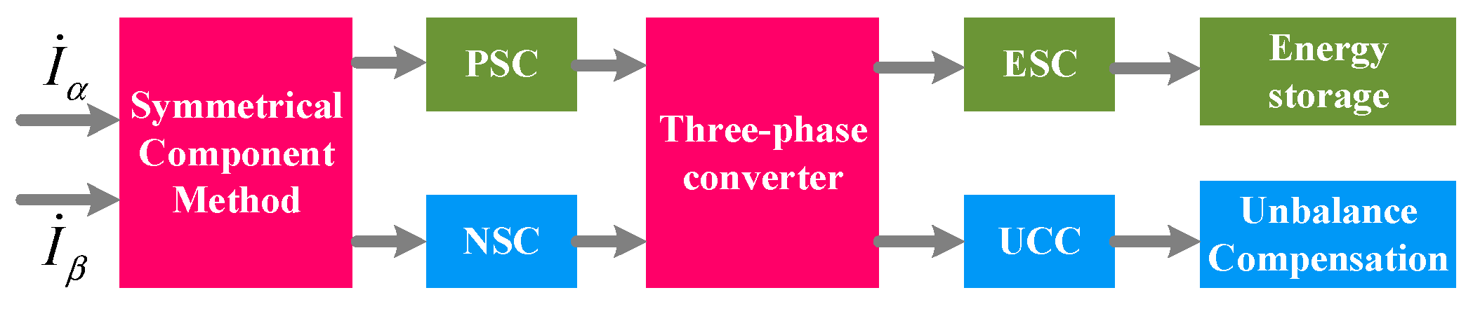
The decoupling control principle of the energy storage and imbalance compensation of the high-speed railway is shown in Figure 7.
Figure 7.
Control principle diagram.
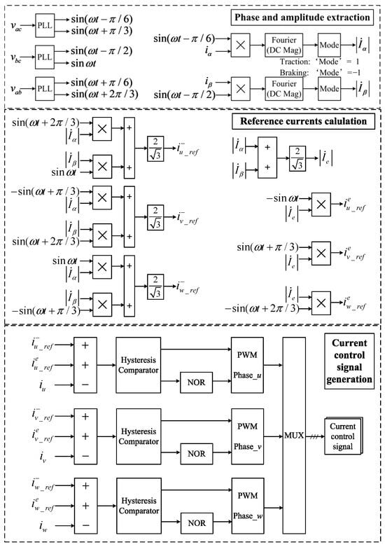
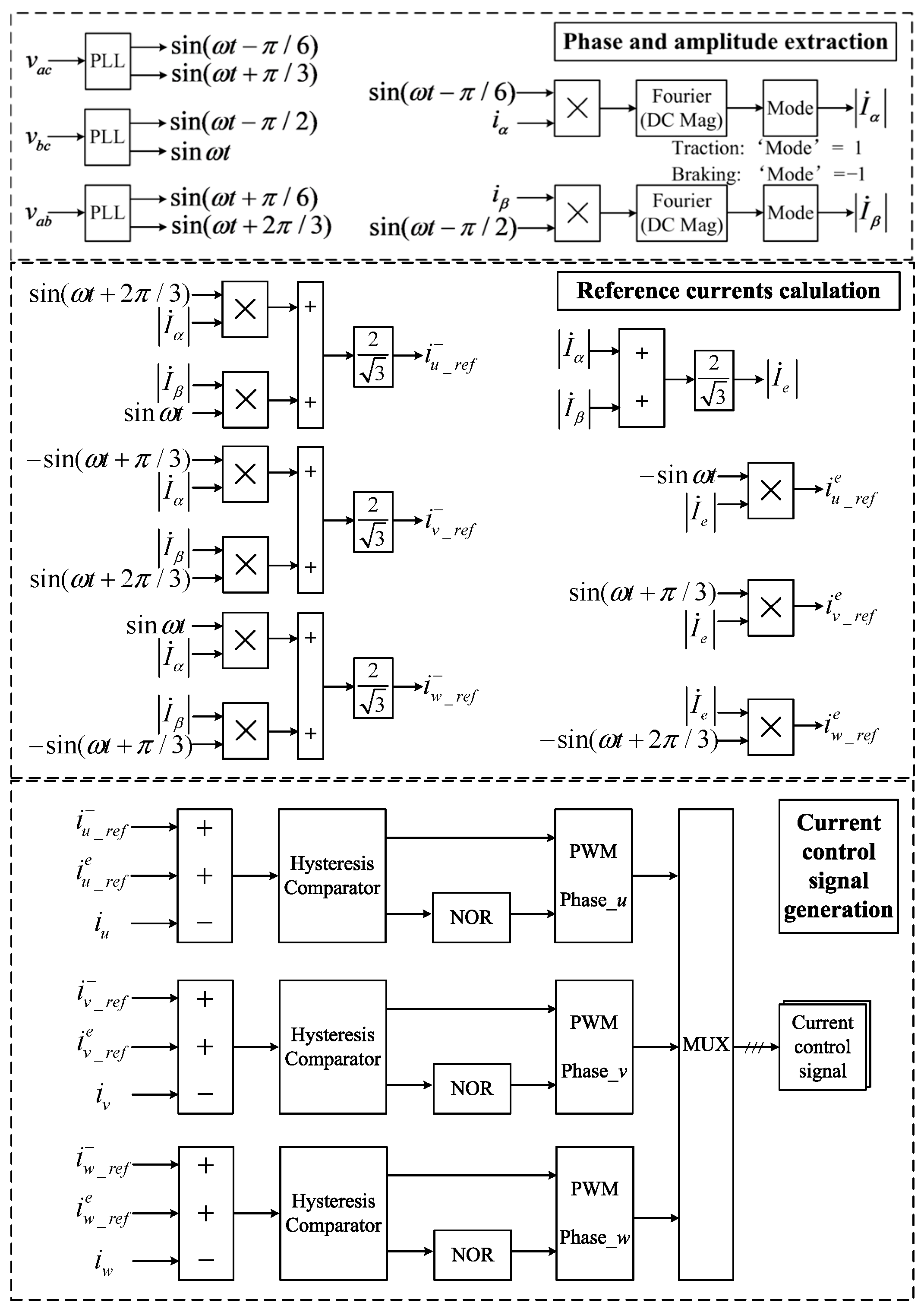
Firstly, detect the load currents of both traction power supply arms which are and . Secondly, substitute the load currents into Equation (2), from which the three-phase current of the power grid can be derived. Thirdly, decompose the three-phase current into PSC and NSC. Then, the UCC and ESC can be deduced through Table 1, according to the energy storage and imbalance compensation principle. Next, the total output reference current of the three-phase converter can be derived by Equation (13). Finally, the three-phase converter injects the total three-phase current into the traction system, of which the ESC component is used for energy storage and the UCC component is used for imbalance compensation. The specific control strategy is shown in Figure 8.
Figure 8.
Specific control strategy.
5.2. Energy Management Strategy of Hybrid Energy Storage System
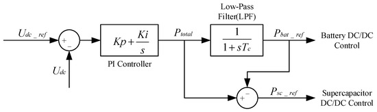
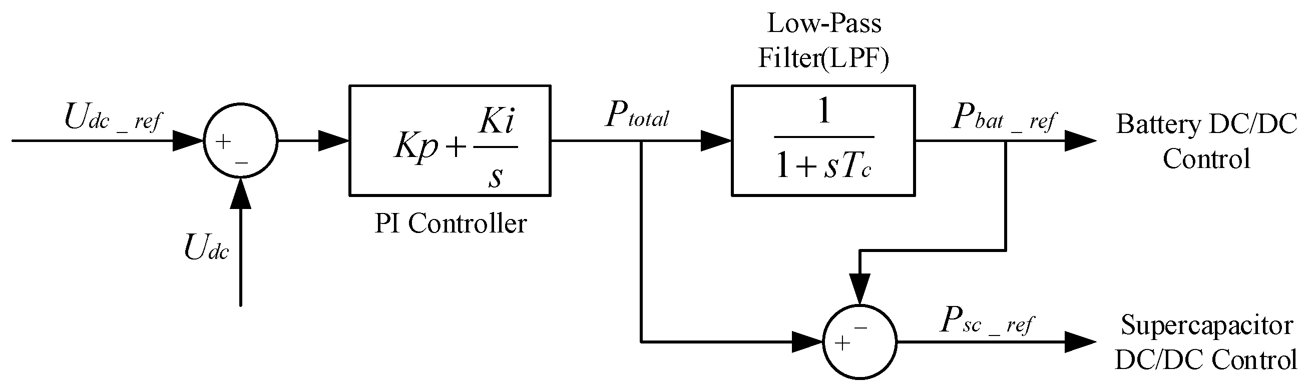
To fully exploit the complementary characteristics of the supercapacitor and the battery within the hybrid energy storage system (HESS), a classic Low-Pass Filter (LPF)-based power distribution strategy is adopted in the DC side [33,34].
During train operation, the active power exchanged by the AC-side converter causes fluctuations in the DC-link voltage. To maintain the DC-link voltage at its reference value (e.g., 400 V in this system), an outer-loop PI voltage controller calculates the total required energy storage power in real time.
Subsequently, the power reference for the battery is extracted by passing through a first-order LPF, while the remaining transient power is dynamically allocated to the supercapacitor . The specific power distribution logic can be expressed as follows:
where represents the time constant of the LPF. The battery is responsible for compensating for low-frequency, steady-state energy variations, whereas the supercapacitor absorbs or releases the high-frequency, transient regenerative braking power. Finally, these power references are tracked by their respective bidirectional DC/DC converters. This internal DC energy management guarantees a stable DC-link voltage, which provides a solid physical foundation for the proposed AC-side imbalance and energy decoupling control. The block diagram of the LPF-based energy management strategy for the HESS is shown in Figure 9.
Figure 9.
LPF-based energy management strategy for the HESS.
6. Simulation
6.1. Decoupling Principle
To validate the decoupling principle of the proposed method, the simulation model is constructed according to Figure 1. The initial traction load of each power supply arm is 3 MW. Firstly, only the PSC is changed to observe the change in NSC. Then, only the NSC is changed to observe the change in PSC. Finally, the traction load changed to 2 MW to observe the change in PSC and NSC.
The simulation results are shown in Table 3. The results indicate that according to the novel method based on the decoupling principle, the changing of the PSC does not affect the NSC, and vice versa. The results also show that according to the RPC method, the changing of the load affects both PSC and NSC.
Table 3.
RMS of the changing PSCs and NSCs.
6.2. Application Under Different Working Conditions
To verify the effectiveness and flexibility of the proposed method under different working conditions, the traction load configuration is shown in Table 4.
Table 4.
Parameter of the load configuration.
6.2.1. Condition A
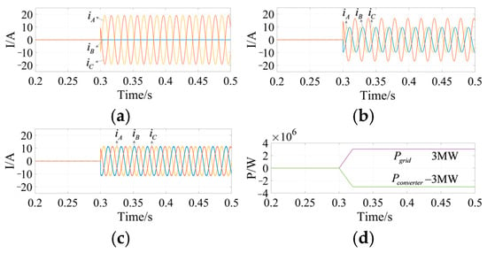
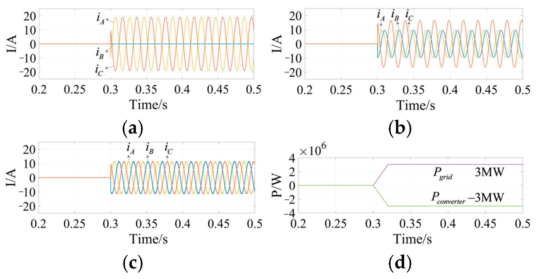
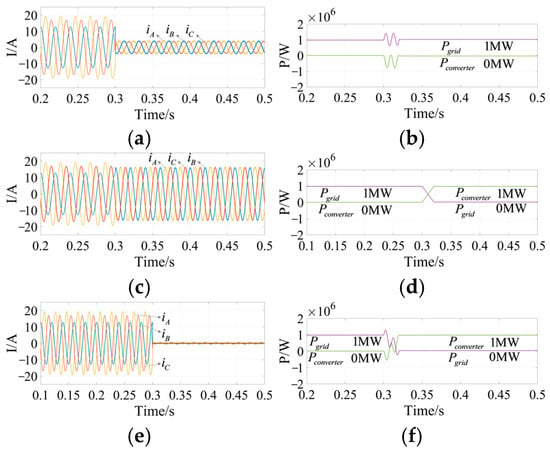
There are no trains operating at the power supply arms, and the imbalance compensation and energy storage equipment absorb active power from the three-phase power supply grid to minimize the peak power requirements of the traction transformer in case the RBE is not sufficient. From Figure 10 and Table 5, we can see that RPC’s absorption of active power from one power supply arm will cause the imbalance issue, and the current imbalance factor is 100%. Meanwhile, RPC’s absorption of active power from both power supply arms will also cause the imbalance issue, and the current imbalance factor is 50%. However, when the novel method absorbs active power, the three-phase current of the power grid is balanced.
Figure 10.
Three-phase current waveforms of the power grid. (a) RPC absorbs active power from one power supply arm; (b) RPC absorbs active power from both power supply arms; (c) the novel method absorbs active power; and (d) the active power of the power grid and converter.
Table 5.
RMS of three-phase currents of the power grid.
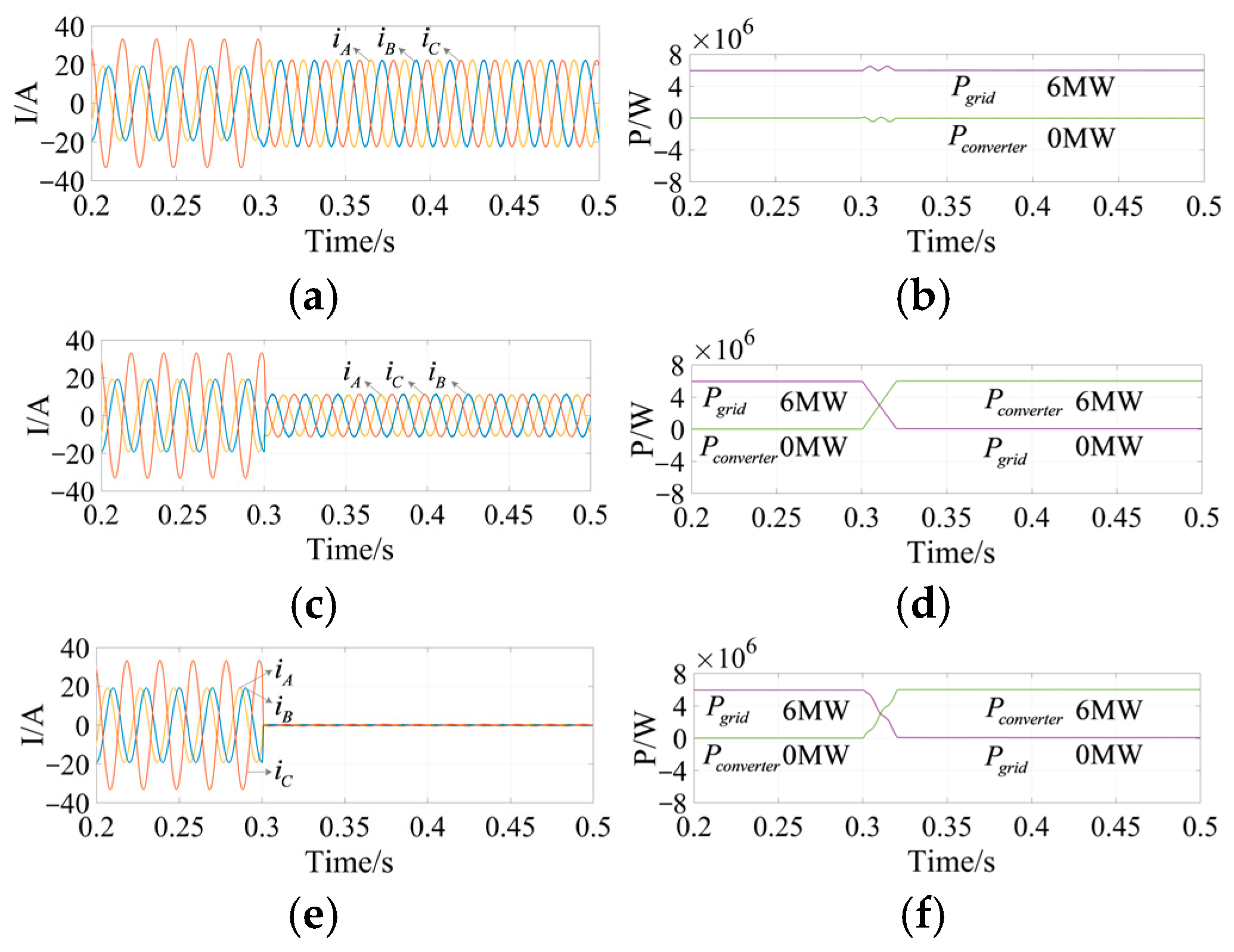
6.2.2. Condition B
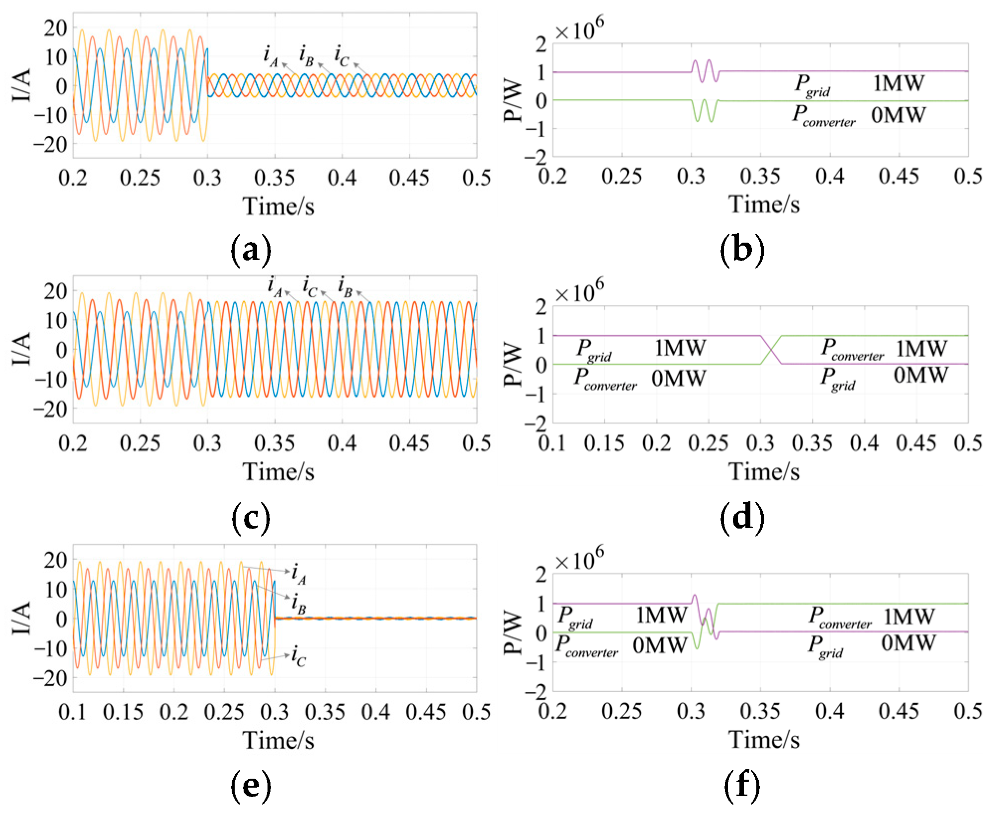
The trains at power supply arms α and β are both in traction mode, and each of their traction powers is 3 MW, as shown in Table 4. Figure 11a,b show that the novel method can compensate for imbalance alone well, and the equipment outputs no active power. Figure 11c,d show that the novel method by itself can release energy to reduce the active power of the traction transformer (same as the active power of the power grid) well. Figure 11e,f show that the novel method can compensate for imbalance and release energy well at the same time.
Figure 11.
Three-phase current waveforms under Condition B. (a) Compensating for imbalance alone; (b) the active power of the power grid and converter compensating for imbalance alone; (c) releasing energy alone; (d) the active power of the power grid and converter releasing energy alone; (e) compensating for imbalance and releasing energy; and (f) the active power of the power grid and converter compensating for imbalance and releasing energy.
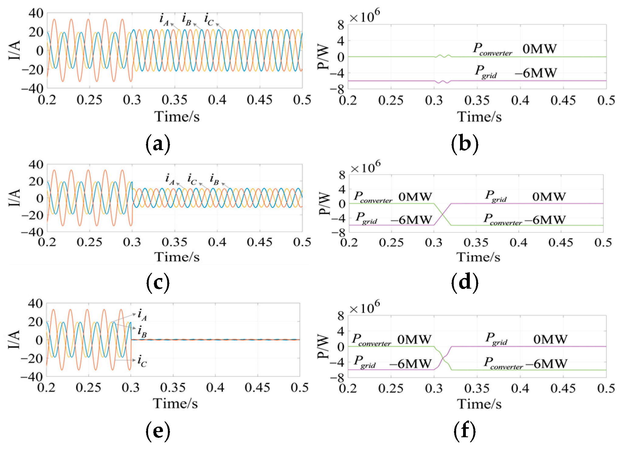
6.2.3. Condition C
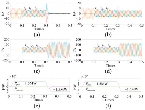
The trains at power supply arms α and β are both in braking mode, and both of their braking powers are , as shown in Table 4. Figure 12a,b illustrate that the novel method can compensate for imbalance alone well and the equipment absorbs no active power. Figure 12c,d show that the novel method can absorb the RBE well all alone. Figure 12e,f show that the novel method can compensate for imbalance and absorb the RBE well in the meantime.
Figure 12.
Three-phase current waveforms under Condition C. (a) Compensating for imbalance alone; (b) the active power of the power grid and converter compensating for imbalance alone; (c) storing energy alone; (d) the active power of the power grid and converter storing energy alone; (e) compensating for imbalance and storing energy; and (f) the active power of the power grid and converter compensating for imbalance and storing energy.
6.2.4. Condition D
The train at arm α is in traction mode () and the train at arm β is in braking mode (), as shown in Table 4. Figure 13a,b show that the novel method can compensate for imbalance alone well, and the equipment outputs no active power. Figure 13c,d show that the novel method can release energy to reduce the active power of the traction transformer alone well. Figure 13e,f show that the novel method can compensate for imbalance and release energy well at the same time.
Figure 13.
Three-phase current waveforms under Condition D. (a) Compensating for imbalance alone; (b) the active power of the power grid and converter compensating for imbalance alone; (c) releasing energy alone; (d) the active power of the power grid and converter releasing energy alone; (e) compensating for imbalance and releasing energy; and (f) the active power of the power grid and converter compensating for imbalance and releasing energy.
6.2.5. Condition E
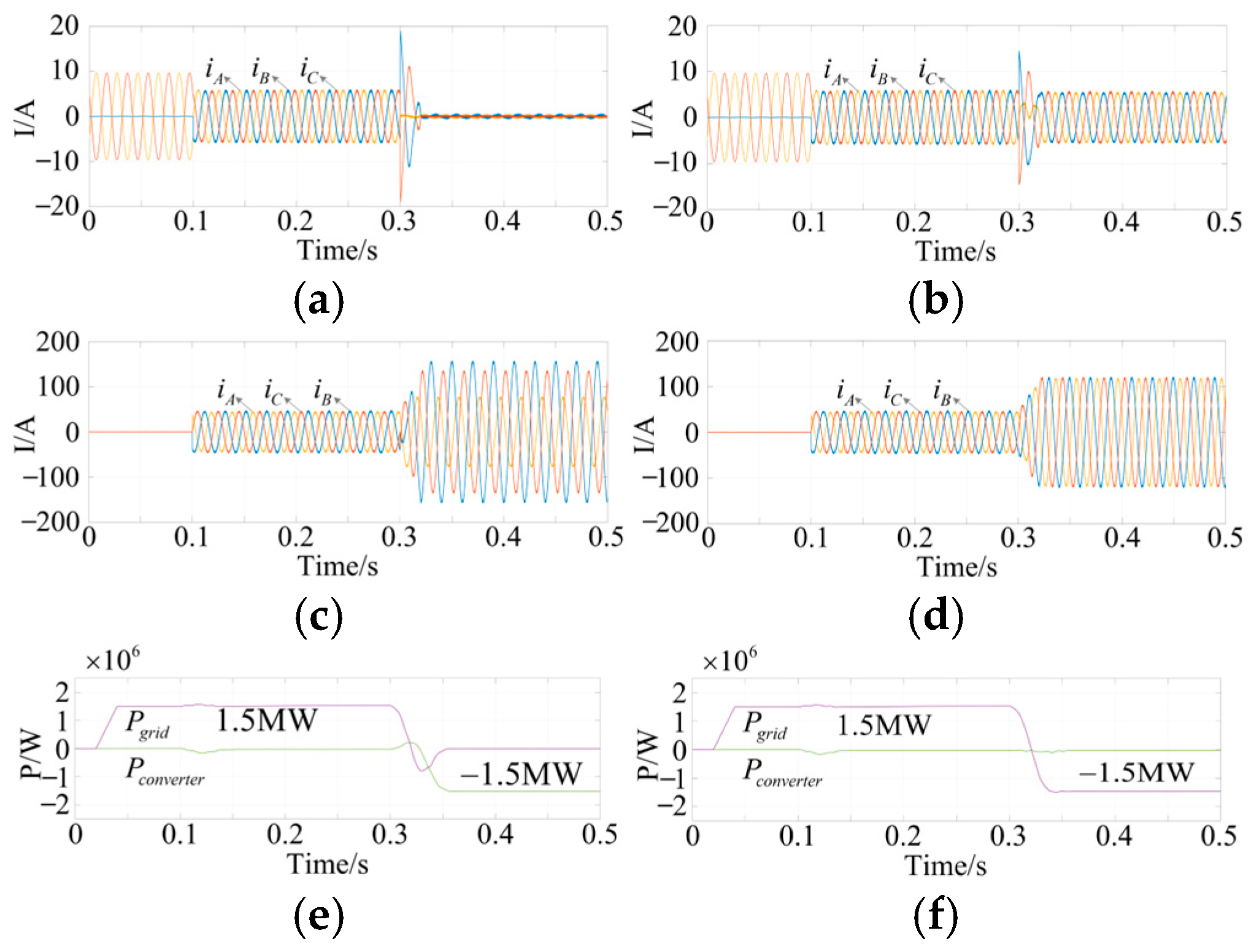
While the preceding conditions validate the steady-state decoupling mechanisms, actual high-speed railway operations involve frequent and drastic load fluctuations. To verify the transient tracking capability and the decoupled control superiority of the proposed method under dynamic nonlinear conditions, a severe dynamic step-change scenario (Condition E) is supplemented.
As illustrated in Figure 14, an unbalanced traction load of 1.5 MW is initially applied to arm α. At t = 0.1 s, the compensator is activated, instantly restoring the asymmetrical grid currents to a balanced state. Subsequently, at t = 0.3 s, a severe dynamic disturbance occurs: a 3 MW regenerative braking load is abruptly connected to arm β, shifting the system into a severe hybrid condition. To comprehensively demonstrate the flexibility of the proposed strategy, this transient process is simulated under two distinct operational modes:
Figure 14.
Dynamic response waveforms under the severe load step-change scenario. (a) Three-phase currents of the power grid under full compensation mode; (b) three-phase currents of the power grid under imbalance-compensation-only mode; (c) output three-phase compensation currents of the converter under full compensation mode; (d) output three-phase compensation currents of the converter under imbalance-compensation-only mode; (e) the active power of the power grid and converter under full compensation mode; and (f) the active power of the power grid and converter under imbalance-compensation-only mode.
- Full Compensation Mode (Figure 14a,c,e): The converter is controlled to compensate for the imbalance while simultaneously absorbing the net regenerative braking energy. As shown in Figure 14e, following the step change at 0.3 s, the converter active power () rapidly tracks to absorb 1.5 MW, causing the net grid power () to smoothly drop to zero. Correspondingly, the grid currents (Figure 14a) transiently fluctuate but quickly converge to near zero within 40 ms.
- Imbalance-Compensation-Only Mode (Figure 14b,d,f): The converter is controlled to exclusively compensate for the negative-sequence imbalance. Following the step change at 0.3 s, the converter refrains from absorbing active energy (Figure 14f, remains zero). Consequently, the net −1.5 MW active power is entirely fed back into the primary grid. Crucially, despite the severe active power surge and imbalance disturbance, the grid-side currents (Figure 14b) regain perfect three-phase symmetry within fewer than two fundamental cycles.
This comparative dynamic analysis physically proves that the proposed topology allows for the completely decoupled control of positive-sequence active power and negative-sequence imbalance, demonstrating its exceptionally rapid transient response and engineering robustness.
7. Experiment
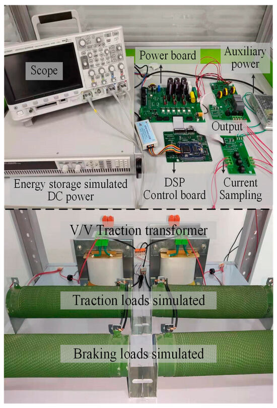
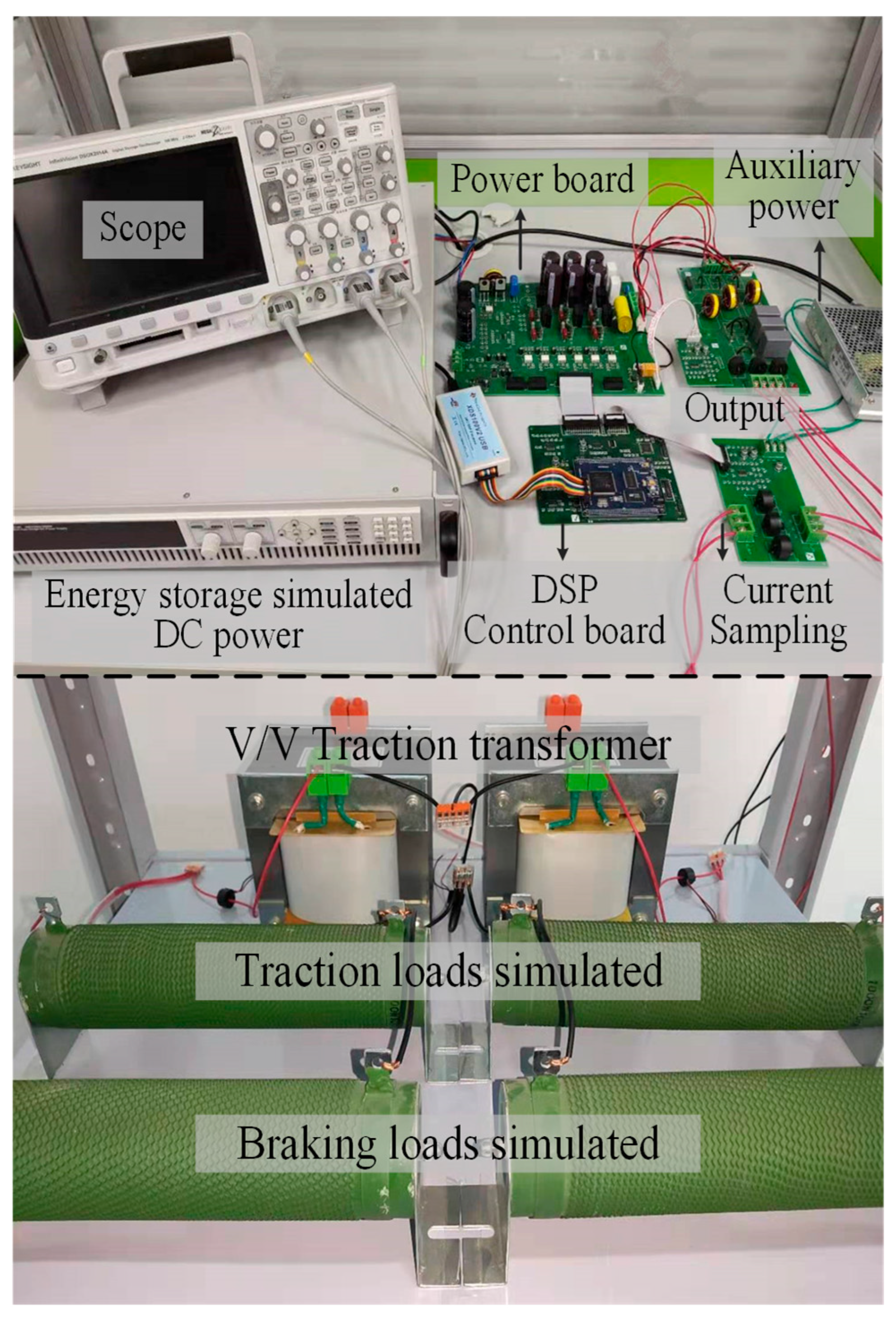
To further validate the effectiveness and flexibility of the novel method, a small capacity experiment platform is established, as shown in Figure 15. The experiment parameters are shown in Table 6. DSP28335 (Texas Instruments, Dallas, TX, USA) is used to sample signals, calculate the reference currents, and output the PWM control signals. IT-M3600 (ITECH Electronic Co., Ltd., New Taipei City, Taiwan) power supply is used as the DC power which can absorb and release energy. Resistances are used to simulate traction load. Resistances and AC power supply (380 V) in series are used to simulate the braking load. Then, the novel method is verified by experiments under different conditions.
Figure 15.
The experiment platform.
Table 6.
Experiment parameters.
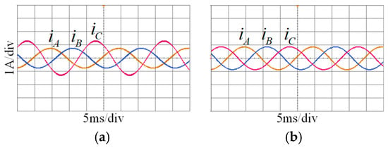
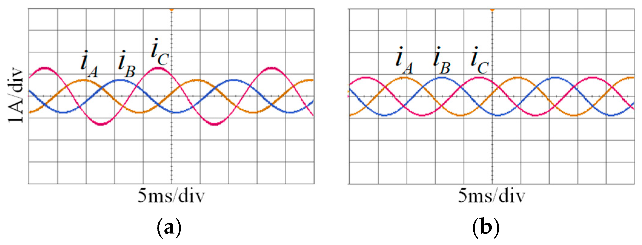
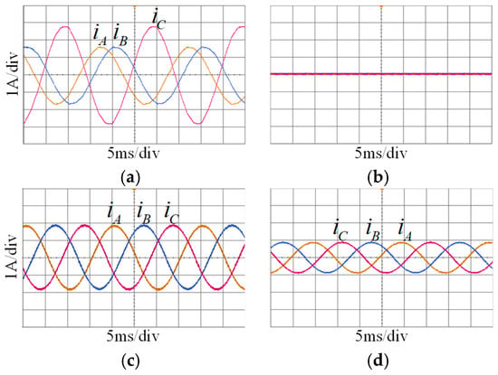
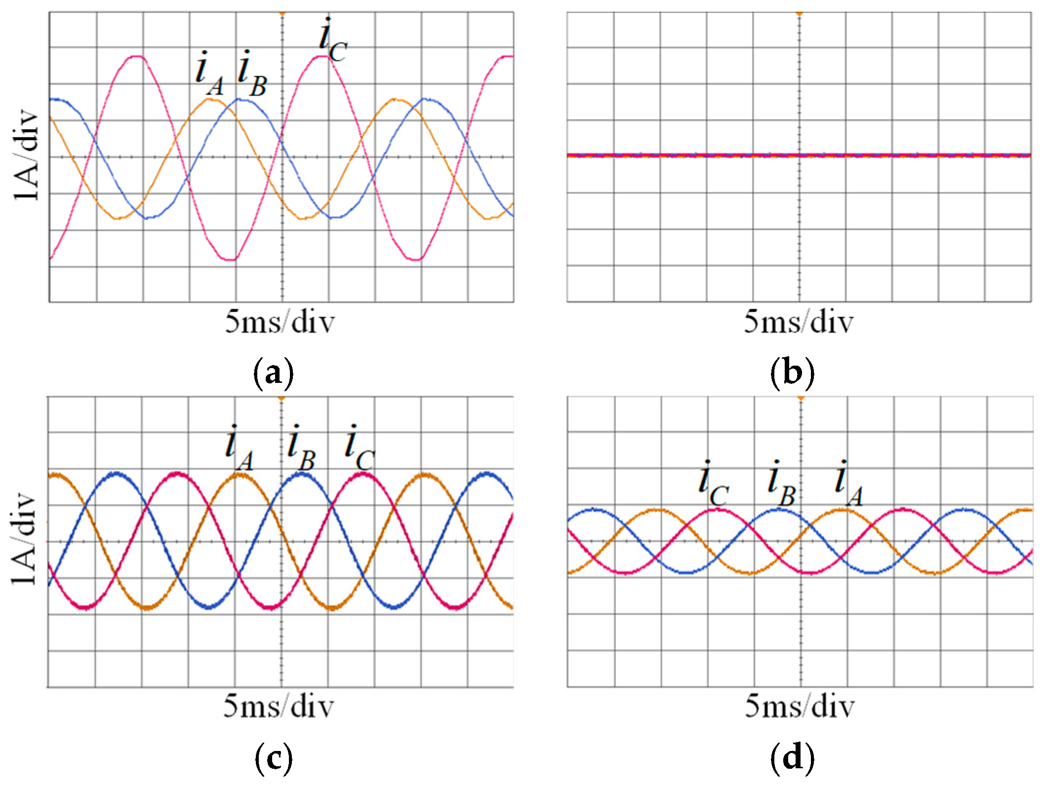
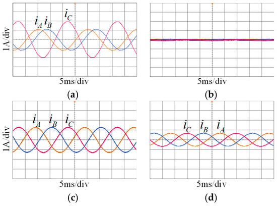
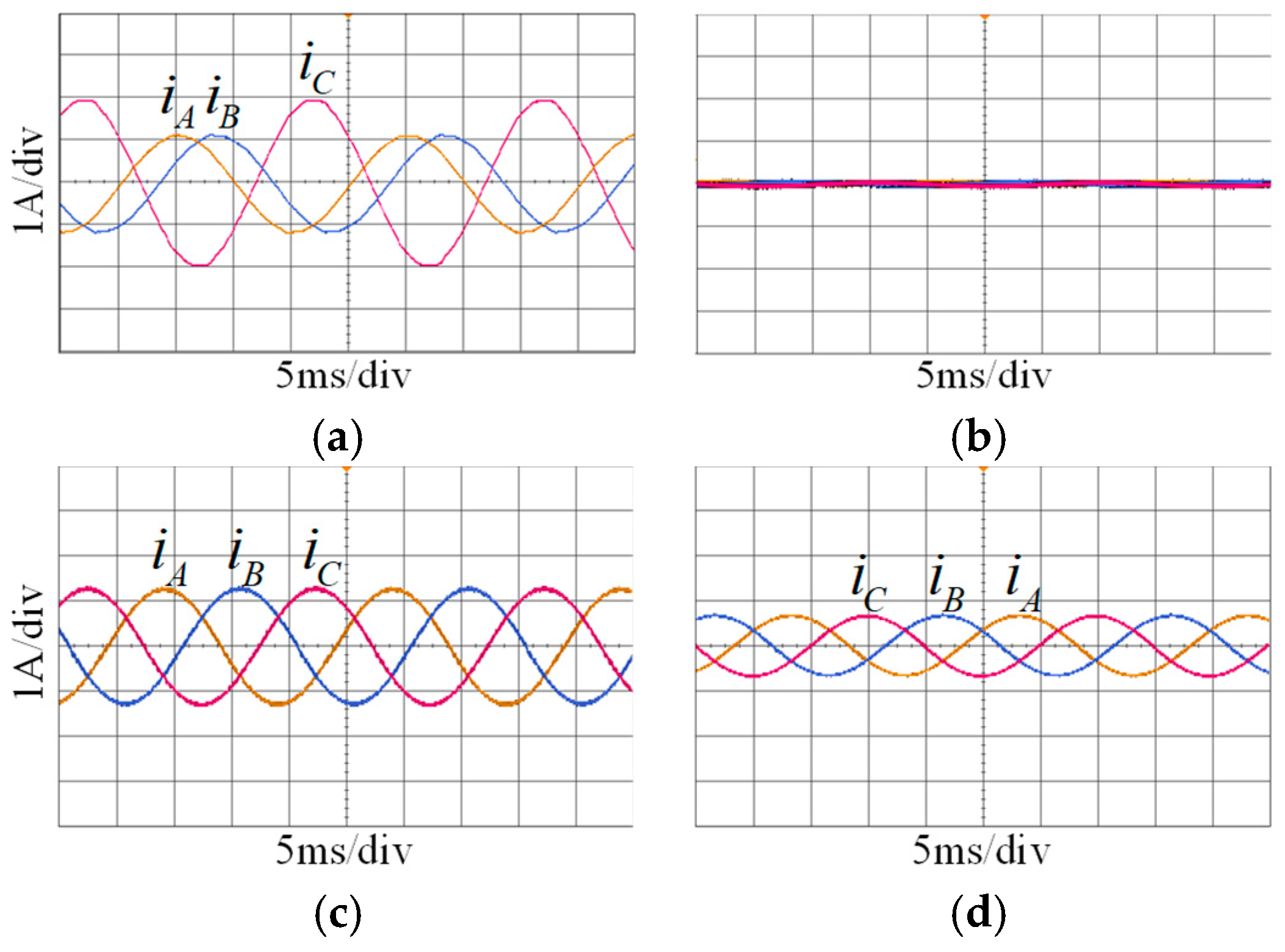
Figure 16 shows three-phase current waveforms under Condition A. Both the RPC-based method and the novel method absorb active power (400 W) from the power grid. The RPC-based method will cause the imbalance issue and the novel method will not. Figure 17, Figure 18 and Figure 19 show three-phase current waveforms under Conditions B, C, and D. We can see that the novel method can compensate for the unbalanced current and absorb (release) energy in different working conditions as needed, discretionarily. The experiment results are in accordance with the analysis of the theory and simulations, and they prove the effectiveness and flexibility of the novel method.
Figure 16.
Three-phase current waveforms of the power grid with no loads. (a) RPC absorbs active power from the power grid (400 W); (b) the novel method absorbs active power from the power grid (400 W).
Figure 17.
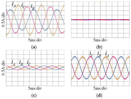
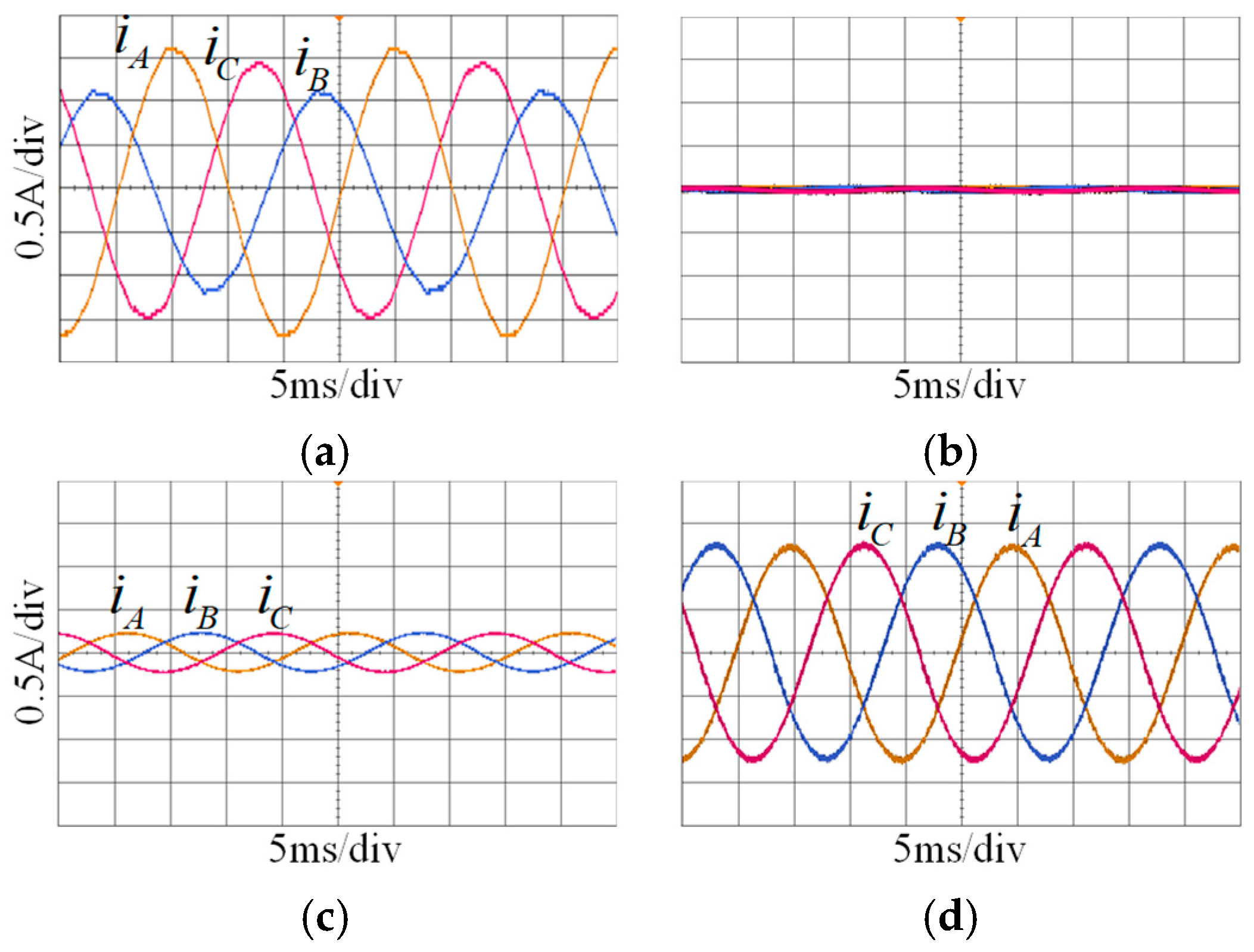
Three-phase current waveforms of the power grid when the trains are both in traction mode. (a) No imbalance compensation and energy releasing; (b) compensating for imbalance and releasing energy; (c) compensating for imbalance alone; and (d) releasing energy alone.
Figure 18.
Three-phase current waveforms of the power grid when the trains are both in braking mode. (a) No imbalance compensation and energy absorbing; (b) compensating for imbalance and absorbing energy; (c) compensating for imbalance alone; and (d) absorbing energy alone.
Figure 19.
Three-phase current waveforms of the power grid when one train is in traction mode and the other is in braking mode. (a) No imbalance compensation and energy releasing; (b) compensating for imbalance and releasing energy; (c) compensating for imbalance alone; and (d) releasing energy alone.
8. Conclusions
As the imbalance compensation and energy storage functions are coupled in the RPC-based method, a novel method which can decouple the two functions is presented in this paper. The novel method is based on a three-phase converter and a transformer, and the RPC method is based on two single-phase (full-bridge) converters and a transformer. Therefore, the equipment of the novel method is of lower costs and requires smaller installation space, specifically lowering the core hardware cost by 24.9% and reducing the total system volume by 25.1%. The decoupling principle and control strategy are discussed in detail. The novel method can compensate for unbalanced current and absorb (release) energy well, under different conditions, as needed, discretionarily. While the capacity requirements of the traditional RPC and the proposed method are identical under pure single-task operations, the traditional RPC suffers from significant cross-coupling overheads in hybrid scenarios. To achieve the same effect as the new method, the capacity of traditional equipment increases by 15.47% under nominal hybrid conditions and can surge by over 30% in worst-case scenarios.
Author Contributions
W.X. and F.X. contributed to the writing of the original draft. J.Y. helped with this paper’s review and editing. X.F. helped with the funding acquisition and data curation of this paper. H.T. contributed to the investigation and resources of this paper. Y.S. provided support in visualization and methodology. All authors have read and agreed to the published version of the manuscript.
Funding
This research was funded by Science and Technology Project of State Grid Corporation of China, grant number 5230HQ25001Q-395-ZN.
Data Availability Statement
The original contributions presented in this study are included in the article. Further inquiries can be directed to the corresponding author.
Acknowledgments
The authors would like to thank the Yuan Jiaxin research group from the School of Electrical Engineering and Automation at Wuhan University for providing the equipment and venue support, which enabled our research to proceed smoothly. The authors would further like to thank Zhou Hang and Chen Jiangbo for their significant theoretical guidance in the research.
Conflicts of Interest
The authors declare no conflicts of interest.
References
- Hasanpour, N.; Khajehoddin, S.A. Energy Conservation Versus Charge Conservation Law for Modeling and Analyzing Cell Equalizers. IEEE Trans. Power Electron. 2023, 38, 14638–14651. [Google Scholar] [CrossRef] [Scilit]
- Wang, X.; Zhang, H.; Sun, S.; Gao, Y.; Jin, B. Energy Recovery and Utilization Efficiency Improvement for Motor-Driven System Using Dynamic Energy Distribution Method. IEEE Trans. Veh. Technol. 2022, 71, 10327–10336. [Google Scholar] [CrossRef] [Scilit]
- Xu, W.; Zhao, C.; Dai, X.; Yuan, Z.; Zhang, T.; Wang, T.; Ren, Y.; Lv, Y. Parallel Dispatching: An ACP-Based High-Speed Railway Intelligent Dispatching System. IEEE Trans. Intell. Veh. 2024, 9, 1146–1160. [Google Scholar] [CrossRef] [Scilit]
- Chen, J.; Ge, Y.; Wang, K.; Hu, H.; He, Z.; Tian, Z.; Li, Y. Integrated Regenerative Braking Energy Utilization System for Multi-Substations in Electrified Railways. IEEE Trans. Ind. Electron. 2023, 70, 298–310. [Google Scholar] [CrossRef] [Scilit]
- Xiao, S.; Wang, Z.; Wu, G.; Guo, Y.; Gao, G.; Zhang, X.; Cao, Y.; Zhang, Y.; Yu, J.; Liu, P.; et al. The Impact Analysis of Operational Overvoltage on Traction Transformers for High-Speed Trains Based on the Improved Capacitor Network Methodology. IEEE Trans. Transp. Electrif. 2024, 10, 364–378. [Google Scholar] [CrossRef] [Scilit]
- Mir, T.N.; Tricoli, P. Power Electronic Autotransformer-Based 3 × 25 kV Network for Power Quality Enhancement in Railway Supply Systems. IEEE Trans. Transp. Electrif. 2024, 10, 4699–4708. [Google Scholar] [CrossRef] [Scilit]
- Wu, C.; Lu, S.; Tian, Z.; Xue, F.; Jiang, L. Energy-Efficient Train Control with Onboard Energy Storage Systems Considering Stochastic Regenerative Braking Energy. IEEE Trans. Transp. Electrif. 2025, 11, 257–274. [Google Scholar] [CrossRef] [Scilit]
- Shen, X.; Wei, H.; Lie, T.T. Management and Utilization of Urban Rail Transit Regenerative Braking Energy Based on the Bypass DC Loop. IEEE Trans. Transp. Electrif. 2021, 7, 1699–1711. [Google Scholar] [CrossRef] [Scilit]
- Chen, J.; Hu, H.; Wang, M.; Ge, Y.; Wang, K.; Huang, Y.; Yang, K.; He, Z.; Xu, Z.; Li, Y.R. Power Flow Control-Based Regenerative Braking Energy Utilization in AC Electrified Railways: Review and Future Trends. IEEE Trans. Intell. Transp. Syst. 2024, 25, 6345–6365. [Google Scholar] [CrossRef] [Scilit]
- Chen, J.; Zhao, Y.; Wang, M.; Wang, K.; Huang, Y.; Xu, Z. Power Sharing and Storage-Based Regenerative Braking Energy Utilization for Sectioning Post in Electrified Railways. IEEE Trans. Transp. Electrif. 2024, 10, 2677–2688. [Google Scholar] [CrossRef] [Scilit]
- Chen, J.; Zhao, Y.; Wang, M.; Yang, K.; Ge, Y.; Wang, K.; Lin, H.; Pan, P.; Hu, H.; He, Z.; et al. Multi-Timescale Reward-Based DRL Energy Management for Regenerative Braking Energy Storage System. IEEE Trans. Transp. Electrif. 2025, 11, 7488–7500. [Google Scholar] [CrossRef] [Scilit]
- Cicek, A.; Şengör, I.; Guner, S.; Karakus, F.; Erenoglu, A.K.; Erdinc, O.; Shafie-Khah, M.; Catalao, J.P.S. Integrated Rail System and EV Parking Lot Operation with Regenerative Braking Energy, Energy Storage System and PV Availability. IEEE Trans. Smart. Grid 2022, 13, 3049–3058. [Google Scholar] [CrossRef] [Scilit]
- Sun, X.; Yao, Z.; Dong, C.; Clarke, D. Optimal Control Strategies for Metro Trains to Use the Regenerative Braking Energy: A Speed Profile Adjustment Approach. IEEE Trans. Intell. Transp. Syst. 2023, 24, 5883–5894. [Google Scholar] [CrossRef] [Scilit]
- Pasupuleti, S.S.; Tummuru, N.R.; Misra, H. Power Management of Hybrid Energy Storage System Based Wireless Charging System with Regenerative Braking Capability. IEEE Trans. Ind. Appl. 2023, 59, 3785–3794. [Google Scholar] [CrossRef] [Scilit]
- Liu, Y.; Yang, Z.; Wu, X.; Lan, L.; Lin, F.; Su, H.; Huang, J. Adaptive Threshold Adjustment Strategy Based on Fuzzy Logic Control for Ground Energy Storage System in Urban Rail Transit. IEEE Trans. Veh. Technol. 2021, 70, 9945–9956. [Google Scholar] [CrossRef] [Scilit]
- Chen, J.; Hu, H.; Ge, Y.; Wang, K.; Huang, W.; He, Z. An Energy Storage System for Recycling Regenerative Braking Energy in High-Speed Railway. IEEE Trans. Power Deliv. 2021, 36, 320–330. [Google Scholar] [CrossRef] [Scilit]
- Zhu, G.; Dong, J.; Grazian, F.; Bauer, P. A Hybrid Modulation Scheme for Efficiency Optimization and Ripple Reduction in Secondary-Side Controlled Wireless Power Transfer Systems. IEEE Trans. Transp. Electrif. 2025, 11, 6840–6853. [Google Scholar] [CrossRef] [Scilit]
- Ge, Y.; Hu, H.; Huang, Y.; Wang, K.; Chen, J.; He, Z. Quadratic Sensitivity Models for Flexible Power Quality Improvement in AC Electrified Railways. IEEE Trans. Power Electr. 2023, 38, 2844–2849. [Google Scholar] [CrossRef] [Scilit]
- Chen, J.; Zhao, Y.; Lin, H.; Wei, Y.; Liu, W.; Guo, Q.; Li, Y.R.; Mantooth, H.A. Analysis and Control of Cascaded Energy Storage System for Energy Efficiency and Power Quality Improvement in Electrified Railways. IEEE Trans. Transp. Electrif. 2024, 10, 1299–1313. [Google Scholar] [CrossRef] [Scilit]
- Luo, P.; Luo, R.; Ma, Q.; Ma, X.; Chen, X. Research on DC Voltage Stability Control of Railway Power Conditioner Based on Impedance Matching Principle. IEEE Trans. Transp. Electrif. 2024, 10, 795–810. [Google Scholar] [CrossRef] [Scilit]
- Wang, K.; Hu, H.; Huang, Y.; Ai, L.; Liu, Y.; Chen, J.; Ge, Y.; He, Z.; Chen, L.; Li, Z. Study on Overvoltage Issues in the Traction Network of Electrified Railways Caused by the Reactive Power: Phenomenon, Analysis, and Solution. IEEE Trans. Transp. Electrif. 2024, 10, 4844–4858. [Google Scholar] [CrossRef] [Scilit]
- Cardoso, J.T.; Jacobina, C.B.; Felinto, A.S.; dos Santos, A.A., Jr.; Corrêa, M.B.R. Single-Phase Transformerless Unified Power Quality Conditioner Based on Three-Leg and Standby Converters. IEEE Trans. Ind. Appl. 2025, 61, 9481–9492. [Google Scholar] [CrossRef] [Scilit]
- Cardoso, J.T.; Jacobina, C.B.; Felinto, A.S.; de Rossiter Corrêa, M.B. Five-Leg Single-Phase Transformerless Unified Power Quality Conditioner. IEEE Trans. Ind. Appl. 2025, 61, 472–486. [Google Scholar] [CrossRef] [Scilit]
- Mochinaga, Y.; Hisamizu, Y.; Takeda, M.; Miyashita, T.; Hasuike, K. Static power conditioner using GTO converters for ac electric railway. In Proceedings of the Conference Record of the Power Conversion Conference, Yokohama, Japan, 19–21 April 1993; pp. 641–646. [Google Scholar]
- Lei, M.; Wang, Y. A Transformerless Railway Power Quality Compensator Based on Cascaded H-Bridge Featuring Reduced Branch Capacity Requirement. IEEE Trans. Power Deliv. 2022, 37, 5443–5453. [Google Scholar] [CrossRef] [Scilit]
- Wen, P.; Zhao, P.; Qiao, K.; Zhang, P.; Li, P. Integrated Optimization Approach for High-Speed Railway Rescheduling with Passenger Transfer and Compensation Mechanisms. IEEE Trans. Intell. Transp. Syst. 2025, 26, 21651–21666. [Google Scholar] [CrossRef] [Scilit]
- Zhu, Z.; Ma, F.; Wang, X.; Deng, L.; Li, G.; Wei, X.; Tang, Y.; Liu, S. Operation Analysis and a Game Theoretic Approach to Dynamic Hybrid Compensator for the V/v Traction System. IEEE Trans. Power Electr. 2019, 34, 8574–8587. [Google Scholar] [CrossRef] [Scilit]
- Ma, F.; Zhu, Z.; Min, J.; Yue, Y.; He, X. Model analysis and sliding mode current controller for multilevel railway power conditioner under the v/v traction system. IEEE Trans. Power Electr. 2019, 34, 1243–1253. [Google Scholar] [CrossRef] [Scilit]
- Guo, P.; Tian, Z.; Yuan, Z.; Zhang, X.-Y.; Sharifi, D. Research on Symmetric Bipolar MMC-M2Tdc-Based Flexible Railway Traction Power Supply System. IEEE Trans. Transp. Electrif. 2024, 10, 1043–1055. [Google Scholar] [CrossRef] [Scilit]
- Li, H.; Sun, Y.; Xie, S.; Xiong, W.; Su, M. Improved Branch Energy Balance Control for Three-Phase to Single-Phase Modular Multilevel Converter for Railway Traction Power Supply. IEEE Trans. Transp. Electrif. 2023, 9, 87–98. [Google Scholar] [CrossRef] [Scilit]
- Cui, G.; Luo, L.; Liang, C.; Hu, S.; Li, Y.; Cao, Y.; Xie, B.; Xu, J.; Zhang, Z.; Liu, Y.; et al. Supercapacitor integrated railway static power conditioner for regenerative braking energy recycling and power quality improvement of high-speed railway system. IEEE Trans. Transp. Electrif. 2019, 5, 702–714. [Google Scholar] [CrossRef] [Scilit]
- Ni, Z.; Li, Y.; Liu, C.; Wei, M.; Cao, D. A 100 kW SiC Switched Tank Converter for Transportation Electrification. IEEE Trans. Power Electron. 2020, 35, 10430–10443. [Google Scholar] [CrossRef] [Scilit]
- Ramos, G.A.; Costa-Castelló, R. Energy Management Strategies for Hybrid Energy Storage Systems Based on Filter Control: Analysis and Comparison. Electronics 2022, 11, 1631. [Google Scholar] [CrossRef] [Scilit]
- Chi, T.N.; Nguyen, B.-H.; Trovão, J.P.F.; Ta, M.C. Effect of Battery/Supercapacitor Hybrid Storage System on Battery Voltage in Electric Vehicles. In Proceedings of the 2022 IEEE Vehicle Power and Propulsion Conference (VPPC), Merced, CA, USA, 1–4 November 2022; pp. 1–6. [Google Scholar]

Disclaimer/Publisher’s Note: The statements, opinions and data contained in all publications are solely those of the individual author(s) and contributor(s) and not of MDPI and/or the editor(s). MDPI and/or the editor(s) disclaim responsibility for any injury to people or property resulting from any ideas, methods, instructions or products referred to in the content. |
© 2026 by the authors. Licensee MDPI, Basel, Switzerland. This article is an open access article distributed under the terms and conditions of the Creative Commons Attribution (CC BY) license.