


Abstract
A dual-band flexible wearable MIMO antenna with two operating modes, namely low-frequency narrowband and high-frequency broadband, is proposed and investigated in this paper. The antenna is based on a polyimide (PI) flexible printed circuit (FPC) substrate and has a compact size (90 mm × 40 mm × 0.1 mm), enabling easy integration into helmet-mounted devices. The antenna elements are fed by a coplanar waveguide (CPW) and integrated with a ground decoupling structure, achieving an isolation of at least 23.4 dB between the two ports across the entire operating frequency band. In addition, the impedance-matching characteristics of the antenna under bending conditions and the Specific Absorption Rate (SAR) of this MIMO antenna in a 1 g human-tissue model at 3.7 GHz and 4.6 GHz were evaluated. The results indicate that the antenna’s key electromagnetic performance remains relatively stable under bending conditions, and the SAR values comply with international limit requirements, verifying its feasibility for application in head-worn terminals. With an impedance bandwidth of −10 dB, this antenna achieves dual-band coverage at 3.42–3.84 GHz (relative bandwidth of 11.6%) and 4.37–7.80 GHz (relative bandwidth of 56.4%), effectively meeting the requirements of 5G/6G communication frequency bands.
1. Introduction
Brain–computer interfaces (BCIs) are cutting-edge interdisciplinary technologies that integrate neuroscience, information engineering, and artificial intelligence. In recent years, they have garnered widespread attention globally and achieved significant advancements. Currently, non-invasive devices typically take the form of physical devices, such as helmets, headbands, and headphones, that capture electroencephalographic (EEG) signals near the scalp, enabling information exchange between the brain and external devices. As wireless communication technology evolves toward sixth-generation mobile communications (6G), higher demands are placed on data transmission rates, transmission reliability, and multi-device connection density. Against this backdrop, brain–computer interface devices also require higher performance standards for their integrated antennas. To support efficient 6G-compatible wireless transmission, antennas need to achieve multi-band coverage and high channel isolation within highly integrated, compact, wearable structures, ensuring stable, reliable, and low-latency data exchange for brain–computer interface systems in complex application scenarios. Therefore, the design needs to balance wearability and comfort while meeting electromagnetic safety SAR limit requirements to prevent potential electromagnetic radiation hazards to the human brain. Compared to single-antenna systems, MIMO antennas offer significantly higher data transmission rates, lower latency, and reduced signal loss [1,2,3,4]. However, during actual engineering deployment and terminal integration, MIMO antennas are constrained by the overall size of head-worn devices, requiring the highly compact integration of multiple radiating elements within a limited physical space. It leads to intensified electromagnetic coupling effects among coexisting radiating elements in the antenna array, resulting in a significant reduction in port isolation. Consequently, it directly reduces MIMO channel capacity and adversely affects the transmission performance and stability of the entire communication system. The existing literature has explored various technical solutions to minimize antenna spacing and overall coupling effects [5,6,7,8,9]. Ref. [6] employs graphene-based frequency-selective surfaces (FSSs) to suppress antenna coupling; while this improves isolation, it lacks sufficient frequency band adaptability and flexible integration capabilities. Ref. [7] achieves coupling suppression through the synergistic effect of grounded branches and electromagnetic band gaps (EBGs), but its complex structure hinders thin and lightweight design; Ref. [10] employs mode cancelation techniques, and Ref. [11] designs ultra-wideband MIMO antennas; however, both struggle to meet the flexibility and miniaturization requirements of BCI wearable applications.
Although domestic and international scholars have conducted extensive research on flexible wearable antennas and achieved significant progress in balancing electromagnetic performance, bending stability, and human electromagnetic safety, existing studies still have some shortcomings. Refs. [12,13,14,15,16,17,18] focus on wearable and 5G communication antennas. Among these, the 5 GHz WBAN wearable meta surface MIMO antenna proposed in Ref. [13] operates at a single frequency and is relatively large in size; Ref. [14] achieves a multi-band fabric antenna design, but its performance adaptability is limited; the Sub-6 GHz 5G wearable fabric MIMO antenna in Ref. [15] supports only a single frequency band; The 5G MIMO array in Ref. [16] exhibits excellent isolation but cannot be used in wearable applications due to its FR-4 rigid substrate, and it suffers from single-band operation and low gain; and Refs. [17,18] developed a single-band BLE antenna and a flexible MIMO array, respectively. While the latter achieves high isolation using EBG, its fabrication process is highly complex. Subsequent flexible MIMO antennas proposed in Ref. [19] and the 5G wearable circularly polarized MIMO antenna proposed in Ref. [20] meet some predefined performance metrics but still exhibit significant shortcomings and room for improvement in key aspects, such as frequency coverage, channel isolation, and antenna structural dimensions. The shoe-mounted MIMO antenna in Ref. [21] offers excellent flexibility but suffers from low isolation and a large volume. The X-band flexible antenna in Ref. [22] offers outstanding bandwidth gain but suffers from poor mechanical stability and high loss.
To sum up, existing wearable multiple-input multiple-output (MIMO) antenna designs generally struggle to achieve a good balance among multi-band coverage, compact size, high port isolation, and satisfactory wearable performance. This paper specifically proposes a compact, dual-port flexible MIMO antenna. The antenna employs a flexible substrate design with dimensions of 90.0 mm × 40.0 mm × 0.1 mm, making it suitable for integration into head-worn devices. Experimental results show that the −10 dB impedance bandwidth covers the dual frequency bands of 3.42–3.84 GHz and 4.37–7.80 GHz. The antenna achieves port isolation exceeding 23.4 dB across the entire operating frequency range. By incorporating a rectangular slot at the center of the ground plane and introducing a symmetrical rectangular structure to reconfigure the coupling current paths, the isolation performance is significantly enhanced. The study also conducted bending characteristic and Specific Absorption Rate (SAR) analysis and evaluation to verify the antenna’s practicality and compliance in wearable, near-body scenarios.
2. Antenna Structure and Design Process
2.1. Antenna Structure
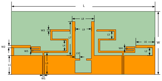
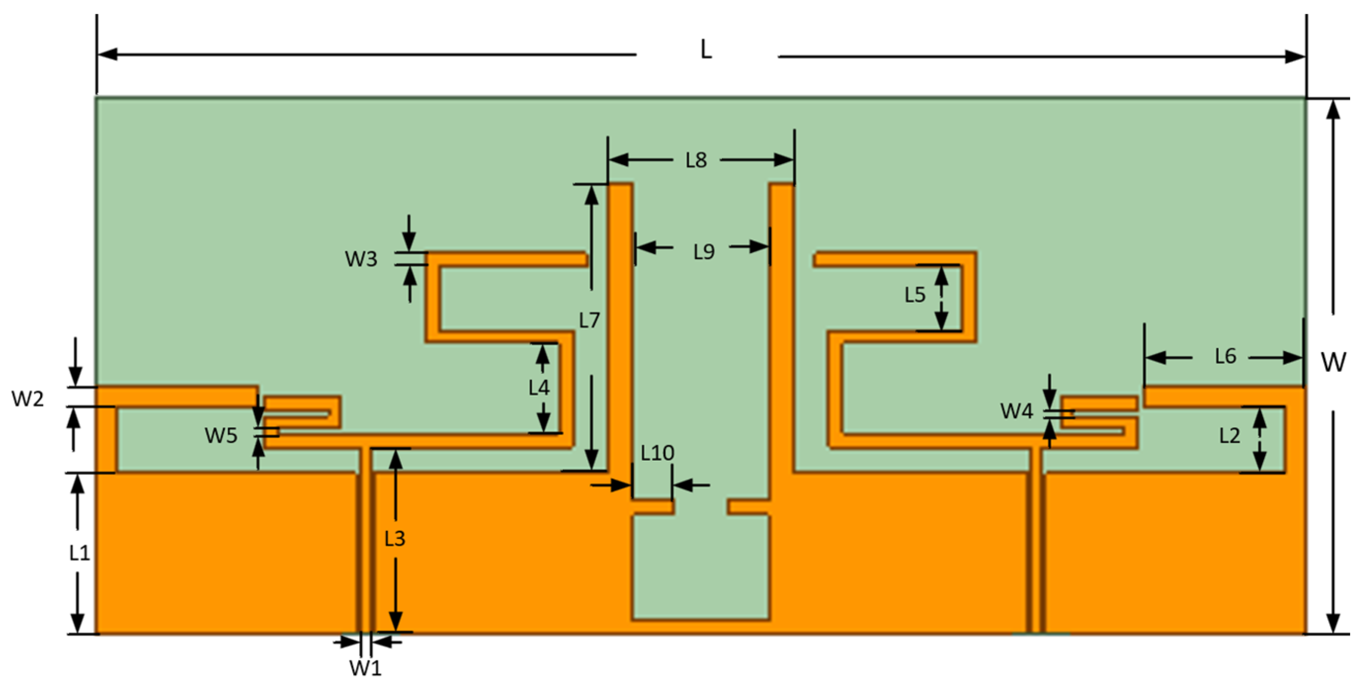
Figure 1 presents the overall structure of the proposed dual-band antenna with high port isolation. The design employs a mirror-symmetric layout comprising a dielectric substrate, a ground plane, two radiating elements, and two coupling units. The radiator, parasitic branches, and ground plane of the antenna are fabricated on the same side of the substrate, with a coplanar waveguide (CPW) feeding structure. The substrate is a flexible polyimide (PI) material, commonly used in flexible printed circuits (FPCs), with a relative permittivity (εᵣ) of 3.5 and a loss tangent (tan δ) of 0.008. Each radiating element integrates a feeder line with digitally profiled “2”-shaped and “5”-shaped radiating patches. To realize dual-band operation, an L-shaped structure and rectangular parasitic branches are loaded onto the coplanar ground plane.
Figure 1.
Antenna structure.
Furthermore, to enhance port isolation, U-shaped slots are etched into the ground plane, and two symmetrical parasitic branches are extended to provide decoupling. The antenna is fed by a 50 Ω coplanar waveguide (CPW). Following simulation and parametric optimization in Ansys HFSS, the final antenna dimensions are 90.0 mm × 40.0 mm × 0.1 mm. The corresponding structural parameters are detailed in Table 1.
Table 1.
Structural parameters of the antenna.
2.2. Antenna Structure Design Process
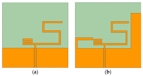
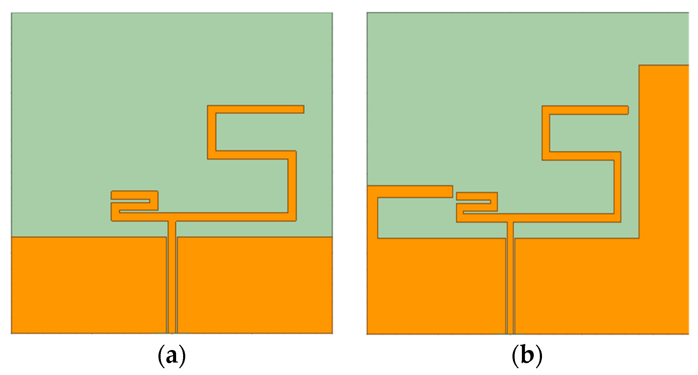
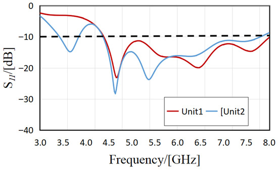
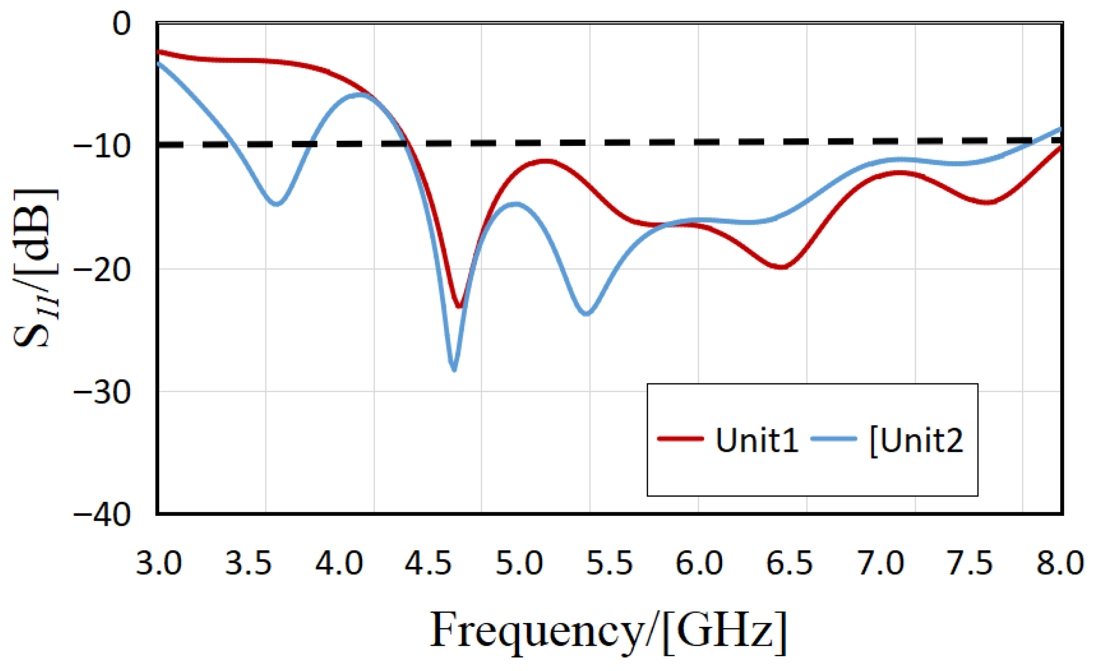
The antenna is fed by a coplanar waveguide (CPW), and the original modeling and electromagnetic simulation were completed using ANSYS Electronics Desktop (HFSS) 2021R1. The antenna unit (Unit1) adopts a monopole substructure composed of the combined geometric models of the digits “2” and “5”, as shown in Figure 2a. This digital contour is essentially a multi-segment bent planar path that extends the radiator’s current path while constrained by a limited substrate area, thereby meeting electrical length design requirements without increasing the planar footprint. Based on Unit 1, further structural optimization is performed to obtain the antenna unit (Unit 2). In this structure, L-shaped and rectangular composite parasitic stubs are loaded outward towards the ground plane to reconstruct the surface current distribution and excite new resonant modes, thereby achieving dual-frequency operating characteristics. As shown in Figure 3, the effective operating band of Unit1 is 4.38–8.00 GHz, while Unit2 spans two bands, 3.42–3.84 GHz and 4.37–7.80 GHz, effectively expanding the antenna’s operating bandwidth and improving its radiation performance.
Figure 2.
Evolution of antenna units: (a) Unit1, (b) Unit2.
Figure 3.
Comparison diagram of antenna unit S11.
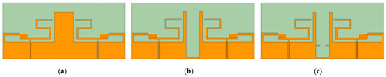
The two radiation units are symmetrically printed on a flexible circuit board (FPC) to form the initial design Antenna1, as shown in Figure 4a. The structure enables flexible substrate integration, but due to the close physical proximity of the two units and the continuous grounding plane, strong electromagnetic coupling occurs, affecting port isolation. To suppress mutual coupling between antenna units, the grounding plane of the antenna unit is optimized, and Antenna2 is constructed by etching the U-shaped slot, as shown in Figure 4b. The U-shaped slot can effectively block the direct propagation path of the surface current, reconstructing the surface current distribution, thereby reducing mutual interference between cells, concentrating energy in their respective radiation cells, and improving port isolation.
Figure 4.
Antenna structure design process: (a) Antenna 1; (b) Antenna 2; (c) Antenna 3.
To further enhance the decoupling effect, rectangular branches symmetrically arranged are introduced into the middle area of the U-shaped groove to form Antenna3. The structure is shown in Figure 4c. This branch is equivalent to introducing an additional resonant structure or a conductive path to regulate current distribution further and suppress coupling current. The combined design further improves the isolation between antenna elements while maintaining the structural characteristics of a thin, flexible antenna, thereby enhancing the isolation performance of a multi-antenna system.
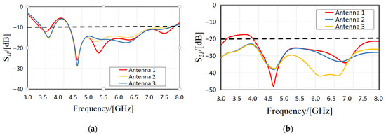
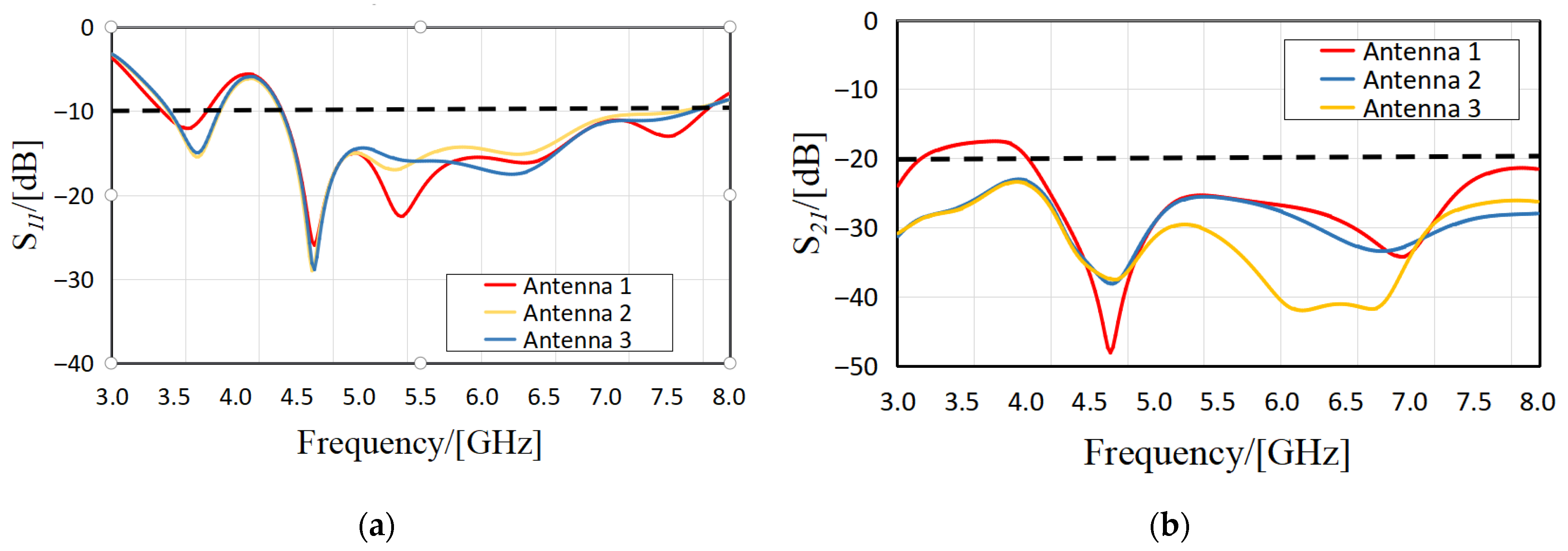
Figure 5 shows the simulation S parameters of three schemes (Antenna 1–3). Among them, S11 represents the port return loss, and the more negative its value, the better the matching. S21 indicates the isolation between ports. The negative value indicates the weaker mutual coupling. As shown in Figure 5a, impedance matching is essentially unaffected during the decoupling structure design and optimization, and the −10 dB impedance bandwidth of Antenna3 is 3.42–3.84 GHz and 4.37–7.80 GHz. It can be observed from Figure 5b that after the U-shaped slot is etched on the grounding plane by Antenna2, the overall low-frequency S21 is lower than −23.4 dB. Antenna3 further introduces symmetrical rectangular branches in the middle of the U-shaped slot to enhance high-frequency decoupling, thus improving the isolation at high-frequency resonance points. Compared with Antenna1, the isolation of Antenna3 increases from 17.55 dB to 25.12 dB at 3.7 GHz and from 27.88 dB to 41.54 dB at 6.28 GHz. Therefore, the proposed improved structure can effectively enhance the port isolation performance in the dual-band operating frequency band.
Figure 5.
Simulation S parameters of three antenna structures. (a) Return loss, (b) isolation.
The microstrip line width of the antenna is calculated according to the following formula:
As shown in Formulas (2)–(5), the power saving length and width of the microstrip branch are calculated according to the following formula [23]:
where “L” is the electrical length of the patch antenna, “W” is the microstrip line width, “Z0” is 50 Ω, “c” is the speed of light, “f” is the resonant frequency of the antenna, “r” is the relative dielectric constant [24], “ε” is the relative dielectric constant of the dielectric plate, and “h” is the height of the dielectric plate.
3. Results and Discussion
3.1. Simulation Results
The proposed antenna design takes the geometric contours of the digits “2” and “5” as the design prototype and maps them onto the planar geometry of the radiator. During the modeling and performance evaluation phase, full-wave simulation is performed using Ansoft HFSS (version 2021R1).
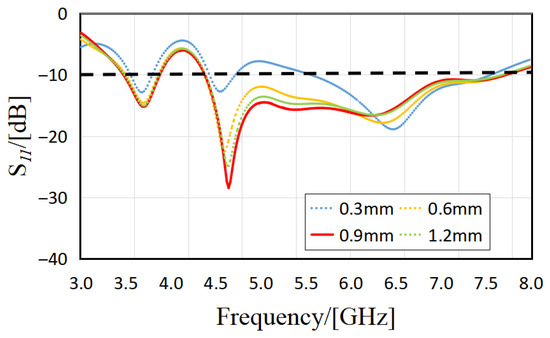
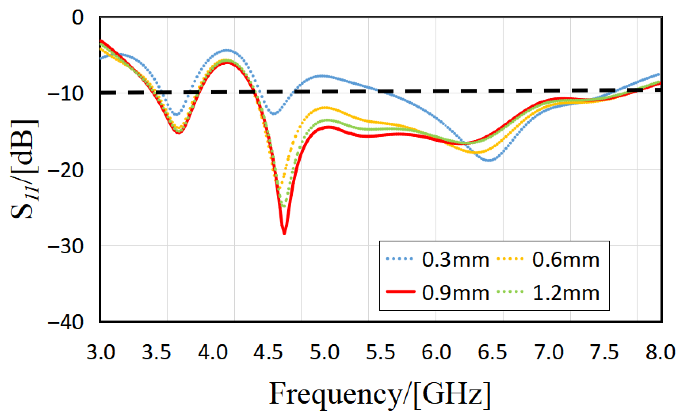
Parametric sweeps and optimizations are performed on the feed width (W1), the key dimensional parameter of the antenna, to evaluate its impact on impedance matching and operating bandwidth. Through simulation and optimization, a set of antenna parameters is determined that effectively covers the target communication frequency band. As shown in Figure 6, the trend of the antenna reflection coefficient (S11) indicates that W1 gradually increases from 0.3 mm to 1.2 mm. When W1 increases from 0.3 mm to 0.6 mm, the resonance frequency shifts to lower frequencies, and the −10 dB impedance bandwidth shifts downward as a whole, with noticeable changes. When W1 is in the range of 0.6 mm–0.9 mm, the S11 curve changes gently, and only moves down slightly with the increase in W1. When W1 further increases from 0.9 mm to 1.2 mm, the S11 curve shows a slight upward trend.
Figure 6.
Variation in S11 with different W1 lengths.
Considering the bandwidth coverage, impedance matching stability, and process feasibility, the feed width W1 = 0.9 mm was finally selected. At this value, the antenna exhibits good impedance matching over the target frequency band, meeting the application requirements of multi-band communication systems.
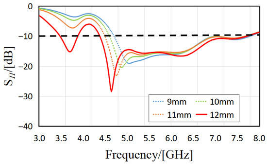
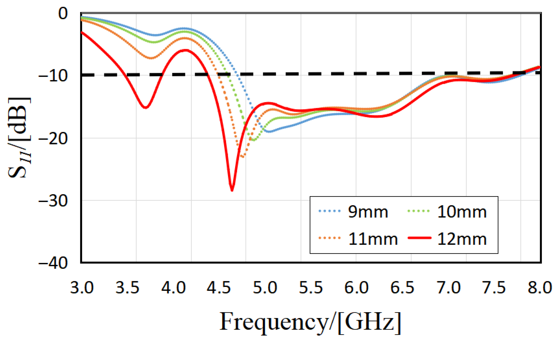
As shown in Figure 7, to evaluate the influence of the key parameter L3 of the antenna radiator on the operating characteristics, a parametric scanning analysis is performed over the range from 9 mm to 12 mm. The results show that as L3 increases, the resonant frequency of the S11 curve shifts to lower values, and S11 in the target frequency band shows a downward trend, indicating improved impedance matching performance. This trend is consistent with the inverse relationship between physical length and resonant frequency in antenna theory, indicating that the operating frequency band, especially the low-frequency edge, can be effectively adjusted by varying L3. After a comprehensive evaluation of performance indicators such as frequency coverage, bandwidth, and impedance matching, L3 = 12 mm is finally selected. This value can achieve wider bandwidth and lower return loss in the target operating frequency bands, such as 5G and Wi-Fi 7, and achieve a reasonable balance between frequency performance and structural compactness.
Figure 7.
Variation in S11 with different K2 lengths.
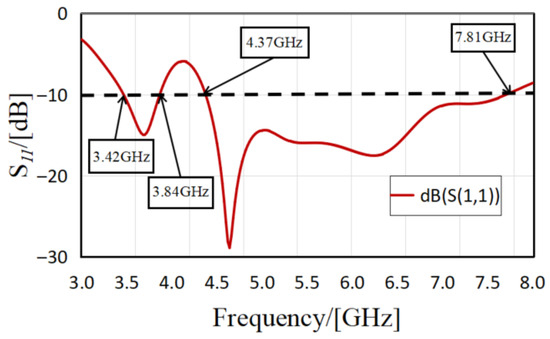
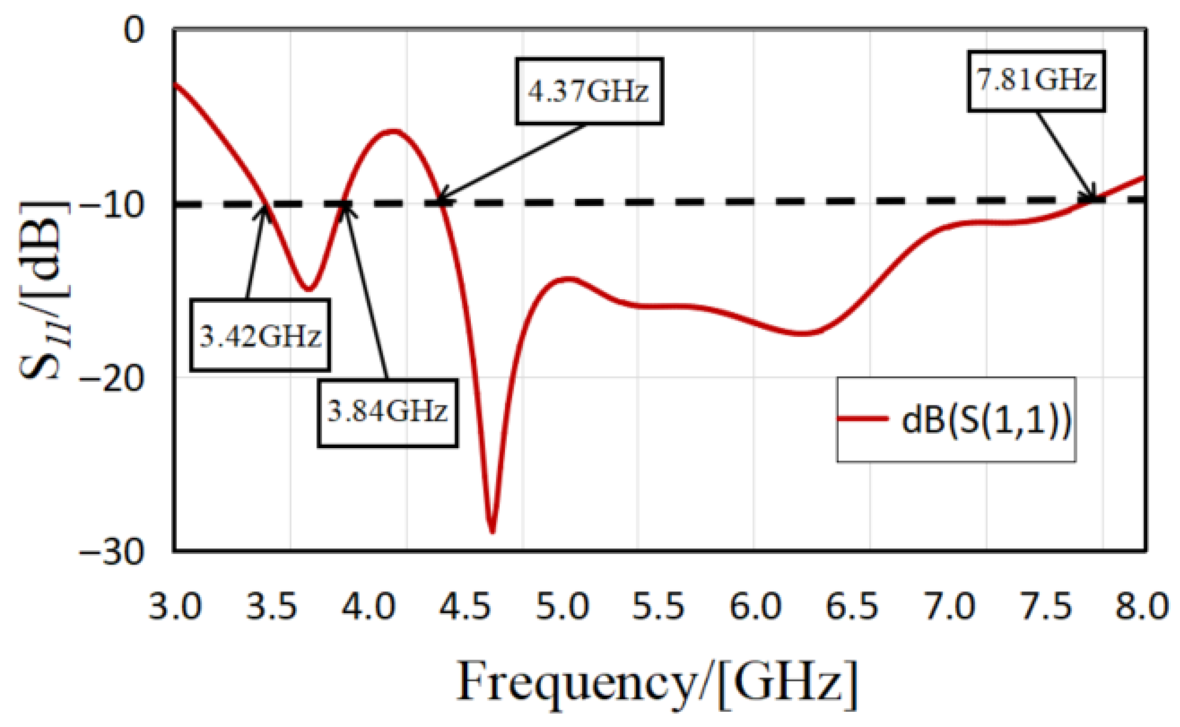
Figure 8 depicts the final return loss curves of the proposed MIMO antenna. The antenna exhibits two central resonant frequencies at 3.63 GHz and 6.09 GHz, with corresponding return losses of −14.17 dB and −17.28 dB, respectively. The operating bandwidths are 3.42–3.84 GHz and 4.37–7.80 GHz, with relative bandwidths of up to 11.6% and 56.4%, respectively.
Figure 8.
Return Loss Curve.
The frequency bands from antenna simulations cover communication bands such as 5G, WLAN, Wi-Fi 7, and the 6 GHz, as shown in Table 2.
Table 2.
Frequency bands covered by a dual-band MIMO antenna.
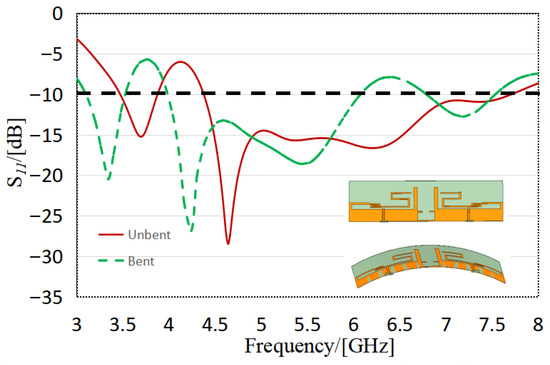
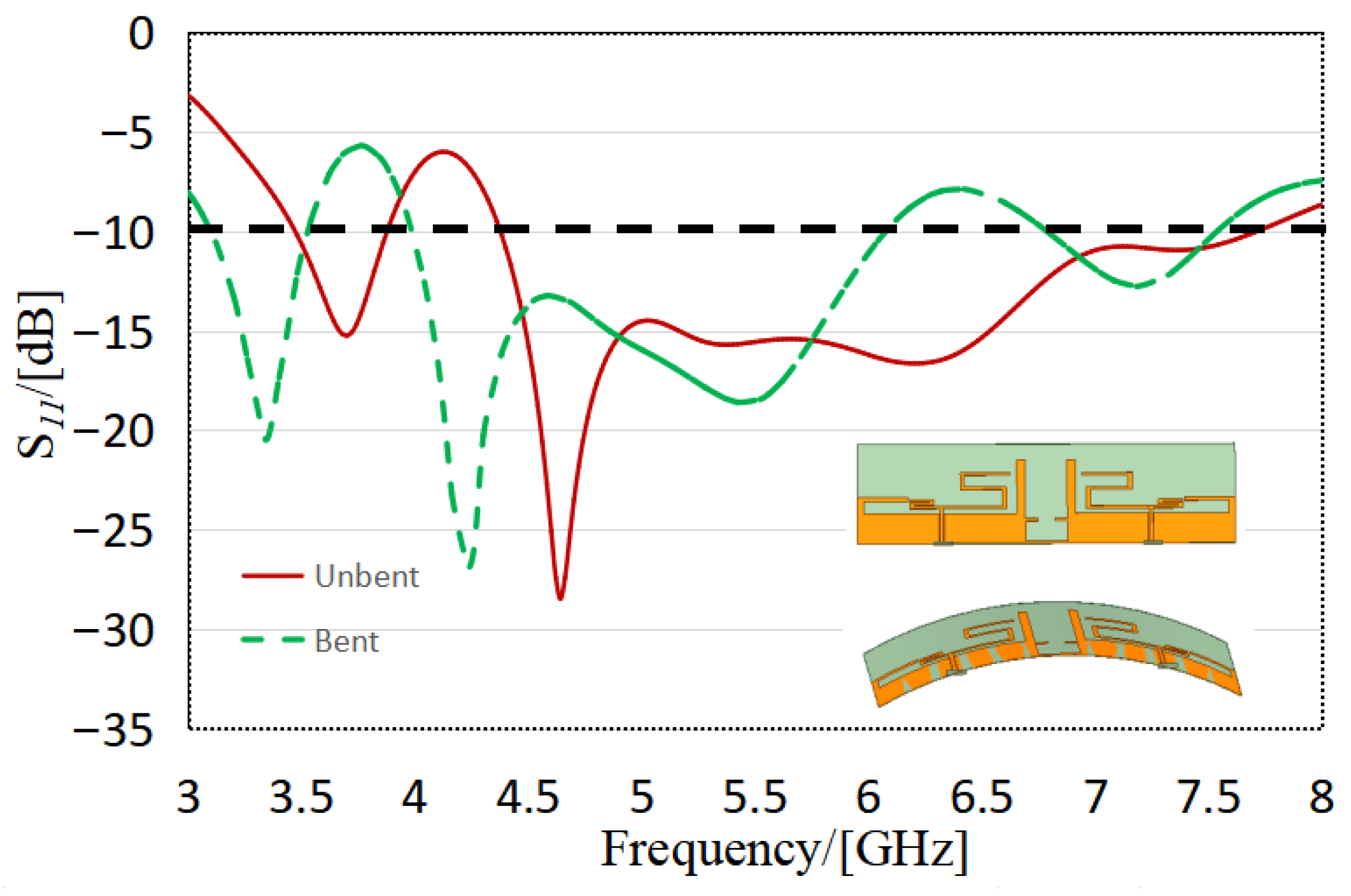
As illustrated in Figure 9, the frequency response of the flexible MIMO antenna changes when transitioning from a flat state to a bent state. In the low-frequency range, there is a slight shift in the resonant frequency, accompanied by a downward shift in the center frequency. The impedance bandwidth after bending is 3.10–3.53 GHz, which covers the key 5G n78 frequency band (3.4–3.6 GHz). It shows that the antenna has good tolerance for frequency drift caused by conformal bending and has stable low-frequency performance in practical wearable applications.
Figure 9.
Comparison of return loss between a non-bending antenna and a bending antenna.
In the high-frequency band, the continuous wideband covering 4.37–7.70 GHz in the planar state is split into two sub-bands under bending deformation, namely 3.99 GHz–6.08 GHz and 6.78–7.54 GHz, respectively. Despite the altered frequency band profile, the critical communication bands remain effectively covered. Specifically, the 5G n79 band (4.4–5.0 GHz) falls entirely within the first sub-band, while the core operating band of Wi-Fi 6E/Wi-Fi 7 (5.925–7.125 GHz) is fully covered jointly by the two sub-bands, guaranteeing full-band accessibility. The results verify that the antenna can preserve its core communication performance under bending deformation, exhibiting excellent structural adaptability and frequency stability.
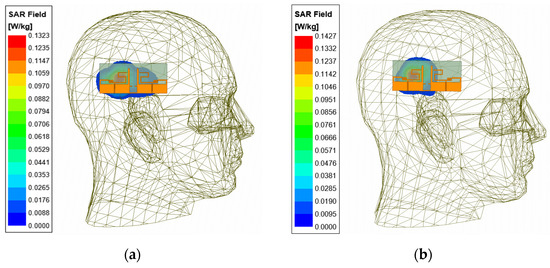
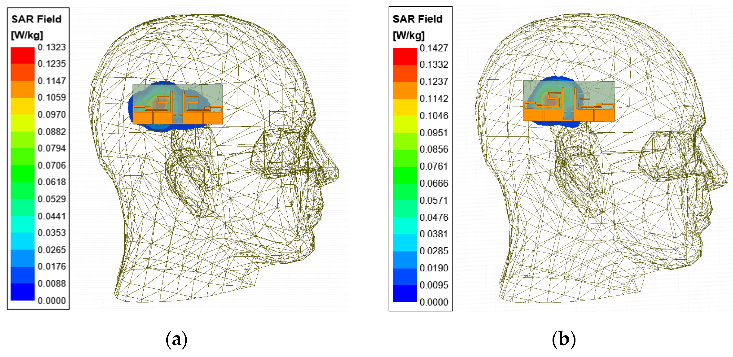
To evaluate the antenna’s electromagnetic radiation safety and operational performance in a near-body environment, this study modeled and simulated its Specific Absorption Rate (SAR) using Ansoft HFSS (version 2021R1) in accordance with the IEEE C95.1 standard [25]. The antenna’s SAR characteristics were investigated using a layered human equivalent model composed of skin, fat, muscle, and bone to replicate the electromagnetic response of real biological tissue [26]. In the simulations, the distance between the antenna and the head equivalent model was fixed at 1.5 cm. All SAR results were normalized to 1 W of input power and calculated using the 1 g tissue average method commonly employed in safety standards, enabling accurate simulation of electromagnetic energy absorption by wearable antennas. Figure 10 presents the SAR simulation results for the antenna in the head tissue model at two typical operating frequencies: 3.7 GHz and 4.6 GHz. At 1 W input power, the spatial peak 1 g averaged Specific Absorption Rate (SAR) is 0.1323 W/kg at 3.7 GHz and 0.1427 W/kg at 4.6 GHz. These values are well below the IEEE safety limits (average 1 g ≤ 1.6 W/kg) [25], indicating that the antenna meets international electromagnetic safety requirements for wearable health devices.
Figure 10.
SAR of antenna at (a) 3.7 GHz, (b) 4.6 GHz.
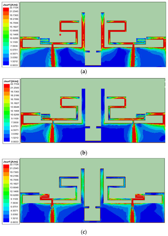
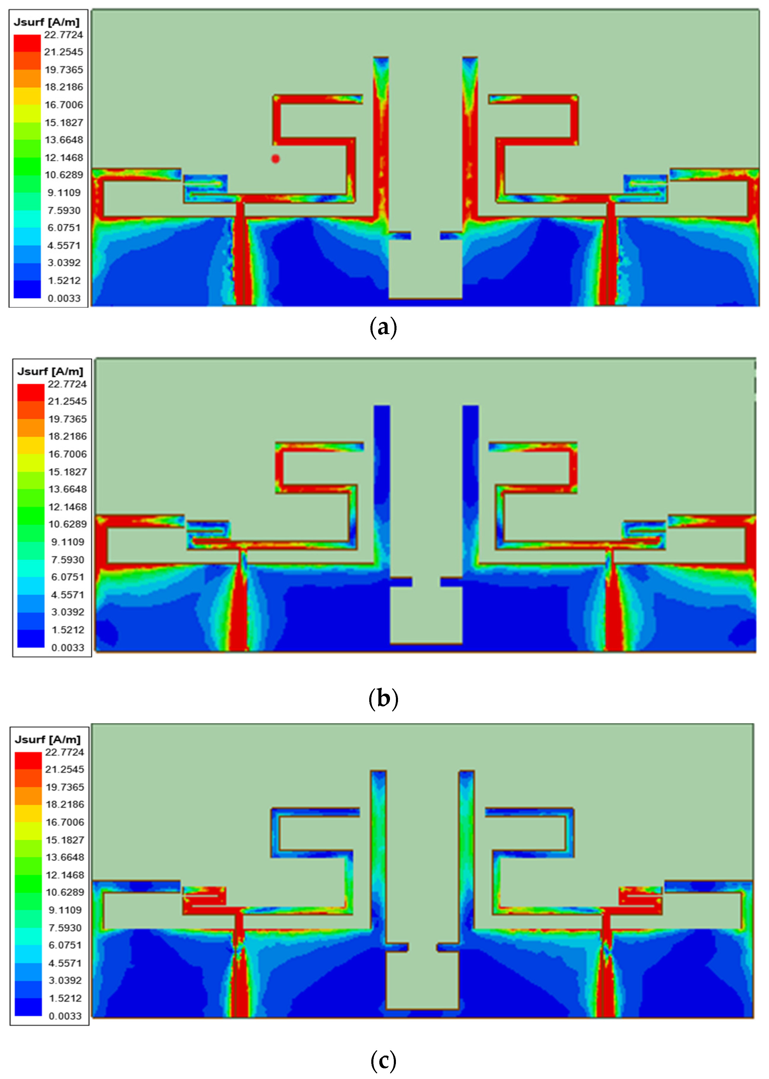
Figure 11 shows the surface current distribution of the MIMO antenna at three characteristic frequencies (3.7 GHz, 4.6 GHz, and 6.3 GHz). The figure shows differences in current concentration areas under different excitation frequencies, indicating that the dominant current path and radiation contribution structure differ across frequency bands.
Figure 11.
Surface current radiation diagram and vector distribution diagram: (a) 3.7 GHz, (b) 4.6 GHz, (c) 6.3 GHz.
In the 3.7 GHz low-frequency band shown in Figure 11a, the surface current is mainly concentrated on the feed structure, the digital “5”-shaped radiation branches, and the parasitic branches on both sides. The results show that the above structures primarily determine the resonance frequency, while parasitic branches broaden the low-frequency bandwidth and improve impedance matching. In the 4.6 GHz intermediate-frequency band shown in Figure 11b, the current distribution is more complex, with a main distribution across the feed structure, the “L”-shaped branches, the digital “5” branches, and the connection area between the digital “2” and “5”. It indicates that the resonant mode at this frequency involves multi-structure coupling and that the electromagnetic coupling between the “L”-shaped branch and the digital branch plays a key role in regulating the frequency response. In the 6.3 GHz high-frequency band shown in Figure 11c, the surface current is clearly concentrated in the feed area and the digital “2”-shaped radiation branch, indicating that the “2”-shaped structure mainly dominates the resonance at this frequency point. Its geometric dimensions significantly affect the radiation characteristics at this frequency. In conclusion, the current distribution diagram directly reveals the working mechanism and structural contribution of the antenna in different frequency bands, providing an essential physical basis for explaining its multi-band coverage characteristics.
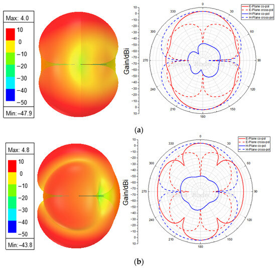
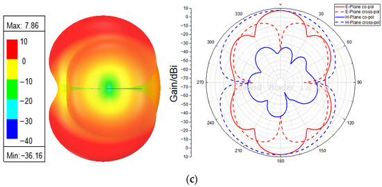
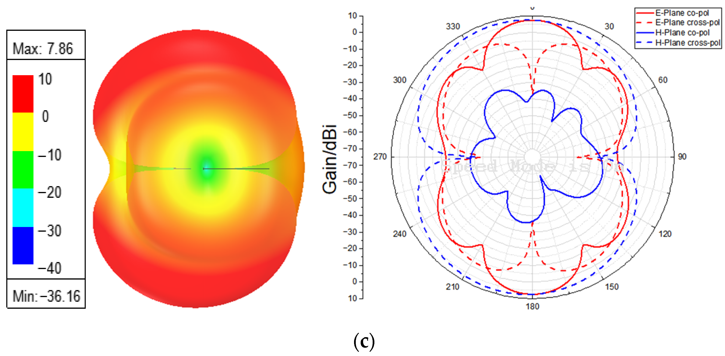
Figure 12 shows the simulated three-dimensional gain diagram and E/H cross-polarization characteristics of the antenna at 3.7 GHz, 4.6 GHz, and 6.3 GHz. At the center frequencies of 3.7 GHz, 4.6 GHz, and 6.3 GHz, the maximum gains of three-dimensional radiometric images are 4 dB, 4.8 dB, and 7.86 dB, respectively. The 2D polar-coordinate pattern on the right shows the radiation patterns of the electric field (E) and the magnetic field (H), where the solid line represents the main polarization component and the dotted line represents the cross-polarization component.
Figure 12.
Three-dimensional gain radiation mode and E-plane and H-plane radiation modes: (a) 3.7 GHz, (b) 4.6 GHz, (c) 7.86 GHz.
At the low-frequency point of 3.7 GHz, the primary radiation of the three-dimensional pattern is concentrated in the horizontal direction, in a flattened pattern. The E-plane and H-plane patterns are dominated by a single main lobe with low cross-polarization, indicating that the frequency point has good polarization purity. At the 4.6 GHz intermediate frequency point, the main lobe gain in the horizontal direction of the 3D pattern increases, and the gain depression in the vertical direction narrows slightly. The horizontal direction still dominates the overall radiation pattern. The E plane and H plane begin to show a multi-lobed structure. The main lobe gains increase synchronously, and the cross-polarization level rises slightly, remaining within an acceptable range, indicating that the antenna maintains good polarization isolation at this frequency. At 6.3 GHz, the 3D pattern shows a symmetrical, broad radiation distribution, and the gain depression in the vertical direction is further reduced, indicating that the antenna’s radiation efficiency and directivity in the entire space at this frequency are significantly improved. The E and H patterns show a clear four-lobe, symmetric structure, the main lobe pointing is stable, and the cross-polarization component level is slightly increased, reflecting the inherent characteristics of the antenna radiation mode at this frequency, and the polarization isolation meets the requirements of engineering applications.
3.2. Antenna Measurement Results
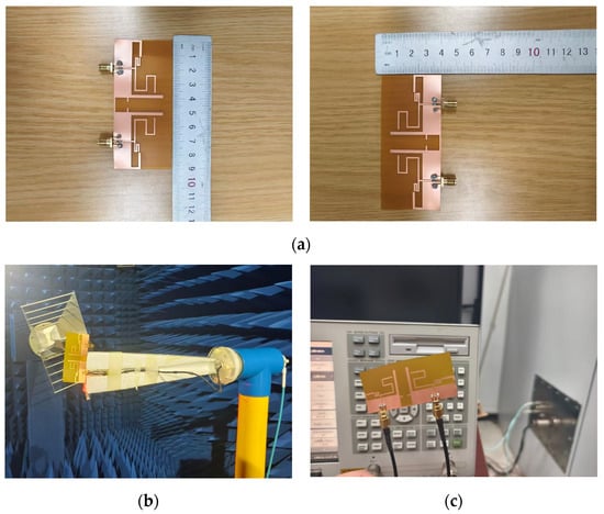
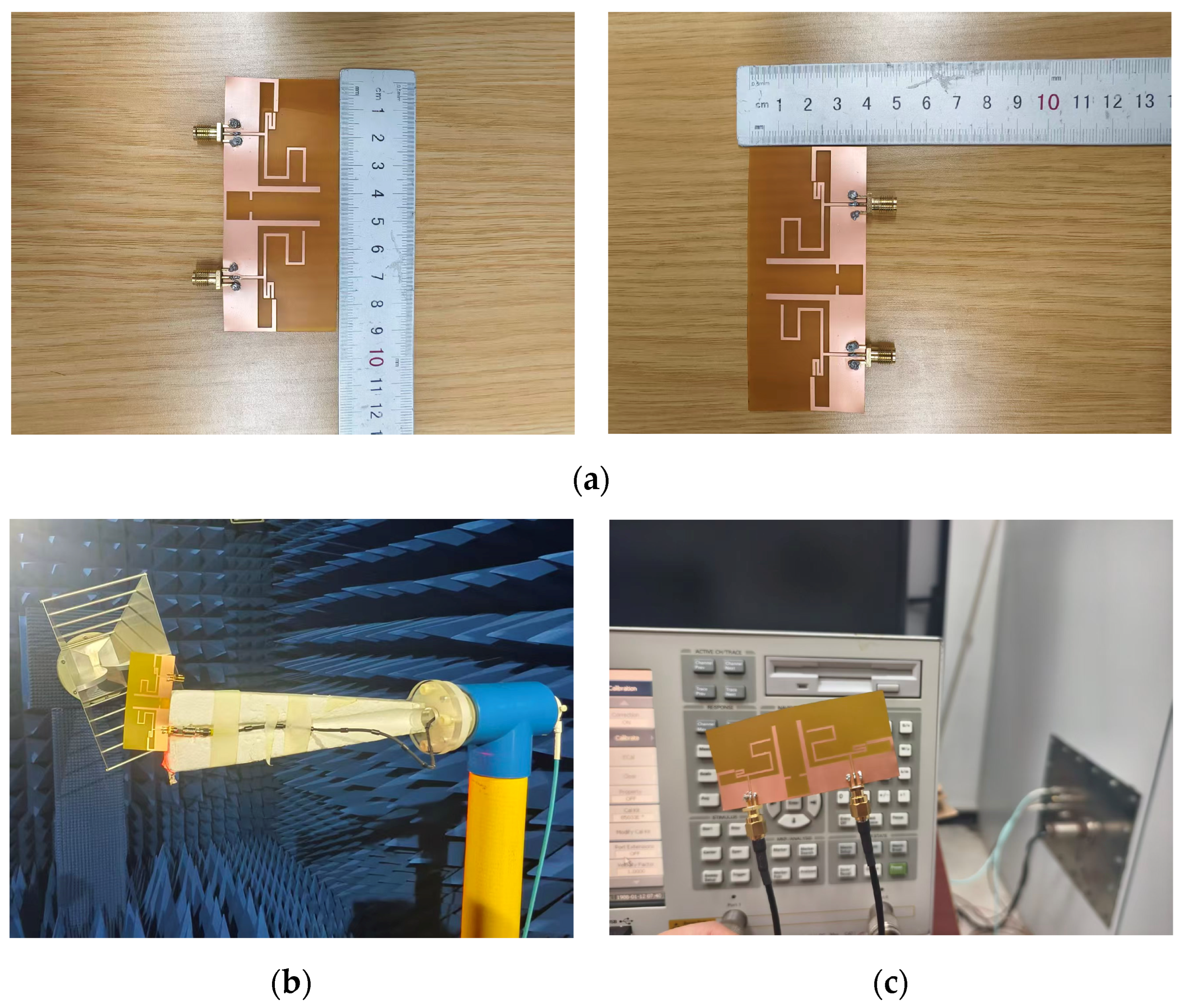
To verify the simulation results and the antenna’s actual performance, a prototype was fabricated and tested using a vector analyzer and a microwave anechoic chamber. The antenna prototype uses FPC polyimide (PI) as the dielectric substrate, with a dielectric constant εr = 3.5, a loss tangent tan δ = 0.008, an antenna size of 90 mm × 40 mm, and a thickness of 0.1 mm. Figure 13 shows the actual antenna and its test layout in the microwave anechoic chamber and uses a vector network analyzer to measure return loss and port isolation.
Figure 13.
Measurement antenna figure: (a) real antenna. (b) Testing the antenna in the anechoic chamber. (c) Using the vector analyzer to test the antenna.
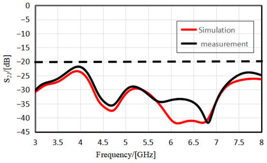
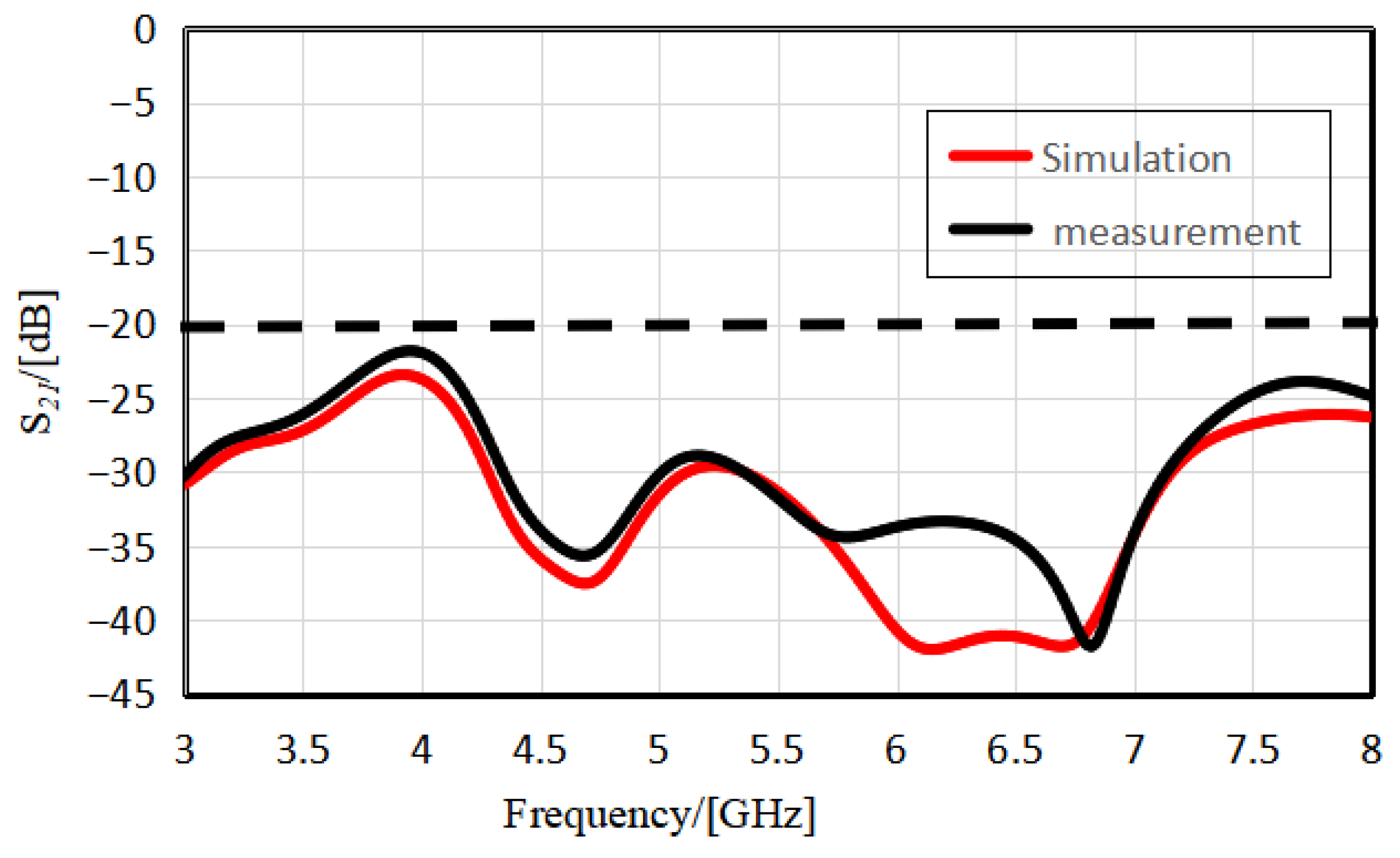
Figure 14 compares the simulated and measured S21 results for the proposed antenna in the 3–8 GHz frequency band. The results show that the variation trends in the simulated and measured curves are basically consistent. The S21 value is below −22 dB across the entire band, and the average isolation reaches approximately 40 dB in the 6–7 GHz band, fully demonstrating that the antenna exhibits excellent isolation performance in the target frequency band and effectively suppresses signal coupling between elements.
Figure 14.
Comparison between antenna simulation and measured S21.
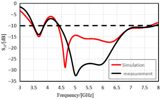
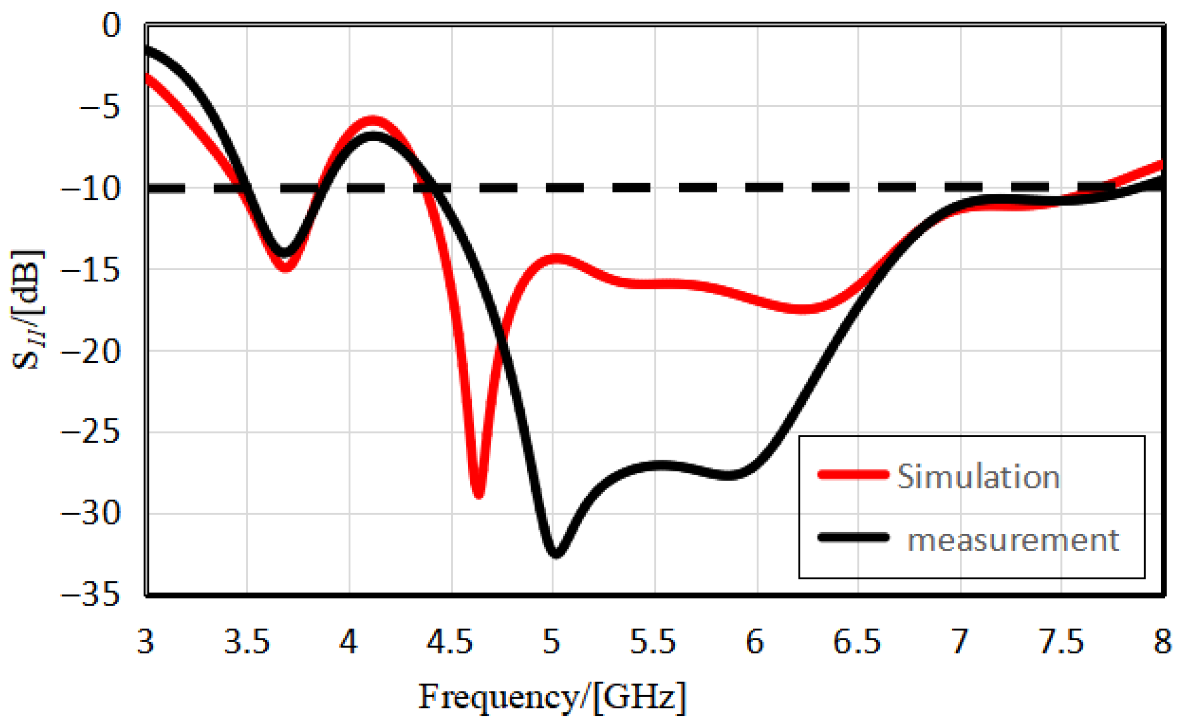
Figure 15 compares the simulated and measured results of the antenna reflection coefficient (S11) in the 3–8 GHz frequency band. The longitudinal axis is in dB, and the −10 dB dotted line is the key threshold for judging impedance matching performance. The results show that the overall change trend of the simulation curve (red) is consistent with that of the measured curve (black). In the 3.5–3.84 GHz and 4.42–7.66 GHz bands, both S11 values are below −10 dB, indicating good impedance matching. In the range of 4.5–5.5 GHz, both curves exhibit clear loss valleys, with the lowest measured value of about −32.5 dB and the lowest simulated value of about −28.8 dB, indicating strong reflection suppression in this frequency band. It can meet the demands of 5G communication systems for antenna impedance matching and operational stability.
Figure 15.
Comparison between antenna simulation and measured S11.
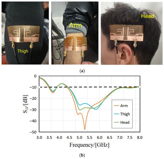
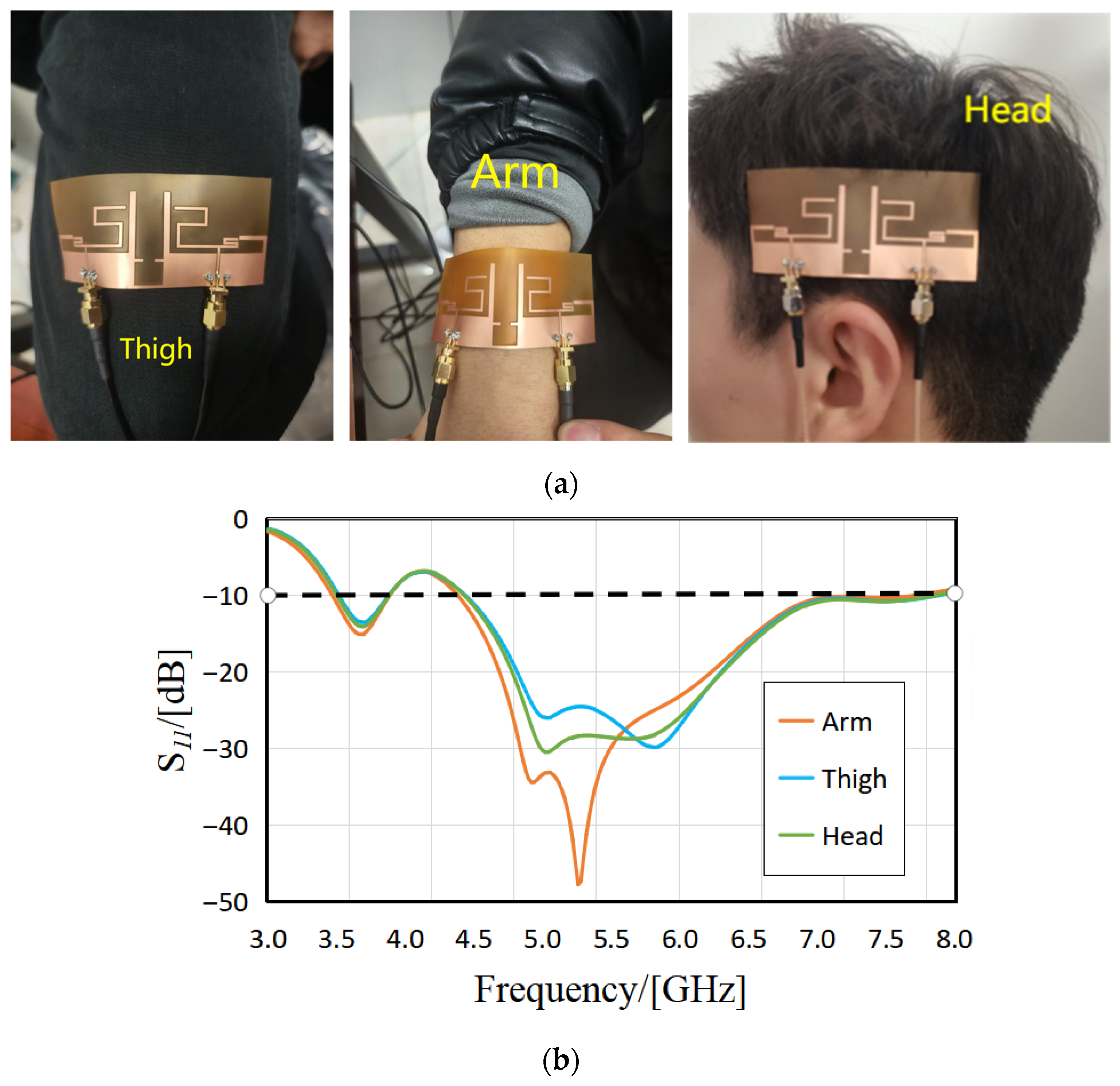
Figure 16 shows the return loss (S11) of an antenna in the 3.0–8.0 GHz frequency range when it is close to the arms, thighs, and head of the human body. The matching performance is optimal in the 4.0–6.5 GHz core frequency band, especially at 5.26 GHz. The S11 value is the lowest at −47.8 dB when it is close to the arms and can be maintained below −20 dB when it is close to the head and thighs. Although the performance slightly decreases in the 6.5–8.0 GHz high-frequency band, it still meets the requirements. The impact of different body parts on antenna matching mainly manifests as a change in matching depth, and the overall difference is not significant, indicating that the antenna maintains good stability across different body parts and is suitable for applications such as wearable and handheld terminals that are close to the body. Figure 16 shows the return loss (S11) of an antenna in the 3.0–8.0 GHz frequency range when it is close to the arms, thighs, and head of the human body. The matching performance is optimal in the 4.0–6.5 GHz core frequency band, especially at 5.26 GHz. The S11 value is the lowest at −47.8 dB when it is close to the arms, and can be maintained below −20 dB when it is close to the head and thighs. Although performance slightly decreases in the 6.5–8.0 GHz high-frequency band, it still meets the requirements. The impact of different body parts on antenna matching mainly manifests as a change in matching depth, and the overall difference is not significant, indicating that the antenna maintains good stability across different body parts and is suitable for applications such as wearable and handheld terminals that are close to the body.
Figure 16.
Comparison between antenna simulation and measured S11 at different positions: (a) antenna placement diagram, (b) S11 curve diagram.
The actual measuring antennas cover communication bands such as 5G, WLAN, Wi-Fi 7, and the 6 GHz band, as shown in Table 3.
Table 3.
The measured bandwidth and the frequency band covered by the antenna.
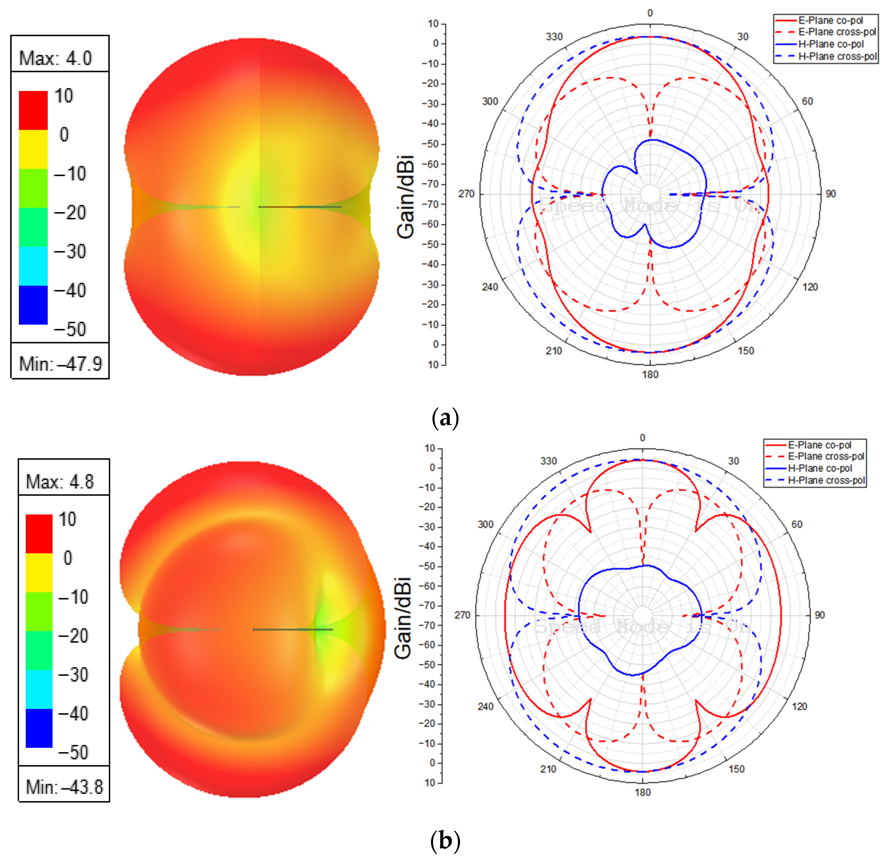
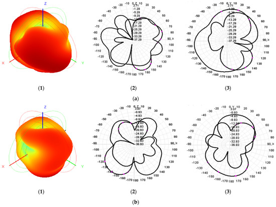
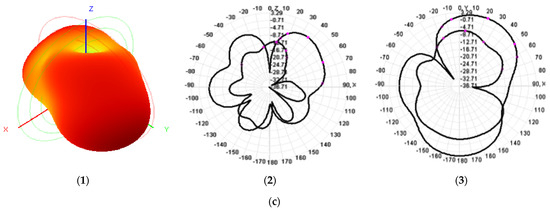
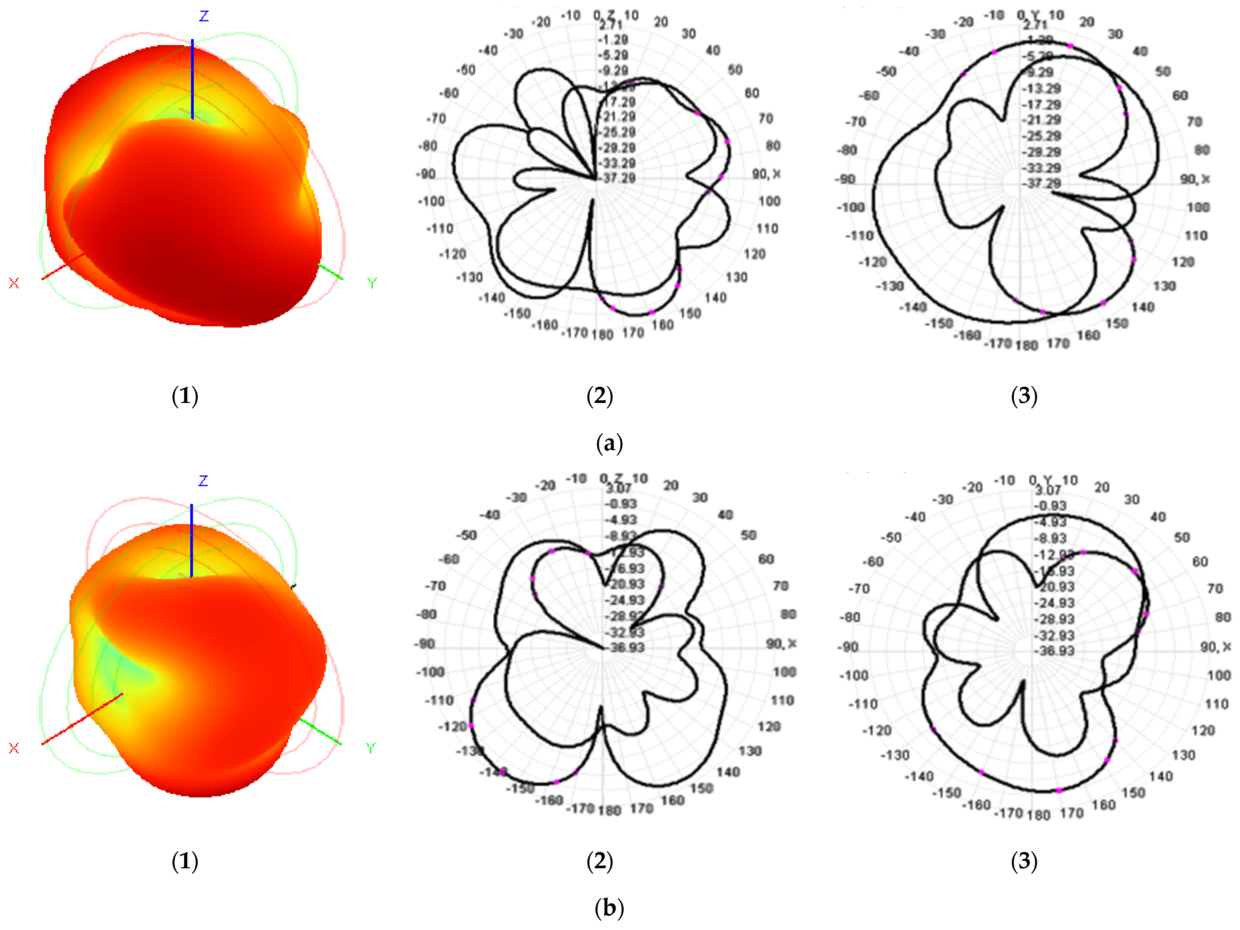
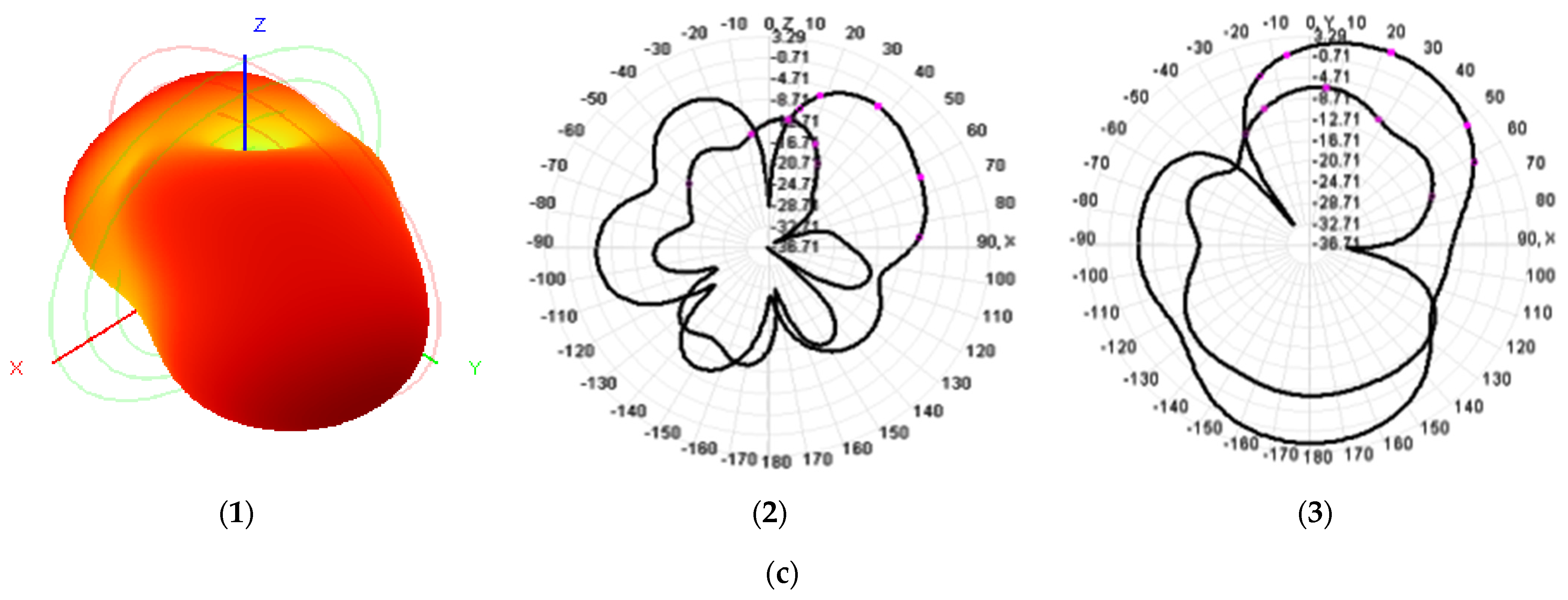
Figure 17(1) shows the three-dimensional far-field radiation patterns of the antenna at 3.7 GHz, 4.6 GHz, and 6.3 GHz, and the E-plane and H-plane cross-polarization at the corresponding frequencies are shown in Figure 17(2,3). As shown in Figure 16, the main lobe of the antenna radiation is relatively straightforward and exhibits some directionality. As the frequency increases, the side lobe appears in the three-dimensional radiation pattern, and the cross-polarization level increases. The measured antenna results differ slightly from the simulation results, due to processing and assembly tolerances, material parameter deviations, feed connectors, test cables, and the test environment.
Figure 17.
Measured 3D radiation mode and E/H plane cross-polarization: (1) 3D far-field radiation mode of antenna, (2) comparison diagram of E plane polarization and cross-polarizations, (3) comparison diagram of H plane polarizations and cross-polarizations, (a) 3.7 GHz, (b) 4.6 GHz, (c) 6.3 GHz.
The performance comparison results between the antenna designed in this paper and a similar antenna are shown in Table 4. Compared with existing similar studies, the flexible antenna proposed in this paper achieves a favorable synergistic balance across core performance dimensions. By adopting a flexible substrate, the proposed antenna enables better conformal fitting to the curved surfaces of wearable devices than rigid substrates used in Refs. [10,16,27,28]. Meanwhile, with a compact footprint of 90 × 40 mm2, it exhibits superior miniaturization performance over the counterparts reported in Refs. [10,19,20,21,27,28].
Table 4.
Comparison of the performance of the proposed antenna with that of the recent pioneering advanced-level antenna.
In terms of the collaborative design of bandwidth coverage and MIMO mutual coupling suppression, the antenna achieves dual operating bands of 3.5–3.88 GHz and 4.42–7.66 GHz, which cover the mainstream commercial 5G Sub-6 GHz frequency bands, and offers greater practicality than single-narrowband designs in Refs. [10,15,19,22]. Its port isolation reaches 23.4 dB, outperforming that of the same type of flexible antennas reported in Refs. [15,19,20,21,22]. The antenna achieves a peak gain of 7.86 dBi, surpassing all referenced antennas, both flexible and rigid. Meanwhile, it maintains the Specific Absorption Rate (SAR) at an extremely low level of 0.1323 W/kg, far below international electromagnetic safety limits. It avoids the problem of high gain but excessive SAR value reported in Ref. [15] and achieves a favorable balance between high radiation efficiency and low human electromagnetic exposure.
In summary, the antenna designed in this paper achieves favorable synergy and comprehensive balance among key performance metrics, including flexibility, miniaturization, operating bandwidth, isolation, radiation gain, and wearable safety. Its overall performance is suitable for helmet-mounted wearable devices.
4. Discussion
A dual-frequency flexible MIMO antenna is proposed in this study. The antenna employs a polyimide (PI) flexible substrate measuring 90.0 mm × 40.0 mm × 0.1 mm and features a compact structure. By optimizing the coplanar waveguide (CPW) feeding and radiating elements, the antenna achieves dual-band coverage spanning 3.42–3.84 GHz and 4.37–7.80 GHz. To enhance port isolation across a wide frequency band, a rectangular slot is introduced at the center of the ground plane, and symmetric rectangular parasitic structures are added to reconfigure the coupling current paths, ensuring the antenna maintains an isolation of at least 23.4 dB throughout the entire operating band. Furthermore, the antenna’s actual performance was tested. Bending experiments show that the antenna maintains good impedance matching and radiation performance under typical bending conditions. Specific Absorption Rate (SAR) analysis shows that, with input power normalized to 1 W, the antenna’s 1 g averaged peak SAR values at 3.7 GHz and 4.6 GHz are 0.1323 W/kg and 0.1427 W/kg, respectively—well below international safety standards and meeting human safety requirements for wearable devices.
In conclusion, the antenna structure proposed in this paper achieves a reasonable trade-off among miniaturization, high isolation, dual-band wideband, and wearability, providing a viable antenna design approach for 5G/6G helmet-type devices.
Author Contributions
Conceptualization, Z.Y. and Y.X.; methodology, X.W.; software, Y.X.; validation, Y.X., F.W. and Y.C.; formal analysis, Y.X.; investigation, Y.N.; resources, X.K.; data curation, Z.T.; writing—original draft preparation, Y.X.; writing—review and editing, Z.T.; supervision, X.R.; project administration, X.R. All authors have read and agreed to the published version of the manuscript.
Funding
This work was supported in part by the Key Research and Development Program of Hebei Province, grant number 23375402D, in part by the Innovation Capability Training Program for Graduate Students of Hebei Province, grant number CXZZSS2025140, and in part by the Fundamental Research Funds for the Central Universities under Grant ZY20250108.
Institutional Review Board Statement
Our study does not involve any human or animal subjects. The experiments described in the text primarily aim to demonstrate that when an antenna is placed near different parts of the human body and undergoes different deformations, there is no significant difference in its return loss. Therefore, IRB approval may not be required.
Data Availability Statement
The data presented in this study are available upon request from the corresponding author.
Conflicts of Interest
The authors declare no conflicts of interest.
Abbreviations
The following abbreviations are used in this manuscript:
| MIMO | Multiple-Input Multiple-Output |
| CPW | Coplanar Waveguide |
| SAR | Specific Absorption Rate |
| BCIs | Brain–Computer Interfaces |
| Ref. | Reference |
| Refs. | References |
References
- Wang, W.; Fang, Z.; Tang, K.; Wang, X.; Shu, Z.; Zhao, Z.; Zheng, Y. Wideband Gain Enhancement of MIMO Antenna and Its Application in FMCW Radar Sensor Integrated with CMOS-Based Transceiver Chip for Human Respiratory Monitoring. IEEE Trans. Antennas Propag. 2023, 71, 318–329. [Google Scholar] [CrossRef] [Scilit]
- Alibakhshikenari, M.; Babaeian, F.; Virdee, B.S.; Aissa, S.; Azpilicueta, L.; See, C.H.; Althuwayb, A.A.; Huynen, I.; Abd-Alhameed, R.A.; Falcone, F.; et al. A Comprehensive Survey on ‘Various Decoupling Mechanisms with Focus on Metamaterial and Metasurface Principles Applicable to SAR and MIMO Antenna Systems’. IEEE Access 2020, 8, 192965–193004. [Google Scholar] [CrossRef] [Scilit]
- Blanch, S.; Romeu, J.; Corbella, I. Exact representation of antenna system diversity performance from input parameter description. Electron. Lett. 2003, 39, 705–707. [Google Scholar] [CrossRef] [Scilit]
- Huang, J.; Dong, G.; Cai, J.; Li, H.; Liu, G. A quad-port dual-band MIMO antenna array for 5G smartphone applications. Electronics 2021, 10, 542. [Google Scholar] [CrossRef] [Scilit]
- Zhang, J.; Du, C.; Wang, R. Design of a four-port flexible UWB-MIMO antenna with high isolation for wearable and IoT applications. Micromachines 2022, 13, 2141. [Google Scholar] [CrossRef] [Scilit]
- Zhang, B.; Jornet, J.M.; Akyildiz, I.F.; Wu, Z.P. Mutual coupling reduction for ultra-dense multi-band plasmonic nano-antenna arrays using graphene-based frequency selective surface. IEEE Access 2019, 7, 33214–33225. [Google Scholar] [CrossRef] [Scilit]
- Khan, A.; Bashir, S.; Ghafoor, S.; Qureshi, K.K. Mutual coupling reduction using ground stub and EBG in a compact wideband MIMO antenna. IEEE Access 2021, 99, 40972–40979. [Google Scholar] [CrossRef] [Scilit]
- Sufian, M.A.; Hussain, N.; Abbas, A.; Lee, J.; Park, S.G.; Kim, N. Mutual coupling reduction of a circularly polarised MIMO antenna using parasitic elements and DGS for V2X communications. IEEE Access 2022, 10, 56388–56400. [Google Scholar] [CrossRef] [Scilit]
- Nadeem, I.; Choi, D.Y. Study on mutual coupling reduction technique for MIMO antennas. IEEE Access 2019, 7, 563–586. [Google Scholar] [CrossRef] [Scilit]
- Fang, Y.; Jia, Y.; Zhu, J.-Q.; Liu, Y.; An, J. Self-Decoupling, Shared-Aperture, Eight-Antenna MIMO Array with MIMO-SAR Reduction. IEEE Trans. Antennas Propag. 2024, 72, 1905–1910. [Google Scholar] [CrossRef] [Scilit]
- Raheja, D.K.; Kumar, S.; Kanaujia, B.K. Compact quasielliptical-self-complementary four-port super-wideband MIMO antenna with dual band elimination characteristics. AEU Int. J. Electron. Commun. 2020, 114, 153001. [Google Scholar] [CrossRef] [Scilit]
- Çelenk, E.; Tokan, N.T. All-Textile On-Body Antenna for Military Applications. IEEE Antennas Wirel. Propag. Lett. 2022, 21, 1065–1069. [Google Scholar] [CrossRef] [Scilit]
- Wu, R.; Dong, J.; Wang, M. Wearable polarisation conversion metasurface MIMO antenna for biomedical applications in 5 GHz WBAN. Biosensors 2023, 13, 73. [Google Scholar] [CrossRef] [Scilit] [PubMed]
- Samal, P.B.; Chen, S.J.; Fumeaux, C. Wearable textile multi-band antenna for WBAN applications. IEEE Trans. Antennas Propag. 2023, 71, 1391–1402. [Google Scholar] [CrossRef] [Scilit]
- Pradeep, P.; Basha, M.M.; Gundala, S.; Syed, J. Development of wearable textile MIMO antenna for sub-6 GHz band new radio 5G applications. Micromachines 2024, 15, 651. [Google Scholar] [CrossRef] [Scilit]
- Khan, R.; Sethi, W.T.; Malik, W.A.; Jan, L.; Tahseen, M.M.; Almuhlafi, A.M.; Himdi, M. Enhancing gain and isolation of a quad-element MIMO antenna array design for 5G sub-6 GHz applications assisted with characteristic mode analysis. Sci. Rep. 2024, 14, 11111. [Google Scholar] [CrossRef] [Scilit]
- Arya, A.K.; Kim, T.; Kim, H.; Oh, J.; Kim, J.; Moon, D.; Kim, S. Compact BLE antenna with a modified PIFA configuration for wearable EMG monitor. IEEE Sens. J. 2023, 23, 17648–17655. [Google Scholar] [CrossRef] [Scilit]
- Althuwayb, A.A.; Alibakhshikenari, M.; Virdee, B.S.; Rashid, N.; Kaaniche, K.; Ben Atitallah, A.; Armghan, A.; Elhamrawy, O.I.; See, C.H.; Falcone, F. Metasurface-inspired flexible wearable MIMO antenna array for wireless body area network applications and biomedical telemetry devices. IEEE Access 2023, 11, 1039–1056. [Google Scholar] [CrossRef] [Scilit]
- John, D.M.; Vincent, S.; Pathan, S.; Shinde, K.D.; Supreetha, B.S.; Ali, T. Eight-element flexible MIMO antenna based on characteristics mode theory with enhanced channel capacity for sub 6 GHz 5G communications. Results Eng. 2025, 25, 104208. [Google Scholar] [CrossRef] [Scilit]
- Kumar, D.; Sharma, D.; Tiwari, R.N.; Khan, I.A.; Kumar, P. Multi-band flexible MIMO antenna for NB-IoT/ISM/5 G and wearable applications. Results Eng. 2025, 27, 106088. [Google Scholar] [CrossRef] [Scilit]
- Jayant, S.; Srivastava, G.; Kumar, S. Quad-Port UWB MIMO footwear antenna for wearable applications. IEEE Trans. Antennas Propag. 2022, 70, 7905–7913. [Google Scholar] [CrossRef] [Scilit]
- Baudh, R.K.; Sahu, S.; Parihar, M.S.; Dinesh Kumar, V. A Wideband Circularly Polarized All Textile on Body Antenna for Defense Applications. IEEE Trans. Circuits Syst. II Express Briefs 2024, 71, 567–571. [Google Scholar] [CrossRef] [Scilit]
- Yu, Z.; Wang, F.; Zhang, R.; Niu, R.; Chang, Y.; Ran, X.; Sun, R.; Zhang, G.; Lu, Z. A Flexible Multi-Band Antenna with a Spider Web-like Structure for 4G/5G/GPS/WIMAX/WLAN Applications. Electronics 2025, 14, 253. [Google Scholar] [CrossRef] [Scilit]
- Yu, Z.; Chang, Y.; Niu, R.; Zhang, R.; Wang, F.; Sun, R.; Zhang, G.; Ran, X. A New Koch and Hexagonal Fractal Combined Circular Structure Antenna for 4G/5G/WLAN Applications. Electronics 2025, 14, 237. [Google Scholar] [CrossRef] [Scilit]
- IC95.1-2019-IEEE; Standard for Safety Levels with Respect to Human Exposure to Electric, Magnetic, and Electromagnetic Fields, 0 Hz to 300 GHz. IEEE: Piscataway, NJ, USA, 2019.
- Gour, S.; Rathi, A.; Yadav, A.; Yadav, D.; Goyal, A.K. A compact H-shaped dual-band and dual-polarised wearable antenna design for ON and OFF body-centric communications. Results Eng. 2025, 28, 107281. [Google Scholar] [CrossRef] [Scilit]
- Kiani, S.H.; Savci, H.S.; Abubakar, H.S.; Parchin, N.O.; Rimli, H.; Hakim, B. Eight-element MIMO antenna array with tri-band response for modern smartphones. IEEE Access 2023, 11, 44244–44253. [Google Scholar]
- Rai, A.K.; Jaiswal, R.K.; Kumari, K.; Srivastava, K.V.; Sim, C.-Y.-D. Wideband monopole eight-element MIMO antenna for 5G mobile terminal. IEEE Access 2023, 11, 689–696. [Google Scholar] [CrossRef] [Scilit]


Disclaimer/Publisher’s Note: The statements, opinions and data contained in all publications are solely those of the individual author(s) and contributor(s) and not of MDPI and/or the editor(s). MDPI and/or the editor(s) disclaim responsibility for any injury to people or property resulting from any ideas, methods, instructions or products referred to in the content. |
© 2026 by the authors. Licensee MDPI, Basel, Switzerland. This article is an open access article distributed under the terms and conditions of the Creative Commons Attribution (CC BY) license.