


Abstract
In this paper, a novel scheme is introduced that combines a traveling wave tube (TWT) with a metasurface to generate high-power E-band vortex electromagnetic waves. The TE10 mode electromagnetic wave emitted by the TWT is initially converted into a plane wave via a horn antenna and subsequently transformed into a vortex electromagnetic wave by the metasurface. The metasurface is designed and simulated, and the results show that this approach can convert the TE10 mode from the TWT into vortex electromagnetic waves with a specific topological charge of within the 71–76 GHz frequency range, achieving a remarkable mode purity of up to 97%. The experiment at 73.5 GHz was successfully carried out, generating vortex electromagnetic waves with the designated topological charge of using this method. Although the experimentally measured mode purity was limited to 30.6%, this outcome confirms the effectiveness of the proposed method.
1. Introduction
In 1992, Allen et al. first determined that possessing a transverse helical phase structure is a necessary and sufficient condition for electromagnetic waves to have orbital angular momentum (OAM) [1]. This special wave, carrying OAM with a helical phase structure known as a vortex electromagnetic wave, has since garnered significant attention in both basic research and applications, especially in high-data-rate communication, including generating OAM-carrying vortex beams using a uniform circular array antenna in radio science [2], the transmission of statistical-state OAM waves in free space [3], the realization of OAM multiplexing communication over 10 m [4], and high-capacity transmission experiments of 200 Gbit/s using dual-polarized OAM-MIMO multiplexing with uniform circular array antenna technology in the 28 GHz band [5]. The ways to directly generate vortex waves include phased antenna arrays [6], microstrip antennas [7], dielectric rod antennas [8], and metal resonant cavities. Phase-modulation methods involve spiral phase plates [9], transmission gratings [10], spiral parabolic antennas [11], stepped reflectors, and metasurfaces [12]. In particular, metasurfaces have become a powerful platform for generating vortex waves due to their ability to manipulate the phase front with subwavelength resolution. Recent research progress has demonstrated the generation of complex vortex beams, including perfect vortex beams and multi-channel vortex beams, particularly in the optical band [13]. Furthermore, space–time–coding digital metasurfaces have been extensively studied for wireless communication applications, enabling functions such as frequency conversion, beam steering, and multiplexing [14]. Additionally, broadband dual-mode vortex waves have been realized using Pancharatnam–Berry phase metasurfaces, achieving a relative bandwidth of 54.55% [15]. Moreover, spin-decoupled multichannel metasurfaces have been demonstrated to enable wavevector and frequency multiplexing, achieving four-channel wavefront control with up to ten channel beams [16]. Even more sophisticated control techniques, such as interference-assisted kaleidoscopic meta-plexers for arbitrary spin-wavefront manipulation, have also been proposed, realizing independent spin-selective wavefront control and frequency-switchable vortex beams [17]. Furthermore, significant progress has been made in generating high-power vortex waves in the terahertz and optical bands—for example, kilowatt-level terahertz vortex beams achieved using gyrotrons [18], intense terahertz vortices with sub-GV/m field strengths generated via laser–plasma channels [19], and relativistic-intensity vortex lasers for plasma interactions [20]. However, these methods typically rely on bulky and complex systems (such as gyrotrons or high-power lasers), making them difficult to integrate into compact communication or radar front ends. In the millimeter-wave band, particularly the E-band, research on vortex waves remains very limited and has mainly focused on low-power communication scenarios. Moreover, most metasurface-based vortex wave generators operate in the optical band or at lower microwave frequencies, with experimental demonstrations in the E-band millimeter-wave range being particularly rare. High-power vortex waves hold great potential for applications in radar, electronic countermeasures, inter-base communications, satellite-to-ground links, and industrial micromachining, yet this area remains largely unexplored.
To address this gap, this paper proposes a radiation system driven by a traveling wave tube and a transmissive metasurface. By combining high-power capability with a planar, easy-to-fabricate structure, this system offers a more compact and practical solution for generating high-power vortex waves in the E-band, with promising applications in future wireless communication and radar systems. Experimental results demonstrate that the system successfully generates vortex electromagnetic waves with a topological charge of within the 71–76 GHz communication band, validating the feasibility of the proposed scheme.
2. The Metasurface and the System Design
The system connects the output port of the traveling wave tube to a horn antenna, with a metasurface placed 60 mm behind the horn antenna to generate high-power vortex electromagnetic waves carrying a topological charge of . A 71–76 GHz all-metal folded waveguide traveling wave tube is employed in this work. Under operating conditions of 13.1 kV and 85 mA, it delivers a continuous wave output power of 40 W with a total efficiency of 17.6%.
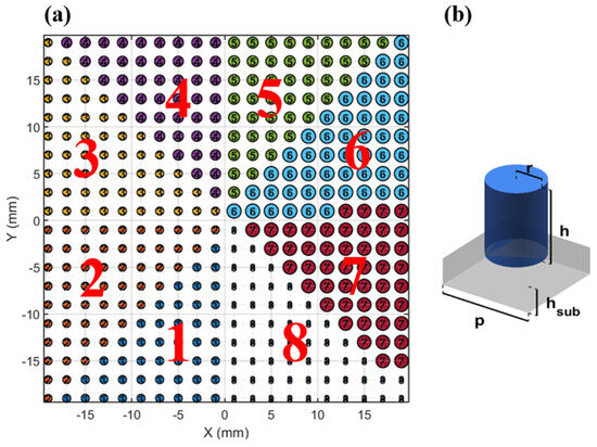
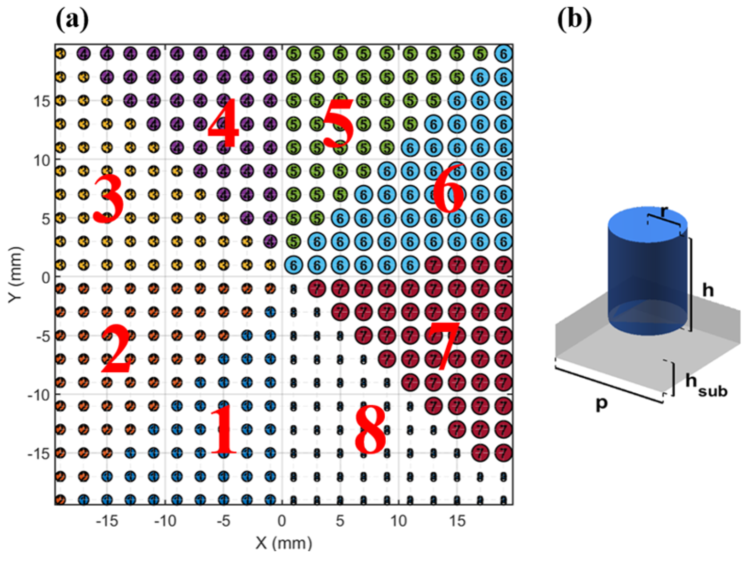
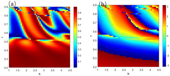
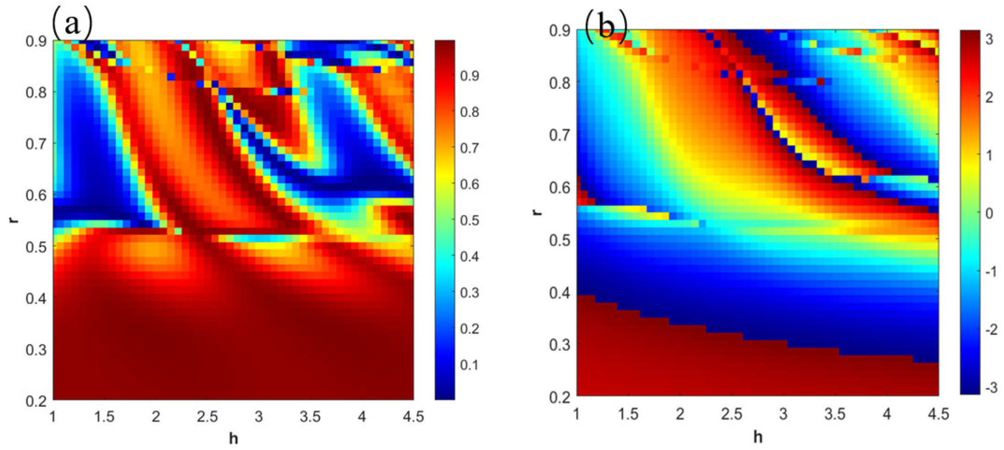
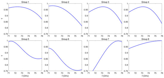
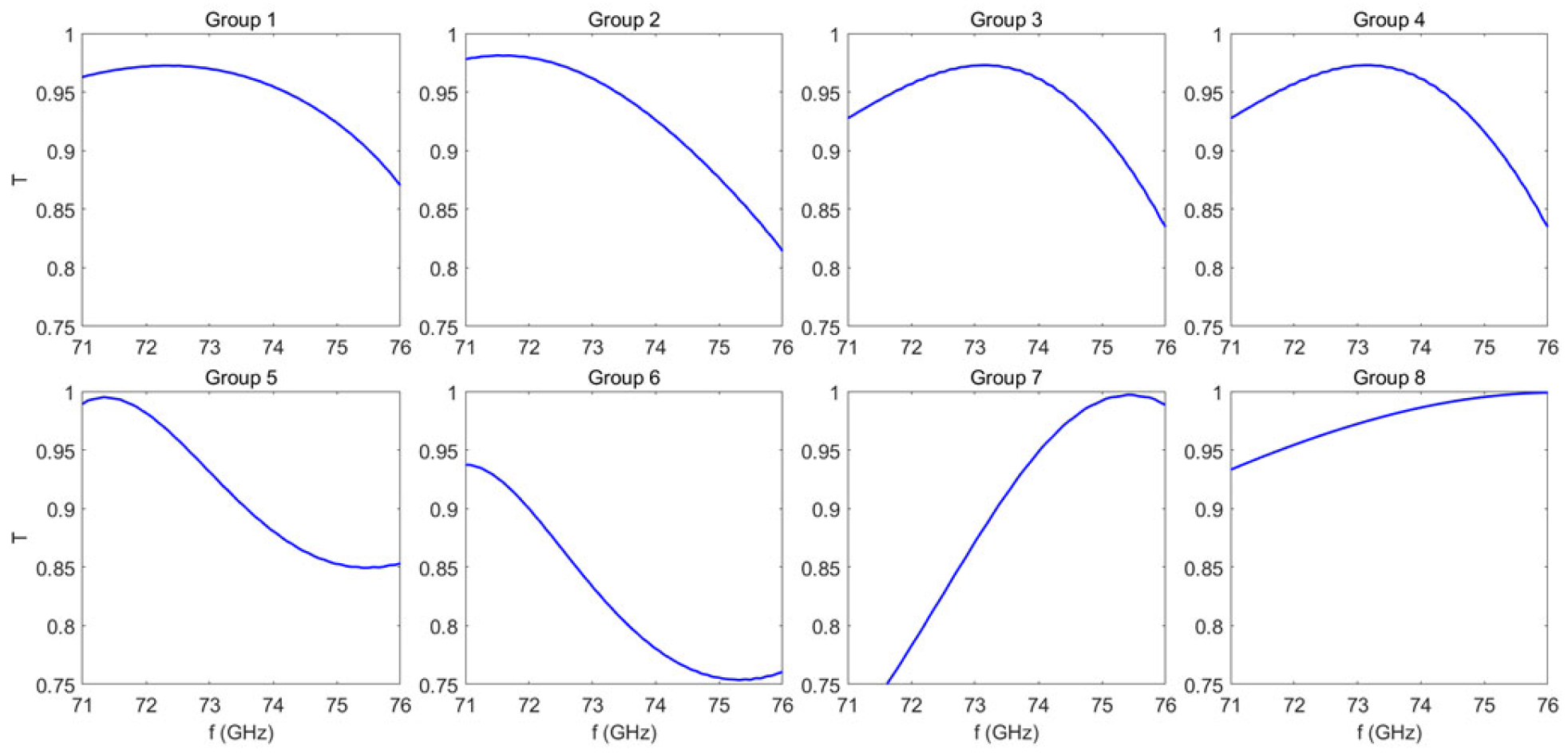
The all-dielectric metasurface consists of cylindrical unit cells and is divided into eight sectors, each featuring cylinders with distinct heights and radii. The unit cell period is mm, the substrate thickness is mm, the cylinder height ranges from 1 to 4.5 mm, and the cylinder radius ranges from 0.2 to 0.9 mm. Figure 1a shows the 8 regions on the surface and Figure 1b gives the structure of one unit cell. The metasurface was fabricated using DLP stereolithography 3D printing technology with Al2O3 () as the base material. This all-dielectric design effectively avoids issues commonly associated with metallic metasurfaces under high-power operation, such as ohmic loss, thermal effects, and insufficient power capacity. The fabrication process began with the preparation of a high-solid-loading alumina photocurable slurry, followed by DLP printing to obtain a ceramic green body. A precise temperature-controlled debinding process was then employed to remove organic components, and the structure was subsequently densified via high-temperature sintering. The resulting Al2O3 metasurface exhibits a surface smoothness of 0.2–0.6 μm. The metasurface was designed and simulated using ANSYS Lumerical FDTD (2023 R1) software. During parameter sweeping, a plane wave at 73.5 GHz was normally incident upon the unit cell structure. Periodic boundary conditions were applied in the x and y directions, while the z direction was set as an MPL (matched boundary layer). A sweep accuracy of 2 was adopted, and a fine override mesh with a grid size of 0.08 mm was added over the cylindrical structure to enhance simulation precision. Figure 2 shows the results of the parameter sweeping, where (a) presents the swept transmittance (T) and (b) presents the swept phase. From (b), eight sets of structures were selected whose phases are as close as possible to the center of each phase division (target phase), with a maximum deviation not exceeding 15%. Meanwhile, these structures exhibit the highest possible transmittance in (a). Additionally, since the parameter sweeping was conducted at 73.5 GHz, the transmittance within the 71–76 GHz frequency band must also be fully considered, requiring that the overall transmittance of the selected structures within this band is no less than 0.75. Based on these criteria, the eight sets of structures shown in Table 1 were ultimately determined. Table 1 presents the diameter and height of the cylinders in the eight regions, where T represents the transmission coefficient, target phase denotes the desired phase shift of the structure, phase indicates the actual phase shift achieved by our structure, and phase deviation represents the error between the actual phase shift and the desired phase shift. It can be observed from the table that among the eight metasurface unit structures, only the seventh structure exhibits the largest phase error, which is 14.258%, yet it remains below 15%, indicating that the phase distribution of the metasurface is still relatively uniform. Figure 3 illustrates the transmittance of the eight metasurface structures within the 71–76 GHz frequency range. It can be seen that the transmittance of all eight structures is greater than 0.75, demonstrating the excellent transmittance of the metasurface.
Figure 1.
(a) Metasurface arrangement and (b) unit structure.
Figure 2.
(a) Transmittance distribution ranging from 0 to 1.0 and (b) phase distribution from −π to π of cylindrical unit structures with different r and h values.
Table 1.
The cylinder height and radius in the 8 regions.
Figure 3.
Transmittance of the 8 different unit structures on the metasurface.
The essence of converting an incident plane wave into a vortex wave using a metasurface lies in applying an azimuthal phase shift compensation to the incident wave. To generate a vortex wave with topological charge , the phase of the plane wave must be rotated by in the azimuthal direction. This process can be described by Equation (1). The eight selected structures are arranged according to Equation (1).
Here, is the phase value at point , is the topological charge of the vortex wave, and calculates the angle of relative to the origin, typically in the range of .
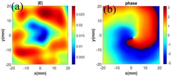
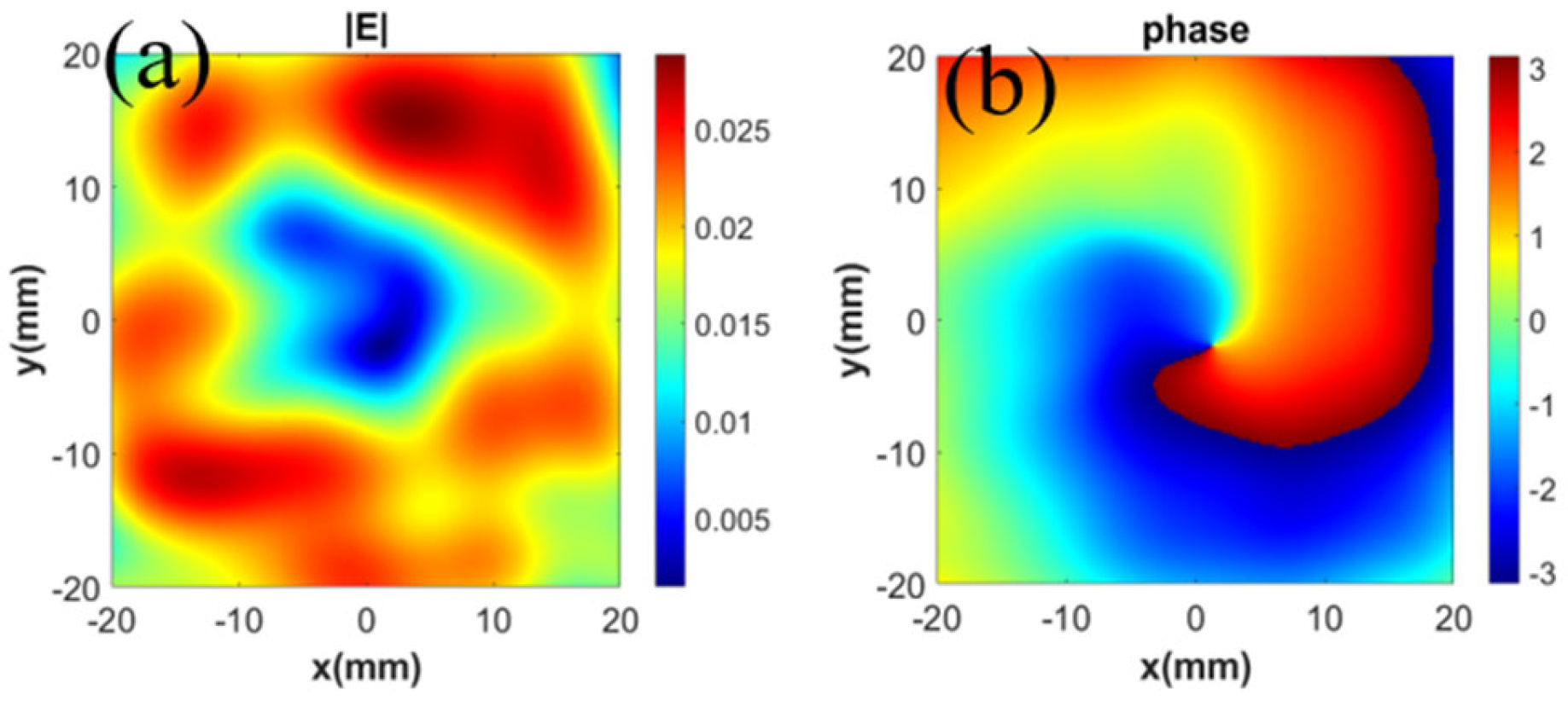
To simulate the actual operating process in which the TE10 waveguide mode wave output from the E-band traveling wave tube is radiated by the horn antenna and subsequently converted into a vortex electromagnetic wave carrying a topological charge of via the metasurface, the following simulation setup was established. A TE10 mode wave was excited at the input port of the horn antenna. The metasurface was positioned mm behind the horn antenna, and the vortex wave field was probed on a detection plane located mm behind the metasurface. The simulation results are shown in Figure 3. It is seen that the electric field intensity of vortex electromagnetic waves with a topological charge of exhibits a ring-shaped distribution with a central singularity, as shown in Figure 4a, while the phase displays a clockwise helical pattern, as shown in Figure 4b. Vortex electromagnetic waves can be decomposed into the superposition of vortex modes with different topological charges [21], as described in Equations (2) and (3).
where represents the normalized complex electric field amplitude at the azimuthal angle on a circumference of radius , and denotes the complex amplitude coefficient of the vortex mode with topological charge at that radius.
Figure 4.
Simulated electric field pattern (a) and phase pattern (b) of vortex wave with topological charge .
To characterize the quality of a generated vortex electromagnetic wave of a specific mode, the physical quantity of mode purity is defined. It refers to the proportion of the wave energy of the target OAM mode (e.g., with topological charge ) relative to the total energy of the generated vortex electromagnetic wave. In the measured cross-sectional electric field intensity and phase distribution maps, discrete sampling is performed on a circle centered at the phase singularity of the vortex electromagnetic wave, with a radius (r0) extending from the singularity to the point of maximum electric field intensity (where the OAM electromagnetic wave energy is relatively concentrated, leading to higher accuracy in mode purity calculation). This process yields a discrete complex electric field sequence , where n = 0, 1, 2…, N − 1, and N is the total number of sampling points. Subsequently, a discrete Fourier transform is applied to the sequence to obtain the mode coefficients for each order, as shown in Equation (4):
The power carried by each mode is proportional to the square of its coefficient; in this paper, we take .
According to the Nyquist sampling theorem, N equally spaced sampling points can resolve a maximum of N angular harmonic modes without aliasing. The range of topological charges is [−L,L], where L = [N/2]. The calculation formula for the purity of the target mode can then be expressed as Equation (5):
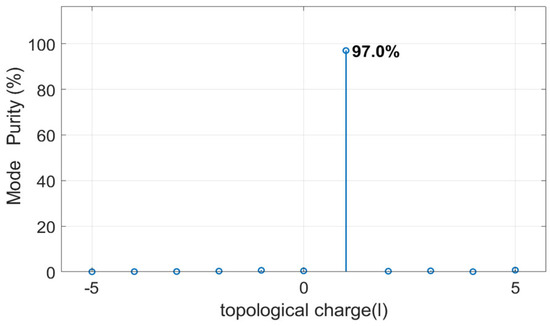
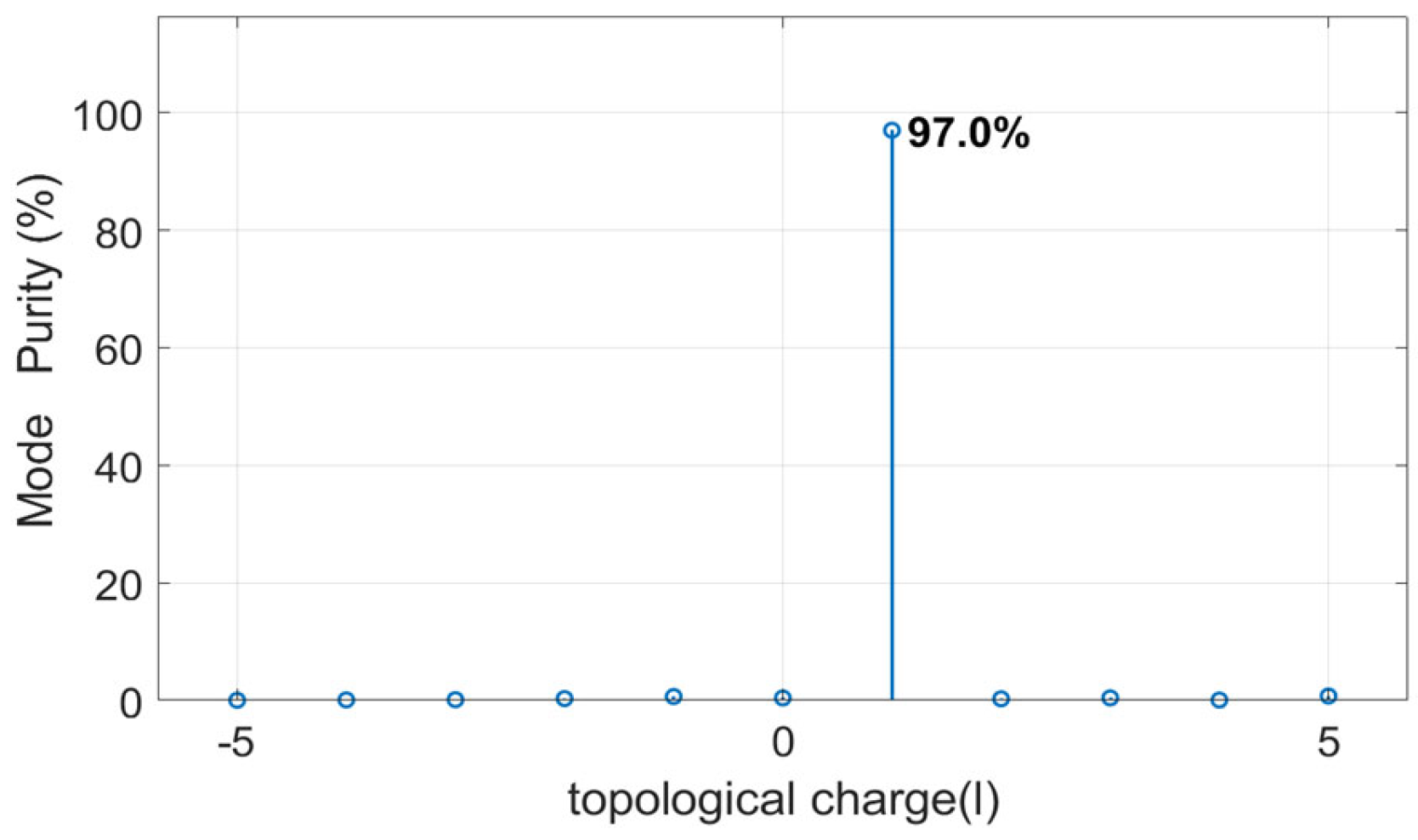
where is the total power of all vortex modes. Based on the electric field strength and phase distribution obtained from our simulation, we calculated that the mode purity of the vortex electromagnetic wave with topological charge of generated by the system is 97%, as shown in Figure 5.
Figure 5.
Simulated mode purity of the vortex wave.
3. Fabrication and Experimental Testing
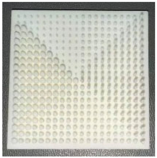
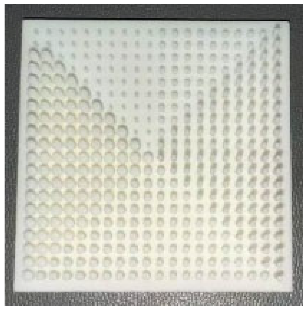
The metasurface is manufactured using Digital Light Processing (DLP) photo-polymerization 3D printing technologies and is shown in Figure 6. The surface smoothness of the processed metasurface is between 0.2 and 0.6 μm, and the maximum error in the unit structure radius of the actual metasurface is measured to be 0.05 mm. By increasing the radius of each unit of the metasurface by 0.05 mm, the maximum error caused by 3D printing on the formation of vortex electromagnetic waves was verified through simulation. The results are shown in Figure 7 and Figure 8.
Figure 6.
The metasurface manufactured by DLP.
Figure 7.
After considering the effects of the processing accuracy caused by 3D printing of the metasurface, (a) is the simulated field distribution and (b) is the phase distribution.
Figure 8.
Vortex wave mode purity after considering the effects of the processing accuracy caused by 3D printing of the metasurface.
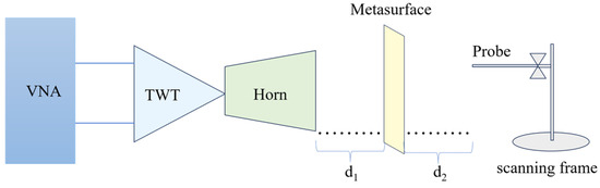
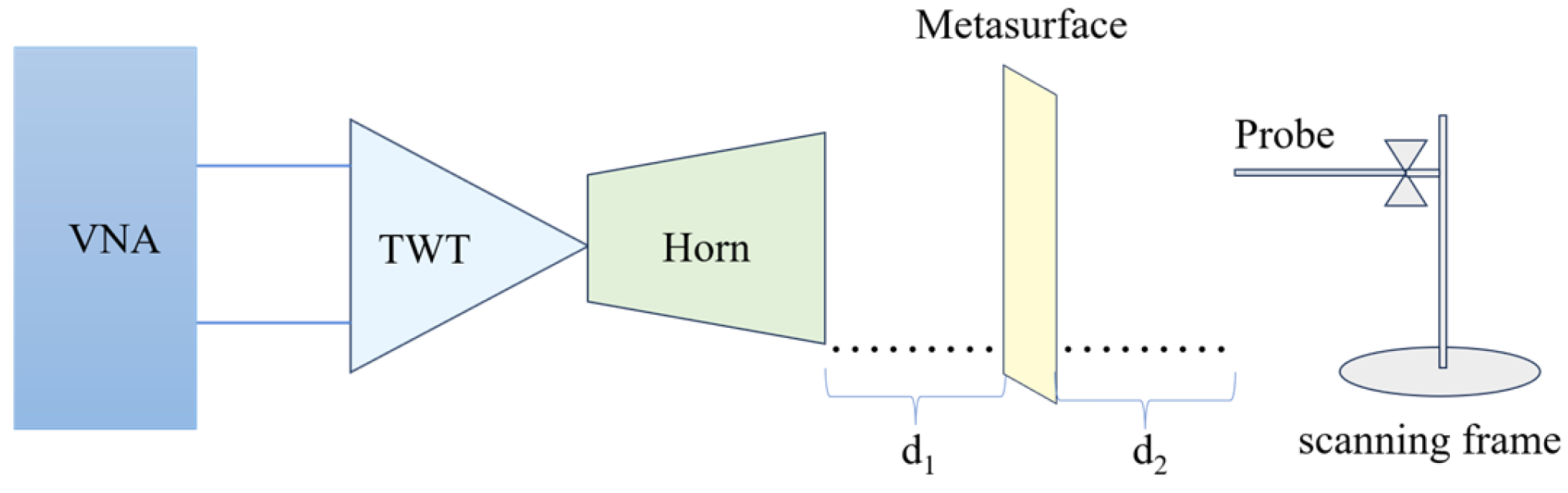
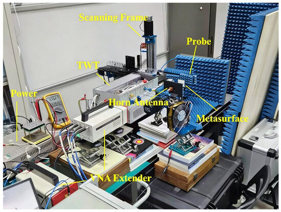
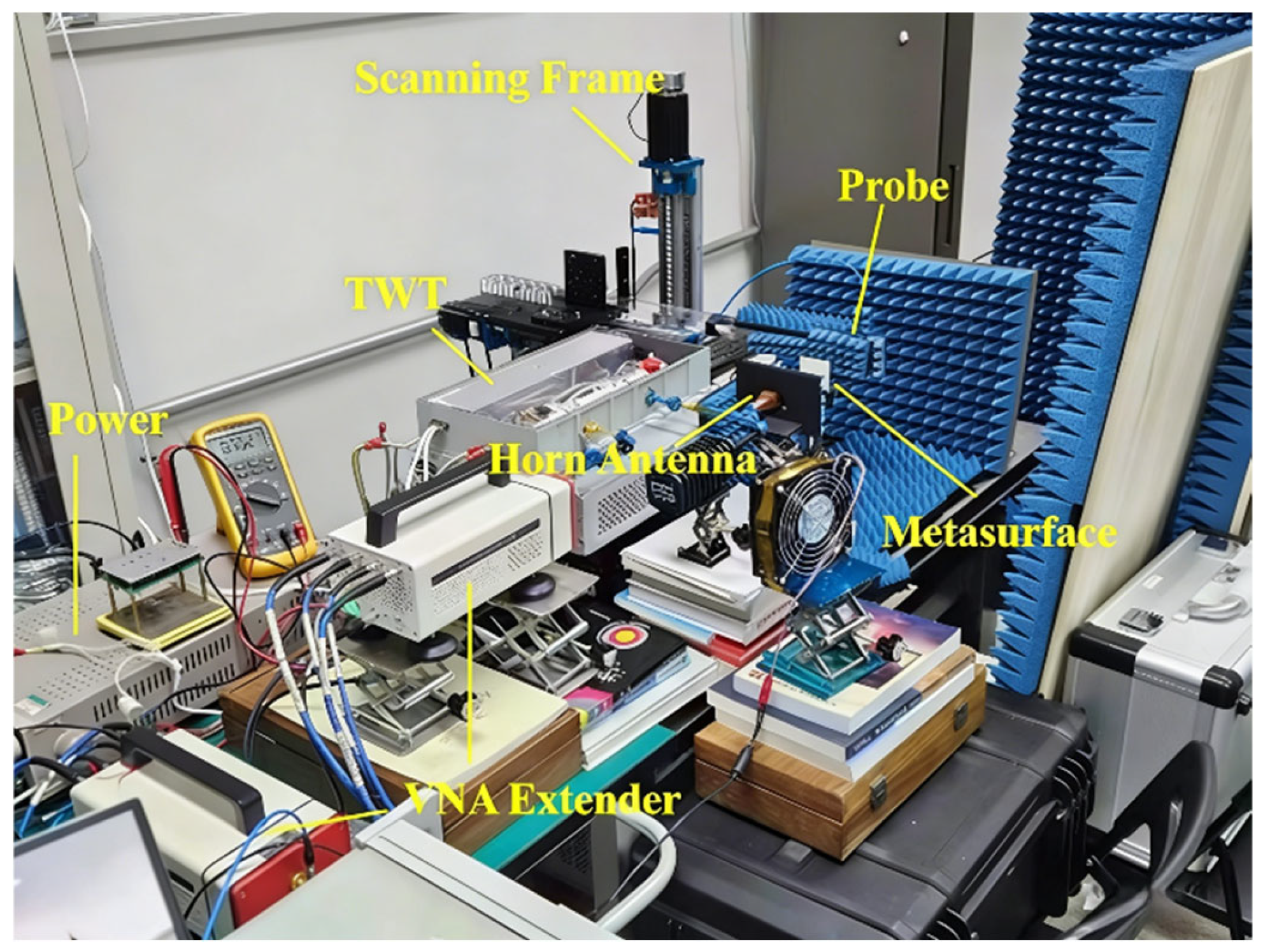
To experimentally verify the generation of vortex electromagnetic waves with a topological charge of by the designed radiating system, an experimental setup is constructed, comprising a “VNA + frequency extender + TWT + horn antenna + metasurface + waveguide probe” for near-field testing. The experimental schematic is shown in Figure 9 and the experimental scene is shown in Figure 10.
Figure 9.
Schematic diagram of near-field scanning.
Figure 10.
Near-field testing experiment setup.
For near-field measurements, a KEYSIGHT PNA-X N5245A vector network analyzer (DC–50 GHz)(Keysight Technologies, Santa Rosa, CA, USA), a Ceyear 3643P frequency extender (Chengdu Cevear Technology Co., Ltd., Chengdu, China) module (75–110 GHz), and an Aotai Technology AT-PBA-12A-2.0 waveguide probe (60–90 GHz) (Aotai Technology Co., Ltd., Shanghai, China) were employed. To prevent the high-power electromagnetic wave output from the traveling wave tube from damaging the vector network analyzer, an attenuator (XB-VA10-25) (Beijing XinBo Microwave Technology Co., Ltd., Beijing, China) was added at the input of the traveling wave tube and a 10 dB coupler (XB-WDC12-10) (Beijing XinBo Microwave Technology Co., Ltd., Beijing, China) was inserted at its output. With the exception of the coaxial cable connection between the probe and the frequency extender receiver, all interconnections were implemented using rigid waveguide connections.
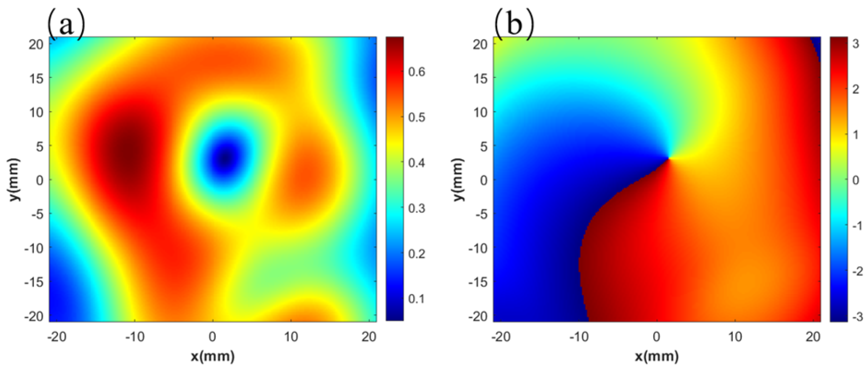
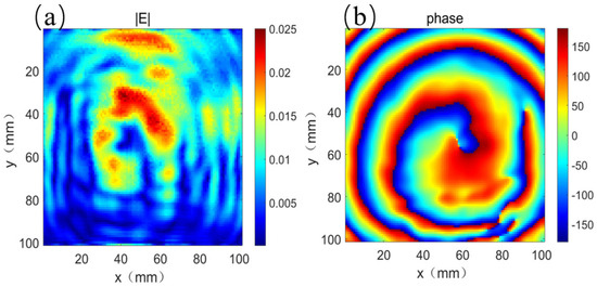
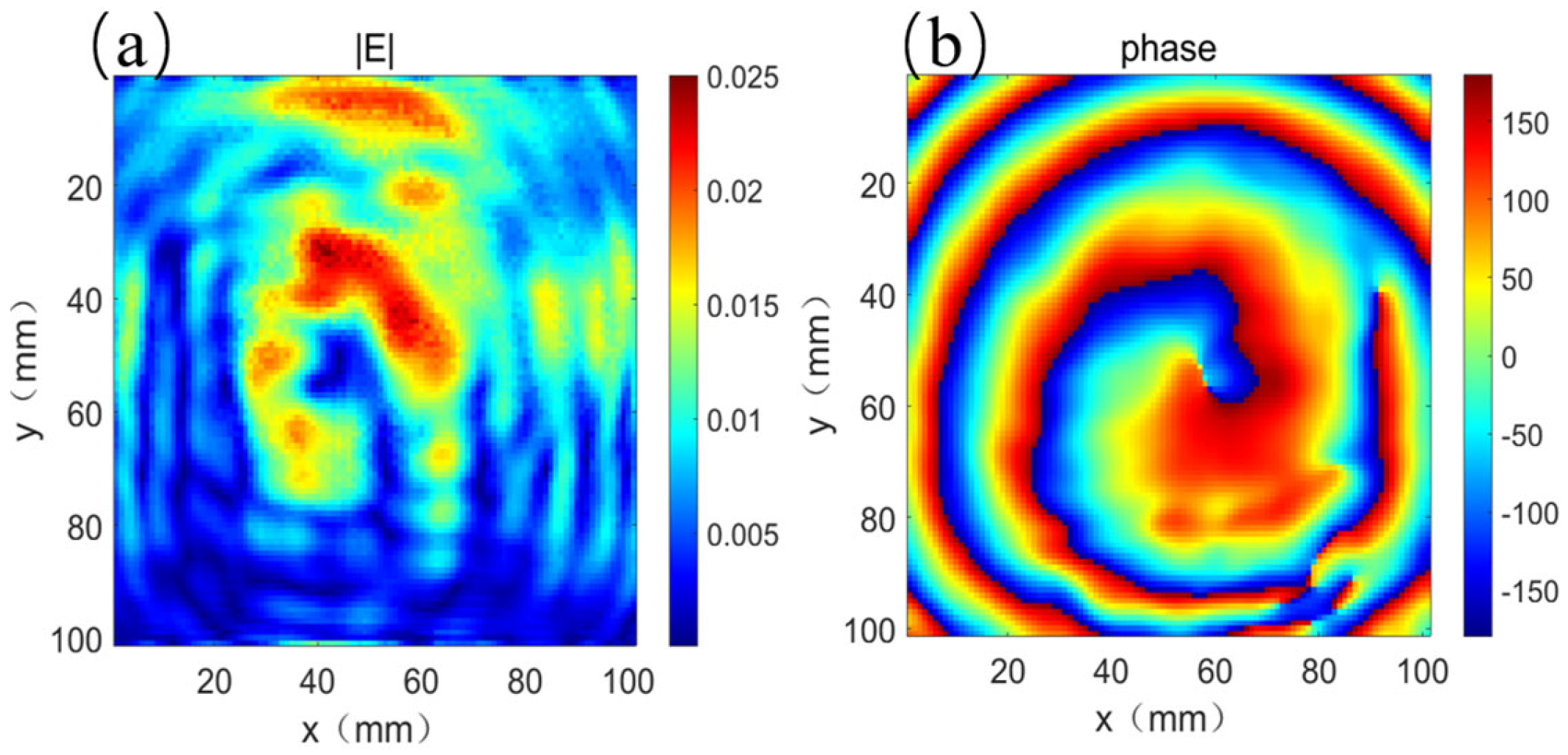
A continuous wave at 73.5 GHz was output from the vector network analyzer. The horn antenna was directly connected to the output port of the traveling wave tube, and the metasurface was placed at a distance of mm behind the horn antenna. A computer-controlled 3D scanning stage was used to position the probe, which scanned a 100 mm × 100 mm plane located at mm behind the metasurface with a step size of 1 mm. The complex S21 parameters over the plane were recorded, yielding the complete electric field intensity distribution and phase distribution of the vortex wave. The topological charge on this cross-section was determined to be , as shown in Figure 11. The field strength is mainly distributed in the ring outside the center, and the phase exhibits vortex wave characteristics with topological charges, rotating clockwise for one cycle.
Figure 11.
(a) Tested electric field intensity pattern and (b) tested phase pattern of the vortex wave with topological charge .
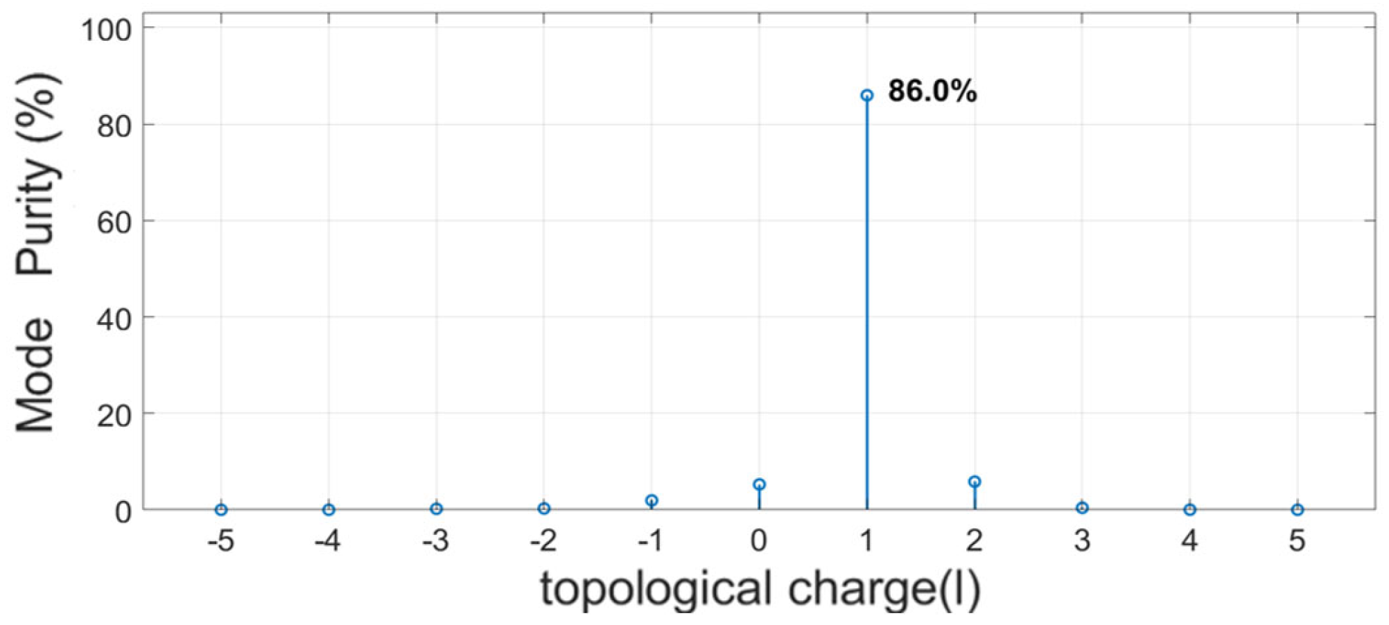
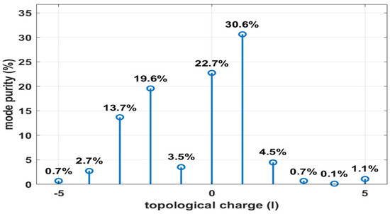
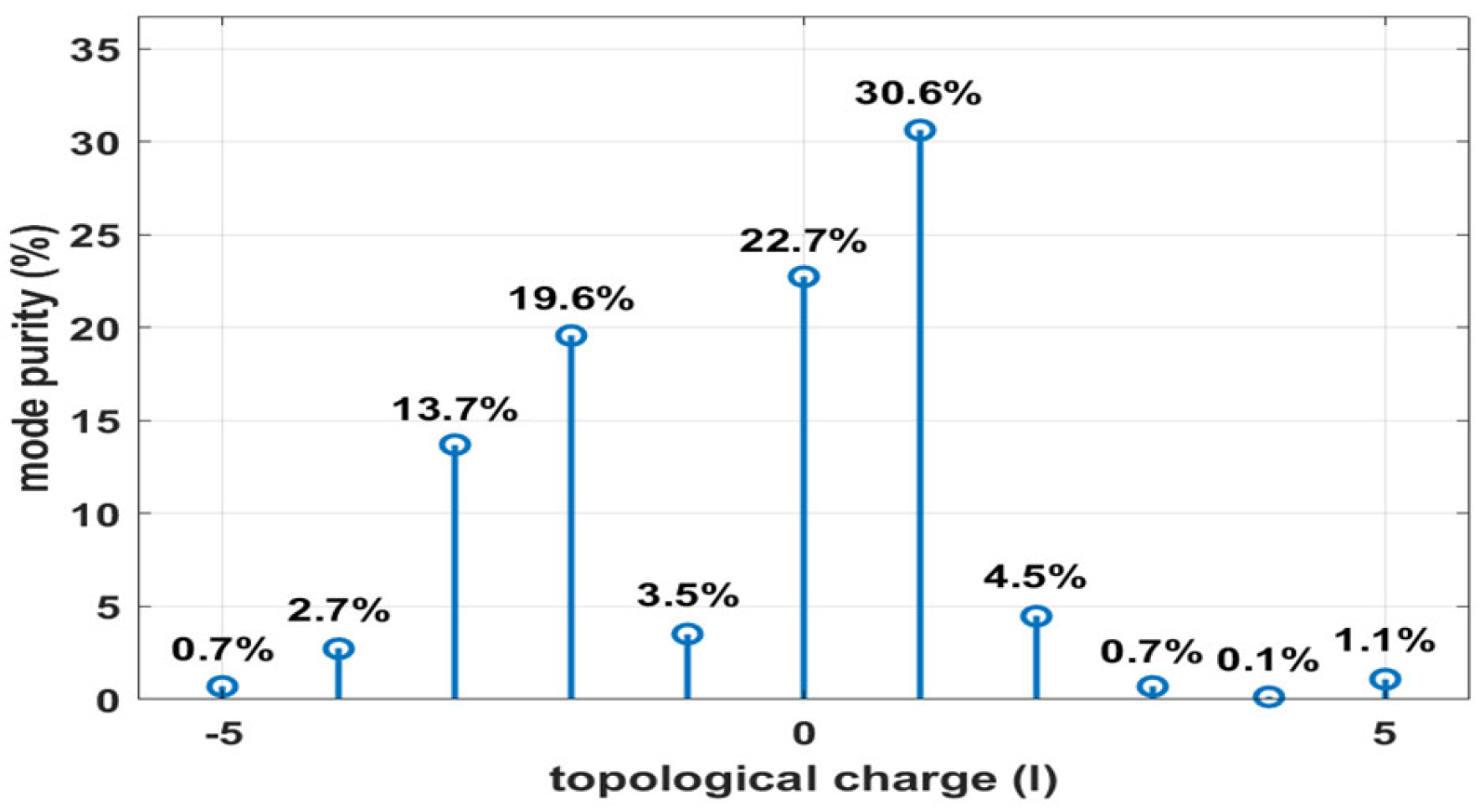
Based on the measured electric field intensity and phase, the mode purity distribution is calculated, as shown in Figure 12. The measured vortex beam with the target topological charge has a mode purity of 30.6%, which is smaller than the simulation expectation. This discrepancy is primarily attributed to the multi-reflection environment and the finite aperture of the metasurface. The experimental setup, not in an anechoic chamber, introduced significant reflections. The probe-side surroundings and the region behind the horn antenna both acted as reflective surfaces. Electromagnetic waves undergo multiple reflections within the experiment space, and a portion of the wave is reflected from the probe side back to the metasurface as components with and , which are subsequently re-modulated into and modes, respectively. The process on the horn antenna side follows a similar sequence but in the opposite direction. When the metasurface receives the wave from the horn side, it modulates the wave again, converting it into the mode. Through further multiple reflections, higher-order modes such as are generated. Due to the absorbing material placed in front of the metasurface, the reflectivity of the two sides is asymmetric. The horn antenna side exhibits stronger reflection, resulting in more pronounced and components, whereas the probe side contributes weaker and components. This explains the relatively larger proportions of and modes observed in Figure 8. Additionally, because of the limited metasurface aperture (42 mm × 42 mm), only part of the incident plane wave passes through the metasurface, further increasing the component. In summary, the measured mode spectrum results from the superposition of the main mode and spurious modes generated through the described multi-path reflections. Combining the principal identified components yields an overall mode purity of 86.6%.
Figure 12.
Purity diagram of vortex wave experimental modes.
4. Conclusions
This paper presents a method for generating vortex electromagnetic waves with a topological charge of in the E-band using a traveling wave tube and a transmissive metasurface. The experiment successfully detected vortex waves carrying the designated topological charge of which dominated the measured signal, thereby validating the feasibility of the proposed scheme.
However, the current work still has some limitations. First, the experimentally measured mode purity of the vortex wave is only 30.6%, significantly lower than the simulated value of 97%. This discrepancy is mainly attributed to extensive reflections caused by the experimental environment. If the effects of these environmental reflections are eliminated, the estimated mode purity could reach 86.6%, which is very close to the 86% obtained from simulations incorporating corrected 3D printing fabrication errors. This indicates that the measured experimental results were primarily caused by the experimental environment, rather than issues related to the design and fabrication of the metasurface. Second, due to the lack of high-power millimeter-wave measurement equipment, this study did not characterize the actual power level of the generated vortex waves.
To overcome these limitations, future efforts could focus on improving fabrication techniques and upgrading the experimental environment to enhance mode purity. Additionally, a dedicated high-power measurement system should be developed to characterize the output power and far-field radiation patterns of the vortex waves, laying the groundwork for future long-distance wireless OAM communication in the E-band. Despite the current challenges, the proposed traveling wave tube and metasurface integration remains a promising solution for future high-power millimeter-wave OAM applications.
Author Contributions
Conceptualization, J.F. and H.Z.; methodology, H.Z. and P.P.; software, H.Z.; validation, H.Z., S.L. and Y.Z.; formal analysis, H.Z.; investigation, H.Z.; resources, J.F.; data curation, H.Z.; writing—original draft preparation, H.Z.; writing—review and editing, J.F. and C.D.; visualization, H.Z.; supervision, J.F. and C.D.; project administration, J.F.; funding acquisition, J.F. All authors have read and agreed to the published version of the manuscript.
Funding
This research was funded by the National Natural Science Foundation of China, grant number 62131006, and the National Key Laboratory of Science and Technology on Vacuum Electronics.
Data Availability Statement
The data presented in this study are available within the article.
Conflicts of Interest
Authors Haojie Zhu, Jinjun Feng, Pan Pan, and Shishuo Liu were employed by the Beijing Vacuum Electronics Research Institute. The remaining authors declare that the research was conducted in the absence of any commercial or financial relationships that could be construed as potential conflicts of interest. The funders had no role in the design of the study; in the collection, analyses, or interpretation of data; in the writing of the manuscript; or in the decision to publish the results.
Abbreviations
| TWT | Traveling wave tube |
| OAM | Orbital angular momentum |
| MIMO | Multiple input multiple output |
| DLP | Digital Light Processing |
References
- Allen, L.; Beijersbergen, M.W.; Spreeuw, R.J.C.; Woerdman, J.P. Orbital angular momentum of light and the transformation of Laguerre-Gaussian laser modes. Phys. Rev. A 1992, 45, 8185. [Google Scholar] [CrossRef] [Scilit] [PubMed]
- Thidé, B.; Then, H.; Sjöholm, J.; Palmer, K.; Bergman, J.; Carozzi, T.D.; Istomin, Y.N.; Ibragimov, N.H.; Khamitova, R. Utilization of photon orbital angular momentum in the low-frequency radio domain. Phys. Rev. Lett. 2007, 99, 087701. [Google Scholar] [CrossRef] [Scilit] [PubMed]
- Tamburini, F.; Mari, E.; Thidé, B.; Barbieri, C.; Romanato, F. Experimental verification of photon angular momentum and vorticity with radio techniques. Appl. Phys. Lett. 2011, 99, 204102. [Google Scholar] [CrossRef] [Scilit]
- Zhang, W.; Zheng, S.; Hui, X.; Dong, R.; Jin, X.; Chi, H.; Zhang, X. Mode division multiplexing communication using microwave orbital angular momentum: An experimental study. IEEE Trans. Wirel. Commun. 2016, 16, 1308–1318. [Google Scholar] [CrossRef] [Scilit]
- Yagi, Y.; Sasaki, H.; Yamada, T.; Lee, D. 200 Gb/s wireless transmis sion using dual-polarized OAM-MIMO multiplexing with uniform circular array on 28 GHz band. IEEE Antennas Wirel. Propag. Lett. 2021, 20, 833–837. [Google Scholar] [CrossRef] [Scilit]
- Lin, M.; Gao, Y.; Liu, P.; Liu, J. Theoretical analyses and design of circular array to generate orbital angular momentum. IEEE Trans. Antennas Propag. 2017, 65, 3510–3519. [Google Scholar] [CrossRef] [Scilit]
- Chen, J.J.; Lu, Q.N.; Dong, F.F.; Yang, J.J.; Huang, M. Wireless OAM transmission system based on elliptical microstrip patch antenna. Opt. Express 2016, 24, 11531–11538. [Google Scholar] [CrossRef] [Scilit] [PubMed]
- Liang, J.; Zhang, S. Orbital angular momentum (OAM) generation by cylinder dielectric resonator antenna for future wireless communications. IEEE Access 2016, 4, 9570–9574. [Google Scholar] [CrossRef] [Scilit]
- Ren, Y.; Li, L.; Xie, G.; Yan, Y.; Cao, Y.; Huang, H.; Ahmed, N.; Zhao, Z.; Liao, P.; Zhang, C. Line-of-sight millimeter-wave communications using orbital angular momentum multiplexing combined with conventional spatial multiplexing. IEEE Trans. Wirel. Commun. 2017, 16, 3151–3161. [Google Scholar] [CrossRef] [Scilit]
- Nevels, R.; Kish, L. Twisted waves: Concept and limitations. In 2013 IEEE Antennas and Propagation Society International Symposium (APSURSI); IEEE: Piscataway, NJ, USA, 2013; pp. 1460–1461. [Google Scholar]
- Tamburini, F.; Mari, E.; Parisi, G.; Spinello, F.; Oldoni, M.; Ravanelli, R.A.; Coassini, P.; Someda, C.G.; Thidé, B.; Romanato, F. Tripling the capacity of a point-to-point radio link by using electromagnetic vortices. Radio Sci. 2015, 50, 501–508. [Google Scholar] [CrossRef] [Scilit]
- Qin, F.; Wan, L.; Li, L.; Zhang, H.; Wei, G.; Gao, S. A transmission metasurface for generating OAM beams. IEEE Antennas Wirel. Propag. Lett. 2018, 17, 1793–1796. [Google Scholar] [CrossRef] [Scilit]
- Liu, X.; Gu, M.; Tian, Y.; Zheng, M.; Fang, B.; Hong, Z.; Tan, C.L.; Jing, X. Research progress on generating perfect vortex beams based on metasurfaces. Opto-Electron. Sci. 2026, 4, 250007. [Google Scholar] [CrossRef] [Scilit]
- Zhan, H.; Gu, M.; Tian, Y.; Feng, H.; Zhu, M.; Zhou, H.; Jin, Y.; Tang, Y.; Li, C.; Fang, B.; et al. Review for wireless communication technology based on digital encoding metasurfaces. Opto-Electron. Adv. 2025, 8, 240315. [Google Scholar] [CrossRef] [Scilit]
- Wang, C.; Yang, Y.; Wang, Y.; Wu, J.; Huang, X.; Jin, J.; Yang, H. Wideband dual-mode vortex wave metasurface based on distance inversion method. IEEE Trans. Antennas Propag. 2024, 72, 9401–9410. [Google Scholar] [CrossRef] [Scilit]
- Xu, H.X.; Hu, G.; Jiang, M.; Tang, S.; Wang, Y.; Wang, C.; Huang, Y.; Ling, X.; Liu, H.; Zhou, J. Wavevector and frequency multiplexing performed by a spin-decoupled multichannel metasurface. Adv. Mater. Technol. 2020, 5, 1900710. [Google Scholar] [CrossRef] [Scilit]
- Xu, H.X.; Hu, G.; Li, Y.; Han, L.; Zhao, J.; Sun, Y.; Yuan, F.; Wang, G.-M.; Jiang, Z.H.; Ling, X.; et al. Interference-assisted kaleidoscopic meta-plexer for arbitrary spin-wavefront manipulation. Light Sci. Appl. 2019, 8, 3. [Google Scholar] [CrossRef] [Scilit] [PubMed]
- Fukunari, M. Generation of high-power and high-order terahertz vortex beams using a gyrotron. In Proceedings of the 42st SPP Physics Conference and Annual Meeting, Batangas City, Philippines, 3–6 July 2024. [Google Scholar]
- Wang, L.; Chen, Y.; Wang, C.; Song, H.; Hua, J.; Huang, R.; Chen, M.; Zhang, J.; Sheng, Z.-M. Terahertz vortices with tunable topological charges from a laser–plasma channel. Adv. Photonics Nexus 2025, 4, 036004. [Google Scholar] [CrossRef] [Scilit]
- Shi, Y.; Zhang, X.; Arefiev, A.; Shen, B. Advances in laser-plasma interactions using intense vortex laser beams. Sci. China Phys. Mech. Astron. 2024, 67, 295201. [Google Scholar] [CrossRef] [Scilit]
- Jack, B.; Padgett, M.J.; Franke-Arnold, S. Angular diffraction. New J. Phys. 2008, 10, 103013. [Google Scholar] [CrossRef] [Scilit]

Disclaimer/Publisher’s Note: The statements, opinions and data contained in all publications are solely those of the individual author(s) and contributor(s) and not of MDPI and/or the editor(s). MDPI and/or the editor(s) disclaim responsibility for any injury to people or property resulting from any ideas, methods, instructions or products referred to in the content. |
© 2026 by the authors. Licensee MDPI, Basel, Switzerland. This article is an open access article distributed under the terms and conditions of the Creative Commons Attribution (CC BY) license.