


Abstract
To address the state-of-charge (SOC) imbalance and the limited convergence speed of conventional SOC balancing strategies in cascaded power conversion systems (PCSs) under practical grid-connected conditions, this paper investigates the control of cascaded H-bridge energy storage converters under multiple operating scenarios. The three-phase cascaded H-bridge topology is first reviewed, followed by the development of a hierarchical control framework for the cascaded PCSs. The corresponding overall control block diagram is then presented. Based on this, a unified power equalization control strategy based on the third harmonic injection is proposed, which ensures the effectiveness of power control, SOC equalization control, and fault-tolerant control by increasing the injection range, and it guarantees the normal operation of the cascaded PCSs. Considering the phase relationship of the PCS output voltage after the third harmonic injection, the maximum zero-sequence voltage injection range is found, and the constraints of zero-sequence voltage injection are derived. A MATLAB/Simulink simulation model and a real-time hardware-in-the-loop (HIL) platform based on the MT6016 are established to validate the effectiveness and practical feasibility of the proposed control strategy.
1. Introduction
With the rapid evolution of modern power systems, renewable energy generation has become an increasingly significant component of grid operations [1]. In particular, the penetration level of renewable energy sources, such as wind and photovoltaic power, has been steadily increasing, accompanied by a rapid growth in grid-connected battery energy storage systems [2]. In practice, modern power grids exhibit various non-ideal characteristics, including voltage unbalance, harmonic distortion, DC offset, and frequency deviations [3]. When the grid-side voltage is unbalanced, it will cause unbalanced output current of the energy storage system, leading to the degradation of system performance and even damage [4].
With the increasing penetration of renewable energy sources, cascaded power conversion systems (PCSs) with integrated battery energy storage have become a promising solution for medium- and high-voltage grid applications due to their modular structure, scalability, and superior harmonic performance [5,6,7]. However, under practical grid-connected conditions, voltage unbalance, parameter inconsistency among modules, and fault events inevitably lead to inter-phase power imbalance, which further results in state-of-charge (SOC) divergence among battery packs [8,9].
Under unbalanced grid voltage conditions, cascaded energy storage PCSs inevitably experience asymmetric phase currents and power oscillations, which pose significant challenges to stable grid-connected operations. To address this issue, various power decoupling and positive–negative sequence control strategies have been proposed to achieve independent regulation of active and reactive power under asymmetric grid conditions [10,11,12]. These methods effectively suppress power oscillations and ensure current balance; however, they mainly focus on grid-side power control and do not explicitly consider the resulting inter-phase power imbalance on the DC side.
The inter-phase power imbalance caused by grid asymmetry and parameter inconsistency further leads to divergence in the state of charge (SOC) among battery packs in cascaded energy storage systems. To mitigate SOC imbalance, zero-sequence voltage injection has been widely adopted in star-connected cascaded H-bridge systems, as it enables power redistribution among phases without introducing unbalanced currents [13,14]. Nevertheless, the achievable regulation range of the zero-sequence voltage is fundamentally constrained by the modulation margin of individual H-bridge cells, resulting in limited SOC balancing speed, especially under severe grid unbalance or fault conditions.
Alternatively, negative sequence current-based SOC balancing strategies have been reported to enhance inter-phase power regulation capability [15]. Although these approaches can accelerate SOC balancing, they often deteriorate output power quality and increase current harmonic distortion, which restricts their applicability in long-term grid-connected operations [16].
Third harmonic injection has been extensively studied as an effective technique to improve DC voltage utilization and extend the linear modulation range in multilevel converters [17,18,19]. By properly injecting third harmonic components into the modulation waveform, the peak value of the phase voltage can be reduced without affecting the fundamental output power, thereby increasing the available voltage margin. Nevertheless, existing studies mainly focus on power quality improvement and modulation enhancement, while the potential of third harmonic injection for unified SOC balancing and fault-tolerant control in cascaded energy storage PCSs has not been fully explored.
In this context, this paper proposes a unified power-balancing control strategy for cascaded PCSs based on third harmonic injection. The main contributions of this work are summarized as follows:
- (1)
- A unified control framework is established to simultaneously address power imbalance under grid voltage unbalance, inter-phase SOC balancing, and fault-tolerant operation;
- (2)
- The maximum zero-sequence voltage injection range is analytically derived, and its limitation under conventional modulation is identified;
- (3)
- Third harmonic injection is introduced to significantly expand the zero-sequence voltage regulation range, leading to a notable improvement in SOC balancing speed and modulation margin, which is quantitatively verified through comparative simulations.
2. Control Strategy for Cascaded PCSs
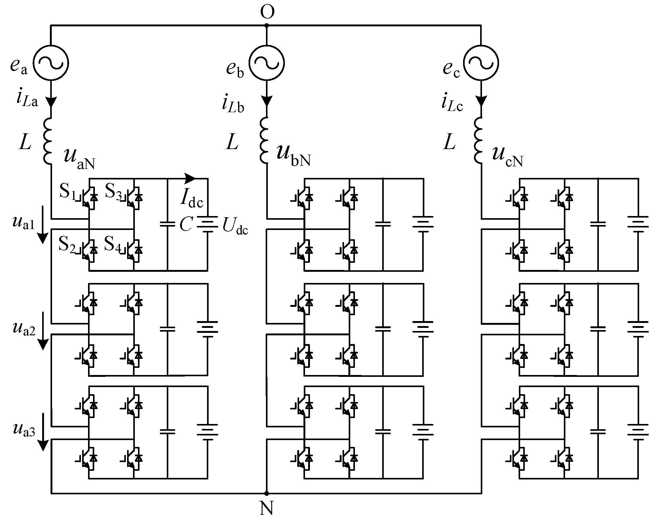
Figure 1 shows the main circuit topology of the cascaded energy storage PCSs. Under the condition of the same capacity, the star connection method requires fewer modules and a simpler control strategy compared with the delta connection method. Therefore, the star connection method is adopted in this paper, with three H-bridge converters cascaded per phase as power modules and lithium-ion batteries selected as the energy storage medium [7].
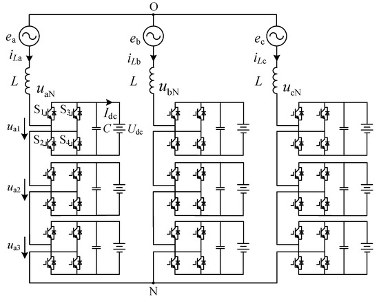
Figure 1.
Cascade energy storage PCS—main circuit topology diagram.
Due to the particularity of the topological structure, the SOC balancing control and fault-tolerant control are adopted simultaneously. The main research content of this section includes three control strategies for cascaded PCS, namely power control, SOC balancing control, and fault-tolerant control, and an in-depth discussion is conducted on the basis of these strategies.
2.1. System-Level Power Control Under Grid Voltage Unbalance
When the grid voltage is unbalanced, both the grid voltage and the output current contain negative sequence components. To ensure the safe and stable operation of the PCS, the grid voltage and output current are decomposed into positive and negative sequence components, which are then independently controlled in a dual synchronous rotating reference frame. The negative sequence current caused by unbalanced conditions is compensated, thereby suppressing the impact of voltage unbalance on the performance of the energy storage PCS. When the cascaded PCS operates in grid-connected charging/discharging mode, according to the instantaneous power theory, the positive and negative sequence reference values of the grid-side current of the system are respectively:
In the formula, , , , and are the d-axis and q-axis components of the positive and negative sequence reference values of the grid-side current; , , , and are the positive and negative sequence components of the grid voltage on the d-axis and q-axis; P* and Q* are the given active and reactive power.
The decoupling of active and reactive currents is achieved through the PI control for independent regulation. The d-axis and q-axis components of the given positive and negative sequence voltage values can be expressed respectively as:
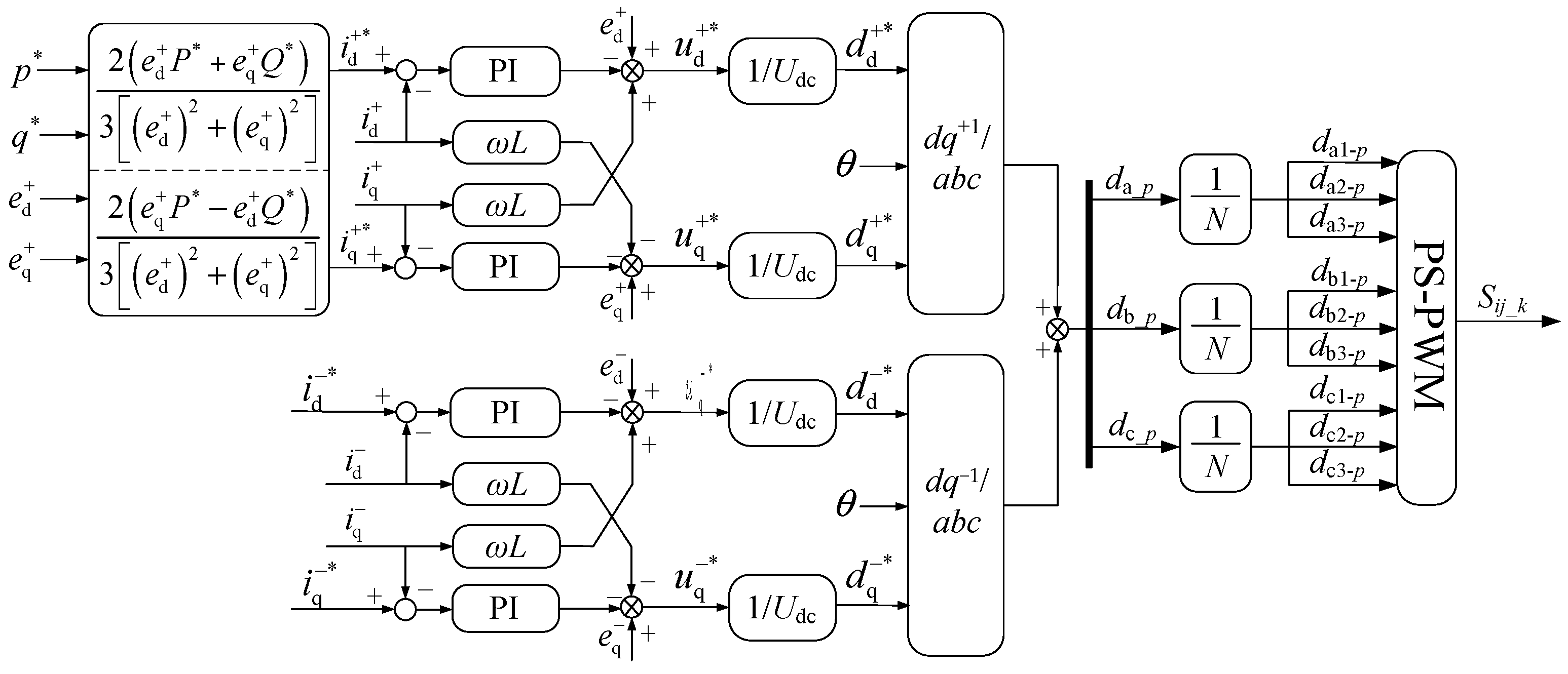
Based on Equations (2) and (3), a phase-locked loop (PLL) based on the dual second-order generalized integrator-quadrature signal generator (SOGI-QSG) can be adopted in the system. Voltage feedforward current decoupling control is implemented for the positive and negative sequence current components of the cascaded PCS in the positive and negative sequence synchronous rotating reference frames, respectively. The driving signals of the switching devices are generated via PS-PWM, thereby realizing charge/discharge power control under grid voltage unbalance. As shown in Figure 2, the proposed voltage feedforward current decoupling control strategy is implemented in both positive and negative sequence synchronous rotating reference frames.
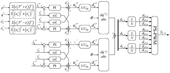
Figure 2.
Block diagram of voltage feedforward current decoupling control during grid unbalance.
When the grid voltage is unbalanced, the three-phase output power of the system will differ, which in turn leads to an imbalance in the SOC of the three-phase battery packs of the cascaded PCS. The zero-sequence voltage injection method is adopted to alter the inter-phase power flow, and the injected zero-sequence voltage u0 is defined as:
In the formula, U0 is the effective value of the zero-sequence voltage; θ0 is the initial phase angle of the zero-sequence voltage.
To ensure the consistency of its three-phase output power, the three-phase output power can be expressed as:
In the formula, Ua, Ub, and Uc are the effective values of the grid-side voltages; Ia, Ib, and Ic are the effective values of the grid-side currents; θa is the initial phase angle of the grid-side phase-a voltage; and φia is the initial phase angle of the grid-side phase-a current.
Thus, the effective value, U0, and phase angle, θ0, of the injected zero-sequence voltage can be obtained as shown in Equation (6), and the coefficient, τ, can be obtained as shown in Equation (7).
2.2. SOC Balancing Control
To facilitate the analysis of the SOC balancing principle of the cascaded energy storage converter, the definitions of the SOC average value of the battery packs of each phase power unit and the SOC average value of the battery packs of all power units are introduced. Then, the SOC unbalance degree, ∆SOCi, of the battery packs of each phase in the cascaded PCS can be defined as:
In the formula, SOCavg denotes the average SOC value of the battery systems of all power units in the PCS, and SOCi denotes the average SOC value of the battery systems of the power units for each phase in the PCS. The objective of the inter-phase SOC balancing control is ∆SOCi = 0. According to the Clark transformation, the power remains unchanged before and after the coordinate transformation. Therefore, an equal-power transformation is performed on the three-phase inter-phase unbalance degrees, ΔSOCa, ΔSOCb, ΔSOCc, which are converted to the αβ two-phase stationary reference frame [7].
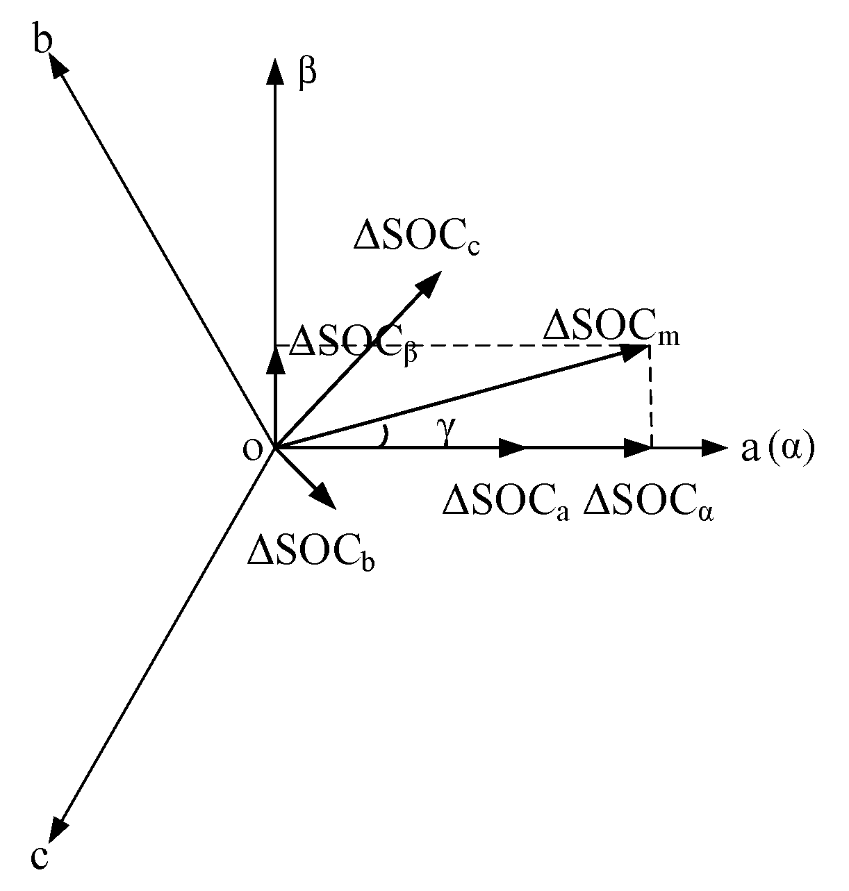
According to Figure 3, the vector amplitude of ΔSOCm and the included angle, γ, between the ΔSOCm vector and the α-axis are:
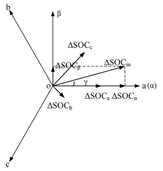
Figure 3.
Vector decomposition diagram of ΔSOCm.
Let the expression of the zero-sequence voltage component injected for the inter-phase SOC balancing control of the cascaded PCS be:
At this point, the output active power is:
Thus, the expressions for the regulating power required by each phase can be obtained as:
In the formula, is the inter-phase SOC balancing coefficient.
Taking phase a as an example for analysis, the amplitude and phase of the zero-sequence voltage can be derived as:
2.3. Fault-Tolerant Control
To ensure the stable operation of the battery energy storage system, fault-tolerant control is usually adopted to maintain the consistency of its three-phase output voltage without affecting the SOC of the battery [5].
The AC-side output voltages of the power units in the three phases can be expressed as:
In the formula, m is the modulation index.
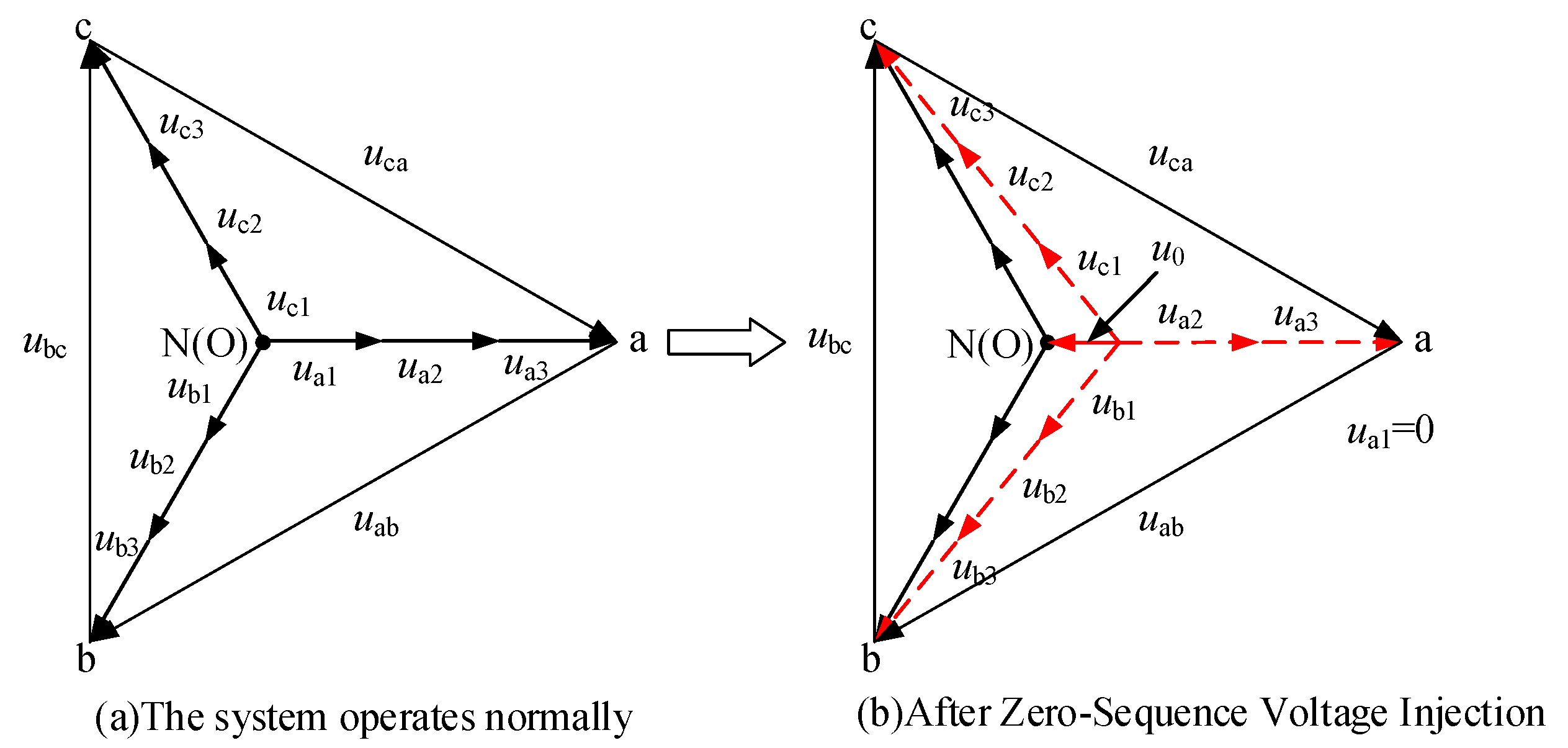
Assume that the SOC of the battery units and the DC-side voltages are consistent before a fault occurs. Taking phase a as an example, when the first power unit malfunctions, the zero-sequence voltage injection method is adopted to shift the neutral point potential of the system, thereby ensuring that the output line voltages of the system remain unchanged and the output power of each power unit is equal, as illustrated in Figure 4.
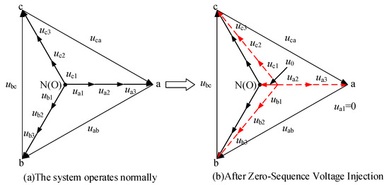
Figure 4.
Neutral point offset phase diagram. (a) The system operates normally, with black arrows representing the phase voltage vectors of the system. (b) After zero-sequence voltage injection, the red arrows represent the adjusted phase voltage vectors, and the black arrows represent the original phase voltage vectors for comparison.
Let the expression of the injected zero-sequence voltage be:
It can be obtained that the output voltage of each unit in each phase of the cascaded PCS at this point is:
At this point, the output active power of each power unit is:
To ensure the SOC balance of the cascaded PCS, except for the faulty unit, the output power of each phase should be equal.
From Equations (17) and (18), the amplitude and phase of the zero-sequence voltage are derived as:
When a fault occurs in phase b or phase c, the zero-sequence voltage component superimposed on each phase by fault-tolerant control can be derived by the same token. After zero-sequence voltage injection, the modulation waveform is reconfigured to compensate for the faulty unit. Consequently, the modulation index of the affected phase increases to fully utilize the remaining voltage margin.
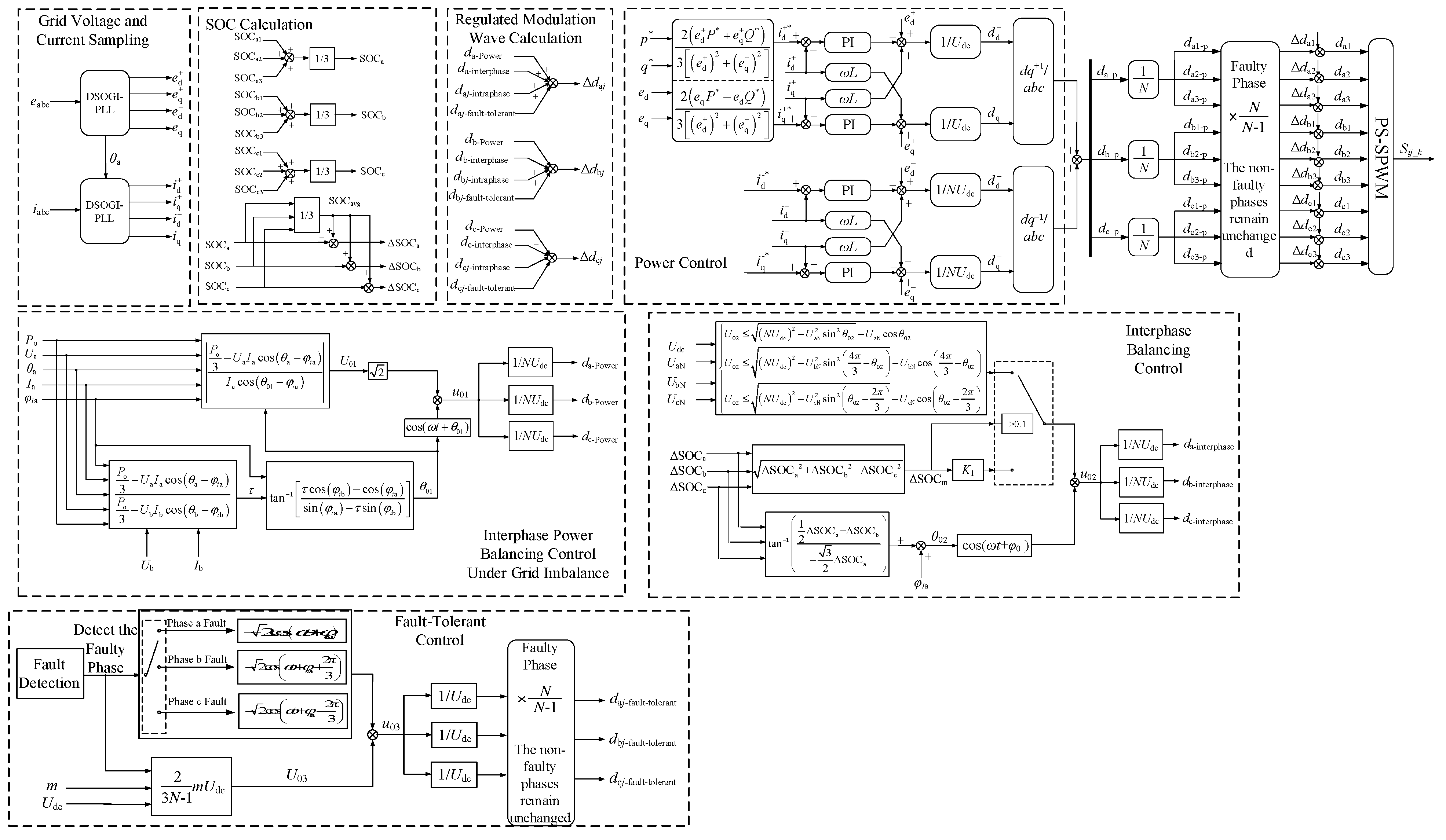
Based on the aforementioned system-level power control under grid voltage unbalance, inter-phase SOC balancing control with maximum zero-sequence voltage injection, and fault-tolerant control, the overall control block diagram of the cascaded PCS shown in Figure A1 can be obtained.
In the figure, the cascaded PCS implements system-level power control based on the grid voltage phase, amplitude, frequency, three-phase inductor current, and active and reactive power command values obtained by the phase-locked loop (PLL). The inter-phase SOC status is monitored using the battery system status information acquired from the battery management system (BMS). Meanwhile, by integrating the fault information of the H-bridge modules, the SOC balancing and fault-tolerant control modulated wave, Δdij, is superimposed on the modulated wave, dij-p, of the power control layer, thereby ensuring the safe and stable operation of the system.
Although the zero-sequence voltage injection method can effectively regulate inter-phase power distribution and enable SOC balancing and fault-tolerant control, its regulation capability is fundamentally constrained by the modulation limits of cascaded H-bridge cells. When the required zero-sequence voltage approaches its maximum allowable value, further improvement in SOC balancing speed becomes impossible, particularly under severe grid voltage unbalance or module fault conditions. This limitation motivates the introduction of third harmonic injection, which aims to expand the available modulation margin and enhance the overall balancing capability of the cascaded PCS, as discussed in the following section.
3. Unified Power Balance Control Strategy Based on Third Harmonic Injection
As discussed in Section 2, the effectiveness of zero-sequence voltage-based balancing control is restricted by the limited modulation margin of cascaded H-bridge converters. To overcome this limitation, this section introduces a unified power balancing strategy based on third harmonic injection. By injecting a properly designed third harmonic component into the output voltage, the peak value of the modulation waveform is reduced, thereby expanding the allowable zero-sequence voltage injection range without altering the fundamental power output. This section presents the analytical derivation of the extended zero-sequence voltage constraints, followed by the design methodology of the proposed unified control strategy.
To overcome the limited regulation range of conventional zero-sequence voltage injection, this section introduces a unified balancing control strategy based on third harmonic injection. By expanding the injection range, the effectiveness of power control, SOC balance control, and fault-tolerant control is ensured, thus guaranteeing the normal operation of the cascaded energy storage system [20]. For this purpose, the zero-sequence voltage power of the unified power balance strategy can be derived as:
In the formula, ΔPk1 is the power required by each phase under grid voltage unbalance, which can be expressed as follows:
ΔPk2 is the power required by each phase for inter-phase SOC balancing, as shown in Equation (22).
ΔPk3 is the power required by each phase when the a1 module malfunctions.
Solving Equation (20) yields:
The output voltage after zero-sequence voltage injection shall not exceed the DC-side voltage, from which the injection range of the zero-sequence voltage can be derived [7].
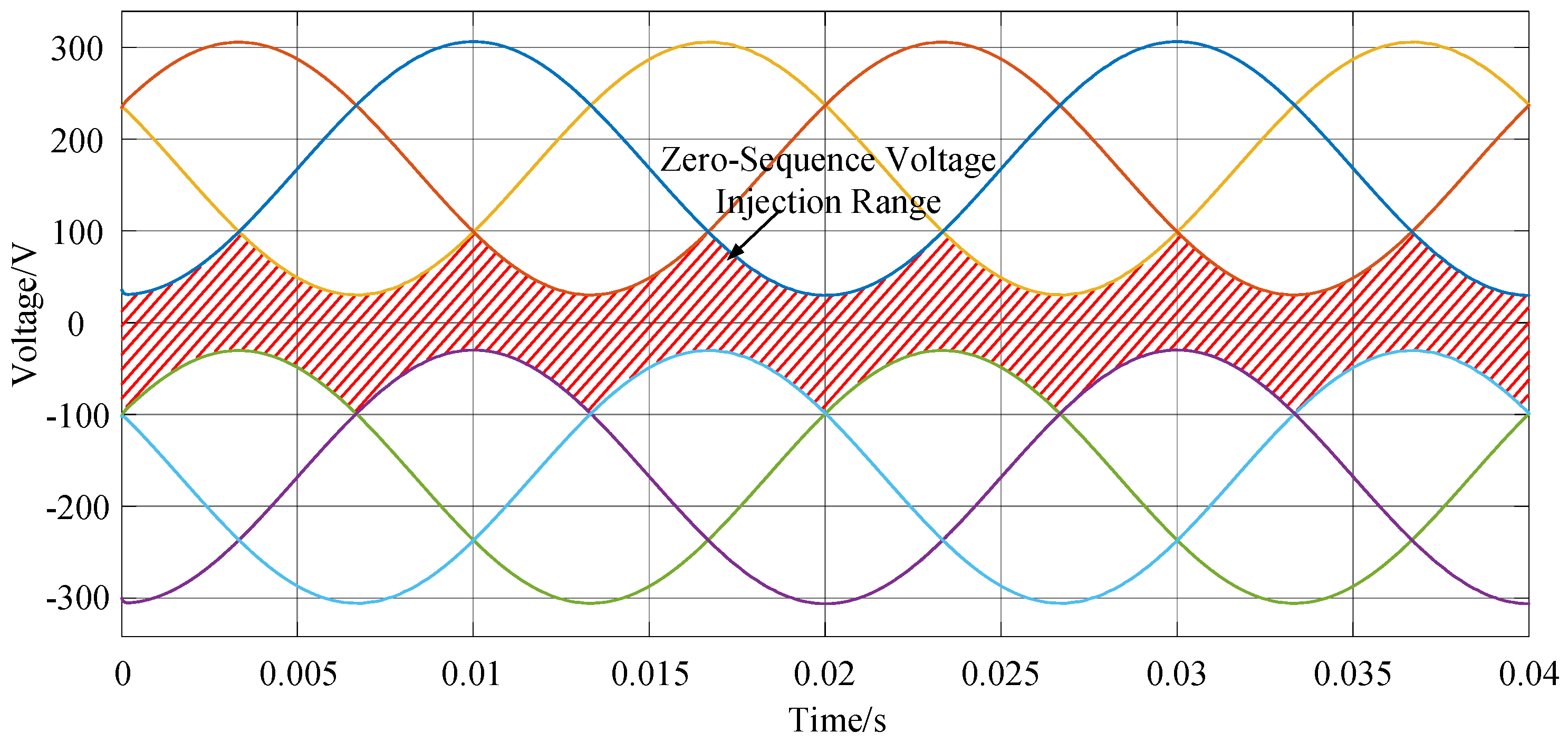
The zero-sequence voltage range shown in Figure 5 can be derived from the above equation. The blue, orange, and green curves represent the phase voltage waveforms of phase A, B, and C in the cascaded power conversion system (PCS), respectively. The red shaded area denotes the allowable injection range of the zero-sequence voltage u02, which is defined by Equation (25).
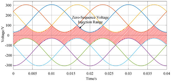
Figure 5.
Zero-sequence voltage injection range.
To ensure the normal operation of the PCS, when the amplitude of the zero-sequence voltage exceeds the injection range, it is necessary to reduce the amplitude of the zero-sequence voltage by lowering the inter-phase SOC balancing power, and then increase the SOC balancing power again after the grid returns to normal or the fault is eliminated.
When the zero-sequence voltage regulation capability of the cascaded PCS is insufficient, injecting the third harmonic into the output voltage can reduce the modulation index of the output modulated wave without changing the output power, thereby improving the voltage utilization rate of the DC side.
The three-phase output voltage after zero-sequence voltage injection can be defined as:
The injected third harmonic voltage component is expressed as:
In the formula, , βx is the phase angle after zero-sequence voltage injection [17,18].
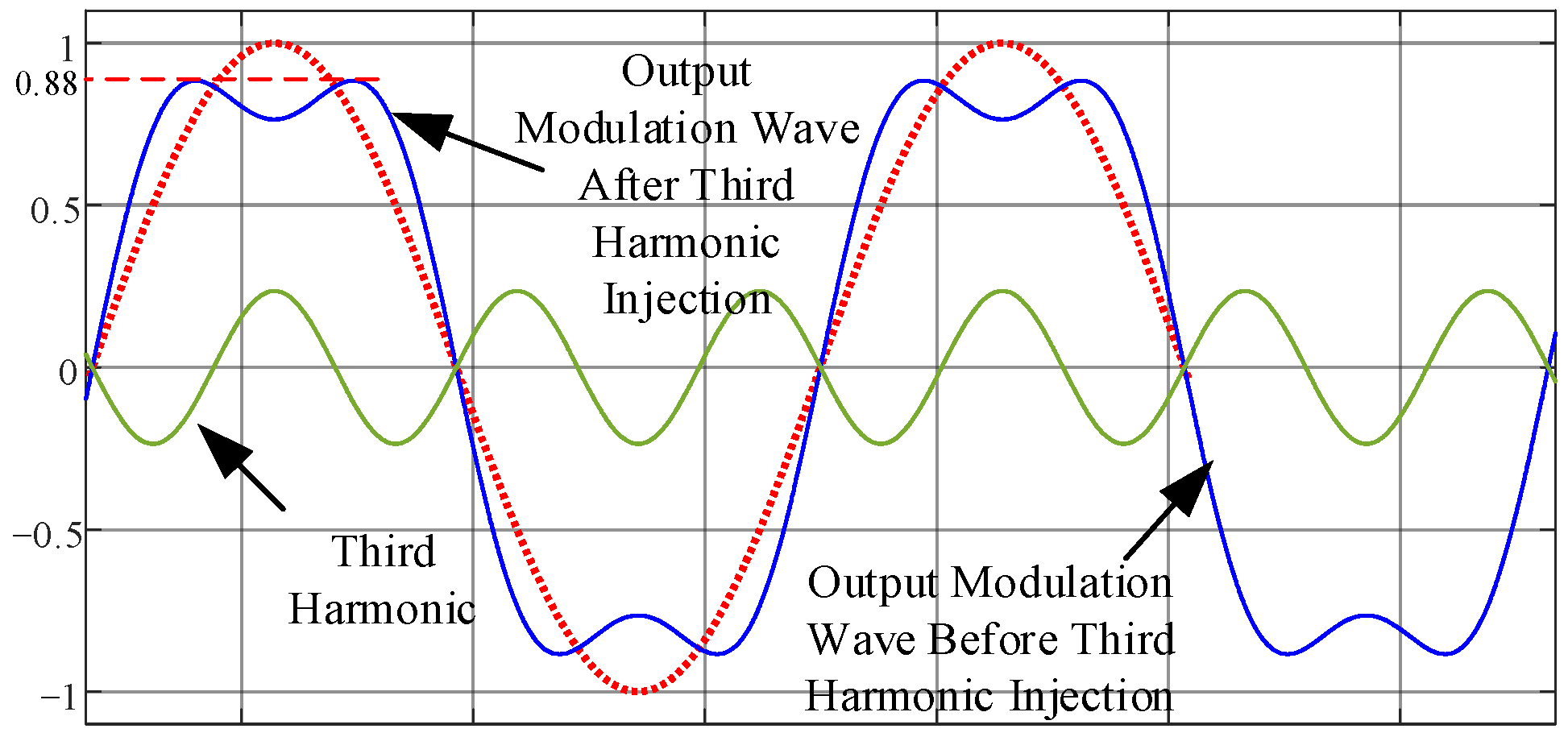
Through Equations (26) and (27), a comparison diagram of the output waveforms before and after injecting the third harmonic with an amplitude of 1/6 can be obtained. Taking the maximum output voltage of phase a as an example, it is shown in Figure 6.
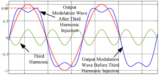
Figure 6.
Comparison of output waveforms before and after third harmonic injection.
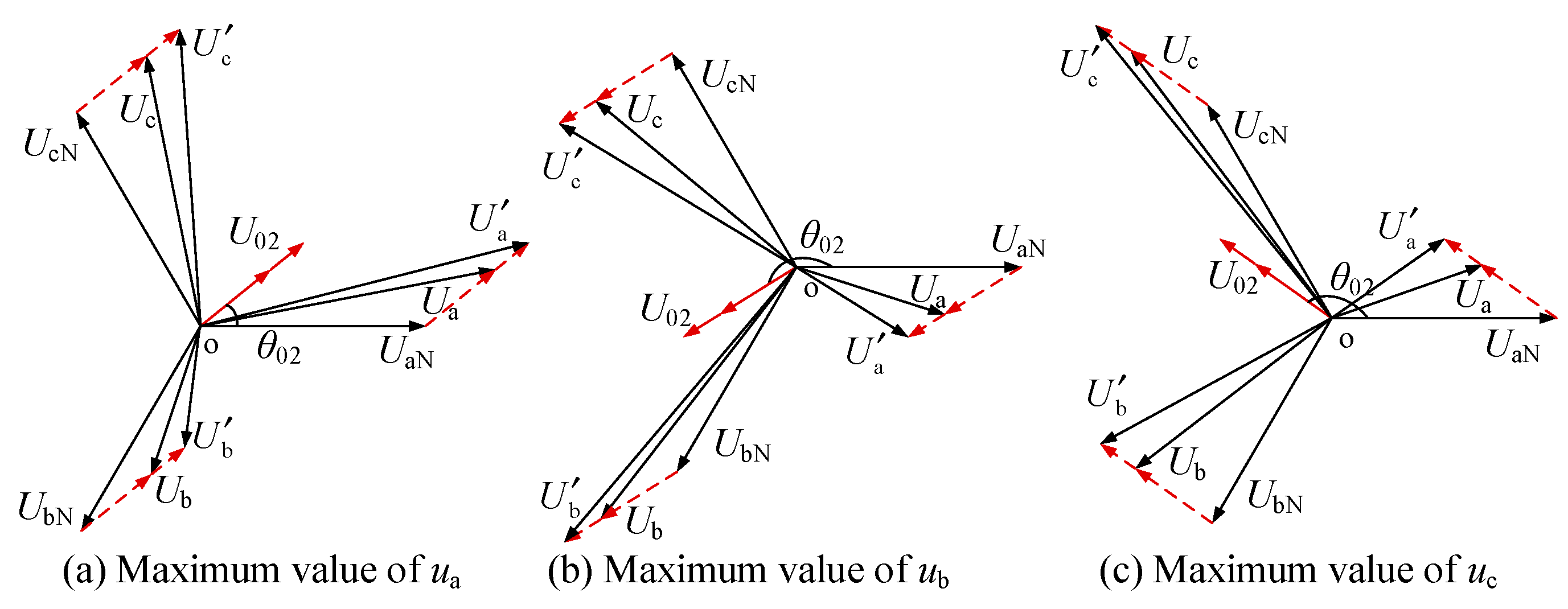
In Figure 6, the fundamental wave range of the modulated wave can be expanded by introducing the third harmonic, increasing the maximum modulation index to 1.15. To determine the maximum value of the zero-sequence voltage after the third harmonic injection, a detailed analysis is conducted on the output voltage of the inverter side. The phasor diagram of the output voltage of the cascaded PCS is shown in Figure 7 [21].
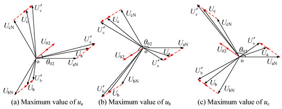
Figure 7.
Phase diagram of PCS output voltage after considering third harmonic.
From the above process, the constraint conditions for zero-sequence voltage injection can be obtained as:
The zero-sequence voltage range after third harmonic injection, from which it can be clearly seen that the zero-sequence voltage range is significantly expanded after the third harmonic is injected is shown in Figure 8. The sinusoidal curves represent the original voltage waveforms, while the saddle-shaped curves are the waveforms after the injection of the third harmonic. The red shaded area denotes the zero-sequence voltage injection range, and the orange shaded area represents the expanded zero-sequence voltage injection range.
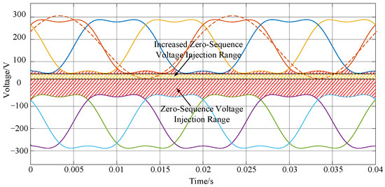
Figure 8.
Zero-sequence voltage range after third harmonic injection.
4. Verification of the Control Strategy for Cascaded PCSs
To verify the equalization control strategy proposed in this paper, a simulation model of the cascaded PCS is built in MATLAB 2023b. A general battery model in the Simscape module is adopted for the DC-side battery system. The battery capacity is intentionally scaled to 0.01 Ah for simulation acceleration purposes. This scaling preserves the proportional relationship between power and SOC dynamics while significantly reducing simulation time. The control strategy itself is independent of the absolute battery capacity. The detailed simulation parameters are shown in Table 1.

Table 1.
Cascade type PCS simulation parameters.
4.1. System-Level Power Control Simulation Verification
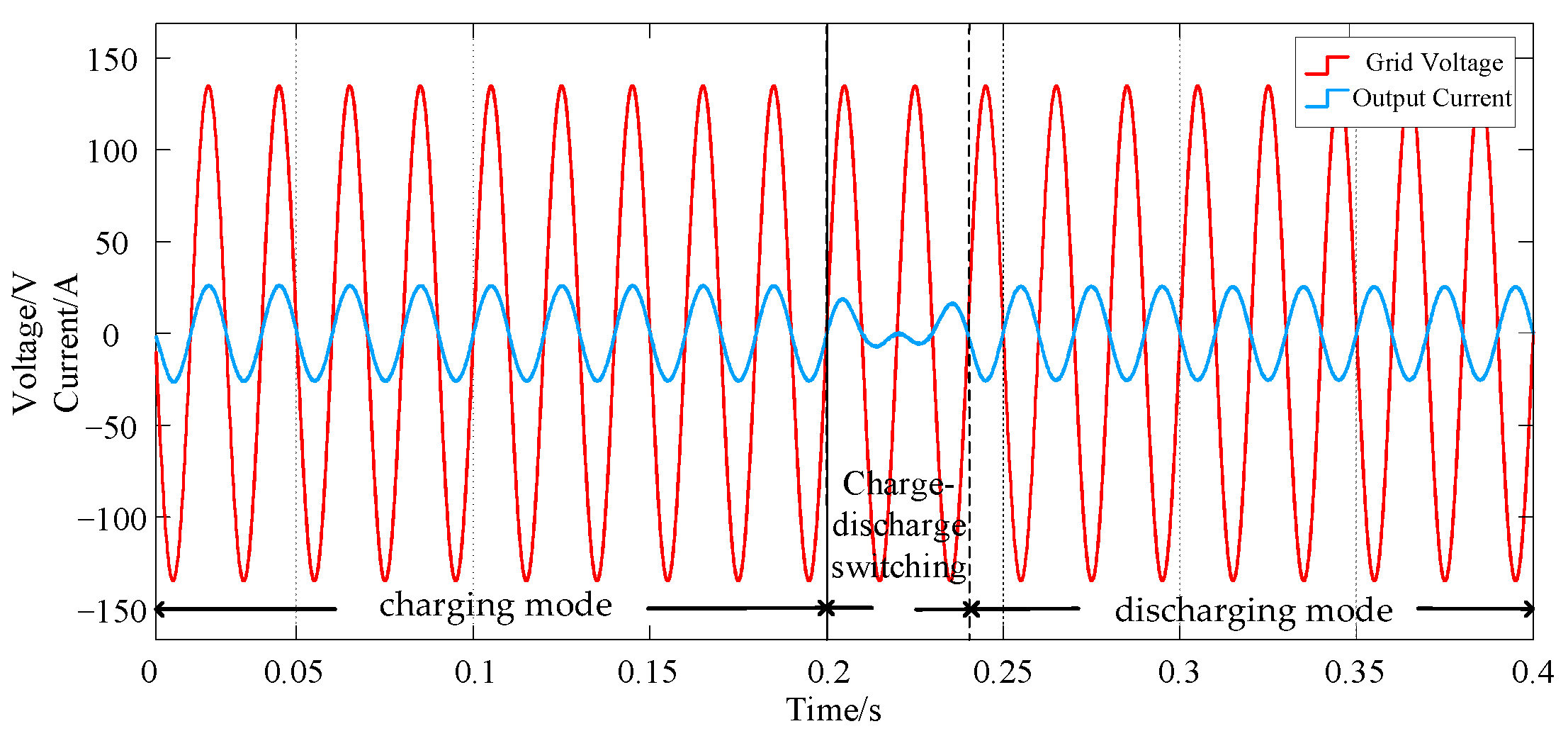
System-level power control can realize basic functions such as charging, discharging, and charge/discharge switching under a given power output. Figure 9 shows the grid voltage and output current waveforms of the cascaded PCS under the charge–discharge switching mode of phase-a. In the period of 0–0.2 s, the PCS operates in charging mode, and the grid voltage is in phase with the PCS output current. At 0.2 s, the PCS receives the charge–discharge switching command, and the system completes the switching within 40 ms with no impact or overshoot during the switching process. In the period of 0.24–0.4 s, the PCS operates in discharging mode, where the grid voltage is out of phase with the PCS output current.
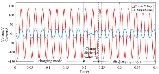
Figure 9.
Cascaded PCS charge/discharge switching simulation waveforms.
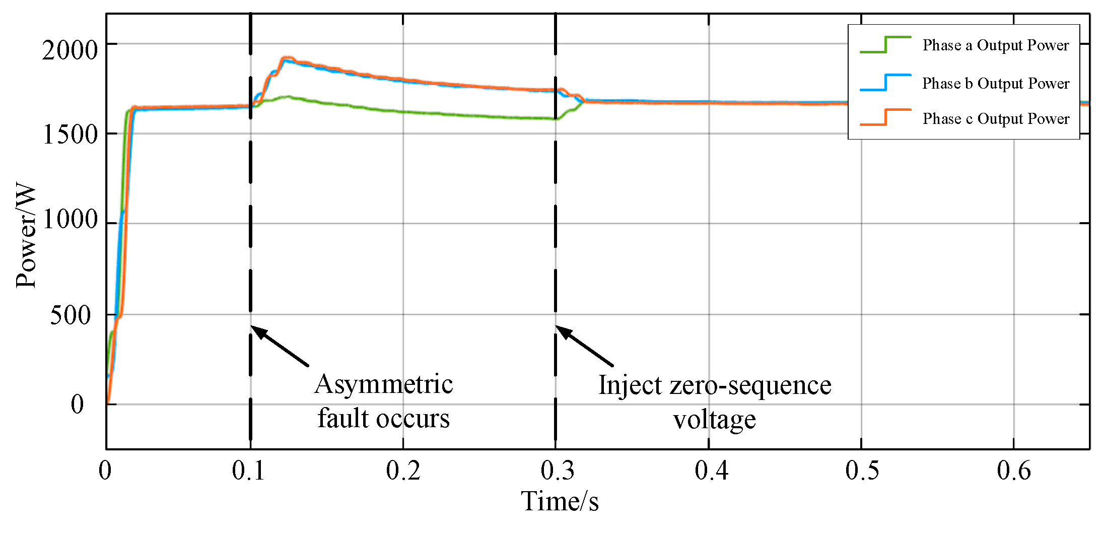
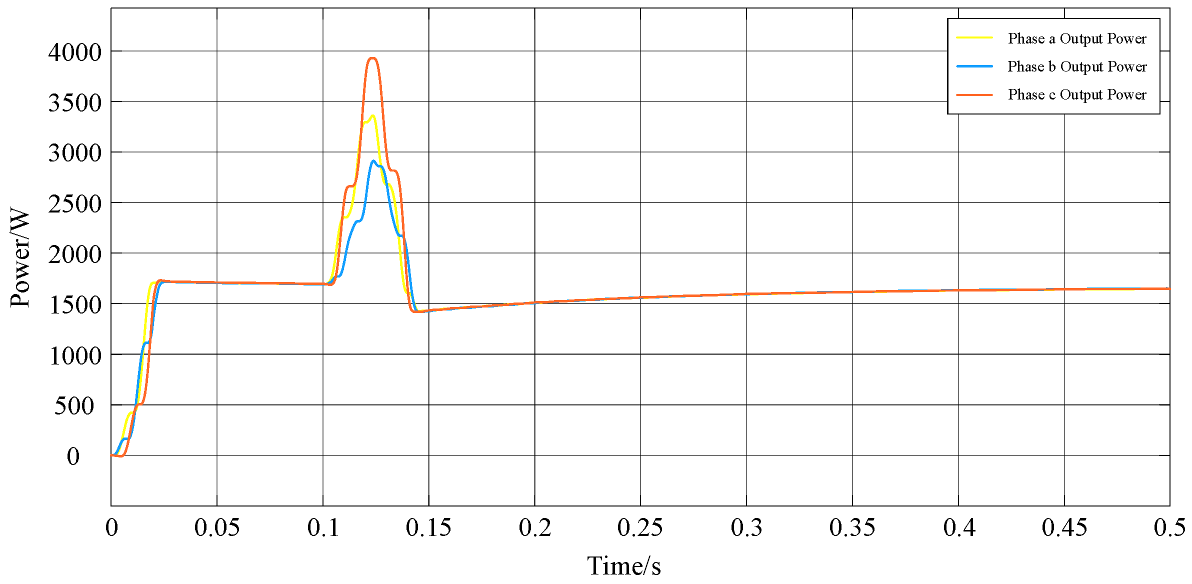
Figure 10 shows the three-phase output power waveform diagram of the cascaded PCS. An asymmetric fault occurs in the system at 0.1 s, resulting in unbalanced output power among the three phases. Zero-sequence voltage is injected at 0.3 s, and the three-phase power of the PCS gradually tends to a balanced state. It can be seen from the waveform diagram that the zero-sequence voltage injection method can effectively regulate the output power of the PCS and prevent SOC imbalance.
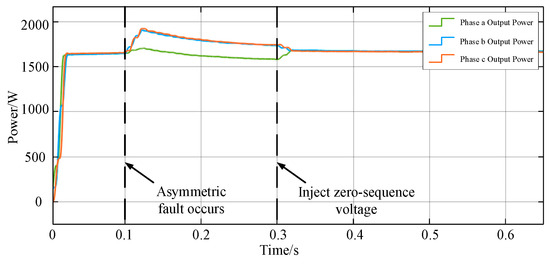
Figure 10.
Cascaded PCS three-phase output power waveforms.
4.2. SOC Balancing Control Simulation Verification
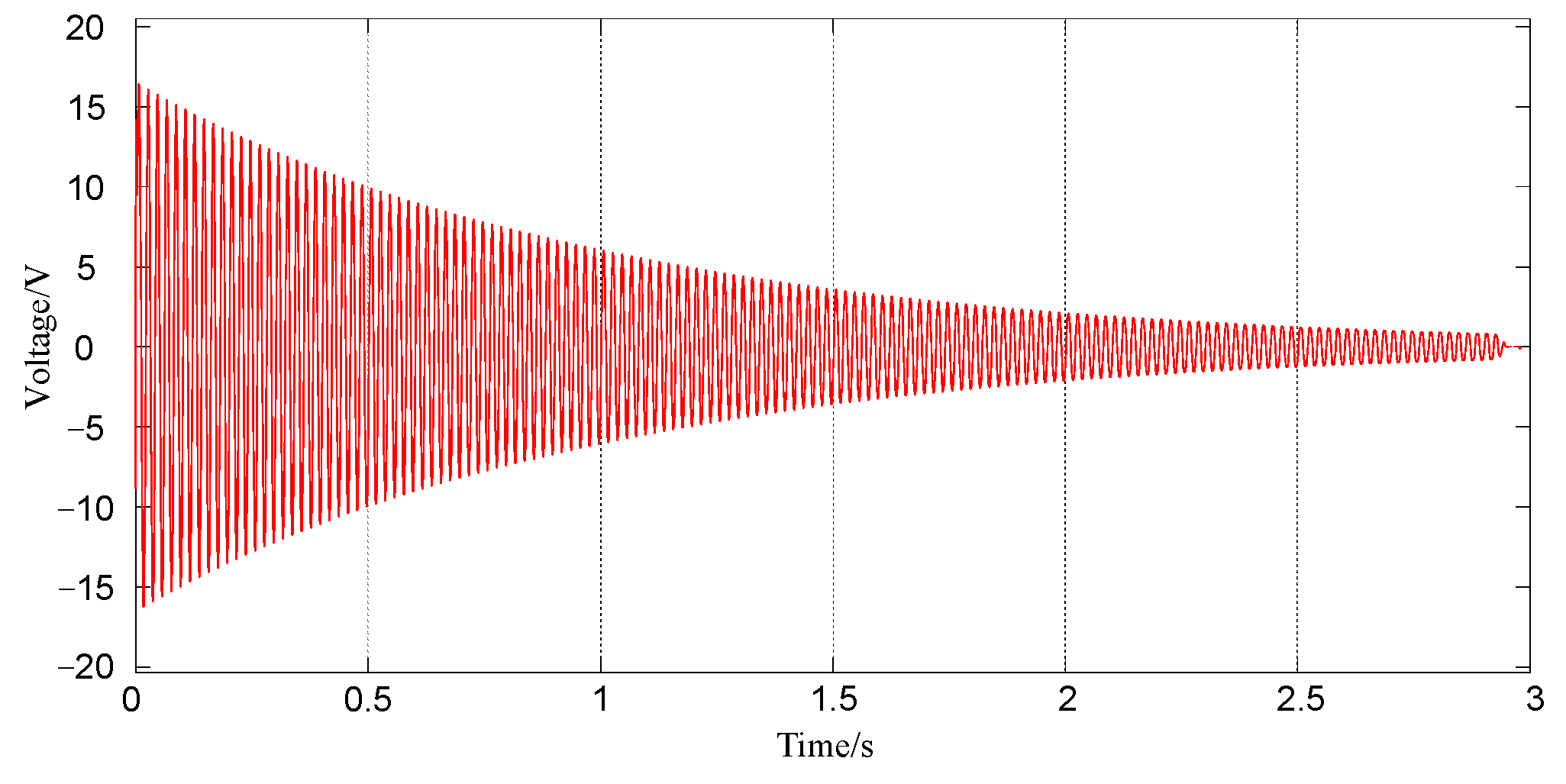
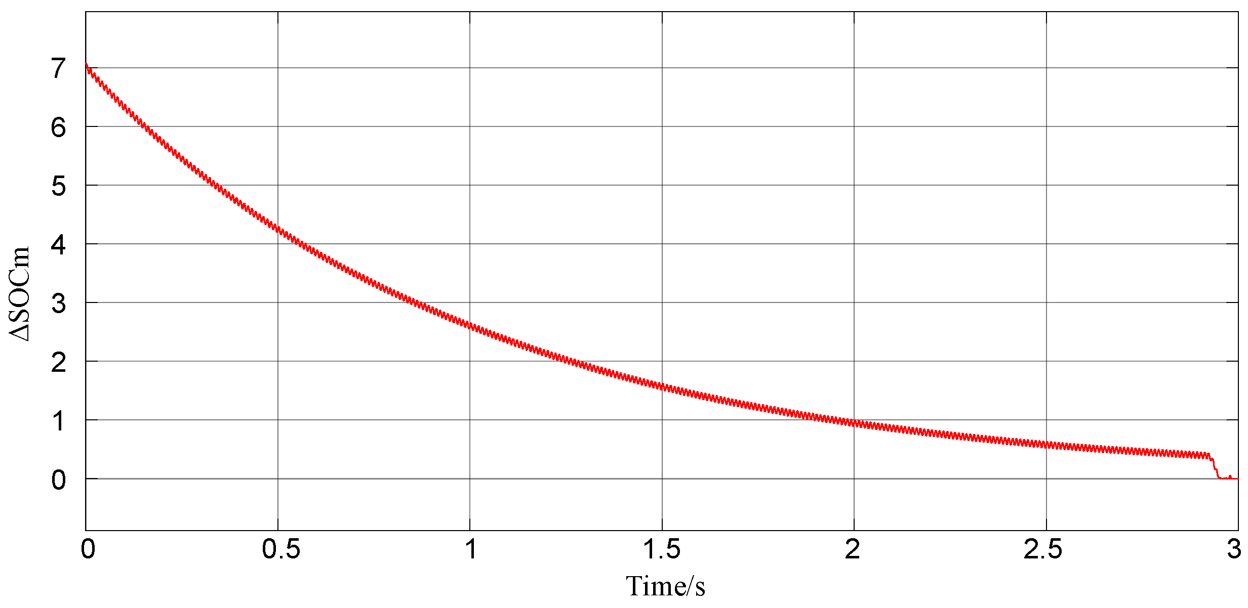
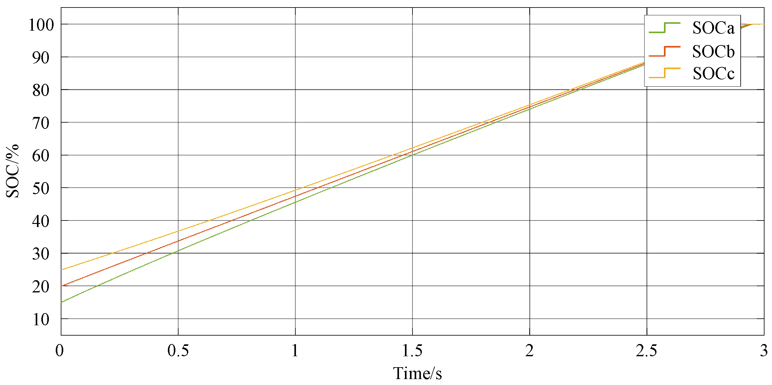
To verify the inter-phase SOC balancing control strategy of the cascaded energy storage converter, a simulation was conducted under the charging state. The initial SOC values of phases a, b, and c were set to 15%, 20%, and 25% respectively, and the inter-phase balancing coefficient, Λ, was set to 4, as shown in Figure 11, Figure 12 and Figure 13. With the injection of zero-sequence voltage, the inter-phase SOC imbalance degree, ΔSOC, of the system gradually decreased until the SOCs of all battery modules among the three phases tended to be consistent. It can be seen from Figure 13 that the zero-sequence voltage injection method can realize the inter-phase SOC balancing control by adjusting the amplitude of the injected zero-sequence voltage, which verifies the effectiveness of this control strategy. In this paper, the SOC convergence time is defined as the time required for the inter-phase imbalance index, ΔSOCm, to decrease below 1% of the average SOC value and remain within this band for at least one fundamental cycle.
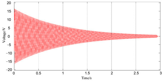
Figure 11.
Zero-sequence voltage u0 waveform.
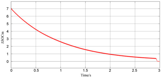
Figure 12.
Three-phase SOC unbalance ΔSOCm waveforms.
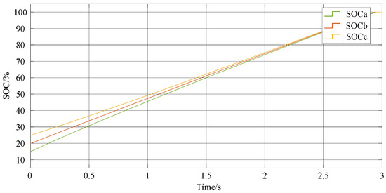
Figure 13.
Three-phase SOC waveform.
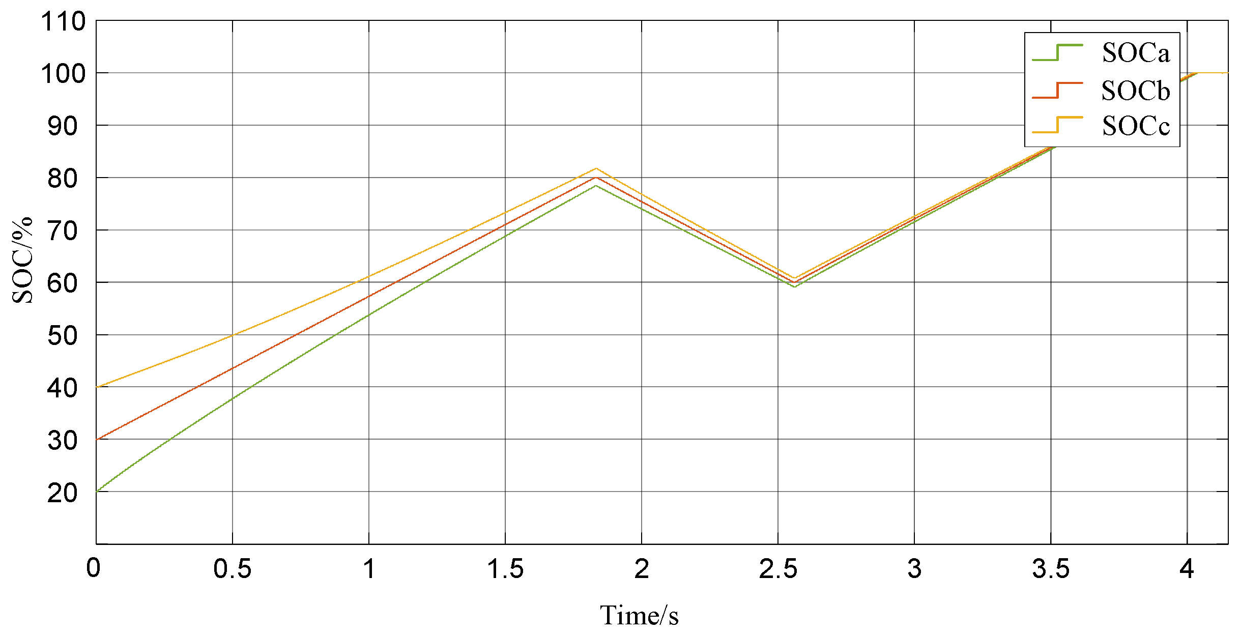
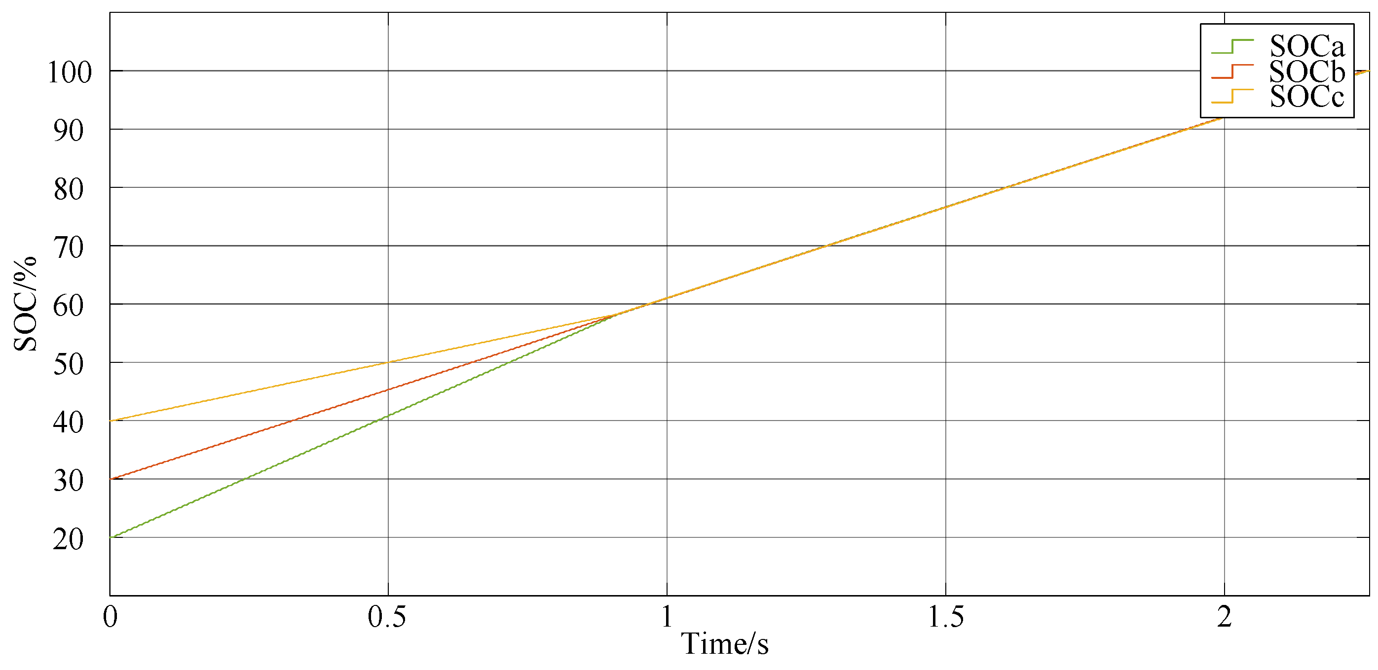
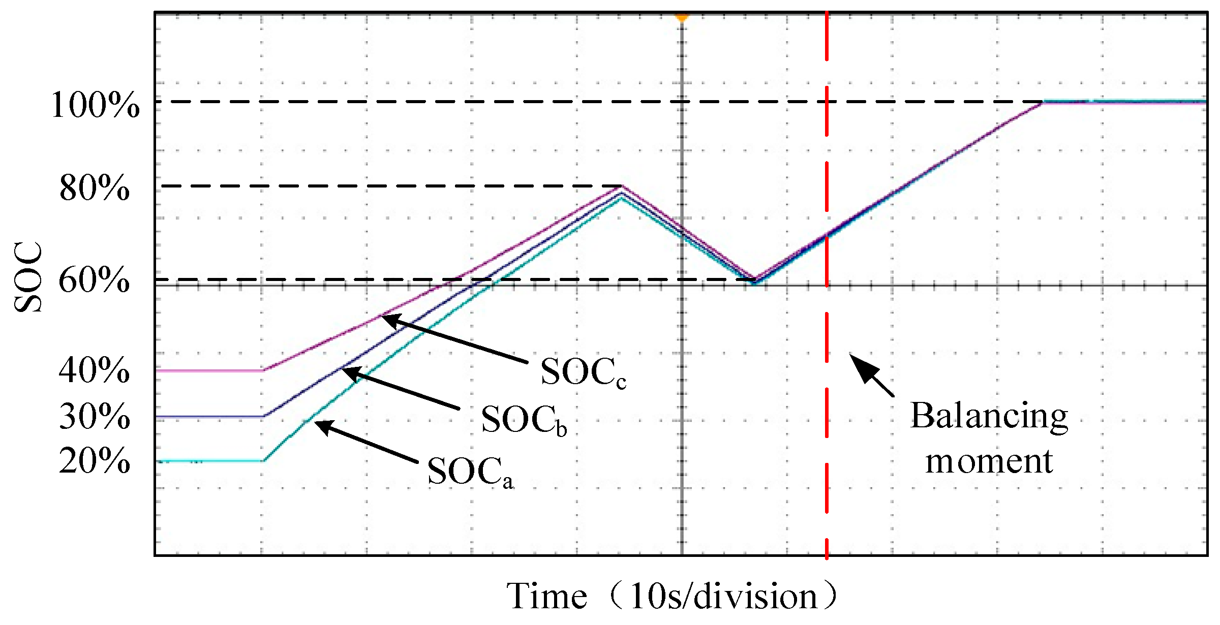
The SOC values of phases a, b, and c are set to 20%, 30%, and 40% respectively, with the inter-phase balancing coefficient, Λ, set to 4, to simulate the SOC balancing control under the condition of large SOC differences among the three phases. In this case, it is difficult to achieve the SOC balancing within a single charge/discharge cycle. Therefore, multiple cycles of charge/discharge are performed within the SOC range of 60% to 80% to realize inter-phase SOC balancing, as shown in Figure 14.
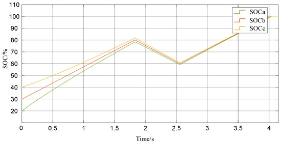
Figure 14.
Phase-to-phase SOC equalized three-phase SOC waveform for larger ΔSOCm.
4.3. Fault-Tolerant Control Simulation Verification
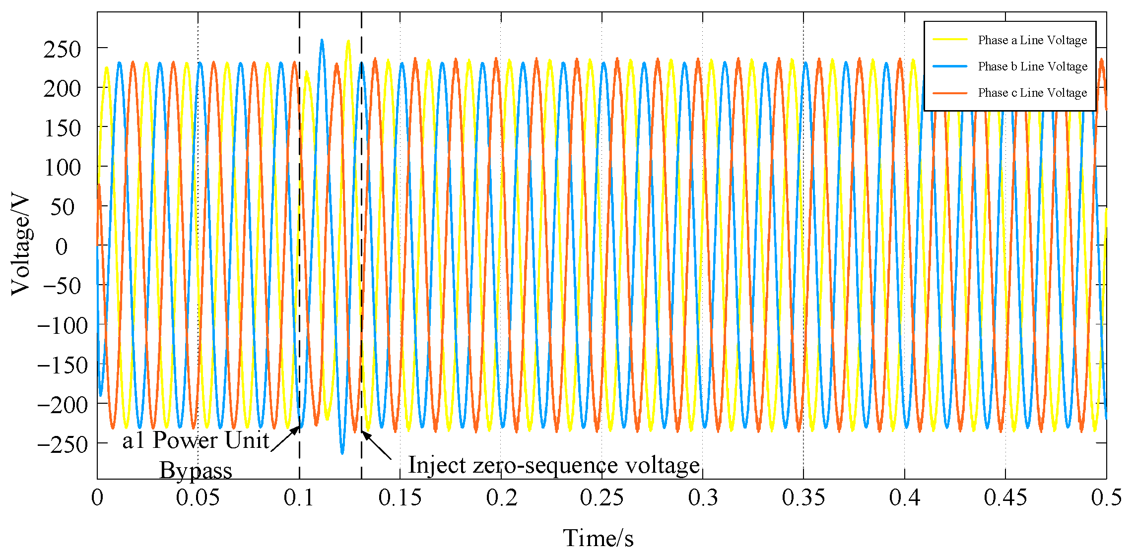
Taking phase-a of the PCS as an example to verify the fault-tolerant control strategy, the initial SOC values of each battery module are set to be the same. When the first power module fails, the module is bypassed, and zero-sequence voltage is injected for fault-tolerant control. Figure 15 and Figure 16 show the three-phase output power waveforms. At 0.1 s, the first power unit of phase-a fails, and the a1 power unit is bypassed. The DC-side current drops to zero, leading to the imbalance of three-phase line voltage and output power. At 0.12 s, zero-sequence voltage is injected. By regulating the power flow among the three phases, the three-phase line voltage gradually balances. Figure 16 indicates that the zero-sequence voltage injection strategy can achieve fault-tolerant control, ensure the consistency of three-phase output power when the system fails, and verify the effectiveness of this control strategy.
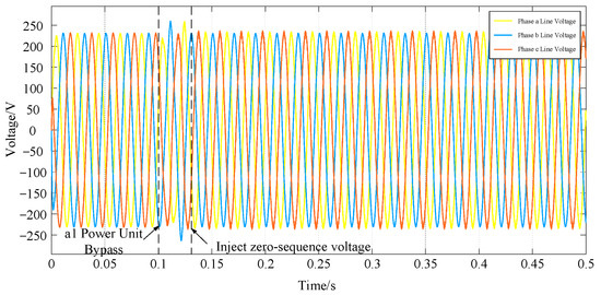
Figure 15.
Three-phase line voltage waveform.
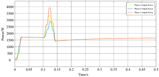
Figure 16.
Three-phase output power waveform.
4.4. Simulation Verification of Unified Power-Balancing Control Based on Third Harmonic Injection
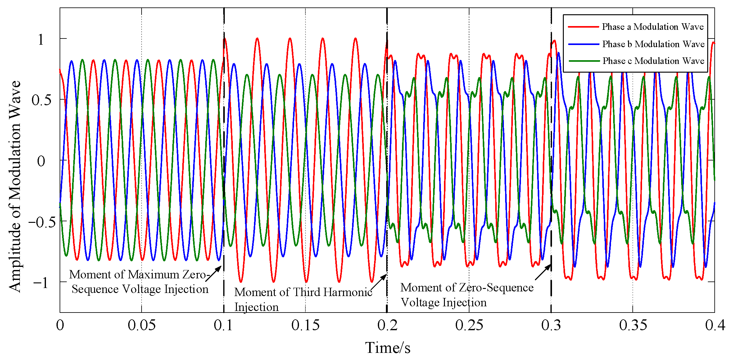
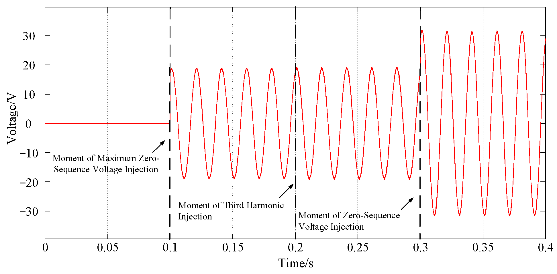
To verify the unified power-balancing strategy for cascaded energy storage converters based on third harmonic injection, the maximum zero-sequence voltage injection method is adopted to simulate the condition where the modulated wave reaches amplitude limiting, and then the third harmonic is injected to expand the zero-sequence voltage injection range. As shown in Figure 17 and Figure 18, the maximum zero-sequence voltage is injected at 0.1 s, at which point the modulated wave of phase-a hits the amplitude limit. To extend the zero-sequence voltage injection range, the third harmonic is injected into the system at 0.2 s, leading to a reduction in the modulation index, and, subsequently, zero-sequence voltage can be injected into the system at 0.3 s.
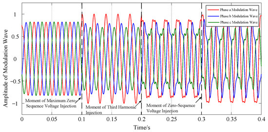
Figure 17.
Three-phase modulated waveform.
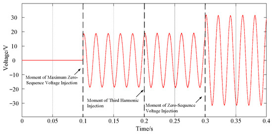
Figure 18.
Zero-sequence voltage waveform.
The inter-phase SOC waveforms are shown in Figure 19. Compared with the maximum zero-sequence voltage injection method, the balancing speed is nearly doubled, which verifies the effectiveness of this control strategy.
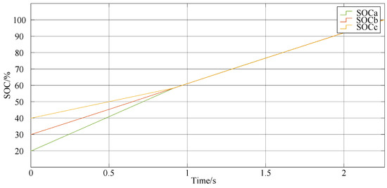
Figure 19.
Uniform power equalization three-phase SOC waveform based on third harmonic injection.
To clearly compare the performance differences between the proposed unified control strategy and existing mainstream SOC balancing control strategies, five core performance indicators including zero-sequence voltage range expansion rate and SOC convergence time reduction rate are selected. Combined with the research results of various studies and the simulation and experimental data of this paper, the Table 2 is constructed to intuitively present the numerical improvement advantages of the proposed strategy.
Table 2.
This work vs. prior art.
5. Hardware-in-the-Loop-Based Control Strategy Validation
5.1. Introduction to the Platform
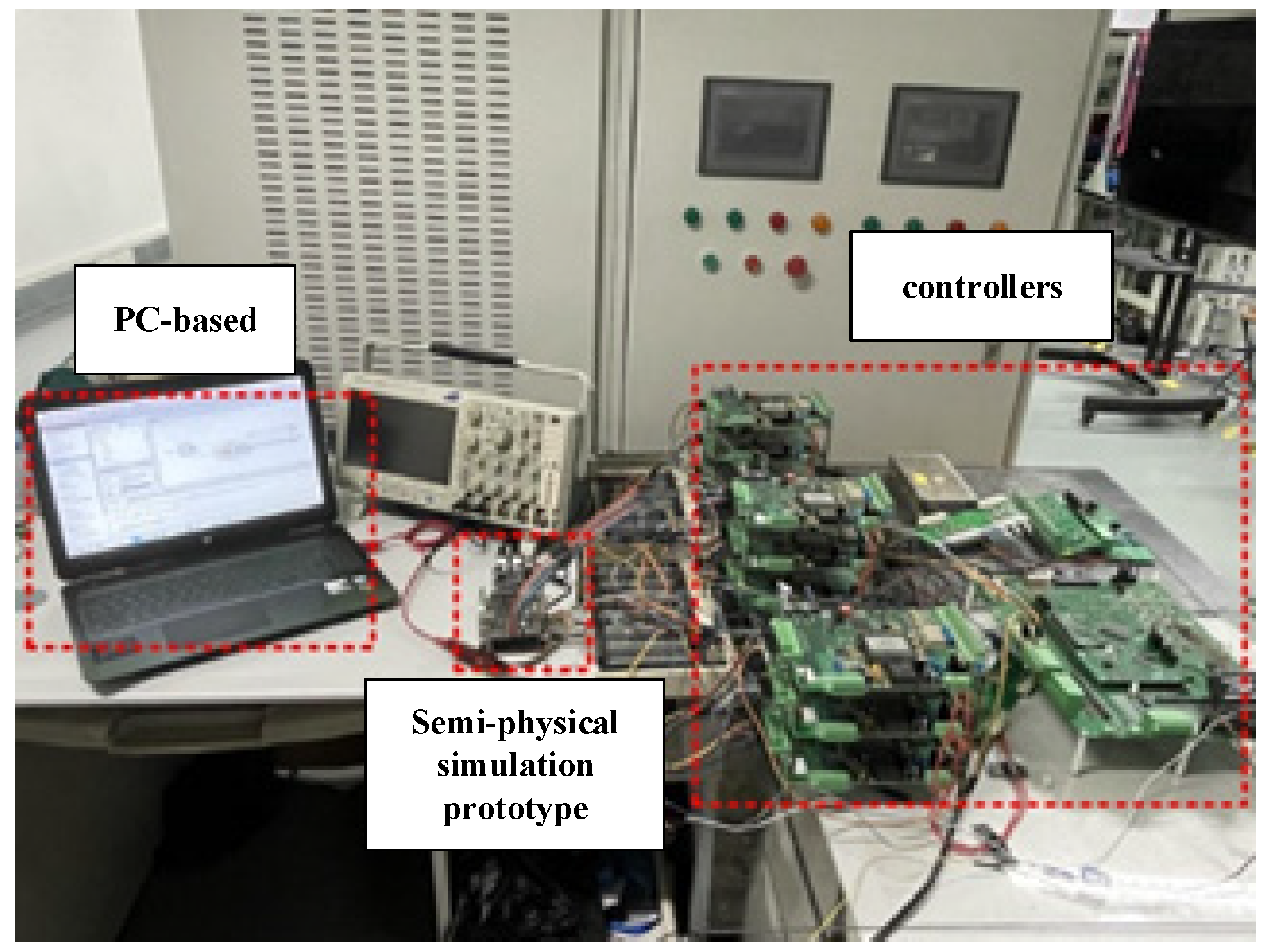
The hardware-in-the-loop (HIL) semi-physical simulation hardware platform for cascaded energy storage PCS is shown in Figure 20. The host computer is connected to the HIL simulator MT6016 which is manufactured by Modeling Tech. in Shanghai, China, via optical fiber, where the main circuit model of the cascaded energy storage PCS and the battery model are established. Sampled analog signals such as voltage and current are transmitted to the controller through an adapter board, and battery information such as SOC and temperature is transmitted via the RS485 serial port based on the Modbus protocol. The DSP implements system-level power, as well as SOC balancing and fault-tolerant control strategies based on the sampled data, generating the total control modulation wave of each power unit and outputting it to the FPGA. The FPGA generates PWM drive signals for power units using PS-SPWM, encodes them into high-frequency signals, and transmits them to the power unit controller via optical fiber. The CPLD decodes the signals into switching signals for each power unit, which are finally sent to the MT6016 simulator through the adapter board to achieve stable system operation.
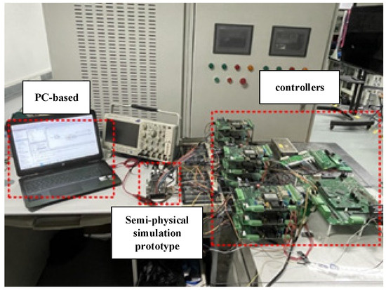
Figure 20.
Real-time simulation prototype platform.
5.2. Hardware-in-the-Loop Validation of Unified Power-Balancing Control Based on Third Harmonic Injection
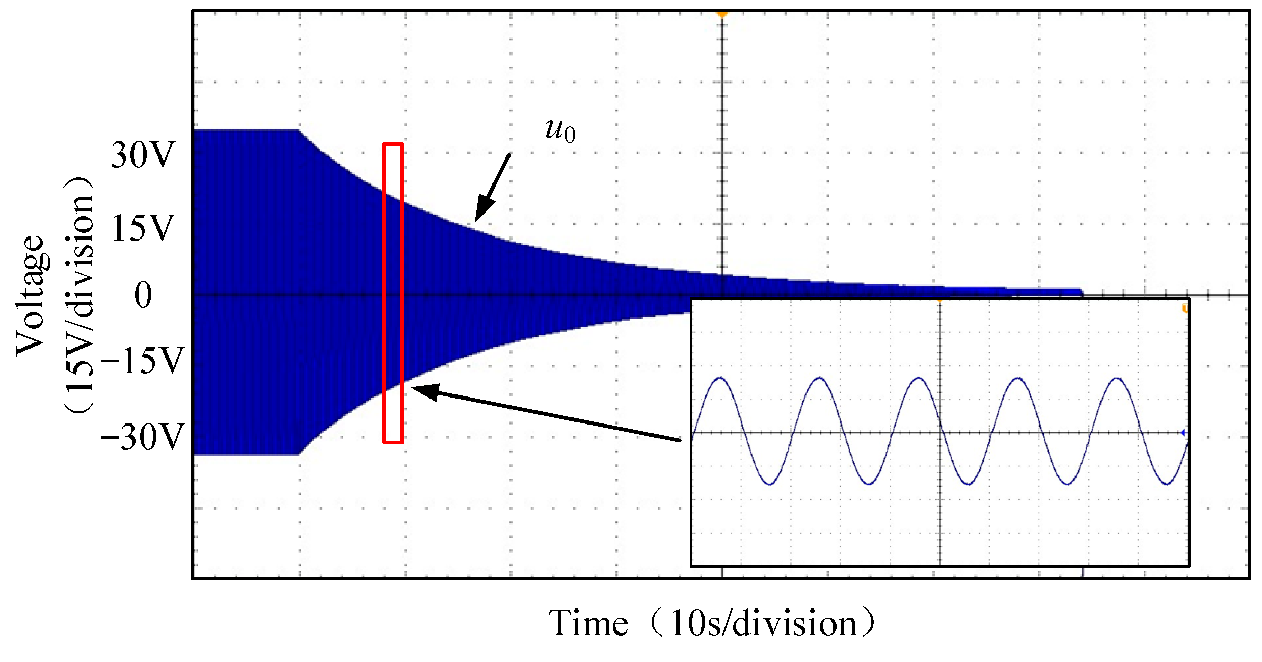
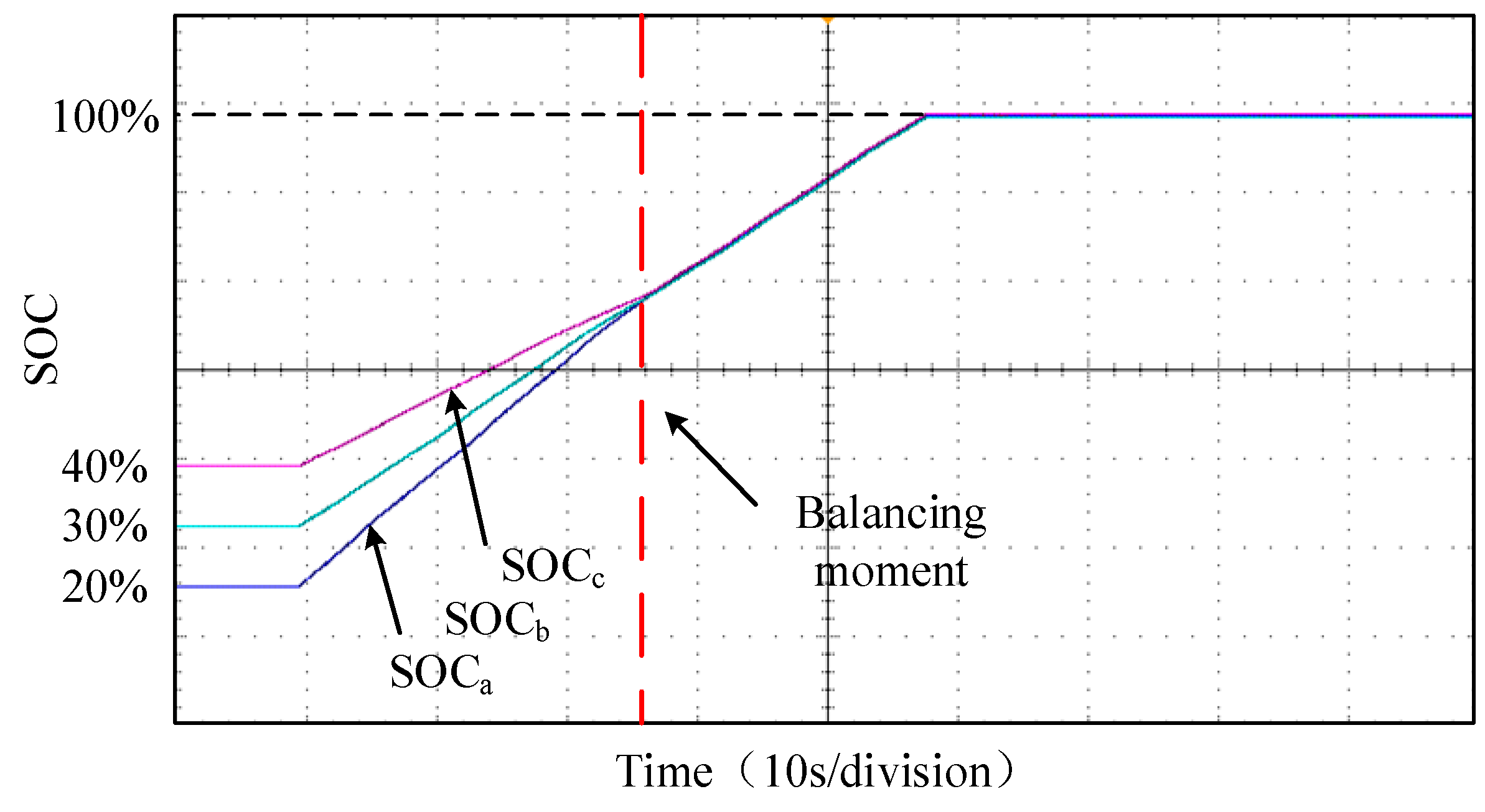
To verify the inter-phase SOC balancing control strategy of the cascaded PCS, taking the charging state as an example, the initial SOC values of phases a, b, and c are set to 20%, 30%, and 40% respectively, with the inter-phase balancing coefficient, Λ, being 4. Figure 21 shows the three-phase SOC waveform, and Figure 22 shows the zero-sequence voltage u0 waveform. At this time, the three-phase unbalance degree ΔSOCₘ of the cascaded PCS is relatively large, making it difficult to achieve SOC balancing within one charge/discharge cycle. SOC balancing between phases is realized through several cycles of charge/discharge in the SOC range of 60% to 80%.
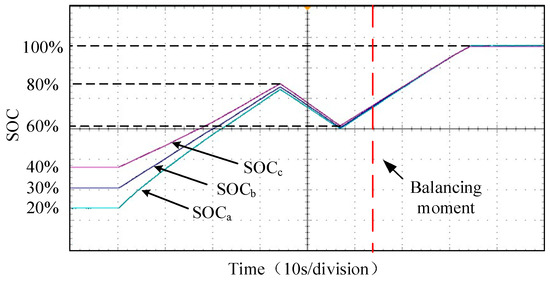
Figure 21.
Three-phase SOC waveform diagram.
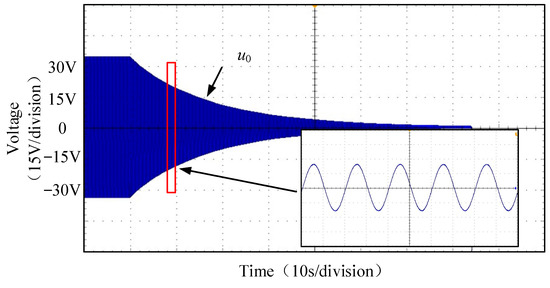
Figure 22.
Zero-sequence voltage u0 waveform diagram.
To verify the unified power-balancing control strategy based on third harmonic injection, the SOC values of phases a, b, and c are set to the same value. Compared with Figure 21, it can be concluded from Figure 23 that the maximum zero-sequence voltage injection method can achieve SOC balancing in a shorter time than the traditional zero-sequence voltage injection method, verifying the superiority of the proposed control strategy.
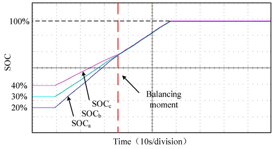
Figure 23.
Three-phase SOC waveform diagram.
6. Conclusions
This paper presented a unified balancing control strategy for cascaded power conversion systems (PCSs) based on third harmonic injection, aiming to address the inter-phase power imbalance, state-of-charge (SOC) divergence, and fault-tolerant operation within a single control framework.
First, the limitations of conventional zero-sequence voltage injection were analytically identified, showing that the achievable SOC balancing performance is fundamentally constrained by the modulation margin of cascaded H-bridge converters. Based on this analysis, the maximum allowable zero-sequence voltage injection range was derived, providing a clear theoretical boundary for traditional balancing strategies.
To overcome this limitation, third harmonic injection was introduced to expand the available modulation margin without altering the fundamental output power. The analytical derivation demonstrates that the maximum zero-sequence voltage injection range can be increased by approximately 35–40%, effectively enlarging the feasible regulation space for the inter-phase power redistribution. As a result, the proposed strategy enables stronger and faster SOC balancing under severe grid voltage unbalance and fault conditions.
Simulation and hardware-in-the-loop (HIL) results further validate the effectiveness of the proposed method. Compared with conventional zero-sequence voltage control, the SOC convergence time is reduced by nearly 50% under identical operating conditions, while maintaining stable three-phase power output and acceptable power quality. Moreover, the unified framework allows seamless coordination of the system-level power control, SOC balancing, and fault-tolerant operation, avoiding additional control loops or mode switching.
Overall, the proposed strategy represents a quantitative enhancement of existing zero-sequence-based balancing methods by integrating third harmonic injection into a unified control structure. Future work will focus on experimental validation using a laboratory-scale prototype, adaptive tuning of the third harmonic injection amplitude, and further investigation of its impact on harmonic distortion and long-term battery lifetime.
7. Discussion
Although the proposed unified balancing strategy significantly enhances the zero-sequence voltage regulation capability and accelerates the SOC convergence, several practical aspects deserve further discussion.
First, the expansion of modulation margin through third harmonic injection increases the available zero-sequence voltage range without introducing additional current components. However, excessive harmonic injection may increase voltage stress on semiconductor devices and slightly affect high-frequency switching ripple. Therefore, the amplitude of the injected third harmonic should be carefully limited to ensure long-term reliability.
Second, while the proposed strategy does not increase the RMS current, the redistribution of phase power may slightly modify battery cycling profiles among phases. Although this redistribution improves the SOC consistency, the long-term impact on battery aging requires further experimental investigation under real operating conditions.
Third, for systems with a larger number of cascaded modules or higher voltage levels, synchronization and communication delays among modules may influence dynamic balancing performance. Nevertheless, since the proposed strategy operates at the modulation level without introducing additional current loops, its scalability remains promising for medium-voltage applications.
Finally, practical implementation may be affected by the BMS measurement delays and communication latency. However, because the SOC balancing dynamics occurs at a relatively slow timescale compared to the switching frequency, these delays are not expected to compromise system stability.
Future work will focus on laboratory-scale experimental validation and adaptive tuning of the third harmonic injection coefficient under varying grid conditions.
Author Contributions
X.Z.: resources, supervision; J.C.: methodology, validation, writing; J.Z.: project administration, funding acquisition; T.W.: software, data curation; S.S.: conceptualization, investigation. All authors have read and agreed to the published version of the manuscript.
Funding
This research was funded by the Beijing Municipal Natural Science Foundation, grant number L242007 and the Yuxiu Innovation Project of North China University of Technology (NCUT) (Project No. 2024NCUTYXCX103).
Data Availability Statement
The original contributions presented in this study are included in the article. Further inquiries can be directed to the corresponding author.
Conflicts of Interest
Author Tianyu Wang was employed by Beijing Electric Power Company. Shoubin Sun was employed by State Grid Baiyin Power Supply Company. The remaining authors declare that the research was conducted in the absence of any commercial or financial relationships that could be construed as a potential conflict of interest.
Appendix A
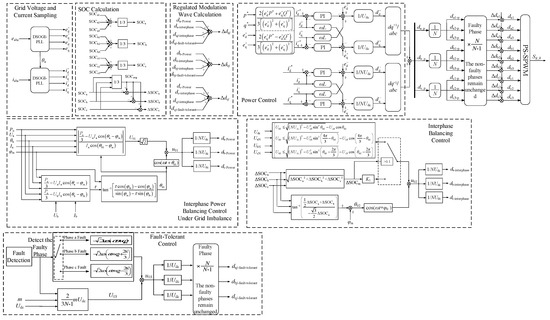
Figure A1.
Cascade-type PCS overall control block diagram.
References
- Babu, R.M.; Alam, M.S.; Islam, A.; Islam, M.K. Toward Sustainable and Clean Energy Futures: A Techno-Economic Review of Solar PV Systems, Challenges, and Opportunities. IEEE Access 2025, 13, 169720–169757. [Google Scholar] [CrossRef]
- Uwagboe, J.O.; Saha, A.K. A Comprehensive Review of Multilevel Inverter Topologies and Control Strategies for Grid-Connected Photovoltaic Battery Energy Storage Systems Integrating Active Power Filter. IEEE Access 2025, 13, 169989–170016. [Google Scholar] [CrossRef]
- Golestan, S.; Guerrero, J.M.; Vasquez, J.C. Three-Phase PLLs: A Review of Recent Advances. IEEE Trans. Power Electron. 2021, 36, 4876–4894. [Google Scholar] [CrossRef]
- Marangalu, M.G.; Rehman, F.U.; Kurkdjian, N.V. A Review of Grid-Connected Inverters and Control Methods Under Unbalanced Grid Conditions. In Proceedings of the 2025 16th Power Electronics, Drive Systems, and Technologies Conference (PEDSTC), Tabriz, Iran, 4–6 February 2025; pp. 1–7. [Google Scholar] [CrossRef]
- Liang, X.; Li, R.; Cai, X. Control of a battery-energy-storage system based on a cascaded H-Bridge converter under fault condition. In Proceedings of the 7th International Power Electronics and Motion Control Conference, Harbin, China, 2–5 June 2012; pp. 952–957. [Google Scholar] [CrossRef]
- Cao, W.; Xu, Y.; Han, Y.; Ren, B. Comparison of cascaded multilevel and modular multilevel converters with energy storage system. In Proceedings of the 2016 IEEE 11th Conference on Industrial Electronics and Applications (ICIEA), Hefei, China, 5–7 June 2016; pp. 290–294. [Google Scholar] [CrossRef]
- Zhang, X.; Sun, S.; Zhou, J.; Hong, Y.; Wang, T. Self-Adaptive Balance Control Strategy of Cascaded H-Bridge Multilevel Power Conversion System of Battery Energy Storage. In Proceedings of the 2022 IEEE 5th International Electrical and Energy Conference (CIEEC), Nangjing, China, 27–29 May 2022; pp. 2424–2429. [Google Scholar] [CrossRef]
- Yang, X.; Xue, Y.; Chen, B. Enhanced modular multilevel converter based battery energy storage system. In Proceedings of the IEEE Energy Conversion Congress and Exposition(ECCE), Cincinnati, OH, USA, 1–5 October 2017; pp. 4914–4919. [Google Scholar]
- Liang, H.; Guo, L.; Song, J. State-of-charge balancing control of a modular multilevel converter with an integrated battery energy storage. Energies 2018, 11, 873. [Google Scholar] [CrossRef]
- Liu, H.; Wu, H.; Liu, Z.; Xing, H. Research on Photovoltaic Grid Connected Stability Based on Decoupled Active Disturbance Rejection Control. In Proceedings of the 2023 5th International Conference on Power and Energy Technology (ICPET), Tianjin, China, 27–30 July 2023; pp. 1271–1277. [Google Scholar] [CrossRef]
- Li, G.; Tao, Y.; Liu, Z. Decoupled Active and Reactive Power Control for Asymmetric Cascade Multilevel Energy Storage System. In Proceedings of the 2018 5th IEEE International Conference on Cloud Computing and Intelligence Systems (CCIS), Nanjing, China, 23–25 November 2018; pp. 1043–1047. [Google Scholar] [CrossRef]
- Zhu, X.; Li, Y.; Tao, Y.; Zhang, Q.; Xue, J.; Zhou, C.; Yang, Z. Power Decoupling Control Strategy of 35 kV Cascaded H-Bridge Energy Storage System. In Proceedings of the 2020 IEEE International Conference on Networking, Sensing and Control (ICNSC), Nanjing, China, 30 October–2 November 2020; pp. 1–6. [Google Scholar] [CrossRef]
- Mathe, L.; Burlacu, P.; Schaltz, E.; Teodorescu, R. Battery pack state of charge balancing algorithm for cascaded H-bridge multilevel converters. In Proceedings of the 2016 IEEE 16th International Conference on Environment and Electrical Engineering (EEEIC), Florence, Italy, 7–10 June 2016; p. 16. [Google Scholar]
- Li, H.; Li, X.; Xiong, L.; You, L. SOC Balance Control Strategy Based on High Voltage Cascaded Power Conversion System. In Proceedings of the 2024 3rd International Conference on Energy and Electrical Power Systems (ICEEPS), Guangzhou, China, 14–16 July 2024; pp. 1341–1344. [Google Scholar] [CrossRef]
- Liu, H.; Xiao, Q.; Yu, H.; Tian, S.; Wang, W.; Tian, C.; Mu, Y.; Jia, H. An Improved Multilayer State of Charge Balancing Control Strategy for the Cascaded H-Bridge-Based Battery Energy Storage System. In Proceedings of the 2022 4th International Conference on Smart Power & Internet Energy Systems (SPIES), Beijing, China, 9–12 December 2022; pp. 1939–1944. [Google Scholar] [CrossRef]
- Shi, Y.; Duan, S. Individual Phase Current Control Based on Optimal Zero-Sequence Current Separation for a Star-Connected Cascade STATCOM Under Unbalanced Conditions. IEEE Trans. Power Electron. 2016, 31, 2099–2110. [Google Scholar] [CrossRef]
- Li, R.; Fletcher, J.E. A Novel MMC Control Scheme to Increase the DC Voltage in HVDC Transmission Systems. Electric Power Syst. Res. 2016, 143, 544–553. [Google Scholar] [CrossRef]
- Yadav, S.K.; Mishra, N.; Singh, B. Optimal third harmonic injection based nearest level control of large-scale solar photovoltaic multilevel converter. Energy Convers. Econ. 2022, 3, 61–71. [Google Scholar] [CrossRef]
- Zhou, L.; Preindl, M. Zero sequence power balancing compensation for third harmonic injection of multi-stage grid-tied energy conversion systems. In 2022 IEEE/AIAA Transportation Electrification Conference and Electric Aircraft Technologies Symposium (ITEC+EATS); IEEE: New York, NY, USA, 2022. [Google Scholar] [CrossRef]
- Eroğlu, F.; Kurtoğlu, M.; Eren, A.; Vural, A.M. Multi-objective control strategy for multilevel converter based battery D-STATCOM with power quality improvement. Appl. Energy 2023, 341, 121091. [Google Scholar] [CrossRef]
- Li, X.; Song, Q.; Liu, W.; Li, Q.; Rao, H.; Xu, S. Zero-sequence voltage injection control scheme of modular multilevel converter supplying passive networks under unbalanced load conditions. Electr. Power Syst. Res. 2015, 121, 270–278. [Google Scholar] [CrossRef]

Disclaimer/Publisher’s Note: The statements, opinions and data contained in all publications are solely those of the individual author(s) and contributor(s) and not of MDPI and/or the editor(s). MDPI and/or the editor(s) disclaim responsibility for any injury to people or property resulting from any ideas, methods, instructions or products referred to in the content. |
© 2026 by the authors. Licensee MDPI, Basel, Switzerland. This article is an open access article distributed under the terms and conditions of the Creative Commons Attribution (CC BY) license.