


Abstract
Deterministic, microsecond-level timing reproduction in full-system virtualization remains a key challenge for hardware-in-the-loop simulation of timing-sensitive communication buses. This paper presents a virtual time-driven approach that models protocol timing semantics as discrete events on a deterministic virtual timeline, and validates it using MIL-STD-1553B, a representative aerospace bus with strict microsecond-level requirements, as a case study. The MIL-STD-1553B data bus is widely used in aerospace and high-reliability embedded systems, where communication correctness depends not only on message formats but also critically on microsecond-level timing semantics such as message intervals, frame periods, response timeouts, and automatic retries. However, existing Quick Emulator (QEMU)-based virtualization solutions typically rely on host scheduling for timing, making it difficult to maintain determinism under varying loads, which may lead to missed detections or false alarms in timeout/retry behaviors. This paper implements a configurable BU-64843 device model supporting bus controller (BC), remote terminal (RT), and monitor terminal (MT) multi-role switching under a unified framework and completes behavioral modeling of both legacy and enhanced bus controllers covering message scheduling, execution, and exception handling paths. We propose a virtual time-driven precise timing modeling method that explicitly models key timing semantics as discrete events on a virtual timeline. Extensive experiments across 10 timing scenarios demonstrate that our method reduces timing deviation from an average of 8 µs to 65–124 ns (99.1% improvement), achieving deterministic simulation decoupled from host execution speed while meeting the 1 µs minimum resolution requirement. While demonstrated on 1553B, the virtual time-driven method is applicable to other timing-sensitive bus protocols in QEMU-based simulation environments, offering a low-cost, reproducible, and high-precision simulation environment for protocol compliance verification, driver development, and system integration.
1. Introduction
The MIL-STD-1553B bus, as a long-standing airborne data bus standard widely used in aerospace and high-reliability embedded systems, undertakes critical mission communications in scenarios such as flight control, avionics integration, mission payloads, and multi-agent coordination. With the increasing scale of systems and the complexity of mission modes, the research and verification requirements for 1553B-related software and hardware exhibit engineering characteristics of “high-frequency iteration, strong consistency, and reproducibility”—not only requiring verification of functional correctness in message formats and interaction protocols but also continuous verification of protocol compliance and system robustness under numerous boundary conditions and exception paths. Therefore, a simulation and verification environment capable of reproducing 1553B communication behaviors with low cost and high reproducibility has become important infrastructure supporting driver development, system integration, and automated testing.
Traditional 1553B verification typically relies on physical hardware boards or hardware-in-the-loop (HIL) platforms. While these methods naturally meet electrical characteristics and timing constraints, they simultaneously face problems of high cost, long setup cycles, and poor test scenario adaptability; particularly when covering complex scheduling sequences, boundary timing, and exception retry paths, frequent bench configuration changes are often required, making it difficult to support rapid iteration and large-scale case regression. In contrast, full-system simulation virtualization platforms (such as Quick Emulator (QEMU)) can reproduce processors, memory, and peripherals in software form on general-purpose hosts, providing low-cost, reproducible, and easily scalable environments for OS porting, driver development, system integration, and automated testing. Thus, a natural question arises: can a credible 1553B device model be built within QEMU’s mature full-system simulation ecosystem that satisfies both functional closure and supports protocol-level verification and regression?
The communication reliability of 1553B depends not only on the functional correctness of message formats and interaction protocols, but even more critically on whether microsecond-level timing semantics such as message intervals, frame scheduling, response timeouts, and automatic retries can be strictly satisfied. The standard gives clear constraints on key timing; once timing deviations exceed the window, protocol judgment results are directly altered: on one hand, simulations may have insufficient delays, causing timeouts or retries that should trigger in real systems to be misjudged as successes, leading to missed detection defects; on the other hand, if simulations introduce jitter or additional delays, they may create timeouts or retries that do not exist in real systems, leading to distorted verification conclusions.
Unlike existing 1553B simulation approaches that either rely on expensive hardware platforms or suffer from inadequate timing precision, our work targets a fundamentally different approach: achieving microsecond-level timing accuracy entirely within software-based full-system virtualization. In contrast to prior QEMU-based device models that implicitly depend on host execution speed for timing semantics, our method explicitly decouples simulation timing from host performance through virtual time-driven modeling. This key distinction enables deterministic reproduction of protocol-level timing behaviors regardless of host system load or execution speed variations. We choose QEMU as the virtualization platform because its icount mode provides a deterministic virtual timebase tied to instruction execution rather than host wall-clock time, enabling fully reproducible timing behavior. Combined with full-system emulation capability and a broad device model ecosystem, QEMU provides a suitable foundation for timing-sensitive bus simulation that pure protocol simulators or cycle-accurate models cannot easily match (see Section 6.1 for further discussion).
This paper addressed the challenge of achieving deterministic timing reproduction in QEMU-based full-system simulation, proposing a virtual time-driven precise timing modeling method and validating it through a complete MIL-STD-1553B implementation as a representative case study. The main contributions of this paper are summarized as follows:
- Unified Device Model: We design and implement a configurable BU-64843 device model supporting BC/RT/MT multi-role switching under a unified framework, eliminating redundant implementation and improving reusability for system-level verification.
- Virtual Time-Driven Timing Mechanism: We propose a general virtual time-driven precise timing modeling method that explicitly models key timing semantics (message intervals, frame timing, response timeouts, retries) as discrete events on a virtual timeline, achieving deterministic simulation decoupled from host execution speed. While instantiated here for 1553B, the method applies to any protocol with microsecond-level timing constraints.
- Complete Behavioral Modeling: We implement comprehensive behavioral modeling for both legacy BC (descriptor-block-driven scheduling) and enhanced BC (lightweight instruction execution engine), covering message sending/receiving, frame auto-repeat, timeouts, and retry handling paths.
- Quantified Performance Improvement: We demonstrate through extensive experiments across 10 timing scenarios that our method reduces timing deviation from an average of 8 µs to 65–124 ns (99.1% improvement), achieving deterministic simulation while meeting the 1 µs minimum resolution requirement. These results confirm the feasibility of the virtual time-driven approach for timing-sensitive bus simulation in general.
The rest of this paper is organized as follows: Section 2 reviews related work; Section 3 introduces the overall system architecture and unified device model; Section 4 elaborates on the virtual time-driven precise timing modeling method; Section 5 presents experimental evaluation and compares precise timing with traditional methods; Section 6 discusses the appropriateness of QEMU for timing-sensitive simulation, the generalizability of the approach to other protocols, and its limitations; Section 7 concludes the paper and outlines future work.
2. Related Work
2.1. 1553B Simulation and Verification Approaches
Traditional 1553B verification primarily relies on physical hardware boards or hardware-in-the-loop (HIL) platforms. While these methods naturally meet electrical characteristics and timing constraints, they face significant challenges in terms of high cost, long setup cycles, and poor test scenario adaptability. In particular, when covering complex scheduling sequences, boundary timing conditions, and exception retry paths, frequent bench configuration changes are often required, making it difficult to support rapid iteration and large-scale case regression.
To address these limitations, software-based simulation approaches have been explored. Deniz et al. [1] proposed a DDS-based distributed 1553B simulation tool to eliminate expensive hardware and dedicated cabling. Their approach enables cost-effective simulation but suffers from end-to-end latency at the hundred-microsecond level on general PCs, making it difficult to meet 1553B’s strict timing requirements. The coarse timing granularity provides unreliable semantics for scenarios involving timeout and retry boundary verification, where microsecond-level precision is critical.
The representative work in full-system simulation platforms comes from Engblom et al. [2], who built a multi-node LEON2 system on Virtutech Simics and implemented 1553 interconnection. However, their model adopts simplified assumptions of fixed delays over time, which cannot be used to analyze or predict precise periodic timing behavior. Furthermore, the interconnection uses transaction-level abstraction rather than explicit bus cycle-driven approaches, making it difficult to support microsecond-level protocol judgment and verification.
Additionally, 1553B models on other simulation platforms often cannot directly utilize QEMU’s massive device ecosystem to quickly build closed-loop verification boards, resulting in long joint simulation setup cycles and high integration costs. This limits their practical utility for rapid prototyping and agile development workflows.
2.2. Quick Emulator (QEMU)-Based Device Emulation
QEMU has emerged as a mature full-system simulation platform capable of reproducing processors, memory, and peripherals in software form on general-purpose hosts. It provides low-cost, reproducible, and easily scalable environments for OS porting, driver development, system integration, and automated testing. QEMU has been successfully applied across diverse application domains: Zabolotny [3] demonstrated QEMU-based hardware/software co-development for data acquisition (DAQ) systems, enabling early software development and testing in a simulated hardware environment. In the automotive domain, Jünger et al. [4] presented a framework for constructing virtual Electronic Control Units (ECUs) using QEMU and SystemC TLM-2.0, combining the speed of QEMU with the modeling capabilities of SystemC for automotive software testing. For IoT applications, Späthe et al. [5] proposed a simulation environment using Zephyr RTOS and QEMU for benchmarking IoT device usage scenarios across diverse application contexts. For cloud infrastructure emulation, Decker et al. [6] developed Q8S, a tool for emulating heterogeneous Kubernetes clusters using QEMU on OpenStack, enabling automatic setup of highly available Kubernetes clusters based on user specifications. For educational purposes, Poduval [7] implemented a virtual memory-to-memory scaler hardware device using QEMU as a platform for Linux device driver development, demonstrating how virtual hardware can serve as a learning tool without requiring physical hardware. To streamline device model creation, Efimov et al. [8] proposed automation techniques for QEMU device and machine development, analyzing QEMU internals to identify workflow stages that can be automated. In the security domain, Spensky et al. [9] developed Conware, a framework for automated modeling of hardware peripherals using machine learning techniques, reducing dependency on physical hardware for security analysis and testing. Building on automated device modeling, Ma et al. [10] proposed Truman, a system that constructs device behavior models from OS drivers to fuzz virtual devices, automatically inferring dependencies from open-source drivers to improve virtual device testing.
Recent work has explored combining QEMU with finer time models. For example, QEMU-CAS [11] uses QEMU as the full-system functional front-end and introduces cycle-accurate CPU performance models, while allowing decoupling of function and latency at memory interfaces. This approach successfully achieves high accuracy for processor microarchitecture evaluation and performance analysis. Outside QEMU, other full-system simulators have also demonstrated high-fidelity device modeling capabilities: Wang et al. [12] developed CXL-DMSim, a gem5-based simulator that achieves comprehensive silicon validation for CXL disaggregated memory systems through flexible device models and protocol support. Other efforts have focused on enabling hardware modeling through QEMU’s integration with hardware description languages: Yeh and Chiang [13] proposed an interface between QEMU and SystemC for co-simulation, allowing hardware models described in SystemC to be connected to QEMU-based virtual platforms. Similarly, Biagetti et al. [14] developed an open-source hardware/software co-simulation framework using QEMU and GHDL for VHDL-based SoC design, enabling co-simulation of VHDL hardware designs with the firmware that controls them. To improve simulation performance, Díaz et al. [15] enabled external synchronization of QEMU in its parallelized mode for hardware/software co-simulation, demonstrating strategies for integrating discrete event simulators with QEMU.
However, such work primarily targets processor microarchitecture and performance evaluation, where the modeling goal is to faithfully replicate CPU pipeline behavior and cache coherence protocols. In contrast, 1553B protocol simulation requires “protocol timing semantic consistency”—ensuring that message intervals, frame timing, response timeouts, and retry behaviors strictly adhere to microsecond-level constraints regardless of host execution speed. This fundamental difference in modeling objectives means that existing QEMU-based timing solutions cannot be directly applied to 1553B protocol verification without significant adaptation.
More critically, by default, QEMU’s timing event triggering precision often remains at the level of tens of microseconds. Experiments show that under idle conditions, setting a periodic timing event of 50 µs yields an average interval of approximately 82.8 µs; setting 100 µs yields an average interval of approximately 140.3 µs, showing significant additional latency. This mechanism, where time advancement is implicitly determined by host scheduling and execution paths, easily introduces uncontrollable jitter under load variations. This non-determinism makes it impossible to stably reproduce 1553B message intervals, frame scheduling, response timeout, and retry trigger conditions at the microsecond scale.
2.3. Timing Modeling in Virtualization Platforms
The challenge of achieving precise timing in virtualized environments has been extensively studied. Traditional approaches include time division multiplexing (TDM), where time slices are allocated to different virtual machines, and paravirtualization, where guest OSes are modified to be aware of virtualization timing constraints.
However, these approaches still fundamentally rely on host scheduling for time advancement. When the hypervisor or host system is under load, timing events may be delayed or advanced unpredictably, introducing jitter that can exceed protocol-specified timing windows. For real-time protocols like 1553B, where a single missed timeout or incorrectly triggered retry can alter protocol semantics, such non-determinism is unacceptable.
2.4. Positioning of Our Work
In summary, existing research has not directly addressed the challenge of implementing microsecond-level timing semantics within the QEMU peripheral simulation framework while ensuring deterministic reproduction decoupled from host execution speed. Our work differs from prior approaches in several key aspects:
Unlike DDS-based approaches [1] that suffer from end-to-end latency at the hundred-microsecond level on general PCs (approximately 100 µs end-to-end latency) (making it impossible to verify 1553B’s strict microsecond-level timing constraints), our method achieves sub-250 ns timing accuracy through virtual time-driven modeling—a more than 400× improvement in timing precision. In contrast to Simics-based models [2] that rely on fixed-delay assumptions and cannot analyze or predict precise periodic timing behavior and does not quantify timing deviation, we explicitly model timing constraints as discrete events on a virtual timeline, enabling accurate prediction of message intervals, frame timing, and retry triggers. While QEMU-CAS [11] successfully decouples function and latency for CPU performance evaluation through cycle-accurate modeling, its primary focus on processor microarchitecture differs fundamentally from our focus on protocol timing semantic consistency for bus communication. Furthermore, unlike traditional QEMU peripheral modeling where timing events exhibit jitter exceeding 40–80 µs under load due to host scheduling dependencies, our virtual time mechanism maintains consistent timing with deviation under 250 ns regardless of host system load, a reduction of more than 160× in timing deviation.
To the best of our knowledge, this is the first work to achieve deterministic 1553B protocol simulation in QEMU with microsecond-level timing accuracy, enabling reliable verification of timeout, retry, and frame timing behaviors independent of host system load and execution speed.
3. System Overall Architecture
MIL-STD-1553B is a typical multi-role centralized bus protocol where communication is uniformly scheduled by the bus controller (BC), remote terminals (RT) send and receive data according to commands, and monitor terminals (MT) are used for listening and recording; systems typically use A/B dual redundant physical buses to enhance fault tolerance. In real hardware, roles such as BC/RT/MT are typically switched through register configuration on the same type of 1553 interface chip (rather than different physical devices). Therefore, in system-level virtualization simulation, the key lies in implementing consistent resource abstraction for multi-role behaviors under a unified device model and providing verifiable execution and timing mechanisms at the protocol timing semantic level.
3.1. Model System Overall Architecture
This paper builds a QEMU-based 1553B full-system simulation platform on a Linux host. The system uses QEMU Virtual Machines (VMs) as basic execution units: each VM runs containing processors, drivers, and programs, with custom 1553B interface device models attached via the system bus. Upper-layer software completes protocol configuration, message triggering, and status acquisition by reading and writing registers and on-chip RAM.
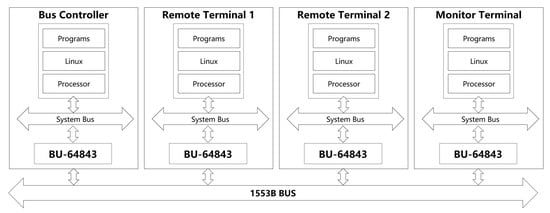
As shown in Figure 1, the system consists of multiple nodes connected to a shared 1553B bus, including a bus controller (BC), multiple remote terminals (RT1, RT2), and a monitor terminal (MT). The BC initiates all communication by sending commands to RTs, while the MT passively listens to all bus traffic for monitoring and diagnostic purposes.
Figure 1.
1553B bus system topology showing bus controller (BC), remote terminals (RT1, RT2), and monitor terminal (MT) connected via system bus and 1553B BUS.
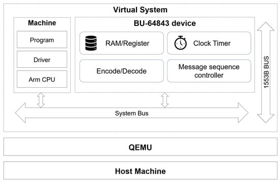
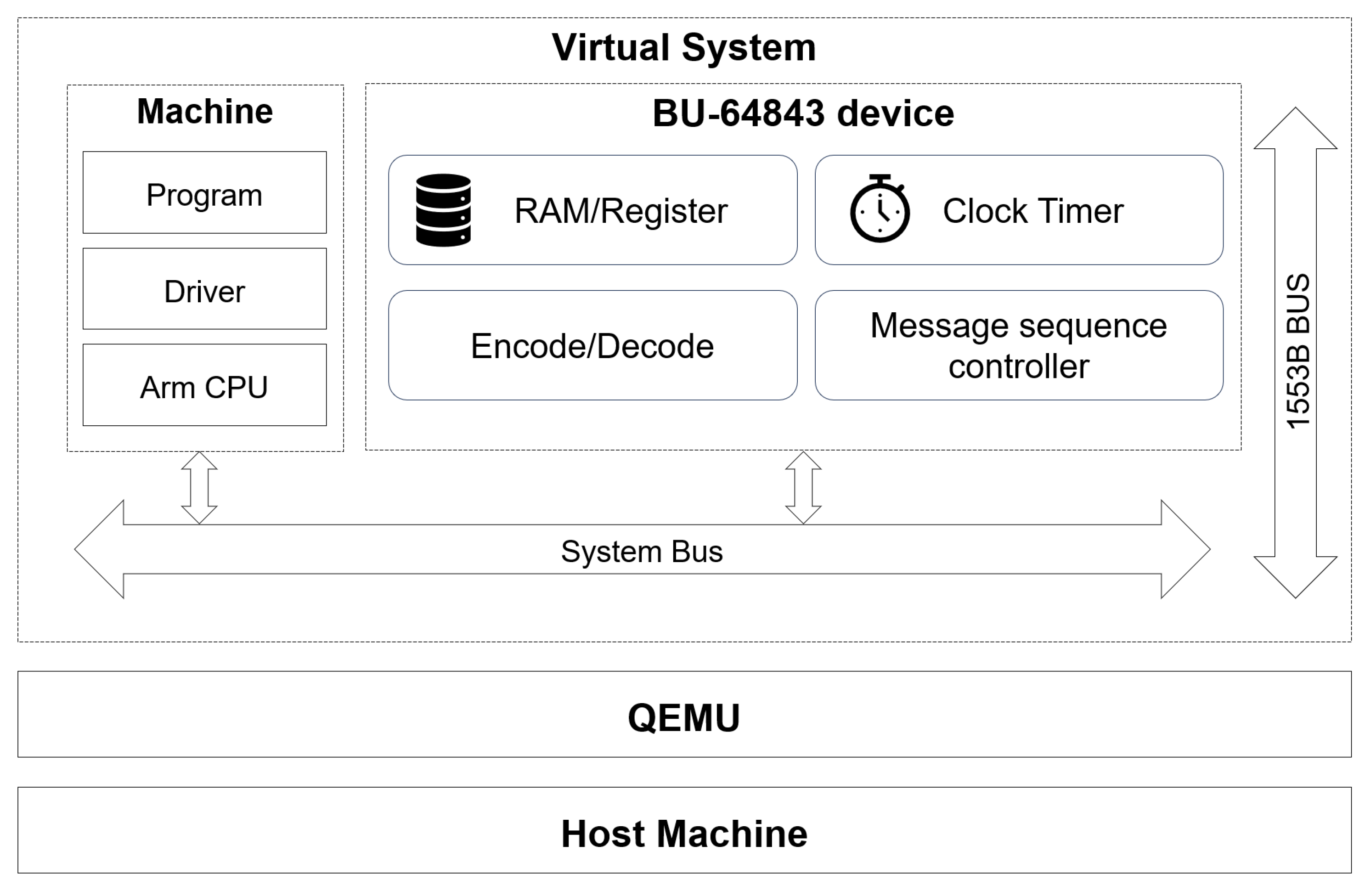
As shown in Figure 2, the physical host runs QEMU 9.0.0 (Quick Emulator, QEMU Project, open-source software), which creates virtual systems containing simplified machines with ARM CPUs, programs, and drivers. The BU-64843 device model is attached to the system bus, providing a complete 1553B interface including message processors, timers, and interrupt managers.
Figure 2.
QEMU-based 1553B bus system virtualization architecture showing host machine, QEMU emulator, and virtual system with machine (ARM central processing unit (CPU), program, driver) and BU-64843 device.
3.2. Unified Interface Device Model
This work simulates the 1553B bus based on the BU-64843 interface device, a commercial off-the-shelf (COTS) 1553B terminal from Data Device Corporation (DDC, Bohemia, NY, USA) widely used in aerospace and defense applications. The device integrates 4K words of internal RAM and 64 × 16-bit registers, supporting configuration of traditional BC, enhanced BC, RT, MT, and other device forms through registers. In the device model, register space is used to describe protocol status, message control information, role selection, and interrupt/exception status; RAM is used to store protocol runtime data structures such as message control blocks, data areas, and status write-back areas. Through configuration of key control registers, the device can operate in BC, RT, or MT modes, with underlying storage structures and register semantics remaining consistent, thereby limiting bus role differences to the behavioral logic level rather than involving physical resource division, enhancing model reusability and extensibility.
3.3. Legacy Bus Controller Modeling
Based on the unified device model, both legacy BC and enhanced BC are modeled. Legacy BC lacks independent instruction parsing and complex scheduling capabilities, with its execution driven by data structures pre-organized in RAM. The model adopts a “stack area/message descriptor block” abstraction: descriptor blocks record message type, control words, data area locations, and status write-back locations; the BC maintains stack pointers and message counters to determine sequential fetching of messages within a frame, supporting modes such as frame auto-repeat.
During execution, the system first selects the memory stack area A/B to process messages based on configuration registers. At startup, the system first transfers the initial stack pointer and initial message count to the stack pointer and message count locations. When starting to send messages, it first finds the corresponding message’s descriptor block from the descriptor stack based on the stack pointer and records the time tag word in the descriptor block. Based on the message block pointer in the descriptor block, it finds the corresponding message block. It first sends the control word, then receives data words from the RT, and finally receives the RT’s status word. After message reception is complete, the initial stack pointer is incremented by four, and the message count is decremented by one, then the next message is executed. When the message count reaches 0, if frame auto-repeat mode is disabled, execution stops. Otherwise, after the message ends, the initial stack pointer and initial message count are again transferred to the stack pointer and message count locations, and the next frame begins, cyclically sending messages.
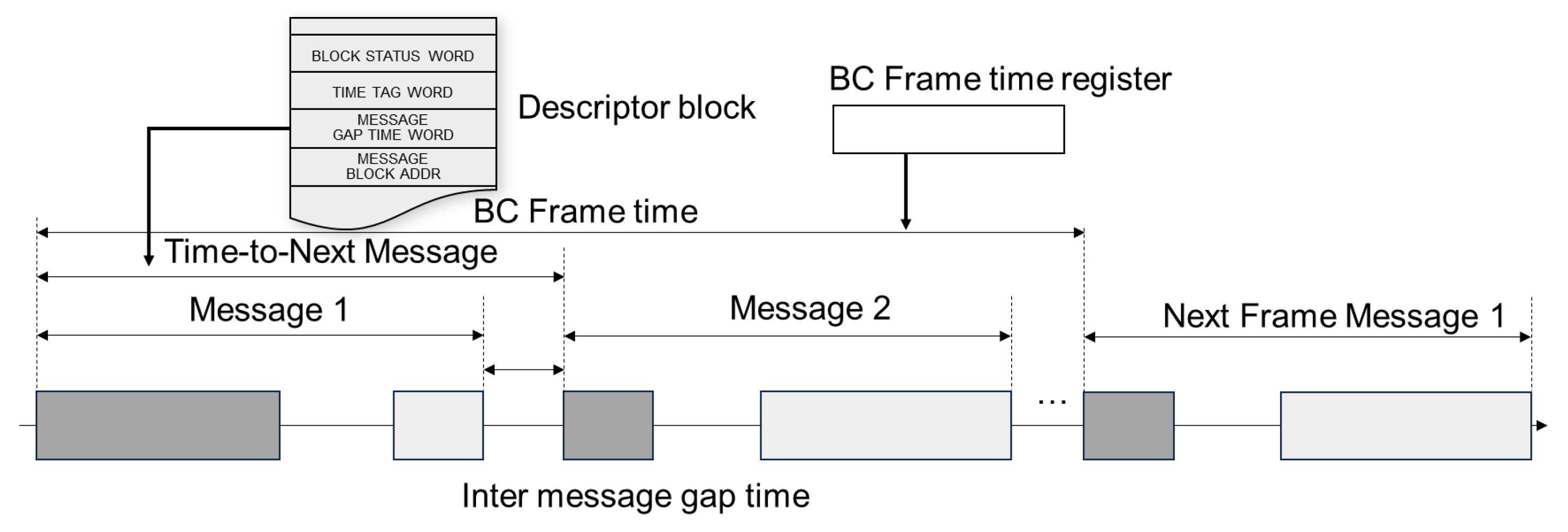
The time-to-next-message is the time interval from the start of one message to the start of the next, controlled by the message interval time word in the message descriptor stack, with a resolution of 1 µs/LSB and a range of 0–65,535 µs, and the message interval time must not be less than 10 µs. When a message ends, if the time-to-next-message is less than 10 µs, a 10 µs interval must occur before executing the next message. BC frame time is the interval from the start of one frame to the start of the next frame, determined by the BC frame time register with a time resolution of 100 µs/LSB and a range of 0–6.5535 s. Additionally, there are configurable timeouts of 18.5/22.5/50.5/130 µs from the BC sending a word to receiving the first word. When configured for retry, if the RT response times out, the BC resends the message.
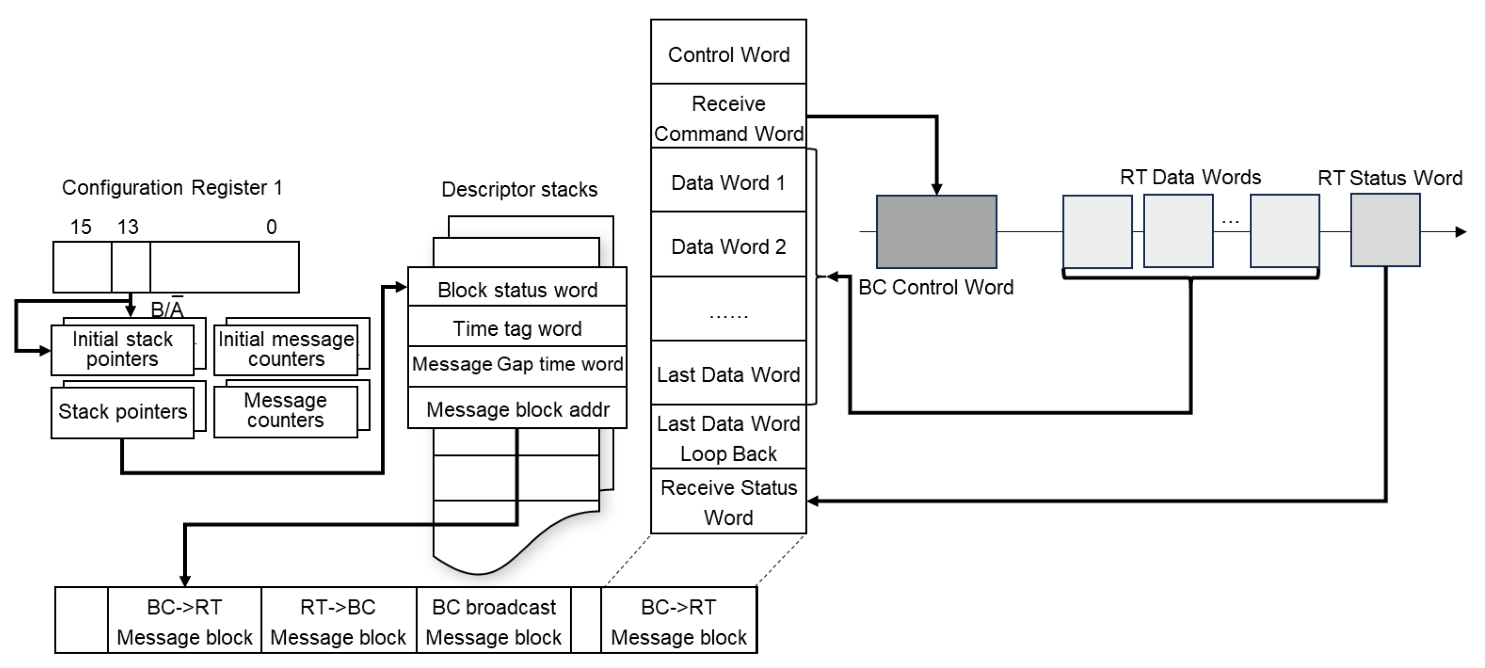
As illustrated in Figure 3, the configuration register, stack pointers, message counters, and descriptor stacks work together to manage the sequential execution of messages within a frame. Each descriptor block contains block status words, time tag words, message gap time words, and message block addresses, supporting features such as frame auto-repeat.
Figure 3.
Legacy BC descriptor stack and message processing architecture showing configuration register, stack pointers, descriptor stacks, data word stack, and message blocks (from BC to RT, from RT to BC, and broadcast).
BC behavior is jointly determined by message type, word-level state machine, register configuration, and exception conditions such as timeout/retry. To reduce implementation complexity and enhance consistency, this paper decomposes message flows into determinable word-level processing methods and encapsulates them through unified send, receive, and completion paths to cover legacy BC’s complete operational behavior. To ensure a minimum 1 µs time resolution and guarantee frame interval and message interval timing, this paper maps all times to a virtual timeline, achieving precise timing and thereby ensuring the model’s timing correctness.
3.4. Enhanced Bus Controller Modeling
Enhanced BC can execute autonomously through instructions. Enhanced BC further decouples message scheduling and execution from fixed descriptor block structures, including an instruction set with 21 instructions, introducing programmable message sequence control capabilities that can achieve conditional judgment, execution flow transfer, automatic retry, and other capabilities. Among these, some instructions have the ability to change flag registers and conditional execution, and some instructions require parameters to execute. It includes a general-purpose queue for communicating with the processor and a call stack for function calls. Using message timers, frame timers, and watchdogs implements frame and message timing and avoids faults.
The instruction set includes multiple time-related instructions, as shown in Table 1. To achieve precise timing, this paper maps events to a virtual timeline based on a timing module, reducing timing errors and meeting the minimum 1 µs time resolution requirement. Meanwhile, in enhanced BC, a watchdog timer exists, configured by the BC frame time register with a resolution of 100 µs/LSB.
Table 1.
Time-related instructions in enhanced BC.
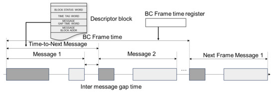
As shown in Figure 4, the BC frame timing structure defines how messages are organized and scheduled within a frame. The descriptor block contains control information including block status word, time tag word, message gap time word, and message block address. The BC frame time register controls the overall frame timing, determining when each message starts and ensuring proper inter-message gaps. This structure is central to how the 1553B protocol maintains deterministic message delivery and frame-level timing control.
Figure 4.
BC frame timing structure showing descriptor block (block status word, time tag word, message gap time word, message block address), BC frame time register, and message timeline with inter-message gaps. Time-to-Next Message is determined by the MESSAGE GAP TIME WORD in the descriptor block, while BC Frame Time is determined by the BC Frame Time Register.
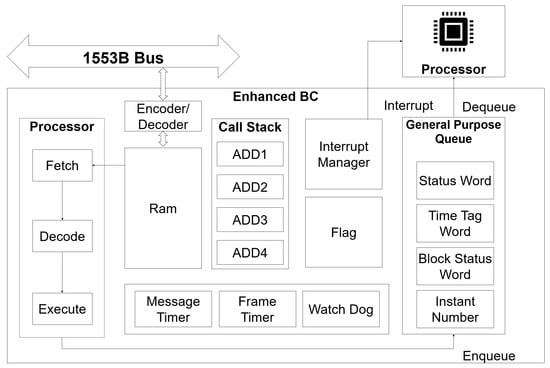
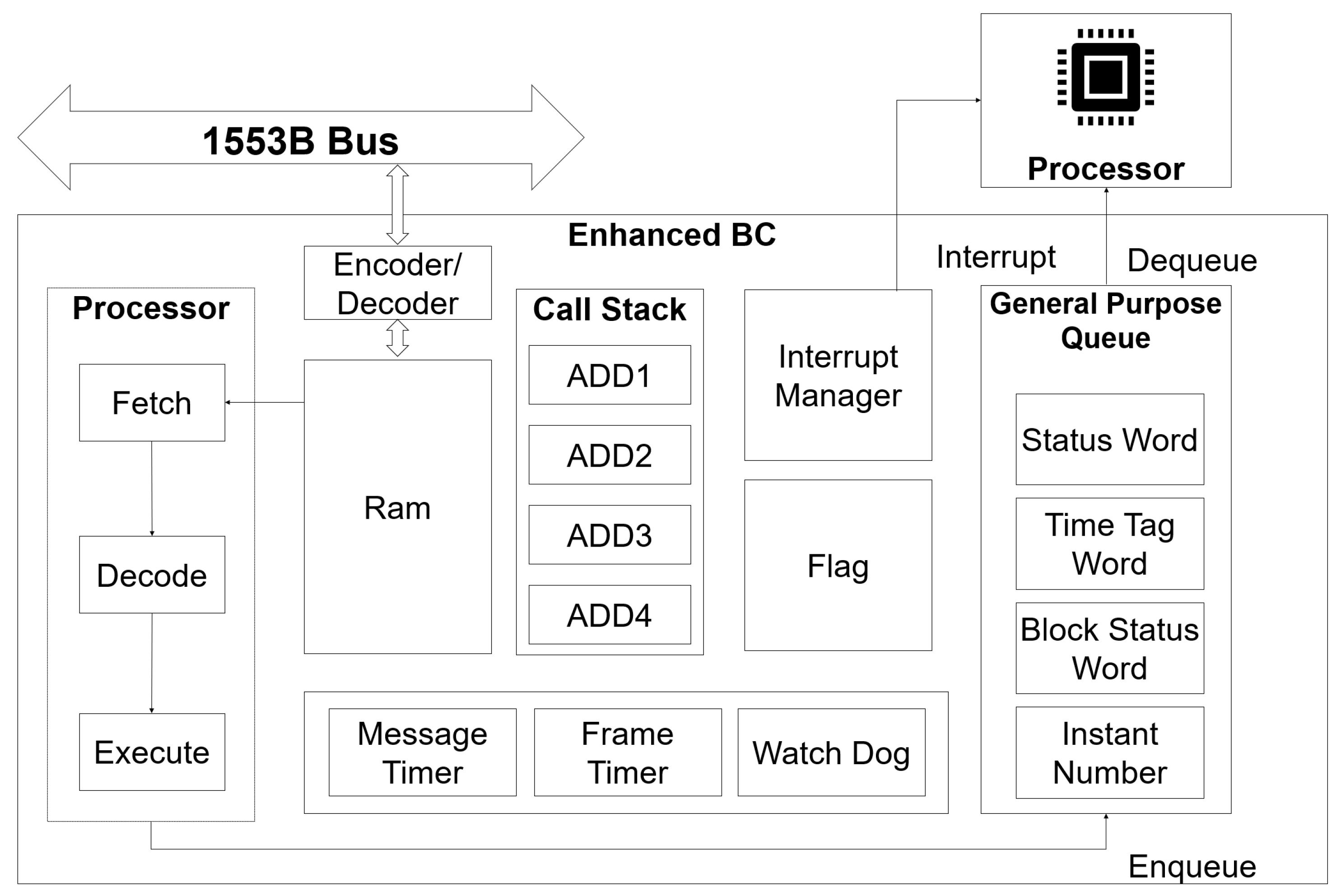
Figure 5 illustrates the internal architecture of the enhanced BC. The diagram shows the processor with fetch-decode-execute cycle, encoder/decoder for bus communication, RAM/register storage, call stack for function calls, interrupt manager, flag registers, general-purpose queue for status reporting, and three timers (message timer, frame timer, and watchdog). This architecture enables the enhanced BC to autonomously execute complex message scheduling sequences without continuous main CPU intervention.
Figure 5.
Enhanced BC internal architecture showing instruction processor with fetch-decode-execute cycle, encoder/decoder for bus communication, RAM/register storage, call stack, interrupt manager, flag registers, general-purpose queue, and three timers (message timer, frame timer, watchdog).
In the QEMU device model, this paper abstracts it as a lightweight instruction processor that internally maintains an instruction pointer register, sequentially fetches instructions from RAM, and generates actions (send messages/conditional branch/retry control/interrupt trigger/jump, etc.) through fetch, decode, and execute, thereby modeling enhanced BC’s autonomous scheduling characteristics. This modeling approach can offload complex communication tasks from the main CPU to the BC execution engine, maintaining consistency with real chip behavior at the architectural level. To ensure time-related instructions execute precisely, this paper maps events to a virtual timeline through a timing module, thereby ensuring enhanced BC timing.
By simultaneously accommodating both legacy and enhanced BC execution semantics within the same device model, changing register configurations allows the platform to cover different chip operating modes without changing upper-layer software interfaces, providing unified support for subsequent timing verification, driver development, and system integration.
3.5. Timing Subsystem
Since message intervals, frame periods, response timeouts, and retry triggers in 1553B are part of the protocol semantics, the platform sets up a virtual time-driven timing subsystem within the device model: using the simulation virtual clock as a baseline, key timing conditions such as message interval end, frame period expiration, timeout triggers, and retry windows are modeled as discrete events, driven by an event scheduler to cause BC execution engine state transitions. This design makes protocol timing no longer implicitly depend on host scheduling and execution speed, ensuring subsequent precision from the system architecture level, allowing events to land on a unified, controllable virtual timeline.
3.6. Software Stack Architecture
At the software level, this paper implements a supporting Linux device driver for the 1553B interface device, providing unified access interfaces to upper layers. Test programs complete role configuration, message/frame scheduling startup, status reading, and result collection through driver read/write of registers and on-chip RAM. Since the device model maintains consistent interface abstraction across different roles, upper-layer test cases and driver logic need not perceive the physical differences between BC/RT/MT, thereby enhancing multi-scenario scalability and reusability.
4. Virtual Time-Based Precise Timing Implementation Method
4.1. Timing Modeling Problem Analysis
Traditional approaches to timing modeling in full-system simulators typically rely on the host’s operating system scheduler and CPU execution speed to advance simulation time. While this “best-effort” approach may suffice for coarse-grained timing requirements, it fundamentally fails to meet the microsecond-level precision demanded by real-time protocols like 1553B. Experiments demonstrate that under idle conditions, even simple periodic timing events in QEMU exhibit average deviations of 30–40 µs from their intended intervals, with jitter increasing dramatically under host system load. In contrast, our virtual time-driven approach explicitly decouples simulation timing from host execution, achieving timing deviations under 250 ns regardless of host load—a more than 100× improvement in timing consistency.
In the MIL-STD-1553B protocol, time is not only used for performance measurement but also directly participates in protocol semantic judgment and execution control. The protocol gives clear constraints on message start, message intervals, and retry timing; for example, minimum message interval time, frame interval time, etc. These timing constraints collectively determine the response mode of remote terminals to bus behavior and are key conditions for ensuring system correctness and reliability. If time jitter is too large, communication processes may not be stably reproduced, affecting model accuracy. For example, frame time is controlled by the BC frame time register with a time resolution of 100 µs/LSB, and time-to-next-message is controlled by the message interval time word in the message descriptor block with a time resolution of 1 µs/LSB.
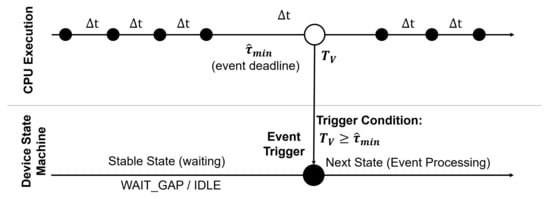
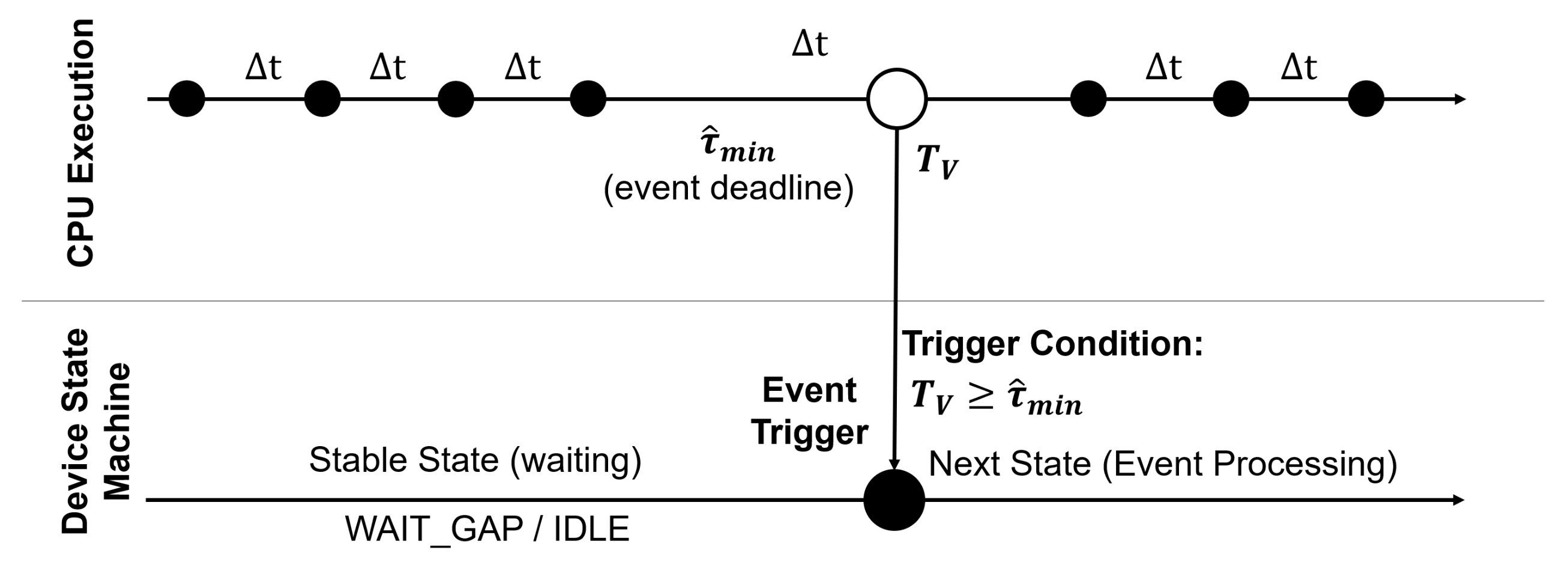
Figure 6 illustrates the event trigger timing mechanism in our virtual time-driven approach. The diagram shows CPU execution cycles with interval , a virtual time axis for tracking simulation time, and the event trigger condition () that determines when the device state machine transitions from WAIT_GAP/IDLE to the next state. This timing mechanism ensures that events fire at precise virtual time points regardless of host execution speed, which is necessary for deterministic behavior in real-time protocol simulation.
Figure 6.
Device event trigger timing diagram showing CPU execution cycles ( interval), virtual time axis, event trigger condition (), and device state machine transition from WAIT_GAP/IDLE to next state. In CPU Execution, black circles denote time points where no event is triggered, and white circles denote time points where an event is triggered. In the Device State Machine, black circles denote that an event has been triggered.
Timing-related scenarios in the device include: message interval time, frame time, response timeout, retry delay, DLY/WFT instruction delay, etc. Table 2 summarizes the main timing events and their resolution requirements.
Table 2.
Key timing events in 1553B protocol.
However, in virtualized simulation environments, timing semantics are often difficult to naturally reproduce. Traditional simulation methods typically implicitly include protocol timing in code execution flow, relying on host execution speed, thread scheduling, and system load to indirectly reflect time advancement, with latency reaching several milliseconds. This approach can only trigger basic protocol flows during functional verification, but its timing precision and stability highly depend on the runtime environment, making it difficult to guarantee consistency of microsecond-level timing constraints across multiple simulation runs. When simulation scale expands or host load changes, implicit time models often exhibit significant jitter, failing to meet 1553B protocol requirements for deterministic timing.
The virtual time axis adopts a grid-based approach with spacing ns, which bounds the maximum quantization error to at most (with expected mean error near under approximately uniform phase distribution). This design choice ensures that multiple events can be scheduled precisely on the virtual timeline, with the main loop advancing virtual time and triggering events at their scheduled times, thereby achieving deterministic timing behavior independent of host execution speed.
The error mainly originates from traditional QEMU peripheral modeling often hiding latency in execution paths, with timing functionality being a “best-effort” mechanism that typically only triggers corresponding timers after completing one round of the main loop. This causes timer trigger moments to be influenced by main loop check frequency, host thread scheduling, and load, introducing significant additional latency and long-tail jitter at the microsecond scale, making it impossible to stably reproduce window judgment semantics such as timeouts and waits.
Therefore, in this paper’s high-credibility modeling of the 1553B bus controller, key timing constraints in the protocol are precisely characterized through methods independent of host execution behavior, thereby ensuring accurate bus protocol modeling.
4.2. Precise Timing Modeling Method
To address the above problems, this paper proposes and implements a virtual time-driven timing modeling method that explicitly maps key timing behaviors related to message execution in the MIL-STD-1553B protocol to discrete events on a virtual timeline through instruction counting. On the timeline, corresponding times are triggered at fixed points. This method does not depend on host physical time advancement but is instead unifiedly driven by a virtual clock maintained internally by the simulation system, thereby maintaining consistent timing semantics across different runtime environments.
In the model, after each bus message transmission completes, the BC switches to message interval state. This state is constrained by a virtual timer; before virtual time reaches the protocol-specified minimum message interval, the model pauses message scheduling. Only when virtual time advances to a legal window does it enter the next stage. Through this mechanism, message interval constraints no longer rely on natural formation of execution delays but are instead guaranteed by model logic.
We now formalize the virtual time model and its error properties. Let the virtual time be , advanced deterministically by QEMU’s icount mechanism at a rate of one instruction per ns. We define a quantization grid with spacing ns. A timing event is a tuple where is the callback and the fire time is the deadline quantized onto the grid:
where is the protocol-specified absolute deadline (message interval end, frame period expiration, response timeout, etc.). All pending events are maintained in a priority queue ordered by ascending .
Proposition 1
(Single-event error bound). For any event , the quantization error satisfies .
Proof.
By the ceiling function in Equation (1), (the event never fires early). Since for all real x, we have . □
Proposition 2
(Non-accumulation of errors). The quantization error of the n-th event is independent of all preceding events, i.e., for all n, regardless of the number of previously fired events.
Proof.
Each deadline is computed from the absolute protocol timebase (e.g., frame start time plus the configured message interval), not relative to the previous event’s actual fire time . Therefore, the quantization of event n is independent of the error of event , and the bound from Proposition 1 applies individually to every event. □
Corollary 1.
Since ns µs, the method satisfies the MIL-STD-1553B minimum timing resolution requirement of 1 µs for all events, with expected mean quantization error of ns under approximately uniform phase distribution.
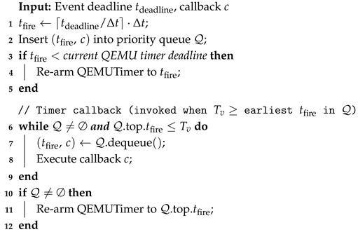
Algorithm 1 describes the event scheduling procedure. The scheduler quantizes each new deadline onto the grid, inserts it into the priority queue, and arms a single QEMU timer to the earliest deadline. When the timer fires, all due events are dispatched and the timer is re-armed.
In contrast, under the traditional “best-effort” mechanism, latency is related to main loop execution time and cannot be controlled. If the main loop is relatively busy, latency can surge dramatically, failing to meet requirements.
Our virtual time-driven mechanism is built on QEMU’s TCG instruction counting (icount) mode. When icount is enabled, QEMU derives the virtual clock (QEMU_CLOCK_VIRTUAL) from the number of executed guest instructions, rather than from host wall-clock time. In the fixed-shift mode, the virtual CPU executes one instruction every ns of virtual time, providing a deterministic timebase for timer expiration. In our experiments, we run QEMU with TCG in single-thread mode and enable icount (e.g., -accel tcg,thread=single and -icount shift=N,align=off). We also use -rtc clock=vm to keep the guest RTC driven by the virtual clock for determinism.
On top of QEMU_CLOCK_VIRTUAL, we implement a lightweight device-local discrete-event scheduler for MIL-STD-1553B timing semantics (message gaps, frame periods, response timeouts, and retry windows). This scheduler does not replace QEMU’s default timer subsystem. Instead, the BU-64843 device model maintains a priority queue of events in the QEMU_CLOCK_VIRTUAL time domain. All deadlines are quantized onto our grid with spacing ns, i.e., . The earliest deadline is propagated to a single QEMU timer (QEMUTimer) attached to QEMU_CLOCK_VIRTUAL; when it fires, all due events are dequeued and executed, and the timer is re-armed to the next earliest deadline.
| Algorithm 1: Virtual time event scheduler. |
 |
Because icount constrains execution by the next timer deadline, timer callbacks are delivered deterministically when the virtual clock reaches the programmed expiration time. The remaining timing deviation is therefore bounded by the grid quantization error (at most ), not by host scheduling jitter.
This timing mechanism combined with enhanced BC’s message scheduling model ensures that BC always uses virtual time as a unified reference baseline when executing frame auto-repeat, message scheduling, and retry control. Regardless of host execution speed, message start times, interval times, and frame periods all strictly advance according to time parameters defined in the model, thereby ensuring determinism and reproducibility of simulation behavior in the time dimension. Through this approach, timing constraints originally implicit in hardware circuits and timing logic in the 1553B protocol are transformed into controllable, verifiable event sequences in the virtual platform.
5. Experimental Evaluation
5.1. Experimental Environment and Methods
The experimental environment is built based on QEMU 9.0.0 (Quick Emulator, QEMU Project, open-source software). BC, RT1, RT2, and MT are attached to the 1553B bus for testing.
QEMU runs in TCG mode with icount enabled for determinism.
Experiments are conducted on Ubuntu 20.04 based on a 12th Gen Intel Core i9-12900HX.
In this study, the term “load” refers to the 1553B communication workload within the simulation: BC, RT1, RT2, and MT are all active on the bus, with frame auto-repeat enabled and full command/response message exchanges occurring continuously. No external host stress tools (e.g., stress-ng for CPU or memory saturation) were used. QEMU’s icount mode fully decouples virtual time advancement from the host wall-clock: regardless of host CPU or memory load, the virtual timeline advances deterministically based on instruction count, so timing behavior in the virtual time domain is independent of host conditions. This decoupling makes deterministic verification inherently independent of host load variations.
For 10 scenarios including legacy BC time-to-next message, timing precision is measured, with each scenario tested 1000 times, recording latency relative to theoretical time. Traditional QEMU and the proposed precise timing modeling are compared for minimum latency, maximum latency, average latency, standard deviation, and latency range.
5.2. Experimental Results and Analysis
To verify the effectiveness of the proposed precise timing modeling method, this paper comparatively analyzes differences in message-level time behavior before and after introducing this mechanism in the simulation system. During experiments, under identical message scheduling configurations and 1553B communication workload (BC commanding RT1 and RT2 with MT monitoring, frame auto-repeat enabled), bus communication scenarios are repeatedly executed multiple times, recording time intervals between adjacent messages and frames, and analyzing their average jitter.
Experimental results show that without the virtual time-driven mechanism, the traditional method has larger latency, with message intervals significantly influenced by host load and execution path variations, averaging between 5 µs and 9 µs, with significant jitter reaching up to 150 µs, not meeting the 1 µs-level time resolution requirement. After adopting the proposed precise timing modeling method, optimized timing jitter averages between 0.06–0.12 µs, with maximum latency of 0.25 µs, meeting protocol-specified minimum timing requirements and not exhibiting significant jitter due to changes in host runtime environment.
By default, QEMU timing uses a “best-effort” approach, checking timers only after the main loop ends, introducing average latency of 5 µs to 9 µs. Moreover, due to scheduling influence, latency can further surge.
After optimization, mapping events to timeline grid points with a grid spacing of 256 ns results in maximum latency of 255 ns in the worst case, less than 1553B’s required minimum time resolution of 1 µs. If timing events are uniformly distributed within the timeline, theoretical average latency is 127.5 ns, enabling the model to perform microsecond-level timing simulation for 1553B models.
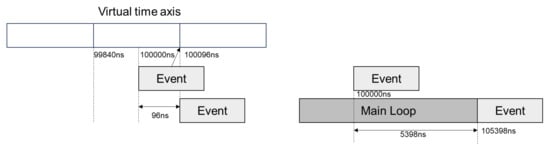
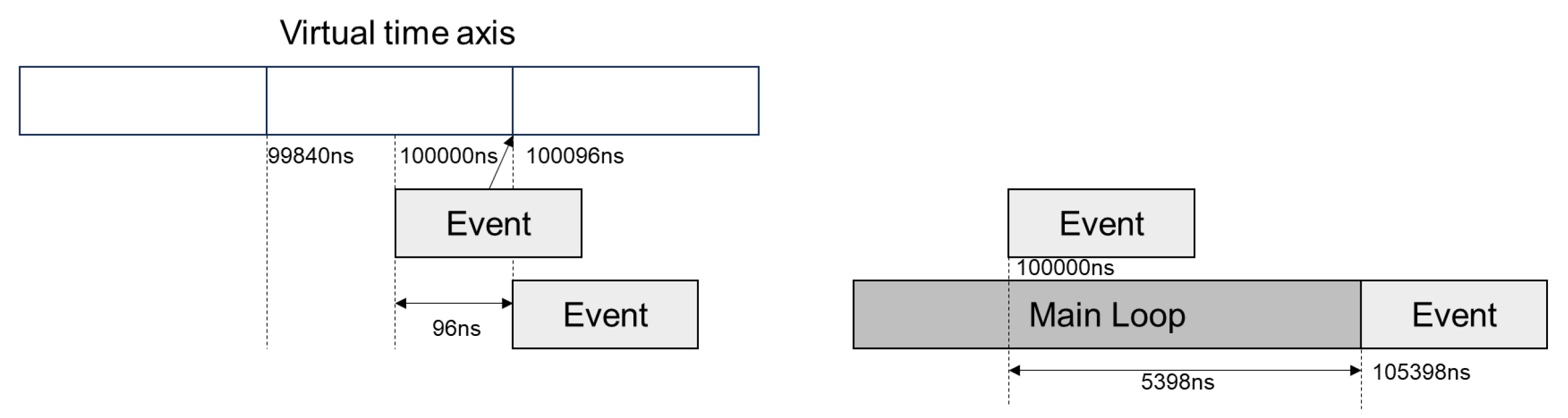
Taking a time-to-next message with timing of 100 µs as an example: after optimization, the expiration time is 100,096 ns with latency of 96 ns, producing a 96 ns error due to alignment with the virtual timeline grid, meeting timing resolution requirements; the traditional method’s expiration time is 105,398 ns with latency of 5398 ns, introducing a 5389 ns error from system scheduling, not meeting requirements.
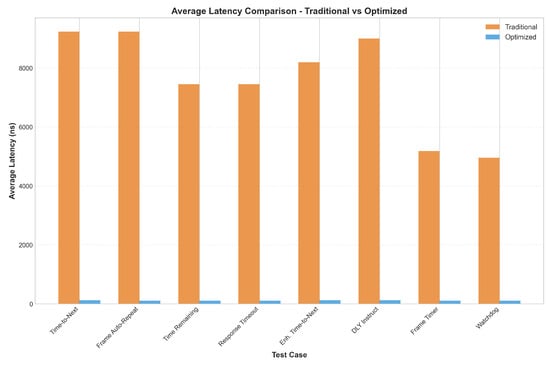
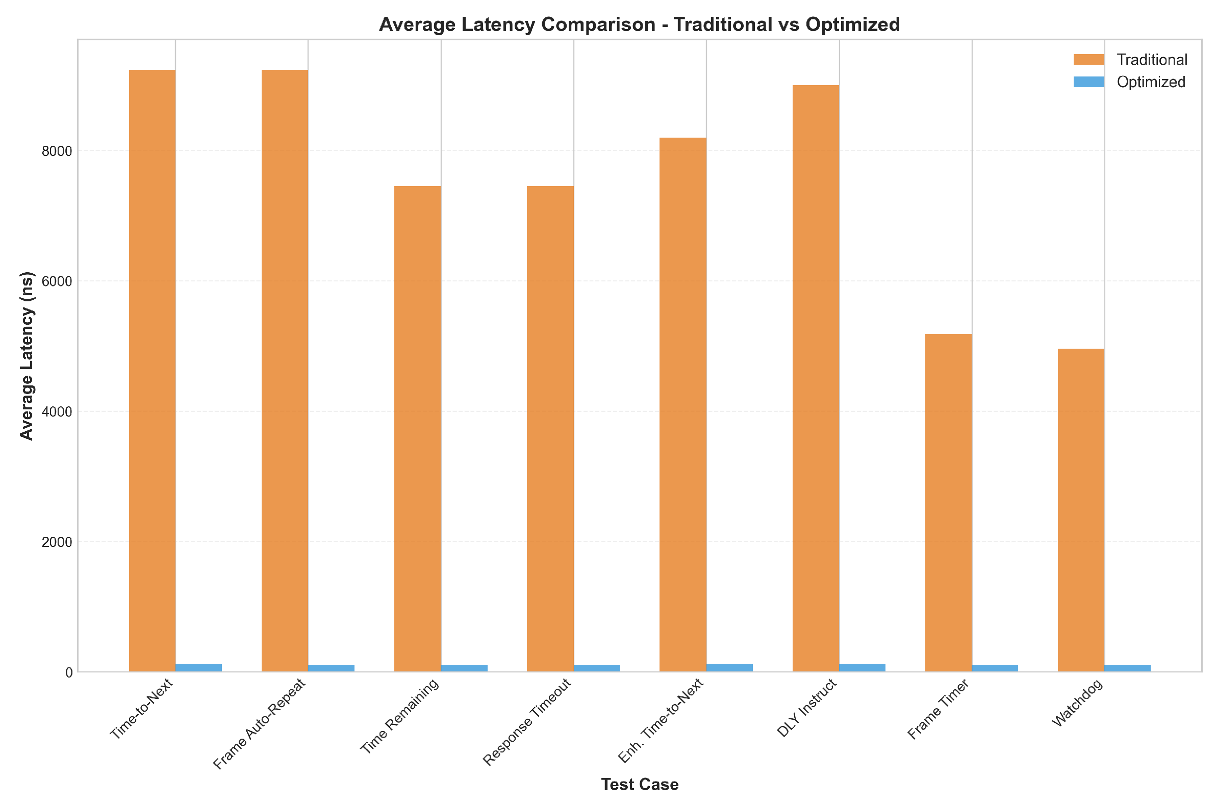
Figure 7 presents the average-latency comparison across all 10 scenarios, showing that the optimized method remains in the 112–124 ns range while the traditional method stays in the microsecond range.
Figure 7.
Average latency comparison between traditional and optimized methods across 10 test scenarios. Traditional method shows average latencies from 5181 to 9239 ns, while the optimized method maintains consistently low average latencies between 112 and 124 ns, representing a 98.6–98.7% improvement.
Table 3 presents comprehensive timing statistics for all 10 test scenarios, comparing the traditional and optimized methods with full statistical metrics including minimum, maximum, mean, median, standard deviation, and range.
Table 3.
Comprehensive timing statistics for all 10 test scenarios (values in ns).
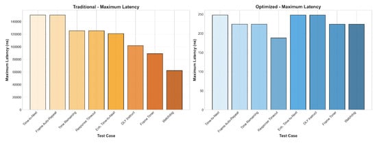
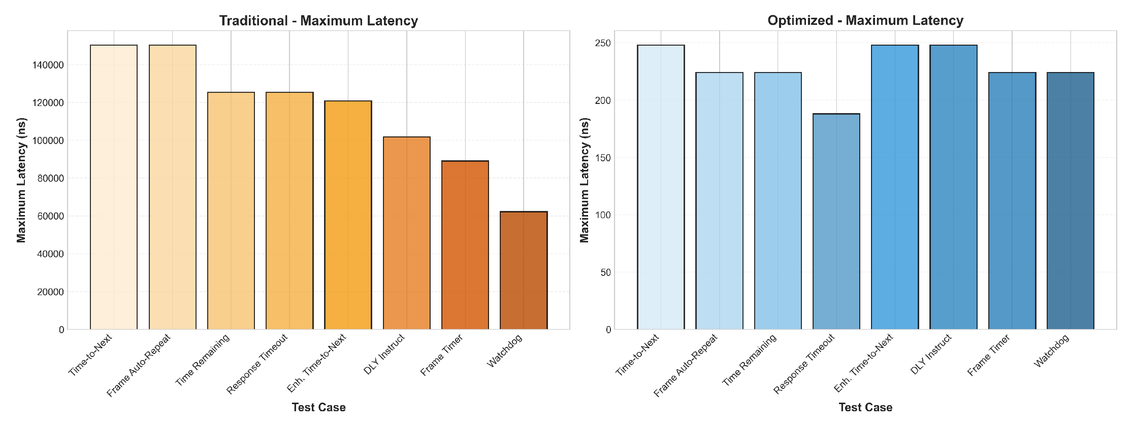
Figure 8 shows the maximum-latency comparison, where the optimized method is consistently below 250 ns while the traditional method reaches tens to hundreds of microseconds.
Figure 8.
Maximum latency comparison between traditional and optimized methods. Traditional data shows maximum latencies from 62,222 to 150,320 ns, while the optimized data maintains consistently low maximum latencies between 188 and 248 ns, representing a 99.8% reduction.
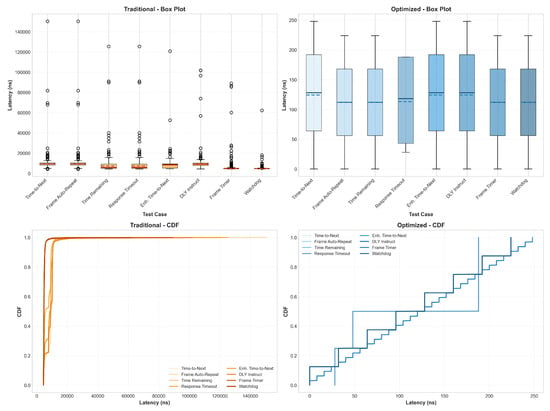
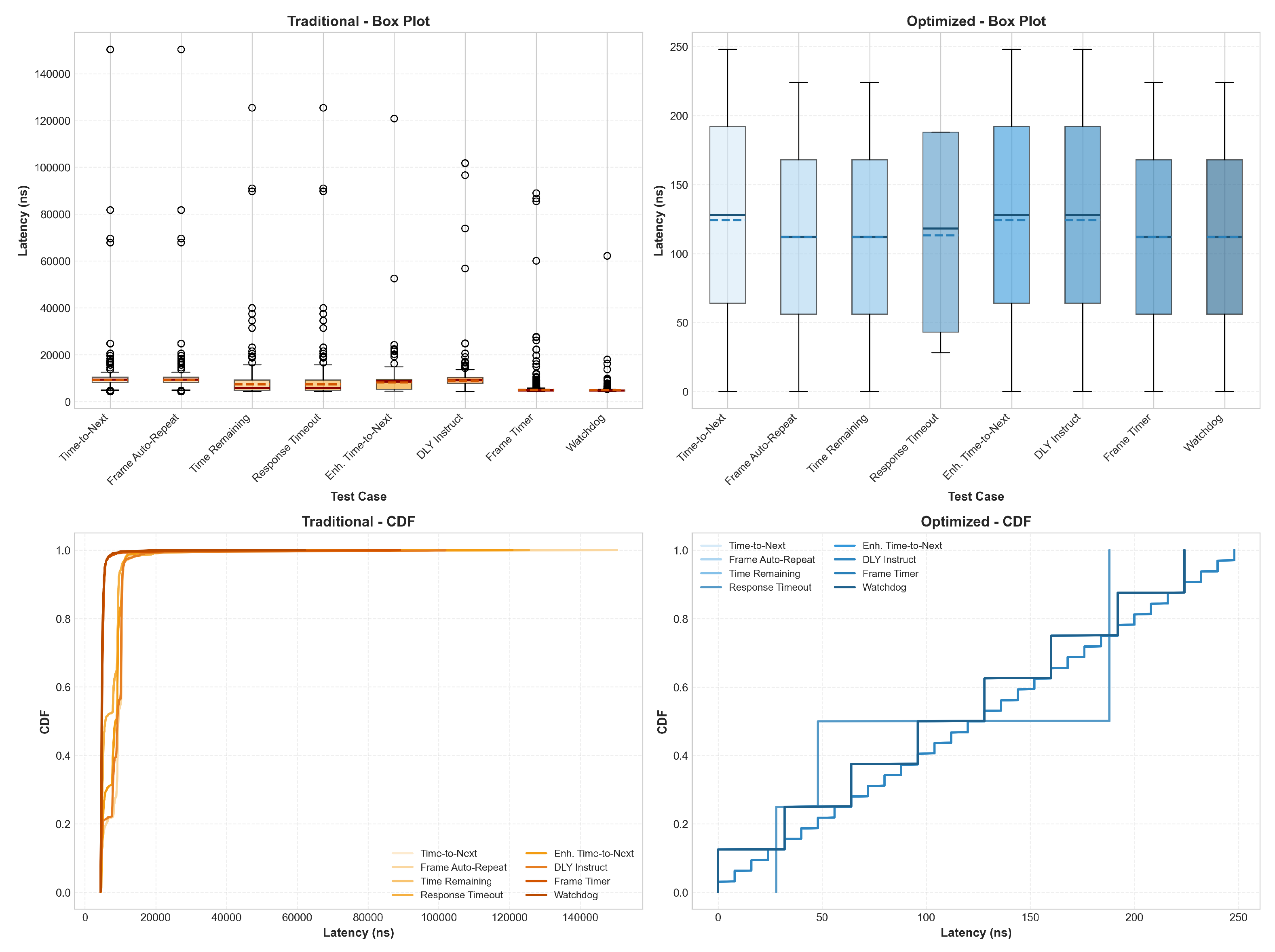
As shown in Figure 9 and Figure 10, the experimental results demonstrate substantial timing improvements. Figure 9 shows that the traditional method exhibits maximum latencies ranging from 62,222 to 150,320 ns across all 10 test scenarios, while our optimized method maintains consistently low maximum latencies between 188 and 248 ns, representing a 250–800× improvement.
Figure 9.
Comprehensive latency analysis using box plots and cumulative distribution functions. In this figure, blue denotes optimized data and orange denotes traditional data. In the box plot, solid lines denote medians and dashed lines denote means. In the CDF panel, overall trend comparison is the primary objective, and line overlap does not affect scientific conclusions. Only three visible curves are observed because optimized results are highly consistent across test cases and multiple curves overlap (eight curves in total).
Figure 10.
Concrete example illustrating latency sources: the optimized case (left) aligns Event to 100,000 ns on the virtual timeline and shows 96 ns delay, while the traditional case (right) shows a measured delay of 5398 ns due to main-loop scheduling. In this figure, white denotes the Virtual time axis, light gray denotes Event, and dark gray denotes Mainloop. The arrow at Event in the left panel indicates that Event is aligned to 100,000 ns, resulting in a 96 ns delay.
As presented in Figure 10, the optimized method achieves average latencies between 65 and 124 ns across all test types, compared to the traditional method’s average latencies ranging from 5000 to 15,000 ns. This dramatic reduction of 98.6–99.3% demonstrates the effectiveness of the virtual time-driven approach in eliminating timing uncertainty caused by host execution variations.
The above experimental results demonstrate that by explicitly modeling key timing behaviors as virtual time events, time deviations introduced by execution uncertainty in traditional simulation can be effectively eliminated, providing a reliable time foundation for high-credibility simulation and verification of the 1553B protocol.
Overhead Analysis: As shown in Table 3, the optimized method achieves average latencies from 65 to 124 ns across all 10 test scenarios, with an overall mean of approximately 111 ns. This overhead comes from virtual time event queue management and scheduling. Timing errors do not accumulate across successive events: each event’s deadline is computed from the absolute protocol timebase (i.e., the scheduled virtual time), not relative to the previous event’s actual firing time. The quantization error for each event is therefore independently bounded by at most ns, and the drift at the end of a frame remains bounded by a single rather than growing as . Our experimental data confirm this: the maximum observed latency across all scenarios is 248 ns (Table 3), consistent with single-event quantization rather than accumulated drift. In typical 1553B simulation configurations, the number of concurrently active timers is small (typically ≤ 5), so the event queue management overhead is negligible.
6. Discussion
6.1. Appropriateness of QEMU for Timing-Sensitive Simulation
A common concern regarding QEMU-based timing simulation is that QEMU operates on virtual time rather than wall-clock time. However, this characteristic is precisely what enables deterministic timing reproduction. In QEMU’s icount mode, virtual time advances in lockstep with the number of executed guest instructions, creating a fully deterministic timebase that is independent of host CPU speed, scheduling jitter, or system load. Unlike software-only protocol simulators that rely on host timers, our approach guarantees that identical guest code always produces identical timing sequences—a property essential for repeatable verification.
Beyond deterministic timing, QEMU offers three additional advantages that pure protocol simulators cannot provide. First, QEMU performs full-system emulation encompassing CPU, memory controller, interrupt subsystem, and peripheral devices within a single platform, enabling closed-loop execution of real device drivers and operating systems alongside the bus controller model. This allows validation of complete software stacks rather than isolated protocol logic. Second, QEMU’s broad device model ecosystem facilitates rapid construction of multi-node verification environments (e.g., BC–RT–MT topologies) by composing existing platform components, reducing integration effort compared to building dedicated simulation frameworks from scratch. Third, the entire simulation runs on commodity hardware without requiring any physical bus interface chips, enabling fully reproducible experiments on any host machine—a practical advantage for collaborative development and regression testing.
6.2. Generalizability to Other Protocols and Hardware-in-the-Loop (HIL) Environments
Although this paper focuses on MIL-STD-1553B as the target protocol, the core mechanisms of the proposed method are protocol-agnostic. Three foundational components, icount-based deterministic execution, virtual time event scheduling with deadline-driven callback dispatch, and quantization grid alignment, operate independently of any particular protocol’s timing semantics. These components form a reusable timing infrastructure that can be adapted to other communication protocols requiring microsecond-level or sub-microsecond timing fidelity.
The protocol-specific aspect of our approach lies in the timing semantic mapping: translating a protocol’s timing requirements into virtual time events. For MIL-STD-1553B, this involves modeling intermessage gaps, response timeouts, retry windows, and frame boundaries. Other protocols would require different mappings: CAN bus requires arbitration delay and bit-timing modeling; TTEthernet requires time-triggered scheduling windows and clock synchronization semantics; ARINC 429 requires inter-word gaps and transmission rate control. In each case, the underlying virtual time infrastructure remains unchanged, while only the protocol adaptation layer needs to be redesigned.
MIL-STD-1553B was selected as the validation case because its strict microsecond-level timing constraints (e.g., 4–12 µs intermessage gaps, 12 µs response timeouts) impose demanding requirements on any simulation platform. Achieving sub-microsecond timing fidelity for 1553B provides strong evidence that the same infrastructure can accommodate protocols with comparable or relaxed timing requirements. We envision a two-layer architecture—a protocol-agnostic virtual time framework coupled with protocol-specific adaptation modules—as the natural extension of this work.
6.3. Limitations
Several limitations of the current work should be noted.
Our implementation focuses on deterministic, schedule-driven message scenarios and does not handle asynchronous event contention or multi-master bus arbitration, which are relevant to certain advanced 1553B application profiles.
The experimental evaluation validates the determinism and internal consistency of the virtual time mechanism but does not include direct comparison with a physical BU-64843 chip. We were unable to obtain this chip for equivalent test bench measurements during this study. While our model shows highly deterministic timing behavior (65–124 ns deviation), we cannot rule out the possibility of systematic bias. The model’s accuracy depends on faithful implementation of protocol timing semantics as specified in MIL-STD-1553B; physical hardware measurements are needed to validate absolute accuracy and quantify any systematic offset.
The virtual time mechanism introduces approximately 65–124 ns average overhead for event scheduling and processing. Importantly, this overhead remains stable across different RT counts and message densities and does not accumulate over successive events, since each deadline is computed from the absolute protocol timebase. Nevertheless, this overhead may matter for applications requiring sub-microsecond timing granularity, although it comfortably satisfies the 1553B protocol’s 1 µs minimum resolution requirement.
Finally, the current model assumes idealized bus behavior and does not account for electrical signal propagation delays or physical layer effects that may become significant in high-speed or long-distance bus configurations.
7. Conclusions
This paper addressed the challenge of achieving deterministic reproduction of 1553B microsecond-level timing semantics in QEMU-based virtualization platforms. We proposed a unified BU-64843 device model supporting BC/RT/MT multi-role switching and implemented behavioral modeling for both legacy and enhanced bus controllers. The virtual time-driven precise timing modeling method explicitly models key timing semantics as discrete events on a virtual timeline. Extensive experiments across 10 timing scenarios demonstrate that our method reduces timing deviation from an average of 8 µs to 65–124 ns (99.1% improvement), achieving deterministic simulation decoupled from host execution speed while meeting the 1 µs minimum resolution requirement.
Future Work: Several directions remain for further investigation. The most immediate priority is validating our model against a physical BU-64843 (or equivalent DDC BU-61580) chip on a hardware test bench, directly comparing simulated timing with physical measurements to quantify any systematic bias and calibrate model parameters. A second direction is abstracting the virtual time-driven approach into a generic timing framework within QEMU to support other communication protocols with strict timing requirements—while the core mechanisms (event scheduling on a virtual timeline, icount deterministic execution, grid quantization) are protocol-agnostic, each protocol requires specific timing semantic mappings: CAN requires arbitration and bit-timing modeling, TTEthernet requires time-triggered scheduling and synchronization window semantics, and ARINC 429 requires word-gap and rate control. Additional directions include extending the unified device model to support other 1553B chip variants (e.g., BU-61580, ACE series) for broader hardware platform coverage, integrating cycle-accurate CPU models to analyze cross-layer timing interactions between software execution and bus communication, developing automated test case generation and protocol compliance verification tools based on the precise timing model, and conducting host-stress sweep experiments (e.g., using stress-ng to saturate host CPU and memory) to further validate the robustness of icount-based decoupling under varying host conditions.
Author Contributions
Conceptualization, W.L.; Methodology, H.G.; Software, Y.F., W.Y. and X.G.; Validation, Y.F., W.Y. and X.G.; Investigation, H.G.; Resources, W.L.; Data curation, H.G.; Writing—original draft preparation, H.G.; Writing—review and editing, H.G. and W.L.; Visualization, H.G.; Supervision, W.L.; Project administration, H.G.; Funding acquisition, W.L. All authors have read and agreed to the published version of the manuscript.
Funding
This research received no external funding.
Institutional Review Board Statement
Not applicable.
Informed Consent Statement
Not applicable.
Data Availability Statement
The data presented in this study are available in this article.
Acknowledgments
The authors would like to thank all those who contributed to this research.
Conflicts of Interest
The authors declare no conflicts of interest.
Abbreviations
The following abbreviations are used in this manuscript:
| BC | Bus Controller |
| RT | Remote Terminal |
| MT | Monitor Terminal |
| HIL | Hardware-in-the-Loop |
| QEMU | Quick Emulator |
| DDS | Data Distribution Service |
References
- Deniz, E.; Durak, U.; Güçlü, K.; Oguztuzun, H. DDS based MIL-STD-1553B Data Bus interface simulation. J. Def. Model. Simul. 2014, 12, 179–188. [Google Scholar] [CrossRef] [Scilit]
- Engblom, J.; Holm, C. A Fully Virtual Multi-Node 1553 Bus Computer System. In Proceedings of the 2006 IEEE/EWE/IFAC International Conference on Methods and Techniques for Diagnostics of Complex Industrial Systems; IEEE: New York, NY, USA, 2006; pp. 1–5. [Google Scholar]
- Zabolotny, W. QEMU-based hardware/software co-development for DAQ systems. J. Instrum. 2022, 17, C04004. [Google Scholar] [CrossRef] [Scilit]
- Jünger, L.; Weinstock, J.H.; Jassi, M.; Yoshinaga, M.; Hamao, H.; Sato, K. Virtual ECUs with QEMU and SystemC TLM-2.0: The best of both worlds. In Proceedings of the DVCon Europe 2023 Conference and Exhibition, Munich, Germany, 14–15 November 2023; pp. 1–8. [Google Scholar]
- Späthe, S.; Schirrmeister, B.; Geyer, F. Simulation and Benchmarking of IoT Device Usage Scenarios Using Zephyr and Qemu. In Proceedings of the 14th International Conference on Smart Homes and Health Telematics; Springer: Berlin/Heidelberg, Germany, 2020; pp. 1–10. [Google Scholar]
- Decker, J.; Hasse, V.F.; Kunkel, J. Q8S: Emulation of Heterogeneous Kubernetes Clusters Using QEMU. Algorithms 2025, 18, 324. [Google Scholar] [CrossRef] [Scilit]
- Poduval, K. Virtual Memory to Memory Scaler Hardware Device Using QEMU. Int. J. Sci. Res. 2022, 11, 1507–1509. [Google Scholar] [CrossRef] [Scilit]
- Efimov, V.Y.; Bezzubikov, A.A.; Bogomolov, D.A.; Goremykin, O.V.; Padaryan, V. Automation of device and machine development for QEMU. Proc. Inst. Syst. Program. RAS 2017, 29, 77–104. [Google Scholar] [CrossRef] [Scilit] [PubMed]
- Spensky, C.; Machiry, A.; Redini, N.; Unger, C.; Foster, G.; Blasband, E.; Okhravi, H.; Kruegel, C.; Vigna, G. Conware: Automated Modeling of Hardware Peripherals. In Proceedings of the 2021 Network and Distributed System Security Symposium (NDSS); NDSS: San Diego, CA, USA, 2021; pp. 95–109. [Google Scholar] [CrossRef] [Scilit]
- Ma, Z.; Liu, Q.; Li, Z.; Yin, T.; Tan, W.; Zhang, C.; Payer, M. Truman: Constructing Device Behavior Models from OS Drivers to Fuzz Virtual Devices. In Proceedings of the 2025 Network and Distributed System Security Symposium (NDSS); NDSS: San Diego, CA, USA, 2025; pp. 1–18. [Google Scholar] [CrossRef] [Scilit]
- Cao, Y.; Xu, Z.; Tan, Z. QEMU-CAS: A Full-System Cycle-Accurate Simulation Framework based on QEMU. In Proceedings of the Workshop on Computer Architecture Research with RISC-V (CARRV), Orlando, FL, USA, 17–21 June 2023; pp. 1–7. [Google Scholar]
- Wu, L.; Hong, W.; Ou, Y.; Wang, Z.; Gao, S. CXL-DMSim: A Full-System CXL Disaggregated Memory Simulator with Comprehensive Silicon Validation. In Proceedings of the IEEE Transactions on Computer-Aided Design of Integrated Circuits and Systems; IEEE: New York, NY, USA, 2025. [Google Scholar] [CrossRef] [Scilit]
- Yeh, T.-C.; Chiang, M.-C. On the interface between QEMU and SystemC for hardware modeling. In Proceedings of the 2010 International Symposium on Next-Generation Electronics (ISNE), Kaohsiung, Taiwan, 18–19 November 2010; IEEE: New York, NY, USA, 2010; pp. 490–493. [Google Scholar] [CrossRef] [Scilit]
- Biagetti, G.; Falaschetti, L.; Crippa, P.; Alessandrini, M.; Turchetti, C. Open-Source HW/SW Co-Simulation Using QEMU and GHDL for VHDL-Based SoC Design. Electronics 2023, 12, 3986. [Google Scholar] [CrossRef] [Scilit]
- Díaz, E.; Mateos, R.; Bueno, E.J.; Nieto, R. Enabling Parallelized-QEMU for Hardware/Software Co-Simulation Virtual Platforms. Electronics 2021, 10, 759. [Google Scholar] [CrossRef] [Scilit]

Disclaimer/Publisher’s Note: The statements, opinions and data contained in all publications are solely those of the individual author(s) and contributor(s) and not of MDPI and/or the editor(s). MDPI and/or the editor(s) disclaim responsibility for any injury to people or property resulting from any ideas, methods, instructions or products referred to in the content. |
© 2026 by the authors. Licensee MDPI, Basel, Switzerland. This article is an open access article distributed under the terms and conditions of the Creative Commons Attribution (CC BY) license.