


Abstract
To mitigate the inertia deficiency and weak damping in receiving-end grids caused by the large-scale integration of the offshore wind power-integrated MMC-HVDC system, this paper proposes a coordinated inertia support strategy. First, the transient support capability of submodule capacitors within the HVDC system is quantitatively analyzed. Subsequently, a capacitor energy-based grid-forming control is developed. A decoupled control mechanism is implemented to eliminate the coupling between submodule capacitor voltage and DC voltage, enabling maximum utilization of the converter’s internal transient energy while maintaining DC voltage stability. Furthermore, by introducing a frequency deadband mechanism, a coordinated inertia support strategy mediated by DC voltage is established. This facilitates a hierarchical support sequence wherein capacitors prioritize responses to minor disturbances, while the offshore wind farm (OWF) participates cooperatively during severe frequency deviations. PSCAD/EMTDC 4.6.2 simulations demonstrate that the proposed strategy achieves optimal capacitor energy utilization and effective multi-entity coordination. It reduces the maximum deviation in the grid by 33.3%, significantly enhancing system frequency stability.
1. Introduction
Driven by the accelerated global energy transition, the renewable energy sector has experienced an explosive growth trajectory [1,2]. Offshore wind power, a critical driver of this low-carbon transformation, benefits from abundant resources, high capacity factors, and minimal land-use constraints. As nearshore development approaches saturation, the industry is rapidly expanding into deep-sea and far-offshore regions. To address the challenges of long-distance, large-capacity power aggregation and transmission inherent to these environments, high-voltage direct current (HVDC) transmission based on modular multilevel converters (MMCs) has emerged as the prevailing solution. Due to its decoupled active and reactive power control, rapid dynamic response, and robust scalability, MMC-HVDC is particularly well-suited for large-scale offshore wind power integration [3,4].
However, the high penetration of renewable energy sources poses significant challenges to the secure and stable operation of power systems [5,6,7]. The large-scale displacement of conventional synchronous generators has fundamentally altered the physical characteristics of receiving-end grids, resulting in low inertia and weak damping, which significantly diminishes the system’s disturbance rejection capability. Furthermore, under conventional control schemes, HVDC transmission systems decouple the frequency dynamics between sending- and receiving-end grids. This prevents sending-end converters and wind turbines from responding to receiving-end frequency variations, exacerbating the risk of frequency instability [8,9,10]. Consequently, investigating autonomous frequency-response mechanisms for HVDC transmission and harnessing the coordinated regulation potential of diverse resources is imperative to ensure the reliability of future high-renewable power systems.
To enhance the inertia support capability of HVDC systems, existing research primarily focuses on two dimensions: coordinated control based on AC system coupling and independent control based on converter station energy storage.
The core objective of AC system coupling is to synthesize a connection between the renewable generation side and the grid, enabling sending-end units to detect and respond to frequency perturbations. Depending on their signaling dependencies, these strategies are categorized as communication-based and communication-free. Communication-based strategies transmit frequency signals to the sending end via dedicated channels to trigger inertia support [11,12,13]. However, latency and packet loss, which escalate with transmission distance, severely compromise control reliability. To circumvent these issues, communication-free strategies have been proposed [14,15,16].
In these approaches, the receiving-end converter employs droop control to map frequency deviations to DC voltage variations, which subsequently modulate the sending-end frequency. While this effectively addresses the “source–grid” decoupling, the DC system serves primarily as a transmission medium, leaving the transient inertia support potential of the converter station’s internal energy storage underutilized.
To overcome the limitations of coordinated strategies, independent control based on converter station energy storage has gained significant attention. These methods leverage the electrostatic energy stored in MMC submodule capacitors to provide rapid inertia support to the grid. Research [17,18] proposes actively regulating the DC voltage to emulate the kinetic energy of synchronous generator rotors. However, the strong coupling between the submodule capacitor voltage and DC voltage rigidly constrains energy utilization within the safe operating range. To enhance flexibility, multi-level power support modes based on allowable DC voltage deviations are defined in [19,20,21], while adaptive damping and inertia coefficients are introduced in [22]. Nevertheless, these approaches do not fundamentally eliminate the voltage coupling constraint. To address this, active energy control strategies proposed in [23,24,25] decouple the submodule capacitor voltage from the DC voltage. This significantly expands the usable energy margin and enhances control freedom. However, MMC submodule capacitors are short-term storage elements with millisecond-level dynamics and finite capacity [26]. Consequently, independent strategies relying solely on internal converter energy prove insufficient for mitigating severe frequency disturbances caused by substantial power imbalances.
While both coordinated and independent control strategies play important roles in inertia support, traditional research often investigates them in isolation, neglecting the necessary coordination between the two. This lack of synergy leads to a severe underutilization of the capacitor energy storage within the MMC-HVDC system. Consequently, there is an urgent need for an effective coordinated control strategy to maximize capacitor energy utilization, thereby alleviating the inertia support burden on the OWF.
In response to these challenges, this paper proposes a coordinated inertia support strategy for the offshore wind power-integrated MMC-HVDC system. First, the transient support capability of the HVDC system is quantitatively analyzed. Subsequently, a capacitor energy-based grid-forming control is developed, incorporating a decoupled control mechanism to maximize the utilization of capacitor energy. Furthermore, a coordinated inertia support strategy involving multiple support entities is proposed, utilizing the DC voltage as the coupling medium. Finally, the feasibility and effectiveness of the proposed strategy are validated in PSCAD/EMTDC 4.6.2.
The paper is organized as follows: Section 2 describes the system topology and analyzes its transient support capability. Section 3 details the principle of the capacitor-energy-based grid-forming control strategy. Section 4 presents the proposed decoupled control strategy for capacitor energy and DC voltage. Section 5 proposes the coordinated inertia support strategy involving the MMC-HVDC and the OWF. Section 6 validates the effectiveness of the proposed strategy. Section 7 discusses the proposed control strategy. Finally, conclusions are drawn in Section 8.
2. System Characteristics
2.1. Topological Structure
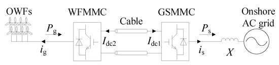
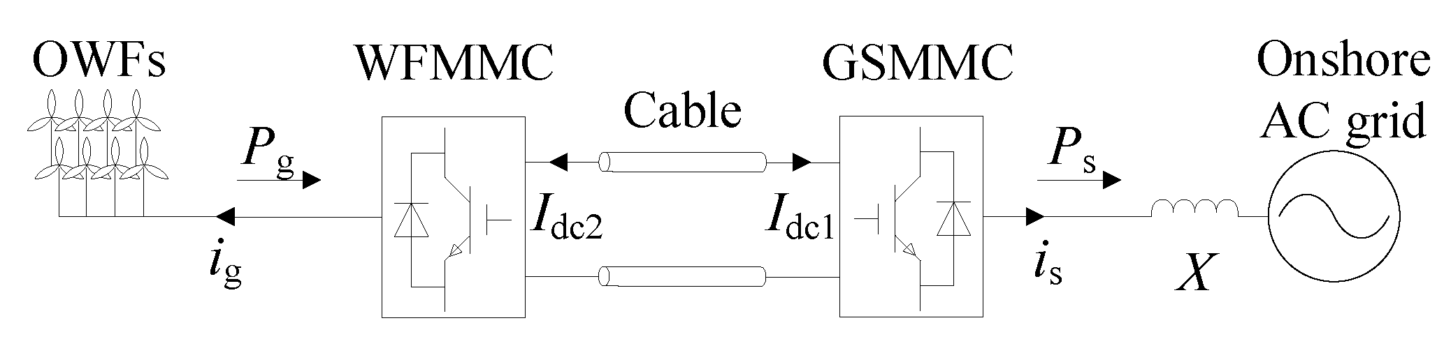
The topology of the offshore wind power-integrated MMC-HVDC system is illustrated in Figure 1. The system comprises an offshore wind farm (OWF), wind farm side MMC (WFMMC), grid side MMC (GSMMC), DC cables, and the onshore AC grid. Power generated by the OWFs is collected locally and transmitted to the onshore AC grid. The HVDC system adopts a pseudo bipolar point-to-point connection, in which both converter stations utilize half-bridge submodules (HBSMs). The main system parameters are listed in Table 1.
Figure 1.
Topology of the offshore wind power-integrated MMC-HVDC system.
Table 1.
Parameters of the offshore wind power-integrated MMC-HVDC system.
2.2. Transient Support Capability Analysis
Both the WFMMC and GSMMC of the HVDC system contain substantial energy storage elements. These include submodule capacitors, arm inductors, and the equivalent inductance of the DC cables. Energy is stored as electrostatic energy in capacitors and as magnetic field energy in inductors. By utilizing the inherent energy storage capabilities, the HVDC system is capable of providing inertia support to the grid. The magnetic field energy stored in the inductive elements is determined by the DC current and the equivalent inductance. However, the magnitude of the magnetic field energy is typically much smaller than the electrostatic energy. Consequently, the contribution of inductive energy can be considered negligible [22]. Accordingly, this paper focuses exclusively on the transient support capability provided by the submodule capacitors in the HVDC system.
Under rated operating conditions, the total rated capacitor energy for both the WFMMC and the GSMMC is expressed as:
where Csm is the submodule capacitance, N is the number of submodules per arm, and Ucn is the rated operating voltage of each submodule capacitor.
The energy margin of a capacitor is defined as the difference between its maximum permissible stored energy and its rated energy. Consequently, the available energy margin of the submodule capacitors within the HVDC system is given by:
where Uclim is the voltage limit of the submodule capacitor.
To ensure transmission reliability, a sufficient voltage margin is typically reserved during the selection of submodule capacitors. According to established engineering practices for HVDC systems, the rated voltage of a submodule capacitor is typically selected to be approximately 1.4 times its nominal operating voltage. Furthermore, submodule capacitors possess overvoltage tolerance capability. As specified in IEC61071, capacitors can withstand 1.15 times their rated voltage for a continuous duration of 30 min. Consequently, the maximum short-term tolerable voltage of a submodule capacitor is Ucmax = 1.61 Ucn. Given that the software overvoltage protection threshold for switching devices is typically set at 1.6 Ucn, the maximum short-term tolerable capacitor voltage is conservatively defined as 1.5 times the rated operating voltage. Under this condition, the maximum energy absorption margin of the capacitor is expressed as:
3. Capacitor Energy-Based Grid-Forming Control
In the offshore wind power-integrated MMC-HVDC system, GSMMC typically utilizes grid-following current vector control to maintain a constant DC voltage. However, as the penetration of renewable energy increases, the short-circuit ratio (SCR) of the grid diminishes. Consequently, the dynamic performance of the phase-locked loop in GSMMC deteriorates, potentially leading to oscillatory instability. Grid-forming control offers an effective solution for the challenges associated with weak-grid operation. Therefore, by establishing an analogy between the energy dynamics of GSMMC submodule capacitors and the rotor motion equation of synchronous generators, this paper proposes a capacitor energy-based grid-forming control strategy for GSMMC.
3.1. Self-Synchronizing Control Principle
The rotor motion equation of a synchronous generator can be expressed as:
where HSG is the inertia time constant of the synchronous generator, ω is the grid angular frequency, and Pm and Pe are the mechanical and electromagnetic powers, respectively.
The total energy stored in the submodule capacitors of GSMMC is calculated as:
where Uc is the average voltage of all submodule capacitors.
The rate of change in the submodule capacitor energy corresponds to the power imbalance between the DC and AC sides. The dynamic equation can be written as:
where Pdc and Pac are the DC power and AC power of the GSMMC, respectively.
By combining the aforementioned equations, the equivalent inertia model of GSMMC can be derived as:
where H is the equivalent inertia time constant of GSMMC. Integrating both sides of the above equation yields:
where ωn is the rated grid angular frequency, and is the reference value of the submodule capacitor energy.
To improve system stability, a capacitor energy feedforward term is introduced into the synchronization loop. Accordingly, the control law of the synchronization loop can be expressed as:
where kw is the capacitor energy droop coefficient, and ks is the feedforward coefficient. By establishing a coupling relationship between the phase angle at the point of common coupling (PCC) and the submodule capacitor energy, grid synchronization is achieved without the phase-locked loop. Under this condition, the converter output angular frequency is given by:
Consequently, the equivalent inertia time constant of GSMMC is derived as:
As indicated by (11), the droop coefficient is inversely proportional to the equivalent inertia time constant. Therefore, a smaller droop coefficient corresponds to a greater inertia support capability for the system.
3.2. Dynamic Response Characteristics
Due to the coupling relationship between the submodule capacitor energy and the phase angle at the PCC, the capacitor energy inherently tracks the frequency of the onshore AC grid. In the event of a grid disturbance, the frequency of GSMMC deviates from the rated grid frequency. Consequently, the capacitor energy fluctuates in response to the frequency deviation. Given that the total number of inserted submodules in the upper and lower arms of each phase remains constant at N, the DC voltage satisfies:
Combining (5) and (12) yields:
The capacitor energy is directly proportional to the square of the DC voltage. Thus, an inherent coupling exists between the DC voltage and the submodule capacitor energy. Consequently, during grid frequency disturbances, the DC voltage varies in correlation with the grid frequency. Under these conditions, the output power of GSMMC is expressed as:
where Uv and θv are the voltage magnitude and phase angle at the PCC, respectively, while Us and θs are the voltage magnitude and phase angle of the onshore AC grid. Furthermore, X is the sum of the equivalent reactance between the PCC and the onshore grid, and δ denotes the power angle.
Following a decrease in the onshore AC grid load, the grid frequency rises, resulting in a decrease in the power angle. Consequently, the power delivered by GSMMC is reduced. Given that the output power of the OWFs remains constant, the GSMMC operates in a state of power imbalance. As a result, the surplus energy accumulates within the submodule capacitors. Governed by the proposed capacitor energy-based grid-forming control, GSMMC output angular frequency increases correspondingly until resynchronization with the grid is achieved. Conversely, an increase in the onshore grid load causes the grid frequency to drop and the power angle to increase. This leads to an increase in power injection from GSMMC to the onshore AC grid. Due to this power deficit, the energy stored in the submodule capacitors is depleted. Driven by the grid-forming control, the GSMMC output angular frequency decreases until synchronization with the grid is restored.
4. Decoupled Control Strategies
Due to the inherent coupling among the submodule capacitor energy, DC voltage, and grid frequency, both the capacitor energy and DC voltage fluctuate in response to grid frequency variations. Leveraging this characteristic, WFMMC can derive grid frequency information solely by monitoring the DC voltage. Consequently, it can adjust the output power of the OWFs to provide inertia support without the need for communication links. However, this coupling strategy compromises the flexibility of DC voltage control. The limitation manifests primarily in two ways. First, any variations in either the AC-side or DC-side power of GSMMC inevitably induce DC voltage fluctuations. Second, in established engineering practices, DC voltage deviation is typically constrained to within 10%. During grid frequency variations, the submodule capacitor voltage deviation must similarly be restricted to approximately 10% to ensure safe and stable operation. Consequently, this constraint limits the inertia support capability of the submodule capacitors, preventing the full utilization of the converter station’s inherent energy margin. To address these limitations, this paper proposes a decoupled control strategy.
4.1. DC Voltage Control of GSMMC
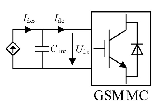
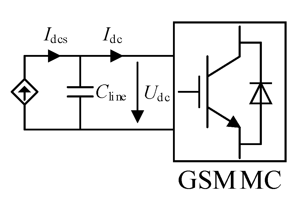
When GSMMC utilizes capacitor energy-based grid-forming control for self-synchronization, the DC system and DC cables are modeled as a DC current source Idcs in parallel with an equivalent line capacitance Cline, as illustrated in Figure 2. Accordingly, the dynamic equation governing the relationship between the DC voltage and the DC current is expressed as:
Figure 2.
Equivalent DC circuit of GSMMC.
Neglecting the disturbance term Idcs, the DC voltage outer-loop controller for GSMMC is designed as:
where Udc1 and Udc1* are the measured and reference values of the GSMMC DC voltage, respectively, while kp1 and ki1 are the proportional and integral gains of the PI controller.
Let mdc and mac denote the DC and AC modulation indices, respectively. Accordingly, the voltages of the upper and lower arms are expressed as:
where Udcn is the rated DC voltage, and φj is the power factor angle.
The current dynamic of the phase unit satisfies:
where L0 is the arm inductance, icj is the circulating current of phase j, and ucomj represents the common-mode voltage of the upper and lower arms of phase j.
Combining (17) and (18) yields:
Summing the equations across the three phases and incorporating , the following expression is derived:
Consequently, the DC current inner-loop controller is designed as:
where kp2 and ki2 are the proportional and integral gains of the PI controller in the DC current control loop.
4.2. Capacitor Energy Control of WFMMC
In the offshore wind power-integrated MMC-HVDC system, WFMMC adopts a constant voltage and constant frequency control strategy to ensure stable operation for the OWFs. Accordingly, the dynamic of the submodule capacitor energy is expressed as:
where Wc2 is the total capacitor energy of WFMMC. Udc2 and Idc2 are the converter’s DC voltage and DC current, respectively, while Pdc2 and Pac2 correspond to its DC and AC power.
Dividing both sides of the equation by Udc2 yields:
Neglecting the disturbance term Pac2/Udc2, the capacitor energy outer-loop controller for WFMMC is designed as:
where Wc2* is the reference value of WFMMC capacitor energy, while kp3 and ki3 are the proportional and integral gains of the PI controller in the capacitor energy control loop.
Given that the design methodology for the WFMMC’s current inner-loop controller is analogous to that of GSMMC, its detailed derivation is omitted here for brevity. As established in the preceding analysis, WFMMC and GSMMC regulate the DC current based on DC voltage and capacitor energy, respectively. Furthermore, combining this with (15) reveals that capacitive current-to-ground ensures that the DC current control loops of WFMMC and GSMMC operate without conflict.
5. Coordinated Inertia Support Strategy
5.1. Inertia Support Strategy of Individual Entity
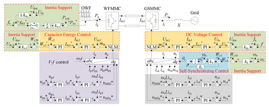
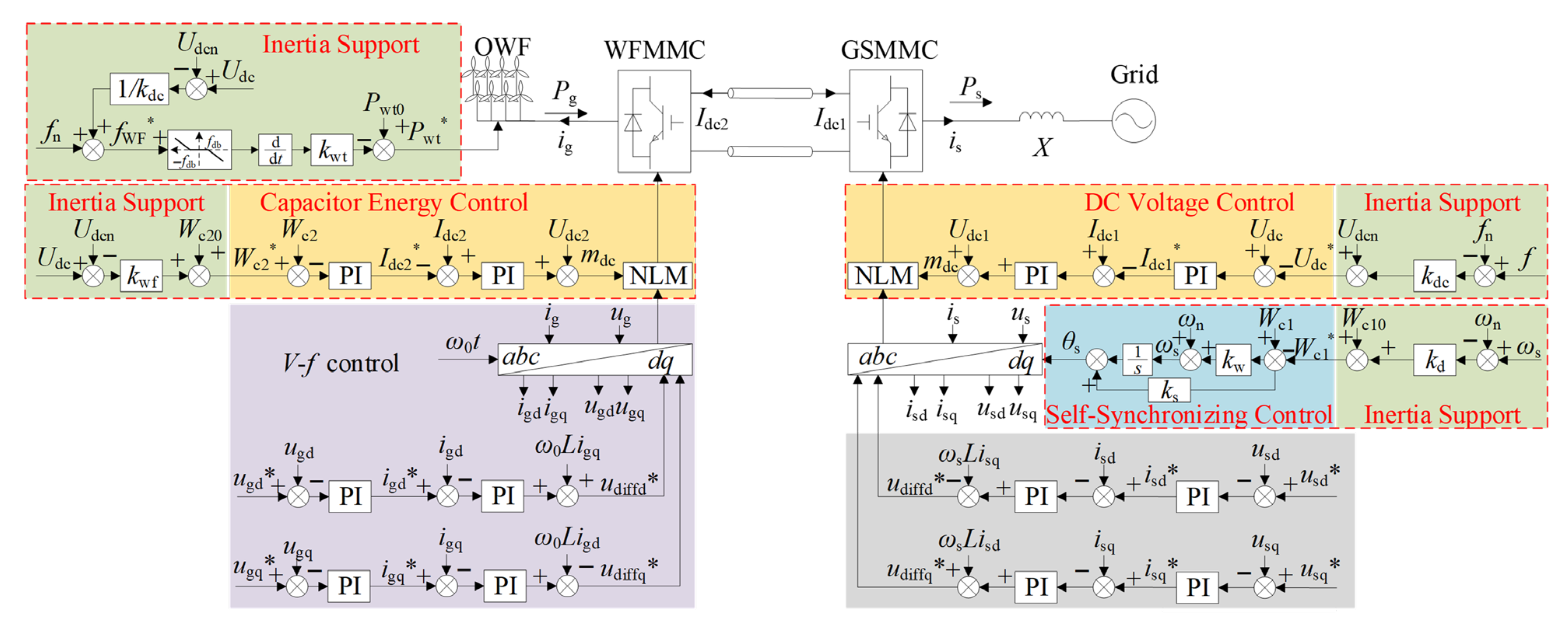
Under the decoupled control strategy, the number of inserted submodules in each phase becomes a controllable variable, determined by the DC modulation index. This control allows the submodule capacitor energy to be effectively decoupled from the DC voltage. Consequently, the offshore wind power-integrated MMC-HVDC system maintains stable operation while fully utilizing the energy stored in the submodule capacitors for inertia support. The overall control strategy for the offshore wind power-integrated MMC-HVDC system is shown in Figure 3.
Figure 3.
Overall control strategy of the HVDC system for offshore wind power. (The * in the figure denotes the reference value.)
5.1.1. Inertia Support of GSMMC
To fully utilize the energy margin of GSMMC submodule capacitors, a ω-Wc droop control is introduced into the submodule capacitor energy control loop. The reference value of the submodule capacitor energy is adjusted dynamically in response to variations in the onshore AC grid frequency. Accordingly, the reference value of the submodule capacitor energy is expressed as:
where denotes the steady-state reference value of GSMMC submodule capacitor energy, and kd is the ω-Wc droop coefficient.
Combining (8) and (25) yields:
Consequently, the equivalent inertia time constant of GSMMC is expressed as:
Comparing (11) and (27) reveals that the introduction of the droop control increases the inertia support capability of GSMMC by kd/2. Given that the submodule capacitor energy is limited, the selection of the droop coefficient must account for both the available energy margin and the energy required for self-synchronization:
where Δωclim is the maximum allowable angular frequency deviation.
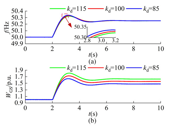
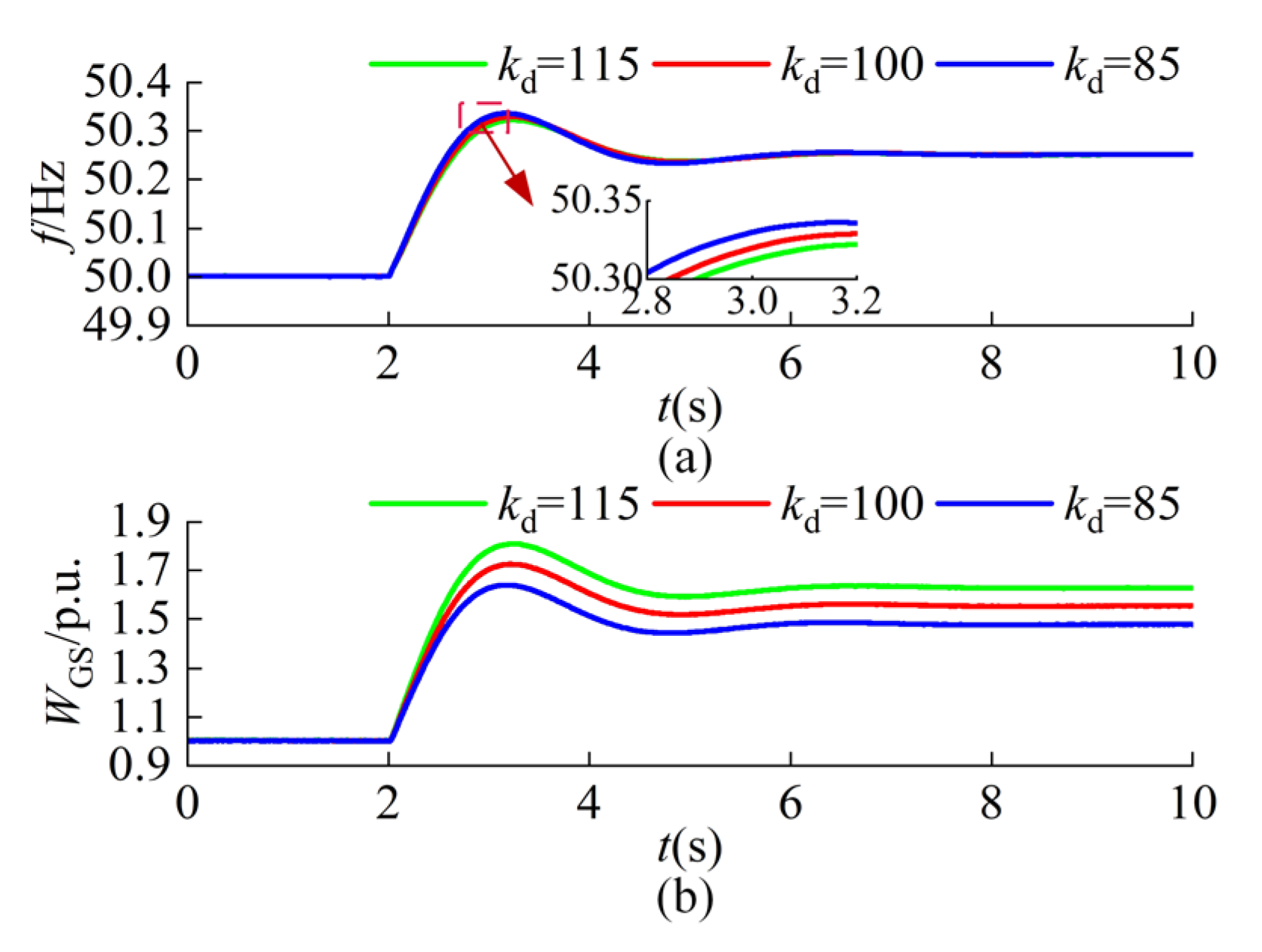
Figure 4 illustrates the dynamic responses of the grid frequency and GSMMC capacitor energy under varying droop coefficients. As the droop coefficient kd increases, the energy absorbed by GSMMC gradually increases while remaining strictly within its capacity limits. Consequently, the peak grid frequency is effectively reduced, demonstrating an enhanced inertia support capability. These observations perfectly align with the theoretical analysis.
Figure 4.
Dynamic characteristics under varying droop coefficient. (a) Grid frequency. (b) GSMMC capacitor energy.
5.1.2. Inertia Support of WFMMC
Both WFMMC and GSMMC utilize HBSMs and consequently possess identical submodule capacitor energy margins. However, under the decoupled control strategy, the DC voltage no longer inherently reflects the onshore AC grid frequency. As a result, WFMMC cannot directly detect real-time frequency variations in the grid. To enable the WFMMC submodule capacitor energy to contribute to inertia regulation, a f-Udc droop control loop is implemented in GSMMC and superimposed onto the DC voltage reference. This mechanism ensures that variations in the onshore AC grid frequency are intentionally mapped onto the DC voltage via the adjusted reference. Consequently, the DC voltage reflects grid frequency changes while maintaining safe and stable system operation. Accordingly, the DC voltage reference for the GSMMC is expressed as:
where kdc is the f-Udc droop coefficient, while f and fn are the measured and rated frequencies of the onshore AC grid, respectively.
To fully utilize the submodule capacitor energy margin when WFMMC operates under capacitor energy control, a Udc-Wc droop control is implemented. Accordingly, the reference value of WFMMC capacitor energy is expressed as:
where Wc20 denotes the steady-state reference value of WFMMC submodule capacitor energy, and kwf is the Udc-Wc droop coefficient.
Neglecting the equivalent impedance of the DC cable, the DC voltages of GSMMC and WFMMC are assumed to be equal. Substituting (29) into (30) yields:
The implementation of the Udc- Wc droop control establishes a direct coupling between the WFMMC submodule capacitor energy and onshore AC grid frequency. Specifically, the reference value of the WFMMC submodule capacitor energy is positively correlated with the grid frequency. Consequently, an increase in grid frequency leads to a corresponding rise in the capacitor energy reference, while a decrease in frequency causes the reference value to drop. In the event of a load disturbance, this mechanism enables WFMMC to contribute significant submodule capacitor energy for inertia support. This effectively enhances the inertia support capability of the MMC-HVDC system. Accordingly, the equivalent inertia time constant of WFMMC is expressed as:
The equivalent inertia time constant of WFMMC is proportional to the droop coefficients kwf and kdc. Consequently, a larger equivalent inertia time constant is achieved with higher droop coefficients. However, the selection of these coefficients is constrained by the available capacitor energy margin of WFMMC:
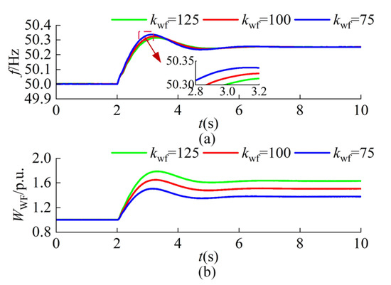
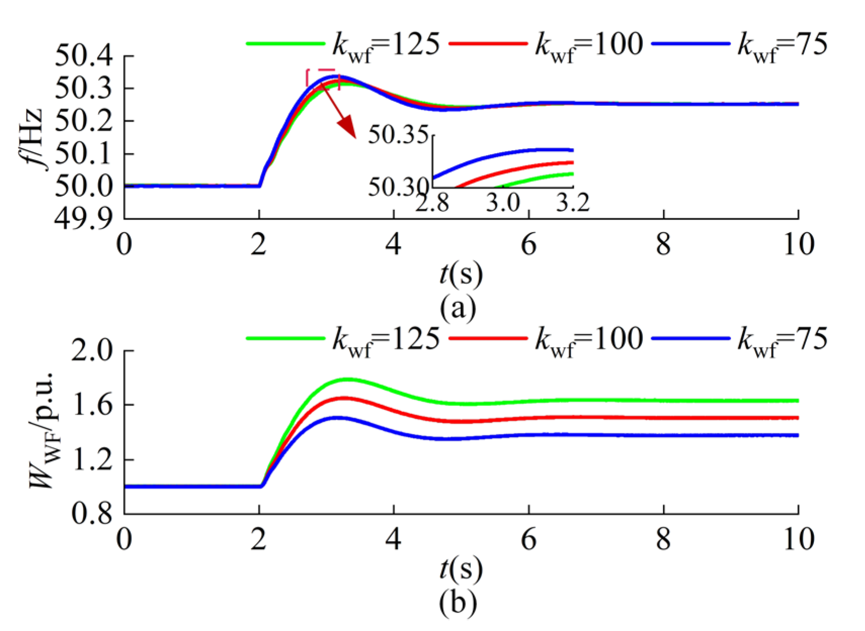
Figure 5 presents the system’s dynamic response to different kwf. The results clearly show that an increase in kwf enables WFMMC to absorb greater amounts of energy, which in turn reduces the maximum frequency deviation. This confirms the expected enhancement in inertia support.
Figure 5.
Dynamic characteristics under varying droop coefficient. (a) Grid frequency. (b)WFMMC capacitor energy.
5.1.3. Inertia Support of OWF
Due to the voltage deviation limits of the submodule capacitors, the inertia support provided by the capacitor energy in the MMC-HVDC is limited. To maximize wind energy utilization, the wind turbines within the OWF operate in Maximum Power Point Tracking mode under normal conditions, eliminating the need for wind curtailment to maintain a continuous active power reserve. In the event of large disturbances in the onshore AC grid, the rotor kinetic energy of the offshore wind turbines can be further leveraged to enhance the inertia support capability.
Since there are virtually no commercial or residential loads offshore, the offshore AC grid can be controlled to operate at a variable-frequency. By establishing a coupling between the offshore and onshore grid frequencies, variations in the onshore grid frequency are reflected in the AC frequency of the OWF. Combining this approach with (29), the reference value for the offshore grid frequency is expressed as:
To mitigate frequency variations in the onshore AC grid, the OWF employs inertia control to emulate the inertial response of synchronous generators. Accordingly, the support power provided by the wind turbines is expressed as:
where kwt is the OWF inertia control coefficient. Consequently, the active power reference for the OWF is formulated as:
where Pwt0 denotes the steady-state active power reference of the OWF.
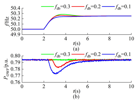
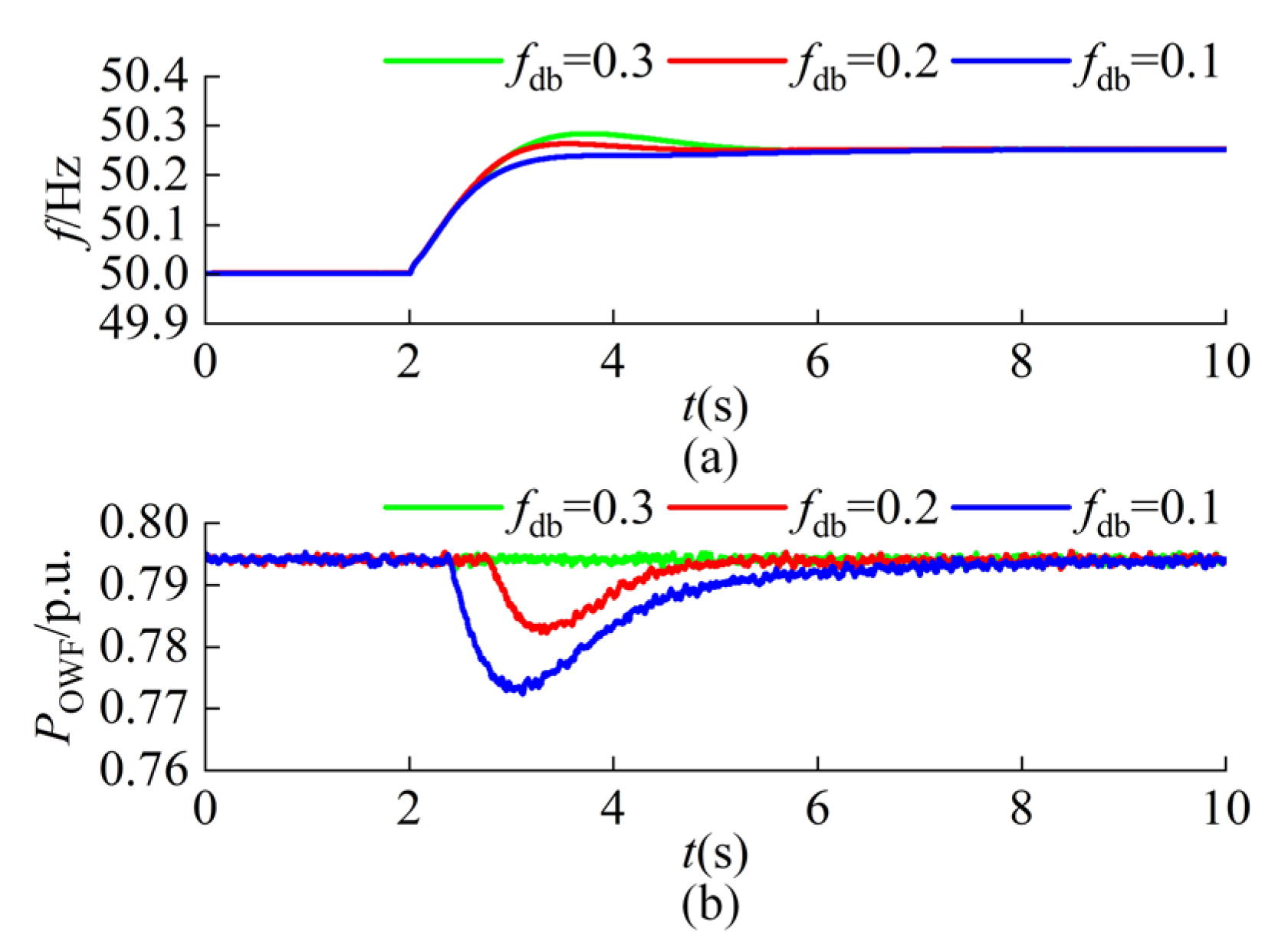
Figure 6 illustrates the dynamic responses of the system under varying frequency deadbands. As observed, the deadband threshold determines both the activation time and the participation level of the OWF. Specifically, a narrower deadband advances the initiation of inertia support and increases the magnitude of the provided support power. Conversely, an excessively wide deadband may completely preclude the OWF from participating. Therefore, the frequency deadband must be carefully optimized to strike a balance between disturbance isolation and effective system support.
Figure 6.
Dynamic characteristics under varying frequency deadband. (a) Grid frequency. (b) OWF output power.
5.2. Coordinated Inertia Support Strategy of Multiple Entities
In the offshore wind power-integrated MMC-HVDC system, GSMMC, WFMMC, and OWF each possess inertia support capabilities. Therefore, to enhance the frequency stability of the system, a coordinated inertia support strategy is proposed.
5.2.1. Coordinated Inertia Support Between WFMMC and GSMMC
The converters possess inherent capacitor energy margins. To facilitate rapid active inertia support, both GSMMC and WFMMC must participate synergistically in system inertia regulation.
As discussed in Section 5.1.2, the DC voltage serves as the medium for transmitting the frequency signals of the onshore AC grid under the decoupling control. Consequently, by implementing ω-Wc droop control in GSMMC and Udc-Wc droop control in WFMMC, communication-free coordinated control between the OWF and onshore AC grid is realized. In contrast to the inertia support strategy of an individual entity, the coordinated strategy ensures the maximal utilization of capacitor energy storage within the MMC-HVDC, thereby effectively mitigating the rate of change in frequency during the initial stages of a disturbance.
5.2.2. Coordinated Inertia Support Between MMC-HVDC System and OWF
The demand for system inertia support varies significantly depending on the specific characteristics of power disturbance scenarios. While the MMC-HVDC system offers advantages such as control flexibility and rapid regulation, its inertia support capability is constrained by the limited energy margins of the submodule capacitors. Therefore, to further enhance system frequency stability, it is essential to implement a coordinated inertia support strategy involving both the MMC-HVDC system and the OWF.
To maintain system frequency stability while mitigating the propagation of disturbances, a coordinated inertia support strategy is proposed. By incorporating a frequency deadband, the impact of minor onshore AC grid disturbances on the OWF is minimized. This approach simultaneously enhances the frequency stability of the onshore grid and achieves optimal utilization of inertia support energy within the entire system. Accordingly, the inertia support power provided by the OWF is expressed as:
where fdb denotes the frequency deadband, and Δf represents the frequency deviation of the onshore AC grid. Clearly, the value of the frequency deadband directly determines the extent of the OWF’s participation in providing inertia support to the onshore AC grid. Specifically, if the frequency deviation remains within the designated deadband, the OWF maintains its pre-disturbance operating state; consequently, inertia support is provided exclusively by the capacitor energy of the MMC-HVDC system. Conversely, if the frequency deviation exceeds the deadband, the OWF dynamically regulates its power output in response to the frequency change, operating synergistically with the MMC-HVDC capacitor energy to enhance the system’s overall inertia support capability. In accordance with the Chinese National Standard GB/T 15945-2008, Power Quality-Deviation of Power System Frequency, the permissible frequency deviation under normal operating conditions is specified as ±0.2 Hz [27]. Therefore, the frequency deadband in the proposed strategy is set to ±0.2 Hz to prevent the offshore wind farm from reacting to minor frequency fluctuations.
6. Case Study
To validate the effectiveness of the proposed control strategy, a ±320 kV offshore wind power-integrated MMC-HVDC system is modeled in PSCAD/EMTDC 4.6.2 using the efficient simulation model [28]. The MMC-HVDC system adopts a pseudo bipolar connection with a rated capacity of 1000 MW. The detailed parameters of the MMC-HVDC system and the detailed controller parameters are listed in Table 1 and Table 2.
Table 2.
Detailed controller parameters of the MMC-HVDC system.
6.1. Capacitor Energy-Based Grid-Forming Control Strategy
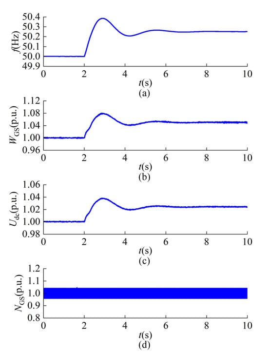
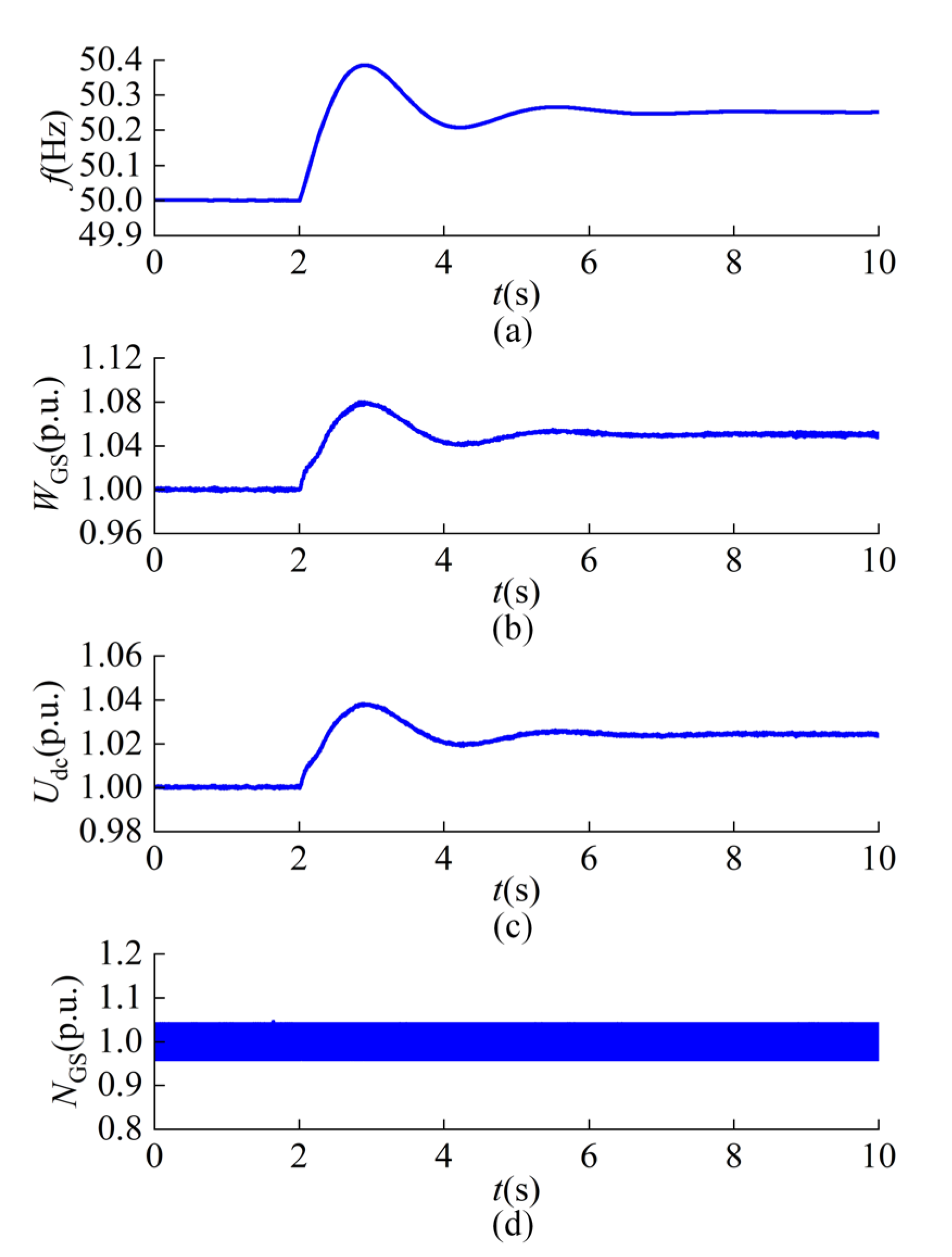
At t = 2 s, a sudden load reduction of 100 MW occurs in the onshore AC grid. The dynamic responses of the grid frequency, GSMMC capacitor energy, DC voltage, and the number of inserted submodules per phase unit are shown in Figure 7.
Figure 7.
Dynamic characteristics of GSMMC when the load decreases. (a) Grid frequency. (b) GSMMC capacitor energy. (c) DC voltage. (d) The number of inserted submodules per phase unit.
In response to the frequency deviation, GSMMC mitigates the power imbalance by exchanging energy via its internal capacitors. Simultaneously, GSMMC output frequency is dynamically adjusted through capacitor energy regulation, enabling fast frequency tracking and self-synchronous operation. Furthermore, since the number of inserted submodules in each phase remains constant, the DC voltage is proportional to the average submodule capacitor voltage. Consequently, the DC voltage varies synchronously with the grid frequency.
6.2. Decoupled Control Strategy
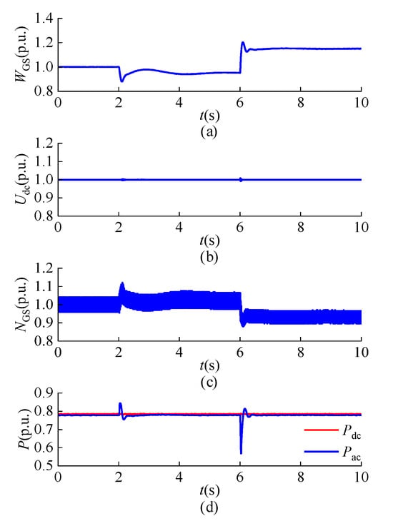
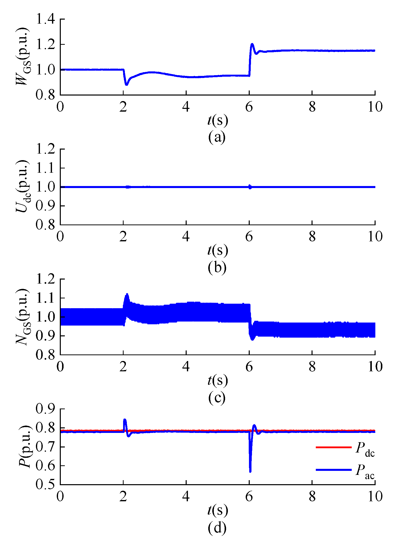
First, the capacitor energy regulation capability of GSMMC is verified. At t = 2 s and t = 6 s, the reference value for GSMMC submodule capacitor energy is adjusted to 0.9 and 1.1, respectively. The dynamic responses of GSMMC capacitor energy, DC voltage, the number of inserted submodules per phase unit, and the AC/DC power are presented in Figure 8.
Figure 8.
Dynamic characteristics of GSMMC under decoupled control. (a) Capacitor energy. (b) DC voltage. (c) The number of inserted submodules per phase unit. (d) AC/DC power.
It is observed that the submodule capacitor energy of GSMMC accurately tracks the reference value. When the capacitor energy decreases, the AC power of GSMMC increases, temporarily exceeding the DC power. Conversely, when the capacitor energy increases, AC power decreases, dropping below DC power. Through this mechanism, dynamic energy balance within the system is maintained. Notably, during the regulation process, DC voltage remains stable at 1.0 p.u., unaffected by variations in the submodule capacitor energy. This stability is attributed to the DC voltage control strategy, which decouples the capacitor energy from the DC voltage by dynamically adjusting the number of inserted submodules per phase. Specifically, as the submodule capacitor energy decreases, causing a drop in the average capacitor voltage, GSMMC increases the number of inserted submodules per phase to maintain the DC voltage constant. Conversely, when the capacitor energy increases and the average capacitor voltage rises, the number of inserted submodules is reduced accordingly.
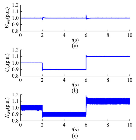
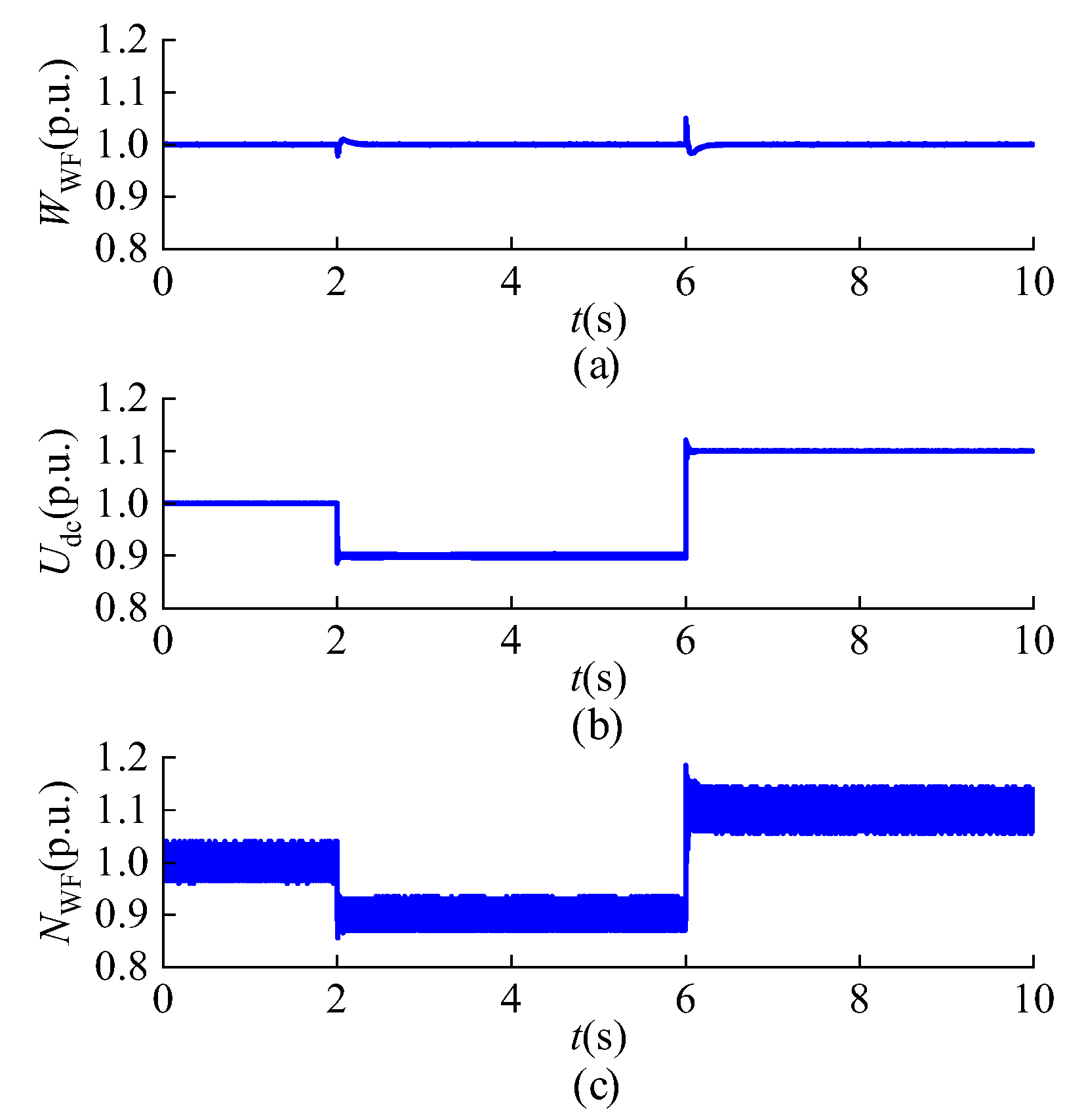
Next, the capacitor energy regulation capability of WFMMC is examined. At t = 2 s and t = 6 s, the DC voltage reference is adjusted to 0.9 and 1.1, respectively. The dynamic responses of the capacitor energy, DC voltage, and the number of inserted submodules per phase unit of the WFMMC are presented in Figure 9.
Figure 9.
Dynamic characteristics of WFMMC under decoupled control. (a) Capacitor energy. (b) DC voltage. (c) The number of inserted submodules per phase unit.
It is observed that the DC voltage accurately tracks its reference value. Throughout the DC voltage regulation process, the submodule capacitor energy of WFMMC remains constant at 1.0 p.u. Under the decoupled control strategy, a decrease in DC voltage leads to a reduction in the number of inserted submodules per phase, whereas an increase in DC voltage results in a corresponding increase in the number of inserted submodules. These results demonstrate that the capacitor energy control strategy adopted by WFMMC effectively decouples the capacitor energy from the DC voltage by regulating the number of inserted submodules per phase.
6.3. Inertia Support Strategies
To verify the inertia support capability of the offshore wind integrated MMC-HVDC system, the dynamic responses under the following six control strategies are compared:
Case 1: GSMMC adopts the decoupled capacitor energy-based grid-forming control strategy.
Case 2: Inertia support is provided exclusively by GSMMC.
Case 3: Inertia support is provided exclusively by WFMMC.
Case 4: Inertia support is provided exclusively by the OWF.
Case 5: Coordinated inertia support between WFMMC and GSMMC.
Case 6: Coordinated Inertia Support Between MMC-HVDC System and OWF
6.3.1. Inertia Support of Individual Entity
To evaluate the inertia support capability of an individual entity, a sudden load reduction of 10% is applied to the onshore AC grid at t = 2 s. The dynamic responses of the system under different control strategies are compared in Figure 10, including the grid frequency, DC voltage, capacitor energies of the GSMMC and WFMMC, the number of inserted submodules per phase in both converters, and the OWF output power.
Figure 10.
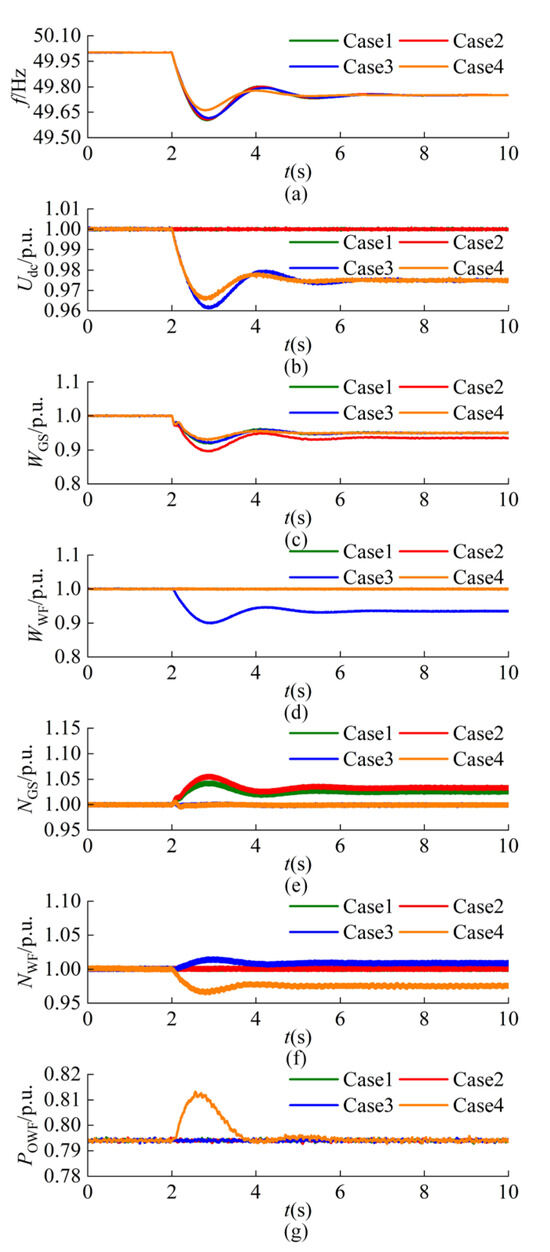
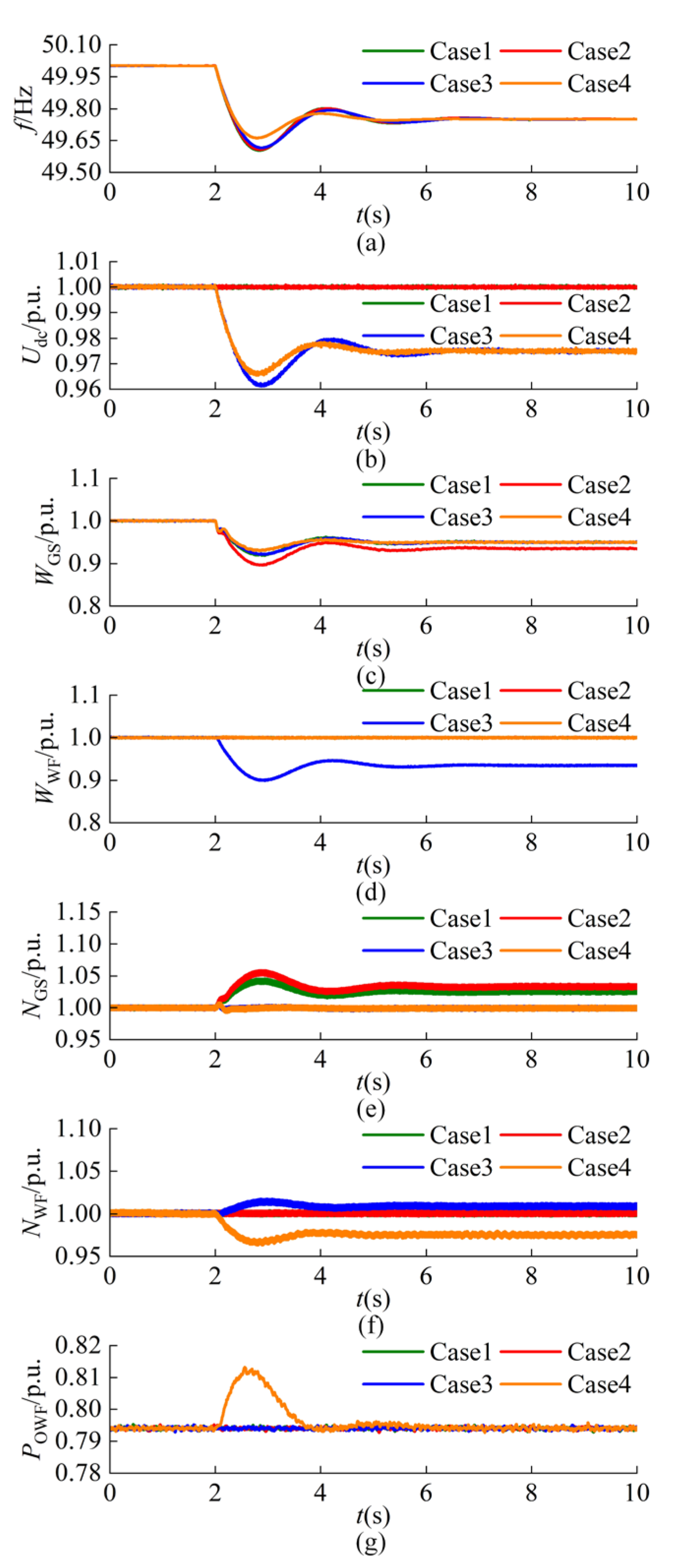
Dynamic characteristics of the system with single-entity support under a sudden 10% load reduction. (a) Grid frequency. (b) DC voltage. (c) GSMMC capacitor energy. (d) WFMMC capacitor energy. (e) The number of inserted submodules per phase unit in GSMMC. (f) The number of inserted submodules per phase unit in WFMMC. (g) OWF output power.
As shown in Figure 10a, the introduction of inertia support strategies significantly reduces the peak grid frequency, indicating that GSMMC, WFMMC, and the OWF are all capable of providing effective inertia support. When GSMMC operates solely with the decoupled capacitor energy-based grid-forming control (Case 1), the maximum grid frequency reaches 50.39 Hz. When inertia support is provided solely by either GSMMC or WFMMC, the peak frequency decreases further to 50.32 Hz, demonstrating that converters offer comparable inertia support capabilities. Furthermore, with inertia support provided exclusively by the OWF, the frequency peak is reduced to 50.34 Hz.
Moreover, when inertia support is provided exclusively by GSMMC, the DC voltage of the MMC-HVDC system remains constant due to the decoupled control. However, to leverage the capacitor energy of WFMMC and the kinetic energy of the OWF, the onshore grid frequency signal must be transmitted via the DC voltage. Consequently, when either WFMMC or OWF provides inertia support, the DC voltage varies synchronously with the onshore grid frequency. Notably, the number of inserted submodules per phase is reduced when inertia support strategies are applied in both GSMMC and WFMMC, thereby enabling maximal utilization of the available capacitor energy.
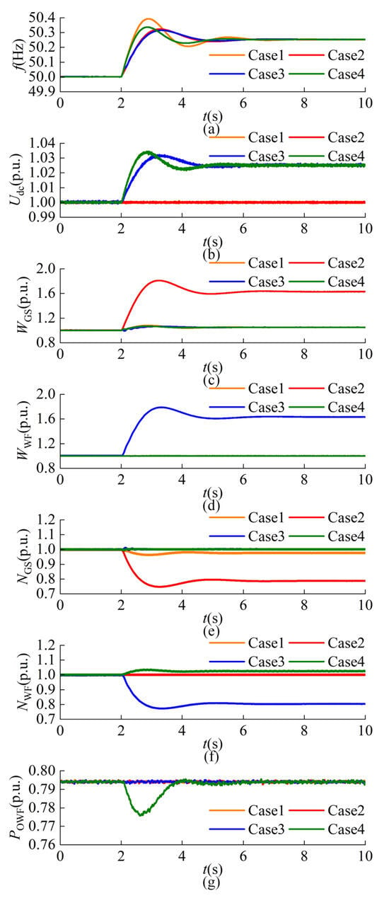
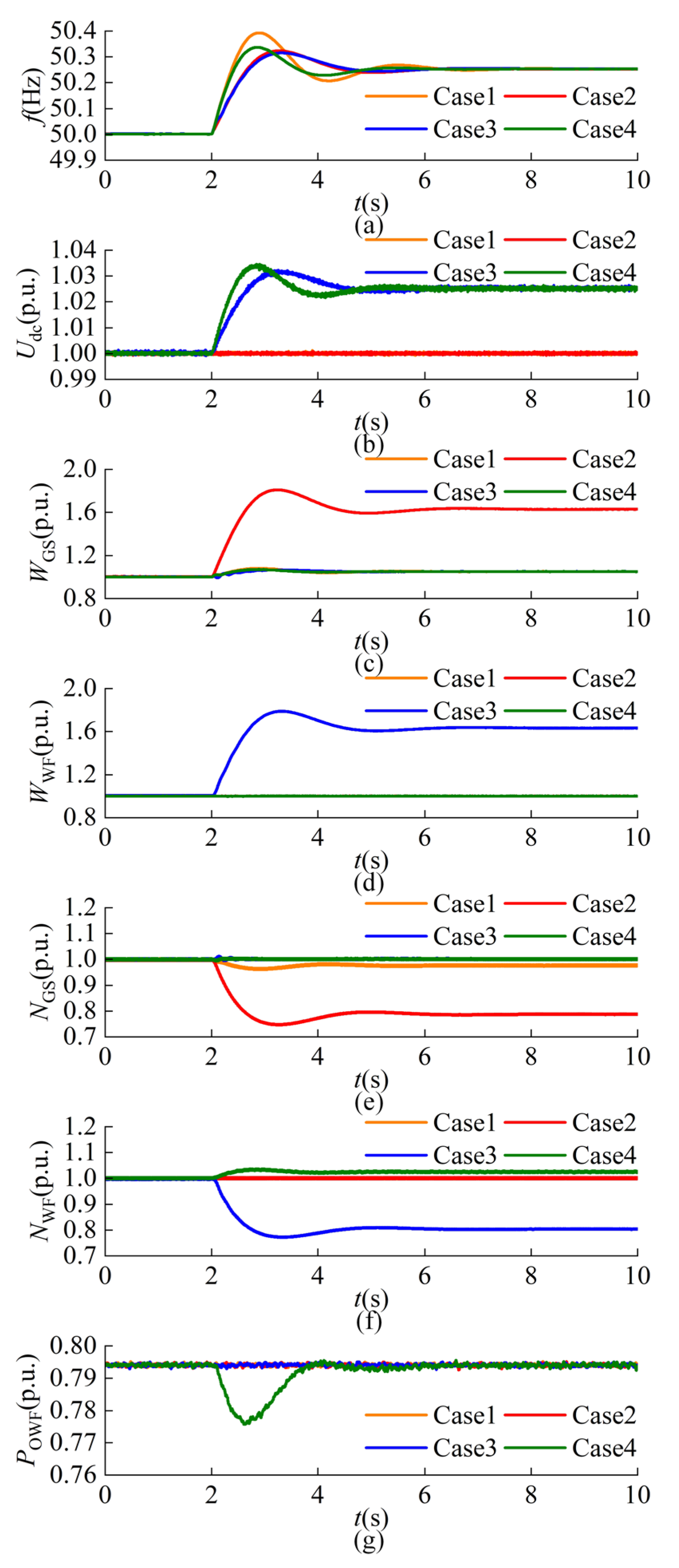
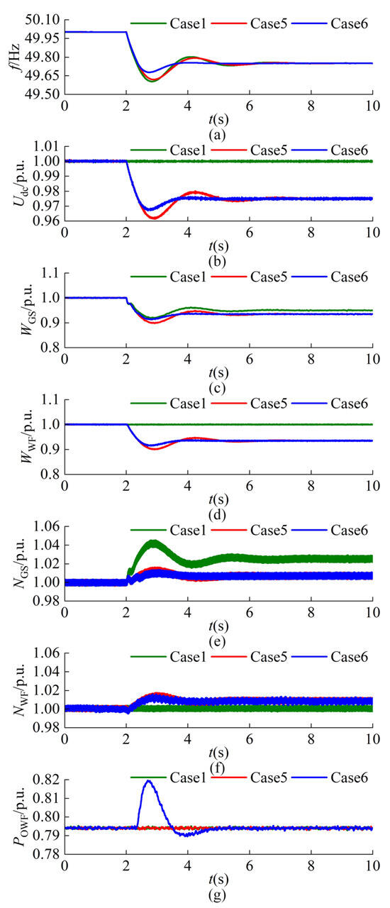
A sudden 10% load increase is applied to the onshore AC grid at t = 2 s. Figure 11 presents the corresponding dynamic responses under different control strategies, including the grid frequency, DC voltage, capacitor energies of the GSMMC and WFMMC, the number of inserted submodules per phase in both converters, and the OWF output power.
Figure 11.
Dynamic characteristics of the system with single-entity support under a sudden 10% load increase. (a) Grid frequency. (b) DC voltage. (c) GSMMC capacitor energy. (d) WFMMC capacitor energy. (e) The number of inserted submodules per phase unit in GSMMC. (f) The number of inserted submodules per phase unit in WFMMC. (g) OWF output power.
As shown in Figure 11a, when GSMMC operates solely with the decoupled capacitor energy-based grid-forming control (Case 1), the minimum frequency of the onshore grid drops to 49.60 Hz. After introducing inertia support from GSMMC or WFMMC, the frequency nadir increases to 49.61 Hz. When inertia support is provided solely by the OWF, the nadir further rises to 49.66 Hz. These results show that both GSMMC and WFMMC can effectively mitigate the frequency drop. The mitigation effect depends on the available margin for capacitor energy release. Because the number of submodules in each arm is limited, the energy release margin is smaller than the absorption margin. Therefore, under a sudden load increase, the frequency support capability provided by the capacitor energy is reduced. Furthermore, due to the existence of decoupled control, DC voltage is also used to transmit frequency disturbance signals. It should be noted that, in Cases 3 and 4, the DC voltage and the submodule capacitor voltage of GSMMC decrease synchronously. As a result, the number of inserted submodules per phase in GSMMC remains unchanged. However, in Case 4, the DC voltage decreases as the onshore grid frequency declines. To maintain voltage matching, WFMMC must reduce the number of inserted submodules.
6.3.2. Coordinated Inertia Support of Multiple Entities
To verify the coordinated inertia support capability of multiple entities, a sudden load reduction of 10% is applied to the onshore AC grid at t = 2 s. The dynamic responses of the system under different control strategies are compared in Figure 12, including the grid frequency, DC voltage, capacitor energies of the GSMMC and WFMMC, the number of inserted submodules per phase in both converters, and the OWF output power.
Figure 12.
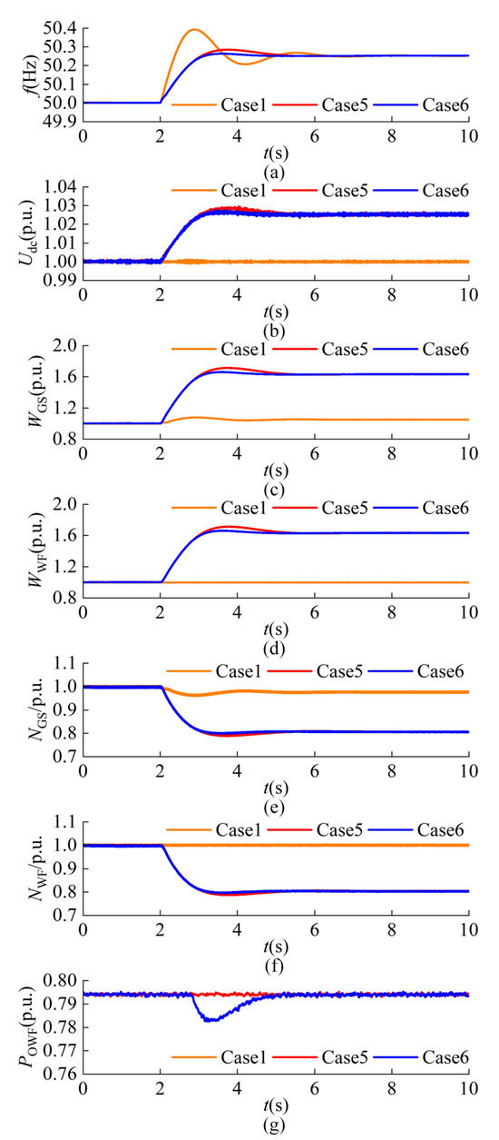
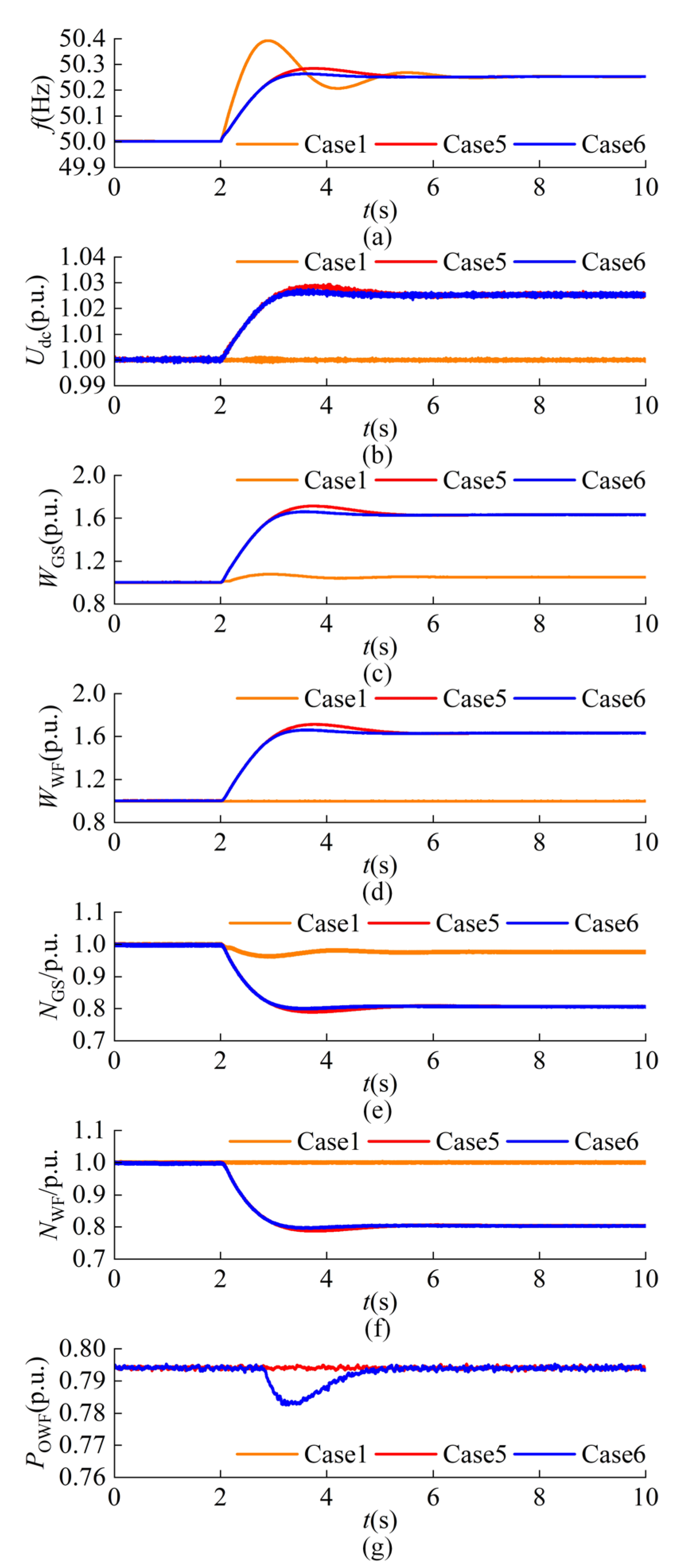
Dynamic characteristics of the system with multi-entity support under a sudden 10% load reduction. (a) Grid frequency. (b) DC voltage. (c) GSMMC capacitor energy. (d) WFMMC capacitor energy. (e) The number of inserted submodules per phase unit in GSMMC. (f) The number of inserted submodules per phase unit in WFMMC. (g) OWF output power.
When multiple entities participate in coordinated inertia support, the transient frequency response of the onshore power grid is substantially improved. Specifically, by integrating the coordinated inertia support of GSMMC and WFMMC, the frequency deadband control of the OWF is incorporated to enable inertia support. Consequently, the peak grid frequency is reduced from 50.28 Hz to 50.26 Hz. Compared with Case 1, the maximum frequency deviation is reduced by 33.3%. The results indicate that the proposed coordinated inertia support strategy effectively suppresses the frequency peak of the onshore AC grid. Furthermore, the suppression effect is positively correlated with the available inertia support energy. In addition, as shown in Figure 12g, the OWF begins to provide inertia support power at t = 2.9 s. This delayed response confirms the effectiveness of the frequency deadband mechanism. The results demonstrate that the MMC-HVDC system and the OWF achieve effective coordination across multiple time scales. This coordination enhances system frequency stability under large disturbances while simultaneously mitigating the impact of small disturbances on the operation of the OWF.
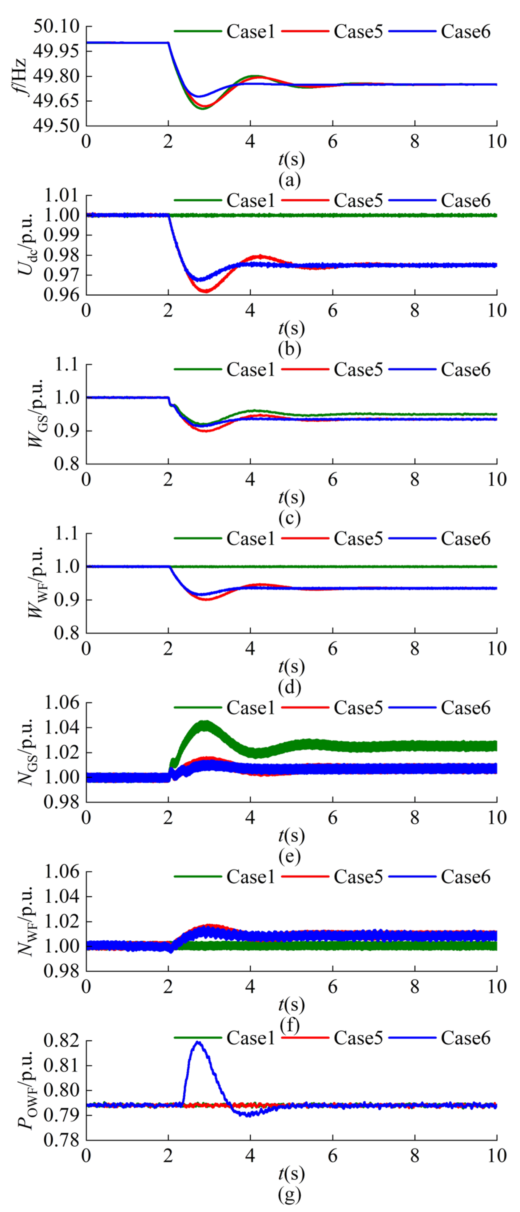
A sudden 10% load increase is applied to the onshore AC grid at t = 2 s. Figure 13 compares the corresponding dynamic responses under different coordinated control strategies, including the grid frequency, DC voltage, capacitor energies of the GSMMC and WFMMC, the number of inserted submodules per phase in both converters, and the OWF output power. As shown in Figure 13a, the proposed coordinated inertia support strategy effectively improves the frequency nadir of the onshore AC grid. Compared to Case 1, the maximum frequency deviation is reduced by 18.7%, demonstrating a significant enhancement in system frequency stability. Furthermore, as depicted in Figure 13g, the OWF begins to provide inertia support power at t = 2.3 s. Governed by the frequency deadband, the OWF is effectively prevented from reacting to minor frequency fluctuations. Overall, these results verify the effectiveness of the proposed coordinated inertia support strategy.
Figure 13.
Dynamic characteristics of the system with multi-entity support under a sudden 10% load increase. (a) Grid frequency. (b) DC voltage. (c) GSMMC capacitor energy. (d) WFMMC capacitor energy. (e) The number of inserted submodules per phase unit in GSMMC. (f) The number of inserted submodules per phase unit in WFMMC. (g) OWF output power.
7. Discussion
To fully evaluate the engineering feasibility of the proposed coordinated inertia support strategy, its practical implementation is analyzed with respect to control complexity, switching stress, thermal loading, and the long-term reliability of the power electronic devices.
Firstly, an analysis of the control complexity is provided. By introducing DC voltage control at GSMMC and capacitor energy control at WFMMC, the submodule capacitor voltage and DC voltage are decoupled. The decoupled mechanism dynamically adjusts the inserted submodules by regulating the DC modulation ratio via PI controllers. This approach integrates seamlessly with existing control architectures without imposing excessive computational burdens on modern digital controllers.
Secondly, the implications of switching stress and thermal loading are analyzed. Under the proposed decoupled control, the number of inserted submodules per phase dynamically decreases when the system frequency rises, and increases when the frequency drops. While this dynamic adjustment alters the switching actions, the inherent submodule capacitor voltage balancing algorithm ensures that these additional or reduced switching actions are evenly distributed among all submodules. Consequently, this uniform distribution effectively prevents any specific IGBT from enduring excessively high thermal stress, thereby safeguarding the long-term reliability of the power electronic devices.
Finally, the long-term reliability of power electronic devices is discussed. As detailed in our analysis of transient support capabilities, capacitors can withstand 1.61 times of nominal operating voltage for a continuous duration of 30 min. Because grid inertia support is a short-term transient event and the capacitor energy variation is strictly confined within permissible hardware limits, the temporary operational stress has a negligible impact on semiconductor lifetime and overall capacitor aging.
8. Conclusions
This paper proposes a coordinated inertia support strategy for offshore wind power-integrated MMC-HVDC systems. The feasibility and effectiveness of the strategy are validated in PSCAD/EMTDC 4.6.2.
The results demonstrate that the decoupled capacitor energy-based grid-forming control effectively separates submodule capacitor energy from DC voltage by adaptively regulating the number of inserted submodules. This method significantly enhances the converter’s transient support capability. Building on this, DC voltage is utilized to transmit onshore frequency signals, enabling a coordinated inertia support strategy. Specifically, capacitors prioritize responses to small disturbances, while the OWF participates cooperatively during large disturbances. Simulation results under sudden load reduction show that the proposed strategy reduces the maximum frequency deviation of the onshore AC grid by 33.3%, significantly outperforming single-entity inertia support schemes. Furthermore, the strategy mitigates the impact of small disturbances on the OWF while ensuring system frequency stability, thereby achieving an overall improvement in dynamic performance.
Despite the effectiveness of the proposed strategy, certain limitations remain. The simulation results indicate that the capacitor energy release margin is significantly smaller than the absorption margin. This asymmetry arises because the minimum allowable capacitor voltage is constrained by the maximum modulation index, which restricts the depth of energy release. To further enlarge the available release margin, potential solutions such as third-harmonic injection and the utilization of redundant submodules warrant consideration in future research. Moreover, the present study is limited to a point-to-point MMC-HVDC transmission system. Future work will focus on extending the proposed coordinated strategy to multi-terminal DC systems, thereby enabling its application in more complex offshore wind power integration scenarios and improving overall system flexibility and resilience.
Author Contributions
Conceptualization, C.T. and Y.L.; methodology, H.L.; software, R.L.; validation, Y.L., H.L. and R.L.; formal analysis, C.T.; investigation, Z.L.; resources, X.P.; data curation, C.T.; writing—original draft preparation, Q.Y.; writing—review and editing, H.X.; visualization, Y.L.; supervision, H.X.; project administration, C.T.; funding acquisition, C.T. All authors have read and agreed to the published version of the manuscript.
Funding
This research received no external funding.
Data Availability Statement
The original contributions presented in this study are included in the article. Further inquiries can be directed to the corresponding author.
Acknowledgments
We would like to express our sincere gratitude to HVDC Transmission and Protection control technology team for the financial support and technical support.
Conflicts of Interest
The authors declare no conflicts of interest.
References
- Xiao, H.; Gan, H.; Huang, Y.; Zhang, L.; Yang, P. Review on Emerging Collection and Transmission Technologies for Large-Scale Offshore Wind Power. J. Mod. Power Syst. Clean Energy 2025, 1–17. [Google Scholar] [CrossRef] [Scilit]
- Shu, Y.B.; Tang, Y.; Zhang, Z.L.; Zhang, F.Y.; Zhong, W.Z.; Shi, H.B.; Yang, L.; Kong, M.; Gu, Z.Y.; Yu, Y.D. Pathway for New-type Power System in China. CSEE J. Power Energy Syst. 2025, 11, 2684–2695. [Google Scholar] [CrossRef] [Scilit]
- Yin, L.C.; Liu, Y.Q.; Wu, Y.C.; Li, Z.J.; Zhou, F.; Liu, J.Y.; Zheng, G. A Novel MMC Topology Integrated DC Fault Current Blocking and Energy Dissipation Equipment for Offshore Wind VSC-HVDC System. IEEE Trans. Ind. Appl. 2026, 62, 1607–1617. [Google Scholar] [CrossRef] [Scilit]
- Pan, R.C.; Yang, Y.X.; Yang, J.; Liu, D. Enhanced grid forming control for MMC-HVDC with DC power and voltage regulation. Electr. Power Syst. Res. 2024, 229, 110166. [Google Scholar] [CrossRef] [Scilit]
- Huang, Y.; Zhang, J.; Wang, G.; Xu, Z. Transient stability analysis and improvement of isolated renewable energy bases with VSC-DC transmission. CSEE J. Power Energy Syst. 2025, 1–11. [Google Scholar] [CrossRef] [Scilit]
- Shafiullah, M.; Ahmed, S.D.; Al-Sulaiman, F.A. Grid Integration Challenges and Solution Strategies for Solar PV Systems: A Review. IEEE Access 2022, 10, 52233–52257. [Google Scholar] [CrossRef] [Scilit]
- Zhang, L.D.; Harnefors, L.; Nee, H.P. Power-Synchronization Control of Grid-Connected Voltage-Source Converters. IEEE Trans. Power Syst. 2010, 25, 809–820. [Google Scholar] [CrossRef] [Scilit]
- Xiao, H.Q.; He, H.L.; Zhang, L.D.; Liu, T. Adaptive Grid-Synchronization Based Grid-Forming Control for Voltage Source Converters. IEEE Trans. Power Syst. 2024, 39, 4763–4766. [Google Scholar] [CrossRef] [Scilit]
- Ye, Y.D.; Qiao, Y.; Xie, L.; Lu, Z.X. A Comprehensive Power Flow Approach for Multi-terminal VSC-HVDC System Considering Cross-regional Primary Frequency Responses. J. Mod. Power Syst. Clean Energy 2020, 8, 238–248. [Google Scholar] [CrossRef] [Scilit]
- Xiao, H.Q.; Yang, Q.L.; Zhu, Q.H.; Zhang, L.D. Grid-Supporting HVDC System With Low-Voltage Energy Storage for Renewables Integration. IEEE Trans. Power Deliv. 2025, 40, 3178–3190. [Google Scholar] [CrossRef] [Scilit]
- Miao, Z.X.; Fan, L.L.; Osborn, D.; Yuvarajan, S. Wind Farms With HVdc Delivery in Inertial Response and Primary Frequency Control. IEEE Trans. Energy Convers. 2010, 25, 1171–1178. [Google Scholar] [CrossRef] [Scilit]
- Liu, H.Z.; Chen, Z. Contribution of VSC-HVDC to Frequency Regulation of Power Systems With Offshore Wind Generation. IEEE Trans. Energy Convers. 2015, 30, 918–926. [Google Scholar] [CrossRef] [Scilit]
- Sanz, I.M.; Chaudhuri, B.; Strbac, G. Inertial Response From Offshore Wind Farms Connected Through DC Grids. IEEE Trans. Power Syst. 2015, 30, 1518–1527. [Google Scholar] [CrossRef] [Scilit]
- Phulpin, Y. Communication-Free Inertia and Frequency Control for Wind Generators Connected by an HVDC-Link. IEEE Trans. Power Syst. 2012, 27, 1136–1137. [Google Scholar] [CrossRef] [Scilit]
- Kou, P.; Liang, D.L.; Wu, Z.H.; Ze, Q.J.; Gao, L. Frequency Support From a DC-Grid Offshore Wind Farm Connected Through an HVDC Link: A Communication-Free Approach. IEEE Trans. Energy Convers. 2018, 33, 1297–1310. [Google Scholar] [CrossRef] [Scilit]
- Xiong, Y.X.; Yao, W.; Wen, J.F.; Lin, S.Q.; Ai, X.M.; Fang, J.K.; Wen, J.Y.; Cheng, S.J. Two-Level Combined Control Scheme of VSC-MTDC Integrated Offshore Wind Farms for Onshore System Frequency Support. IEEE Trans. Power Syst. 2021, 36, 781–792. [Google Scholar] [CrossRef] [Scilit]
- Huang, L.B.; Xin, H.H.; Wang, Z.; Wu, K.Y.; Wang, H.J.; Hu, J.B.; Lu, C.C. A Virtual Synchronous Control for Voltage-Source Converters Utilizing Dynamics of DC-Link Capacitor to Realize Self-Synchronization. IEEE J. Emerg. Sel. Topics Power Electron. 2017, 5, 1565–1577. [Google Scholar] [CrossRef] [Scilit]
- Arghir, C.; Jouini, T.; Dörfler, F. Grid-forming control for power converters based on matching of synchronous machines. Automatica 2018, 95, 273–282. [Google Scholar] [CrossRef] [Scilit]
- Zhu, J.B.; Booth, C.D.; Adam, G.P.; Roscoe, A.J.; Bright, C.G. Inertia Emulation Control Strategy for VSC-HVDC Transmission Systems. IEEE Trans. Power Syst. 2013, 28, 1277–1287. [Google Scholar] [CrossRef] [Scilit]
- Zhu, J.B.; Shen, Z.P.; Bu, S.Q.; Li, X.L.; Booth, C.D.; Qiu, W.; Jia, H.J.; Wang, C.S. Coordinated Flexible Damping Mechanism With Inertia Emulation Capability for MMC-MTDC Transmission Systems. IEEE J. Emerg. Sel. Topics Power Electron. 2021, 9, 7329–7342. [Google Scholar] [CrossRef] [Scilit]
- Zhu, J.B.; Wang, X.N.; Zhao, J.B.; Yu, L.J.; Li, S.X.; Li, Y.W.; Guerrero, J.M.; Wang, C.S. Inertia Emulation and Fast Frequency-Droop Control Strategy of a Point-to-Point VSC-HVdc Transmission System for Asynchronous Grid Interconnection. IEEE Trans. Power Electron. 2022, 37, 6530–6543. [Google Scholar] [CrossRef] [Scilit]
- Jiang, S.Q.; Wang, H.B.; Li, G.Q.; Xin, Y.C.; Wang, L.X.; Xu, Y.A. A Novel Coordinated Control Strategy for Frequency Regulation of MMC-HVDC Connecting Offshore Wind Farms. IEEE Trans. Sustain. Energy 2024, 15, 1028–1038. [Google Scholar] [CrossRef] [Scilit]
- Yang, R.X.; Shi, G.; Zhang, C.; Li, G.; Cai, X. Internal Energy Based Grid-Forming Control for MMC-HVDC Systems With Wind Farm Integration. IEEE Trans. Ind. Appl. 2023, 59, 503–512. [Google Scholar] [CrossRef] [Scilit]
- Zhang, H.B.; Xiang, W.; He, Y.J.; Wen, J.Y. Optimal Energy Utilization of MMC-HVDC System Integrating Offshore Wind Farms for Onshore Weak Grid Inertia Support. IEEE Trans. Power Syst. 2024, 39, 1304–1318. [Google Scholar] [CrossRef] [Scilit]
- Zhang, H.B.; Xiang, W.; Wen, J.Y. Dual Grid-Forming Control With Energy Regulation Capability of MMC-HVDC System Integrating Offshore Wind Farms and Weak Grids. IEEE Trans. Power Syst. 2024, 39, 261–272. [Google Scholar] [CrossRef] [Scilit]
- Liu, Z.W.; Lv, X.J.; Wu, F.; Li, Z.X. Multi-Mode Active Inertia Support Strategy for MMC-HVDC Systems Considering the Constraint of DC Voltage Fluctuations. IEEE Trans. Power Deliv. 2023, 38, 2767–2781. [Google Scholar] [CrossRef] [Scilit]
- GB/T 15945-2008; Power Quality—Frequency Deviation For Power System. National Standardization Administration: Beijing, China, 2008.
- Zhu, Q.; Xiao, H.; Yang, Q.; Yang, P.; Dong, Y.; Zhang, L. General and Efficient Simulation Model for Energy Storage-Embedded MMC With Adaptability to Multiple Submodule Topologies. IEEE Trans. Ind. Appl. 2026, 62, 37–48. [Google Scholar] [CrossRef] [Scilit]

Disclaimer/Publisher’s Note: The statements, opinions and data contained in all publications are solely those of the individual author(s) and contributor(s) and not of MDPI and/or the editor(s). MDPI and/or the editor(s) disclaim responsibility for any injury to people or property resulting from any ideas, methods, instructions or products referred to in the content. |
© 2026 by the authors. Licensee MDPI, Basel, Switzerland. This article is an open access article distributed under the terms and conditions of the Creative Commons Attribution (CC BY) license.