


Abstract
The rapid proliferation of small satellite missions demands flight software that combines reliability, reusability, and rapid development cycles. NASA’s Core Flight System (cFS), with its layered architecture and component-based design, offers a promising solution. However, its resource-intensive design poses significant challenges for deployment on microcontroller (MCU) platforms commonly used in nanosatellites. This paper presents a comprehensive approach to porting cFS to the TMS570 safety microcontroller running FreeRTOS. We address critical challenges including Operating System Abstraction Layer (OSAL) adaptation for lightweight real-time operating systems and file system virtualization using RAM disk. As a core architectural contribution, we propose a hierarchical memory architecture that partitions high-speed internal RAM from external SDRAM, enabling all five cFE core services to operate within 256 KB on-chip RAM by offloading latency-tolerant data structures to SDRAM and releasing 37.5% of internal memory for mission applications. Performance evaluation yields two key quantitative findings: (1) Software Bus latency on SDRAM scales non-linearly from 1.85× to 7.67× relative to internal RAM as message size increases from 64 B to 4 KB, revealing that memory bandwidth—not fixed routing overhead—dominates large-transfer cost; (2) the cFS framework introduces a constant additive overhead of approximately 82.5 s per task cycle, independent of computational load, remaining below 0.1% of the execution budget at typical 1–10 Hz control rates. System stability is validated through 72 h continuous operation encompassing over 2.5 million task cycles with zero unplanned resets. This work establishes quantitative design guidelines—including memory placement criteria and task granularity thresholds—that provide a reusable technical pathway for deploying reliable, extensible flight software on resource-constrained embedded platforms.
1. Introduction
With the advent of the “New Space” era, nanosatellites have evolved from early educational and verification platforms to operational systems undertaking complex missions including scientific exploration, Earth observation, and communication relay [1,2]. The exponential growth in mission complexity poses severe challenges to the reliability, reusability, and development cycle of onboard flight software [3,4]. Recent surveys on embedded software architectures [5] have highlighted the critical importance of modular design and sensor fusion techniques for resource-constrained platforms. Traditional development approaches, which produce tightly coupled monolithic software for specific hardware platforms, can no longer meet the demands of rapid mission iteration, resulting in low software reuse rates and high maintenance costs.
Against this backdrop, the Core Flight System (cFS) developed by NASA’s Goddard Space Flight Center (GSFC) has emerged as a powerful solution, offering layered architecture, component-based design, and platform independence [6]. Recent comparative surveys on flight software frameworks for “New Space” nanosatellite missions [7] have systematically evaluated alternatives including F Prime, KubOS, and custom implementations, consistently highlighting cFS’s advantages in modularity, heritage flight experience, and active community support. cFS enables the same application logic to run on desktop Linux environments, high-performance onboard computers (such as RAD750/VxWorks), and low-power platforms. However, existing cFS deployments predominantly target resource-rich processor platforms, with relatively limited research on porting to resource-constrained microcontroller (MCU) platforms that have stringent functional safety requirements.
Currently, nanosatellite platforms commonly employ microcontrollers with high safety ratings, strong real-time performance, and low power consumption to achieve high reliability within limited resources. The automotive industry, driven by the ISO 26262 [8] functional safety standard, has developed a series of highly reliable, environment-tolerant, and cost-effective microcontrollers. Compared to expensive, long-lead-time traditional space-grade radiation-hardened chips, automotive-grade chips offer significant performance advantages and cost benefits. Among these, the TMS570 series is based on the ARM Cortex-R4F/R5F architecture—a real-time profile processor fundamentally distinct from the Cortex-M microcontroller-class cores. The Cortex-R series features deeper pipelines, tightly coupled memory (TCM) interfaces, and deterministic exception handling models specifically designed for hard real-time and safety-critical applications. The TMS570 incorporates hardware safety mechanisms including dual-core lockstep execution and error correction codes (ECCs), complying with ISO 26262 ASIL-D and IEC 61508 SIL-3 safety standards [8]. It should be noted that ASIL-D certification addresses functional safety against systematic and random hardware faults; it does not directly certify radiation tolerance. However, the underlying hardware mechanisms—particularly lockstep execution for single-event upset (SEU) detection and SECDED ECC for memory error correction—provide partial mitigation against single-event effects, and Gebelein et al. [9] have demonstrated that COTS TMS570 devices can be prepared for use in ionizing radiation environments with appropriate mitigation strategies. These characteristics make TMS570 particularly suitable for safety-critical onboard control and processing units, and the platform has been successfully applied in projects by NASA, DFH Satellite Co., and Chang Guang Satellite Technology [8,10].
This paper focuses on porting cFS to the TMS570 series safety microcontroller using FreeRTOS as the real-time operating system kernel [11]. The objective is to construct onboard software that combines the flexibility and reusability of the cFS architecture with the high-reliability characteristics of TMS570. The porting effort must overcome three fundamental challenges identified in Section 3.2: (1) the OSAL semantic gap—cFS assumes full-featured RTOS primitives (recursive mutexes with priority inheritance, condition variables) that FreeRTOS only partially provides—is addressed through a complete FreeRTOS-specific OSAL adaptation with careful priority mapping and synchronization primitive matching; (2) the file system dependency—cFE core services require persistent file I/O absent on bare MCUs—is resolved via RAM Disk virtualization using FatFs on external SDRAM; and (3) the memory pressure—cFS core components alone require ∼160 KB, consuming 62.5% of TMS570’s 256 KB RAM—is mitigated through a hierarchical memory architecture that offloads latency-tolerant data to external SDRAM. The experimental evaluation then quantifies the performance costs of these design decisions, validating the real-time performance and stability of the ported system.
Prior work has demonstrated that cFS can run on lightweight platforms, establishing an important foundation for broader adoption. However, the performance costs arising from the structural mismatch between cFS’s resource assumptions and MCU hardware constraints have not yet been systematically quantified. Two open questions remain: (1) how does the mandatory use of external memory affect real-time data path latency across different transfer sizes, and (2) what is the quantitative overhead of the cFS service abstraction layer on computationally constrained processors? This paper addresses both questions through controlled experiments, deriving design guidelines grounded in measured data.
The main contributions of this paper are as follows:
- (1)
- To our knowledge, we present the first reported cFS deployment on an automotive-grade safety MCU (TMS570, ASIL-D) with only 256 KB on-chip RAM, where the limited internal memory necessitates a hierarchical memory architecture that partitions timing-critical data in internal RAM and offloads latency-tolerant structures to external SDRAM, releasing 37.5% of internal RAM for mission applications.
- (2)
- We quantify the performance cost of hierarchical memory placement: Software Bus latency scales non-linearly from 1.85× (64 B) to 7.67× (4 KB) when message buffers reside in SDRAM versus internal RAM, revealing that memory bandwidth—rather than fixed routing overhead—dominates large-transfer cost. This finding provides an empirical basis for memory placement decisions in mission-critical data paths.
- (3)
- We characterize the cFS framework overhead as a constant additive cost of approximately 82.5 s per task cycle, independent of task computational load. This overhead model enables system designers to determine the minimum task granularity (>1 ms) at which the framework abstraction remains cost-effective, directly informing the architectural boundary between cFS-managed and bare-RTOS tasks.
- (4)
- We validate system stability through 72 h continuous operation encompassing over 2.5 million task cycles, 156,000 Software Bus messages, and 12,400 logged events with zero unplanned resets, providing quantitative evidence of deployment readiness that complements the radiation reliability data reported in prior MCU-based cFS efforts.
2. Related Work
This section reviews prior cFS porting efforts, embedded memory optimization techniques, applicable aerospace standards, and mixed-criticality scheduling research that collectively motivated the design choices in this work.
2.1. cFS Porting Efforts
Research on cFS porting and lightweight flight software frameworks has gained increasing attention in recent years. Table 1 summarizes representative efforts in this domain.
Table 1.
Comparison of cFS porting efforts and flight software frameworks.
The NASA official cFS primarily targets high-performance processors with abundant resources, making direct deployment on resource-constrained MCU platforms challenging without adaptation [15]. Choi et al. [12] ported cFS to ARM Cortex-A processors running Linux, achieving full functionality at the cost of a memory footprint that exceeds typical MCU capabilities. Vieira [13] implemented cFS on Raspberry Pi for commercial nanosatellite missions, leveraging Linux capabilities, though the non-real-time nature of Linux limits applicability to hard-real-time safety-critical scenarios. França et al. [14] successfully ported the complete cFS stack—including all five cFE core services, a FAT-based RAM Disk, and cFS lab applications—to FreeRTOS on an STM32F767ZI (Cortex-M7, 512 KB RAM), and conducted preliminary neutron irradiation testing to assess software reliability under radiation-induced soft errors. Their platform provides sufficient contiguous on-chip RAM to accommodate the entire cFS footprint without external memory; safety certification and the latency–capacity trade-offs inherent to heterogeneous memory hierarchies were outside the scope of that study.
Open challenges and motivation. An open area in existing cFS porting efforts is deployment on safety-certified platforms: the works in Table 1 target MCUs without functional safety certification (e.g., ASIL-D, SIL-3), leaving this combination unexplored. Furthermore, while França et al. [14] demonstrated a complete cFS deployment on the STM32F767ZI with 512 KB contiguous on-chip RAM, platforms with more severely constrained internal memory (e.g., 256 KB) that must rely on external SDRAM via narrow bus interfaces face a latency–capacity trade-off that has not been characterized. Additionally, ref. [14] focused on radiation reliability assessment rather than quantitative performance benchmarking; latency, framework overhead, and long-duration stability data for MCU-class cFS deployments remain unavailable. These open questions directly motivated our design of a hierarchical memory architecture on a safety-certified MCU and the systematic performance characterization presented in this paper.
Our work extends the line of research initiated by prior porting efforts along two complementary dimensions—platform capability and analytical depth. On the platform side, to our knowledge this is the first reported cFS deployment targeting a safety-certified MCU (ASIL-D) with only 256 KB on-chip RAM, where the limited internal memory necessitates a hierarchical architecture that partitions data across internal RAM and external SDRAM. On the analytical side, while França et al. [14] provided valuable radiation reliability data, quantitative performance characterization—latency scaling across memory regions, framework overhead modeling, and long-duration stability validation—has not been reported for MCU-class cFS deployments. This paper addresses that gap, providing measured design guidelines that complement the reliability findings of prior work.
2.2. Memory Optimization for Embedded and Satellite Systems
Beyond the cFS-specific literature, memory optimization for resource-constrained embedded systems is a well-studied topic. Banakar et al. [16] demonstrated that scratchpad memory (SPM) allocation guided by access profiling can reduce energy consumption by up to 40% compared to cache-based architectures, establishing the principle of latency-aware data placement that underpins our hierarchical memory design. In the satellite domain, Slongo et al. [17] documented the memory challenges encountered during the FloripaSat-1 mission, where careful software architecture design was essential to operate within the constrained resources of a CubeSat platform. Our hierarchical architecture—placing timing-critical kernel objects and task stacks in single-cycle internal RAM while offloading large, latency-tolerant buffers to external SDRAM—applies the same data-classification principle to the specific memory hierarchy of the TMS570.
2.3. Aerospace Software Standards
The development of safety-critical flight software is governed by established standards that define process and assurance requirements. The European Cooperation for Space Standardization (ECSS) defines software engineering requirements for space systems in ECSS-E-ST-40C [18], covering lifecycle processes, verification, and validation. NASA’s software assurance standard NASA-STD-8739.8 [19] mandates rigorous development practices including requirements traceability, code inspections, and formal testing for flight-critical software. While our work does not claim full compliance with these standards, the design decisions—static memory allocation, deterministic task scheduling, comprehensive exception handling, and 72 h stability validation—are informed by the assurance principles they establish. Formal qualification against ECSS or NASA standards is planned as future work when the system transitions toward flight deployment.
2.4. Mixed-Criticality Systems and RTOS Scheduling
Modern nanosatellite missions increasingly require mixed-criticality task sets where safety-critical control loops coexist with best-effort housekeeping tasks on a single processor. Burns and Davis [20] provided a comprehensive survey of mixed-criticality scheduling theory, reviewing the Vestal model and its extensions for dual-criticality task systems. In the RTOS domain, Ungurean [21] systematically compared timing characteristics of lightweight RTOSs on small microcontrollers, demonstrating that context switch latency and interrupt response time vary significantly across platforms—findings that informed our selection of FreeRTOS and the priority mapping design. The TMS570 Cortex-R4F processor provides a 12-region Memory Protection Unit (MPU) that enables hardware-enforced spatial isolation between memory regions [22], a capability essential for mixed-criticality deployments where errant tasks must not corrupt safety-critical data. Our porting approach leverages FreeRTOS’s fixed-priority preemptive scheduler with configurable time slicing for equal-priority tasks, providing a practical realization of mixed-criticality coexistence: flight-critical tasks (ADCS, timing) are assigned the highest priorities and cannot be preempted by lower-priority telemetry or housekeeping tasks, while the MPU enforces spatial isolation boundaries between memory regions.
3. NASA cFS System Architecture
cFS is an open-source flight software architecture framework developed by NASA’s Goddard Space Flight Center [6,23], which has been successfully applied in deep space exploration, scientific satellites, and CubeSat missions, demonstrating the universality and extensibility of its architectural design. To accurately assess the applicability of cFS to nanosatellites, it is essential to analyze its core components and interaction mechanisms.
3.1. Architectural Layers
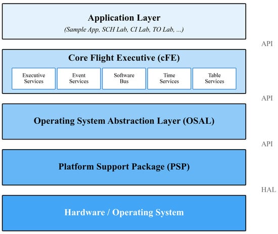
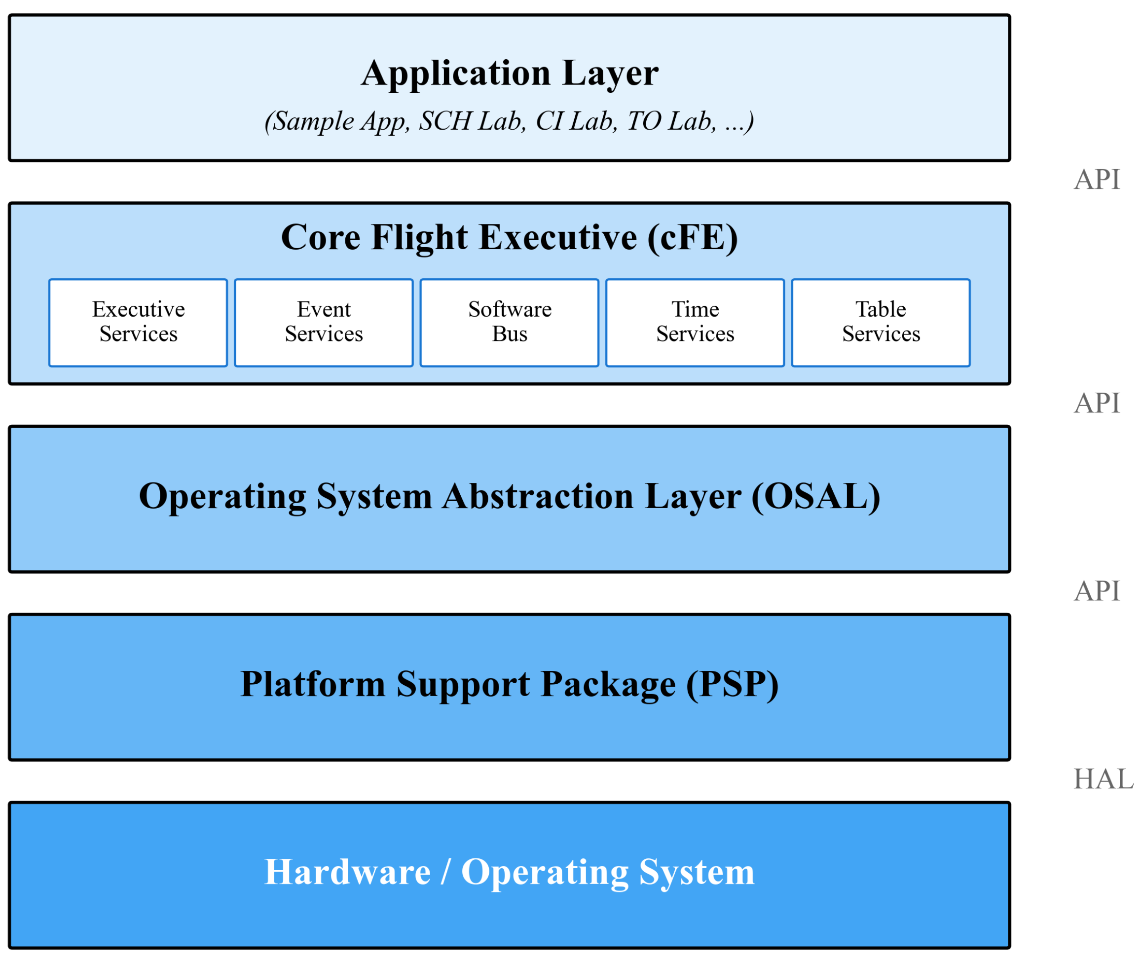
cFS employs a classic layered software architecture pattern, dividing the entire system into four independent but closely collaborative layers. From bottom to top, these are: Platform Support Package (PSP), Operating System Abstraction Layer (OSAL), core Flight Executive (cFE), and Application Layer. The core advantage of this layered architecture is that each layer depends only on the interfaces provided by the layer immediately below it, while hiding implementation details from upper layers, thereby achieving a high degree of modularity and portability [15,23]. Figure 1 illustrates the cFS layered architecture.
Figure 1.
cFS layered architecture.
3.1.1. Platform Support Package (PSP)
The PSP constitutes the hardware abstraction foundation of cFS, with responsibilities distinctly separate from the OSAL. While OSAL abstracts operating system primitives (tasks, semaphores, queues, file I/O), the PSP abstracts hardware-specific functionality including processor initialization sequences, memory map configuration, board-level peripheral access, and boot loading logic. This architectural separation is critical: PSP modifications address hardware differences, whereas OSAL modifications address OS kernel differences. This design significantly enhances system portability; when deploying cFS to a new hardware platform, only the PSP requires targeted adaptation or re-implementation, while upper-layer applications and middleware code can remain largely unchanged.
The PSP typically supports multiple hardware and operating system combinations, such as PC development environments based on Linux, real-time platforms using RTEMS, and aerospace-specific single-board computers running VxWorks. To achieve hardware abstraction, the PSP can be divided into the following core functional modules:
- Memory Management Subsystem: This module provides unified abstraction and management of physical memory resources, offering read/write access to different types of storage.
- Time Base and Timing Services: To meet the stringent requirements for time synchronization and scheduling in aerospace missions, this module provides high-precision, high-stability time references for the entire system.
- Processor Control and Reset Management: This module provides control capabilities for processor core states.
- Exception Handling and Runtime Monitoring: Integrates hardware-level exception handlers for capturing and processing processor exceptions such as memory access errors and illegal instructions.
3.1.2. Operating System Abstraction Layer (OSAL)
The OSAL is a key component in the cFS architecture for achieving cross-platform portability [12,24]. Its core design goal is to provide a unified Application Programming Interface (API) for upper-layer frameworks and applications that is independent of specific operating systems. Through this abstraction layer, applications can be deployed without modification on VxWorks, RTEMS, Linux, and other real-time and general-purpose operating systems.
The OSAL employs a layered architecture for implementation: the top layer is the common API interface layer, which clearly defines function prototypes and data types for all operating system services; the middle layer is the shared implementation layer, containing operating system-independent generic logic; the bottom layer is the operating system-specific adaptation layer, providing concrete implementations for different operating system kernels.
- Task Management Module: Provides basic execution unit abstraction, corresponding to threads or processes in the operating system, supporting task creation, scheduling, and lifecycle management.
- Synchronization Primitives: OSAL provides a series of synchronization primitives to address resource competition and synchronization requirements in multi-task environments.
- File System Services Module: Encapsulates differences in underlying file operations, providing unified file and directory management interfaces, ensuring consistent application access across different storage architectures.
3.1.3. Core Flight Executive (cFE)
The cFE is the core middleware layer of the cFS architecture, providing a complete, standardized set of fundamental runtime services for aerospace flight software. Built upon the OSAL, the five core services—Executive Services (ES), Event Services (EVS), Software Bus (SB), Time Services (TIME), and Table Services (TBL)—together constitute a unified framework environment supporting loosely coupled applications, configurable data, and standardized communication.
- Executive Services (ES): Serves as the control core of cFE, responsible for system boot initialization, application lifecycle management, and critical system resource coordination.
- Software Bus (SB): The cornerstone of inter-application communication in the cFE architecture, employing a classic publish–subscribe model that completely decouples message producers from consumers.
- Event Services (EVS): Provides standardized, telemetry-oriented event reporting mechanisms for the system.
- Time Services (TIME): Provides unified, reliable time references for the entire system, serving as the foundation for timestamp generation, scheduled task execution, and scientific data correlation.
- Table Services (TBL): Implements separation of flight software configuration data from executable code, enabling dynamic system behavior reconfiguration without recompilation.
3.2. Limitations Analysis for Resource-Constrained Environments
Despite its powerful functionality, cFS was originally designed for resource-rich processor platforms such as PowerPC or x86. When migrating to MCU environments commonly used in nanosatellites, fundamental conflicts arise between its inherent resource consumption and the strict constraints of MCUs.
3.2.1. OSAL Semantic Adaptation Gap for Lightweight RTOS
cFS achieves cross-platform portability through the OSAL, but its official implementations primarily target full-featured real-time operating systems such as VxWorks and RTEMS. Mainstream lightweight RTOSs (such as FreeRTOS and Zephyr) lack official support. The core difficulty in porting lies in satisfying the deep semantic contracts of OSAL interfaces, rather than simple API mapping. For example, OSAL requires mutexes to support recursive acquisition and priority inheritance, while native synchronization primitives in many lightweight RTOSs may only partially support these features or have different semantics [25].
3.2.2. Strong Dependency on Persistent File Systems
Multiple core services of cFS assume a standard file system as a prerequisite for operation. Executive Services depend on startup script files to load applications, and Table Services read configuration parameters from the file system. However, typical MCU on-chip Flash is unsuitable for frequent fine-grained file write operations, while introducing external storage increases system complexity and power consumption.
3.2.3. Memory-Intensive Characteristics of Core Services
The Software Bus message buffer pools, routing tables, and pipe management structures; Table Services’ double-buffering mechanism; and Executive Services’ application and task registries and Critical Data Store (CDS) together constitute significant baseline memory overhead. Even with minimal configuration, static memory requirements often exceed the 100 KB level. For MCUs with RAM resources measured in hundreds of kilobytes, this creates a fundamental system integration bottleneck before any business applications are loaded.
4. Key Porting Technologies and Implementation
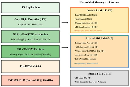
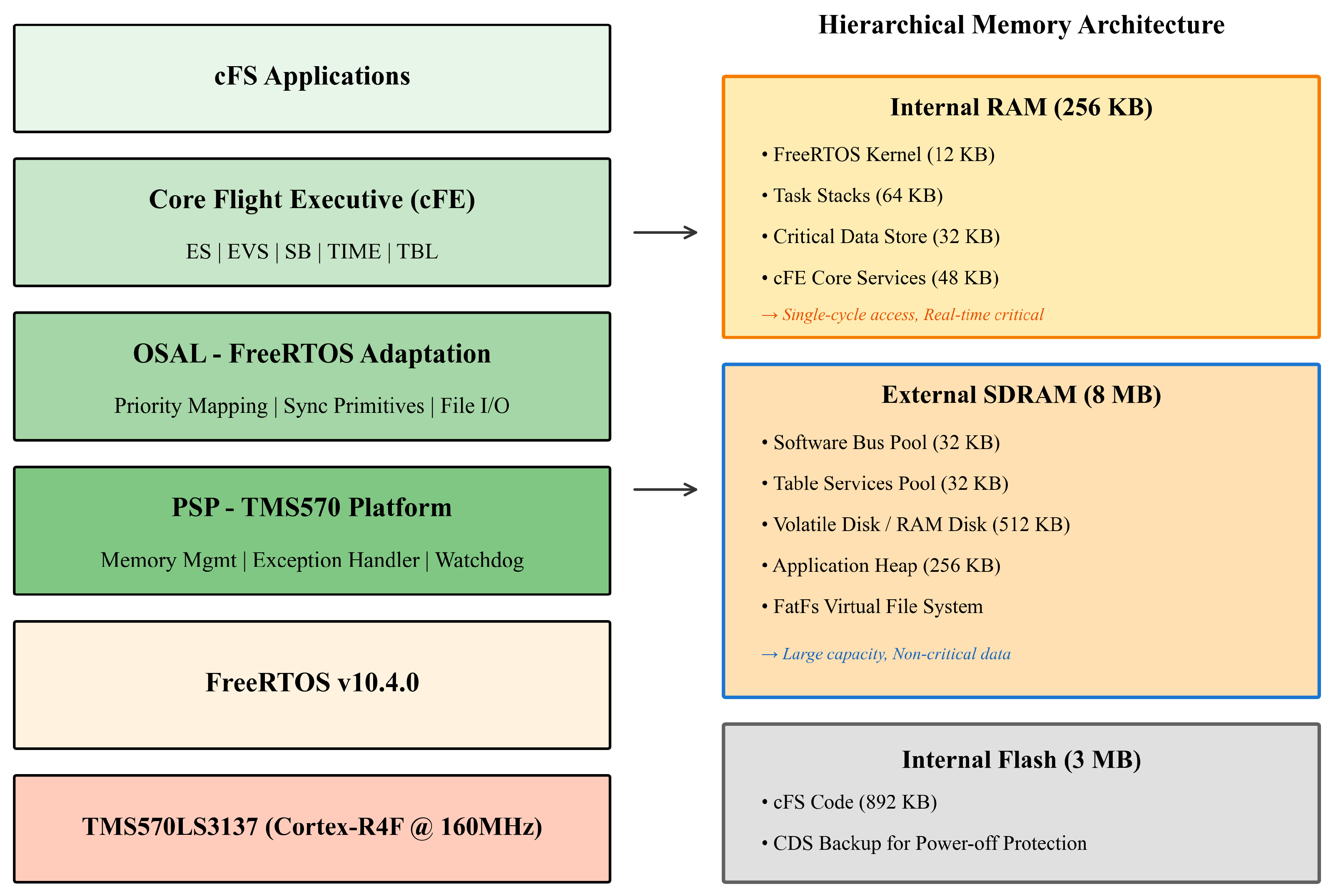
This section presents the specific design for porting cFS to the TMS570/FreeRTOS platform. Figure 2 illustrates the overall porting architecture.
Figure 2.
cFS porting architecture on TMS570/FreeRTOS platform.
4.1. Operating System Abstraction Layer Adaptation
The OSAL aims to shield differences in underlying operating systems and provide unified APIs for upper-layer applications. The adaptation for FreeRTOS (tms570-freertos) primarily addresses task model differences, priority mapping, and file system integration.
4.1.1. Task Scheduling and Priority Mapping
cFS employs a 256-level priority scheme where 0 represents the highest priority, while FreeRTOS uses a mechanism where higher numerical values indicate higher priority [21,26]. Prior research on real-time operating system performance for embedded controllers [27] has demonstrated that proper priority mapping is essential for maintaining deterministic scheduling behavior. This semantic inversion necessitates careful mapping to preserve scheduling correctness. The porting layer implements a priority transformation algorithm in os-impl-tasks.c:
freertos_priority = (configMAX_PRIORITIES - 1) -
(osal_priority * (configMAX_PRIORITIES - 1) / 255);
(osal_priority * (configMAX_PRIORITIES - 1) / 255);
Table 2 presents the priority mapping for representative cFS tasks, demonstrating that flight-critical tasks receive highest FreeRTOS priorities.
Table 2.
Priority mapping between cFS OSAL and FreeRTOS.
This mapping ensures flight-critical tasks (attitude control, timing) cannot be preempted by lower-priority telemetry or housekeeping tasks, preserving deterministic real-time behavior. The priority collision—where multiple OSAL priority values map to the same FreeRTOS priority due to integer division across the reduced priority range—is handled deliberately rather than treated as an error. Note that tasks within the same criticality class (e.g., TIME Tone Task and Attitude Control, both at FreeRTOS priority 6) are intentionally mapped to identical FreeRTOS priorities. This is a consequence of the integer-division mapping from 256 OSAL levels to configMAX_PRIORITIES FreeRTOS levels, and is by design: tasks sharing the same criticality class do not require strict mutual preemption. FreeRTOS schedules equal-priority tasks using round-robin time slicing (configUSE_TIME_SLICING = 1), guaranteeing fair CPU sharing among peers while collectively preventing preemption by any lower-priority task.
To facilitate reproduction of the porting effort, Table 3 lists the key FreeRTOS configuration parameters used in this work.
Table 3.
Key FreeRTOS configuration parameters.
4.1.2. Synchronization Primitives and Communication Mechanisms
To ensure reliable cFS operation on the target platform, the core synchronization mechanisms it depends upon must be completely adapted to the FreeRTOS environment.
- Mutexes: OSAL requires mutexes supporting recursive acquisition and priority inheritance protocol. FreeRTOS recursive mutexes satisfy these requirements; however, a critical limitation exists: FreeRTOS implements simplified priority inheritance that does not maintain a complete priority stack when multiple mutexes are held simultaneously. If a cFS application holds both an SD card access mutex and a Software Bus transmission mutex, priority disinheritance may not function correctly until all locks are released. Mission designers should minimize nested mutex acquisition in time-critical paths.
- Binary Semaphores: Employed for inter-task event notification and synchronization. Semantic equivalence with FreeRTOS binary semaphores enables direct mapping.
- Counting Semaphores: Utilized for managing pools of homogeneous resources. The adaptation layer employs FreeRTOS counting semaphores with maximum count configured to system limits.
- Condition Variables: FreeRTOS lacks native condition variable support. Analysis of cFS core services reveals that condition variables are used exclusively in optional file-system drivers and network stack components not required for basic satellite operations. Consequently, this implementation provides stub functions returning “not implemented” status codes, with no impact on core cFE functionality.
4.1.3. File System and RAM Disk Integration
Given the absence of mechanical hard drives on the target platform, this work utilizes the FatFs library to construct a volatile virtual file system (RAM Disk) in external SDRAM. The OSAL file service adaptation layer completes the mounting of this virtual file system during initialization and provides it as a standard file system mount point for upper-layer cFS services.
4.2. Platform Support Package and Hierarchical Memory Architecture
The PSP layer is responsible for hardware initialization, watchdog management, and exception handling. Addressing the severe challenge of limited TMS570 internal RAM capacity [8,9,28], this research designs a hierarchical memory management architecture based on address space partitioning.
4.2.1. SDRAM Initialization During Boot
External SDRAM must be initialized before the PLL is configured, as per TI errata EMIF#5 (EMIF clock must remain below 40 MHz during SDRAM initialization) [22]. The boot sequence proceeds as follows:
- 1.
- The HALCoGen-generated startup code calls the SDRAM initialization function before PLL configuration, ensuring the EMIF clock is at the default low-frequency oscillator rate.
- 2.
- The initialization function programs the SDRAM timing register, self-refresh exit timing, and configuration register for 16-bit data bus, CAS latency 3, and 256-element page size.
- 3.
- A dummy read from the SDRAM base address triggers the hardware initialization sequence; the processor stalls until initialization completes.
- 4.
- The refresh rate register is set to the operational value, and SDRAM is placed in self-refresh mode until PLL configuration is completed.
- 5.
- After PLL lock, the main function exits self-refresh mode by clearing bit 31 of the SDRAM control register, making SDRAM available at the full EMIF bus frequency.
This sequence guarantees that SDRAM is fully initialized and accessible before FreeRTOS scheduler start and CFE_PSP_EarlyInit(), which maps cFS data structures into the SDRAM address space.
4.2.2. Memory Resource Conflicts and Dual-Layer Layout Strategy
The cFS framework contains multiple core service components requiring substantial memory: Software Bus message buffer pools (32–128 KB), Table Services double buffers (32–64 KB), Critical Data Store (CDS, 32–128 KB), and Volatile Disk (64–512 KB). The minimum configuration of these components alone requires approximately 160 KB, approaching 65% of TMS570’s total internal RAM.
To address these conflicts, this paper proposes an “internal RAM + external SDRAM” dual-layer hybrid storage strategy with explicit consideration of access latency implications:
1. High-Frequency Access Zone (Internal RAM): Allocated for FreeRTOS kernel objects, task stacks, interrupt vector tables, and CDS. The TMS570’s internal RAM provides single-cycle access latency, ensuring deterministic task switching and interrupt response times. This placement is essential for maintaining hard real-time guarantees.
2. Large-Capacity Data Zone (External SDRAM): Allocated for large, latency-tolerant cFS data structures. External SDRAM connected via the 16-bit EMIF interface exhibits access latencies approximately 6–8× higher than internal TCM. The PSP maps the following regions to SDRAM base address (0x80000000) during CFE_PSP_EarlyInit:
- Volatile Disk (512 KB): Virtual file system storage.
- Memory Pools (SB/TBL, 64 KB total): Software Bus and Table Services buffer pools.
Causal Relationship: The memory pressure from cFS core components forces utilization of external SDRAM, which increases cycles-per-instruction (CPI) for memory-intensive operations. Experimental quantification of this latency penalty is presented in Section 5.2.
This strategy releases approximately 96 KB of internal RAM (37.5% of TMS570’s internal RAM), sufficient to support an additional 8–10 FreeRTOS tasks or significantly increase critical task stack depth.
As shown in Table 4, the remaining 96 KB of internal RAM is reserved for mission-specific applications. To provide context, the six satellite simulation applications deployed in this work (attitude control, power management, telemetry, payload processing, spacecraft management, and data acquisition) collectively consume approximately 48 KB of task stacks (8 KB per task) from this budget. The remaining 48 KB is available for additional application tasks, increased stack depths for computationally intensive algorithms, or mission-specific data buffers. For missions requiring more extensive application memory, the Application Heap in SDRAM (256 KB) provides additional capacity for latency-tolerant dynamic allocations.
Table 4.
Memory allocation of ported cFS system.
Table 4 presents the detailed memory allocation for the ported cFS system.
4.2.3. Exception Capture and Reset Retention
The PSP implements a customized exception handler function CFE_PSP_ ExceptionHandler, which intercepts ARM Cortex-R4F Data Abort and Prefetch Abort exceptions. Upon exception occurrence, the handler preserves the complete exception context (general-purpose registers R0–R12, stack pointer, link register, program counter, and CPSR) along with fault status registers (DFSR, DFAR for data aborts; IFSR, IFAR for prefetch aborts) to a designated reset–retention memory region at a fixed RAM offset protected from normal initialization.
Following system restart, cFE Executive Services retrieves this preserved context to generate diagnostic telemetry, enabling post-mortem analysis of software faults without requiring hardware debugging interfaces.
4.2.4. Memory Optimization Strategies
To accommodate cFS within the 256 KB RAM constraint, the following optimization strategies were implemented:
Memory Safety Mechanisms. Beyond static allocation and stack sizing, three additional mechanisms address runtime memory safety:
(1) Stack overflow detection. FreeRTOS is configured with stack overflow checking at level 2, which fills each task stack with a known watermark pattern at creation and verifies the last 16 bytes at every context switch. Upon detection of corruption, the overflow hook callback logs the offending task name and triggers a controlled reset via the PSP exception path. Combined with the 110% preventive stack sizing (Table 5), this provides both detection and mitigation against stack overrun.
Table 5.
Memory optimization techniques.
(2) MPU-based memory region protection. The Cortex-R4F Memory Protection Unit (MPU) is configured with separate access regions: internal RAM (read/write), external SDRAM (read/write, non-cacheable), and Flash (read-only/execute). Any access violation—such as a wild pointer writing to Flash or an out-of-bounds SDRAM access—triggers a Data Abort exception captured by the PSP exception handler (Section 4.2.3). This provides hardware-enforced boundaries between memory regions, though per-task isolation is not available without an MMU.
(3) ECC handling policy. TMS570 provides hardware SECDED ECC on internal RAM and Flash. Single-bit correctable errors are automatically corrected by hardware; the Error Signaling Module (ESM) logs these as Group 1 events, and the PSP increments a software counter reported in cFE housekeeping telemetry for ground monitoring. Double-bit uncorrectable errors trigger ESM Group 3 exceptions, leading to the abort-and-reset path described in Section 4.2.3. External SDRAM connected via EMIF does not have hardware ECC protection—this is a hardware limitation motivating the placement of safety-critical data structures in ECC-protected internal RAM rather than SDRAM.
5. Evaluation and Verification
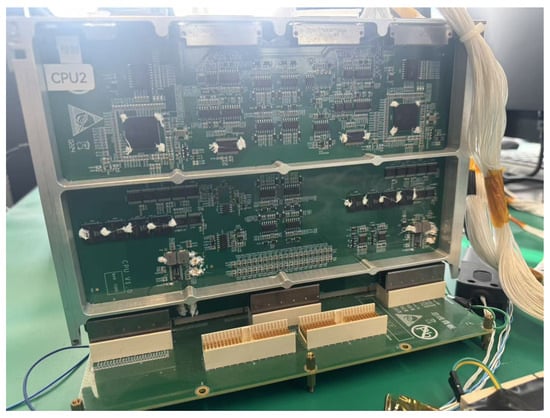
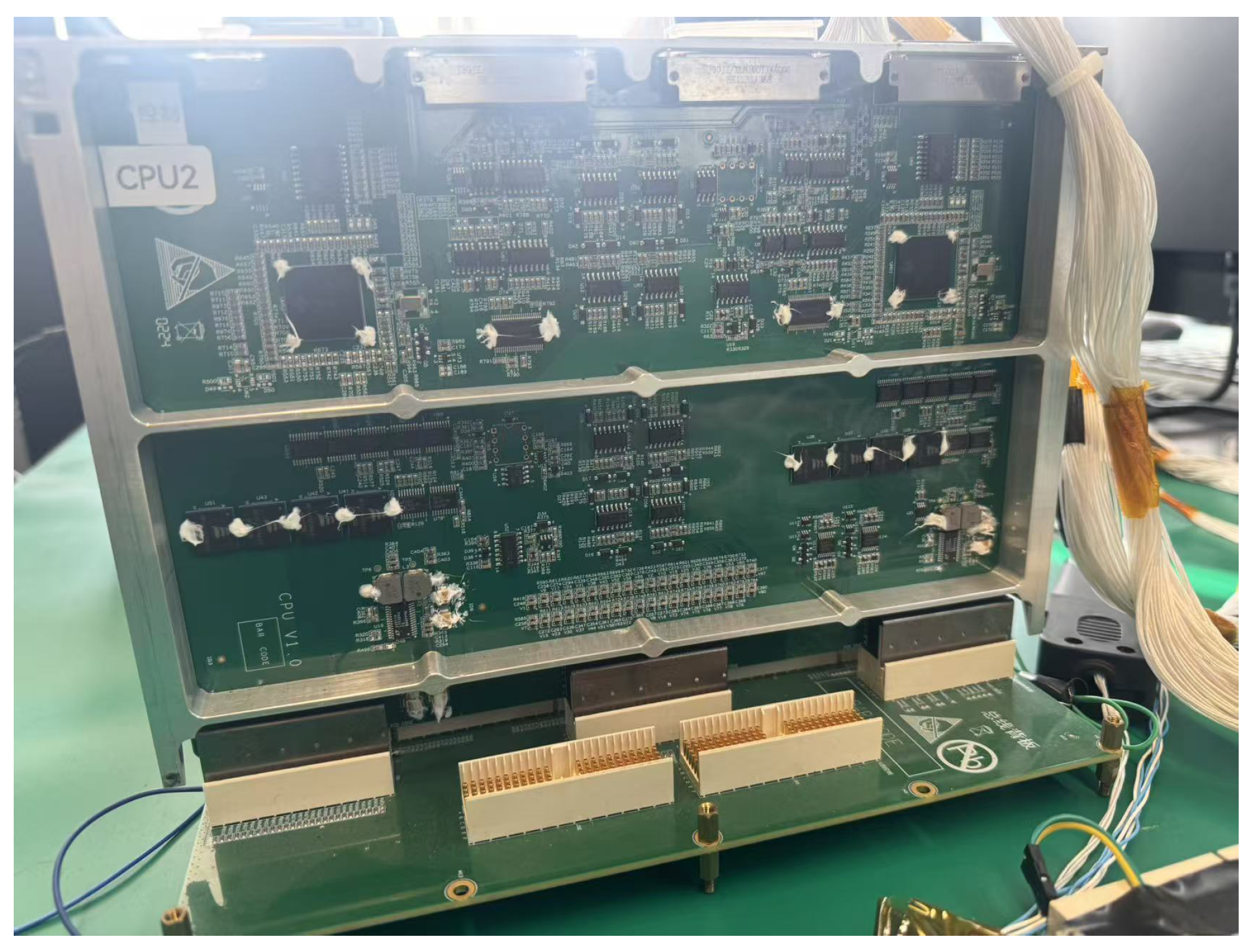
To systematically verify whether the key porting technologies achieve design objectives, this paper designs targeted performance tests and functional verification. The experimental hardware platform is shown in Figure 3.
Figure 3.
Nanosatellite simulation hardware setup.
5.1. Experimental Environment
The experimental environment consists of:
- Hardware: TMS570LS3137, 160 MHz Cortex-R4F, 3 MB Flash, 256 KB RAM [22].
- Software: cFS “Caelum” version, FreeRTOS v10.4.0.
- Tools: Python 3.9, MobaXterm v23.2, TI Code Composer Studio v10.
- Flight Software: Successfully ported flight software with simulation scenario applications including memory monitoring, critical state monitoring, telemetry system, data acquisition system, power management system, and attitude determination and control system.
The system underwent a 72 h continuous operation test under simulated mission loads. During this period, the following metrics were monitored:
- Task execution: Over 2.5 million task cycles completed without failure.
- Message throughput: 156,000+ Software Bus messages processed.
- Memory stability: No memory leaks detected; heap usage remained constant at 78%. Memory leak absence was verified through two complementary mechanisms: (1) the cFE Executive Services housekeeping telemetry reports the remaining free bytes in each memory pool (Software Bus pool, Table Services pool, and ES memory pool) at 1 Hz intervals—these values were logged throughout the 72 h test and confirmed to remain constant after the initial startup transient (first 30 s); (2) the FreeRTOS xPortGetFreeHeapSize() function was sampled periodically via a dedicated monitoring task, confirming that the kernel heap free size remained at a fixed value of 21,504 bytes (22% of the 96 KB total) from 1 min through 72 h. The combination of stable pool-level and kernel-level heap metrics across 2.5 million task cycles provides strong evidence against cumulative memory leaks.
- Watchdog resets: Zero unplanned resets occurred.
- Event logging: 12,400+ events recorded with correct timestamps.
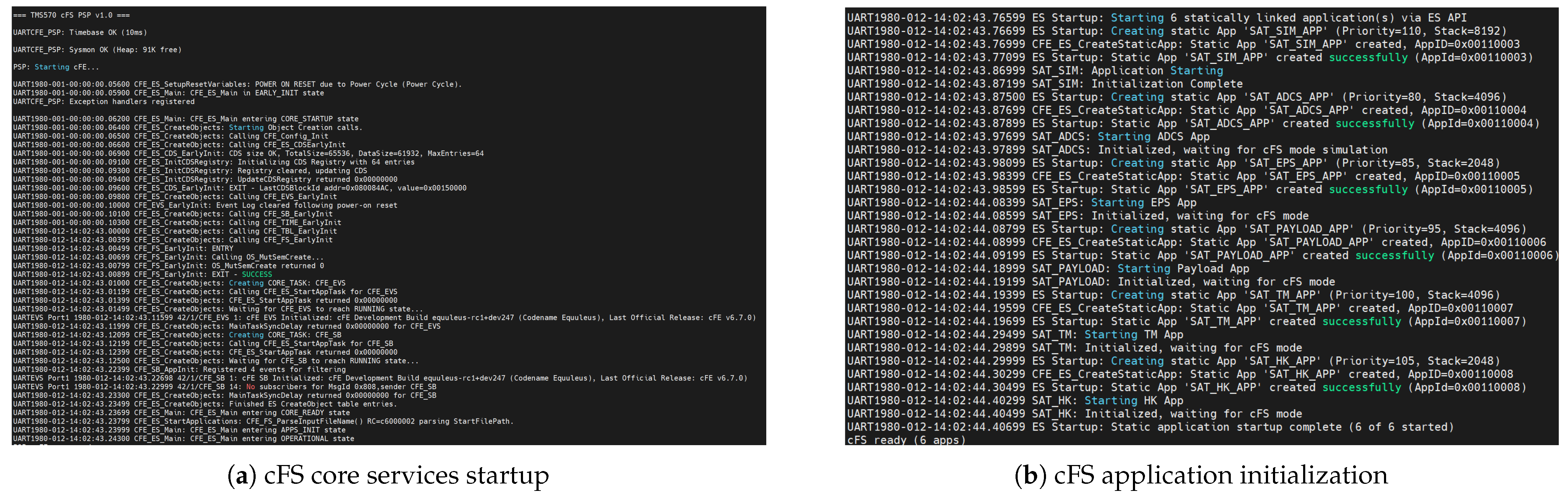
Figure 4 shows the serial output after successful system startup.
Figure 4.
Serial output after successful porting: (a) cFS core services startup sequence showing PSP, OSAL, and cFE initialization; (b) cFS application initialization showing successful loading of satellite simulation applications.
5.2. Software Bus Performance Comparison Across Different Storage Media
To validate the hierarchical architecture design and quantify the performance implications of memory placement decisions, systematic comparative experiments were conducted for cFS Software Bus operations across different storage media.
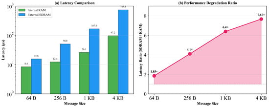
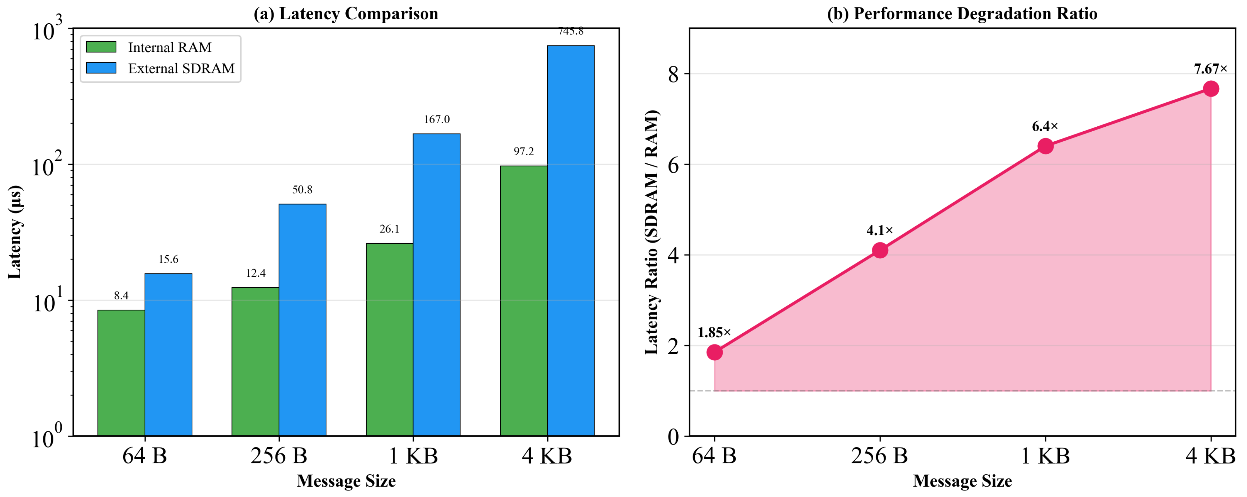
Measurements employed an RTI timer (466 kHz, resolution approximately 2.15 s) as the timing reference [29]. Each configuration executed 1000 iterations; statistical analysis computed mean values and standard deviations. Testing encompassed four representative message sizes: 64 B, 256 B, 1 KB, and 4 KB. The results are presented in Figure 5 and Table 6.
Figure 5.
Software Bus performance comparison between RAM and SDRAM for different message sizes.
Table 6.
Software Bus latency comparison (RAM vs. SDRAM, ).
Experimental Observations:
- Small Message Scenario (64 B): Mean RAM latency measured 8.45 s; SDRAM latency measured 15.62 s (difference: 7.17 s). Fixed-cost operations (message header parsing, routing table lookup) dominate execution time, limiting the observable memory access penalty.
- Medium Message Scenario (256 B–1 KB): Latency differentials increase substantially. At 1 KB message size, SDRAM latency reaches 167.04 s—6.4× the corresponding RAM latency (26.10 s). Data transfer overhead supersedes fixed costs.
- Large Message Scenario (4 KB): RAM configuration exhibits 97.24 s latency versus 745.82 s for SDRAM (7.67× ratio). Memory bandwidth constraints become the dominant performance-limiting factor, validating the causal relationship between memory placement and execution time.
Statistical Reliability Analysis:
Table 7 presents the detailed statistical characterization from 1000-iteration measurements. Several notable patterns emerge regarding measurement determinism. First, all RAM configurations exhibit low coefficient of variation (CV ≤ 7.9%), confirming the high timing determinism of single-cycle internal RAM access. Second, SDRAM latency at 64 B shows the highest CV (10.1%), with a worst-case outlier of 44.71 s (2.86× the mean)—this variability is attributed to SDRAM controller refresh cycles and bus arbitration contention at small transfer sizes. Third, for large transfers (≥1 KB), both RAM and SDRAM exhibit very low CV (≤2.5%), indicating that bandwidth-dominated operations yield highly predictable latency. These results demonstrate that the hierarchical memory architecture provides sufficient timing predictability for real-time scheduling: even the worst-case observed SDRAM latency at 4 KB (787.93 s) remains well within a 1 ms scheduling deadline at typical 1 kHz task rates.
Table 7.
Detailed statistical characterization of Software Bus latency ( iterations).
5.3. Performance Comparison of Satellite Tasks Between cFS Framework and Pure FreeRTOS
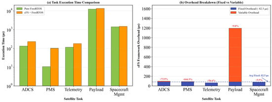
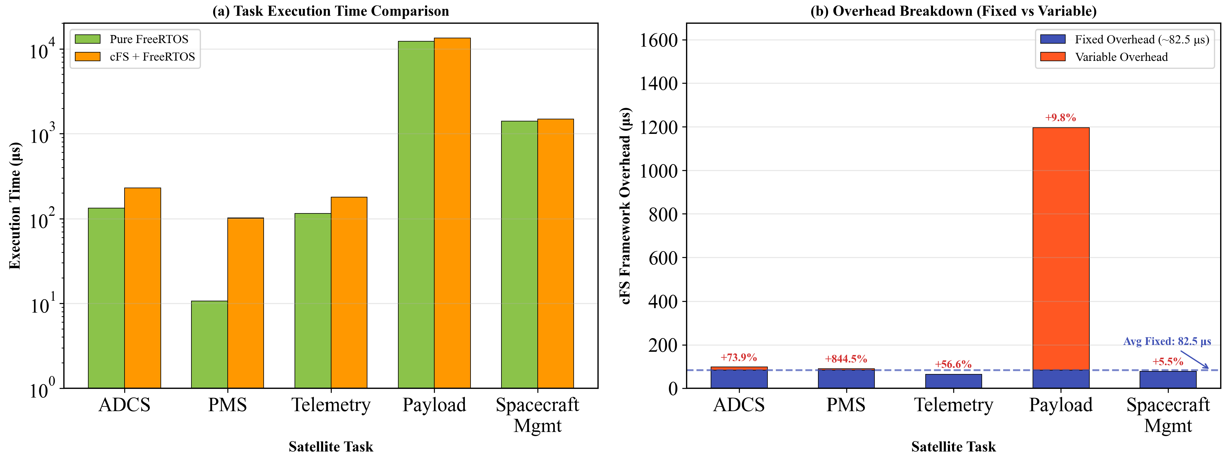
To quantify the runtime overhead introduced by the cFS flight software framework, this paper designs comparative experiments executing identical nanosatellite typical task loads [30,31] in both cFS+FreeRTOS integrated environment and pure FreeRTOS bare-metal environment. The results are summarized in Figure 6 and Table 8.
Figure 6.
Performance comparison of nanosatellite tasks between cFS framework and FreeRTOS.
Table 8.
Satellite task execution time and overhead comparison.
Fixed Overhead Quantification: Statistical analysis across the five task categories reveals a consistent per-invocation base overhead: four tasks exhibit absolute overhead in the range 64.7–97.7 s (mean: 82.5 s), isolating the framework’s fixed cost for a single task cycle. The Payload Data Processing task shows a larger absolute overhead (1196 s) attributable to additional cFS service interactions per datum within each processing cycle. The 82.5 s base overhead comprises the following components:
- cFE Executive Services: task registration validation and status maintenance.
- Software Bus: message header construction, routing table traversal, and pipe management.
- Time Services: spacecraft time acquisition and timestamp formatting.
- Event Services: event filtering predicates and telemetry packet formatting.
- FreeRTOS scheduler: context switch and priority evaluation.
Implications for Mission Design: The framework abstraction introduces measurable computational overhead; however, this overhead amortizes effectively for tasks with execution times exceeding 1 ms. For ADCS loops at 50–200 Hz, the overhead remains below 2% of the period budget (see Table 9), posing no scheduling concern. For lightweight, high-frequency tasks (e.g., 100 Hz control loops), designers should consider direct FreeRTOS implementations where cFS service abstraction is not required.
Table 9.
Framework overhead budget at high control frequencies.
5.4. Discussion
The experimental results validate the feasibility of our porting approach while revealing important trade-offs and limitations that warrant discussion.
5.4.1. Memory Architecture Trade-Offs
The hierarchical memory strategy resolves the RAM capacity constraint while introducing quantifiable access latency penalties for SDRAM-resident data structures. As demonstrated in Table 6, large message processing on SDRAM exhibits latencies up to 7.67× those of internal RAM operations.
Causal Analysis: The latency differential arises from multiple factors: (1) EMIF bus arbitration overhead, (2) SDRAM row activation and precharge cycles, and (3) lack of caching for external memory regions on Cortex-R4F. Extended execution times for SDRAM-resident operations correspondingly increase the temporal window during which the processor remains vulnerable to transient faults in radiation environments. This trade-off is acceptable for latency-tolerant operations (telemetry buffering, table loading, event logging) but mandates placement of real-time critical data structures in internal RAM.
Runtime Memory Footprint. At steady state, the measured runtime memory consumption confirms the design-time analysis from Table 4. The 160 KB internal RAM baseline comprises: FreeRTOS kernel (12 KB), eight cFS system task stacks (64 KB), Critical Data Store (32 KB), interrupt vectors (4 KB), and cFE core services (48 KB). The remaining 96 KB serves as the FreeRTOS dynamic heap, from which the six satellite application task stacks (≈48 KB at 8 KB each) and other runtime allocations are drawn; the heap operates at 78% utilization with 21,504 bytes remaining free throughout the 72 h stability test, leaving ≈21 KB of runtime margin for additional tasks or deeper stacks. The external SDRAM (832 KB total) accommodates Software Bus and Table Services buffer pools (64 KB), the Volatile Disk file system (512 KB), and the application heap (256 KB).
Comparison with Prior MCU-Based cFS Deployments. The pioneering work of França et al. [14] demonstrated a complete cFS deployment on an STM32F767ZI (Cortex-M7, 512 KB RAM, 2 MB Flash) running FreeRTOS, including all five cFE core services, a FAT-based RAM Disk, cFS lab applications, and preliminary neutron irradiation reliability testing. Because their study focused on radiation reliability assessment rather than performance benchmarking, a direct numerical comparison of latency or framework overhead is not available; the discussion below therefore addresses platform and analytical differences. Building on the foundation laid by [14], the present work targets a more constrained and safety-oriented hardware profile: the TMS570 provides only 256 KB internal RAM (half of the STM32F767ZI’s 512 KB) and must supplement it with external SDRAM via a 16-bit EMIF bus, which introduces a latency–capacity trade-off that motivates the hierarchical memory architecture quantified in Table 6 and Table 7. Additionally, the TMS570 platform provides ASIL-D safety certification (lockstep, ECC), adding a safety dimension not present in the STM32F767ZI environment. Our work also includes mission-representative satellite application simulations (ADCS, TTC, power management, etc.) and a 72 h continuous stability validation. The quantitative results reported here (non-linear SDRAM penalty 1.85–7.67×, 82.5 s framework overhead, 72 h stability) complement the radiation reliability findings of [14] by adding performance characterization data that may serve as a reference baseline for future MCU-class cFS deployments.
5.4.2. Framework Overhead Analysis
The measured 82.5 s fixed overhead per task execution may appear significant for lightweight tasks (e.g., Power Management shows +844.5% overhead). However, this percentage is misleading for tasks with very short baseline execution times: the Power Management task’s pure FreeRTOS execution time of only 10.73 s means the absolute overhead increase is merely 90.57 s—comparable to other tasks. This overhead becomes negligible for computationally intensive tasks—Payload Data Processing shows only +9.8% overhead. For typical satellite control loops operating at 1–10 Hz (100–1000 ms periods), the framework overhead represents less than 0.1% of the available execution budget, which is acceptable for most mission scenarios.
Scalability to High-Frequency Control Loops. A natural question is whether the 82.5 s overhead remains acceptable for higher-rate tasks such as attitude determination and control (ADCS) loops running at 50–200 Hz. Table 9 presents the overhead analysis across representative control frequencies.
At 200 Hz, the 82.5 s framework overhead consumes only 1.65% of the 5 ms period, leaving 4.92 ms for ADCS computation. Given that the measured ADCS task execution time (including cFS overhead) is 229.82 s (Table 8), the total CPU utilization per ADCS cycle at 200 Hz would be approximately 4.6%, well within acceptable bounds. These results confirm that the cFS framework overhead does not pose a scheduling constraint for ADCS loops up to 200 Hz on the TMS570 platform.
These findings align with observations from the FloripaSat-1 mission [17], which documented similar embedded system challenges when deploying flight software on resource-constrained platforms. The FloripaSat-1 experience demonstrated that careful software architecture design and memory optimization are essential for mission success, reinforcing the validity of our hierarchical memory approach.
5.4.3. Robustness Considerations: Overload, Fault Tolerance, and Interrupt Latency
While the primary experiments in this paper focus on nominal operating conditions, the robustness of the ported system under anomalous conditions is an important consideration for mission deployment. This section provides an architectural analysis based on the known properties of cFS, FreeRTOS, and the TMS570 hardware platform.
Overload Behavior. The cFS Software Bus employs bounded-depth message pipes with a configurable maximum depth per pipe. When a subscriber’s pipe reaches capacity, CFE_SB_TransmitMsg returns the status code CFE_SB_BUF_ALOC_ERR to the caller without blocking, ensuring that a slow or stalled consumer cannot induce back-pressure on the sending task. Under FreeRTOS fixed-priority preemptive scheduling, this non-blocking design guarantees that higher-priority tasks continue to execute even when lower-priority pipes overflow. During the 72 h stability test (Section 5.1), all Software Bus pipes operated within configured depth limits with zero overflow events under the nominal 1 Hz workload. Systematic stress testing with controlled message rate escalation (e.g., 5× and 10× nominal throughput) has not yet been performed and is identified as future work.
Hardware-Level Fault Tolerance. The TMS570 provides several hardware safety mechanisms that complement the software-level protections of cFS:
- Dual-core lockstep: Two CPU cores execute identical instruction streams in parallel; a hardware comparator raises a non-maskable interrupt (NMI) upon any divergence, enabling detection of transient computational faults within a single clock cycle [28].
- ECC-protected memories: Both internal RAM and Flash incorporate single-error-correct, double-error-detect (SECDED) ECC, with correctable errors logged via the Error Signaling Module (ESM) and uncorrectable errors triggering an abort exception [22].
- PSP exception handler: As described in Section 4.2.3, the ported PSP captures Data Abort and Prefetch Abort exceptions, preserves the full register context (R0–R12, SP, LR, PC, CPSR, and fault status registers) to a reset–retention memory region, and triggers a controlled reset. Upon restart, cFE Executive Services retrieves this context and generates diagnostic telemetry for ground-based post-mortem analysis.
These mechanisms provide a layered foundation for fault detection and recovery. However, the current work has not performed systematic fault injection campaigns (e.g., software-implemented bit-flip injection into RAM or register corruption) to validate the end-to-end detection coverage and recovery latency of this chain. Such testing is planned as future work.
Interrupt Latency. For the Cortex-R4F core at 160 MHz, the worst-case interrupt response time comprises: (1) pipeline flush and state saving (≤12 cycles), (2) vector table fetch (1–2 cycles), and (3) exit from the longest FreeRTOS kernel critical section. FreeRTOS uses the basepri masking mechanism on ARM Cortex-R, ensuring that interrupts above a configurable priority threshold are never disabled by kernel operations. Based on the ARM Cortex-R4F Technical Reference Manual and FreeRTOS kernel analysis, the worst-case interrupt latency is estimated at <2 s (approximately 320 CPU cycles at 160 MHz) for the highest-priority interrupt level. This estimate is consistent with published measurements on comparable Cortex-R platforms [21]. Direct measurement using GPIO toggling with oscilloscope capture is planned for future characterization.
5.4.4. Limitations and Future Work
Several limitations should be acknowledged:
- (1)
- Radiation Testing: Although TMS570’s ASIL-D safety mechanisms (lockstep, ECC) provide partial mitigation against single-event effects, ASIL-D certification alone is insufficient for space qualification. Our current validation does not include radiation environment testing. Mission-specific radiation characterization—including total ionizing dose (TID) and single-event effect (SEE) testing—is mandatory before flight deployment and is planned as a priority for future work.
- (2)
- Stress and Fault Injection Testing: The 72 h validation was conducted under nominal workloads. Systematic overload testing with controlled message rate escalation and software-implemented fault injection (register corruption, memory bit-flips) are needed to quantify robustness boundaries and validate the end-to-end fault detection and recovery chain.
- (3)
- Interrupt Latency Measurement: The interrupt latency analysis presented in Section 5.4 is based on architectural estimation. Direct measurement using hardware instrumentation (GPIO toggling with oscilloscope capture) is required to validate the estimated <2 s bound under realistic ISR workloads including nested interrupts and DMA activity.
- (4)
- Dynamic Application Loading: The current implementation uses static linking. Supporting runtime application loading would enhance operational flexibility but requires careful memory management.
- (5)
- Power Consumption: Power measurements were not included in this study. For power-constrained missions, detailed power profiling of cFS services under various operational modes would be valuable.
- (6)
- Multi-core Extension: TMS570 features dual-core lockstep for safety, but cFS currently runs on a single logical core. Exploring asymmetric multiprocessing configurations could further enhance performance.
5.4.5. Portability to Other MCU Platforms
The porting methodology presented in this work is designed to be generalizable. The key adaptation components—OSAL for FreeRTOS and hierarchical memory PSP—can be reused on other Cortex-R/M series MCUs with minimal modifications. Specifically:
- Cortex-R5 platforms (e.g., TMS570LC43xx): Direct compatibility expected with increased RAM availability.
- Cortex-M7 platforms (e.g., STM32H7): Requires MPU configuration adjustments but core OSAL remains applicable.
- RISC-V MCUs: Would require new OSAL implementation but PSP concepts remain valid.
5.4.6. Recommendations for Mission Deployment
Based on experimental observations, the following guidelines are suggested for teams considering cFS deployment on resource-constrained platforms:
- (1)
- Memory planning: Internal RAM allocation of at least 160 KB for cFS core services is recommended; SDRAM capacity should be planned according to application-specific requirements.
- (2)
- Critical path identification: Time-critical data structures (attitude control message pools, sensor data buffers) should be placed in internal RAM to maintain sub-100 s latency bounds.
- (3)
- Task design: Application tasks with execution times exceeding 1 ms are recommended to minimize relative framework overhead impact.
- (4)
- Incremental testing: Independent validation of each cFE service prior to full system integration is recommended.
- (5)
- Endianness handling: TMS570 employs word-invariant big-endian (BE32) format. Applications should enforce network byte order for Software Bus message payloads and utilize the hardware REV instruction for efficient byte swapping when interfacing with little-endian ground systems.
Note: Per NASA-STD-8739.8 software development requirements, the term “shall” denotes mandatory requirements, “should” denotes recommendations, and “may” denotes optional provisions. The above items constitute engineering recommendations based on experimental observations.
6. Conclusions
This paper addresses the resource-constrained and reliability-demanding characteristics of nanosatellite platforms, investigating key technologies for porting NASA cFS to the TMS570 safety microcontroller and FreeRTOS real-time operating system. The core contributions include the following:
- (1)
- Precise Operating System Interface Adaptation: Ensures correctness and real-time performance of cFE services in multi-task environments through accurate priority mapping, synchronization primitive implementation, and OSAL API adaptation.
- (2)
- Hierarchical Hybrid Memory Architecture: Resolves conflicts between massive memory requirements of Software Bus message pools and MCU on-chip RAM, releasing approximately 37.5% of on-chip resources on the TMS570 platform with only 256 KB RAM.
- (3)
- Startup and Loading Mechanism Reconstruction: Eliminates dynamic symbol resolution overhead, achieving deterministic fast startup.
- (4)
- Virtualized Storage Integration: Provides standard file operation interfaces for cFS, compensating for the target platform’s lack of physical hard drives.
Performance Evaluation Summary:
- Comparative experiments between on-chip RAM and off-chip SDRAM provide data support for the hierarchical memory strategy.
- Task execution overhead comparison experiments quantify the fixed overhead introduced by the cFS framework (approximately 82.5 s), proving it acceptable within typical task cycles.
- For small messages (64–256 B), Software Bus latency on internal RAM is controlled within 15 s, meeting real-time requirements for critical tasks such as attitude control.
- Framework overhead analysis across control frequencies from 1 Hz to 200 Hz confirms that ADCS loops up to 200 Hz consume less than 5% CPU utilization per cycle, including cFS overhead.
This work demonstrates the feasibility of lightweight cFS porting to resource-constrained MCU platforms, forming a reusable technical pathway that provides practical reference for rapid deployment of reliable, extensible onboard software systems on similar platforms.
Future work will focus on radiation environment validation through total ionizing dose (TID) and single-event effect (SEE) testing, systematic stress and fault injection campaigns, direct interrupt latency measurement, power consumption profiling under various operational modes, and extension to other safety-certified MCU families including Cortex-R5 and RISC-V platforms.
Author Contributions
Conceptualization, Q.W. and M.X.; methodology, Q.W.; software, Q.W.; validation, Q.W.; formal analysis, Q.W.; investigation, Q.W.; resources, M.X.; data curation, Q.W.; writing—original draft preparation, Q.W.; writing—review and editing, M.X.; visualization, Q.W.; supervision, M.X.; project administration, M.X. All authors have read and agreed to the published version of the manuscript.
Funding
This research received no external funding.
Institutional Review Board Statement
Not applicable.
Informed Consent Statement
Not applicable.
Data Availability Statement
The data presented in this study are available on request from the corresponding author.
Acknowledgments
The authors would like to thank the open-source communities of NASA cFS and FreeRTOS for providing the foundational software frameworks used in this research.
Conflicts of Interest
The authors declare no conflicts of interest.
Abbreviations
The following abbreviations are used in this manuscript:
| cFS | core Flight System |
| cFE | core Flight Executive |
| OSAL | Operating System Abstraction Layer |
| PSP | Platform Support Package |
| ES | Executive Services |
| EVS | Event Services |
| SB | Software Bus |
| TIME | Time Services |
| TBL | Table Services |
| MCU | Microcontroller |
| RTOS | Real-Time Operating System |
| RAM | Random Access Memory |
| SDRAM | Synchronous Dynamic RAM |
| ECC | Error Correction Code |
| CDS | Critical Data Store |
| ASIL | Automotive Safety Integrity Level |
| TCM | Tightly Coupled Memory |
| EMIF | External Memory Interface |
| XIP | Execute-in-Place |
| CPI | Cycles Per Instruction |
| BE32 | Big-Endian 32-bit (Word-Invariant) |
References
- Cratere, A.; Gagliardi, L.; Sanca, G.A.; Golmar, F.; Dell’Olio, F. On-Board Computer for CubeSats: State-of-the-Art and Future Trends. IEEE Access 2024, 12, 99537–99569. [Google Scholar] [CrossRef] [Scilit]
- Shiroma, W.A.; Martin, L.K.; Akagi, J.M.; Akagi, J.T.; Wolfe, B.L.; Fewell, B.A.; Ohta, A.T. CubeSats: A bright future for nanosatellites. Open Eng. 2011, 1, 9–15. [Google Scholar] [CrossRef] [Scilit]
- Sweeting, M.N. Modern small satellites-changing the economics of space. Proc. IEEE 2018, 106, 343–361. [Google Scholar] [CrossRef] [Scilit]
- Bouwmeester, J.; Guo, J. Survey of worldwide pico-and nanosatellite missions, distributions and subsystem technology. Acta Astronaut. 2010, 67, 854–862. [Google Scholar] [CrossRef] [Scilit]
- Toptsis, M.; Karkanis, N.; Giannakoulas, A.; Kaifas, T. A Review of Embedded Software Architectures for Multi-Sensor Wearable Devices: Sensor Fusion Techniques and Future Research Directions. Electronics 2026, 15, 295. [Google Scholar] [CrossRef] [Scilit]
- McComas, D.; Wilmot, J.; Cudmore, A. The Core Flight System (cFS) community: Providing low cost solutions for small spacecraft. In Proceedings of the 30th AIAA/USU Conference on Small Satellites, Logan, UT, USA, 6–11 August 2016. [Google Scholar]
- Lumbierres, J.M.; Sousa, P.P.; Lemes, C.D.; Garcia, A.D.; Pignatti, R.G.; Almeida, G.A.; Santos, W.A.; Cappelletti, C.; Guimarães, F.G.; Battistini, S.; et al. A Comparative Survey on Flight Software Frameworks for ‘New Space’ Nanosatellite Missions. IEEE Access 2021, 9, 91416–91431. [Google Scholar]
- Leppinen, H.; Kestilä, A.; Pihajoki, P.; Jokelainen, J.; Haunia, T. On-board data handling for ambitious nanosatellite missions using automotive-grade lockstep microcontrollers. In Proceedings of the Small Satellites Systems and Services Symposium, Porto Petro, Spain, 26–30 May 2014. [Google Scholar]
- Gebelein, J.; Gudge, P.; Hafer, H. Preparation of COTS TMS570 MCU for use in ionizing radiation environments. In Proceedings of the 2016 16th European Conference on Radiation and its Effects on Components and Systems (RADECS), Bremen, Germany, 19–23 September 2016; pp. 1–4. [Google Scholar]
- Shan, F.; Zou, J.; Liu, S.; Zhang, W.; Jia, X. Design of satellite power distribution and thermal control unit based on TMS570. Appl. Electron. Tech. 2023, 49, 63–67. (In Chinese) [Google Scholar]
- Barry, R. Mastering the FreeRTOS Real Time Kernel: A Hands-On Tutorial Guide; Real Time Engineers Ltd.: Bristol, UK, 2016. [Google Scholar]
- Choi, W.; Kim, J.H.; Kim, H. A study on developing flight software for nano-satellite based on NASA CFS. J. Korean Soc. Aeronaut. Space Sci. 2016, 44, 997–1005. [Google Scholar] [CrossRef] [Scilit]
- Vieira, M.G. A “New Space” approach on spacecraft flight software development using NASA cFS framework. In Proceedings of the Workshop on Space Engineering and Technology (WETE), São José dos Campos, Brazil, 7–9 August 2019; pp. 1–8. [Google Scholar]
- França, L.F.L.; Benevenuti, F.; Gobatto, L.R.; Bastos, R.P.; Azambuja, J.R.F.; Kastensmidt, F.L. Open Source Port of NASA’s Core Flight System to FreeRTOS in Arm Cortex-M-Based Microprocessor. In Proceedings of the 2025 IEEE 16th Latin American Symposium on Circuits and Systems (LASCAS), Medellin, Colombia, 25–28 February 2025; pp. 1–5. [Google Scholar]
- Knutsen, D. The Core Flight System (cFS): NASA quality flight software to power science and exploration available to the world. In Proceedings of the 2023 Flight Software Workshop, Pasadena, CA, USA, 28 February–2 March 2023. [Google Scholar]
- Banakar, R.; Steinke, S.; Lee, B.-S.; Balakrishnan, M.; Marwedel, P. Scratchpad memory: A design alternative for cache on-chip memory in embedded systems. In Proceedings of the Tenth International Symposium on Hardware/Software Codesign (CODES), Estes Park, CO, USA, 6–8 May 2002; pp. 73–78. [Google Scholar]
- Marcelino, G.M.; Vega-Martínez, S.; Seman, L.O.; Slongo, L.K.; Bezerra, E.A. A Critical Embedded System Challenge: The FloripaSat-1 Mission. IEEE Lat. Am. Trans. 2020, 18, 249–256. [Google Scholar] [CrossRef]
- European Cooperation for Space Standardization (ECSS). Space Engineering—Software; ECSS-E-ST-40C; ESA-ESTEC: Noordwijk, The Netherlands, 2009. [Google Scholar]
- National Aeronautics and Space Administration. Software Assurance and Software Safety Standard; NASA-STD-8739.8A; NASA: Washington, DC, USA, 2022.
- Burns, A.; Davis, R.I. A Survey of Research into Mixed Criticality Systems. ACM Comput. Surv. 2017, 50, 82. [Google Scholar] [CrossRef] [Scilit]
- Ungurean, I. Timing comparison of the real-time operating systems for small microcontrollers. Symmetry 2020, 12, 592. [Google Scholar] [CrossRef] [Scilit]
- Texas Instruments. TMS570LS31x/21x 16/32-Bit RISC Flash Microcontroller Technical Reference Manual; SPNU499; Texas Instruments: Dallas, TX, USA, 2018. [Google Scholar]
- McComas, D.; Strege, S.; Wilmot, J. Core Flight System (cFS) a low cost solution for SmallSats. In Proceedings of the 29th AIAA/USU Conference on Small Satellites, Logan, UT, USA, 8–13 August 2015. [Google Scholar]
- De la Vega-Martínez, M.; Velázquez-García, M.C.; Gilardi-Velázquez, H.E. Implementation of the cFS framework for the development of software in aerospace missions. IFAC-PapersOnLine 2021, 54, 88–93. [Google Scholar] [CrossRef] [Scilit]
- Wilhelm, R.; Engblom, J.; Ermedahl, A.; Holsti, N.; Thesing, S.; Whalley, D.; Bernat, G.; Ferdinand, C.; Heckmann, R.; Mitra, T.; et al. The worst-case execution-time problem—Overview of methods and survey of tools. ACM Trans. Embed. Comput. Syst. 2008, 7, 36. [Google Scholar] [CrossRef] [Scilit]
- Mazzi, Y.; Gaga, A.; Errahimi, F. Benchmarking and comparison of two open-source RTOSs for embedded systems based on ARM Cortex-M4 MCU. Indian J. Sci. Technol. 2021, 14, 1261–1273. [Google Scholar] [CrossRef] [Scilit]
- Cruz-Miguel, E.E.; García-Martínez, J.R.; Orrante-Sakanassi, J.; Álvarez-Alvarado, J.M.; Barra-Vázquez, O.A.; Rodríguez-Reséndiz, J. Neural-Based Controller on Low-Density FPGAs for Dynamic Systems. Electronics 2026, 15, 198. [Google Scholar] [CrossRef] [Scilit]
- Iturbe, X.; Venu, B.; Ozer, E.; Poupat, J.L.; Gimenez, G.; Zurek, H.U. The ARM triple core lock-step (TCLS) processor. ACM Trans. Comput. Syst. 2019, 36, 7:1–7:30. [Google Scholar] [CrossRef] [Scilit]
- Arm, J.; Baštán, O.; Mihálik, O.; Bradáč, Z. Measuring the performance of FreeRTOS on ESP32 multi-core. IFAC-PapersOnLine 2022, 55, 292–297. [Google Scholar] [CrossRef] [Scilit]
- Imken, T.; Castillo-Rogez, J.; He, Y.; Baker, J.; Marinan, A. CubeSat flight system development for enabling deep space science. In Proceedings of the 2017 IEEE Aerospace Conference, Big Sky, MT, USA, 4–11 March 2017; pp. 1–11. [Google Scholar]
- Eshaq, M.; Zitouni, M.S.; Atalla, S.; Al-Mansoori, S.; Macdonald, M. CubeSat flight software: Insights and a case study. J. Spacecr. Rockets 2025, 62, 1328–1345. [Google Scholar] [CrossRef] [Scilit]

Disclaimer/Publisher’s Note: The statements, opinions and data contained in all publications are solely those of the individual author(s) and contributor(s) and not of MDPI and/or the editor(s). MDPI and/or the editor(s) disclaim responsibility for any injury to people or property resulting from any ideas, methods, instructions or products referred to in the content. |
© 2026 by the authors. Licensee MDPI, Basel, Switzerland. This article is an open access article distributed under the terms and conditions of the Creative Commons Attribution (CC BY) license.