


Abstract
In all-digital transmitters (ADTx), the in-band quantization noise generated by pulse coding provides only limited clean bandwidth (CBW), significantly increasing the difficulty of analog filter design. To address the constrained CBW of RF pulse sequences in ADTx, this paper proposes an optimization strategy for suppressing noise across a broader frequency domain. Distinguished from traditional schemes with limited noise suppression range, the expansion of CBW is innovatively achieved by setting multiple groups of frequency observation points near the carrier frequency, enabling more comprehensive constraints of in-band noise. Meanwhile, aiming at the problems of large look-up table scale and slow query speed, a partitioned look-up strategy is proposed. During a look-up, traversal is confined only to the partition containing the input point, eliminating the need to scan all elements. This strategy substantially reduces the number of error calculations and comparisons, significantly improving the real-time performance of mapping look-up and lowering the computational demands on digital processing devices. Through the collaborative optimization of noise suppression and query efficiency, this study highlights its breakthrough contributions and provides technical support for the optimization of RF pulse sequences in ADTx.
1. Introduction
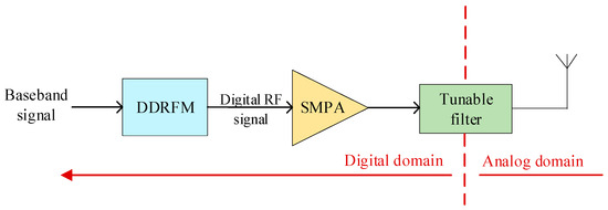
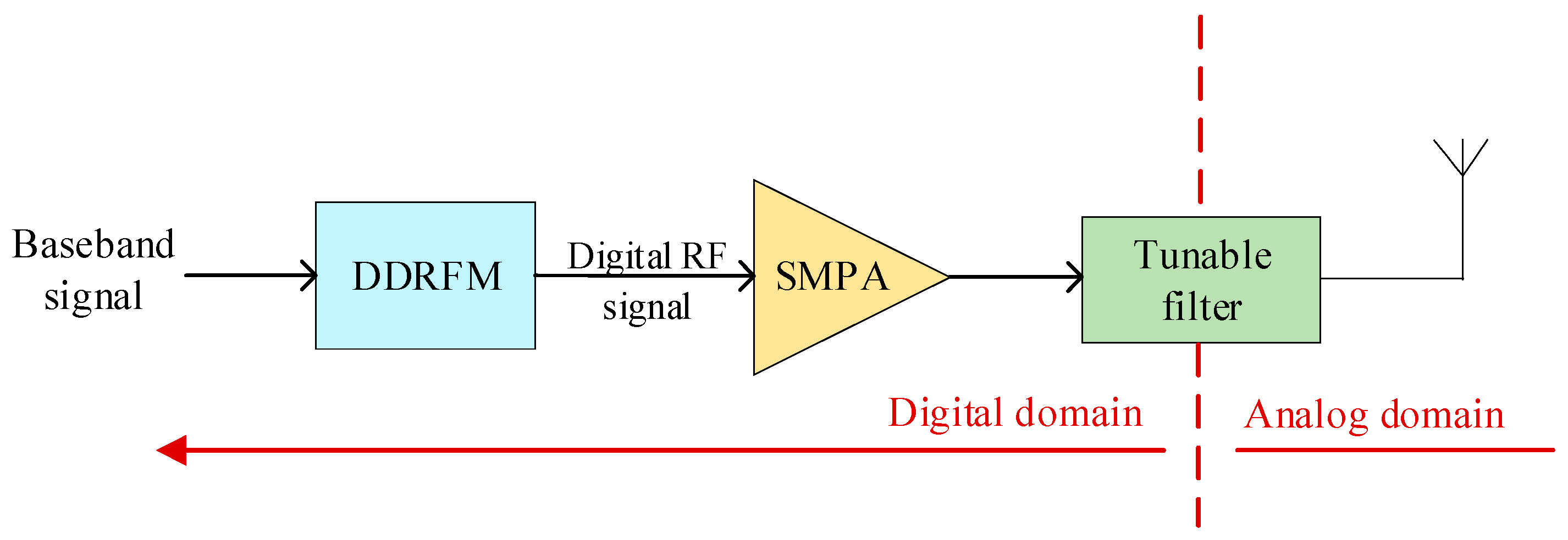
Currently, wireless communication terminals are rapidly advancing toward digitalization, miniaturization, and low power consumption. Simultaneously, they must accommodate an ever-growing array of emerging functions and communication standards, facing heightened demands and challenges in bandwidth, efficiency, and configurability. In traditional analog transmitters, the parameters of analog RF components are fixed, and key performance metrics such as efficiency, linearity, and bandwidth are theoretically mutually constrained [1], limiting improvements in efficiency, size, and reconfigurability. In recent years, advancements in high-speed switching devices have further enhanced the performance of switched-mode power amplifiers, enabling the development of all-digital transmitters (ADTx) [2,3,4,5] and gradually transforming the implementation architecture of traditional analog transmitters. Their flexible reconfigurability, programmability, and comprehensive advantages—including high efficiency and linearity—have become one of the most compelling features for Software-Defined Radio (SDR) [6,7]. As shown in Figure 1, the ADTx primarily consists of a Direct Digital Radio Frequency Modulator (DDRFM) [8], a Switched-Mode Power Amplifier (SMPA) [9], and tuning filters. The DDRFM not only upconverts the baseband signal but also converts it into a pulse sequence suitable for amplification by the SMPA. This sequence consists solely of two or a finite number of discrete quantized levels formed through specific pulse coding. Consequently, the DDRFM directly impacts the efficiency and linearity of the ADTx [10], playing a crucial role within the system.
Figure 1.
Structure diagram of the ADTx system.
Traditional pulse encoding methods include Delta–Sigma Modulation (DSM) [11,12,13] and Pulse-Width Modulation (PWM) [14,15]. To further enhance DDRFM flexibility, mapping-based PWM methods have emerged in recent years, termed Mapping Pulse-Width Modulation (MPWM) [16,17]. Unlike traditional modulation strategies, MPWM directly maps the amplitude and phase of the baseband modulated signal to the pulse width and pulse position of the RF pulse sequence. This achieves a direct mapping between modulation information and the pulse waveform, enabling the convenient, rapid, flexible, and efficient generation of RF pulse signals. In recent years, ref. [18] proposed a hybrid modulation method based on DSM and MPWM. Comprising a DSM module, an MPWM module, and a pulse generator, it directly converts the baseband signal into an RF pulse sequence through mapping, achieving direct correspondence between modulation information and pulse waveforms. This approach significantly reduces the complexity of the digital signal processing system. However, challenges persist in carrier frequency agility. Furthermore, the MPWM in this reference employs only continuous pulses, limiting pulse waveform states and potentially hindering optimal solution acquisition. Consequently, ref. [19] proposed an improved LUT-based IF-MPWM scheme. This approach eliminates the DSM module and implements LUT mapping at the intermediate frequency (IF), enhancing carrier frequency flexibility.
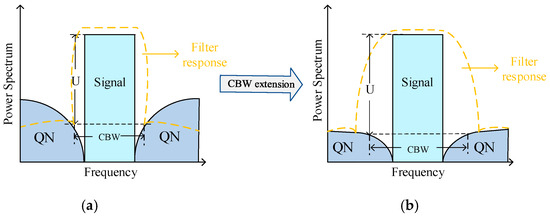
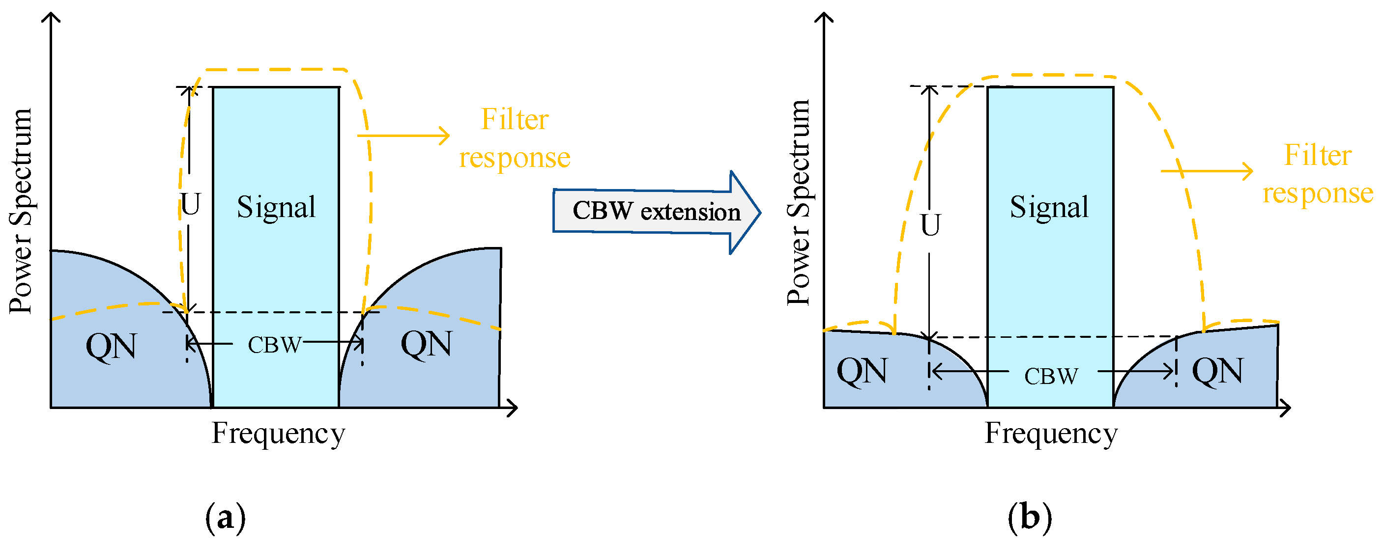
In ADTx, CBW is a critical performance metric for DDRFM. As shown in Figure 2, CBW is defined as the bandwidth below a noise floor of U [20]. According to different application requirements, U has different value requirements. In ADTx, U typically ranges around −40 dB [21]. Usually, the encoding process introduces substantial quantization noise (QN), limiting CBW. This necessitates narrower passbands and higher filter orders in subsequent filter designs, which not only drastically increase the structural complexity and manufacturing cost of the filter hardware but also pose significant technical challenges for the development of downstream filtering modules, such as aggravated insertion loss and compromised signal transmission efficiency in practical applications [22,23].
Figure 2.
(a) Waveform before CBW extension. (b) Waveform after CBW extension.
Different encoding schemes exhibit distinct noise-shaping characteristics, and modifying these inherent characteristics represents a feasible approach to expand the CBW of RF pulse sequences. Figure 2a depicts the signal waveform prior to CBW expansion, while Figure 2b shows the waveform after expansion. Notably, CBW expansion effectively mitigates the design complexity of subsequent filtering modules, which is a critical engineering challenge for ADTx. Building on this principle, ref. [20] proposed an optimized MPWM method to tackle the CBW limitation in LUT-based ADTx architectures, where the RF pulse sequence is optimized to yield the minimum total noise factor as the output [24]. However, this method suffers from high computational complexity, which restricts its practical implementation. To address this issue, ref. [21] extended the CBW by setting two frequency observation points adjacent to the carrier frequency and imposing strict quantization noise constraints at these points as well as the carrier frequency itself.
Based on the foundational work of ref. [21], this paper further extends the CBW of RF pulse sequences in ADTx by adding an additional frequency observation point on each side of the carrier frequency. This enhanced configuration imposes more stringent noise constraints at the expanded set of observation points, thereby optimizing the pulse sequence selection during LUT mapping and achieving a wider CBW. It is worth noting that ref. [21] only adopted two-level pulse sequences, which results in low CE but limits the overall system performance. In contrast, this work employs three-level pulse sequences to improve comprehensive system performance; however, this optimization leads to a substantial increase in the scale of the LUT, which would otherwise slow down the table look-up process. To resolve this trade-off, a partitioned LUT look-up strategy is proposed in this paper. Specifically, during the LUT mapping and query process, the search and traversal operations are confined only to the specific partition that contains the input signal, which drastically reduces the scope of traversal queries and significantly accelerates the look-up efficiency [25].
2. IF-MPWM Architecture to Extend CBW Based on the LUT
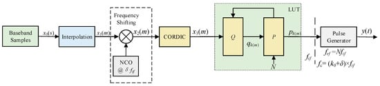
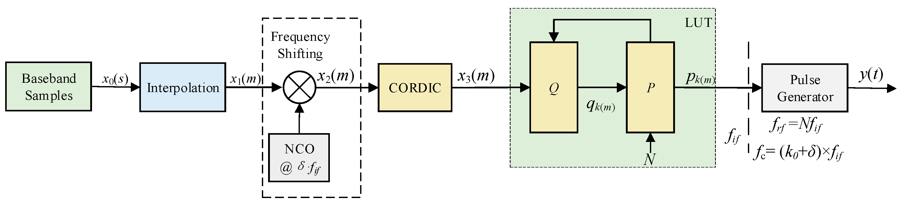
Figure 3 presents the flowchart of the proposed IF-MPWM architecture, which integrates core functional modules including an interpolation module, frequency shifting module, CORDIC (Coordinate Rotation Digital Computer) module, LUT-based quantization mapping module, and pulse generator module [19]. The interpolation module and frequency shifting module are responsible for modulating the signal to the intermediate frequency; the CORDIC algorithm converts the signal from rectangular coordinates to polar coordinates, offering the advantage of reduced computational complexity. The LUT quantization mapper modulates the high-bit-width intermediate-frequency signal into a one-bit radio-frequency output. It first calculates the corresponding LUT address based on the current signal’s amplitude and phase, then maps the signal value to the pulse sequence stored at that LUT address. The pulse generator sequentially concatenates all pulse sequences into the corresponding output pulse signal.
Figure 3.
IF-MPWM implementation block diagram.
As shown in Figure 3, the baseband signal x0(s) undergoes interpolation and frequency shifting module to IF signal x2(m). This IF signal possesses a bandwidth of fBW and a sampling rate of fif. Carrier frequency fc can be expressed as fc = (k0 + δ) × fif, with 0 < δ < 1. Here, k0 and δ denote the integer part and the fractional part of the ratio of the carrier frequency fc to the intermediate sampling frequency fif, where k0 = ⌊fc/fif⌋ and δ= fc%fif. The signal x2(m) is generated by up-converting the interpolated baseband input signal x1(m), where m denotes the discrete time index of the signal sampling sequence. It can be expressed as Equation (1).
Subsequently, the CORDIC module performs a polar coordinate transformation on the signal x2(m). This transformation process is expressed by Equation (2), where ρ(m) and φ(m) denote the amplitude and phase of the IF signal x2(m). Since the distribution of Q on the coordinate axis is approximately circular, characterizing it in polar coordinates is more efficient in saving the space overhead of data storage and representation compared with Cartesian coordinates.
Index the LUT with the amplitude and phase of x3(m) as the address, and map it to a pulse sequence p(n) of length N.
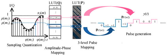
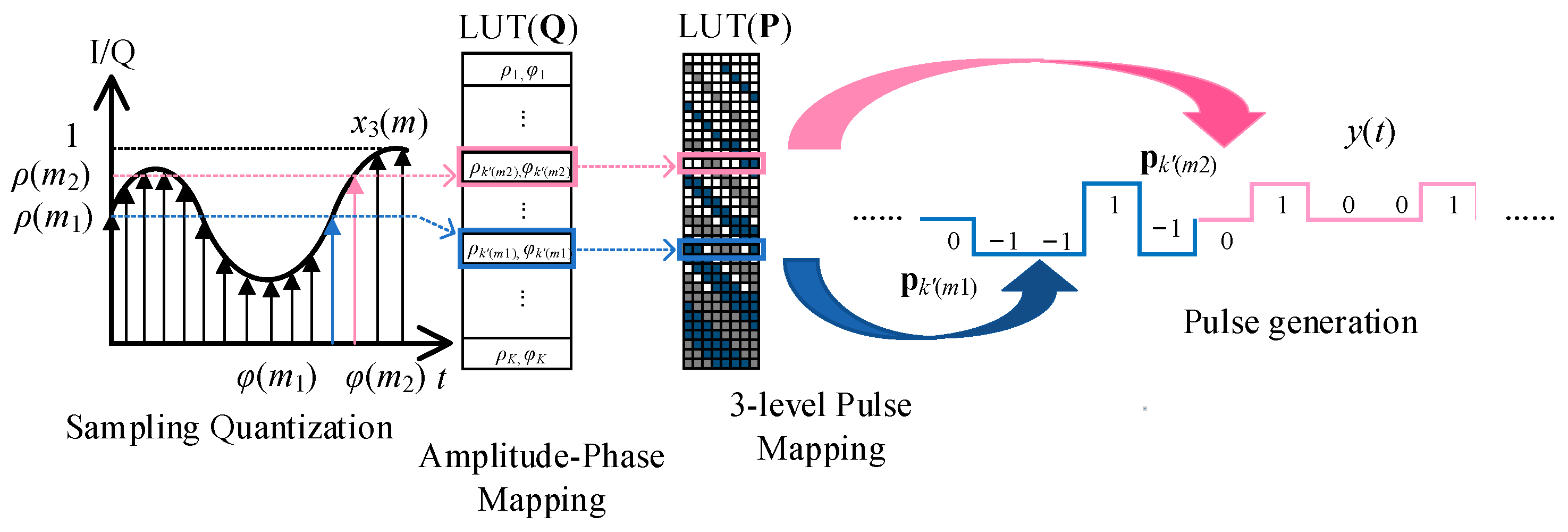
The distinctions between x3(m) and p(n) are enumerated as follows: the carrier frequency of p(n) lies at fc; the carrier frequency of x3(m) resides at δ·fif; the sampling rate of p(n) is N times that of x3(m), which can be expressed as frf = N·fif. The core of MPWM technology resides in the LUT mapping module, as illustrated in Figure 4, which aims to map input modulation information onto output pulse waveforms. The specific implementation method is as follows:
Figure 4.
Flowchart of the three-level pulse width mapping algorithm.
- (1)
- Design two LUTs. Establish two mapping tables: the amplitude–phase mapping table Q and the output pulse sequence table P. Here, P represents the amplitude and phase information corresponding to all elements in P.
- (2)
- Employ a specific look-up strategy for mapping the LUTs. First, perform a mapping look-up in Q to find the optimal mapping point (ρp_k(m), φp_k(m)) for the input point (ρ(m), φ(m)). Subsequently, utilizing the aforementioned one-to-one correspondence between P and Q, the corresponding output pulse sequence pk(m) for (ρp_k(m), φp_k(m)) is retrieved from P.
The process of generating the LUT to extend CBW in [21] is as follows:
- (1)
- The set of all two-level pulse sequences of length N is denoted as P,P = {pk| k = 1,2,…2N}, where pk represents an individual pulse sequence. The values of qk,0, qk,1, and qk,2 are then calculated according to Equation (4). We define the sets containing all qk,0, qk,1, and qk,2 values as Q0 = {qk,0| k = 1,2,…2N}, Q1 = {qk,1| k = 1,2,…2N}, and Q2 = {qk,2| k = 1,2,…2N}, respectively. Among them, fCBW is the set CBW.
- (2)
- Find a pulse sequence pk for the amplitude ρ(m) and phase φ(m) of any set of possible IF signals x2(m), such that it satisfies Equation (5), where ε is the value that limits the error, and r represents the amplitude correction value for mapping inputs and outputs:
Record all pulse sequences pk and qk,1, qk,2 (k ∈ Kρ,φ) that satisfy Equation (5) and their corresponding sets. The sets are Pρ,φ, Q1ρ,φ, and Q2ρ,φ.
- (3)
- Define the bi-objective function as follows:
The pulse sequence corresponding to any set of (ρ(m), φ(m)) in LUT is as follows:
- (4)
- Save the pk(ρ,φ) value in the corresponding address of set (ρ(m), φ(m)) in LUT.
Finally, the pulse generator serially concatenates all pk(ρ,φ) sequences corresponding to the input modulated signals into the final output three-level RF pulse signal y(t).
3. Optimization Algorithm Based on IF-MPWM for CBW Extension
3.1. CBW Extension of IF-MPWM Encoding Method
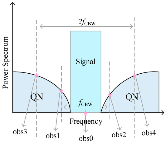
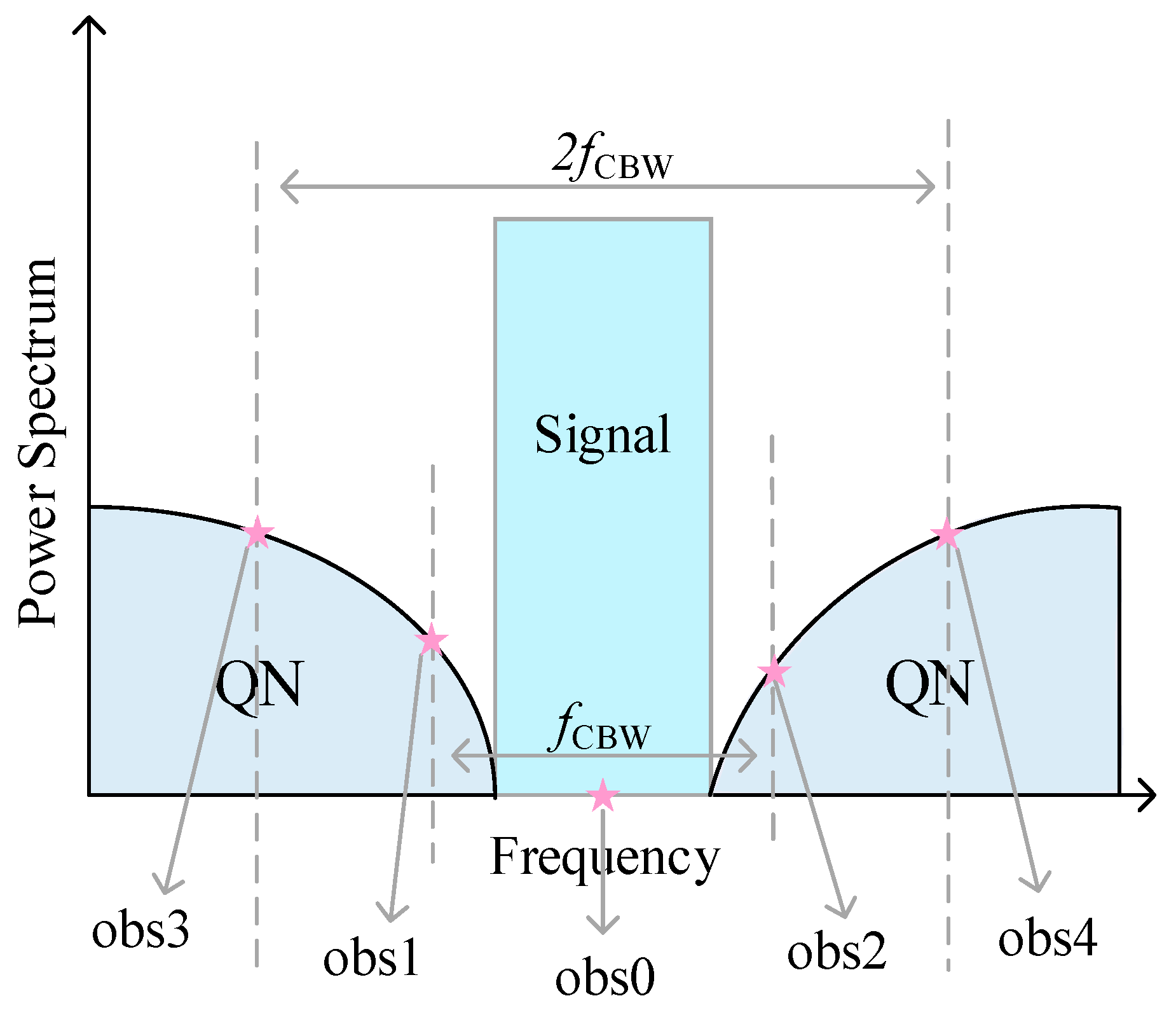
In order to further expand the CBW, the following algorithm is proposed. As shown in Figure 5, by setting four observation points on the left and right sides of the carrier frequency, such as obs0, obs1, obs2, obs3, and obs4, and limiting the noise power at the observation points and the carrier frequency, the noise-shaping characteristics of the output spectrum are changed to achieve the purpose of expanding CBW.
Figure 5.
Schematic diagram of frequency observation points.
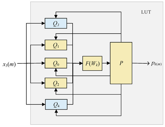
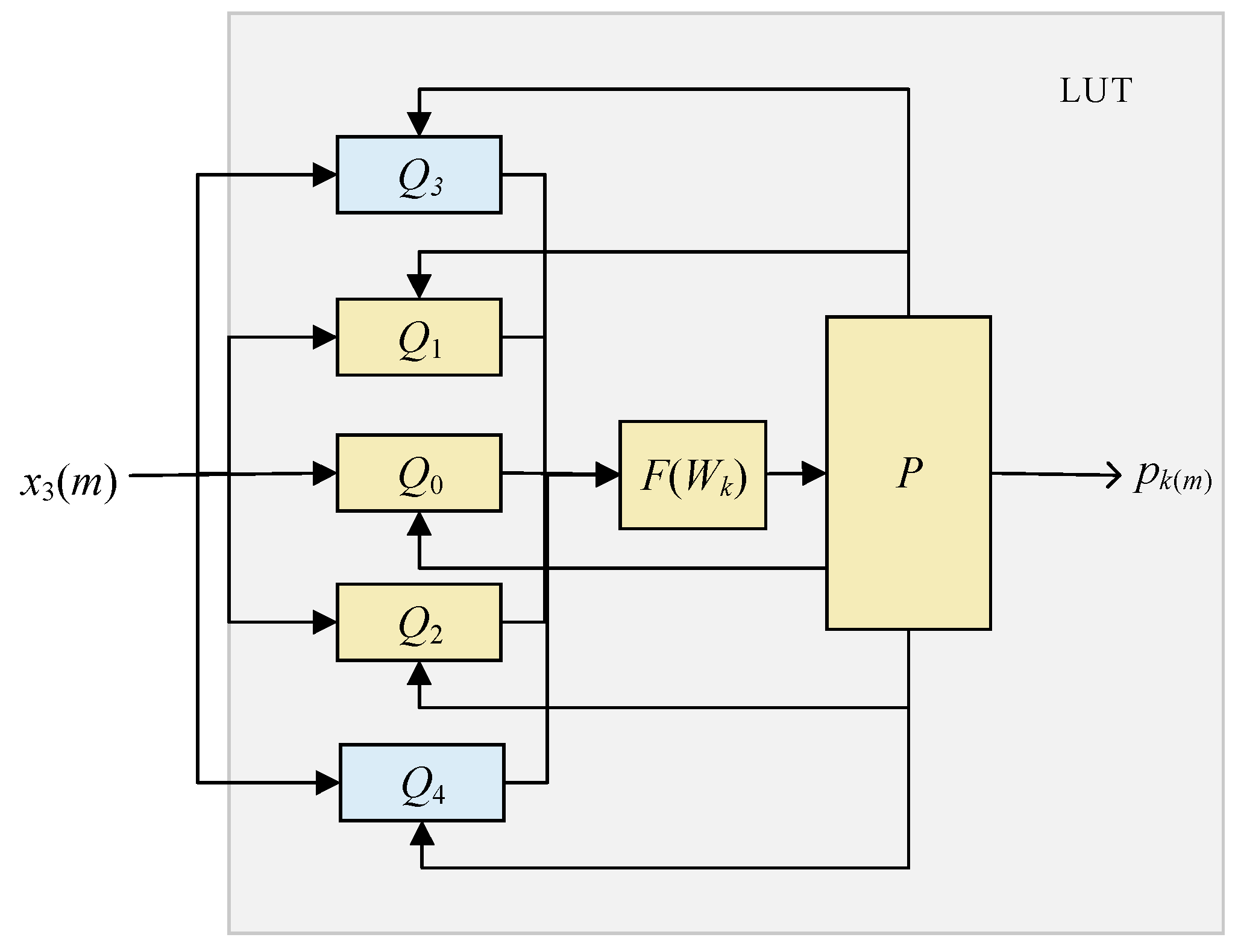
The LUT-specific mapping process is shown in Figure 6. Compared with references [21], two points of obs3 and obs4 are added in this algorithm. Q3 and Q4 are added to further limit observation points’ noise during MPWM. The process of creating the LUT is as follows:
Figure 6.
LUT-specific mapping process.
The construction process of the LUT is elaborated as follows:
- (1)
- Firstly, generate Q0 to Q4 according to obs0, obs1, obs2, obs3, and obs4. The set composed of all three-level pulse sequences with a length of N is denoted as P,P = {pk| k = 1,2,…3N}, and each pulse sequence is pk. Then, calculate the values of qk,0, qk,1, qk,2, qk,3, and qk,4 according to Equation (9), and denote them separately as Q0, Q1, Q2, Q3, and Q4.
- (2)
- Secondly, calculate the average noise power of the observation points Wλ.
- (3)
- Furthermore, look for qk(m) according to Equation (12). In Equation (11), a is the weight coefficient, which is used to balance the optimization priority of in-band noise and observation-point noise.
- (4)
- Subsequently, save the pk(m) according to qk(m) in the corresponding address of set (ρ(m), φ(m)) in LUT.
Finally, the pulse generator serially concatenates all pk(ρ,φ) sequences corresponding to the input modulated signals into the final output three-level RF pulse signal y(t).
3.2. Mapping Look-Up Strategy
In practical applications, the mapping look-up process typically employs an exhaustive search strategy. This involves calculating the error between the input amplitude–phase information (ρ(m), φ(m)) and all (ρp_i, φp_i) in Q, then comparing to obtain the minimum error εk. Each look-up requires M computations and M − 1 comparisons, where M = LN. Specifically, M refers to the total number of calculations, N represents the length of the pulse sequence, and L stands for the number of levels. While the exhaustive search method guarantees retrieval of the optimal mapping qk within Q, the extensive computational comparison process significantly increases the real-time performance of MPWM. As pulse sequence length N and the level number L increase, the corresponding M value grows, prolonging the mapping look-up time and imposing higher demands on the computational capabilities of digital processing devices.
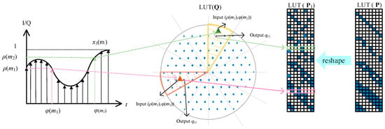
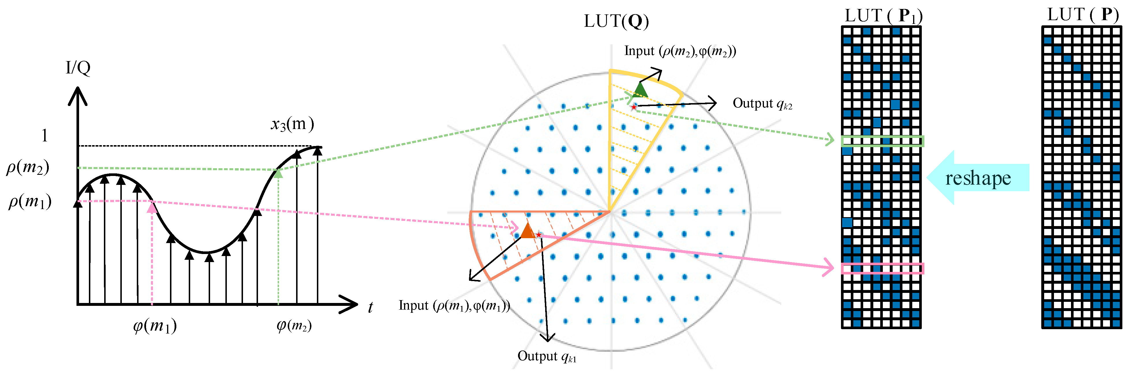
However, the size of LUT Q in the above algorithm is five times larger, which not only elevates the total number of calculations considerably but also results in slower traversal speed in a progressive manner. In response to this series of problems, a partition query strategy is proposed. The mapping flow chart is shown in Figure 7. The colored triangle represents the mapping input point, and the star represents the mapping output point.
Figure 7.
Partition query strategy schematic.
Firstly, P is reconstructed according to the phase value to obtain P1. All amplitude–phase information corresponding to possible pulse sequences is divided into N zones based on phase. Subsequently, the phase of the modulated input signal serves as an index to locate the partition corresponding to that phase. Within this partition, the input signal is mapped to Q. This approach substantially reduces the scale of traversal queries and improves the real-time performance of MPWM.
4. Simulation and Analysis
To validate the proposed optimization algorithm and partitioned search strategy, this section first conducts optimization simulations for the noise power weighting coefficient a in Equation (11). Subsequently, optimization simulations are performed for the amplitude correction value r in Equation (10). Finally, the algorithm in this paper is compared with the SI algorithm from [19] and the SII algorithm from [21], confirming the effectiveness of this proposed approach.
4.1. Optimization of Noise Power Weighting in Objective Function
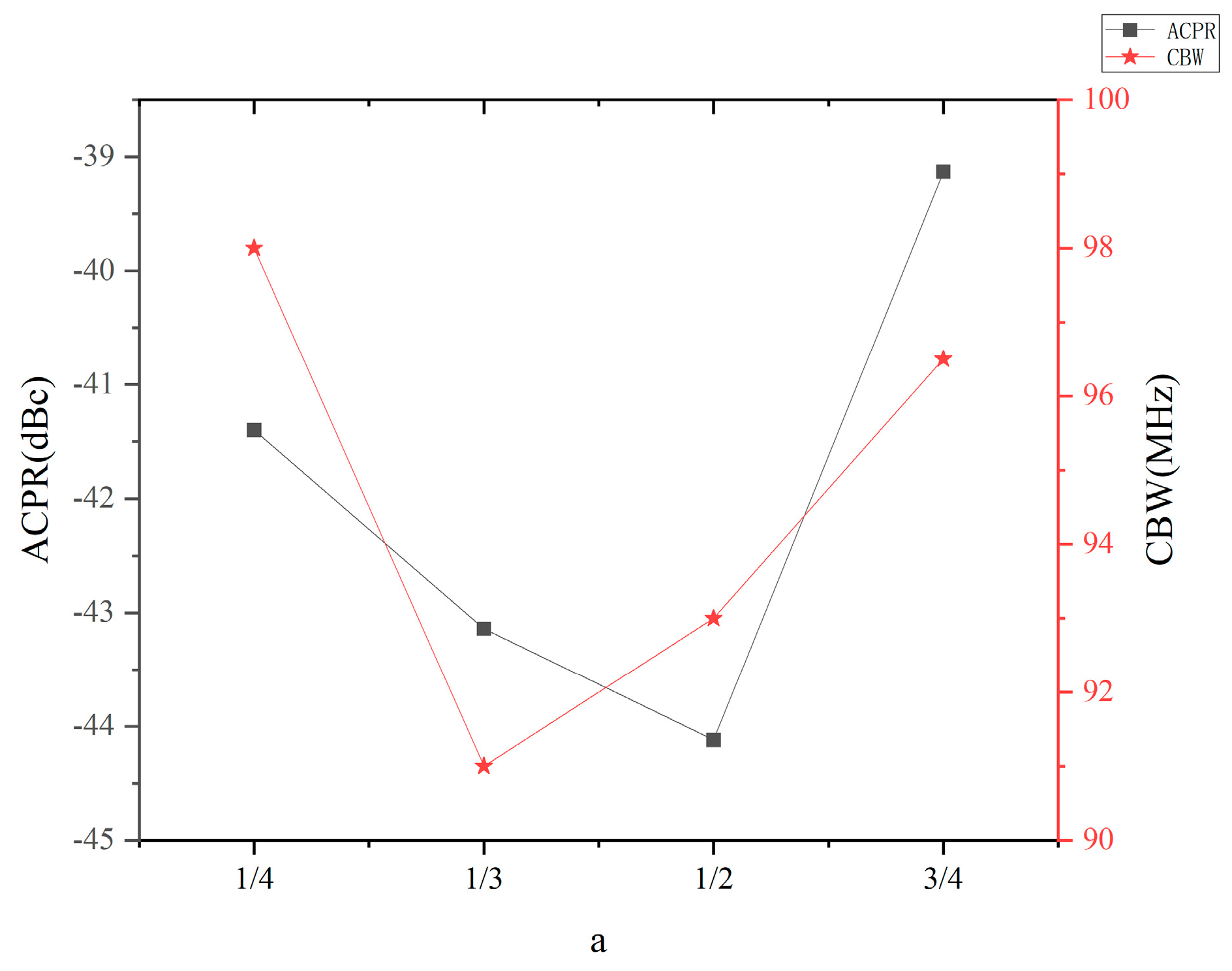
The proposed algorithm optimizes the weighting of noise power across different frequency observation points when selecting the objective function. Table 1 below compares the system performance metrics at different a. It is evident that variations in a are insensitive to CE and Pt, where Pt denotes the fundamental power of the output signal, but significantly impact ACPR and CBW.
Table 1.
Comparison of system performance indexes at different a.
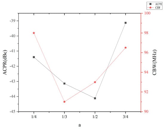
Figure 8 illustrates the trends of ACPR and CBW as a varies. It can be seen that ACPR has the best performance when a = 1/2. At the same time, CBW performance is equivalent.
Figure 8.
Performance comparison of output signals at different a.
4.2. MPWM Input–Output Mapping MATCHING Optimization
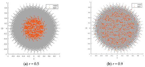
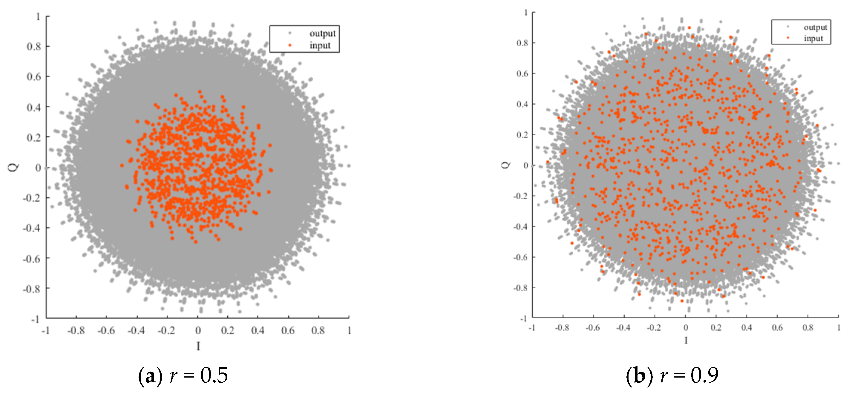
The parameter r is an amplitude scaling factor used to adjust the amplitude distribution of the input signal to better match the amplitude range of the output points in the look-up table Q. Within the mapping space of Q, a mapping matching issue exists between inputs and outputs. Should the range of mapping input points far exceed that of mapping output points, input points lying outside the mapping output points inevitably face substantial mapping errors. Conversely, should the range of mapping input points be significantly smaller than Q’s space, the utilization rate of Q’s mapping space becomes excessively low, resulting in a low CE for the modulation scheme. Therefore, by optimizing the configuration of relevant parameters influencing the distribution of mapping inputs and outputs, the mapping input points and output points of Q are made to align as closely as possible within the mapping space.
As illustrated in Figure 9, the plot depicts the variation in the distribution of input signals and elements within the Q matrix for different values of the parameter r. It is evident that r exerts a significant influence on the positional distribution of input signals and acts as a critical parameter governing the amplitude distribution of input signals. When r takes a small value, the overall amplitude of the input signal is reduced, which leads to a general decrease in the magnitude of the output points selected via LUT mapping. This consequently results in low useful signal power and poor CE performance. In contrast, a large value of r enables the input signal to be mapped to output signals with a larger amplitude, thereby improving the CE performance. However, this improvement is accompanied by an increased mapping error and degraded modulation linearity.
Figure 9.
Different distributions of the input signal with Q for different r.
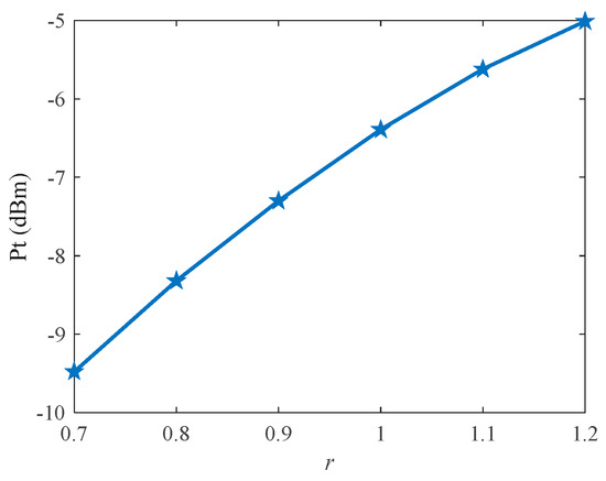
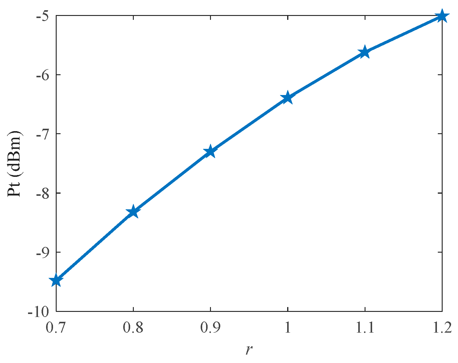
Figure 10 depicts the effect of parameter r on fundamental power, which serves as a measure of the signal’s effective component and directly determines the system’s transmission quality and efficiency. Greater fundamental power enables longer transmission distances and stronger interference resistance.
Figure 10.
The influence of r on fundamental wave power.
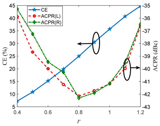
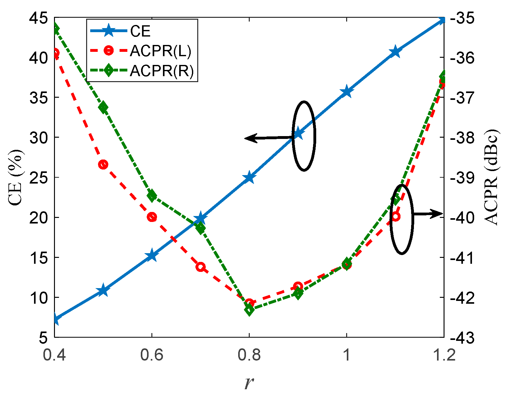
Figure 11 depicts the influence of parameter r on CE and ACPR. Specifically, CE exhibits a positive correlation with r. However, this correlation does not indicate that larger values of r will yield better overall system performance. As r increases, the ACPR of the signal first reaches an optimal value before deteriorating rapidly, which is accompanied by a sharp increase in noise levels in the vicinity of the carrier frequency. When r = 0.8, the system achieves better linear performance, but at the cost of poorer CE. In contrast, when r = 1, the system exhibits improved CE performance, while its linearity is compromised. Therefore, the appropriate value of r must be selected based on specific application scenarios. Based on comprehensive simulation analyses and parameter comparisons, to maximize CE performance while ensuring satisfactory linearity, the mapping parameter in this work is set to r = 0.9.
Figure 11.
CE and ACPR of the output pulse sequence under different r.
4.3. Simulation Comparison of Different Modulation Schemes
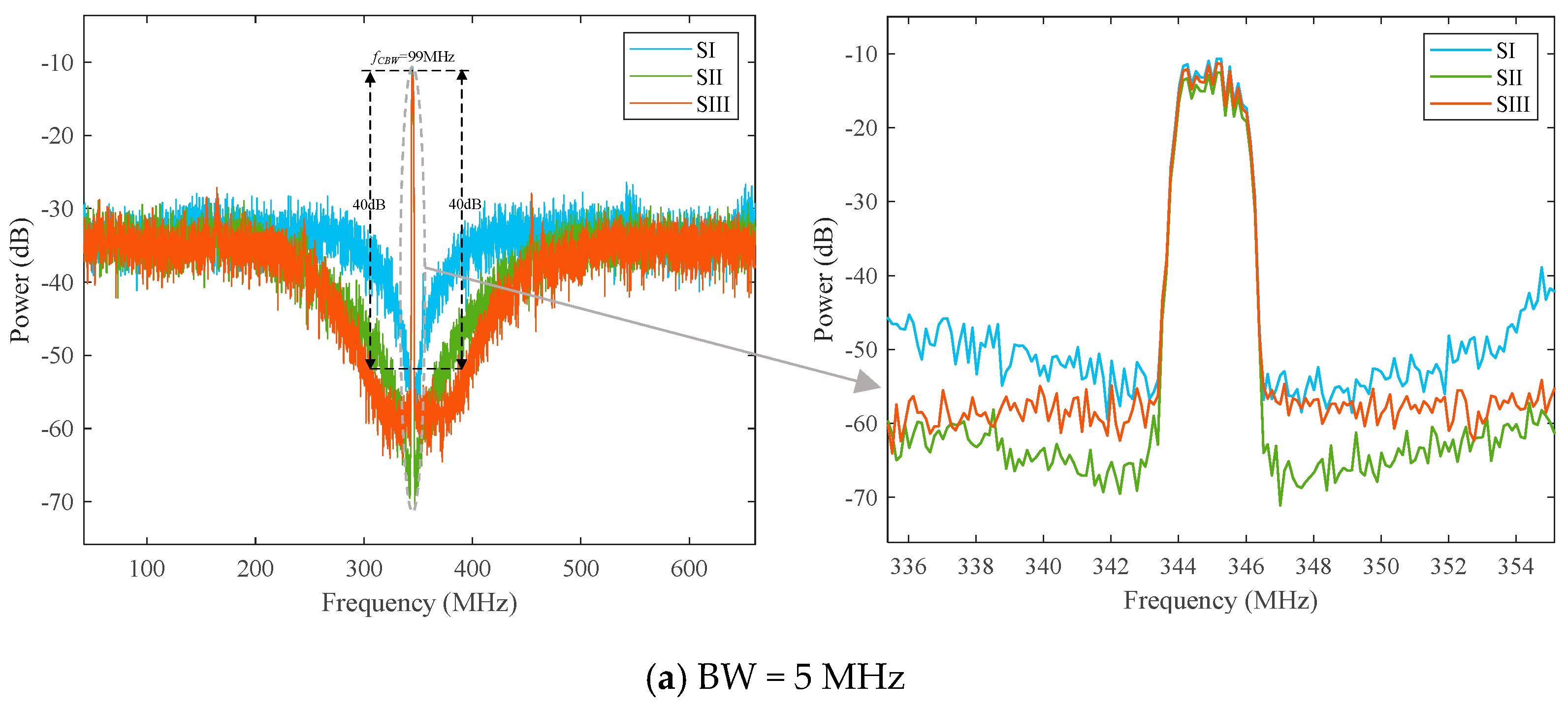
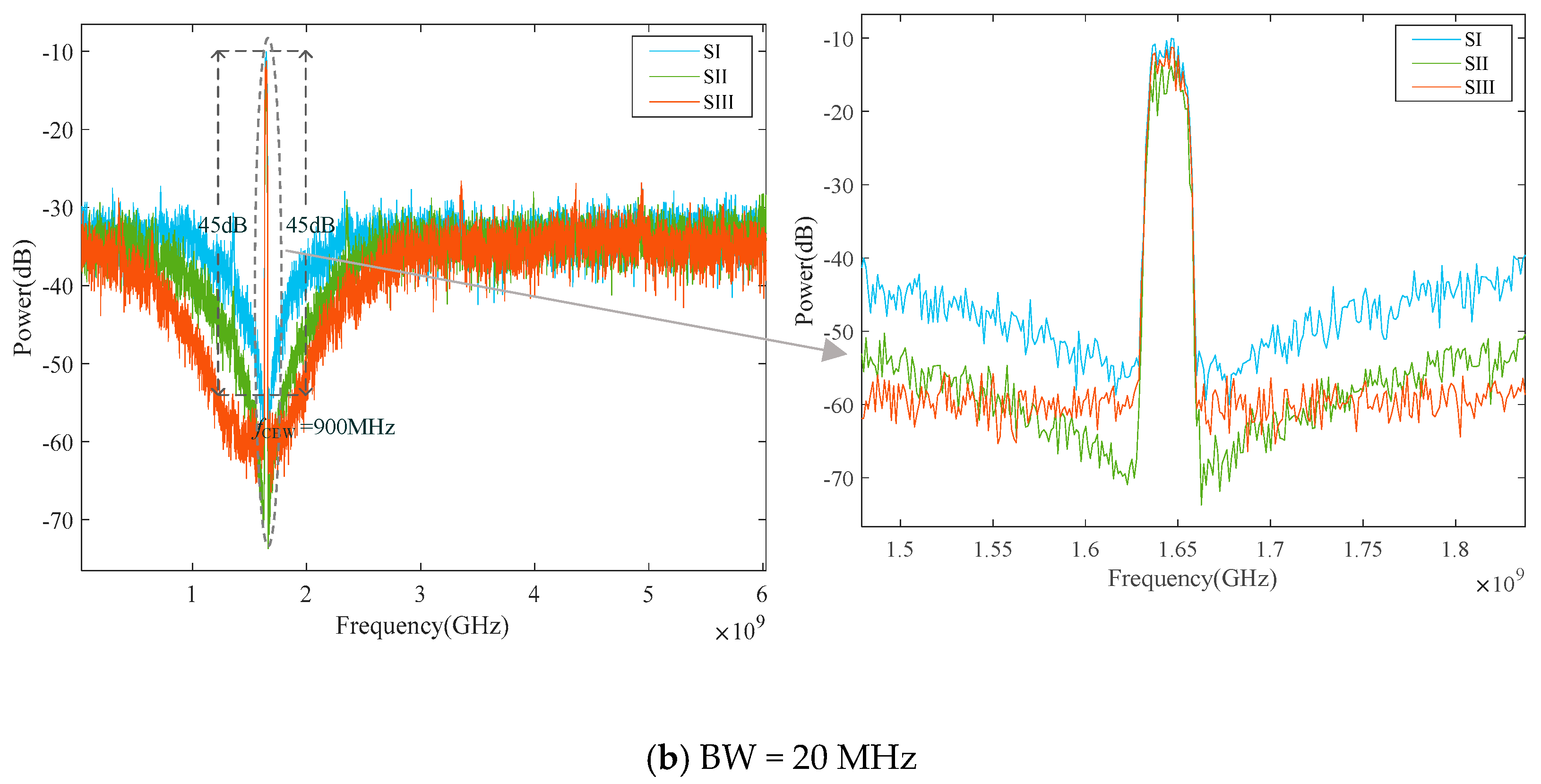
To validate the clean bandwidth expansion method proposed above, simulation experiments were conducted using MATLAB R2023b simulation software to compare the algorithm SI from ref. [19], the strategy SII from ref. [21], and the optimized algorithm SIII proposed herein. Table 2 lists the simulation parameters.
Table 2.
Simulation parameters.
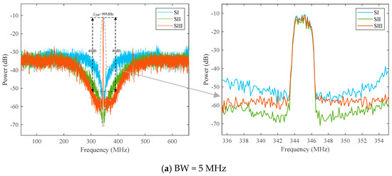
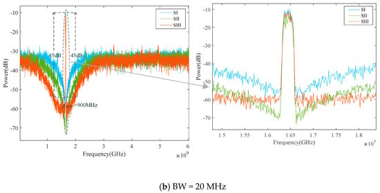
Figure 12 illustrates the spectral comparison of SIII with SI and SII under different bandwidths. It is evident that the proposed algorithm achieves a significant expansion of the clean bandwidth compared to SI and SII, while simultaneously reducing filter loss and enhancing system efficiency.
Figure 12.
Spectrogram comparison of algorithm SI with SII and SIII under different bandwidths.
Table 3 presents the specific performance metrics for three distinct CBW extension algorithms. The proposed optimized CBW algorithm demonstrates significant improvements over both SII and the approach described in [20]. Crucially, it achieves a CE exceeding 30% without noticeable deterioration in linear metrics, substantially outperforming both SI and SII. This validates the effectiveness and innovative nature of this modulation scheme.
Table 3.
Comparison of different algorithms.
To validate the efficiency of the partitioned look-up strategy, simulations were conducted under identical parameters to compare it with the exhaustive search approach. Table 4 presents the key modulation performance metrics and look-up process comparisons for both schemes. Both approaches exhibit fundamentally identical performance metrics, indicating that the partitioned look-up strategy produces virtually identical mapping outputs to the mapping look-up strategy. However, it substantially reduces the scale and duration of exhaustive queries, thereby validating the strategy’s efficiency.
Table 4.
Look-up strategy comparison.
5. Conclusions
In this paper, an optimization algorithm based on IF-MPWM is proposed to solve the problem of limited CBW of RF pulse sequence in ADTx. The ADTx is limited by quantization noise and in-band noise, resulting in a narrow CBW, which increases the difficulty of filter design and reduces the system efficiency. Therefore, the proposed algorithm sets observation points near the carrier frequency and extends the CBW by minimizing the weighted power of multiple observation points to suppress noise in a wider frequency domain. However, as observation points are added, the size of Q increases dramatically, and the search process is slow. In addition, this article uses a three-level system for better system performance. Concurrently, this approach leads to a significant increase in the size of the look-up table. Therefore, a partition look-up strategy is proposed to greatly reduce the scale of calculation and query.
Simulation results validate that the proposed scheme outperforms the SII method in CBW expansion, with significantly improved CE. Notably, the selection of an optimal parameter r is a key design consideration that enables a trade-off between CBW extension and signal quality to meet specific system requirements.
Future research will focus on the optimization of LUT construction, with the core objective of further reducing the table scale and lowering the storage overhead of the system.
Author Contributions
Conceptualization, Y.L. and Q.Z.; methodology, Y.L. and Q.Z.; software, Y.L. and Q.Z.; validation, Y.L.; formal analysis, Y.L., Q.Z. and L.Z.; investigation, Y.L., J.Y. and H.F.; resources, Q.Z.; data curation, Y.L.; writing—original draft preparation, Y.L.; writing—review and editing, Y.L. and Q.Z.; visualization, Y.L.; supervision, Q.Z. and Y.L.; project administration, Q.Z. and Y.L.; funding acquisition, Q.Z. All authors have read and agreed to the published version of the manuscript.
Funding
This research received no external funding.
Data Availability Statement
The raw data supporting the conclusions of this article will be made available by the authors on request.
Conflicts of Interest
The authors declare no conflicts of interest.
References
- Lavrador, P.M.; Cunha, T.R.; Cabral, P.M.; Pedro, J. The Linearity-Efficiency Compromise. IEEE Microw. Mag. 2010, 11, 44–58. [Google Scholar] [CrossRef] [Scilit]
- Morales, J.I.; Chierchie, F.; Mandolesi, P.S.; Paolini, E.E. A Distortion-Free All-Digital Transmitter Based on Noise-Shaped PWM. IEEE Trans. Circuits Syst. I Regul. Pap. 2023, 70, 694–704. [Google Scholar] [CrossRef] [Scilit]
- Yao, F. Core technologies of digital radio frequency for advanced radio platform and their engineering practice. Sci. Sin. (Informationis) 2014, 44, 965–979. (In Chinese) [Google Scholar] [CrossRef] [Scilit]
- Yin, L.; Liu, D.; Bai, Y. Jitter enhanced full digital RF transmitter and PWM RFPA for 5G broadband communications. China Commun. 2022, 19, 69–86. [Google Scholar] [CrossRef] [Scilit]
- Lei, Z.; Qiang, Z.; Zhihu, W.; Zhang, C.; Jibo, W.; Jianbin, C.; Zhiyuan, Z. A novel all digital transmitter with three-level quadrature differential RF-PWM. J. Phys. Conf. Ser. 2021, 1827, 012032. [Google Scholar] [CrossRef] [Scilit]
- Mitola, J. The software radio architecture. IEEE Commun. Mag. 1995, 33, 26–38. [Google Scholar] [CrossRef] [Scilit]
- Ghannouchi, F.M. Power amplifier and transmitter architectures for software defined radio systems. IEEE Circuits Syst. Mag. 2010, 10, 56–63. [Google Scholar] [CrossRef] [Scilit]
- Chen, J.; Zhang, J.; Zhou, Q.; Zhihu, W. Pulse encoding strategy using 3-level non-uniform quantizing. J. Natl. Univ. Def. Technol. 2020, 42, 137–143. (In Chinese) [Google Scholar] [CrossRef]
- Bieg, R.; Grozing, M.; Schmidt, M.; Berroth, M. Switching Mode Power Amplifier Concept Combining Multi-Level and Pulse-Width Modulation. In Proceedings of the 2020 German Microwave Conference, Cottbus, Germany, 9–11 March 2020; IEEE: Piscataway, NJ, USA, 2020; pp. 264–267. [Google Scholar]
- Silva, N.V.; Oliveira, A.S.R.; Carvalho, N.B. Design and Optimization of Flexible and Coding Efficient All-Digital RF Transmitters. IEEE Trans. Microw. Theory Tech. 2013, 61, 625–632. [Google Scholar] [CrossRef]
- Choi, J.; Yim, J.; Yang, J.; Kim, J.; Cha, J.; Kang, D.; Kim, D.; Kim, B. A ΔΣ-Digitized Polar RF Transmitter. IEEE Trans. Microw. Theory Tech. 2007, 55, 2679–2690. [Google Scholar] [CrossRef]
- Marin, R.-C.; Frappé, A.; Kaiser, A. Digital Complex Delta–Sigma Modulators with Highly Configurable Notches for Multi-Standard Coexistence in Wireless Transmitters. IEEE Trans. Circuits Syst. I Regul. Pap. 2018, 65, 343–352. [Google Scholar] [CrossRef] [Scilit]
- Nuyts, P.A.J.; Reynaert, P.; Dehaene, W. A fully digital PWM-based 1 to 3 GHz multistandard transmitter in 40-nm CMOS. In Proceedings of the 2013 IEEE Radio Frequency Integrated Circuits Symposium (RFIC), Seattle, WA, USA, 2–4 June 2013; IEEE: Piscataway, NJ, USA, 2013; pp. 419–422. [Google Scholar] [CrossRef] [Scilit]
- Hezar, R.; Ding, L.; Banerjee, A.; Hur, J.; Haroun, B. A PWM Based Fully Integrated Digital Transmitter/PA for WLAN and LTE Applications. IEEE J. Solid-State Circuits 2015, 50, 1117–1125. [Google Scholar] [CrossRef] [Scilit]
- Chen, J.; Zhou, Q.; Zhu, L.; Jiang, Z. A selective harmonic elimination RF-PWM and performance analysis. J. Natl. Univ. Def. Technol. 2021, 43, 128–135. [Google Scholar] [CrossRef]
- Raab, F. Radio Frequency Pulsewidth Modulation. IEEE Trans. Commun. 1973, 21, 958–966. [Google Scholar] [CrossRef] [Scilit]
- Markert, D.; Yu, X.; Heimpel, H.; Fischer, G. An All-Digital, Single-Bit RF Transmitter for Massive MIMO. IEEE Trans. Circuits Syst. I Regul. Pap. 2017, 64, 696–704. [Google Scholar] [CrossRef] [Scilit]
- Keyzer, J.; Uang, R.; Sugiyama, Y.; Iwamoto, M.; Galton, I.; Asbeck, P.M. Generation of RF pulsewidth modulated microwave signals using delta-sigma modulation. In Proceedings of the 2002 IEEE MTT-S International Microwave Symposium Digest (Cat. No.02CH37278), Seattle, WA, USA, 2–7 June 2002; IEEE: Piscataway, NJ, USA, 2002; Volume 1, pp. 397–400. [Google Scholar] [CrossRef] [Scilit]
- Yang, J.; Yang, S.Y.; Chen, Z.H.; Zhang, X.Y. An Agile LUT-Based All-Digital Transmitter. IEEE Trans. Circuits Syst. I Regul. Pap. 2020, 67, 5550–5560. [Google Scholar] [CrossRef] [Scilit]
- Yang, S.Y.; Yang, J.; Zhao, J.; Zhang, X.Y. Clean Bandwidth Improvement of MPWM Encoding Method for RF All-Digital Transmitter. IEEE Trans. Circuits Syst. II Express Briefs 2021, 68, 2404–2408. [Google Scholar] [CrossRef] [Scilit]
- Zhu, L.; Wei, Z.; Chen, Z.; Zhou, Q.; Zhao, H.; Wei, J. A Bi-objective Optimization Algorithm to extend the Clean Bandwidth of All Digital Transmitters. In Proceedings of the 2024 IEEE 24th International Conference on Communication Technology (ICCT), Chengdu, China, 18–20 October 2024; IEEE: Piscataway, NJ, USA, 2024; pp. 992–996. [Google Scholar] [CrossRef] [Scilit]
- Shu, X. Design of Direct Digital Radio Frequency Modulator. Master’s Thesis, University of Electronic Science and Technology, Chengdu, China, 2021. (In Chinese) [Google Scholar]
- Chi, S.; Singerl, P.; Vogel, C. Coding efficiency optimization for multilevel PWM based switched-mode RF transmitters. In Proceedings of the 2011 IEEE 54th International Midwest Symposium on Circuits and Systems (MWSCAS), Seoul, Republic of Korea, 7–10 August 2011; IEEE: Piscataway, NJ, USA, 2011; pp. 1–4. [Google Scholar] [CrossRef] [Scilit]
- Yao, F.; Zhou, Q.; Wei, Z. A Novel Multilevel RF-PWM Method With Active-Harmonic Elimination for All-Digital Transmitters. IEEE Trans. Microw. Theory Tech. 2018, 66, 3360–3373. [Google Scholar] [CrossRef]
- Lu, X.-Z.; Yang, J.; Zhu, H.-R.; Liang, L.-Y. A Method to Halve the LUT Size for MPWM-based All Digital Transmitters. In Proceedings of the 2024 IEEE MTT-S International Wireless Symposium (IWS), Beijing, China, 16–19 May 2024; IEEE: Piscataway, NJ, USA, 2024; pp. 1–3. [Google Scholar] [CrossRef] [Scilit]

Disclaimer/Publisher’s Note: The statements, opinions and data contained in all publications are solely those of the individual author(s) and contributor(s) and not of MDPI and/or the editor(s). MDPI and/or the editor(s) disclaim responsibility for any injury to people or property resulting from any ideas, methods, instructions or products referred to in the content. |
© 2026 by the authors. Licensee MDPI, Basel, Switzerland. This article is an open access article distributed under the terms and conditions of the Creative Commons Attribution (CC BY) license.