


Abstract
This architecture and position paper examines how complex technical systems combine distributed sensing, embedded intelligence, prognostics and health management, and digital-twin services, but these capabilities are often implemented as separate functions. This paper proposes a distributed embedded intelligence (DEI) framework that coordinates diagnostic responsibility across five hierarchical levels, from smart sensing to system-level health management and lifecycle services. Diagnostic functions are assigned according to a lowest-feasible-intelligence-level principle that accounts for data availability, context, timing, computational resources, model validity, connectivity, and authority. Local and fused health states retain fault hypotheses, functional capacity, uncertainty, confidence, and provenance, while hierarchical fusion and event-driven escalation determine whether an event can be resolved locally, requires additional evidence, or must be transferred to a higher level. Digital-twin and fleet services provide prognosis, scenario analysis, maintenance planning, and controlled model support without replacing essential real-time diagnosis. The framework is illustrated through progressive degradation of an aircraft hydraulic pump and an architecture-level comparison of centralized, edge-assisted, and DEI configurations. An illustrative calculation using assumed message sizes, event rates, and execution times suggests potential reductions in communication demand and detection-and-confirmation latency; preservation of lower-level capability during loss of higher-level services is a design objective. The study provides an architectural template proposed for adaptation to other systems for resilient distributed health management; the quantitative results are conditional architectural estimates, without experimental validation or demonstrated aircraft performance.
1. Introduction
1.1. Background and Motivation
This is an architecture and position paper. Its main contribution is the integration of established embedded and edge processing, distributed diagnosis, hierarchical health management, uncertainty handling, and digital-twin support into one governed architecture. The allocation formulation and reference fusion module make selected design rules explicit. The aircraft example illustrates their organization and conditional costs; it does not provide a complete implemented or experimentally validated health-management system.
The increasing complexity, connectivity, and functional interdependence of modern technical systems have changed the role of condition monitoring. Conventional architectures primarily collect measurements and transfer them to centralized platforms for analysis. Prognostics and health management (PHM) extends this approach by combining condition assessment, fault diagnosis, degradation prediction, and maintenance decision support [1,2,3]. In aerospace applications, Integrated Vehicle Health Management and Integrated System Health Management further relate component and subsystem condition to aircraft availability, mission capability, and maintenance requirements [4,5].
Artificial intelligence and deep learning have substantially improved feature extraction, fault classification, and remaining-useful-life estimation from heterogeneous monitoring data [6,7,8]. However, advances in diagnostic algorithms do not by themselves resolve the architectural question of where diagnostic functions should be executed. Centralized processing offers broad context and computational capacity but may increase communication demand and latency and concentrates diagnostic capability in relatively few processing nodes.
Embedded and edge intelligence provide a complementary approach by moving selected analytical functions closer to the monitored process. Lightweight AI models, hardware-aware implementations, and distributed inference enable local processing under constrained computation, memory, and energy resources [9,10,11,12]. High-rate measurements can therefore be converted near the source into features, anomaly indicators, or compact health information. Yet computational placement alone does not define how diagnostic responsibility, uncertainty, functional capacity, decision authority, and cooperation among distributed nodes should be organized.
This study addresses this architectural gap through the concept of distributed embedded intelligence (DEI). DEI coordinates monitoring, diagnostic, and decision-support functions across smart sensors, component nodes, subsystem agents, system-level health management, and lifecycle services. Its objective is not maximal decentralization, but deliberate allocation of each function to the lowest hierarchical level that has sufficient data, context, resources, validated competence, connectivity, and authority. Higher levels progressively add broader functional and operational context, while uncertain, conflicting, or safety-relevant conditions can be transferred through controlled event-driven escalation.
1.2. Related Work
Research relevant to distributed embedded intelligence spans several established but only partially integrated domains. Figure 1 summarizes five principal directions (items 1.1–1.5): embedded and edge intelligence, distributed fault diagnosis, hierarchical health monitoring, digital twins and PHM, and aircraft health-management systems. Their intersection defines the research context for the proposed framework.
Figure 1.
Research landscape and gap. The sources corresponding to each research direction and literature contribution are cited in Section 1.2.
The PHM literature covers PHM, condition-based maintenance, and intelligent fault diagnosis. Established reviews describe the progression from signal processing and feature engineering towards data-driven fault classification, prognosis, and remaining-useful-life estimation [1,2,3,6,7,8]. In aerospace applications, integrated vehicle health management (IVHM) and integrated system health management (ISHM) extend health monitoring from component-level condition assessment to system-level availability, mission capability, and maintenance support [4,5]. These approaches provide mature diagnostic and prognostic methods but do not by themselves determine how diagnostic responsibility should be distributed across multiple computational and hierarchical levels.
Another related direction is embedded and edge intelligence. Local inference, lightweight AI, hardware-aware implementation, and distributed neural-network execution reduce dependence on central or cloud resources and enable processing close to the data source [9,10,11,12]. However, this literature primarily addresses computational placement and resource efficiency rather than the coordinated allocation of diagnostic responsibility, authority, and system-level health reasoning.
Distributed fault-diagnosis methods constitute a related direction. Observer-based and data-driven approaches distribute fault detection and isolation among interconnected subsystems and demonstrate the benefits of cooperation among local diagnostic agents [13,14,15]. Their formulations are typically application- or algorithm-specific and do not generally extend from sensor-level assessment through subsystem fusion to system consequence and lifecycle reasoning.
A further direction is hierarchical health monitoring. Earlier work organized condition or damage assessment across sensor, component, and structural levels [16], while more recent studies combine hierarchical monitoring with embedded or TinyML-compatible implementation [17]. Such architectures reflect the physical decomposition of complex assets, but usually provide limited treatment of explicit diagnostic authority, uncertainty-aware escalation, and coordinated lifecycle interaction.
Another direction concerns digital twins and lifecycle-oriented health management. Digital twins provide state synchronization, high-fidelity modelling, prognosis, scenario analysis, and maintenance support [18,19,20], with growing applications in aircraft maintenance, structural PHM, and lifecycle management [21,22,23]. Broader aviation ecosystems and AIoT-based health-monitoring architectures have also been proposed [24,25]. These approaches offer system-wide and lifecycle context, but digital-twin functionality is commonly treated separately from the internal distribution of diagnostic intelligence among sensors, components, and onboard subsystems.
Recent studies indicate increasing convergence among these directions. Embedded AI is moving towards heterogeneous and coordinated edge–cloud execution [26], while hierarchical health-management architectures increasingly distribute fault detection and decision functions across embedded levels [27]. Distributed diagnosis has also been extended to interconnected systems combining local and neighbouring evidence [28]. In parallel, uncertainty-aware fault diagnosis explicitly addresses diagnostic confidence and incomplete knowledge [29], and recent PHM reviews emphasize uncertainty, robustness, interpretability, and deployment feasibility [30,31]. Digital-twin research similarly explores coordinated edge–cloud monitoring and selective escalation [32] as well as hierarchical architectures for sensor-fault diagnosis and mitigation [33].
These developments show a clear transition from isolated algorithms towards distributed and hierarchical health-management systems. Nevertheless, the cited studies generally address only subsets of the required capabilities, such as computational placement, distributed fault detection, uncertainty quantification, hierarchical monitoring, or edge–cloud coordination. They do not jointly define a governed architecture that integrates diagnostic responsibility, functional-capacity reasoning, bounded authority, uncertainty- and conflict-driven escalation, provenance, graceful degradation, and controlled interaction with lifecycle digital-twin services. Column 3 of Figure 1 summarizes this research gap and the corresponding contributions of the present study.
Although these research directions increasingly overlap, they differ substantially in architectural scope and in the treatment of diagnostic responsibility, uncertainty, authority, and lifecycle integration. Table 1 therefore compares their characteristic capabilities and positions the proposed DEI framework relative to the existing literature. The comparison reflects the dominant emphasis of each research direction rather than every individual study within a category.
Table 1.
Positioning of the proposed DEI framework relative to existing health-management and distributed-intelligence approaches.
ISO 13374 is an existing architectural foundation for machine condition monitoring and diagnostics. Part 1 provides general guidelines, and Part 2 specifies reference information and processing models for interoperable CM&D systems [34,35]. Its six functional blocks cover Data Acquisition (DA), Data Manipulation (DM), State Detection (SD), Health Assessment (HA), Prognostic Assessment (PA), and Advisory Generation (AG). MIMOSA OSA-CBM implements this functional specification through data structures and interfaces [36]. Thus, integration of monitoring, diagnosis, prognosis, and advisory processing is already established; the present paper does not claim to originate those functions.
The six blocks describe functional processing, while the five DEI levels describe the scope and placement of responsibility. Their counts need not match: one level can host several functions, and a function can have component, subsystem, or system instances. DEI proposes explicit allocation eligibility, response permissions, uncertainty/conflict escalation, conditional service retention, and controlled lifecycle model release within this distributed organization. These design rules can accompany an ISO 13374-based implementation. They are not a replacement for the standard or evidence of a capability absent from every implementation of it. Section 5.4 gives the illustrative correspondence between the ISO 13374 functional blocks and the DEI roles.
As Table 1 indicates, the individual elements of DEI are not new in isolation. Local processing is established in embedded and edge intelligence; distributed diagnosis supports cooperation among local estimators; hierarchical monitoring provides multilevel organization; uncertainty-aware PHM addresses confidence in diagnostic conclusions; IVHM and ISHM connect component condition with system-level consequences; and digital twins add predictive and lifecycle context. The contribution of DEI lies in coordinating these capabilities within one governed hierarchy in which diagnostic responsibility and authority are explicitly allocated, physical health is distinguished from functional capacity, uncertainty and inter-source conflict influence escalation, and essential operational diagnosis remains independent of continuous access to lifecycle services.
1.3. Research Gap and Contributions
As summarized in Table 1, the remaining research gap is not the absence of distributed diagnosis, hierarchical monitoring, uncertainty-aware reasoning, or digital-twin support individually, but their insufficient integration within a governed multi-level diagnostic architecture. The design question addressed here is how to coordinate diagnostic responsibility, information content, functional capacity, uncertainty, decision authority, and lifecycle interaction across sensing, component, subsystem, system, and fleet levels, while retaining established functional processing models such as ISO 13374.
The proposed distributed embedded intelligence framework addresses this gap by integrating five requirements:
- explicit allocation of diagnostic functions and decision authority across hierarchical levels according to data, context, timing, resource, model-validity, connectivity, and safety constraints.
- structured local and fused health representations that retain fault hypotheses, functional capacity, uncertainty, confidence, and provenance.
- hierarchical fusion that reflects physical and functional dependencies, redundancy, source reliability, and operating context.
- uncertainty-, conflict-, capacity-, and risk-aware escalation, including peer consultation, hierarchical transfer, emergency paths, and graceful degradation.
- controlled integration with digital-twin and fleet services while separating lifecycle learning and model deployment from safety-relevant operational execution.
The study makes four principal contributions. First, DEI is formulated as a health-management architecture rather than as a particular embedded-AI or distributed-computing technique, explicitly distinguishing computational placement from diagnostic responsibility and authority. Second, a five-level hierarchy is defined together with a lowest-feasible-intelligence-level principle for allocating diagnostic functions. Third, the framework integrates structured health assessment, hierarchical fusion, functional-capacity reasoning, bounded autonomy, and uncertainty-aware event-driven escalation. Fourth, it connects the operational diagnostic hierarchy with digital-twin and fleet-level services while preserving essential local and onboard functionality when higher-level services are unavailable.
The novelty of DEI therefore lies not in any individual mechanism, but in their coordinated integration within one governed diagnostic architecture in which responsibility, authority, uncertainty, functional capacity, escalation, provenance, resilience, and lifecycle interaction are explicitly linked across multiple levels.
The remainder of the paper is organized as follows. Section 2 defines the conceptual foundations of DEI. Section 3 presents the proposed architecture and its mechanisms for function allocation, hierarchical fusion, escalation, and digital-twin integration. Section 4 applies the framework to the aircraft hydraulic-pump case study. Section 5 discusses the implications, assurance requirements, limitations, and further validation, and Section 6 concludes the paper.
2. Conceptual Foundations
This section defines the concepts underlying the proposed framework. The central premise is that health monitoring in complex technical systems should combine local diagnostic capability with progressively broader interpretation at component, subsystem, system, and lifecycle levels. The resulting concept integrates embedded intelligence, distributed cooperation, hierarchical reasoning, bounded autonomy, and digital-twin support.
2.1. Embedded Intelligence in Complex Technical Systems
Embedded intelligence integrates sensing, local processing, diagnostic reasoning, communication, and bounded response within or near a physical component. Unlike a passive sensing node, an embedded intelligence node interprets its local condition and produces diagnostic information for both local use and higher-level reasoning.
An embedded intelligence node can be represented as
where i denotes sensing and data-acquisition functions, i denotes signal processing and feature extraction, i denotes physical, statistical, rule-based, or data-driven diagnostic models, i denotes operating context and component configuration, i denotes diagnostic outputs, 𝒜i denotes the set of permitted local actions.
Operationally, authority is a configured permission to produce a specified diagnostic decision or request/execute a specified response for an identified component or shared resource. A permission record identifies the responsible node, output/action, operating mode, validity interval, required preconditions, and authorizing configuration. Diagnostic responsibility permits assessment or recommendation; actuation requires membership in the permitted action set in Equation (1) and the interlock conditions in Section 3.1. Confidence, model complexity, and a higher hierarchical level do not grant additional authority. An implementation can audit authority by comparing each decision/action trace with the active permission record and recording accepted and rejected requests.
Such a node may validate measurements, detect anomalies, estimate health, identify plausible fault modes, quantify confidence, and initiate predefined responses using machine learning, physical or statistical models, observers, expert rules, or hybrid methods. Embedded intelligence is therefore broader than embedded AI, which represents only one possible analytical element of the local sensing-reasoning-response chain [9,26,31].
Local execution reduces communication demand and supports rapid response, but local knowledge is inherently incomplete. A component node may not distinguish its own degradation from abnormal inputs, propagated disturbances, sensing faults, or conditions outside its validated model domain. Local autonomy should therefore remain bounded by model validity, uncertainty, available context, and assigned authority.
Figure 2 summarizes the local sensing-reasoning-communication loop and its bounded interaction with peer or supervisory levels.
Figure 2.
Conceptual structure of an embedded intelligence node.
Figure 2 emphasizes that local intelligence combines signal validation, feature extraction, diagnostic inference, health and uncertainty assessment, communication, and bounded response. The node exchanges compact health information while retaining direct interaction with the physical component and operating context.
2.2. Distributed Embedded Intelligence
Individual embedded nodes provide only partial views of complex systems whose degradation mechanisms and functional effects are interdependent. Reliable diagnosis therefore requires cooperation among local and supervisory intelligence rather than isolated local classification.
Distributed embedded intelligence is defined here as an architecture in which diagnostic functions, knowledge, and decision responsibilities are distributed among cooperating nodes that exchange structured health information and collectively construct system-level awareness.
The architecture is represented by
where is the set of embedded and supervisory intelligence nodes, εP represents physical and functional dependencies, εI represents diagnostic-information links, εC represents control and authority relations, λ(vi) assigns node vi to a hierarchical level.
DEI = ⟨,εP,εI,εC,λ⟩
Physical, informational, and authority structures need not coincide. A component may belong physically to one subsystem, exchange diagnostic evidence with several peer nodes, and receive response authority from a higher-level controller. This distinction separates physical fault propagation from diagnostic cooperation.
Each node produces a compact local health representation
where HIi(t) is the local health index, is the distribution over relevant fault hypotheses, ηi(t) is the remaining functional capacity, νi(t) is diagnostic uncertainty, κi(t) is confidence or evidence quality.
This representation is more informative than a conventional alarm because it preserves plausible causes, remaining functional capability, and the reliability of the local conclusion for higher-level reasoning.
DEI is based on five principles: local specialization, semantic rather than continuous raw-data communication, structured vertical and horizontal cooperation, bounded autonomy, and graceful degradation. Information may flow upward as health assessments and selected evidence, horizontally among interacting or redundant nodes, downward as context, models, thresholds, and policies, or through event-driven escalation when uncertainty, conflict, or risk becomes unacceptable. DEI is therefore a coordinated distribution of diagnostic responsibility rather than unrestricted decentralization.
2.3. Relationship to Edge AI, AIoT, and Digital Twins
Embedded intelligence, edge AI, AIoT, digital twins, and DEI use overlapping technologies but represent different concepts. Embedded AI concerns execution of AI models on constrained devices, whereas embedded intelligence includes the broader local process of sensing, interpretation, uncertainty assessment, communication, and bounded response. Edge AI describes the placement of computation near the data source and is therefore primarily an execution paradigm [10].
AIoT provides connectivity and distributed intelligent services across device-edge-cloud infrastructures but does not itself require local diagnostic autonomy or explicit allocation of diagnostic responsibility [24]. Digital twins provide dynamically updated virtual representations that integrate operational data, models, history, simulation, prognosis, and lifecycle reasoning [18,19,20,21,22,25]. Their principal strength lies in broader context and longer analytical horizons rather than immediate local response.
Table 2 summarizes these distinctions and positions DEI as the concept that coordinates diagnostic responsibility across multiple hierarchical levels.
Table 2.
Comparison of related concepts.
These technologies are complementary: embedded and edge computing provide local execution resources, AIoT provides connectivity, and digital twins provide higher-level predictive and lifecycle context. DEI links them through coordinated diagnostic responsibility, structured information exchange, and bounded authority. Operational health states and selected evidence flow upward, while validated models, thresholds, priors, and policies may flow downward; essential real-time functions should remain available when higher-level services are unavailable.
2.4. Hierarchical Health Monitoring
Complex technical systems are naturally organized into sensors, components, subsystems, complete assets, and lifecycle environments. Health monitoring should follow this structure because a local physical deviation acquires operational significance only through its effect on higher-level functions.
The proposed hierarchy consists of five levels:
where L0—smart sensors and local data-acquisition units; L1—component-level embedded intelligence; L2—subsystem-level diagnostic agents; L3—complete-system health management; L4—digital-twin, fleet, and lifecycle intelligence.
L0 → L1 → L2 → L3 → L4
An intelligence level is the configured scope of diagnostic responsibility, encoded by the level assignment λ in Equation (2). L0 handles sensor/channel evidence, L1 a component, L2 interacting components within a subsystem, L3 whole-system consequences and operational context, and L4 asset history, fleet evidence, and lifecycle support. The level is an ordinal role label, not a measured intelligence score, inference accuracy, or processor-speed ranking. Node identifiers, their assigned levels, input/context requirements, output types, and permissions must be recorded in the allocation configuration. A powerful processor may execute an L1 role, and one physical computer may host several separately identified roles if their resource and authority constraints are met.
Across this hierarchy, diagnostic information is progressively transformed as
Higher-level health is not obtained by simple averaging of lower-level indices. Fusion must reflect physical and functional dependencies, redundancy, operating context, evidence quality, component criticality, and fault-propagation relations. In general
where is the level-specific fusion function, is the broader context, and represents structural, functional, and redundancy relations.
A critical distinction is made between physical health and functional capacity. A degraded component may continue to satisfy its required function when sufficient performance margin or redundancy remains, while several moderate degradations may jointly reduce subsystem capability below the required level. Functional capacity can be expressed conceptually as
When ηj(t) ≥ 1, the selected performance requirement is met under the assumed conditions. When ηj(t) < 1, the degradation has acquired direct operational significance.
In Equation (7), available and required performance are nonnegative quantities with the same units, and required performance must be strictly positive. The ratio is a demand-relative capacity factor, not a probability or a health score normalized by nominal capability. For a finite available-performance limit, its range is
There is no universal upper bound of one: η = 1 meets the current requirement exactly, 0 ≤ η < 1 indicates a shortfall, and η > 1 indicates reserve relative to that requirement. For example, 120 units of available performance against a requirement of 100 units gives η = 1.2; 60 units gives η = 0.6. A healthy component can have η < 1 under excessive demand, while a degraded component can retain η > 1 under lower demand. If required performance is zero, Equation (7) is undefined, and a separate no-demand state or an absolute reserve must be reported. Equation (7a) is instead a shifted signed-margin summary; it can be negative and is assessed against the threshold one, without interpreting it as a probability.
Equation (7) is a scalar snapshot, not a dynamic availability certificate. For coupled performance requirements, let the state follow a validated model and let each signed constraint margin be positive inside the required operating envelope. A conservative horizon-dependent capacity summary is defined by
Here X(t) is the state-estimation uncertainty set, D contains admissible disturbances and parameter uncertainty, H is the assessment horizon, and each positive normalization scale s has the units of its margin g. The infimum is taken over predicted trajectories under the authorized operating policy. The dynamic summary is at least one only if every specified margin remains nonnegative over that horizon; an unsupported model or unavailable conservative bound yields an unknown capacity state. For dynamic applications, use this bound as the capacity entry in Equations (3) and (13). This definition retains a scalar message field while basing it on the full dynamic envelope. The hydraulic instantiation is detailed in Section 4.3.
The hierarchy is bidirectional: lower levels provide evidence and health assessments, higher levels provide context, policies, model updates, test requests, and response constraints, and peer nodes cooperate when components interact or provide redundancy. Hierarchical health management is therefore a structured diagnostic network that preserves local responsiveness while progressively adding functional context and decision authority.
Taken together, these foundations define DEI as the coordinated combination of embedded intelligence, distributed cooperation, hierarchical reasoning, and bounded autonomy. Section 3 translates these concepts into the proposed architecture and its mechanisms for function allocation, hierarchical fusion, escalation, and digital-twin integration.
3. Proposed Conceptual Framework
This section translates the conceptual foundations into a domain-independent architecture for distributing diagnostic functions, combining health assessments, escalating unresolved events, and interacting with lifecycle services. Application to a specific system requires a physical decomposition, fault and dependency models, available computational nodes, and explicit limits on diagnostic and decision authority.
3.1. General Architecture
The proposed framework treats a complex technical system as a network of physical elements and associated intelligence nodes rather than as a passive source of data for one central diagnostic platform.
Extending the graph-level representation introduced in Equation (2), the complete DEI architecture is defined as
where is the set of physical components and processes; is the set of embedded and supervisory intelligence nodes; = L0,…,L4 is the monitoring hierarchy; ε contains physical, informational, and authority relations; is the set of diagnostic functions; contains governance, cybersecurity, validation, and configuration-control mechanisms.
𝒜DEI = ⟨,,,ε,,⟩
The physical and computational structures are related but not identical; diagnostic functions must therefore be mapped explicitly to physical elements, intelligence nodes, and authority relations. Figure 3 shows the resulting five-level DEI architecture, including upward health-information transfer, downward context and model flows, horizontal cooperation, event-driven escalation, and cross-cutting governance and provenance.
Figure 3.
General architecture of the proposed distributed embedded intelligence framework.
Figure 3 presents DEI as a coordinated hierarchy from sensing and component assessment to subsystem fusion, system-level consequence evaluation, and lifecycle support. Upward flows carry health states, hypotheses, uncertainty, and selected evidence; downward flows carry models, thresholds, context, and policies. The architecture is neither purely centralized nor fully decentralized, because local intelligence remains coordinated through hierarchical context and bounded authority.
Table 3 summarizes the principal object, diagnostic role, and information product associated with each level of the hierarchy.
Table 3.
Principal roles of the proposed hierarchical architecture.
Three principles govern the architecture: time-critical functions remain close to the physical process; broader reasoning is placed where the required context is available; and local autonomy is limited by validated competence and explicit authority.
The local action set in Equation (1) must be implemented through a shared interlock with the affected control function. A diagnostic recommendation does not itself grant actuation authority. For a non-emergency action on a shared resource, the node must hold an authorized, unexpired permit specifying the resource, action mask, mode epoch, preconditions, command identifier, and acknowledgement deadline. A single arbiter or equivalent hardware interlock owns the resource; competing commands are rejected rather than executed concurrently
executei(a,t) = I[a ∈ Ai ∧ bP ∧ bE ∧ bO ∧ bJ]
The Boolean terms bP, bE, bO, bJ denote permit validity, a current mode epoch, a matching resource owner, and satisfied interlocks. Before a permitted mode-changing action, the affected controller must acknowledge the proposed transition through a bounded local interface. Actuation and the corresponding latched mode status then change atomically, or through a verified sequence that makes every intermediate state acceptable to that controller. Commands with an old epoch are rejected; repeated identifiers are idempotent. Missing acknowledgement or expired authority causes the prescribed fallback, rather than a new autonomous command.
Predefined hard protection has a separate, higher-priority path and does not wait for routine upward diagnostic traffic. It must assert a latched protection state and provide direct mode feedback to the affected controller through the approved local interlock; loss of that feedback invokes the agreed control contingency. L2/L3 subsequently reconcile the event and may authorize recovery. These are interface and verification requirements, not a claim that an asynchronous diagnostic message can eliminate control-loop delay.
3.2. Allocation of Diagnostic Functions
Health management comprises sensing, preprocessing, anomaly detection, diagnosis, health and severity assessment, prognosis, risk analysis, decision support, and response. These functions differ in timing, data volume, required context, model complexity, criticality, and authority, and therefore need not execute at the same node or hierarchical level.
The required function set is denoted by
= f1,f2,…,fJ
Each function differs in timing requirements, data volume, required context, model complexity, criticality, and decision authority; allocation is therefore treated as a feasibility problem rather than a fixed assignment to one processor.
Let
Function fj may be assigned to node vi only when that node has:
- access to the required data and context.
- sufficient computation, memory, energy, and communication resources.
- a validated model for the relevant operating domain.
- sufficient timing performance.
- the required diagnostic and response authority.
The central allocation principle is the lowest feasible intelligence level
subject to the data, quality, latency, resource, validation, and authority requirements of function fj.
This principle does not mean that every function should be localized. Rather, it prevents unnecessary centralization while preserving diagnostic validity. For example, high-frequency preprocessing and anomaly detection are typically placed at L0 or L1, whereas cross-subsystem root-cause analysis and mission-level risk evaluation normally require L2 or L3. High-fidelity prognosis and fleet comparison are generally assigned to L4.
A function may have primary execution, supporting execution, or independent verification roles, allowing local responsiveness while retaining additional evidence or cross-level confirmation for safety-relevant conclusions.
When successive functions execute on different nodes, their interface should transfer the smallest information product that preserves diagnostic meaning, supporting progressive semantic compression:
where ω0 denotes raw data, ω1 features, ω2 health states, ω3 fault hypotheses, and ω4 decisions; Φk is the transformation performed by stage k, and ck is the context available to the node executing it. When the interface after stage k, k = 1,…,3, connects different nodes, the transferred product is selected as
Here b(⋅) is the encoded message size, consistent with the dependency payload in Equation (11f); Ωk is the set of admissible representations at interface k; Ψk = Φ3∘⋯∘Φk maps the representation at that interface to the decision, with context arguments omitted for brevity, so that Ψ0(ω0) is the reference decision obtained from complete raw data; and εk is the admissible probability that the reduced representation changes this decision. Progressive semantic compression holds when along the chain, while the constraint in Equation (11b) prevents a reduction that discards information needed downstream. The probability is estimated on representative validation data for the validated operating domain; Equation (11b) is therefore a design criterion for interface definition, not a guarantee outside that domain.
ωk+1 = Φk(ωk,ck), k = 0,…,3
Selected raw-data segments should nevertheless be retained locally for verification, post-event analysis, and model development.
Figure 4 illustrates how primary and supporting responsibilities are distributed across the hierarchy under the lowest-feasible-intelligence-level principle.
Figure 4.
Allocation of health-monitoring functions across the hierarchy. Cells denote eligible responsibility roles.
The allocation moves high-rate validation and preprocessing toward lower levels, component and subsystem diagnosis toward intermediate levels, and cross-system risk, prognosis, and lifecycle support toward higher levels. Supporting assignments provide context or verification without duplicating the complete diagnostic function.
Table 4 summarizes the criteria that shift a function toward lower embedded levels or toward higher supervisory and lifecycle levels.
Table 4.
Criteria for placing diagnostic functions in the hierarchy.
To apply the lowest-feasible-intelligence-level principle illustrated in Figure 4 consistently to individual diagnostic functions, the placement criteria in Table 4 are combined into a stepwise procedure. Algorithm 1 operationalizes these criteria as sequential feasibility constraints: infeasible levels are excluded; the lowest remaining level is selected for primary execution and supporting or verification roles are added when broader context or independent confirmation is required.
| Algorithm 1. Lowest-feasible-intelligence-level allocation of diagnostic functions |
| Input: Diagnostic function fj; hierarchical levels L0,…,L4; available data and context; node resources; timing constraints; validated models; connectivity requirements; diagnostic and response authority; safety and uncertainty requirements. Output: Primary execution level; optional supporting and verification levels; required information interfaces; escalation and fallback rules. |
- Define the diagnostic function.Specify the purpose and expected output of fj, such as anomaly detection, component diagnosis, subsystem fusion, functional-capacity assessment, prognosis, or operational decision support.
- Identify required information.Determine the measurements, contextual information, historical data, neighboring-node evidence, and system-level knowledge required for valid execution of fj.
- Define execution constraints.Specify:
- ○
- maximum acceptable response or decision latency.
- ○
- computational, memory, energy, and communication requirements.
- ○
- required model complexity and model-validation domain.
- ○
- connectivity requirements.
- ○
- required diagnostic and response authority.
- ○
- required temporal horizon.
- ○
- acceptable uncertainty and evidence quality.
- Construct the candidate-level set.Consider all hierarchical levels capable in principle of executing fj.
- Apply the data-and-context constraint.Remove each level that does not have access to the information required for fj.
- Apply the resource-and-timing constraint.Remove each level that cannot satisfy the computational, memory, energy, communication, or latency requirements.
- Apply the model-validity constraint.Remove each level for which no validated diagnostic or prognostic model exists for the relevant operating domain.
- Apply the connectivity and resilience constraint.If fj must remain available during loss of higher-level communication, remove candidate levels whose execution depends on unavailable external connectivity.
- Apply the authority constraint.Remove each level that does not possess sufficient diagnostic or response authority for the output or action associated with fj.
- Select the primary execution level.From the remaining feasible set, assign fj to the lowest hierarchical level that satisfies all mandatory constraints.
- Assign supporting execution where required.Identify lower, peer, or higher-level nodes that should provide additional evidence, context, preprocessing, or model inputs without becoming the authoritative executor.
- Assign verification execution for critical functions.Where safety, uncertainty, or consequence requires independent confirmation, assign a separate node or higher level to verify the primary result.
- Define the information interface.Specify the minimum information product that must be transferred between execution levels while preserving diagnostic meaning, including health state, fault hypotheses, functional capacity, uncertainty, confidence, and provenance where applicable.
- Define escalation conditions.Specify the uncertainty, evidence conflict, functional-capacity, risk, resource, out-of-domain, or authority conditions under which execution must be transferred to a peer or higher level.
- Define fallback behavior.Specify how fj is degraded, transferred, approximated, or suspended if the assigned node, communication path, or higher-level service becomes unavailable.
- Record the allocation.Store the primary, supporting, and verification responsibilities together with their interfaces, validation limits, escalation conditions, and fallback rules in the system diagnostic architecture.
Algorithm 1 therefore allocates functions by feasibility rather than by maximal decentralization. Similar computational functions may be placed at different levels when they differ in contextual requirements, model validity, authority, resilience, or operational consequence.
Algorithm 1 is a design procedure. Its primary-placement step can be made computable as the following offline mixed-integer linear program. Retain the binary assignment x in Equation (10). For each task/node pair, fixed binary masks d, v, a, r indicate availability of sufficiently fresh data/context, validated operating-domain coverage, required authority, and resilience to the specified disconnections, respectively. Data eligibility requires every specified input to be present and its age to be no greater than its task-specific limit. Model eligibility requires the intended operating envelope to be contained in the validated domain of the authorized model version. These masks are supplied by configuration and assurance records, not inferred by the optimizer
Let T be the task period, C measured or verified worst-case execution time, m peak reserved memory, and E energy per invocation. Node limits U, M, P are admissible processor utilization, memory, and average power after reserving essential control/protection resources. Necessary resource constraints are
For each task dependency j to k, introduce a binary route variable y that is one when the tasks execute at nodes i and n. For every allowed node pair, its exact linearization is
yin,jk ≤ xij; yin,jk ≤ xnk; yin,jk ≥ xij + xnk − 1
Pairs with unavailable or unauthorized links are forbidden. For a dependency payload b with transmission period T, each inter-node link must satisfy the reserved-bandwidth limit B. Same-node pairs incur no inter-node transfer; their local communication cost is included in the task bounds. For each required task-chain path p, the end-to-end bound uses task response-time bounds h, including scheduling/blocking, and transfer bounds δ, including serialization, authentication, and worst-case queueing, with same-node δ equal to zero
The lexicographic objective first minimizes aggregate hierarchy level and then processing demand. Shared resource competition can prevent every task from attaining its individual lowest feasible level; Equation (11) is recovered when those constraints decouple. Utilization and average bandwidth alone do not establish schedulability: h and δ require a separate hardware/network response-time analysis. Independent verification functions can be added as tasks with forbidden same-node or same-failure-domain assignment pairs. An infeasible program reports the failed requirement and invokes redesign or restricted operation. This formulation is an implementable allocation model, not a measured hardware allocation result.
For a quantitative interpretation of Figure 4, instantiate the illustrated function categories as J diagnostic tasks in a fixed configuration. Let a𝓁j indicate the primary level of task j. Aggregating the node assignments in Equation (10) gives
Here, λi = λ(vi) ∈ {0,1,2,3,4} denotes the hierarchical level assigned to node vi.
Let b𝓁j be one when level 𝓁 has an assigned supporting or verification role for task j, and zero otherwise. The pair of binary matrices A = [a𝓁j] and B = [b𝓁j], each of size 5 × J, represents primary and supporting responsibilities separately. Figure 4 depicts admissible roles for function categories: multiple primary cells can represent different task instances or alternative feasible placements, rather than simultaneous authority over one identical task. For an instantiated task, define its set of participating levels, coverage count, and vertical span by
Ej = 𝓁 ∈ 0,…,4: a𝓁j + b𝓁j > 0, cj = |Ej| ∈ 1,…,5
sj = max𝓁∈Eⱼ𝓁 − min𝓁∈Eⱼ𝓁 ∈ 0,…,4
For example, component diagnosis with its primary role at L1 and a verification role at L2 has c = 2 and s = 1. Adding an L4 lifecycle-support role gives c = 3 and s = 3; it does not require every intermediate level to execute the task. These parameters quantify participation and span, without serving as diagnostic-accuracy measures. Supporting work must contribute its own processing and communication costs to the constraints in Equations (11d)–(11g); the role indicator itself confers no additional response authority.
3.3. Local Assessment and Hierarchical Fusion
A local node transforms measurements and operating context into a structured health assessment. The process is represented as
where yi contains local measurements; ui contains control commands and operating inputs; ci contains environmental and system context; θi contains model parameters; Hi is the local health representation defined in Equation (3).
𝒜i:(yi,ui,ci,θi) → Hi
Local assessment comprises measurement validation, context-conditioned preprocessing, fault-hypothesis assessment, severity and functional-capacity estimation, and uncertainty evaluation. The node must distinguish normal variation, physical degradation, and unreliable sensing or unsupported operating conditions so that sensor faults or model-domain violations are not interpreted directly as component degradation.
Local health information is then combined at higher levels according to Equation (6), progressively transforming local evidence and component-health assessments into subsystem diagnosis and system-level consequence evaluation.
Hierarchical fusion should account for source reliability and dependence, physical fault-propagation paths, structural and functional relationships, redundancy, temporal symptom order, and operating context.
The framework does not prescribe one universal fusion method. Depending on the application and available evidence, fusion may use weighted health indices, Bayesian networks, belief functions, fuzzy rules, factor graphs, or hybrid physical and data-driven models.
The essential requirement is that fusion should preserve diagnostic meaning and uncertainty. It should not create artificial confidence by averaging dependent evidence or by counting the same sensor information multiple times.
Concurrent faults require a hypothesis space that can represent combinations rather than only mutually exclusive single-fault labels. The fault-hypothesis vector in Equation (3) may assign probabilities or beliefs to explicitly defined joint fault configurations. If an implementation instead transmits marginal fault probabilities, several may be nonzero, and they should not be normalized to sum to one; their dependence must be retained for fusion. A generic multiple-fault flag is only an escalation indicator, not successful isolation. Candidate combinations should follow physical propagation, shared resource, and redundancy relations, with validated pruning to limit computation. Unrepresented combinations remain unknown; pruning must not convert missing coverage into confident single-fault classification.
To specify one core module, a Bayesian realization of the L2 fusion function is proposed here. Each nonoverlapping assessment window contains a timestamp-aligned feature vector z of dimension d and a finite bank of K ≥ 2 validated single and joint fault configurations k. For the pump, z can contain pressure/flow residuals, vibration features, temperature trends, and actuator-response residuals conditioned on speed, load, thermal state, and mission phase. Expected propagation delays enter the feature alignment and the mode-specific mean vectors. With a positive-definite covariance for each hypothesis, the squared residual and joint Gaussian log likelihood are
where Σk is the covariance matrix of hypothesis k, and denotes its matrix inverse.
The frozen, phase-conditioned prior π and the likelihood give the posterior q. Full covariance retains dependence between observations, including features derived from the same sensor. A product of group likelihoods is allowed only when conditional independence given the fault configuration is supported; otherwise, the full joint covariance or another validated joint likelihood is required
For each eligible evidence group g, compute its marginal posterior q(g) using the same prior. A group may comprise physically related measurements rather than an individual sensor. Define conflict as the largest total-variation distance between group posteriors and uncertainty as normalized posterior entropy, with zero-probability terms contributing zero
Thus, conflict measures disagreement, while entropy measures unresolved alternatives. χ is not a hazardous-failure probability. Shared or duplicate source records are identified before forming groups; correlated agreement is not independent confirmation. With fewer than two eligible groups, conflict is unobservable, and the missing-evidence policy applies. Excessive conflict prompts independent evidence or escalation; the posterior must not silently discard the disagreeing source. A context-domain violation, excessive residual under every validated hypothesis, expired model, or inadequate evidence returns an explicit unknown state before a known-class label is accepted. Covariances, priors, and rejection/conflict limits require the calibration workflow in Section 3.4.
Higher-level health must also reflect functional structure. A subsystem may be physically degraded but functionally sufficient, physically healthy but insufficient under excessive demand, or diagnostically uncertain because sensing or model coverage is inadequate. Functional capacity is therefore retained as a separate quantity, as defined in Equation (7).
Table 5 summarizes the common information elements that should accompany local and fused health assessments so that higher levels can reason without continuous access to all raw measurements.
Table 5.
Information retained during local assessment and hierarchical fusion.
This common representation enables system-level reasoning without requiring continuous access to all raw measurements.
Algorithm 2 summarizes the L2 fusion function proposed above as an ordered procedure. It applies the evidence and context guards, evaluates the likelihoods, posterior, conflict, and uncertainty defined in Equations (12a)–(12d), and selects the routing decision using the escalation condition in Equation (13), which is detailed in Section 3.4. Its output retains the information elements listed in Table 5.
| Algorithm 2. Uncertainty-aware Bayesian fusion at L2 |
| Input: fresh feature records with source/window identifiers; active phase/model/threshold versions; validated hypothesis means, covariance factors, priors, and guard limits; dynamic-capacity and escalation policies. Output: known or unknown health state, posterior alternatives when admissible, conflict/uncertainty, conservative capacity, routing decision, and provenance. |
1. Verify message integrity, versions, age, timestamps, and source identifiers. Deduplicate reused measurements; align features once within the assessment window. If required evidence is missing or its configuration/time alignment is invalid, return UNKNOWN for this window and retain the prescribed conservative fallback.
2. Check context-domain, input-quality, model-age, and configuration guards. If any mandatory guard fails, return UNKNOWN for this window; request additional evidence or escalate. A critical physical/protective limit uses the emergency path independently of this diagnostic decision.
3. For each validated single or joint configuration k, compute the squared residual and joint log likelihood in Equations (12a) and (12b), and the available group marginal likelihoods. If every configuration fails its calibrated residual-fit limit, set UNKNOWN and escalate; do not force a known-class label.
4. Otherwise normalize the posterior with log-sum-exp for numerical stability, evaluate Equation (12d), and compute a conservative dynamic-capacity bound using Equation (7b). If χ, ν, risk, or capacity breaches the active profile, retain all plausible alternatives and invoke the appropriate route in Equation (13); unresolved capacity also invokes its fallback.
5. If the profile permits local resolution, publish the assessment without granting new response authority. Apply any already-authorized response only through the interlock in Section 3.1. Close the event only after the calibrated recovery/persistence conditions hold.
6. Record the window and event identifiers, evidence eligibility, guard reason, active versions, alternatives, and routing decision. Do not multiply the same cached evidence into successive posterior updates.
Precomputed covariance factorizations give O(Kd2) arithmetic for K full-covariance Gaussian hypotheses of dimension d and O(Kd2) parameter storage. Here, K is the number of Gaussian hypotheses, d is the feature-vector dimension, and O(⋅) denotes asymptotic order of growth, with constant factors and lower-order terms omitted. A fixed small hypothesis bank therefore bounds the numerical workload, but feature extraction, communications, and worst-case execution time still require hardware measurement. The pseudocode defines a reference module; it does not establish aircraft classification accuracy. Section 4.8 provides numerical consistency checks and Section 5.5 specifies the remaining empirical validation.
3.4. Uncertainty-Aware Event-Driven Escalation
Routine and well-understood events should be resolved locally, whereas uncertain or critical events require broader evidence, context, resources, or authority. The framework therefore uses event-driven escalation.
For node i, escalation is triggered when
where νi is diagnostic uncertainty; χi is conflict with other evidence; ρi is estimated operational risk; ηi is remaining functional capacity; barred quantities are level-specific thresholds.
Escalation may also be triggered by operation outside the validated model domain, insufficient local resources, inadequate authority, node or communication failure, or an explicit request for additional evidence.
Three routing modes are distinguished: peer consultation for independent evidence, hierarchical escalation for broader subsystem or system context, and emergency escalation when intermediate processing would introduce unacceptable delay.
An escalation package should preserve the current health state, alternative hypotheses, uncertainty and conflict indicators, operating context, provenance, selected supporting evidence, and the requested higher-level diagnostic function.
This prevents higher levels from receiving only a locally preferred diagnosis without access to the unresolved alternatives.
Uncertainty denotes insufficient knowledge, whereas conflict denotes inconsistency among available sources. Their resolution may therefore require additional sensing, higher-fidelity models, dependency analysis, independent testing, or an explicit unknown or out-of-domain state rather than forced classification.
The event is closed or de-escalated only when uncertainty, conflict, risk, and functional capacity remain within acceptable limits for a specified persistence interval. Separate entry and closure thresholds, together with this persistence interval, are intended to reduce repeated switching between local and escalated states; their settings require application-specific calibration.
A practical calibration workflow for the thresholds in Equation (13) is proposed as follows. First, define each indicator, its units, and its operating domain. Uncertainty may be derived from a calibrated fault posterior or prediction interval; conflict should quantify inconsistency after accounting for shared evidence and expected physical dependencies. Operational risk must combine fault likelihood with functional consequence and flight phase, while capacity thresholds should use conservative capacity estimates and a margin consistent with the required response time. An uncertainty score alone is not a probability of hazardous failure.
Second, assemble mode-specific calibration data covering healthy operation, normal transients, labelled single and concurrent faults, sensor bias, missing or delayed observations, and unsupported conditions. For the pump example, data should span engine speed, fluid temperature, hydraulic demand, and flight phase. Training, threshold-calibration, and final test sets should be separated by asset or operating sequence so that neighboring time windows do not leak between sets. Simulation and injected faults may supplement scarce fault records, but their fidelity and coverage must be documented.
Third, jointly select candidate uncertainty, conflict, risk, and capacity limits by replaying complete event sequences. Reduce unnecessary escalations subject to hazard-analysis-derived constraints on missed critical events, unsafe local acceptance, and maximum escalation delay; verify that resulting traffic and processing demand fit the available budgets. Report event-level sensitivity, false escalations per operating hour, time to escalation, and uncertainty bounds, separately for each operating mode and fault class. A setting is acceptable only if the relevant safety constraints are met on independent test sequences; limited rare-fault coverage cannot substantiate a hazardous-event probability bound.
Fourth, calibrate entry limits, distinct recovery limits, and closure persistence together, then stress-test them under noise, drift, message loss, source dependence, and event bursts. Critical capacity loss, protective limits, and inadequate response authority must invoke the predefined emergency path without waiting for a routine persistence interval. Where evidence cannot support a safe setting, use conservative escalation or an explicit unknown state rather than relax the safety constraint to reduce traffic.
Fifth, verify the selected configuration on representative embedded hardware and, where appropriate, in hardware-in-the-loop tests before authorized release. Record the operating domain, dataset and model versions, threshold values, timing budgets, acceptance results, and approving authority. Monitor false alarms, unresolved events, and distribution drift after deployment; recalibration remains an offline, reviewed configuration change rather than autonomous adjustment of safety-relevant thresholds. This workflow is a proposed implementation procedure; numerical thresholds have not been calibrated or validated in the present conceptual study.
The unknown/out-of-domain state in Table 6 denotes a conservative guard outcome, not accurate identification of every unseen distribution. An L1 implementation can first test sensor availability, timestamp age, physical ranges/rates, active configuration, and bounds on context such as speed, temperature, and load. A second, low-dimensional context guard uses a precomputed mean and positive diagonal scales, or a small bank of approved operating-mode prototypes, following the general Mahalanobis-distance confidence-score approach [37]
Table 6.
Diagnostic states and transition logic for uncertainty-aware event-driven escalation.
This diagonal form requires O(d) arithmetic and O(d) stored parameters per mode; correlations require a calibrated whitening transform or an adjusted empirical limit. The observation-residual gate in Algorithm 2 is separate: an ordinary known fault may have a poor healthy fit, but a good fault-model fit and must not automatically be labelled as out-of-distribution (OOD). Persistent soft violations request an unknown-state assessment and supporting data at L2; hard protective limits bypass persistence. A small embedded guard cannot guarantee detection of faults or OOD shifts lying inside its accepted envelope.
False-alarm risk depends on calibration. Consider an illustrative analytical example with two independent, zero-mean context residuals standardized using known variances. Their squared distance, , follows a chi-square distribution with two degrees of freedom, for which P(Q > q) = exp(−q/2). Choosing a nominal per-window rejection probability of 0.01 gives the 99th-percentile threshold q = −2ln(0.01) = 9.21034. To illustrate sensitivity to noise mismatch, suppose that the actual standard deviation of each residual is 1.5 times its assumed value, while zero means and independence are retained. The factor 1.5 is an illustrative assumption, not an experimentally estimated parameter. The squared distance is then scaled by 1.52, increasing the rejection probability to exp[−9.21034/(2 × 1.52)] = 0.12915, or approximately 12.9%. These values describe an analytical example, not a measured aircraft false-alarm rate. Under temporal independence, three consecutive violations with individual probability 0.01 have probability 0.013 = 10−6 for a specified three-window interval. Overlapping windows, temporal correlation, and drift invalidate this multiplication. Real noise, operating transitions, missed unsupported conditions, and false escalations per operating hour must therefore be evaluated on held-out complete sequences. Neither a universal guard limit nor empirically demonstrated high-precision edge out-of-distribution detection is claimed.
The barred thresholds in Equation (13) are fixed within an authorized operating profile, not necessarily across the entire mission. Let m(t) denote the accepted flight phase/mission mode. Each node selects the jointly versioned model, priors, guard limits, escalation thresholds, hysteresis, and response permissions from an onboard validated profile bank:
Θi(t) = Θi[m(t),vmodel,vconfig]
L3 supplies authenticated mode/context messages containing the profile identifier, sequence/mode epoch, validity interval, and coordinated activation condition. A phase transition selects an already-approved profile; it does not recalibrate safety thresholds in flight. Nodes acknowledge the version and reset or transfer persistence state according to the validated transition rule. Capacity thresholds use phase-dependent demand and response-time margins, and critical protective limits retain their independent priority.
L4 may propose new profile banks offline, but their release follows Section 3.5 before onboard activation. If phase information is stale, ambiguous, or unsupported, use the approved conservative profile for the plausible modes: lower uncertainty/conflict/risk entry limits and higher required-capacity margins where this is the verified conservative ordering, together with the restricted response permissions. If no such profile is validated, return UNKNOWN and escalate. Partial activation, message delay, and mode oscillation require transition testing; profile selection must not conceal a critical event.
Table 6 summarizes the diagnostic states, routing logic, required information, and conditions for resolution or further escalation; numerical thresholds remain application- and hierarchy-specific.
Peer consultation, hierarchical escalation, and emergency escalation are routing mechanisms rather than simple levels of fault severity; high uncertainty or potentially critical consequences may justify early escalation even for a moderate anomaly.
To clarify how local assessment, hierarchical fusion, and escalation are connected in operation, Figure 5 presents the integrated diagnostic workflow of the proposed framework. The figure is intended to show not only the sequence of processing stages, but also the decision logic that determines whether an event can be handled locally, requires additional peer evidence, must be escalated to a higher diagnostic level, or demands emergency handling.
Figure 5.
Integrated process of local assessment, hierarchical fusion, and event-driven escalation.
Figure 5 should be read as a decision-oriented workflow rather than as a purely sequential processing chain. Local measurements and context are first converted into a structured local health state, which is then combined with peer or subsystem information during hierarchical fusion. The resulting assessment is evaluated against escalation criteria such as uncertainty, evidence conflict, operational risk, functional capacity, available authority, and model-domain validity. Depending on these conditions, the event is routed to one of four handling paths: local resolution, peer consultation, hierarchical escalation, or emergency escalation. Additional evidence or higher-level results may trigger reassessment, and event closure is permitted only when uncertainty, conflict, risk, and functional-capacity conditions remain acceptable for the required persistence interval. In this way, the figure makes explicit that escalation is governed by diagnostic sufficiency and consequence, rather than by anomaly magnitude alone.
3.5. Digital Twin Integration and Evaluation Principles
The digital twin forms the highest analytical and lifecycle layer of the framework. It provides broader historical, predictive, and fleet-level knowledge without replacing essential local or onboard functions.
The digital-twin state is updated according to
where and are the prior and updated twin states; Hsys is the current hierarchical system-health state; Devent contains selected operational evidence; Dmaint contains maintenance and lifecycle information.
The upward flow to the digital twin includes health states, fault hypotheses and trends, uncertainty, selected event evidence, configuration identifiers, and maintenance history. Downward information may include validated models, context-dependent thresholds, fleet-informed priors, prognosis, diagnostic-test requests, and maintenance or response policies.
A candidate model generated at L4 should not be deployed automatically to an embedded node. Model deployment requires validation, version control, integrity verification, compatibility assessment, and rollback capability. The lifecycle learning process is therefore separated from operational execution.
For safety-relevant deployment, the downward model path should be implemented as a controlled release process. The digital twin may generate candidates but has no authority to activate them in operational nodes. A release record should identify the intended diagnostic function, allowed response authority, operating domain, data provenance, preprocessing, model and toolchain versions, interfaces, and applicable hazard constraints. A designated assurance function reviews the evidence independently of model development, and the responsible configuration authority authorizes a frozen release. EASA guidance on learning assurance provides relevant context for ML-based aviation applications [38]; the process proposed here is an architectural requirement, not a demonstration of airworthiness approval.
Before release, verification should cover representative and boundary conditions, unsupported inputs, sensor faults, concurrent faults, uncertainty calibration, and regression against the approved baseline. The embedded artifact must be checked after any model reduction or quantization, including numerical behavior, memory demand, worst-case execution time, scheduling interference, and interface compatibility. System tests should confirm that a diagnostic update cannot expand node authority, bypass approved protective logic or suppress required escalation. Agreement with the digital twin or successful offline classification alone is insufficient evidence for operational release.
The authorized package should bind the model to its preprocessing, thresholds, sensor schema, hardware/software compatibility identifiers, and validation record. Nodes should verify signature, integrity, authorization, and configuration compatibility before staging it in an inactive slot. Activation should occur atomically at an approved maintenance or quiescent point, with a defined state-transfer or reset procedure and a protected, compatible rollback baseline. Dependent nodes should use a coordinated release or an explicitly validated mixed-version configuration. This applies the authenticated-update and recovery pattern described for platform firmware in NIST SP 800-193 [39] to the proposed model-delivery path.
After activation, an independent runtime monitor should check domain validity, input quality, timing, output plausibility, and escalation behavior. Violations should trigger the predefined fallback and notification: return to an authorized baseline when valid for the current configuration, or use conservative rule-based monitoring, an unknown state, or restricted operation. Safety-relevant adaptation is not performed by unrestricted online learning. Every diagnostic message should identify the active model and threshold versions, and each release, activation, anomaly, and recovery should be logged. Loss of the digital-twin link must leave the last authorized local configuration available; these safeguards require implementation and fault-injection verification.
For the operating condition in which the L4 lifecycle service is unavailable, the diagnostic functions eligible for continued execution at levels L0–L3 can be specified using the allocation notation of Equations (9)–(11a) as
Fret(t) = {fj ∈ F ∣ ∃ i : λi ≤ 3 ∧ xij rij Γj(t) = 1}
Here F and fj are the diagnostic-function set, and its elements defined in Equation (9); λi is the hierarchical level of node vᵢ; xij is the binary node–function assignment and rij is the resilience-eligibility mask of Equation (11a), evaluated for the specified L4 disconnection. The only additional guard Γⱼ(t) ∈ {0, 1} indicates the runtime admissibility of the assigned function: it equals one only if required data/context are available, the approved model and configuration remain valid for the current operating domain and model age including Equation (15a) where applicable and the required permissions and safety conditions hold. Fret(t) is therefore the subset eligible for continued execution, not a guarantee of unchanged diagnostic accuracy. A failed guard invokes the prescribed UNKNOWN state, fallback, or suspension.
Loss of digital-twin connectivity may reduce prognosis quality or delay maintenance planning and decision support, while locally valid configurations should retain time-critical anomaly detection, component diagnosis, and essential system-level risk assessment; expired configurations must follow the defined fallback.
Equation (15) describes retention of an approved local service subset, not unchanged model accuracy during an unlimited offline period. Each released adaptive model/prior package must specify its qualified validity interval, supported operating/configuration domain, last qualified validation time, and fallback. Age is measured from that validation, not reset merely by receiving an L4 heartbeat. One explicit engineering confidence cap is
Here a is model age and τ is a validated decay time constant. This cap is an operational weighting, not a calibrated probability of correctness. When age reaches the validity limit, the cap falls below the acceptance minimum, drift is detected, or the operating domain changes, the dependent learned function is rejected. Confidence can therefore decline while L4 is connected as well as when it is disconnected. A frozen independent baseline or approved physical/rule-based monitor may continue only within its own validity limits; otherwise, the output becomes UNKNOWN and the authorized restriction/escalation applies.
The decay and expiry values must be derived from ageing/drift tests for each released domain; no universal offline duration is asserted. Restoring connectivity does not restore confidence automatically: a compatible, independently approved package or qualified revalidation is needed. This separates loss of lifecycle support from indefinite reliance on stale adaptive priors.
Graceful degradation means a specified transition from the normal service set to an approved, explicitly reported subset when a node, link, or higher-level service becomes unavailable. For each outage, configuration must identify retained functions and their dependencies, suspended functions, the permitted fallback, validity/age limits, and recovery conditions. For loss of L4, the intended retained subset can include locally valid L0–L3 monitoring and diagnosis, while fleet prognosis and lifecycle model support are suspended; expired or unsupported local models instead return UNKNOWN or invoke the prescribed restriction. Equation (15) expresses this conditional service-retention objective, not preservation of all functions or unchanged accuracy. Verification would inject the specified outage and measure retained diagnostic coverage, transition/recovery time, and compliance with fallback permissions. No such outage experiment is reported here.
Architecture-level evaluation should cover diagnostic quality, timeliness, communication demand, resource demand, resilience, uncertainty handling, local autonomy, escalation effectiveness, digital-twin benefit and traceability.
These dimensions can be represented by an evaluation vector
where the components, correspond, in the same order, to the ten dimensions in Table 7: diagnostic quality QD, timeliness QT, communication QC, processing resources QP, resilience QR, uncertainty handling QU, local autonomy QA, escalation QE, digital-twin benefit QDT, and traceability QTR. Each component is a vector of the representative indicators listed for that dimension in Table 7, not a single score. Equation (16) does not aggregate the components into one index, because the indicators have different units and safety significance.
QDEI = [QD, QT, QC, QP, QR, QU, QA, QE, QDT, QTR]
Table 7.
Principal evaluation dimensions of the proposed framework.
Figure 6 summarizes the bidirectional exchange among the embedded hierarchy, asset digital twin, and fleet or lifecycle services together with model governance, graceful degradation, and the main evaluation dimensions.
Figure 6.
Bidirectional integration with the digital twin and evaluation logic.
Figure 6 emphasizes the separation between operational execution and lifecycle learning. Operational health information flows upward, whereas only validated models, thresholds, priors, and policies are returned to embedded nodes; loss of lifecycle connectivity may reduce prognosis and fleet support but must not disable essential lower-level diagnosis.
Table 7 consolidates the multidimensional evaluation structure for the proposed architecture.
Equation (16) and Table 7 define an evaluation agenda, not a set of completed tests. Section 4 provides a single conceptual hydraulic-pump mapping, conditional communication and latency calculations, qualitative degradation scenarios, and controlled synthetic checks of selected fusion/guard calculations. Section 4.8 distinguishes this evidence from the implementation and empirical evaluation still required for each dimension.
The framework therefore combines five interrelated elements: hierarchical organization, explicit allocation of diagnostic functions, structured local assessment and fusion, uncertainty-aware escalation, and governed interaction with digital-twin and lifecycle services. Its defining feature is the explicit distribution of diagnostic responsibility across levels with different information, resources, temporal horizons, and authority while preserving access to broader context when required.
4. Illustrative Aircraft Case Study and Numerical Checks
The framework is mapped conceptually onto a representative aircraft health-management architecture to illustrate the proposed organization in a safety-critical system with heterogeneous sensing, interacting subsystems, redundancy, constrained onboard resources, and external lifecycle services.
Progressive degradation of an engine-driven hydraulic pump was selected because it produces heterogeneous symptoms and may affect both hydraulic-power availability and flight-control actuation, requiring interpretation across component, subsystem, aircraft, and lifecycle levels.
The case study examines function allocation, transformation of local symptoms into system-level health conclusions, and the effects of distribution on communication, latency, and graceful degradation.
The numerical results reported below are architecture-level estimates based on the explicitly stated assumptions. They illustrate possible effects of function placement and communication design. No physical prototype, hydraulic test-rig experiment, hardware-in-the-loop implementation, or flight test was conducted for this study; the estimates do not establish measured performance or diagnostic equivalence between the architectures.
4.1. Mapping the Framework onto the Aircraft Architecture
The generic five-level hierarchy is mapped onto aircraft sensing, component intelligence, subsystem diagnostic agents, onboard health management, and digital-twin or fleet services.
The aircraft implementation can be represented as
where is the set of aircraft diagnostic nodes assigned to level L𝓁.
After defining the generic five-level DEI hierarchy, it is useful to show how this structure can be mapped onto a representative aircraft health-management architecture. Figure 7 provides this aircraft-specific mapping and highlights the hydraulic-pump diagnostic pathway used in the case study.
Figure 7.
Aircraft implementation of the distributed embedded intelligence framework.
Figure 7 emphasizes the correspondence between the abstract DEI hierarchy and concrete aircraft-level diagnostic entities. The highlighted path represents the case-study route from hydraulic-power-related sensing and component-level pump assessment to hydraulic-subsystem reasoning, onboard aircraft-level health management, and finally digital-twin and fleet-maintenance support. The remaining subsystem agents are shown as parallel diagnostic domains that may provide contextual or competing evidence when required, but the figure does not impose a fixed peer-to-peer topology among them. This distinction is important because the role of the figure is not to depict all possible information exchanges exhaustively, but to clarify how the general DEI architecture is instantiated in an aircraft setting and where the hydraulic-pump scenario is located within that structure.
Table 8 summarizes the corresponding responsibilities of the five aircraft-specific hierarchy levels.
Table 8.
Mapping of the proposed framework onto the aircraft case study.
The architecture includes both vertical and horizontal relationships. For example, the hydraulic agent receives evidence from pump, pressure, valve, and reservoir nodes, while exchanging contextual information with the flight-control actuation and propulsion agents.
4.2. Hydraulic-Pump Degradation Scenario
The selected scenario concerns progressive degradation of an engine-driven hydraulic pump. The initiating condition may represent bearing wear, internal leakage, mechanical damage, or gradual loss of volumetric efficiency.
The principal fault-propagation chain is
The relevant evidence includes pump vibration and spectral components, hydraulic pressure and ripple, delivered flow, pump and fluid temperature, actuator response, engine speed, and aircraft operating phase.
These observations do not provide an unambiguous diagnosis individually. A pressure decrease may be caused by pump degradation, system leakage, abnormal hydraulic demand, or sensor bias. Similarly, delayed actuator response may originate from hydraulic-power degradation or from a local actuator fault.
The local hypothesis set therefore includes at least
P = {f0, fpump, fleak, fsensor, factuator, fmultiple, funknown}
The explicit inclusion of sensor, multiple-fault, and unknown states is intended to prevent every abnormal observation from being forced into a single component-fault category. A multiple-fault state alone does not identify the constituent faults; joint hypotheses and additional evidence are required as described in Section 3.3.
The hydraulic-pump scenario is diagnostically non-trivial because similar observable symptoms may arise from different underlying causes. Figure 8 therefore separates physical fault propagation from competing diagnostic hypotheses and from the evidence-to-diagnosis interpretation chain.
Figure 8.
Fault propagation and competing hypotheses in the hydraulic-pump case study.
Figure 8 is organized in three conceptual layers. The upper layer shows the primary physical propagation pathway from the initiating pump degradation to local symptoms, hydraulic effects, functional effects, and finally subsystem- and aircraft-level consequences. The middle layer introduces competing diagnostic hypotheses, such as pressure-sensor bias, hydraulic leakage, actuator degradation, or multiple-fault conditions, which may produce similar observable effects and therefore complicate diagnosis. The lower layer represents the diagnostic abstraction process, in which raw sensor-level evidence is progressively transformed into component diagnosis, subsystem diagnosis, and aircraft-level assessment. This separation is important because it highlights that observed symptoms alone do not determine a unique diagnosis; rather, diagnostic interpretation requires structured evidence fusion across levels and explicit consideration of competing explanations.
4.3. Local Assessment and Hierarchical Diagnosis
At L0 (the sensing level of the aircraft hierarchy in Figure 7; see also the generic hierarchy in Figure 3), the sensor nodes validate signals and generate compact diagnostic features. High-frequency vibration data are processed locally, while pressure, flow, temperature, and actuator-response measurements are normalized according to engine speed, hydraulic demand, fluid temperature, and flight phase.
At L1 (Figure 7), the pump node combines local evidence into the health representation introduced in Equation (3)
The pump health index represents estimated physical degradation, whereas ηP represents the remaining ability of the pump to deliver the required hydraulic performance. These quantities are kept separate because a degraded pump may still satisfy current demand, particularly when the backup pump remains available.
At subsystem level L2 (Figure 7), the hydraulic agent combines pump condition, pressure- and flow-sensor health, valve and reservoir condition, backup-pump availability, actuator response, and current hydraulic demand.
The subsystem agent then distinguishes among pump-originated degradation, leakage, sensing faults, and actuator faults by comparing the physical and temporal consistency of their expected symptoms.
For example, a pressure anomaly accompanied by pump-specific vibration, increasing temperature, and delayed actuator response supports a pump-originated fault. A pressure anomaly without corresponding flow, vibration, or actuator effects supports a pressure-sensor fault more strongly.
In Algorithm 2, a pressure-sensor-bias configuration changes the expected pressure observation without imposing the same physical flow, thermal, or vibration changes as pump degradation. A leakage configuration changes the mass-balance and pressure/flow residuals, while a joint configuration includes both effects. Their timestamp-aligned likelihoods determine the posterior in Equation (12c), and disagreement between the pressure-derived and independently sourced groups determines χ in Equation (12d). If two configurations produce indistinguishable observations, both remain unresolved and are escalated; the formulation cannot create identifiability that the sensors do not provide.
Following the general functional-capacity definition in Equation (7), the hydraulic-subsystem capacity is instantiated as
where is the flow available from the engine-driven pump; is the backup-pump capacity; aEP indicates whether the backup pump is available; is the current hydraulic demand.
When ηHYD ≥ 1, the available flow meets the stated demand, subject to adequate pressure and usable supply paths. When ηHYD < 1, the degradation has direct functional significance and must be evaluated at aircraft level.
Three qualitative concurrent-fault cases clarify this requirement. Pump degradation combined with pressure-sensor bias may mask or exaggerate the pressure loss; pump vibration, flow, thermal trends, and independently validated pressure evidence should therefore be assessed jointly. Correlated pressure-derived features must not be treated as independent confirmations. When bias and physical degradation remain indistinguishable, both hypotheses should be retained and escalated with the uncertainty in the capacity estimate.
Pump degradation combined with circuit leakage can produce both reduced supply and increased loss, while concurrent unavailability of the backup pump removes the redundancy assumed for an isolated pump fault. Equation (21) is an illustrative additive-flow approximation that assumes the supplying paths remain connected and usable. Shared reservoir loss, valve isolation, or a common power failure may invalidate this approximation; usable flow must then be evaluated through the hydraulic dependency model rather than by adding nominal pump capacities. Required action depends on the joint effect on available capacity and demand.
A simultaneous actuator fault provides a further ambiguity: delayed motion may be a propagated effect of hydraulic-power loss, an independent local actuator fault, or both. Temporal ordering, local actuator residuals, and cross-subsystem evidence can help discriminate these explanations but do not guarantee identifiability. These examples extend the diagnostic reasoning qualitatively; no concurrent-fault detection or isolation accuracy is reported.
For dynamic assessment, Equation (21) is only a quasi-static flow check. A reduced supply-manifold state model makes the pressure/flow coupling explicit. With supply pressure p, effective bulk modulus β, manifold volume V, delivered actuator flow Q, and leakage Qleak, the continuity equation gives
Qin is the pressure-dependent sum of engine-driven and available backup-pump supply, with pump speed n, temperature T, and fault configuration f. For an illustrative one-direction valve path, flow depends on the pressure drop rather than an independent nominal capacity. Cd is the discharge coefficient, Av is the effective valve area, ρ is fluid density, and pload is downstream load pressure
These equations are a reduced continuity/orifice representation, consistent with hydraulic state modelling [40], not a complete aircraft hydraulic model. Pump maps, valve topology, accumulator states, actuator dynamics, fluid temperature, and pressure-dependent losses must be identified for the target system. The envelope in Equation (7b) should include at least minimum supply pressure, maximum allowable pressure, and delivered-flow demand, with additional response-rate/delay limits where required. For example, the operating constraints can be expressed through three margins: (p − prequired),(plimit − p),(Qdelivered − Qrequired). Here, p is the current supply pressure, prequired is the minimum required pressure and plimit is the maximum permissible pressure. Similarly, Qdelivered and Qrequired denote the delivered and required flow rates. Each margin is positive when its corresponding constraint is satisfied with reserve, zero at the constraint boundary, and negative when the constraint is violated. To obtain dimensionless indicators, the pressure margins are divided by a specified positive reference pressure and the flow margin by a specified positive reference flow rate. These reference values must be defined for the target system as part of its engineering configuration. Adequate flow with inadequate pressure therefore fails the envelope even when Equation (21) exceeds one. L2 evaluates a conservative trajectory bound over the required horizon; L1 may use an approved simpler bound or report unknown capacity. No validated hydraulic prediction horizon or dynamic margin is reported here.
At aircraft level, L3, the health manager relates hydraulic condition to flight-control margin, available redundancy, current and expected flight phase, operational restrictions, and maintenance urgency.
At L4, the digital twin uses the current health state, degradation trend, operating profile, and maintenance history to support prognosis and maintenance planning.
Figure 9 summarizes the complete evidence-to-decision pathway and the bidirectional exchange between operational diagnosis and higher-level guidance.
Figure 9.
Hierarchical aircraft diagnosis from sensor-level evidence to fleet-level support.
Figure 9 shows how local observations are progressively transformed into subsystem-health states, aircraft-level fault and consequence assessments, and fleet-level prognosis or maintenance support. Downward flows return sampling policies, test commands, diagnostic parameters, recovery rules, maintenance policies, and validated model updates, so higher levels actively shape subsequent observation, testing, and response.
4.4. Event-Driven Escalation
Under normal conditions, the lower-level nodes transmit compact periodic health messages. High-frequency raw data remain in local rolling buffers and are not continuously transmitted to higher levels.
The pump node escalates the event when local assessment becomes insufficient because of excessive uncertainty, conflict, rapid degradation, or loss of functional capacity. The general escalation condition follows Equation (13).
Three escalation paths are used in the aircraft case study: E1—pump or sensor node to the hydraulic subsystem agent; E2—hydraulic subsystem agent to the aircraft health manager; E3—direct emergency escalation when hydraulic or flight-control capacity becomes critical.
An E1 package contains the pump health representation, fault hypotheses, diagnostic confidence, and selected feature summaries. An E2 package additionally contains subsystem-capacity estimates, actuator consequences, and redundancy status. An E3 package contains the complete available diagnostic evidence and receives communication priority.
For this hydraulic-pump instantiation, commissioning would first establish pressure, flow, vibration, and temperature residuals under healthy operation at matched speed, demand, and thermal conditions. Controlled degradation, sensor-bias, leakage, and combined-fault sequences would then test the candidate escalation limits and routing deadlines. A warning capacity margin should account for estimation uncertainty and the time needed for supervisory assessment; loss of required capacity should invoke the authorized critical-response path. No numerical commissioning values are claimed here because representative measurements and hazard-derived acceptance limits are not available in this study.
4.5. Compared Architectures
Three principal architectures were considered: C1—fully centralized diagnosis; C2—edge-assisted central diagnosis; C3—distributed embedded intelligence.
An additional ablation architecture, C4, retains local diagnosis but removes uncertainty-aware escalation.
In C1, all raw or minimally processed measurements are transmitted to the central aircraft health manager. In C2, local nodes perform signal processing and feature extraction, but diagnosis remains centralised. In C3, anomaly detection, component assessment, subsystem fusion, and event-driven escalation are distributed across L0–L3.
Table 9 compares how the principal diagnostic functions are allocated in the centralized, edge-assisted, and DEI architectures, highlighting the shift from continuous central interpretation toward local validation, distributed diagnosis, uncertainty management, and event-driven communication.
Table 9.
Allocation of principal diagnostic functions in the compared aircraft architectures.
4.6. Illustrative Communication and Latency Results
Communication and latency estimates were derived from the common monitoring configuration and execution assumptions in Table 10. The three architectures process the same sensor information but differ in the location of feature extraction, diagnosis, fusion, and communication. The message sizes, mean event rate, and execution times are assigned reference inputs rather than measured or statistically fitted parameters. The values define a reproducible calculation scenario rather than an experimentally evaluated implementation; communication rates use decimal units (1 kB = 1000 bytes).
Table 10.
Assumptions used for the reproducible architecture-level communication and latency comparison.
For the centralized architecture, the continuously transmitted raw-data rate is obtained directly from the sampling configuration. The four vibration channels generate
while the twenty lower-rate channels generate
4 × 20,000 × 2 = 160,000 bytes/s
20 × 100 × 2 = 4000 bytes/s
The resulting raw-data rate is therefore approximately 164 kB/s.
In the edge-assisted architecture, local processing produces a 1.27 kB feature packet at 1 Hz, giving 1.27 kB/s. In DEI, a 0.512 kB routine health message at 1 Hz contributes 0.512 kB/s, while a 2.0 kB event package at an average rate of 0.1 events/s contributes 0.20 kB/s. The resulting average DEI traffic is therefore approximately
rounded to 0.71 kB/s.
0.512 + (2.0 × 0.1) = 0.712 kB/s
Communication reduction relative to the centralized architecture is
This gives an illustrative reduction of approximately 99.2% for C2 and 99.6% for C3.
The corresponding estimated detection and confirmation latencies were 1.11 s for C1; 0.61 s for C2; 0.17 s for C3.
The assumed timing budgets yield a calculated latency reduction of approximately 85% relative to the centralized architecture. This percentage follows from the selected inputs and is neither a measured speed-up nor a demonstrated worst-case timing bound.
The communication advantage also depends on escalation activity. With the fixed packet sizes in Table 10, each additional event per second adds 2.0 kB/s to the DEI payload rate. An aggregate mean rate of 0.379 events/s would therefore raise its payload rate to the 1.27 kB/s edge-assisted reference, compared with the assumed 0.1 events/s. This is an algebraic sensitivity point, not an operational threshold. Concurrent faults, larger evidence packages, and repeated escalations may further increase traffic. Protocol overhead, authentication, retransmissions, queueing, scheduling contention, and burst traffic are not explicitly represented; consequently, neither the average payload calculation nor the assigned latency budget establishes real-time performance under peak load.
Table 10 and Table 11 compare selected information-placement scenarios, not bandwidth-optimal implementations. The 164 kB/s baseline includes 160 kB/s of vibration data and 4 kB/s of other measurements; the calculation does not model compression, selective raw-data transfer, or adaptive feature rates in the centralized/edge-assisted baselines. Consequently, the 99.6% and 85% reductions cannot establish superiority over an optimized baseline or show equal diagnostic information/accuracy. All baselines must meet the same detection/isolation, evidence-retention, and deadline requirements before an engineering performance comparison is meaningful.
Table 11.
Illustrative architecture-level results under the inputs in Table 10.
A subsequent HIL or high-fidelity network study should measure feature-generation/inference time on the intended processors and obtain message/event-size distributions from the implemented routing logic. It should compare centralized, edge-assisted, and DEI configurations on identical sensor/fault sequences, including compression and selective transmission in the alternatives, calibrated escalation profiles, simultaneous faults, burst arrivals, authentication/retransmission overhead, link loss, and processor contention. Report missed events/isolation coverage alongside mean, upper-quantile, and verified worst-case timing where available, peak link load, and energy. Such measurements are absent from this conceptual study; Table 10 remains a reproducible set of assumed inputs rather than a calibration of hardware or network parameters.
Table 11 consolidates the resulting architecture-level estimates for communication demand, detection and confirmation latency, retained capability during external-link loss, and local preservation of event evidence.
4.7. Resilience and Graceful Degradation
The distributed architecture is designed to retain partial diagnostic functionality when nodes or communication links become unavailable; this behaviour has not been experimentally verified in the present study.
If the connection to the digital twin is lost, C3 retains approved functions with locally valid models at L0–L3. Long-term prognosis and fleet-level maintenance support are temporarily unavailable, but local anomaly detection, component diagnosis, subsystem fusion, and aircraft-level risk assessment continue.
Loss of the onboard aircraft health manager reduces aircraft-wide consequence evaluation but leaves lower-level pump and subsystem assessment available. Failure of a component node can be partly compensated by alternative sensing or model-based estimates, with reduced confidence and possible escalation rather than collapse of the complete diagnostic chain.
4.8. Scope and Interpretation of the Case Study
The conceptual case study illustrates a consistent mapping of DEI onto an aircraft architecture and motivates four architectural expectations: heterogeneous evidence is required to distinguish competing fault explanations; physical health and functional capacity should be represented separately; local processing and event-driven communication can reduce bandwidth and latency under the selected assumptions; and distributed intelligence supports graceful degradation when higher-level services, links, or nodes are unavailable.
The case remains illustrative. Quantitative conclusions on classification accuracy, uncertainty calibration, escalation precision, and remaining-useful-life prediction require implementation of the corresponding diagnostic models and controlled fault scenarios; the present results provide a reproducible basis for subsequent simulation and experimental validation.
Numerical consistency checks illustrate Algorithm 2 without claiming a hydraulic benchmark. Consider two equally likely hypothetical configurations with Gaussian means (0,0) and (3,3) and identity covariance. For z = (0,0), Equation (12c) assigns the first configuration probability 0.999877; for z = (3,3), it assigns the second the same probability. For z = (3,0), the joint posterior is (0.5,0.5), normalized entropy is one, and the two single-coordinate group posteriors give conflict 0.978026. The result is unresolved evidence rather than a confident known-class decision. For z = (10,10), the minimum squared residual is 98, exceeding the illustrative two-dimensional 99% limit 9.210, so the residual guard returns UNKNOWN before posterior acceptance.
These values follow directly from the specified likelihoods and verify normalization, disagreement, and rejection branches. They use arbitrary dimensionless templates rather than measured pump-fault signatures and do not assess fault-detection accuracy, real-noise robustness, or embedded timing. In particular, a high posterior for the nearest template would be misleading for the rejected z = (10,10) sample. The separate 12.9% noise-mismatch example in Section 3.4 shows why a nominal guard probability does not establish operational false-alarm performance.
Figure 10 extends these consistency checks with controlled synthetic curves. Figure 10a uses the same two Gaussian configurations, equal priors, identity covariance, and two single-coordinate evidence groups. It sweeps z = (a,0) for a from 0 to 6 in increments of 0.01 and evaluates Equations (12a)–(12d). The plotted posterior is the value before guards. With the two-dimensional 99% residual limit b = −2 ln(0.01)≈9.210, both configurations are rejected for a > 3.4586. Thus, a rising nearest-template posterior does not override the UNKNOWN result in Algorithm 2.
Figure 10.
Controlled synthetic checks of selected Algorithm 2 calculations. (a) Posterior, uncertainty, and conflict along z = (a,0); shading indicates rejection by the residual guard. (b) Analytical and Monte Carlo false-rejection probabilities for the context guard; bars show pointwise 95% Wilson intervals. These curves do not represent measured aircraft data or a hydraulic-system simulation.
Figure 10b tests the context-distance guard in Equation (13a) under declared Gaussian noise. Generate 100,000 two-dimensional sample vectors, each representing one observation window and containing two independent standard-normal residuals. Use the NumPy library (version 2.5) for Python (version 3.13) [41], with its PCG64 (Permuted Congruential Generator, 64-bit) pseudorandom generator initialized with the fixed seed 4605488 to support reproducibility [42]. Reuse those windows at actual-to-assumed standard-deviation ratios r = 0.5,0.6,…,2.0, and count r2||z||2>b. The assumed guard covariance remains the identity; changing r creates deliberate calibration mismatch. Compare the rejection fraction with exp[−b/(2r2)] and plot pointwise 95% Wilson binomial intervals [43]. At r = 1958/100,000 windows are rejected (0.958%; interval 0.899–1.020%), compared with the analytical 1%. At r =1.5, 12,872 windows are rejected (12.872%; interval 12.666–13.081%), compared with 12.915%. The intervals represent Monte Carlo sampling uncertainty under these assumptions, not uncertainty in aircraft operating performance.
The curves test the specified probability calculations and rejection logic under controlled inputs and show their sensitivity to noise calibration. They do not validate hydraulic fault isolation, dynamic-capacity prediction, the allocation optimizer, onboard timing, interlocks, or real-noise OOD detection. A feature-amplitude sweep is not a physical time history, and Gaussian independent windows omit the correlations and transients expected in operation. The representative-data and HIL validation requirements in Section 5.5 therefore remain necessary.
The single pump scenario does not evaluate the other aircraft subsystems shown in Figure 7 or substantiate applicability across assets, operating regimes, or application domains. Fault propagation, dynamic capacity, concurrent-fault handling, authority enforcement, and digital-twin interaction are specified as design requirements or illustrative reasoning. Table 12 records their present evaluation status; none of these descriptions constitutes a measured system-level result.
Table 12.
Evidence available for the proposed evaluation dimensions and evaluation still required.
The entries describe evidence status, not performance scores. Figure 10 supplies limited numerical evidence under its declared synthetic assumptions. The communication and latency percentages do not establish diagnostic quality, resilience, or cross-domain transferability.
During the preparation of this manuscript, the author used ChatGPT (GPT-5.6) to redraw the author’s hand-drawn sketches of Figure 2, Figure 3, Figure 4, Figure 5, Figure 6, Figure 7, Figure 8 and Figure 9, replacing handwritten labels with typeset text and graphical elements and adding illustrative icons. The content, structure, and labelling of all figures were defined by the author, and Figure 1 and Figure 10 were produced with Python (version 3.13)/Matplotlib (version 3.11) without the use of AI tools. The author has reviewed and edited the output and takes full responsibility for the content of this publication.
5. Discussion
The proposed framework treats distributed embedded intelligence as an architectural principle for hierarchical health monitoring rather than as a particular diagnostic algorithm. Its central premise is that diagnostic responsibility should be distributed according to data locality, timing requirements, available context, computational resources, validated competence, and authority. The aircraft case study illustrates this principle by showing how progressive degradation of an engine-driven hydraulic pump can be interpreted successively as local signal deviations, a component-health condition, a subsystem-capacity problem, and an aircraft-level operational concern.
5.1. Architectural Interpretation and Positioning of DEI
DEI addresses the distinction between local observability and system-level meaning. A component node may detect abnormal vibration, pressure, temperature, or flow, but these observations alone may not distinguish component degradation from propagated disturbances, abnormal demand, or sensing faults. Higher levels therefore add interaction, redundancy, functional, and operational context.
The resulting architecture lies between fully centralized diagnosis and unrestricted decentralization. Its objective is not maximal local autonomy but purposeful distribution of diagnostic responsibility. Lower levels retain responsiveness and access to high-rate data, intermediate levels interpret component interactions and functional capacity, and higher levels assess system consequences and lifecycle implications.
DEI consequently differs from embedded or edge AI primarily in architectural scope. Edge and embedded computing provide local execution capability, AIoT provides connectivity, and digital twins provide broader historical, predictive, and lifecycle context. DEI coordinates these capabilities through explicit responsibility, authority, information exchange, escalation, and resilience. Time-critical diagnosis therefore remains local or onboard, whereas prognosis, fleet comparison, scenario analysis, and maintenance planning can be supported at higher levels.
5.2. Hierarchical Diagnostic Reasoning, Uncertainty, and Escalation
The hydraulic-pump case demonstrates why local anomalies should not be interpreted independently. Pressure reduction, for example, may result from pump degradation, leakage, abnormal hydraulic demand, or sensor bias. Hierarchical fusion combines heterogeneous evidence with physical and functional dependencies, source quality, redundancy, and operating context to determine whether observations support a common fault mechanism and whether the resulting condition affects required system functions.
A key distinction is therefore made between physical health and functional capacity. Component degradation does not necessarily imply immediate functional loss when sufficient margin or redundancy remains; conversely, several moderate degradations may jointly reduce available capability. Structured health information should consequently retain fault hypotheses, functional capacity, uncertainty, confidence, and provenance rather than only alarms or preferred fault labels.
Uncertainty and inter-source conflict determine whether a conclusion can remain local. Events may be escalated when evidence is insufficient or inconsistent, functional capacity approaches a critical limit, operational risk increases, local authority is insufficient, or the condition lies outside the validated model domain. Depending on the situation, the response may involve peer consultation, hierarchical escalation, or an emergency path. The framework also permits an unknown or out-of-domain state rather than forcing classification when evidence is inadequate.
Thus, escalation is governed not simply by anomaly magnitude but by the combination of diagnostic uncertainty, functional consequence, risk, and available authority.
Multiple-fault reasoning should distinguish independent simultaneous faults, common-cause failures, and multiple symptoms propagated from one initiating fault. A dependency-aware joint hypothesis model is needed to avoid both attributing every symptom to one component and counting one propagated disturbance as several independent confirmations. Source and model diversity should be assessed explicitly: agreement among nodes sharing a sensor, training data, or model does not provide independent assurance. Inadequate joint-fault coverage or unresolved disagreement should trigger an unknown state and escalation based on functional consequence rather than a forced single-fault conclusion.
Concurrent events also compete for communication and processing resources. The implementation should maintain separate event identities and timestamps, correlate related events without dropping distinct hypotheses, and prioritize capacity loss and time-critical risk. Admission control, reserved emergency service, bounded queues, and defined behaviour on message loss or deadline expiry are required if critical escalation deadlines are to be claimed; routine traffic suppression must not suppress critical evidence. The mean-rate calculation in Section 4.6 does not establish these guarantees. Further validation should inject simultaneous and staggered combinations, shared sensor or power failures, and node/link outages, then measure isolation coverage, missed critical events, time to escalation, burst traffic, and fallback correctness.
5.3. Performance, Resilience, and Aircraft Health-Management Implications
The assumption-based architecture comparison illustrates two potential effects of distributing diagnostic functions. First, local processing and semantic health messages can substantially reduce communication demand compared with continuous raw-data transmission. Second, local assessment may shorten the diagnostic critical path when component-level reasoning can begin before information is transferred to a central processor and local execution and exchange costs remain within their budgets. These results remain dependent on the stated sensing, message-size, and timing assumptions and should not be interpreted as universal DEI performance characteristics.
The large communication reduction in Table 11 originates mainly from changing the transmitted information product and its rate. Four 20 kHz, 16-bit channels contribute 160 kB/s to the raw-data baseline; the other channels contribute 4 kB/s. The DEI scenario instead sends a 0.512-kB health message each second plus 2-kB event packages. With mean event rate rE in events/s, its payload rate and conditional reduction are
At the assumed rE = 0.1, the exact payload is 0.712 kB/s and the raw-baseline reduction is 99.566%, rounded to 99.6%. Against the 1.27-kB/s edge-assisted scenario, the same payload gives only 43.94% reduction. Its equality with that scenario at rE = 0.379 follows from packet arithmetic. This sensitivity identifies a tradeoff between routine compression and the frequency and size of escalated evidence; it does not show that the semantic representation preserves every diagnostically relevant detail. Local raw-window retention supports later inspection but does not replace timely transmission when remote diagnosis requires that evidence.
The latency difference similarly follows from where costs are budgeted. The common 0.10 s observation window cancels in the absolute difference. Using the separate central communication, feature-generation, inference, and fusion entries and the bundled DEI local/subsystem entries gives
ΔT = (0.16 + 0.65 + 0.15 + 0.05) − (0.03 + 0.04) = 0.94s
Dividing 0.94 s by the centralized total of 1.11 s gives 84.685%, rounded to 85%. Of that assumed difference, 0.81 s belongs to the separate central communication/feature path and 0.13 s to the remaining diagnostic/fusion budgets. DEI feature and local-exchange costs are included in its bundled terms, so they have not been measured as zero or eliminated. Local specialization and reduced transfers motivate this budget choice, but do not predict these numerical execution times.
Consequently, the percentages express the selected placement, representation, event-rate, and timing assumptions; they are not statistically significant improvements in diagnostic accuracy or a universal advantage of Algorithm 2. Compression and local preprocessing in the alternatives can narrow the communication gap, while complex local models, conflicting or concurrent faults, and frequent escalation can increase DEI costs. The matched diagnostic-quality and deadline comparison specified in Section 4.6 is needed to determine whether the proposed architecture produces a net engineering benefit.
Distribution also supports graceful degradation. Loss of digital-twin connectivity removes or delays fleet-level prognosis and maintenance support but can preserve essential component and subsystem diagnosis while the local configurations remain valid. Similarly, partial node or communication failures need not eliminate the entire diagnostic chain.
For aircraft health management, DEI therefore complements rather than replaces IVHM, ISHM, structural health monitoring, predictive maintenance, and digital-twin approaches. Component conditions should be interpreted in terms of subsystem capacity, redundancy, flight phase, and aircraft-level consequence. Immediate diagnosis remains onboard, while higher-level services provide broader prognosis, fleet analysis, maintenance planning, and validated model updates. Diagnostic messages should additionally preserve operating context, uncertainty, provenance, and model identity.
These benefits introduce additional implementation requirements, including model management, cybersecurity, time synchronization, configuration consistency, and cross-node assurance. The value of DEI therefore depends on whether gains in responsiveness, communication efficiency, resilience, and diagnostic autonomy justify this added architectural complexity.
5.4. Assurance, Governance, and Transferability
Distributed diagnosis requires assurance at the architectural as well as algorithmic level. Local models must operate within validated domains, uncertainty estimates must be meaningful, evidence dependencies must be handled correctly, and safety-relevant conclusions must remain traceable to contributing measurements, processing nodes, fusion steps, and model versions. Provenance is therefore a fundamental part of the health representation rather than an auxiliary logging function.
The framework can combine physical models, observers, statistical methods, expert rules, and machine learning, but this heterogeneity requires controlled model governance. Candidate models generated from fleet or digital-twin information should be validated, version controlled, integrity checked and authorized before operational deployment. Lifecycle learning should therefore remain separated from safety-relevant operational execution.
The release workflow in Section 3.5 separates model-development responsibility, independent assurance review, release authorization, and node-side activation. Cryptographic authenticity establishes the origin and integrity of an update, not its diagnostic correctness or safety. Changes to thresholds, preprocessing, operating-domain assumptions, or response policies must therefore undergo impact assessment and renewed verification together with model changes. The architecture does not authorize experimental ML models to replace approved flight-critical control or protection functions; any such integration requires its own system safety assessment and applicable development assurance.
Transfer to other complex systems with hierarchical physical organization, distributed sensing and computation, interacting subsystems, communication constraints, and external lifecycle services is a design hypothesis. The single conceptual pump case does not establish generalizability of the architecture or its diagnostic models. Each domain requires its own fault models, physical and functional dependencies, timing requirements, authority rules, interfaces, and assurance procedures.
Table 13 compares the ISO 13374 functional blocks with responsibilities in the proposed DEI hierarchy. The processing chain describes what transforms measurements into health information and advisories; it should not be interpreted as a mandate for six processors or six physical hierarchy levels. The table is a design correspondence for this paper, not an ISO conformance assessment or a measured comparison.
Table 13.
Illustrative correspondence between ISO 13374 functional blocks and proposed DEI responsibilities [34,35,36].
Placement is conditional on the eligibility constraints in Section 3.2. For example, a Health Assessment instance can assess a component at L1 and another can fuse subsystem evidence at L2. An Advisory Generation output remains a recommendation until the separate authority/interlock rules permit a response. Standardized information exchange and these deployment rules address related parts of the architecture; the paper claims no ISO conformance or superiority over ISO-based systems.
5.5. Limitations and Further Research
The principal limitation is that the aircraft case provides an architecture-level demonstration rather than experimental validation. Communication and latency results are derived from explicit reference assumptions and do not represent measured or certified-aircraft performance. Likewise, the diagnostic models for pump degradation, leakage, sensor bias, and actuator faults remain conceptual; their classification performance, uncertainty calibration, escalation behavior, and prognostic capability require validation using simulation, laboratory, hardware-in-the-loop, or operational data.
The narrow evaluation also limits claims of applicability and generalizability. Testing additional components, fault combinations, operating phases, network conditions, and assets is necessary before even within-aircraft transfer can be assessed. Cross-domain studies must independently establish the physical/dependency models, data coverage, permission boundaries, resources, and response requirements, and evaluate the dimensions in Table 12 under comparable diagnostic-quality criteria.
The latency entries are selected budgets, not timings predicted by an implemented scheduler or measured on embedded hardware. The communication calculation compares payload rates and omits explicit network overhead and load-dependent delays. No fault dataset or deployed classifier is used to establish equal diagnostic accuracy across the three architectures, and the assumed mean event rate is not obtained from calibrated escalation thresholds. There is no empirical uncertainty interval for these inputs or demonstrated worst-case response bound. The numerical reductions should therefore be read as conditional arithmetic examples that may change with implementation, operating regime, model complexity, and concurrent fault activity, rather than as validated performance improvements.
Further work should therefore implement the proposed architecture in a dynamic hydraulic-system model, compare centralized, edge-assisted, and DEI configurations under common fault scenarios, validate uncertainty-aware fusion and escalation, evaluate fault-isolation coverage, missed critical events, and escalation deadlines under simultaneous and common-cause failures, assess computational and energy requirements on representative hardware, and integrate a prototype digital twin. Formal verification of bounded-autonomy and escalation rules is also required before safety-critical deployment. Cybersecurity-aware diagnosis represents an additional extension because physical faults, sensing faults, communication failures, and malicious manipulation may produce overlapping diagnostic inconsistencies.
Empirical testing of Algorithm 2 remains necessary. An initial module benchmark could use the public Condition monitoring of hydraulic systems dataset [44], which contains 2205 laboratory cycles of 60 s with pressure, flow, temperature, and vibration measurements and varied cooler, valve, pump-leakage, and accumulator conditions. Entire operating sequences and selected condition combinations should be held out to separate parameter fitting, threshold calibration, known-fault testing, and unsupported-combination rejection. Compare the dependency-aware likelihood with an independence approximation and a healthy-residual-only guard, reporting per-condition isolation, missed faults, unknown-state sensitivity, false escalations, and uncertainty calibration. Artificial sensor bias/noise should be labelled as injected tests, separately from recorded faults.
That dataset is not an aircraft mission/HIL benchmark and does not reproduce the 20 kHz vibration channels in Table 10. It cannot alone validate flight-phase profiles, action interlocks, model ageing, dynamic hydraulic envelopes, or onboard/network timing. This paper supplies the allocation formulation, fusion pseudocode, guards, and analytical checks; it contains no empirical benchmark-trained classifier, measured OOD performance, or certified response bound. Their validation requires representative fault data, a calibrated plant/network model, and target hardware, and remains an explicit limitation.
6. Conclusions
This architecture and position paper presents distributed embedded intelligence as a framework for coordinating health monitoring and diagnosis across five hierarchical levels, from local sensing to digital-twin and fleet services. Its principal contribution is the integration of diagnostic function allocation, structured health assessment, hierarchical fusion, functional-capacity reasoning, event-driven escalation, and model governance within a common architecture.
The lowest-feasible-intelligence-level principle provides a basis for assigning diagnostic functions according to available information, computational resources, timing requirements, validated model competence, and permitted response authority. Local assessment and higher-level interpretation are connected through explicit escalation and supporting roles. Lifecycle services support model development and maintenance planning, while the architecture specifies conditions under which approved local diagnostic functions may continue during loss of higher-level connectivity.
The conceptual aircraft hydraulic-pump case illustrates how this allocation can connect component evidence with subsystem capacity and system-level consequences. Calculations under the stated assumptions suggest opportunities to reduce communication demand and detection-and-confirmation latency through local processing and selective transmission of diagnostic information. Controlled synthetic simulations support the numerical consistency of the reference fusion and guard calculations and demonstrate their sensitivity to noise calibration. These findings remain conditional on the selected models and parameters; they do not establish aircraft diagnostic accuracy, measured execution times, or equivalent diagnostic performance across alternative architectures.
Validation is therefore the next research step. It should combine dynamic plant and network simulation, representative embedded hardware, and controlled single, concurrent, and common-cause fault scenarios. Comparisons should evaluate diagnostic coverage, missed critical events, false escalations, response deadlines, computational and energy demand, and service retention during failures. Threshold calibration, model release, runtime monitoring, and recovery procedures also require verification under representative operating conditions. Application to other technical systems will require domain-specific models and assurance evidence. The proposed framework provides an explicit basis for designing these implementations and assessing the trade-offs between local diagnostic responsibility and higher-level coordination.
Funding
This research received no external funding.
Data Availability Statement
The original contributions presented in the study are included in the article; further inquiries can be directed to the corresponding author.
Acknowledgments
During the preparation of this manuscript, the author used ChatGPT (GPT-5.6) to redraw the author’s hand-drawn sketches of Figure 2, Figure 3, Figure 4, Figure 5, Figure 6, Figure 7, Figure 8 and Figure 9, replacing handwritten labels with typeset text and graphical elements and adding illustrative icons. The content, structure, and labelling of all figures were defined by the author, and Figure 1, Figure 2, Figure 3, Figure 4, Figure 5, Figure 6, Figure 7, Figure 8, Figure 9 and Figure 10 were produced with Python (version 3.13)/Matplotlib (version 3.11) without the use of AI tools. The author has reviewed and edited the output and takes full responsibility for the content of this publication.
Conflicts of Interest
The author declares no conflicts of interest.
References
- Zio, E. Prognostics and Health Management (PHM): Where Are We and Where Do We (Need to) Go in Theory and Practice? Reliab. Eng. Syst. Saf. 2022, 218, 108119. [Google Scholar] [CrossRef] [Scilit]
- Jardine, A.K.S.; Lin, D.; Banjevic, D. A Review on Machinery Diagnostics and Prognostics Implementing Condition-Based Maintenance. Mech. Syst. Signal Process. 2006, 20, 1483–1510. [Google Scholar] [CrossRef] [Scilit]
- Lei, Y.; Li, N.; Guo, L.; Li, N.; Yan, T.; Lin, J. Machinery Health Prognostics: A Systematic Review from Data Acquisition to RUL Prediction. Mech. Syst. Signal Process. 2018, 104, 799–834. [Google Scholar] [CrossRef] [Scilit]
- Rajamani, R.; Saxena, A.; Kramer, F.; Augustin, M.; Schroeder, J.B.; Goebel, K.; Shao, G.; Roychoudhury, I.; Lin, W. Developing IVHM Requirements for Aerospace Systems. In Proceedings of the SAE 2013 AeroTech Congress & Exhibition, Montréal, QC, Canada, 24–26 September 2013. [Google Scholar] [CrossRef] [Scilit]
- Ranasinghe, K.; Sabatini, R.; Gardi, A.; Bijjahalli, S.; Kapoor, R.; Fahey, T.; Thangavel, K. Advances in Integrated System Health Management for Mission-Essential and Safety-Critical Aerospace Applications. Prog. Aerosp. Sci. 2022, 128, 100758. [Google Scholar] [CrossRef] [Scilit]
- Liu, R.; Yang, B.; Zio, E.; Chen, X. Artificial Intelligence for Fault Diagnosis of Rotating Machinery: A Review. Mech. Syst. Signal Process. 2018, 108, 33–47. [Google Scholar] [CrossRef] [Scilit]
- Qiu, S.; Cui, X.; Ping, Z.; Shan, N.; Li, Z.; Bao, X.; Xu, X. Deep Learning Techniques in Intelligent Fault Diagnosis and Prognosis for Industrial Systems: A Review. Sensors 2023, 23, 1305. [Google Scholar] [CrossRef] [Scilit] [PubMed]
- Rezaeianjouybari, B.; Shang, Y. Deep Learning for Prognostics and Health Management: State of the Art, Challenges, and Opportunities. Measurement 2020, 163, 107929. [Google Scholar] [CrossRef] [Scilit]
- Huang, X.; Wang, H.; Qin, S.; Tang, S.-K. Embedded Artificial Intelligence: A Comprehensive Literature Review. Electronics 2025, 14, 3468. [Google Scholar] [CrossRef] [Scilit]
- Zhou, Z.; Chen, X.; Li, E.; Zeng, L.; Luo, K.; Zhang, J. Edge Intelligence: Paving the Last Mile of Artificial Intelligence with Edge Computing. Proc. IEEE 2019, 107, 1738–1762. [Google Scholar] [CrossRef] [Scilit]
- Sze, V.; Chen, Y.-H.; Yang, T.-J.; Emer, J.S. Efficient Processing of Deep Neural Networks: A Tutorial and Survey. Proc. IEEE 2017, 105, 2295–2329. [Google Scholar] [CrossRef] [Scilit]
- Peccia, F.N.; Bringmann, O. Embedded Distributed Inference of Deep Neural Networks: A Systematic Review. arXiv 2024, arXiv:2405.03360. [Google Scholar] [CrossRef] [Scilit]
- Li, X.; Fan, Z.; Wang, S.; Qiu, A.; Mao, J. A Distributed Fault Diagnosis and Cooperative Fault-Tolerant Control Design Framework for Distributed Interconnected Systems. Sensors 2022, 22, 2480. [Google Scholar] [CrossRef] [Scilit] [PubMed]
- Li, Z.; Li, L.; Ding, S.X. A Data-Driven Distributed Fault Diagnosis Scheme for Large-Scale Systems Based on Correlation Analysis. IET Control Theory Appl. 2024, 18, 201–212. [Google Scholar] [CrossRef] [Scilit]
- Straka, O.; Punčochář, I. Distributed Design for Active Fault Diagnosis. Int. J. Syst. Sci. 2022, 53, 562–574. [Google Scholar] [CrossRef] [Scilit]
- Yang, J.; Chang, F.-K.; Derriso, M.M. Design of a Hierarchical Health Monitoring System for Detection of Multilevel Damage in Bolted Thermal Protection Panels: A Preliminary Study. Struct. Health Monit. 2003, 2, 115–122. [Google Scholar] [CrossRef] [Scilit]
- Holsamudrkar, N.; Sikdar, S.; Kalgutkar, A.P.; Banerjee, S.; Mishra, R. A Hybrid Hierarchical Health Monitoring Solution for Autonomous Detection, Localization and Quantification of Damage in Composite Wind Turbine Blades for TinyML Applications. Sci. Rep. 2025, 15, 12380. [Google Scholar] [CrossRef] [Scilit] [PubMed]
- Tao, F.; Zhang, M.; Liu, Y.; Nee, A.Y.C. Digital Twin Driven Prognostics and Health Management for Complex Equipment. CIRP Ann. 2018, 67, 169–172. [Google Scholar] [CrossRef] [Scilit]
- van Dinter, R.; Tekinerdogan, B.; Catal, C. Predictive Maintenance Using Digital Twins: A Systematic Literature Review. Inf. Softw. Technol. 2022, 151, 107008. [Google Scholar] [CrossRef] [Scilit]
- van Dinter, R.; Tekinerdogan, B.; Catal, C. Reference Architecture for Digital Twin-Based Predictive Maintenance Systems. Comput. Ind. Eng. 2023, 177, 109099. [Google Scholar] [CrossRef] [Scilit]
- Chia, J.W.Y.; Verhagen, W.J.C.; Silva, J.M.; Cole, I.S. A Review and Outlook of Airframe Digital Twins for Structural Prognostics and Health Management in the Aviation Industry. J. Manuf. Syst. 2024, 77, 398–417. [Google Scholar] [CrossRef] [Scilit]
- Bisanti, G.M.; Mainetti, L.; Montanaro, T.; Patrono, L.; Sergi, I. Digital Twins for Aircraft Maintenance and Operation: A Systematic Literature Review and an IoT-Enabled Modular Architecture. Internet Things 2023, 24, 100991. [Google Scholar] [CrossRef] [Scilit]
- Kabashkin, I. Digital Twin Framework for Aircraft Lifecycle Management Based on Data-Driven Models. Mathematics 2024, 12, 2979. [Google Scholar] [CrossRef] [Scilit]
- Kabashkin, I.; Perekrestov, V. Ecosystem of Aviation Maintenance: Transition from Aircraft Health Monitoring to Health Management Based on IoT and AI Synergy. Appl. Sci. 2024, 14, 4394. [Google Scholar] [CrossRef] [Scilit]
- Kabashkin, I.; Shoshin, L. Artificial Intelligence of Things as New Paradigm in Aviation Health Monitoring Systems. Future Internet 2024, 16, 276. [Google Scholar] [CrossRef] [Scilit]
- Zhang, Z. A Review of Embedded Artificial Intelligence Research (2023–2026): Technological Advancements, Representative Advances, and Future Prospects. Micromachines 2026, 17, 586. [Google Scholar] [CrossRef] [Scilit] [PubMed]
- Tsertov, A.; Shibin, K.; Devadze, S.; Jutman, A. A Hierarchical Approach to Health Management in Heterogeneous Embedded Systems. In Proceedings of the 2025 IEEE Nordic Circuits and Systems Conference (NorCAS), Riga, Latvia, 28–29 October 2025; IEEE: Piscataway, NJ, USA, 2025; pp. 1–7. [Google Scholar] [CrossRef] [Scilit]
- Liang, L.; Liu, S.; Xu, H.; Su, R.; Li, Y. Distributed Cyber Attack Detection and Physical Fault Diagnosis for a Class of Interconnected Large-Scale Systems. ISA Trans. 2024, 148, 182–190. [Google Scholar] [CrossRef] [Scilit] [PubMed]
- Heddoub, A.; Diallo, A.R.; Homri, L.; Dantan, J.-Y.; Siadat, A. Uncertainty-Aware Fault Diagnosis with Conformal Prediction. IFAC-PapersOnLine 2025, 59, 536–541. [Google Scholar] [CrossRef] [Scilit]
- Salinas-Camus, M.; Goebel, K.; Eleftheroglou, N. A Comprehensive Review and Evaluation Framework for Data-Driven Prognostics: Uncertainty, Robustness, Interpretability, and Feasibility. Mech. Syst. Signal Process. 2025, 237, 113015. [Google Scholar] [CrossRef] [Scilit]
- Lin, Y.-H.; Yan, P.-C.; Zio, E. Recent Advances in Uncertainty Analysis for Prognostics and Remaining Useful Life Prediction: A Review. Reliab. Eng. Syst. Saf. 2026, 269, 112110. [Google Scholar] [CrossRef] [Scilit]
- Li, Q.; Amat, K.R.; Gong, N.; Wang, D.; Li, J. Coordinated Edge–Cloud Digital Twins for Aligning Real-Time Monitoring with Longitudinal Reasoning. IEEE J. Electron Devices Soc. 2026. early access. [Google Scholar] [CrossRef] [Scilit]
- Pan, L.; Li, H.; Li, X.; Bi, D.; Peng, L.; Xie, Y. Hierarchical Multi-Attention Neural Networks for Sensor Fault Diagnosis and Mitigation in Digital Twins. Sci. Rep. 2026, 16, 8665. [Google Scholar] [CrossRef] [Scilit] [PubMed]
- ISO 13374-1:2003; Condition Monitoring and Diagnostics of Machines—Data Processing, Communication and Presentation—Part 1: General Guidelines. ISO: Geneva, Switzerland, 2003. Available online: https://www.iso.org/standard/21832.html (accessed on 7 October 2026).
- ISO 13374-2:2007; Condition Monitoring and Diagnostics of Machines—Data Processing, Communication and Presentation—Part 2: Data Processing. ISO: Geneva, Switzerland, 2007. Available online: https://www.iso.org/standard/36645.html (accessed on 7 October 2026).
- MIMOSA. MIMOSA OSA-CBM—Open System Architecture for Condition-Based Maintenance. Available online: https://www.mimosa.org/mimosa-osa-cbm/ (accessed on 7 October 2026).
- Lee, K.; Lee, K.; Lee, H.; Shin, J. A Simple Unified Framework for Detecting Out-of-Distribution Samples and Adversarial Attacks. arXiv 2018, arXiv:1807.03888. [Google Scholar] [CrossRef] [Scilit]
- European Union Aviation Safety Agency. EASA Artificial Intelligence Concept Paper Issue 2: Guidance for Level 1 & 2 Machine-Learning Applications; EASA: Cologne, Germany, 2024; Available online: https://www.easa.europa.eu/en/document-library/general-publications/easa-artificial-intelligence-concept-paper-issue-2 (accessed on 7 October 2026).
- Regenscheid, A. Platform Firmware Resiliency Guidelines; NIST Special Publication 800-193; National Institute of Standards and Technology: Gaithersburg, MD, USA, 2018. [Google Scholar] [CrossRef] [Scilit]
- Barasuol, V.; Villarreal-Magaña, O.A.; Sangiah, D.; Frigerio, M.; Baker, M.; Morgan, R.; Medrano-Cerda, G.A.; Caldwell, D.G.; Semini, C. Highly-Integrated Hydraulic Smart Actuators and Smart Manifolds for High-Bandwidth Force Control. Front. Robot. AI 2018, 5, 51. [Google Scholar] [CrossRef] [Scilit] [PubMed]
- Harris, C.R.; Millman, K.J.; van der Walt, S.J.; Gommers, R.; Virtanen, P.; Cournapeau, D.; Wieser, E.; Taylor, J.; Berg, S.; Smith, N.J.; et al. Array programming with NumPy. Nature 2020, 585, 357–362. [Google Scholar] [CrossRef] [Scilit] [PubMed]
- NumPy Developers. Permuted Congruential Generator (64-bit, PCG64). Available online: https://numpy.org/doc/stable/reference/random/bit_generators/pcg64.html (accessed on 11 October 2026).
- Wilson, E.B. Probable Inference, the Law of Succession, and Statistical Inference. J. Am. Stat. Assoc. 1927, 22, 209–212. [Google Scholar] [CrossRef]
- Helwig, N.; Pignanelli, E.; Schütze, A. Condition Monitoring of Hydraulic Systems [Dataset]. UCI Machine Learning Repository, 2015. Available online: https://archive.ics.uci.edu/dataset/447/condition+monitoring+of+hydraulic+systems (accessed on 20 October 2026).
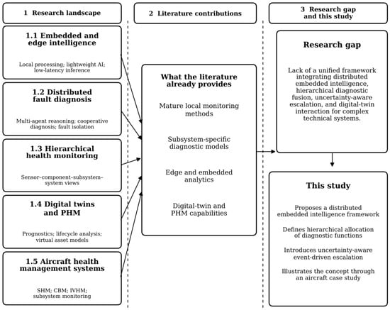
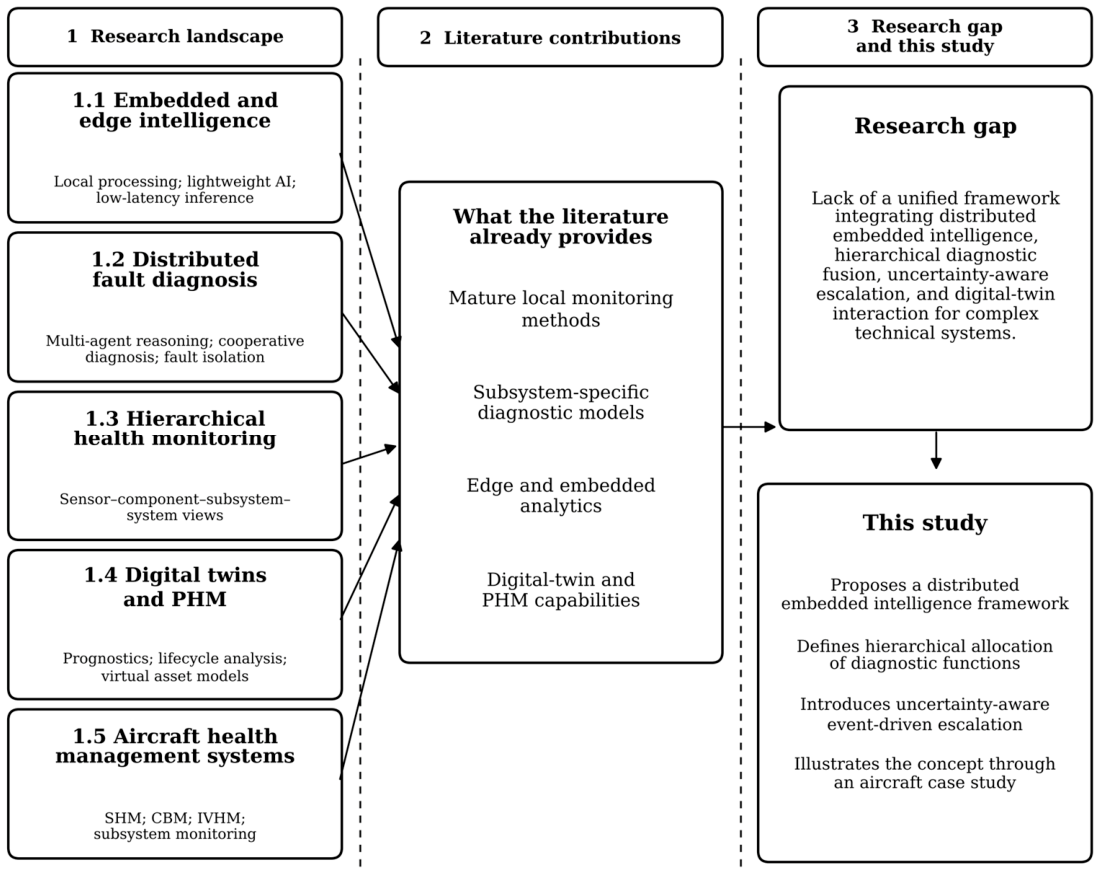
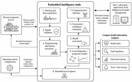
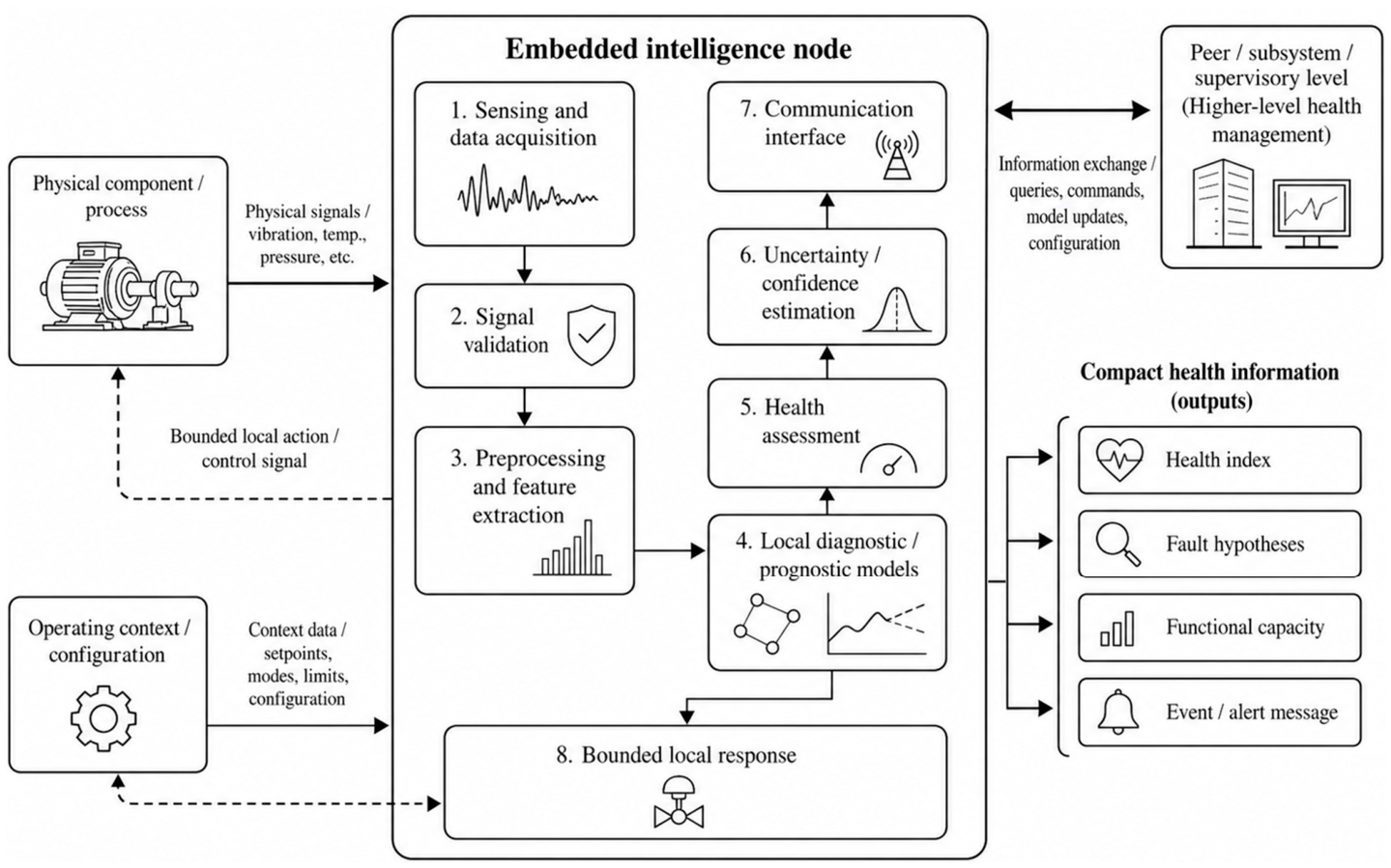
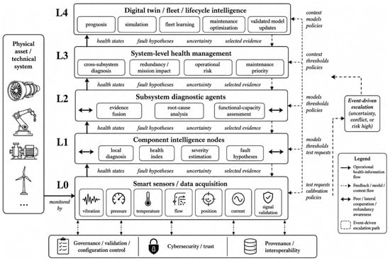
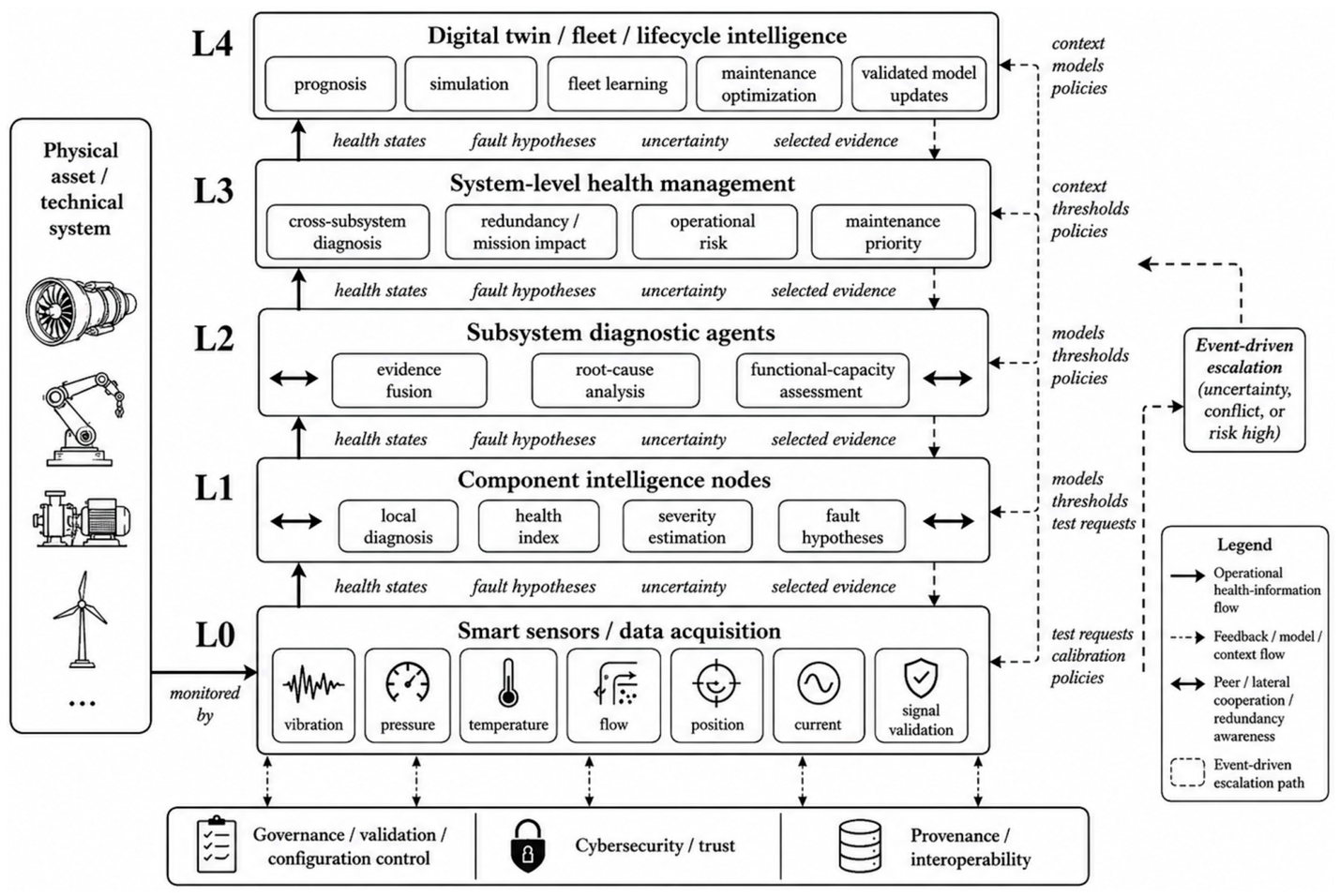
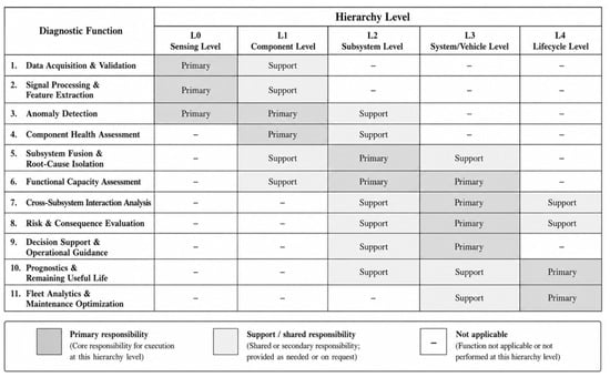
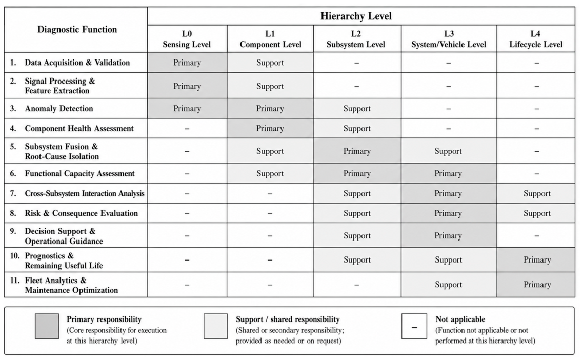
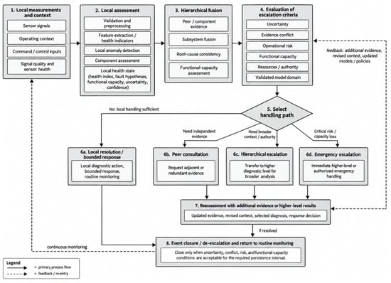
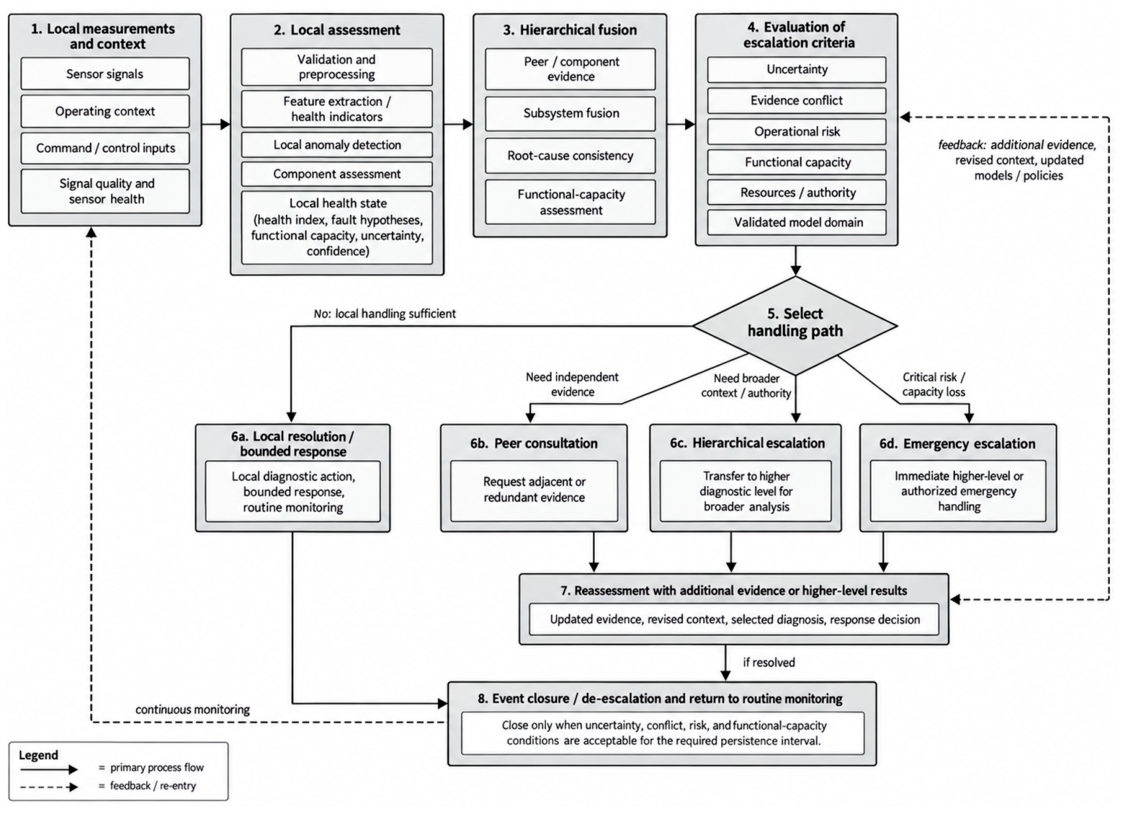
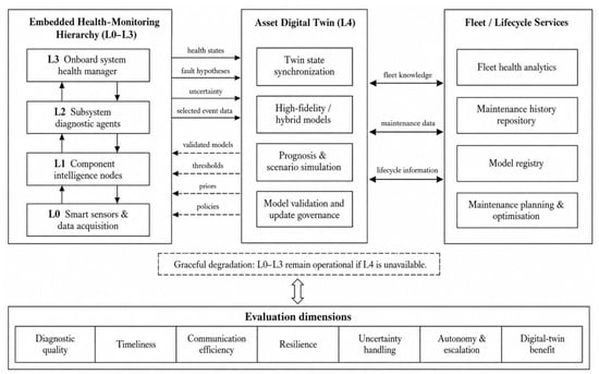
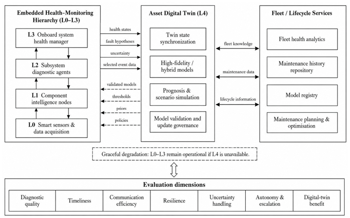
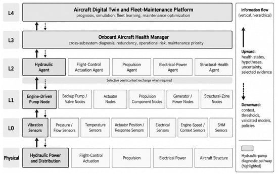
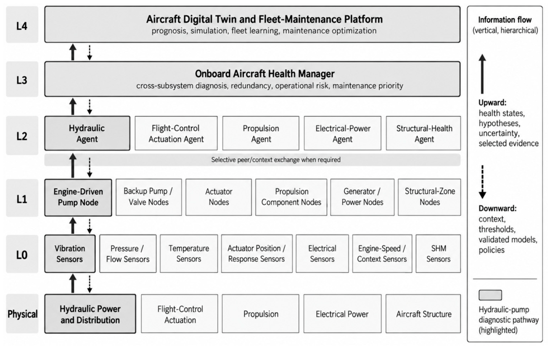
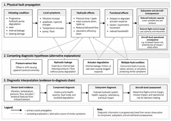
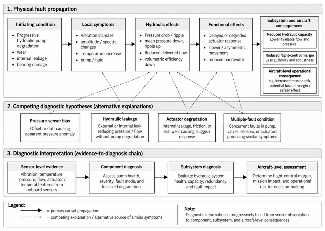
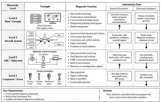
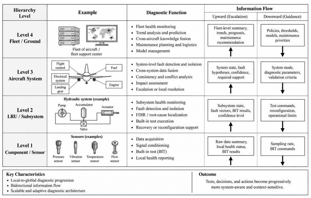
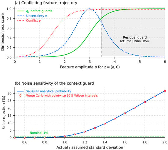
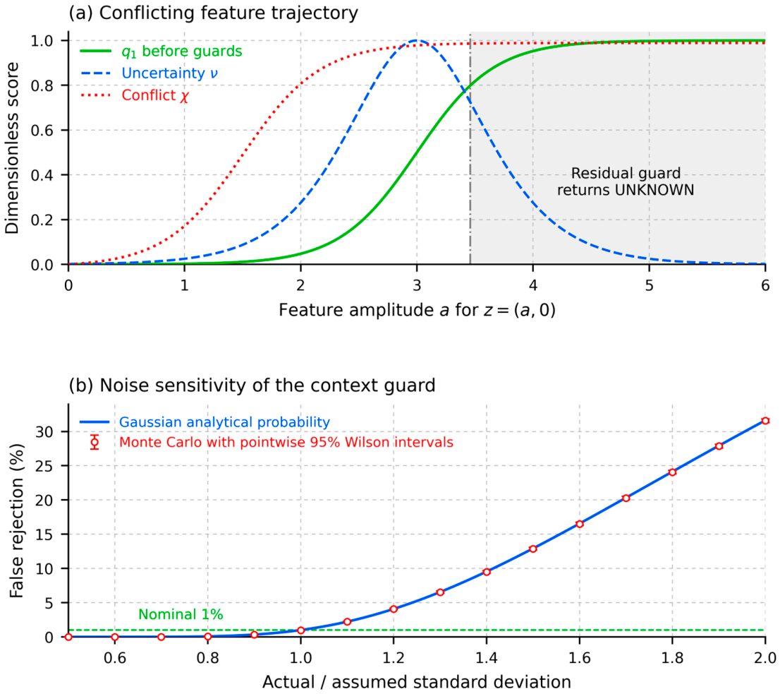

Disclaimer/Publisher’s Note: The statements, opinions and data contained in all publications are solely those of the individual author(s) and contributor(s) and not of MDPI and/or the editor(s). MDPI and/or the editor(s) disclaim responsibility for any injury to people or property resulting from any ideas, methods, instructions or products referred to in the content. |
© 2026 by the author. Licensee MDPI, Basel, Switzerland. This article is an open access article distributed under the terms and conditions of the Creative Commons Attribution (CC BY) license.