


Abstract
With the rapid development of large-scale offshore wind power and long-distance flexible DC transmission, the frequency interaction among offshore wind farms, modular-multilevel-converter-based high-voltage direct-current systems, and onshore AC grids has become increasingly important. Offshore wind turbines are normally decoupled from onshore frequency by converter control. This paper proposes a frequency feature transfer and coordinated control method that uses bounded DC voltage variation as an information carrier. The onshore converter maps the filtered frequency deviation and RoCoF into a constrained DC voltage reference, while a proper band-limited decoder at the offshore terminal extracts the transmitted feature without differentiating the received voltage again. Wind farm support is coordinated with DC voltage margin, rotor speed reserve, and converter current limits. Numerical studies cover an onshore load increase, generation loss, wind power reduction, and restricted support capability; controller-hardware-in-the-loop (CHIL) tests examine the DC voltage transfer path and electrical constraints. The numerical comparisons show an improved frequency nadir and a bounded RoCoF response relative to the two reference methods, while the CHIL waveforms confirm controlled DC voltage transfer and acceptable converter voltage and current behavior. The two validation levels are reported separately to avoid attributing model-based frequency indices to the laboratory platform.
1. Introduction
Large-scale offshore wind power has become an important technical route for low-carbon power systems because of its abundant resources, high utilization hours, and reduced land occupation. As offshore wind farms move farther from shore and increase in capacity, modular-multilevel-converter-based high-voltage direct-current transmission has gradually become the preferred grid connection solution. Compared with HVAC transmission, MMC-HVDC transmission has lower cable charging current, flexible active- and reactive-power control, independent grid support capability, and better adaptability to weak AC systems [1,2,3]. It has therefore been widely adopted in offshore wind integration, asynchronous interconnection, islanded power supply, and renewable energy export projects [4,5]. Related modular DC collection and storage converter developments are reported in [6].
However, the high penetration of power electronic converters changes the frequency dynamic behavior of power systems. In a traditional AC grid, synchronous generators naturally release or absorb kinetic energy when frequency changes. Their rotor speed is directly coupled with the grid frequency, so inertia response appears without additional measurement or control. In contrast, offshore wind turbines connected through full-scale converters are electrically decoupled from the onshore grid frequency. The mechanical speed of the wind turbine, the offshore AC frequency, the DC voltage, and the onshore AC frequency are separated by several converter control loops [7,8,9]. Although this decoupling improves controllability, it also weakens natural frequency support. When a large-load disturbance or generator outage occurs in the onshore grid, the offshore wind farm cannot perceive the frequency event directly unless a communication link or special control mechanism is provided.
Existing studies have proposed several frequency support strategies for wind power systems. The most common methods include inertia emulation based on the frequency derivative, droop control based on frequency deviation, deloading control with reserved active power, and rotor kinetic-energy support [10,11]. A related all-DC offshore collector architecture is discussed in [12], while communication-less frequency support is demonstrated in [13]. These methods can improve the frequency nadir and reduce the rate of change of frequency. Nevertheless, when offshore wind farms are connected through MMC-HVDC systems, the key difficulty is not only how to design the wind turbine frequency support law but also how to transmit the onshore frequency information to the offshore side. Communication-based methods are direct and flexible, but they suffer from time delays, data loss, cyber-security risks, and dependence on communication infrastructure [14,15]. For fast frequency response, even a delay of several hundred milliseconds may reduce the effectiveness of inertia support.
Related power-self-balancing control for parallel DAB converter arrays is reported in [16]. For MMC-HVDC links, communication-free DC voltage-based frequency transfer methods have attracted increasing attention [17,18]. The DC link is not only an energy transmission path but also a dynamic coupling channel between the sending-end and receiving-end converters. When the onshore converter intentionally modifies its DC voltage reference according to the AC grid frequency deviation, the DC voltage fluctuation propagates through the DC cable to the offshore converter. The offshore converter and wind farm can then detect the DC voltage variation and reconstruct the frequency support command. This method uses the inherent electrical dynamics of the HVDC system as the information carrier. Therefore, it has fast response, simple implementation, and high reliability. However, if the DC voltage is used as a frequency information carrier without proper coordination, voltage security and power balance may be affected.
Several studies have analyzed DC voltage droop control, frequency-constrained HVDC operation, and offshore wind farm inertia support [19,20,21]. In these methods, the onshore converter usually adjusts active power according to frequency deviation, while the offshore wind farm changes active power according to DC voltage deviation. Although the basic principle is clear, three problems still require further investigation. First, the DC voltage contains both intentional frequency information and undesired electrical disturbances, such as cable oscillation, converter switching ripple, and power fluctuation. If these components are not separated, the offshore wind farm may respond to non-frequency disturbances. Second, frequency events have different dynamic features, including steady deviations, transient slopes, oscillatory modes, and recovery trends. A simple proportional DC voltage droop cannot accurately transfer these frequency features. Third, the wind farm, offshore converter, and onshore MMC have different physical constraints. Wind turbines are limited by the rotor speed, pitch system, and converter current; MMC stations are limited by the DC voltage margin, arm current, submodule capacitor voltage, and modulation range [22,23,24]. Therefore, a coordinated control algorithm is needed to balance frequency support performance and converter safety.
To address these problems, this paper proposes a frequency feature transfer and coordinated control algorithm for offshore wind MMC-HVDC systems based on DC voltage fluctuation mediation. The word “mediation” indicates that DC voltage is not treated as a passive disturbance variable. Instead, it is actively shaped by the onshore converter, transmitted through the DC network, decoded by the offshore converter, and coordinated with wind turbine active-power control. The proposed method introduces a feature extraction mechanism for onshore frequency deviation and rate of change of frequency, a DC voltage fluctuation mapping law with an adaptive amplitude limitation, and an offshore-side support-power reconstruction strategy. Meanwhile, a coordinated current and voltage limitation mechanism is designed to prevent excessive DC voltage deviation and converter overcurrent during severe frequency events.
Recent work covers MMC dynamics and control, terminal-level tuning, communication-free DC voltage coupling, and cooperative frequency support [25,26,27,28]. Frequency-domain and impedance-based analyses clarify the roles of the converter bandwidth and operating point [29,30]. Related modular DC energy conversion studies address harmonic suppression in DC collectors [31]. Multi-terminal DC power dispatch, supervisory control, and generalized droop are treated in [32,33,34,35], with broader modeling and control frameworks summarized in [36,37]. Converter input admittance shaping [38], high-capacity DC transformer topology and modulation [39], oscillatory interactions between wind farms and HVDC systems [40], and VSC-HVDC inertia emulation [41] further motivate the bounded encoder, band-limited decoder, and constraint-aware wind farm support developed here.
The main contributions are as follows. First, the frequency feature transfer mechanism is formulated from the DC-link energy balance and converter coupling. Second, the onshore encoder and the proper band-limited offshore decoder are designed so that frequency deviation and RoCoF information can be transmitted without repeated differentiation. Third, the wind farm support command is coordinated with DC voltage, rotor speed, and converter current limits. Finally, direct frequency/RoCoF comparisons are carried out under the four stated numerical cases, while the CHIL results are used to assess converter-side feature transfer and electrical constraint compliance.
2. Theoretical Model of Offshore Wind MMC-HVDC System
2.1. Structure and Power Flow Relation
The studied system consists of an offshore wind farm, an offshore AC collection network, an offshore MMC station, a DC transmission cable, an onshore MMC station, and the receiving-end AC grid. The offshore wind farm is composed of multiple permanent-magnet synchronous-generator-based wind turbines with full-scale converters. The offshore MMC regulates the offshore AC voltage and frequency, thereby providing a grid-forming reference for wind turbine converters. The onshore MMC controls the DC voltage and exchanges active and reactive power with the onshore AC grid. Under normal operation, active power is transmitted from the offshore wind farm to the onshore grid through the DC link.
As shown in Figure 1, the offshore wind farm is connected to the offshore MMC station through an AC collection network, and the generated power is transmitted to the onshore MMC station through the DC cable before being delivered to the receiving-end AC grid at the PCC. In this configuration, the offshore MMC mainly regulates the offshore AC voltage and frequency, thereby providing a grid-forming reference for the full-converter wind turbines. The onshore MMC is responsible for maintaining the DC-link voltage and exchanging active and reactive power with the onshore AC grid. The power variables Pac2 and Pdc2 represent the AC-to-DC conversion process at the offshore side, whereas Pdc1 and Pac1 describe the DC-to-AC power transfer at the onshore side. This power flow relationship provides the basis for deriving the energy balance, DC voltage dynamics, and frequency response model of the MMC-HVDC system. The revised sign convention is local to each converter terminal. At the offshore terminal, Pac2 > 0 denotes wind farm power entering Converter 2 and Pdc2 > 0 denotes power leaving Converter 2 toward the DC cable. At the onshore terminal, Pdc1 > 0 denotes power received from the DC cable and Pac1 > 0 denotes power delivered to the AC grid. Losses therefore satisfy Pac2 − Pdc2 = Ploss,2 and Pdc1 − Pac1 = Ploss,1 in steady export operation.
Figure 1.
Topology and positive power flow directions of offshore wind farm connected through MMC-HVDC system (Converter 2: offshore MMC; Converter 1: onshore MMC).
The power balance of the DC link is the starting point for analyzing frequency feature transfer. When the onshore converter changes its DC voltage reference according to the grid frequency, the DC-link stored energy changes [36]. This variation is observed by the offshore converter as a DC voltage fluctuation. Therefore, the DC-link energy equation can express the coupling among the offshore input power, onshore output power, and DC voltage dynamics. For a lumped equivalent DC capacitor, the energy balance is written as
where Cdc is the equivalent DC-link capacitance, udc is the DC voltage, Pow is the active power injected from the offshore wind side, Pg is the active power delivered to the onshore AC grid, and Ploss is the total loss of the DC cable and converters.
This equation shows that the DC voltage is affected by the instantaneous power difference between the offshore and onshore sides. In conventional control, the onshore MMC suppresses this voltage deviation as quickly as possible. In the proposed control framework, a controlled and bounded component is intentionally added to the DC voltage reference so that onshore frequency information can be embedded into the DC voltage. To distinguish the intentional information component from the normal operating value, the DC voltage is decomposed as
where Udc0 is the rated DC voltage, Δudc,f is the intentional DC voltage fluctuation carrying frequency features, and Δudc,d is the undesired DC voltage disturbance caused by wind power fluctuation, cable oscillation, converter ripple, and measurement noise.
The key to DC voltage-mediated frequency transfer is to make Δudc,f recognizable and controllable. If the frequency-related voltage component is too small, the offshore side cannot decode it accurately under noise and operating disturbances [37]. If it is too large, the DC voltage margin and MMC modulation range may be violated. Therefore, the DC voltage fluctuation must be generated according to the onshore frequency event intensity and converter security constraints. The onshore grid frequency deviation is defined as
where fg is the measured onshore grid frequency and f0 is the nominal grid frequency.
Frequency deviation reflects the quasi-steady imbalance between generation and load. However, the early stage of a frequency event is more strongly represented by the rate of change of frequency. For offshore wind frequency support, this derivative component is important because it indicates how rapidly kinetic energy should be released. To reduce noise amplification, the measured frequency is first passed through a first-order filter before the derivative feature is calculated. The filtered frequency feature is expressed as
where Tf is the frequency measurement filter time constant and Δfm is the filtered frequency deviation used for feature extraction.
Based on the filtered frequency deviation, the rate-of-change feature can be obtained. This feature should not be calculated directly from raw frequency measurement because phase-locked-loop noise, sampling error, and grid harmonics may introduce high-frequency spikes [38]. Therefore, the derivative is formed from the filtered signal. The rate-of-change-of-frequency feature is given by
where rf is the filtered rate of change of frequency.
2.2. Onshore MMC Frequency Feature Encoding Model
The onshore MMC is responsible for converting the AC grid frequency feature into a DC voltage fluctuation feature. In conventional DC voltage control, the reference value is constant or slowly adjusted by dispatch commands. In the proposed method, the reference contains an additional frequency-dependent term [39]. This term is designed to include both the frequency deviation and frequency derivative so that the offshore side can perceive not only the magnitude of the frequency event but also its dynamic tendency. The DC voltage reference is defined as
where udc* is the onshore DC voltage reference, ke,p is the proportional frequency-to-voltage coefficient, and ke,d is the RoCoF-to-voltage coefficient.
The proportional term determines the steady transfer gain from grid frequency deviation to DC voltage deviation. The derivative term improves the early response speed and allows the offshore wind farm to release kinetic energy before the frequency nadir is reached. However, both terms must be limited to avoid excessive voltage fluctuation. Considering the upper and lower voltage boundaries of the HVDC system, the practical DC voltage reference is constrained by
where udc,lim* is the limited DC voltage reference, Udc,min is the minimum allowable DC voltage, Udc,max is the maximum allowable DC voltage, and sat(·) is the saturation function.
After the reference is generated, the onshore MMC regulates the DC voltage by changing its active-current command. The outer DC voltage controller transforms the voltage error into the d-axis current reference in the synchronous rotating coordinate system. This relation builds the bridge between the DC voltage information carrier and the AC-side power exchange of the onshore converter. The current reference can be written as
where idg* is the d-axis current reference of the onshore MMC, kpu is the proportional gain of the DC voltage controller, kiu is the integral gain of the DC voltage controller, and id0* is the steady-state active-current feedforward reference.
The q-axis current of the onshore MMC is mainly used for reactive-power or AC voltage support. During frequency events, the converter current capacity must be shared between active frequency support and reactive voltage support. If this coordination is ignored, the current command may exceed the converter limit, causing saturation and deteriorating frequency transfer accuracy. Therefore, the onshore current constraint is expressed as
where iqg* is the q-axis current reference of the onshore MMC and Ig,max is the maximum allowable current of the onshore converter.
The above model indicates that the DC voltage is not an isolated control variable. It is coupled with converter current, active-power, reactive-power, and frequency dynamics. Under the proposed frequency feature transfer mechanism, the DC voltage controller should track the shaped voltage reference accurately but should not excite excessive DC oscillation. Thus, the control bandwidth must be selected between the low-frequency grid frequency dynamics and the high-frequency DC cable electrical resonance.
2.3. Offshore-Side Decoding Model Based on DC Voltage Fluctuation
The offshore MMC cannot directly measure the onshore grid frequency because the offshore AC system is electrically isolated from the receiving-end grid by the DC transmission link. However, once the onshore MMC embeds the frequency feature into the DC voltage reference, the offshore converter can obtain frequency-related information by observing the DC voltage [40]. The difficulty is that the measured DC voltage contains both useful frequency information and unrelated disturbances. Therefore, a decoding model is required to extract the frequency-mediated component from the measured DC voltage.
The measured DC voltage at the offshore terminal can be expressed as
where udc,o is the offshore-side measured DC voltage, Δudc,f,o is the offshore-terminal frequency-related DC voltage component, Δudc,d,o is the offshore-terminal disturbance component, and nu is the measurement noise of the DC voltage sensor.
Because the DC cable has distributed resistance, inductance, and capacitance, the voltage fluctuation generated by the onshore converter is not transmitted to the offshore side without attenuation or phase delay. For the frequency range associated with primary frequency response, the DC cable can be represented by a low-order transfer model. This approximation is suitable because the frequency support dynamics are much slower than switching harmonics and electromagnetic transients. The transfer relation between the onshore encoded voltage component and the offshore received component is described as
where Gdc(s) is the DC-link voltage transfer function, s is the Laplace operator, ωdc is the equivalent natural angular frequency of the DC-link voltage mode, and ζdc is the damping ratio of the DC-link voltage mode.
The offshore converter should extract the low-frequency intentional fluctuation while suppressing high-frequency noise and cable resonance. A band-limited decoding filter is therefore introduced. Its low-frequency range covers grid frequency support dynamics, while its high-frequency attenuation prevents noise from entering the wind turbine power command. The decoded DC voltage feature is obtained as
where Hdec(s) is the proper band-limited decoder, s is the Laplace operator, and ωh and ωl are the high-pass and low-pass corner angular frequencies, respectively.
The decoder is used only to select the frequency band in which the intentional DC voltage feature is expected. The RoCoF component has already been formed by the onshore encoder; therefore, no derivative of the received DC voltage is introduced offshore. The filtered voltage is converted to a support variable by a static gain:
where ξf is the offshore frequency support signal, ko is the static decoding gain, and Δudc,o is the measured offshore DC voltage deviation.
The offshore terminal therefore responds to the sign and time evolution of the feature encoded onshore rather than estimating a second frequency derivative. The high-pass term rejects sensor offset and slow dispatch-related drift, and the low-pass term attenuates measurement noise, converter ripple, and cable resonance components.
2.4. Offshore Wind Farm Active-Power Support Model
The active-power support capability of an offshore wind farm depends on the wind speed, turbine operating point, rotor kinetic energy, converter current margin, and pitch control state. When the wind turbine operates below the rated wind speed and follows maximum-power-point tracking, no steady active-power reserve exists. However, transient power support can still be provided by releasing rotor kinetic energy. When the turbine operates above the rated wind speed or under deloading control, both kinetic energy and reserved aerodynamic power can contribute to frequency support.
The rotor kinetic energy provides the fast transient support capability of the wind turbine. When the grid frequency drops, the wind turbine can temporarily increase the electromagnetic power output above the mechanical input power, causing the rotor to decelerate. This process is equivalent to inertia emulation. The rotor motion equation is written as
where Jr is the equivalent rotor inertia and Pe is the electromagnetic power delivered by the generator-side converter.
According to the decoded frequency support signal, the offshore wind farm generates an additional active-power command. This command should be fast enough to support the receiving-end frequency but limited enough to avoid excessive rotor speed drop. Therefore, the total wind farm active-power reference is defined as the sum of the maximum-power-point reference, deloading reserve term, and frequency support term. The reference is expressed as
where Pwf* is the total active-power reference of the offshore wind farm, Pmppt is the maximum-power-point-tracking power reference, ΔPres is the active-power reserve component, and ΔPf is the frequency-support-power component.
The frequency support component is generated from the decoded DC voltage feature. A proportional part provides sustained support according to the event severity, while a derivative part improves the fast inertial response. To prevent excessive active-power command, the support term is constrained by the turbine and converter limits. The frequency support power is written as
where kw,p is the proportional gain of wind farm frequency support, kif is the integral gain of wind farm frequency support, ΔPf,max− is the maximum downward power adjustment, and ΔPf,max+ is the maximum upward power adjustment.
The upward support limit is mainly determined by the rotor kinetic energy, converter current margin, and deloaded reserve. The downward support limit is usually associated with power curtailment and DC overvoltage prevention. If the rotor speed approaches its lower boundary, the power support must be reduced smoothly to avoid turbine instability. Therefore, the support-power limit is adjusted by a rotor speed security factor:
where ΔPf,rated+ is the rated upward support capability, ωr,min is the minimum allowable rotor speed, and ωr0 is the pre-disturbance rotor speed.
This adaptive limit ensures that the wind farm provides strong support when sufficient kinetic energy is available but automatically weakens the support when the rotor speed becomes too low. In this way, frequency support and turbine mechanical safety are coordinated within the same control structure.
2.5. MMC Electrical Model and Current Constraint
Figure 2 illustrates the electrical structure and average-value representation of the MMC arm. In Figure 2a, each phase leg consists of an upper arm and a lower arm composed of cascaded submodules, arm inductors, and arm resistances. The AC-side phase currents (ia, ib, and ic) interact with the DC-side current (idc) through the energy exchange between the upper and lower arms. The highlighted path indicates the internal circulating current, which is a key dynamic variable affecting arm energy balance, capacitor voltage fluctuation, and converter losses. Figure 2b further simplifies the one-phase leg into an average-value circuit, where the modulation indices mu,x and ml,x determine the inserted submodule voltages, while ucx,u and ucx,l represent the aggregated capacitor voltages of the upper and lower arms. This equivalent model captures the coupling among the AC current, circulating current, DC-link voltage, and arm capacitor energy and therefore provides a foundation for deriving the MMC dynamic equations, designing circulating-current suppression control, and analyzing transient power exchange in the offshore wind MMC-HVDC system.
Figure 2.
Equivalent circuit and average-value modeling structure of MMC arm.
Both offshore and onshore stations adopt three-phase modular multilevel converters. The MMC internal dynamics influence the feasibility of the proposed frequency transfer method because the converter must track active-power and voltage references while keeping arm currents, submodule capacitor voltages, and modulation indices within safe ranges. For each phase, the upper-arm and lower-arm currents are determined by the AC phase current, DC current, and circulating current. The arm current relations are expressed as
where iuj is the upper-arm current of phase j, ilj is the lower-arm current of phase j, idc is the DC current, ij is the AC phase current, izj is the circulating current, and j represents phase a, b, or c.
The above equations show that active-power support is not only an external power control problem. When the wind farm rapidly changes active power, the DC current and AC current of the MMC also change, which may increase arm current stress. Therefore, the frequency support command must be coordinated with the converter current limit. The equivalent current limitation for the MMC arm can be written as
where Iarm,max is the maximum allowable arm current of the MMC.
For converter-level active- and reactive-power control, the AC-side voltage equation in the synchronous rotating frame is used. This model is suitable for designing current controllers and for analyzing the interaction between active and reactive currents. Taking the onshore MMC as an example, the current dynamics are described as
where Lg is the equivalent AC-side inductance, Rg is the equivalent AC-side resistance, id and iq are the d-axis and q-axis converter currents, ud* and uq* are the d-axis and q-axis converter voltage references, ud and uq are the d-axis and q-axis grid voltages, and ωg is the onshore grid angular frequency.
The active and reactive power exchanged by the converter are then obtained from the d-q voltage and current components. If the d-axis is aligned with the grid voltage vector, active power is mainly regulated by id, and reactive power is mainly regulated by iq. The power equations are
where Pg is the active power delivered to the onshore AC grid and Qg is the reactive power exchanged with the onshore AC grid.
Based on the above models, the frequency feature transfer path can be summarized as follows: First, the onshore grid frequency deviation and rate-of-change feature are measured and filtered. Second, the onshore MMC encodes these features into a bounded DC voltage reference fluctuation. Third, the DC cable transmits the voltage fluctuation to the offshore terminal with attenuation and phase delay. Fourth, the offshore converter decodes the received DC voltage fluctuation and generates an equivalent support signal. Finally, the offshore wind farm adjusts active power through rotor kinetic-energy release and reserved power control.
The small-signal transfer relation from onshore frequency deviation to offshore support power can be expressed by combining the encoding, DC transmission, decoding, and wind farm support links. This equivalent transfer model helps evaluate response speed, gain accuracy, and damping performance. The transfer relation is written as
where Gwf(s) is the wind farm active-power support transfer function and Genc(s) is the onshore frequency-to-DC voltage encoding transfer function.
The above expression clarifies the essential mechanism of the proposed method. The onshore frequency feature is not sent through a communication channel but through the controlled dynamic behavior of the DC voltage. The transfer quality depends on the gain and phase characteristics of four links: encoding, DC-link propagation, decoding, and wind farm power response. If the total phase lag is too large, the wind farm may provide support after the frequency nadir, reducing the benefit of inertia emulation. If the gain is too high, the DC voltage and rotor speed may exceed their security limits. Therefore, the coordinated control algorithm must shape both the amplitude and phase of the transfer path.
3. Coordinated Control Algorithm Based on DC Voltage Fluctuation Mediation
3.1. Overall Control Principle
The proposed control algorithm aims to realize communication-free frequency feature transfer from the onshore AC grid to the offshore wind farm while maintaining the secure operation of the MMC-HVDC system. The control system contains four coordinated layers: onshore frequency feature extraction, DC voltage fluctuation encoding, offshore DC voltage decoding, and wind farm active-power support. These layers are not independent. The onshore encoding amplitude must consider the DC voltage margin; the offshore decoding gain must consider noise and cable resonance; the wind farm support command must consider the rotor speed margin and converter current capacity; and the MMC current controller must ensure that active-power support does not violate electrical constraints.
The proposed algorithm uses the DC voltage as a mediated dynamic variable. In normal operation, the DC voltage is regulated around its rated value. During a frequency event, the onshore converter intentionally shifts the DC voltage reference according to the measured frequency feature. The offshore converter detects this shift and reconstructs a support command. When the onshore grid frequency drops, the wind farm increases active-power output, and the DC-link power balance transfers the additional energy to the onshore AC grid. When the frequency recovers, the wind turbine gradually restores the rotor speed and returns to its pre-disturbance operating point.
The control objective can be expressed by a multi-objective function. It includes the frequency support performance, DC voltage security, wind turbine kinetic-energy security, and converter current limitation. The optimization-oriented control target is formulated as
where J is the coordinated control objective, w1 to w5 are weighting coefficients, Δudc is the DC voltage deviation, Iarm is the MMC arm current magnitude, and Iarm,0 is the pre-disturbance arm current magnitude.
This objective does not mean that a complex online optimization must be solved at every sampling instant. Instead, it provides the design principle for the coordinated control law. Frequency deviation and rate of change should be reduced, but not at the cost of excessive DC voltage deviation, rotor speed drop, or arm current overload. The following sections derive the practical control components according to this objective.
3.2. Onshore Frequency Feature Extraction
The first step of the algorithm is to detect whether the onshore grid is experiencing a frequency event. Since raw frequency measurements may include noise and small oscillations, the controller extracts a filtered frequency deviation and a filtered rate-of-change feature. The extraction process contains a dead band to avoid unnecessary DC voltage fluctuation under normal frequency variations. The effective frequency deviation is defined as
where Δfe is the effective frequency deviation after dead-band processing, Δfdb is the frequency dead-band threshold, and sgn(·) is the sign function.
Similarly, the rate-of-change feature should be activated only when the frequency event develops rapidly. This prevents the derivative link from responding to very small frequency fluctuations. The effective rate-of-change feature is defined as
where re is the effective rate-of-change-of-frequency feature and rdb is the rate-of-change dead-band threshold.
The extracted features are then used to generate the DC voltage fluctuation command. In order to make the voltage fluctuation direction consistent with the desired wind farm response, the sign of the mapping coefficient is selected according to the converter power flow convention. In this paper, a frequency drop corresponds to a DC voltage variation that is decoded by the offshore controller as an active-power increase command. The encoded voltage component is given as
where Δuenc is the encoded DC voltage fluctuation command, kep is the frequency deviation encoding gain, and ked is the rate-of-change encoding gain.
The encoded voltage command is further processed by an amplitude limiter and a rate limiter. The amplitude limiter protects the DC insulation and MMC modulation margin, while the rate limiter prevents the excessive excitation of DC cable oscillation. The final onshore DC voltage reference is expressed as
where udc,on* is the final onshore DC voltage reference, rlim[·] is the rate-limiting operator, ΔUdc,max− is the maximum allowable negative DC voltage deviation, and ΔUdc,max+ is the maximum allowable positive DC voltage deviation.
This reference generation strategy ensures that the DC voltage carries meaningful frequency information only when the onshore grid experiences a significant frequency event. In normal operation, the DC voltage reference remains close to its rated value. During severe disturbances, the limiting mechanism guarantees that the frequency transfer function does not endanger DC-link voltage security.
After the onshore MMC generates the frequency-related DC voltage fluctuation, the offshore terminal receives a delayed and attenuated voltage signal. The offshore controller must distinguish the intentional fluctuation from random voltage disturbances caused by wind speed variation, converter switching ripple, cable oscillation, and measurement noise. Therefore, the filter defined by Equation (12) is adopted.
According to the theory presented in Section 2.3, the reconstructed offshore support signal (ξf) is obtained by applying the static offshore decoding gain (ko) and the decoding filter (Hdec(s)) to the onshore-induced DC voltage fluctuation (Δudc,o(s)); the same expression derived in Section 2.3 is reused directly here, and no offshore derivative gain or derivative filter is introduced.
The former downstream filtered differentiator has been removed. Robustness is now obtained by selecting the high-pass corner below the electromechanical support band and the low-pass corner below converter ripple and cable resonance frequencies. A dead band is retained after the static gain to reject residual sensor noise and normal DC voltage ripple. Accordingly, high-frequency gain is bounded, and the physical meaning of the decoder is frequency band selection rather than repeated RoCoF extraction:
where ξe is the effective offshore support signal and ξdb is the support-signal dead-band threshold.
This dead band plays two roles: First, it avoids unnecessary power modulation when the DC voltage only contains normal measurement fluctuation. Second, it prevents the wind farm from responding to small disturbances that can be handled by the onshore converter alone. As a result, the wind farm participates in frequency support only when the event is strong enough to justify kinetic-energy release or reserved-power utilization.
3.3. Wind Farm Coordinated Active-Power Control
The wind farm active-power command is generated by combining the normal maximum-power-point-tracking command and the frequency support command. During a frequency sag, the wind farm should increase output power rapidly. During frequency recovery, the rotor speed should be restored gradually to avoid a secondary frequency dip. Therefore, the support control must include both fast support and smooth recovery.
The basic support-power command is proportional to the effective offshore support signal. An integral term is added to improve sustained support under longer frequency deviations, but the integral action must be limited to prevent over-release of rotor kinetic energy. The preliminary support-power command is given by
where ΔPf0 is the preliminary frequency-support-power command, kwp is the wind farm proportional support gain, and kwi is the wind farm integral support gain.
The available upward support power is related to the rotor speed margin. When the rotor speed is high, more kinetic energy can be released. When the rotor speed approaches its lower limit, support must be reduced. A smooth security coefficient is introduced to avoid sudden power command discontinuity. The rotor speed security coefficient is defined as
where ηω is the rotor speed security coefficient, ωr is the instantaneous rotor angular speed, ωr,min is the minimum allowable rotor angular speed, and ωr0 is the initial rotor angular speed before the frequency event.
In addition to the rotor speed limitation, the generator-side and grid-side converters of each wind turbine have current constraints. The wind farm cannot increase active power indefinitely when the converter current is close to the rated value. Therefore, a converter current security coefficient is introduced. It is defined as
where ηi is the wind turbine converter current security coefficient, Iwt is the instantaneous wind turbine converter current, Iwt0 is the pre-disturbance converter current, and Iwt,max is the maximum allowable converter current.
The final frequency-support-power command is obtained by multiplying the preliminary support command by the security coefficients and applying saturation. This structure guarantees that the wind farm provides strong support when enough mechanical and electrical margins exist but automatically reduces support under stressed operation. The final support-power command is written as
where ΔPf* is the final frequency-support-power command, ΔPdown,max is the maximum downward power regulation capability, and ΔPup,max is the maximum upward power regulation capability.
After the frequency event, the wind turbine must recover rotor speed. If recovery is too fast, the turbine absorbs excessive power from the grid or sharply reduces its output, which may cause a secondary frequency drop. Therefore, this paper adopts a slow recovery law based on rotor speed deviation. The recovery power component is expressed as
where ΔPrec is the rotor speed recovery power correction and krec is the rotor speed recovery gain.
The total wind farm active-power reference is then obtained by adding the normal operating reference, the frequency support component, and the recovery component. During the frequency support stage, ΔPf* dominates. During the recovery stage, ΔPrec gradually restores the rotor speed. The complete active-power reference is
where Pwf* is the wind farm active-power reference and Pmppt is the maximum-power-point-tracking reference.
This coordinated active-power control makes the offshore wind farm behave as a controlled frequency support resource. Unlike communication-based control, the offshore side does not need direct access to onshore frequency measurements. The support command is reconstructed from the DC voltage fluctuation, and the support intensity is adjusted according to the wind turbine operating margins.
Figure 3 presents the hierarchical control structure of the offshore MMC, where the AC voltage loop, the inner current loop, coordinate transformation, and circulating-current suppression control are integrated. The outer AC voltage controller compares the reference voltages Ugd* and Ugq* with the measured voltages ugd and ugq, generating the current references igd* and igq*. These references are then tracked by the inner current controllers, in which the ωL terms are introduced to compensate the cross-coupling between the d- and q-axis dynamics. Through the inverse dq-abc transformation, the resulting voltage commands are converted into three-phase modulation signals for the MMC. In parallel, the circulating-current suppression loop regulates icom,d and icom,q toward their references, reducing internal arm current oscillations and capacitor voltage ripples. This control arrangement enables the offshore MMC to establish a stable AC voltage and frequency reference for the offshore wind farm while maintaining the internal energy balance, which is essential for the dynamic modeling and stability analysis of the MMC-HVDC-connected offshore wind system.
Figure 3.
Control of offshore MMC with AC voltage regulation and circulating-current suppression.
3.4. MMC Current-Limited Coordination
The additional active power supplied by the wind farm must pass through the offshore MMC, DC cable, and onshore MMC. Therefore, converter current limits are critical. If the support command is generated only from frequency deviation, the MMC may enter current saturation during severe disturbances. Current saturation will distort the DC voltage mediation signal and may reduce both frequency support and voltage control performance. To avoid this problem, a current-limited coordination mechanism is introduced.
For the onshore MMC, the total current reference in the d-q frame must not exceed the rated current. When active current increases for frequency support, the available reactive-current margin decreases. The active-current priority coefficient is defined as
where ηg is the onshore MMC active-current priority coefficient, Ig,max is the maximum onshore converter current, iqg* is the q-axis current reference, idg* is the d-axis current reference, and ε is a small positive value used to avoid division by zero.
The limited d-axis current reference is then calculated by multiplying the original reference by the current priority coefficient. This method keeps the current vector inside the allowable circle and avoids abrupt saturation. The limited active-current reference is
where idg,lim* is the current-limited d-axis reference.
For the offshore MMC, the current limitation is related to the active power transferred from the wind farm and the offshore AC voltage controlled by the converter. When the wind farm output increases, the offshore MMC must absorb more active current from the offshore AC network. The offshore current security coefficient is defined as
where ηo is the offshore MMC current security coefficient, Io is the instantaneous offshore MMC current magnitude, Io0 is the pre-disturbance offshore MMC current, and Io,max is the maximum allowable offshore MMC current.
The support-power command sent to the wind farm is finally modified by the offshore and onshore converter current security coefficients. This forms a converter-aware support command. The coordinated support command is expressed as
where ΔPf,coor* is the converter current coordinated frequency-support-power command.
The current-limited coordination mechanism ensures that the frequency support function does not conflict with the basic MMC operation constraints. It also prevents hidden overcurrent in converter arms because the d-q current limitation is combined with arm current monitoring. When the arm current peak approaches its threshold, the support command is reduced before protection action is triggered.
Since the proposed method intentionally uses DC voltage fluctuation as an information carrier, voltage security is the most important constraint. The DC voltage deviation should be large enough to transfer frequency features but small enough to remain within insulation and modulation limits. A dynamic voltage margin coefficient is introduced to evaluate the remaining safe voltage range.
The DC voltage margin coefficient is defined according to the distance between the actual DC voltage and its allowable boundaries. It is expressed as
where ηu is the DC voltage margin coefficient, udc is the instantaneous DC voltage, Udc,min is the minimum allowable DC voltage, Udc,max is the maximum allowable DC voltage, and Udc0 is the rated DC voltage.
When the DC voltage approaches its boundary, the encoded voltage fluctuation and offshore support command should both be weakened. This avoids a situation in which the communication-free frequency support endangers the physical transmission link. The voltage-secured encoding command is therefore modified as
where Δuenc,sec is the voltage-secured encoding command.
3.5. Algorithm Implementation Procedure
Figure 4 describes the integrated control and modulation framework of the MMC-HVDC converter. The upper part gives the equivalent electrical relationship among the AC side, MMC arm capacitors, and DC side, showing that the converter dynamics are governed by the coupling of the AC current, circulating current, capacitor voltage, and DC-link voltage. The average capacitor voltage (vCavgj) represents the stored energy of the phase arm, while the circulating current (icirj) affects both internal energy oscillation and capacitor voltage ripple. In the lower control structure, the vector current control (VCC) regulates the AC-side current components and generates modulation references through the dq-abc transformation. The average voltage control (AVC) maintains the arm capacitor voltage around its desired value, while the CCSC suppresses circulating-current components to improve internal stability. The nearest-level modulation (NLM) determines the inserted submodule numbers Npj and Nnj, and the voltage balancing control (VBC) further distributes switching pulses among submodules. This structure links converter-level control objectives with submodule-level modulation, providing a basis for analyzing the MMC energy balance, voltage stability, and transient response in HVDC transmission systems.
Figure 4.
Modulation of MMC-HVDC converter considering voltage balancing and capacitor energy dynamics.
The proposed control algorithm can be implemented in the digital controllers of the onshore MMC, offshore MMC, and wind farm supervisory controller. No additional communication channel is required between the onshore and offshore stations. The algorithm procedure is summarized as follows:
(1) The onshore MMC measures the grid frequency (fg), calculates the frequency deviation (Δfg), and obtains the filtered frequency deviation (Δfm) and rate-of-change feature (rf). The dead-band functions are applied to obtain the effective frequency deviation (Δfe) and effective rate-of-change feature (re). If both values remain inside the dead band, the DC voltage reference is kept at Udc0.
(2) If a frequency event is detected, the onshore MMC generates the encoded DC voltage fluctuation (Δuenc). The command is processed by amplitude limitation, rate limitation, and DC voltage margin coordination to obtain udc,on*. The onshore MMC tracks the modified DC voltage reference through the outer voltage loop and inner current loop. Meanwhile, the current-limited coordination block constrains idg* and iqg* within the converter current capacity.
(3) The offshore MMC measures the DC voltage, applies the proper band-limited decoder and static gain, and then applies the support-signal dead band. The wind farm supervisory controller calculates the preliminary support-power command and modifies it using the rotor speed, wind turbine current, offshore MMC current, onshore MMC current, and DC voltage security coefficients.
(4) The final coordinated support command (ΔPf,final*) is added to the normal wind farm power reference. Wind turbine converters execute the active-power command while monitoring rotor speed and converter current constraints. When the frequency deviation returns to the dead band, the support command is gradually withdrawn. The recovery controller restores the rotor speed smoothly, preventing secondary frequency sag and DC voltage overshoot.
4. Small-Signal Stability and Robustness Analysis
Figure 5 compares the frequency-domain stability characteristics of the offshore wind MMC-HVDC system under three control strategies: conventional control, DC voltage droop control, and the proposed DC voltage fluctuation-mediated frequency feature transfer method. The magnitude response shows that the conventional control exhibits pronounced resonance peaks in both sub-synchronous and super-synchronous frequency bands, indicating the weak damping of the DC-link and converter interaction modes. Although the DC voltage droop strategy improves low-frequency power sharing, it still produces considerable amplification around the critical resonance frequencies. In contrast, the proposed method significantly suppresses the resonance peaks over the whole frequency range, especially near the 65 Hz super-synchronous mode. The phase response further demonstrates that the proposed method keeps the phase trajectory farther away from the −180° boundary and provides a larger phase margin. This improvement is attributed to the coordinated frequency feature encoding, DC voltage fluctuation limitation, offshore-side decoding, and converter current constraint. Therefore, the proposed strategy not only enables communication-free frequency support information transfer but also enhances damping and reduces the risk of sub-/super-synchronous instability in offshore wind MMC-HVDC integration.
Figure 5.
Frequency-domain comparison of conventional control, DC voltage droop control, and proposed method.
4.1. Band-Limited Decoding and Loop Construction
The stability assessment is based on the complete frequency support path rather than on an isolated converter block. At each operating point, the model is linearized only after confirming that the current and voltage limiters are inactive. The aggregate grid frequency dynamics, onshore encoder, DC-link propagation, band-limited decoder, and wind power response are then connected using the power flow convention defined in Section 2.
The offshore decoder must reject sensor offset and slow dispatch-related variation while attenuating converter ripple and cable resonance. To achieve this, the band-limited transfer function (Hdec(s)) defined in (12) is directly employed. Because its high-frequency magnitude tends to zero, the decoder avoids the unbounded gain of an ideal differentiator, while the onshore encoder remains the sole block that forms the RoCoF feature. The complete open-loop transfer function is then assembled to evaluate the combined phase lag and resonance characteristics:
4.2. Closed-Loop and Noise Path Criteria
The frequency support response and sensor noise response are evaluated separately because satisfactory command tracking can coexist with excessive high-frequency noise gain. With the sign convention of Figure 1, the complementary frequency support transfer is
DC voltage measurement noise enters downstream of the onshore frequency event and therefore follows a different closed-loop path. Its transfer to the wind power command is evaluated over the sensor and converter bandwidth as
Robust operation is assessed from three criteria: positive nominal gain and phase margins, closed-loop poles in the open left half-plane for the prescribed DC-link parameter sweep, and a bounded high-frequency magnitude of the noise-to-power transfer. The same operating point and limiter status are used in the time- and frequency-domain comparisons.
Figure 6 evaluates these properties with the transfer functions and parameter values. The figure is used as a numerical loop-shaping assessment; the CHIL evidence is discussed separately in Section 5.
Figure 6.
Small-signal stability and noise attenuation characteristics of revised frequency feature decoder.
Figure 6 compares the open-loop crossover behavior, decoder bandwidth, and noise-to-power path. The band-limited decoder attenuates very slow DC drift and high-frequency measurement components while retaining the electromechanical support band. Across the five prescribed DC-link parameter combinations, the calculated closed-loop poles remain in the left half-plane and the phase margin remains positive. The decreasing high-frequency noise-to-power magnitude confirms that removing the downstream differentiator eliminates the unbounded noise amplification identified by the reviewer.
5. Controller-Hardware-in-the-Loop Validation and Results
5.1. CHIL Platform and Base Case
To verify the converter-level implementation of the proposed frequency feature transfer and coordinated control algorithm, a 400 MW offshore wind farm connected through a ±320 kV MMC-HVDC transmission system is implemented as a real-time plant model in RTDS and coupled to an external controller, as shown in Figure 7. The system contains an aggregated offshore wind farm, an offshore AC collection network, an offshore MMC station, a 120 km DC submarine cable, an onshore MMC station, and an equivalent receiving-end AC grid. The offshore wind farm is represented by an aggregated permanent-magnet synchronous-generator-based wind turbine model with full-scale power converters. The offshore MMC operates in AC voltage and frequency control mode and provides the voltage reference for the offshore collector system. The onshore MMC operates in DC voltage control and reactive-power control mode under normal operation.
Figure 7.
Controller-hardware-in-the-loop validation platform for MMC-HVDC system.
The proposed strategy is compared with two conventional methods. Method I is the conventional MMC-HVDC control without offshore wind frequency support, in which the onshore converter maintains constant DC voltage and the wind farm follows maximum-power-point tracking. Method II is a conventional DC voltage droop-based support method, in which the offshore wind farm adjusts active power only according to the DC voltage deviation. Method III is the proposed frequency feature transfer and coordinated control algorithm, in which the onshore frequency deviation and rate-of-change feature are encoded into DC voltage fluctuation and decoded by the offshore controller. The system parameters are listed in Table 1.
Table 1.
Main parameters of offshore wind MMC-HVDC system.
5.2. AC Grid and Controller-Hardware-in-the-Loop Models
Two AC grid representations are used for different purposes. A Thévenin source behind an impedance is retained for converter loop screening and short-circuit-ratio sensitivity; it is not used to calculate the frequency nadir. System frequency studies use an aggregate single-area model with synchronous inertia, load damping, primary droop, turbine-governor dynamics, and an excitation block where voltage dynamics are required. The disturbance is introduced as an active-power imbalance at the PCC, so frequency evolves as a state rather than as an imposed reference waveform.
The CHIL arrangement comprises the real-time power system model, the external controller, isolated analogue/digital I/O, voltage and current measurement channels, and a synchronized acquisition computer. Table 2 summarizes the verified platform information and distinguishes it from parameters used only in the supplementary numerical studies.
Table 2.
Verified CHIL architecture, recorded quantities, and numerical-study settings.
The CHIL results are used to assess DC voltage feature transfer, converter currents, AC voltages, and internal-energy behavior. Figure 6, Figure 13 and Figure 14 are model-based analyses and do not depend on an unreported controller sampling rate or a manufacturer-specific CHIL setting. Their numerical parameters are stated with the corresponding models and scripts.
5.3. Frequency Event and Constraint Test Scenarios
The validation matrix separates physical frequency events from auxiliary robustness tests. Case A connects an additional onshore load; Case B removes an equivalent amount of synchronous generation or mechanical input; both create a genuine active-power deficit and are used for frequency nadir and RoCoF comparisons. Case C changes the wind farm power while the onshore balance is unchanged and therefore tests whether slow DC variation is rejected. Case D enforces the converter current or power limitation and tests whether the coordination layer degrades support smoothly. A direct frequency reference step is permitted only for channel identification tests and is not used as evidence of system-level frequency support.
The numerical scenario matrix uses a common event time of 2 s. The imbalance magnitudes are 0.10, 0.12, 0.08, and 0.11 p.u. for Cases A–D, respectively; the wind support limits are 0.14, 0.14, 0.12, and 0.08 p.u. The aggregate model uses H = 4.0 s, D = 1.2 p.u., R = 0.05, Tg = 0.45 s, and Tw = 0.12 s.
5.4. Results Analysis
Figure 8 illustrates the mechanism by which the proposed method encodes frequency support features into controlled DC voltage fluctuations. When the system requires additional active-power support, the DC voltage reference is intentionally shifted to 0.95 p.u.; when the support command is reversed, the reference is raised to 1.05 p.u. The measured DC voltage accurately follows these bounded reference changes with limited overshoot, showing that the DC link can serve as a reliable dynamic information channel between the onshore and offshore converters. The capacitor energy of MMC 1 remains close to its nominal value throughout the process, which indicates that the voltage modulation does not introduce severe internal energy imbalance. The lower subplot shows the adaptive decoding gain (kcoma), which decreases to 190 during negative voltage deviation and increases to 210 during positive voltage deviation. This adaptive adjustment improves the sensitivity of offshore-side frequency feature reconstruction while avoiding excessive response under small disturbances.
Figure 8.
DC voltage feature encoding and adaptive decoding gain under positive and negative frequency support commands.
Figure 9 shows the multi-domain dynamic response of the offshore wind MMC-HVDC system when the offshore wind farm power command changes under the proposed DC voltage fluctuation-mediated control. The offshore wind power follows step variations from 1.0 p.u. to 0.8 p.u., 0.9 p.u., and 0.6 p.u., representing different wind power operating levels and available kinetic-energy margins. During these changes, the PCC voltage and offshore AC voltage remain balanced and sinusoidal, indicating that the MMC stations preserve AC-side voltage quality while transmitting frequency support information through the DC link. The DC voltage is maintained close to 1.0 p.u., with only small transient deviations, which verifies that the proposed control uses DC voltage fluctuation as a bounded information carrier rather than allowing uncontrolled voltage oscillation. Meanwhile, the stored energies of MMC 1 and MMC 2 remain nearly constant, demonstrating that the coordinated voltage–current limitation prevents excessive capacitor energy imbalance.
Figure 9.
Dynamic responses of offshore wind power, PCC/offshore AC voltages, DC voltage, and MMC stored energy under DC voltage-mediated frequency feature transfer. Dashed traces denote corresponding command or reference value, whereas solid traces denote measured response; vertical dotted lines mark command change instants.
Figure 10 shows the current coordination process of the onshore MMC during the frequency support event. After the disturbance occurs, the d-axis current increases rapidly to enhance active-power delivery to the onshore AC grid, while the q-axis current remains at a relatively low level to preserve the converter current margin. The total current rises during the transient support interval but remains below the current limitation boundary, indicating that the proposed coordination strategy can provide additional active-power support without violating the MMC current constraint. The temporary reduction and recovery of the d-axis current around the peak support instant reflect the current-limited redistribution between active support demand and converter security. This result demonstrates that the proposed method does not simply increase the active current aggressively; instead, it coordinates the d-axis current, q-axis current, and total current magnitude to avoid overcurrent risk. Therefore, the MMC can participate in fast frequency support while maintaining safe converter operation.
Figure 10.
Coordinated d- and q-axis current response of onshore MMC under converter current limitation.
Figure 11 compares the DC-link voltage responses under conventional control, DC voltage droop control, and the proposed frequency feature transfer method. Under conventional control, the DC voltage exhibits the largest transient dip and oscillation after the frequency event, indicating insufficient coordination between onshore power support and DC-link voltage regulation. The DC voltage droop strategy reduces the voltage deviation to some extent, but a noticeable voltage depression remains because the droop action directly couples frequency support with DC voltage variation. In contrast, the proposed method produces the smallest voltage fluctuation and the fastest recovery toward the rated value. This improvement is achieved by treating the DC voltage as a bounded information carrier rather than as an uncontrolled disturbance channel. The proposed controller encodes frequency features into limited DC voltage deviations and coordinates offshore decoding with converter current constraints. As a result, the DC voltage remains well within the security boundary, confirming that communication-free frequency feature transfer can be realized without sacrificing HVDC voltage stability.
Figure 11.
DC-link voltage responses under different frequency support control strategies. Line styles are defined consistently: conventional control—black dashed line; DC voltage droop—blue dashed–dotted line; proposed method—red solid line. Markers are used at sparse intervals so the curves remain distinguishable in grayscale printing.
Figure 12 compares the transient electromagnetic responses of the MMC-HVDC system under two representative control changes: control-mode transition and current inner-loop bandwidth variation. In the left panels, the converter switches from the initial operating mode to the proposed coordinated mode. Before the transition, the voltage and current waveforms contain strong oscillatory components; after the transition, the three-phase voltages become more regular, and the currents gradually decay to a stable sinusoidal pattern, indicating that the proposed control improves damping and suppresses converter-side oscillation. In the right panels, the current inner-loop bandwidth is changed to emulate controller retuning or operating-condition variation. The voltage waveform remains bounded, while the current exhibits a short transient increase before settling into a stable periodic response. This result shows that the system is sensitive to inner-loop bandwidth, but the coordinated control structure can still maintain acceptable voltage and current behavior.
Figure 12.
Transient waveforms under control-mode transition and inner-loop bandwidth variation.
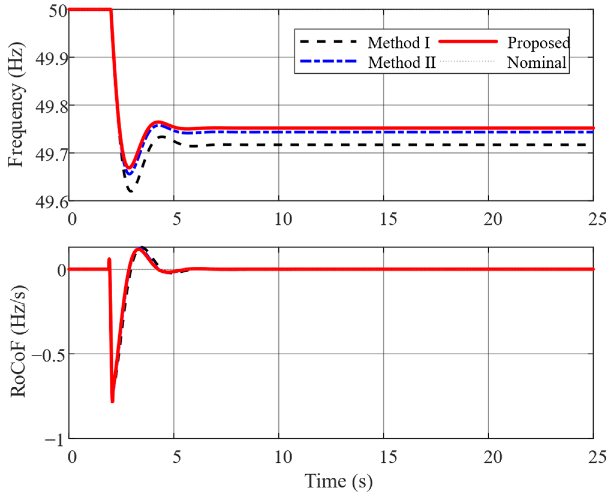
As shown in Figure 13, a 0.12 p.u. load increase is applied at t = 2 s to the same aggregate grid model. Method I provides no wind frequency support, Method II applies proportional support, and the proposed method combines proportional and bounded RoCoF-dependent terms. For a fair comparison, the frequency nadir is obtained from the unfiltered signal, whereas the RoCoF is calculated after applying the same 101-sample Savitzky–Golay filter to all three responses. Method I exhibits the lowest nadir, approximately 49.62 Hz, and the largest steady-state frequency deviation. Method II raises the nadir to about 49.65 Hz, while the proposed method further improves it to approximately 49.66–49.67 Hz and reaches the highest post-disturbance frequency. The lower panel shows an initial RoCoF minimum of approximately −0.8 Hz/s, followed by a short positive rebound and rapid convergence toward zero. Although the initial RoCoF trajectories are similar, the proposed controller reduces the duration of the frequency excursion. Its bounded RoCoF term also prevents an unrealistic impulsive power command at disturbance initiation.
Figure 13.
Comparison of onshore grid frequency and consistently filtered RoCoF under 0.12 p.u. load increase.
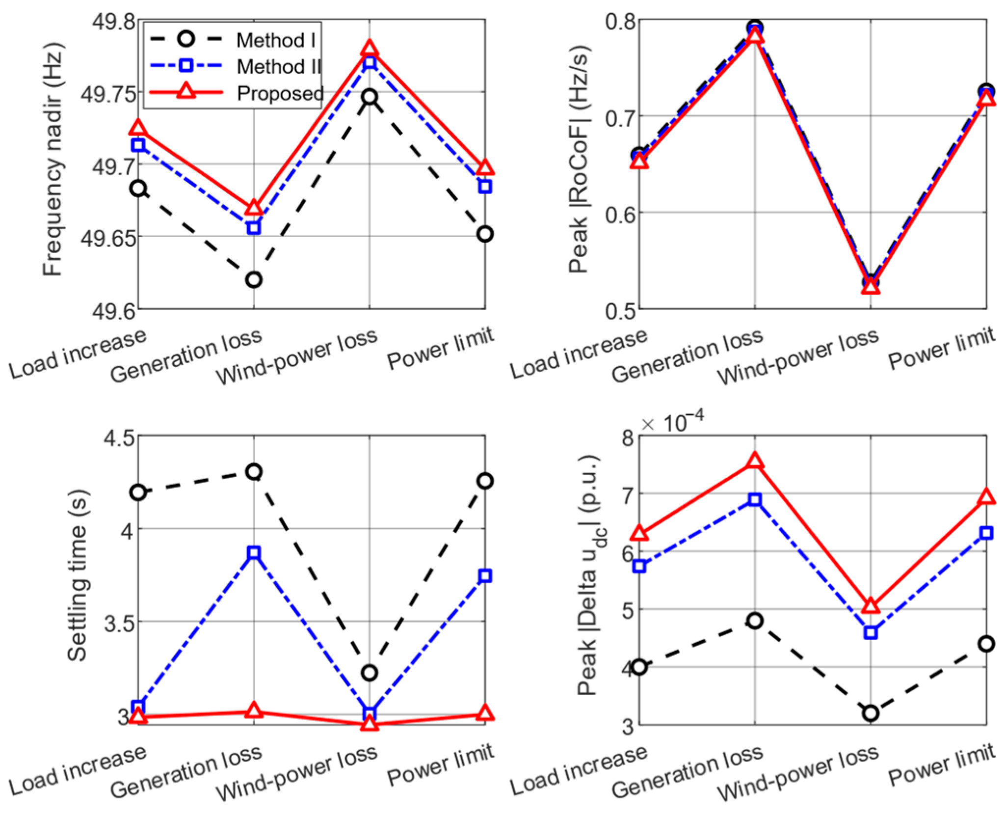
As shown in Figure 14, four performance indices are evaluated separately to distinguish improvements in frequency regulation from changes in the settling time and DC voltage utilization. Cases A and B represent onshore power deficit disturbances, Case C considers a reduction in wind power input, and Case D imposes the most restrictive wind support limit. The proposed method produces the highest frequency nadir and the lowest peak RoCoF in the imbalance-dominated cases, A and B, confirming the effectiveness of the coordinated proportional and bounded RoCoF support. It also shortens the settling time relative to Methods I and II. In Case C, the improvement becomes smaller because the available wind power is reduced. The benefit is further limited in Case D because the supplementary power command reaches its prescribed saturation boundary. Nevertheless, the peak DC voltage deviation remains within a narrow range in all cases, indicating that frequency support does not require the excessive use of the DC voltage margin. The results therefore demonstrate both the effectiveness and the operating limits of the proposed method. These comparisons are deterministic numerical results obtained using the parameters specified in the accompanying script rather than experimental measurements.
Figure 14.
Frequency nadirs, peak absolute RoCoFs, settling times, and peak DC voltage deviations for four operating cases and three control methods.
6. Conclusions
This paper develops a communication-free frequency feature transfer and coordinated control method for offshore wind MMC-HVDC systems. The onshore encoder maps the filtered frequency deviation and RoCoF into a bounded DC voltage reference, while the revised offshore decoder uses a proper band-limited filter and a static gain, thereby avoiding repeated differentiation. The wind farm command is coordinated with DC voltage, rotor speed, and converter current limits. Under the four declared numerical cases, the proposed method improves the frequency nadir and limits the RoCoF response relative to the two reference methods; the benefit decreases when the available wind support power is restricted. The converter-level CHIL waveforms confirm controlled DC voltage feature transfer and acceptable electrical behavior, but they are not used as direct measurements of aggregate-grid frequency performance. Future work will examine larger network models, parameter identification from synchronized measurements, and field-scale validation.
Author Contributions
Conceptualization, J.M., Q.Y. and Z.C.; methodology, J.M., L.F. and J.L.; software, J.M. and J.L.; validation, J.M., L.F. and W.H.; formal analysis, J.M. and L.F.; investigation, J.M. and J.L.; resources, Q.Y., W.H. and Z.C.; data curation, J.M. and W.H.; writing—original draft preparation, J.M.; writing—review and editing, Q.Y., L.F., J.L., W.H. and Z.C.; visualization, J.M. and J.L.; supervision, Q.Y. and Z.C.; project administration, Q.Y. and Z.C.; funding acquisition, Q.Y. and Z.C. All authors have read and agreed to the published version of the manuscript.
Funding
This research was funded by the State Grid Zhejiang Electric Power Corporation (Zhejiang Power Grid Energy Port Project), grant number 5211DS25000A.
Data Availability Statement
The original contributions presented in this study are included in the article. Further inquiries can be directed to the corresponding author(s).
Conflicts of Interest
Junchao Ma, Le Fang, Jianing Liu and Wen Hua are being employed by State Grid Zhejiang Electric Power Co., Ltd. The remaining authors declare that the research was conducted in the absence of any commercial or financial relationships that could be construed as a potential conflict of interest.
Nomenclature
| Symbol | Definition |
| Δfg | Onshore grid frequency deviation |
| rf | Filtered rate of change of frequency |
| ke,p | Frequency deviation encoding gain |
| ke,d | RoCoF encoding gain |
| Δuenc | Encoded DC voltage fluctuation command |
| Gdc(s) | DC-link propagation transfer function |
| Hdec(s) | Proper band-limited offshore decoder |
| ωh, ωl | High-pass and low-pass corner angular frequencies |
| ko | Static offshore decoding gain |
| ξe | Effective offshore support signal after dead band |
| ΔPf* | Final wind farm frequency support command |
| ηω | Rotor speed security coefficient |
| ηi | Wind turbine converter current security coefficient |
| ηg, ηo | Onshore and offshore MMC current security coefficients |
| ηu | DC voltage margin coefficient |
| Iarm | MMC arm current magnitude |
References
- Marquardt, R. Modular multilevel converter: A universal concept for HVDC-networks and extended DC-bus-applications. In Proceedings of the 2010 International Power Electronics Conference, Sapporo, Japan, 21–24 June 2010; pp. 502–507. [Google Scholar]
- Lesnicar, A.; Marquardt, R. An innovative modular multilevel converter topology suitable for a wide power range. In Proceedings of the IEEE Power Tech Conference, Bologna, Italy, 23–26 June 2003; pp. 1–6. [Google Scholar]
- Debnath, S.; Qin, J.; Bahrani, B.; Saeedifard, M.; Barbosa, P. Operation, control, and applications of the modular multilevel converter: A review. IEEE Trans. Power Electron. 2015, 30, 37–53. [Google Scholar] [CrossRef] [Scilit]
- Flourentzou, N.; Agelidis, V.G.; Demetriades, G.D. VSC-based HVDC power transmission systems: An overview. IEEE Trans. Power Electron. 2009, 24, 592–602. [Google Scholar] [CrossRef] [Scilit]
- Adam, G.P.; Anaya-Lara, O.; Burt, G.M.; Telford, D.; Williams, B.; McDonald, J. Modular multilevel inverter: Pulse width modulation and capacitor balancing technique. IET Power Electron. 2010, 3, 702–715. [Google Scholar] [CrossRef] [Scilit]
- An, F.; Zhao, B.; Cui, B.; Chen, Y.; Qu, L.; Yu, Z.; Zeng, R. DC Cascaded Energy Storage System Based on DC Collector with Gradient Descent Method. IEEE Trans. Ind. Electron. 2024, 71, 1594–1605. [Google Scholar] [CrossRef] [Scilit]
- Beerten, J.; Cole, S.; Belmans, R. Modeling of multi-terminal VSC HVDC systems with distributed DC voltage control. IEEE Trans. Power Syst. 2014, 29, 34–42. [Google Scholar] [CrossRef] [Scilit]
- Xu, L.; Yao, L.; Sasse, C. Grid integration of large DFIG-based wind farms using VSC transmission. IEEE Trans. Power Syst. 2007, 22, 976–984. [Google Scholar] [CrossRef] [Scilit]
- Morren, J.; de Haan, S.W.H.; Kling, W.L.; Ferreira, J.A. Wind turbines emulating inertia and supporting primary frequency control. IEEE Trans. Power Syst. 2006, 21, 433–434. [Google Scholar] [CrossRef] [Scilit]
- Kayikci, M.; Milanovic, J.V. Dynamic contribution of DFIG-based wind plants to system frequency disturbances. IEEE Trans. Power Syst. 2009, 24, 859–867. [Google Scholar] [CrossRef] [Scilit]
- Ramtharan, G.; Jenkins, N.; Ekanayake, J.B. Frequency support from doubly fed induction generator wind turbines. IET Renew. Power Gener. 2007, 1, 3–9. [Google Scholar] [CrossRef] [Scilit]
- An, F.; Zhao, B.; Cui, B.; Bai, R. Multi-Functional DC Collector for Future All-DC Offshore Wind Power System: Concept, Scheme, and Implement. IEEE Trans. Ind. Electron. 2022, 69, 8134–8145. [Google Scholar] [CrossRef] [Scilit]
- Saborío-Romano, O.; Bidadfar, A.; Sakamuri, J.N.; Zeni, L.; Göksu, Ö.; Cutululis, N.A. Communication-less frequency support from offshore wind farms connected to HVdc via diode rectifiers. IEEE Trans. Sustain. Energy 2021, 12, 441–450. [Google Scholar] [CrossRef] [Scilit]
- Gontijo, G.F.; Bakhshizadeh, M.K.; Kocewiak, L.H.; Teodorescu, R. State space modeling of an offshore wind power plant with an MMC-HVDC connection for an eigenvalue-based stability analysis. IEEE Access 2022, 10, 82844–82869. [Google Scholar] [CrossRef] [Scilit]
- Yang, B.; Liu, B.; Zhou, H.; Wang, J.; Yao, W.; Wu, S.; Shu, H.; Ren, Y. A critical survey of technologies of large offshore wind farm integration: Summary, advances, and perspectives. Prot. Control Mod. Power Syst. 2022, 7, 17. [Google Scholar] [CrossRef] [Scilit]
- An, F.; Song, W.; Yu, B.; Yang, K. Model Predictive Control with Power Self-Balancing of the Output Parallel DAB DC–DC Converters in Power Electronic Traction Transformer. IEEE J. Emerg. Sel. Top. Power Electron. 2018, 6, 1806–1818. [Google Scholar] [CrossRef] [Scilit]
- Lin, H.; Xue, T.; Lyu, J.; Cai, X. Impact of different AC voltage control modes of wind-farm-side MMC on stability of MMC-HVDC with offshore wind farms. J. Mod. Power Syst. Clean Energy 2023, 11, 1687–1699. [Google Scholar] [CrossRef] [Scilit]
- Han, H.; Li, Q.; Li, Q. Frequency support control of multi-terminal direct current system integrated offshore wind farms considering direct current side stability. Electronics 2023, 12, 3029. [Google Scholar] [CrossRef] [Scilit]
- Zhang, H.; Xiang, W.; Wen, J. Dual grid-forming control with energy regulation capability of MMC-HVDC system integrating offshore wind farms and weak grids. IEEE Trans. Power Syst. 2024, 39, 261–272. [Google Scholar] [CrossRef] [Scilit]
- Li, H.; Li, Y.; Meng, Y.; Yan, K. Coordinated frequency support strategy for VSC-HVDC integrated offshore wind farm system. Front. Energy Res. 2024, 12, 1351353. [Google Scholar] [CrossRef] [Scilit]
- Sun, K.; Zhou, H.; Yao, W.; Xiao, B.; Wen, J. Comprehensive control of MMC-HVDC integrated offshore wind farm system including optimized energy control for fast frequency support. J. Mod. Power Syst. Clean Energy 2025, 13, 1966–1979. [Google Scholar] [CrossRef] [Scilit]
- Wang, W.; Li, Y.; Cao, Y.; Häger, U.; Rehtanz, C. Adaptive droop control of VSC-MTDC system for frequency support and power sharing. IEEE Trans. Power Syst. 2018, 33, 1264–1274. [Google Scholar] [CrossRef] [Scilit]
- Rocabert, J.; Luna, A.; Blaabjerg, F.; Rodríguez, P. Control of power converters in AC microgrids. IEEE Trans. Power Electron. 2012, 27, 4734–4749. [Google Scholar] [CrossRef] [Scilit]
- Saad, H.; Dennetière, S.; Mahseredjian, J.; Delarue, P.; Guillaud, X.; Peralta, J.; Nguefeu, S. Modular multilevel converter models for electromagnetic transients. IEEE Trans. Power Deliv. 2014, 29, 1481–1489. [Google Scholar] [CrossRef] [Scilit]
- Antonopoulos, A.; Angquist, L.; Nee, H.P. On dynamics and voltage control of the modular multilevel converter. In Proceedings of the 13th European Conference on Power Electronics and Applications, Barcelona, Spain, 8–10 September 2009; pp. 1–10. [Google Scholar]
- Haro-Larrode, M.; Santos-Mugica, M.; Etxegarai, A.; Eguia, P. Methodology for Tuning MTDC Supervisory and Frequency-Response Control Systems at Terminal Level under Over-Frequency Events. Energies 2020, 13, 2807. [Google Scholar] [CrossRef] [Scilit]
- Rafferty, J.; Xu, L.; Wang, Y.; Xu, G.; Alsokhiry, F. Frequency support using multi-terminal HVDC systems based on DC voltage manipulation. IET Renew. Power Gener. 2016, 10, 1393–1401. [Google Scholar] [CrossRef] [Scilit]
- Xiong, Y.; Yao, W.; Yao, Y.; Fang, J.; Ai, X.; Wen, J.; Cheng, S. Distributed Cooperative Control of Offshore Wind Farms Integrated via MTDC System for Fast Frequency Support. IEEE Trans. Ind. Electron. 2023, 70, 4693–4704. [Google Scholar] [CrossRef] [Scilit]
- Lyu, J.; Cai, X.; Molinas, M. Frequency Domain Stability Analysis of MMC-Based HVdc for Wind Farm Integration. IEEE J. Emerg. Sel. Top. Power Electron. 2016, 4, 141–151. [Google Scholar] [CrossRef] [Scilit]
- Wu, W.; Wang, L.; Kocewiak, L.H. Impedance-Based Stability Analysis of Voltage-Controlled MMCs Feeding Linear AC Systems. IEEE J. Emerg. Sel. Top. Power Electron. 2020, 8, 4060–4074. [Google Scholar] [CrossRef] [Scilit]
- An, F.; Zhao, B.; Cui, B.; Chen, Y.; Qu, L.; Yu, Z.; Zeng, R. Selective Virtual Synthetic Vector Embedding for Full-Range Current Harmonic Suppression of the DC Collector. IEEE Trans. Power Electron. 2023, 38, 2577–2588. [Google Scholar] [CrossRef] [Scilit]
- Xu, L.; Yao, L. DC voltage control and power dispatch of a multi-terminal HVDC system for integrating large offshore wind farms. IET Renew. Power Gener. 2011, 5, 223–233. [Google Scholar] [CrossRef] [Scilit]
- Assis, T.M.L.; Kuenzel, S.; Pal, B.C. Impact of Multi-Terminal HVDC Grids on Enhancing Dynamic Power Transfer Capability. IEEE Trans. Power Syst. 2017, 32, 2652–2662. [Google Scholar] [CrossRef] [Scilit]
- Papangelis, L.; Debry, M.S.; Panciatici, P.; Van Cutsem, T. Coordinated Supervisory Control of Multi-Terminal HVDC Grids: A Model Predictive Control Approach. IEEE Trans. Power Syst. 2017, 32, 4673–4683. [Google Scholar] [CrossRef] [Scilit]
- Rouzbehi, K.; Miranian, A.; Candela, J.I.; Luna, A.; Rodriguez, P. A Generalized Voltage Droop Strategy for Control of Multiterminal DC Grids. IEEE Trans. Ind. Appl. 2015, 51, 607–618. [Google Scholar] [CrossRef] [Scilit]
- Chaudhuri, N.R.; Majumder, R.; Chaudhuri, B.; Pan, J. Multi-Terminal Direct-Current Grids: Modeling, Analysis, and Control; Wiley-IEEE Press: Hoboken, NJ, USA, 2014. [Google Scholar]
- Van Hertem, D.; Gomis-Bellmunt, O.; Liang, J. (Eds.) HVDC Grids: For Offshore and Supergrid of the Future; Wiley-IEEE Press: Hoboken, NJ, USA, 2016. [Google Scholar]
- Harnefors, L.; Bongiorno, M.; Lundberg, S. Input-Admittance Calculation and Shaping for Controlled Voltage-Source Converters. IEEE Trans. Ind. Electron. 2007, 54, 3323–3334. [Google Scholar] [CrossRef] [Scilit]
- An, F.; Zhao, B.; Cui, B.; Ma, Y.; Zhang, X.; Tang, X.; Dong, L. Asymmetric Topology Design and Quasi-Zero-Loss Switching Composite Modulation for IGCT-Based High-Capacity DC Transformer. IEEE Trans. Power Electron. 2023, 38, 4745–4759. [Google Scholar] [CrossRef] [Scilit]
- Amin, M.; Molinas, M. Understanding the Origin of Oscillatory Phenomena Observed Between Wind Farms and HVDC Systems. IEEE J. Emerg. Sel. Top. Power Electron. 2017, 5, 378–392. [Google Scholar] [CrossRef] [Scilit]
- Zhu, J.; Booth, C.D.; Adam, G.P.; Roscoe, A.J.; Bright, C.G. Inertia Emulation Control Strategy for VSC-HVDC Transmission Systems. IEEE Trans. Power Syst. 2013, 28, 1277–1287. [Google Scholar] [CrossRef] [Scilit]
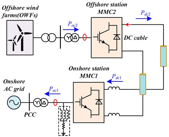
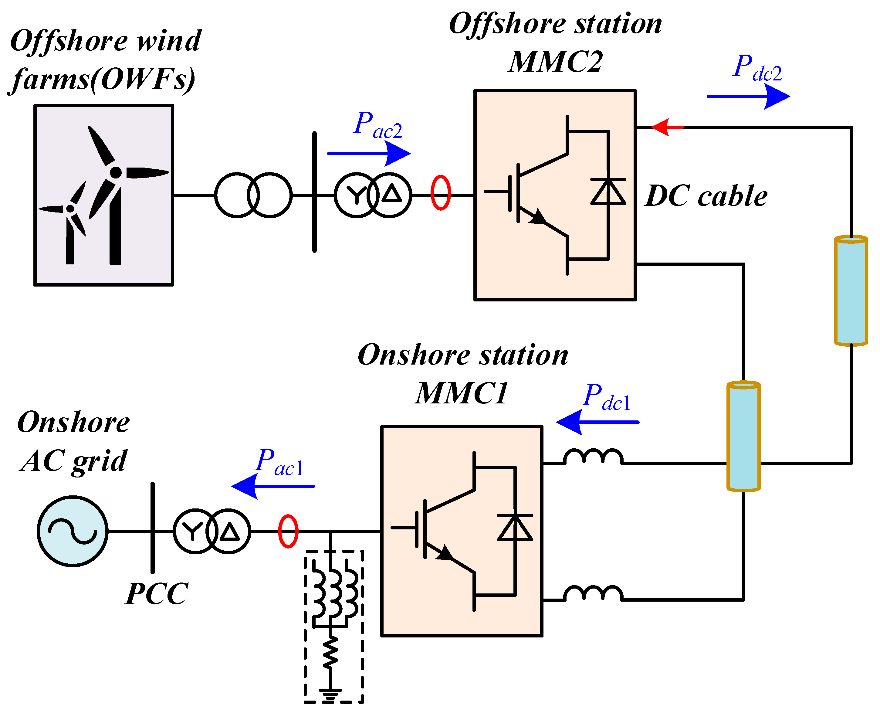
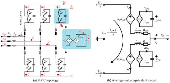
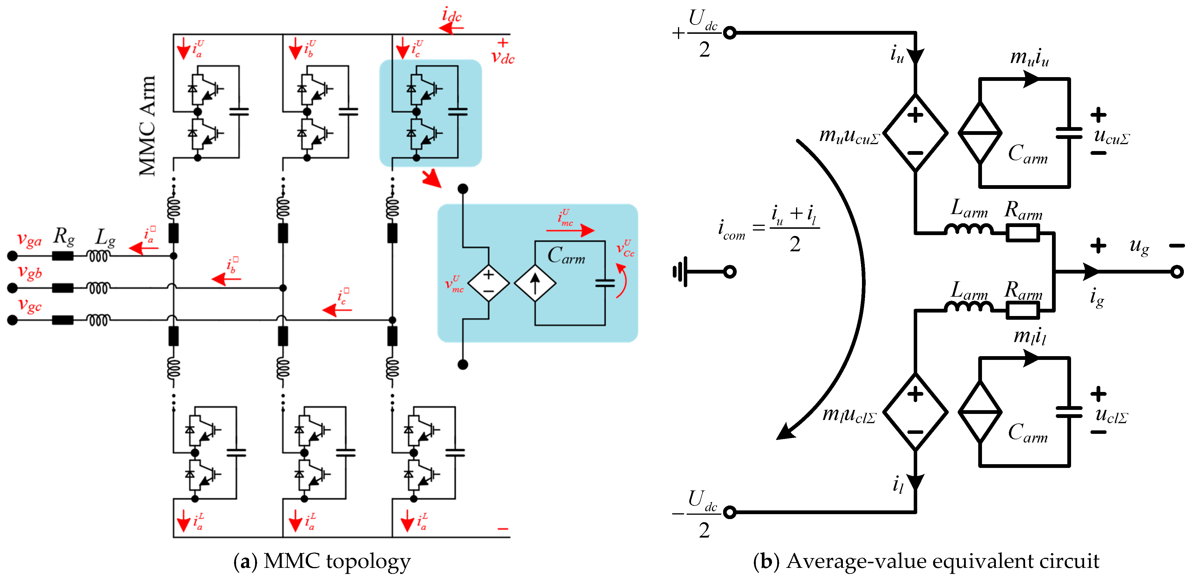
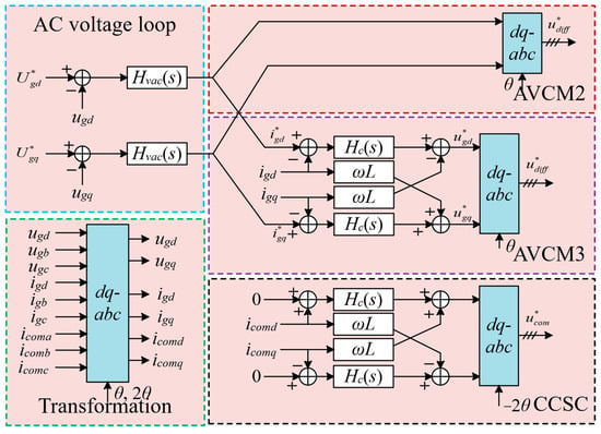
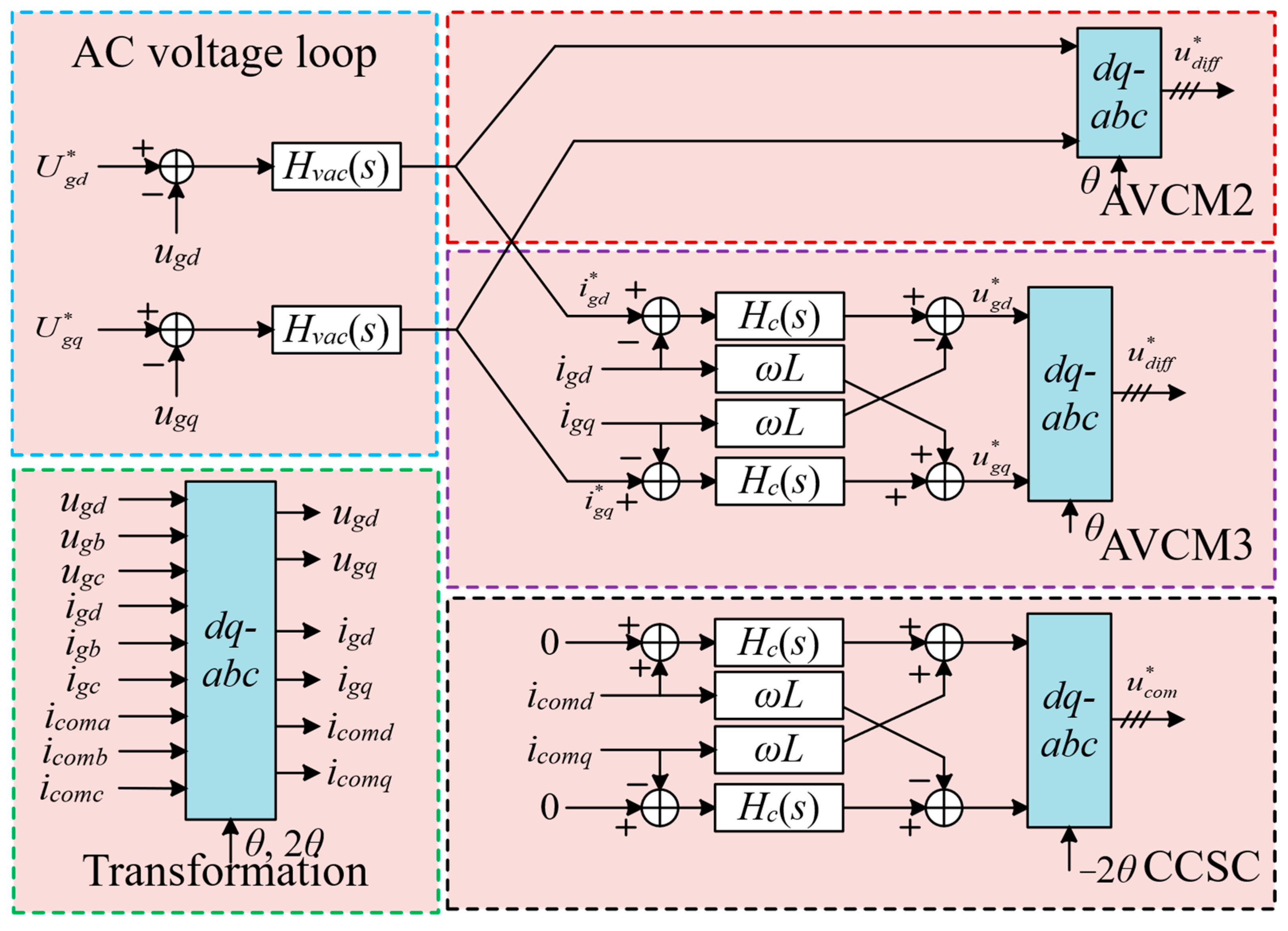
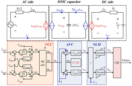
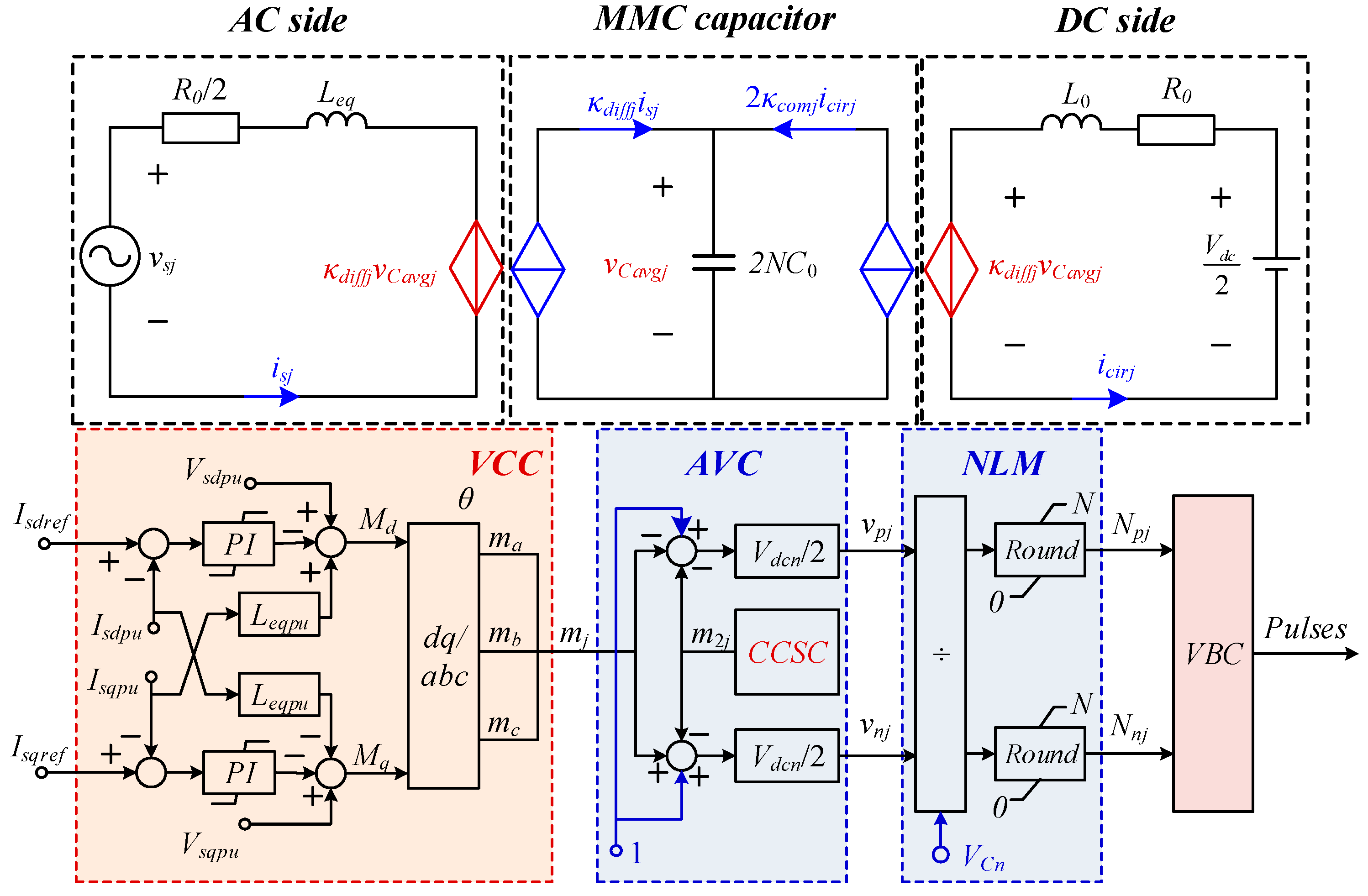
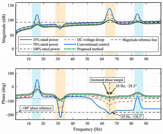
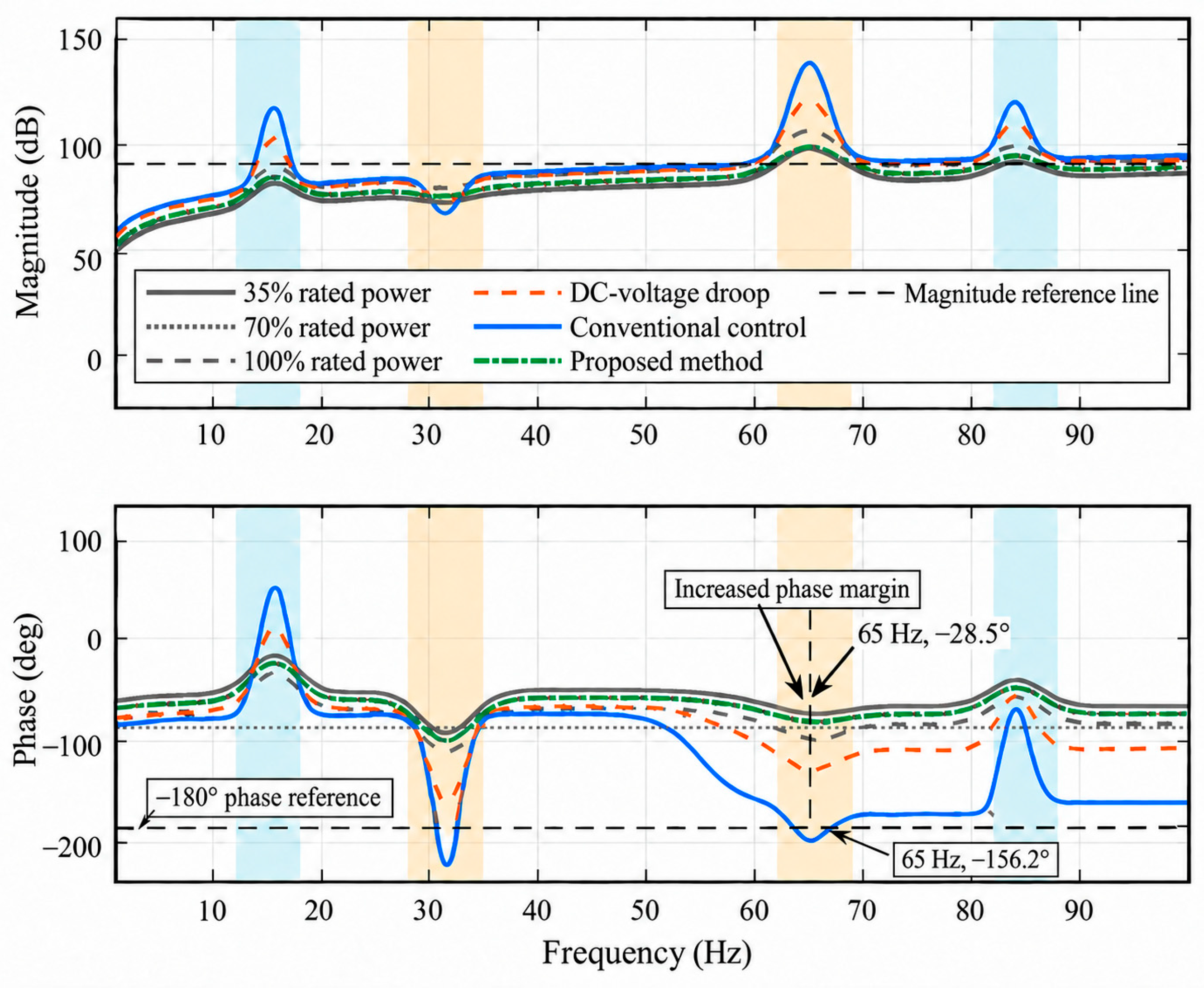
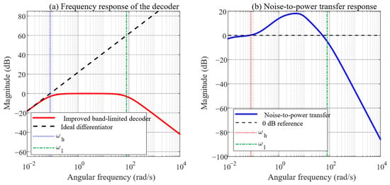
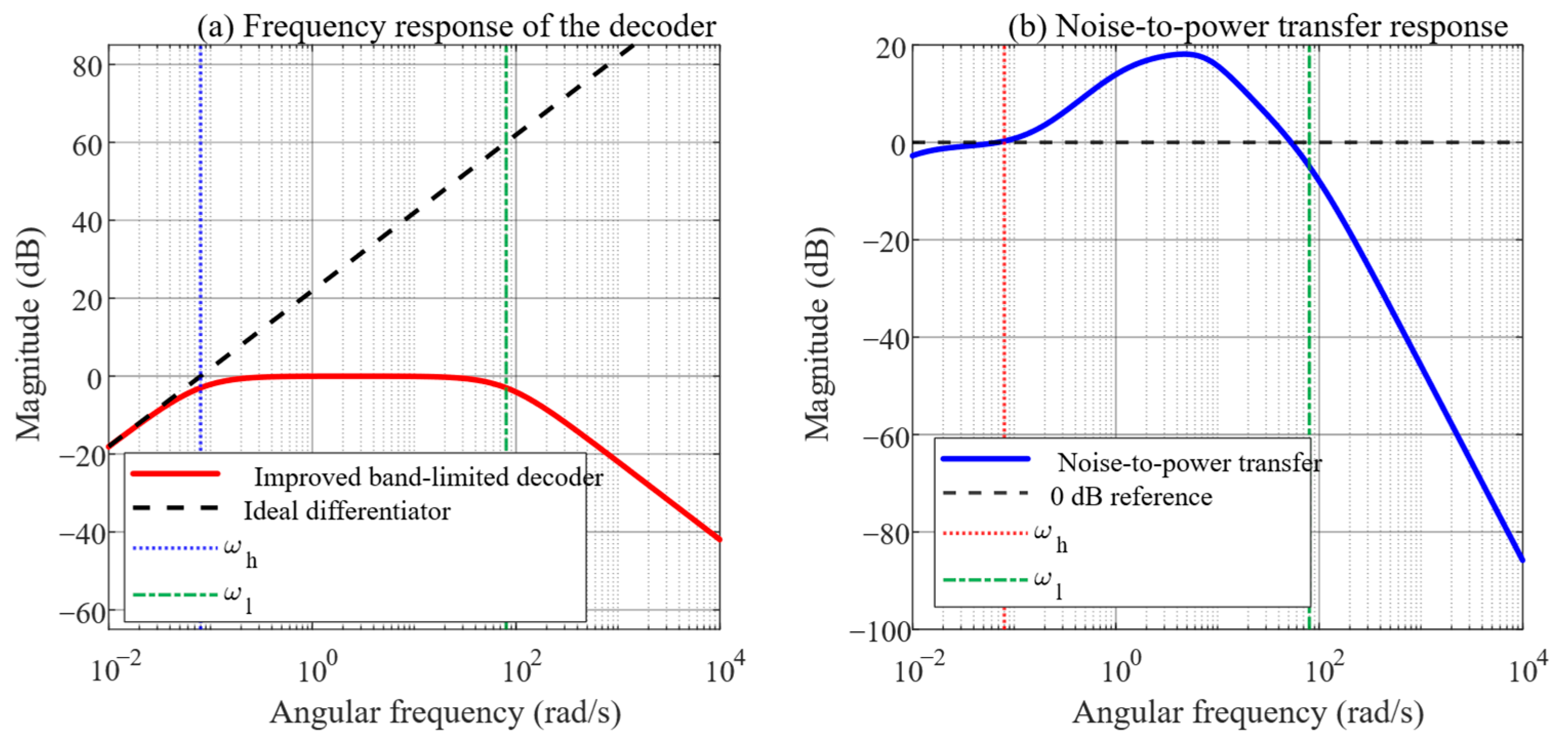
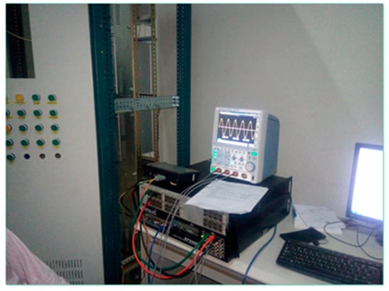
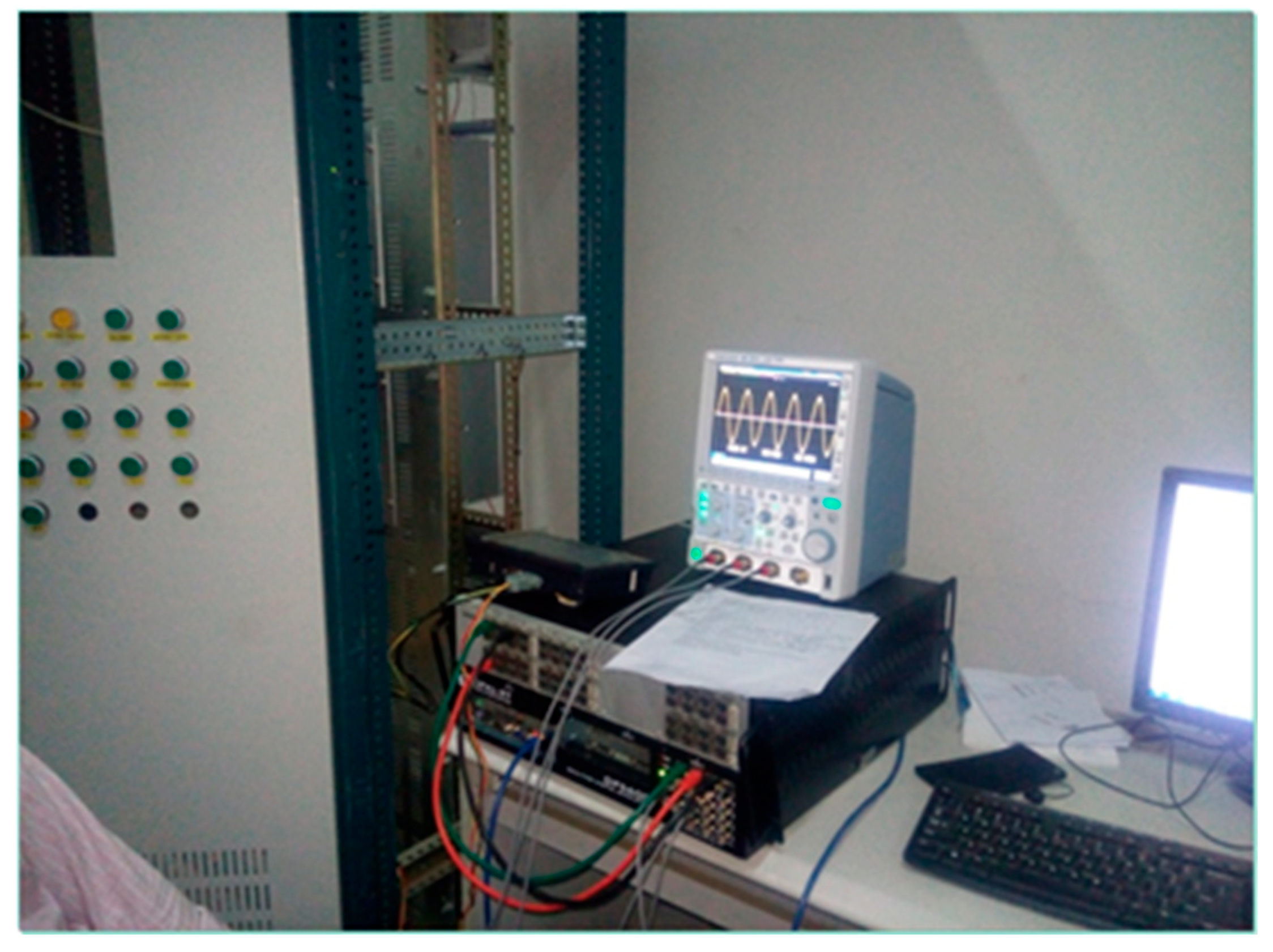
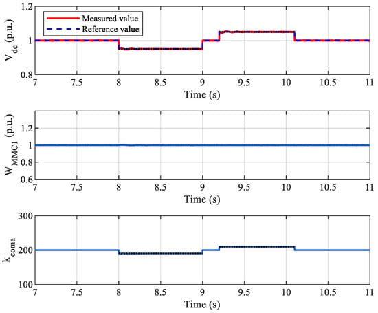
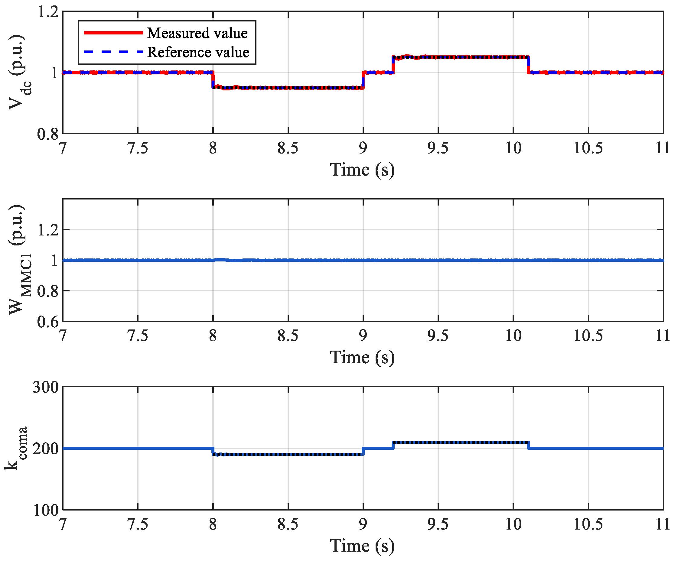
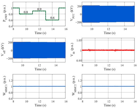
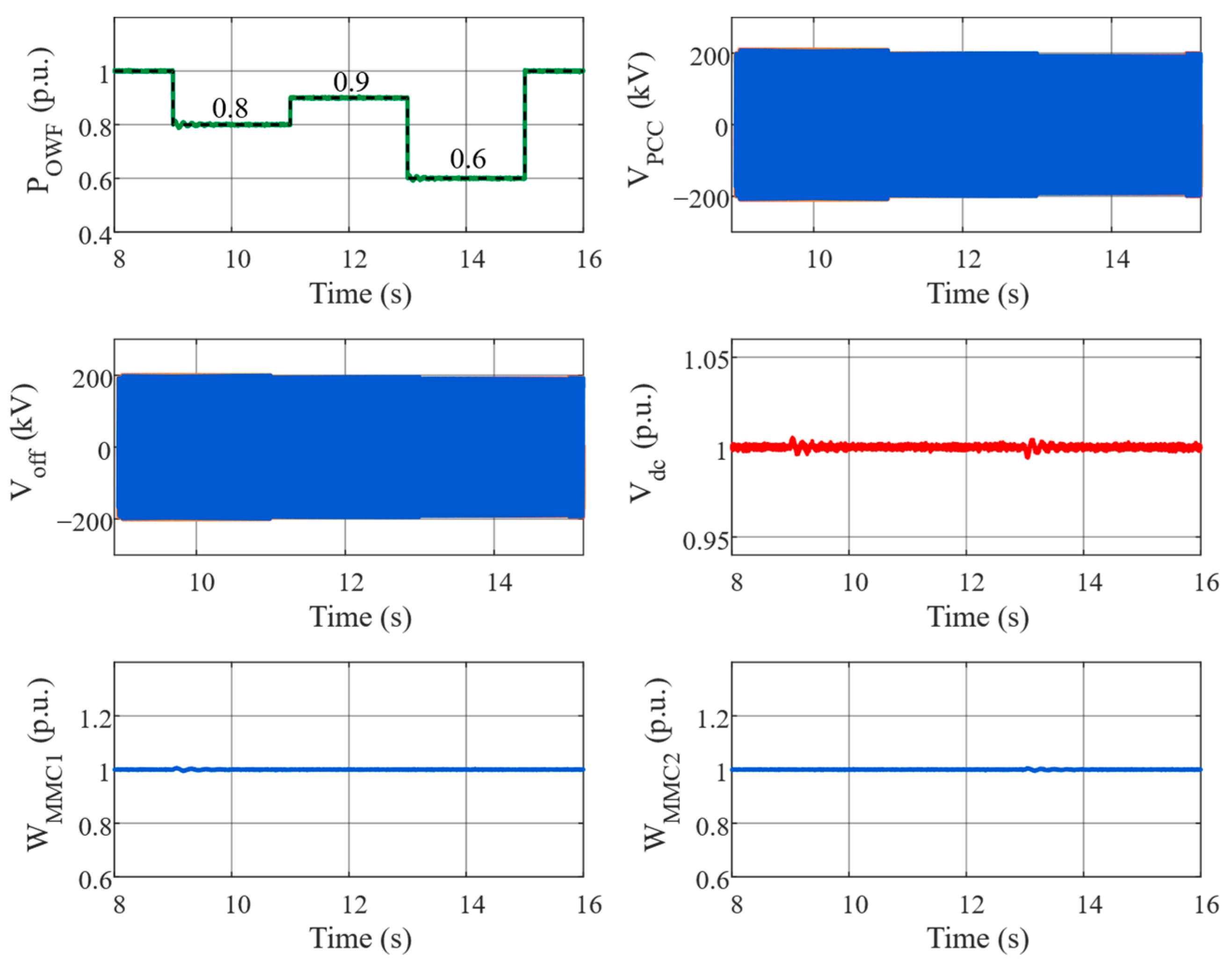
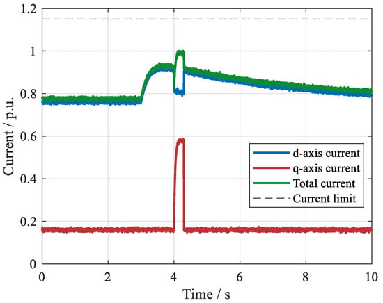
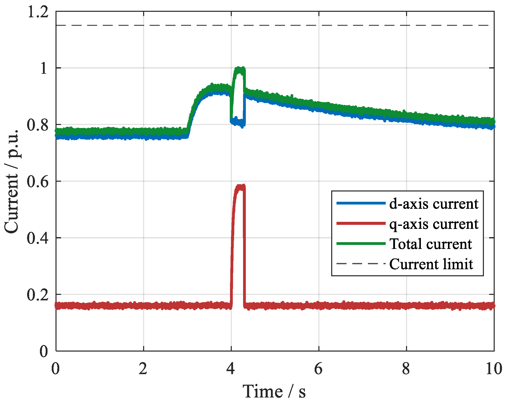
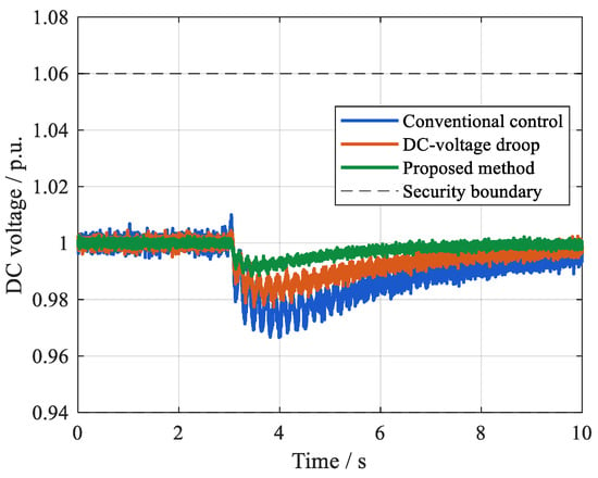
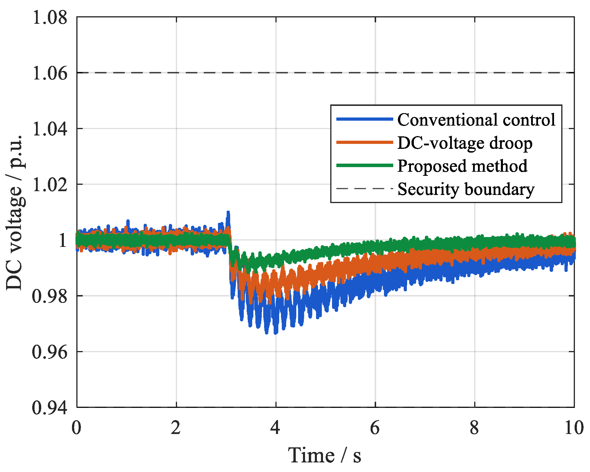
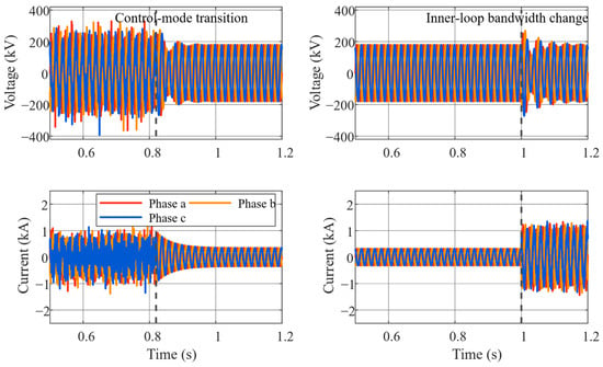

Disclaimer/Publisher’s Note: The statements, opinions and data contained in all publications are solely those of the individual author(s) and contributor(s) and not of MDPI and/or the editor(s). MDPI and/or the editor(s) disclaim responsibility for any injury to people or property resulting from any ideas, methods, instructions or products referred to in the content. |
© 2026 by the authors. Licensee MDPI, Basel, Switzerland. This article is an open access article distributed under the terms and conditions of the Creative Commons Attribution (CC BY) license.