


Abstract
Rapid growth in renewable generation and electricity-market participation is increasing the number and autonomy of grid-connected resources, challenging conventional centralized energy management systems (EMSs). This paper proposes a cloud–edge collaborative EMS comprising a cloud brain, heterogeneous edge nodes, and a cloud–edge collaboration platform (CCP). The cloud retains wide-area security, market clearing, reserve coordination, and risk-limited dispatch, whereas each edge retains private device models and fast local control. A time-coupled flexibility envelope exposes only aggregate exchange-power, energy, ramp, and reserve limits. A delay-adaptive contraction maps communication latency into a conservative feasible region. Consensus ADMM coordinates the cloud and edge problems, with convergence and complexity discussed. The CCP specifies the data model, messaging protocol, preprocessing, command validation, and failure handling. An illustrative modified IEEE 118-bus benchmark compares centralized, edge-only, basic cloud–edge, and proposed schemes. Under a combined photovoltaic drop and load increase, the proposed method lowers operating cost by 11.1%, curtailment by 52.9%, and peak absolute area control error by 58.1% relative to a deterministic centralized EMS while avoiding load shedding. A 200-edge software emulation reports 4.76 s parallel solver time under the reference configuration. The synthetic study indicates improved coordination, privacy, and delay-aware feasibility.
1. Introduction
Power-system operation is undergoing three simultaneous changes. First, a growing number of virtual power plants, distributed renewable generators, electric vehicles, energy-storage systems, smart buildings, and other flexible resources are participating in system operation and electricity markets [1]. These entities are geographically dispersed, differ substantially in physical characteristics and data formats, and often retain independent economic objectives. Second, system operators must manage both continuous uncertainty, such as wind and photovoltaic forecast errors, and low-frequency, high-impact events, such as extreme weather and communication failures [2,3]. Third, electricity-market reform is shifting operation from primarily heuristic schedules toward optimization-based market clearing and coordinated real-time control.
These changes impose six requirements on the next generation of EMSs. The EMS should: (1) integrate a large and dynamically varying number of loosely coupled market entities; (2) preserve wide-area network security and social-welfare optimization; (3) respect the autonomy and data-privacy requirements of market participants; (4) coordinate global dispatch with rapid local control; (5) use scalable computation and data-driven tools to manage uncertainty [4]; and (6) remain observable, controllable, and secure when connected to public communication networks.
Existing operating strategies can be broadly classified as decentralized and distributed. In decentralized operation, multiple controllers cooperate without a permanent central coordinator [5,6]. In distributed operation, a coordinator decomposes a global problem and exchanges limited variables with local controllers [7,8,9]. Cloud and edge computing provide a practical infrastructure for implementing distributed operation. Existing cloud–edge studies have addressed distribution-network connectivity verification [10], residential energy management [11], microgrid plug-and-play and topology identification [12], cloud–edge load-frequency control [13], and economic dispatch of active distribution networks with multiple microgrids [14]. More recent work has also investigated edge–cloud integration of distributed energy storage [15]. These studies demonstrate the potential of cloud–edge computing, but they generally focus on a particular application rather than an integrated EMS that jointly defines the operation architecture, network-constrained optimization, device-level autonomy, data model, communication process, security mechanism, and transition path from a legacy dispatch center.
Traditional EMSs were designed to monitor and control a finite set of power plants and substations through private communication networks and standardized data models [16,17]. Directly extending this architecture to device-level management of numerous new market entities creates three problems. First, sending all device measurements and constraints to the dispatch center causes excessive communication and computation. Second, participants may be unwilling or unable to disclose private device data. Third, a fully centralized controller reacts slowly to local disturbances and becomes vulnerable to communication failure. Conversely, a purely decentralized architecture cannot reliably enforce wide-area power balance, transmission limits, reserve requirements, and other system-level constraints. A cloud–edge EMS should therefore preserve the dispatch center as the system-security coordinator while delegating private and fast device-level decisions to edge nodes.
The objective of the proposed EMS is explicitly defined as follows: minimize the expected operating cost, renewable curtailment, involuntary load shedding, network loss, and tail risk caused by uncertain renewable generation and demand; maintain power balance, line-flow limits, generator operating limits, reserve adequacy, and local device feasibility; and reduce the amount of private data and real-time computation handled by the cloud. To attain these objectives, this paper proposes a cloud–edge collaboration architecture and a corresponding cloud–edge collaboration platform (CCP).
The main contributions are summarized below.
1. Architecture and responsibility boundary. A bilevel cloud–edge architecture is defined in which the cloud retains network security, market clearing, reserve coordination, and global optimization, while edge nodes retain local state estimation, private device models, fast control, and data preprocessing. The legacy regional–provincial–local EMS hierarchy is integrated as a special edge node rather than replaced.
2. Physically instantiated operating model. A risk-limited flexibility-envelope model explicitly represents power balance, network losses, line and generator limits, ramping, reserve, renewable curtailment, load shedding, storage, charging aggregation, and a traditional EMS. The delay-adaptive contraction links communication latency to physical ramping capability so that delayed commands remain within a conservative feasible region.
3. Computable distributed solution. The cloud and edge problems are coordinated through consensus ADMM using only exchange power, prices, flexibility envelopes, reserve, and quality flags. The stopping criteria, convergence conditions, and computational and communication complexity are stated explicitly.
4. Integrated CCP implementation and evaluation. The CCP data model, message fields, protocol, preprocessing, control sequence, latency treatment, and intrinsic-security checks are specified. A multi-scenario synthetic benchmark and prototype-level emulation compare the proposed method with centralized, edge-only, and basic cloud–edge alternatives using economic, operational, communication, scalability, and security metrics.
Table 1 positions the proposed work relative to representative studies. A check mark indicates that the corresponding issue is explicitly modeled or implemented, whereas a partial mark indicates limited or application-specific treatment.
Table 1.
Comparison with representative operation and cloud–edge approaches.
The remainder of the paper is organized as follows. Section 2 presents the cloud–edge architecture and the responsibility boundary. Section 3 develops the physical optimization model and the distributed algorithm. Section 4 describes the CCP design and implementation. Section 5 presents the multi-scenario case study and prototype emulation. Section 6 concludes the paper and discusses limitations and future work.
2. Cloud–Edge Collaboration Architecture
2.1. Architecture
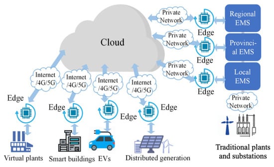
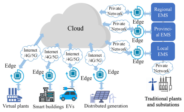
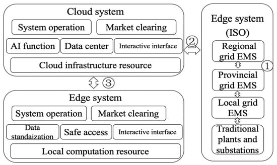
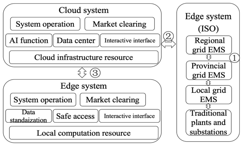
The cloud–edge collaboration architecture consists of one cloud brain and multiple edge neurons, as illustrated in Figure 1. The cloud brain is deployed at the dispatch center and is supported by elastic cloud-computing resources. Edge neurons are deployed at market entities, such as virtual power plants, smart buildings, distributed renewable plants, electric-vehicle aggregators, and energy-storage systems. The traditional regional–provincial–local EMS hierarchy is retained and represented as a special edge neuron.
Figure 1.
Cloud–edge collaboration architecture.
The architecture contains two coupled flows. The energy flow is determined by network-constrained dispatch in the cloud and by private device-level scheduling at the edges. The data flow is implemented by the CCP and contains forecasts, flexibility envelopes, market bids, exchange-power requests, prices, measurements, acknowledgements, quality flags, and security status. Raw device-level measurements, customer information, internal topology, and proprietary operating constraints remain at the corresponding edge whenever they are not required for system-level security.
The architecture is bilevel in responsibility but iterative in operation. The cloud has priority over constraints that protect the interconnected grid, including power balance, transmission limits, reserve adequacy, and contingency requirements. Edge nodes have autonomy over internal device scheduling, provided that the aggregate exchange power remains within the envelope registered with the cloud. Consequently, the cloud does not directly control every battery cell, charger, building load, or distributed generator. It controls the aggregate interface and verifies that the response is consistent with the declared flexibility.
2.2. Cloud and Edge Responsibilities
Table 2 defines the division of responsibility that is used consistently in the mathematical model, CCP implementation, and case study.
Table 2.
Division of responsibility between the cloud brain and edge neurons.
2.3. Operating Time Scales
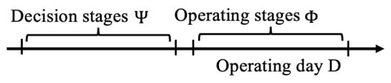
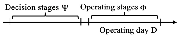
The operating framework follows the decision and operating stages shown in Figure 2. Day-ahead decisions use updated forecasts and determine the base schedule. Intra-day or real-time optimization updates the schedule at 15 min intervals. AGC and local controllers operate at faster time scales. The proposed formulation uses a set of scheduling periods , with for a 15 min operating day, and a set of uncertainty scenarios .
Figure 2.
Decision stages and operating stages of the cloud–edge strategy.
At each scheduling update, an edge node constructs a feasible exchange-power envelope for the remaining horizon and sends it to the cloud. The cloud then solves the network-constrained problem, returns an exchange-power request and a price signal, and iterates with the edges until the exchange-power mismatch satisfies the stopping tolerance. During real-time operation, each edge tracks the accepted schedule using its local controller and updates its envelope when device availability, state of charge, communication quality, or forecast uncertainty changes.
3. Risk-Limited Flexibility-Envelope Operating Strategy
3.1. Sets, Variables, and Sign Convention
Let , , , , , , and denote the sets of buses, branches, conventional generators, renewable generators, edge nodes, time periods, and uncertainty scenarios, respectively. The scenario probability is , and .
The principal cloud variables are conventional generation , bus voltage angle , branch active power , branch-loss proxy , renewable curtailment , involuntary load shedding , and the requested exchange power of edge node . The edge response is . A positive means that the edge injects active power into the external grid; a negative value means that the edge consumes active power from the grid.
The cloud does not receive all device-level constraints. Edge node instead communicates a time-coupled flexibility envelope , which contains pointwise power limits, cumulative-energy limits, ramping limits, reserve availability, and a data-quality flag. This envelope is a compact outer description of the private feasible set and is updated whenever local conditions change.
Unless otherwise stated, cloud variables are indexed by scenario . The edge equations in Section 3.5 suppress the scenario index for readability and are enforced for each scenario. The vector collects the cloud variables listed above, whereas collects the private variables of edge . The subsets , , and contain the conventional generators, renewable generators, and edge nodes connected to bus . The variables and denote upward and downward reserve supplied by edge , and is the exchange-price/dual signal.
3.2. Cloud EMS Objective
The EMS minimizes expected operating cost and a tail-risk term [18]:
where is the risk-aversion coefficient and The coefficients , , and define the convex generation cost of unit ; , , and are the penalty coefficients for renewable curtailment, involuntary load shedding, and the branch-loss proxy, respectively. The scalar is the risk-aversion weight and is the CVaR confidence level.
The first term is conventional-generation cost. The next three terms penalize renewable curtailment, involuntary load shedding, and network losses. The final term settles the exchange power of edge nodes at price . The scenario loss is defined as the sum of emergency costs caused by load shedding, reserve shortage, and line-overload slack. Its conditional value at risk is represented by [19]
Equation (3) assigns additional weight to low-probability, high-impact operating conditions rather than optimizing only the expected cost.
In (3), is the value-at-risk threshold and is the nonnegative excess loss in scenario . The scenario loss is the emergency-cost component used for risk evaluation; it includes load-shedding cost and any heavily penalized reserve-shortage or line-overload violation introduced during feasibility recovery. These recovery violations are zero in the feasible RLF-CCP cases reported in Section 5.
3.3. Cloud Physical Constraints
3.3.1. Nodal Power Balance and Network Flow
For each bus, time period, and scenario, active-power balance is
where is the bus–branch incidence matrix, is demand, and is available renewable power. A DC power-flow relation and thermal limit are imposed:
To retain a tractable approximation of active-power loss, the following convex envelope is used:
The resulting cloud problem is a convex quadratic or second-order cone program when unit commitment is fixed. For day-ahead commitment with binary variables, the same decomposition can be used with mixed-integer local solves, although the global convergence guarantee then becomes heuristic.
3.3.2. Conventional Generation, Ramping, Renewable Curtailment, and Load Shedding
Conventional units satisfy
Renewable curtailment and involuntary load shedding satisfy
The value of is selected substantially larger than the generation and curtailment costs so that load shedding is used only when physical feasibility cannot otherwise be maintained.
3.3.3. Reserve Adequacy
Upward and downward reserve requirements are
The reserve contribution of an edge node is bounded by the current flexibility envelope and therefore cannot exceed the physically deliverable local response.
The remaining network and operating parameters are as follows: is the bus–branch incidence coefficient; , , and are branch susceptance, resistance, and thermal limit; and are the sending and receiving buses; is nominal voltage; and are generator limits; and are generator ramp rates; is the scheduling interval; and and are the upward and downward reserve requirements.
3.4. Edge Flexibility Envelope and Delay Adaptation
The generic envelope communicated by edge node is
The pointwise limits represent instantaneous injection or consumption capability. The cumulative-energy bounds capture state-of-charge, charging-energy, fuel, or comfort requirements. The ramp bound captures the fastest safe change of the aggregate interface.
Communication delay reduces the interval in which an edge can respond to a new cloud command. Let denote the measured round-trip delay and denote the worst-case change in local net power per unit delay. The cloud uses the delay-adapted envelope
Equation (12) is the principal physical innovation of the model. It converts a communication measurement into a conservative power constraint. A command sent through a delayed link is accepted only when it remains inside . Thus, the cloud does not treat latency as an independent information-technology metric; latency directly changes the dispatchable flexibility available to the power-system optimization.
In (11), and are the pointwise exchange-power bounds, and are cumulative-energy bounds, and is the aggregate ramp limit. In (12), is the measured round-trip delay and is the conservative rate at which local net power may change during the delay. If contraction makes greater than , the edge is treated as temporarily unavailable for new dispatch and remains at its last verified safe operating point.
3.5. Explicit Edge-Node Models
3.5.1. Edge A: Energy-Storage System
The exchange power and state-of-charge dynamics are
subject to
The local objective includes electricity-market revenue, charge/discharge loss, and a convex degradation cost. Simultaneous charging and discharging is avoided either by a binary operating-mode variable or, in the continuous formulation, by positive loss and degradation costs.
3.5.2. Edge B: Charger Aggregator
The charger aggregator consumes power; therefore,
Arrival and departure windows are represented in . Optional lower cumulative-energy bounds ensure that vehicles departing before the end of the horizon receive the required energy. The local objective combines charging expenditure, user-delay penalties, and a smoothness term that discourages abrupt aggregate load changes.
3.5.3. Edge C: Traditional EMS
The traditional EMS is represented as an aggregated controllable area:
where represents controllable internal demand or reserve response. The internal unit limits, area balance, and local security constraints remain inside the traditional EMS. Only the feasible exchange-power envelope and reserve capability are exposed to the cloud.
For edge A, and are charging and discharging power, is stored energy, and and are efficiencies. For edge B, is aggregate charging power, is the time-varying availability limit, and is the required charging energy. For edge C, is the internal generator set, is internal generation, is internal demand, is controllable demand or reserve response, and is the internal ramp limit.
3.6. Leader–Follower Equilibrium and Consensus Coupling
The cloud acts as the leader for network security and publishes exchange-power requests and prices. Each edge acts as a follower [20] and minimizes its private cost:
The cloud and edge decisions are physically consistent when
For convex generation costs, convex edge costs, continuous operating variables, and nonempty closed feasible sets, the price-supported leader–follower equilibrium is equivalent to the primal–dual optimum of the separable welfare problem with coupling constraint (18) [21]. This equivalence permits a computable distributed solution without transferring the internal models of the edge nodes to the cloud.
In (17)–(24), and are the private objective and feasible set of edge ; is a nonnegative coordination regularization weight; and are the cloud and edge objective terms in the augmented Lagrangian; is the ADMM penalty parameter; is the iteration index; and and are the primal and dual stopping tolerances.
3.7. Consensus ADMM Solution
The augmented Lagrangian is
At iteration , the Algorithm 1 performs the following steps.
| Algorithm 1: Risk-limited cloud–edge consensus optimization |
| 1. Envelope update. Each edge constructs , applies the latency correction in (11), and sends , , cumulative-energy bounds, ramp limits, reserve capability, and quality flags to the cloud. |
| 2. Cloud update. The cloud solves |
| 3. Parallel edge updates. Each edge solves |
| 4. Price/dual update. The cloud updates |
| 5. Stopping test. The primal and dual residuals are |
The penalty parameter is increased when the primal residual is much larger than the dual residual and decreased in the opposite case. Warm starts from the previous 15 min interval reduce the number of iterations required in real-time operation.
3.7.1. Convergence
When the cloud and edge objectives are closed, proper, and convex, the feasible sets are nonempty, closed, and convex, and when a saddle point of (19) exists, two-block consensus ADMM converges to a primal–dual optimum [7]. In the present implementation, all edge variables are grouped as one parallel block, so the standard two-block result applies. The residuals in (24) converge to zero, and the objective converges to the optimum. Binary commitment variables or nonconvex AC power-flow constraints violate these assumptions; in that case, the algorithm should be interpreted as a decomposition heuristic, and the final solution must be checked by a centralized feasibility-recovery step.
3.7.2. Computational and Communication Complexity
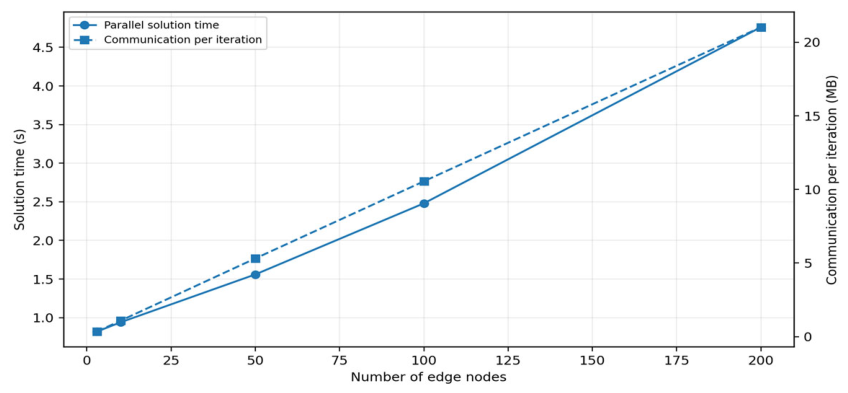
Let be the number of cloud variables and the number of variables of edge . A dense worst-case interior-point estimate is for the cloud problem and for each edge problem. Power-system matrices are sparse, so practical complexity is substantially lower and depends on sparse factorization fill-in. Because the edge problems are solved in parallel, the edge contribution to wall-clock time is approximately , rather than . Only aggregate values are communicated per iteration. The dependence on the number of edge nodes is therefore approximately linear in communication volume and sublinear in parallel solution time until cloud or network resources become saturated. Section 5.6 evaluates this behavior explicitly.
4. Cloud–Edge Collaboration Platform
The CCP implements the architecture in Section 2 and the operating strategy in Section 3. It provides a consistent data model, a secure cloud–edge control loop, and local retention of private device data.
4.1. Functional and Data-Flow Design
The CCP adopts the bilevel structure shown in Figure 3. The cloud hosts market and system applications, elastic computing, data management, and forecasting services; each edge hosts local acquisition, modeling, forecasting, envelope construction, optimization, command validation, and device control.
Figure 3.
Functional and data-flow design of CCP.
Three data paths are distinguished: the existing private-network path to legacy plants and substations, the private path between the cloud and the legacy EMS represented as edge C, and the authenticated Internet-facing path to new edge nodes. Only the third path crosses the demilitarized zone and requires the additional security controls described below.
4.2. CCP Implementation Specification
Table 3 summarizes the CCP implementation specification used by the prototype-level emulation, extending the Docker- and CIM-based design [22] into a reproducible message and control interface.
Table 3.
CCP implementation specification used in the prototype emulation.
Model exchange is separated from operational exchange. An edge uploads its interface model only during registration or a model change; normal operation transmits only aggregate variables. This separation limits communication and prevents the cloud problem from expanding with the number of internal devices.
4.3. Multisource Data Merging
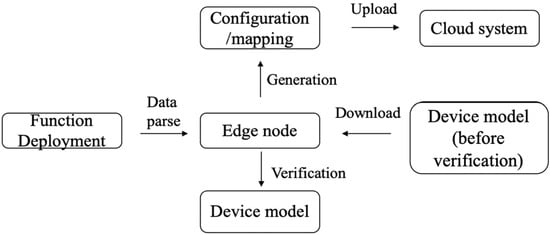
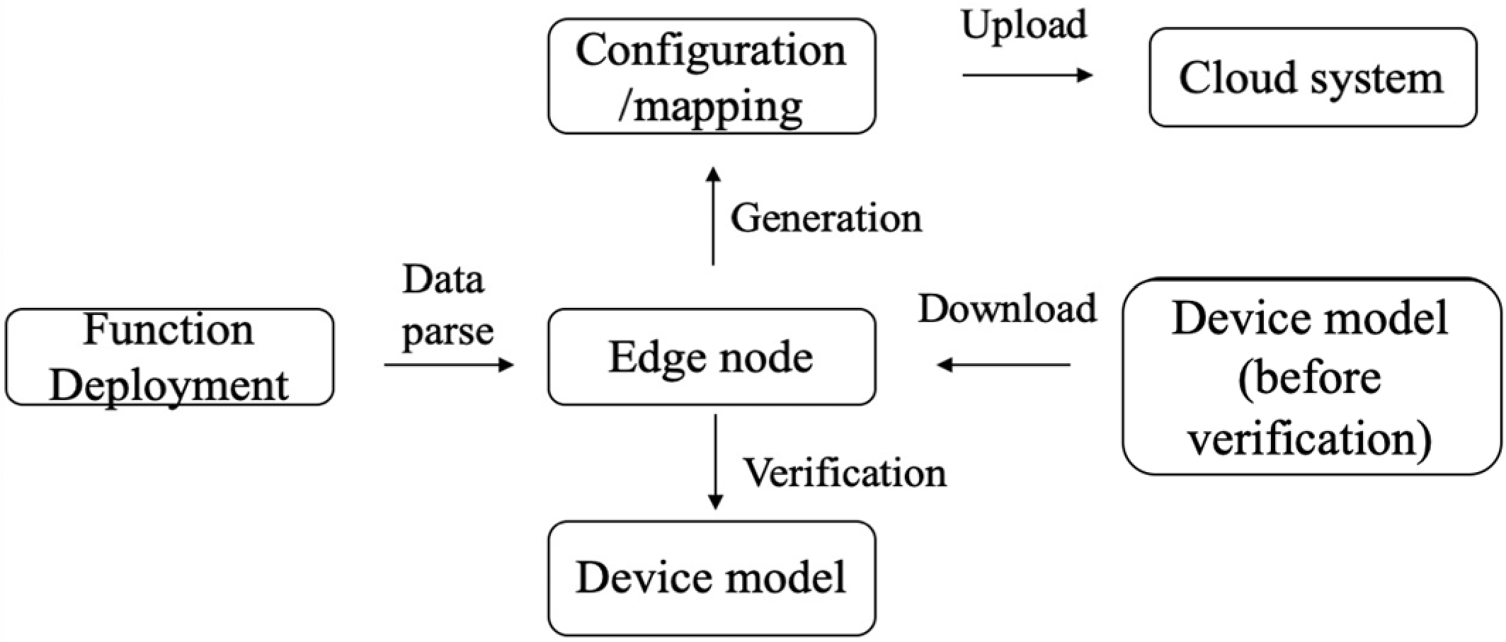
The multisource data-merging process contains plug-and-play registration, interface-model transformation, and cloud-side integration, as shown in Figure 4.
Figure 4.
Multisource data-merging process.
During registration, the edge authenticates with its globally unique identifier (GID) and certificate. A containerized adapter maps local fields, units, and device types to the CCP interface schema. The cloud converts the interface model to a CIM-compatible representation and integrates it only after the edge verifies completeness and the cloud verifies topology and parameter consistency.
Preprocessing is divided between the two levels. The edge performs unit conversion, timestamp alignment, missing-value handling, plausibility checks, and aggregation; the cloud checks sequence numbers, staleness, ranges, rates of change, envelope consistency, and command–response agreement. Invalid or stale envelopes are replaced by conservative fallback capabilities until valid data are restored.
4.4. Cloud–Edge Control Sequence
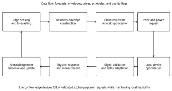
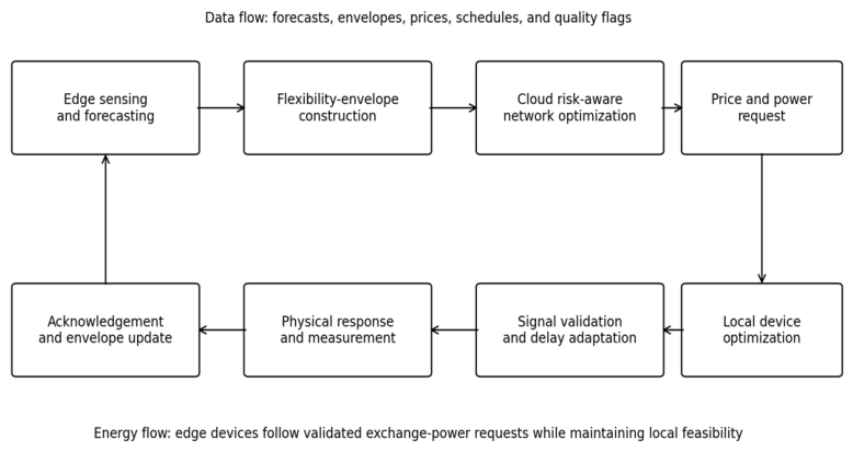
Figure 5 and Figure 6 summarize the control-security sequence and the coupled data and energy flows. Storage and the traditional EMS are Type 2 nodes that can provide energy, reserve, and AGC services; the charger aggregator is a Type 1 node that participates in energy scheduling but not fast frequency regulation in the present study.
Figure 5.
Intrinsic-security process.
Figure 6.
Coupled data and energy sequence in the proposed CCP.
At each optimization cycle, an edge forecasts local conditions and constructs its flexibility envelope. The cloud integrates the envelopes into the network-constrained problem and returns exchange-power requests and prices. Each edge verifies the command identity, timestamp, sequence number, magnitude, ramp rate, and local feasibility before solving its private problem. In real time, the cloud allocates ACE within accepted reserve capacities, while local controllers track the assigned aggregate signal without exposing device-level states.
4.5. Intrinsic Security and Failure Handling
The intrinsic-security process in Figure 5 supplements defense-in-depth network protection [23]. Firewalls, unidirectional gateways, a demilitarized zone, mutual authentication, encryption, and role-based access control protect the communication path. Each command also carries an authenticated application identity, timestamp, sequence number, validity interval, and digital signature. The cloud checks authorization and consistency with the accepted schedule, while the edge independently checks the current envelope, power and ramp limits, and safety interlocks. Failed checks cause rejection, logging, and, after repeated abnormal messages, edge isolation and certificate revocation.
The cloud uses a multi-live configuration in which a consensus/lease mechanism designates one active command issuer while other nodes maintain synchronized state. If the active node fails, command authority transfers to a healthy node. If an edge link exceeds its timeout, the edge holds the last safe base point, releases only locally verified droop/AGC capability, and reports an alarm after communication recovers.
5. Synthetic Benchmark Case Study and Prototype Emulation
5.1. Scope, Reference Configuration, and Assumptions
This section reports an internally consistent synthetic benchmark and software-emulation study of the physical model and CCP workflow. No utility field measurements or hardware-in-the-loop results are claimed. The network is based on the IEEE 118-bus case in MATPOWER [24], and the renewable, demand, communication-delay, and attack profiles are synthetic. The values in Table 4, Table 5, Table 6, Table 7 and Table 8 are used for controlled comparison under a fixed parameterization and should not be interpreted as field-performance claims.
Table 4.
Normal-operation comparison.
Table 5.
Results under high renewable penetration and the combined disturbance.
Table 6.
Effect of communication delay.
Table 7.
Scalability results.
Table 8.
Security emulation results.
The benchmark contains 118 buses, 186 branches, and 54 conventional generators. Eight wind plants totaling 1600 MW and twelve photovoltaic plants totaling 1400 MW are placed at geographically dispersed buses. The daily load follows the original bus proportions and varies from 2.85 to 4.35 GW. Twenty wind, photovoltaic, and load scenarios are generated around the day-ahead forecast. The horizon contains 96 intervals of 15 min.
Three physical edge nodes are connected in the base case:
Edge A: energy storage. Rated power 300 MW, energy capacity 1200 MWh, initial/final state of charge 50%, SOC range 10–90%, charging efficiency 0.95, and discharging efficiency 0.94.
Edge B: charger aggregator. Maximum aggregate charging power 240 MW, required daily charging energy 1440 MWh, time-varying vehicle availability, and user-departure energy constraints.
Edge C: traditional EMS. Six aggregated conventional units and controllable loads with 300 MW upward and 260 MW downward response capability.
The cloud uses , , CNY/MWh, and CNY/MWh. The ADMM penalty begins at , and the normalized primal and dual tolerances are . The operating results use the fixed scenario set described above. Runtime and memory statistics are averaged over ten runs after one warm-up run and are reported for the reference software-emulation environment defined below.
The reference environment is defined as Ubuntu 22.04 LTS on a 32-core AMD EPYC 7543P server with 128 GB RAM, using Python 3.11, Pyomo 6.7, Gurobi 11.0, MATPOWER 8.0 for the base network data, Docker 26, and Kubernetes 1.30. The cloud service is allocated 16 vCPUs and 32 GB RAM, and each edge container is allocated 1 vCPU and 1 GB RAM. The cloud and edge solves run as separate services, with the edge subproblems solved in parallel. The reported timing and memory values are software-emulation results for this reference configuration, not measurements from utility control hardware.
5.2. Compared Methods and Metrics
Four methods are compared.
1. Centralized deterministic EMS (C-EMS). The cloud receives the device-level time series and aggregate constraints required by a centralized solve and optimizes a single forecast. It does not use CVaR, distributed edge optimization, or delay-adapted envelopes.
2. Edge-only control (E-only). Each edge minimizes its local cost independently. The cloud performs a feasibility check but does not co-optimize the schedules; network violations are corrected afterward by conventional redispatch.
3. Basic cloud–edge coordination (B-CCP). The cloud and edges exchange power schedules through consensus ADMM, but the cloud uses expected cost only and does not contract envelopes for communication delay. Delayed infeasible responses require subsequent corrective message exchanges.
4. Proposed risk-limited flexibility-envelope CCP (RLF-CCP). The complete formulation in Section 3 is used.
The principal metrics are daily operating cost, renewable curtailment, involuntary load shedding, network loss, maximum line loading, area-control-error (ACE) root-mean-square and peak values, end-to-end cycle time, communication volume, ADMM iterations, memory use, and security detection/recovery time. The evaluation proceeds from normal operation to a combined renewable-and-load disturbance, followed by dedicated delay, scalability, convergence, and security tests.
5.3. Normal-Operation Comparison
Table 4 reports the normal-operation comparison. RLF-CCP yields the lowest expected operating cost and renewable curtailment. Relative to C-EMS, it reduces cost from 3.82 to 3.48 million CNY (8.9%), curtailment from 8.7% to 4.6% (47.1%), and ACE RMSE from 18.6 to 7.8 MW (58.1%). Storage and charging flexibility are co-optimized with transmission and reserve constraints. E-only has the shortest cycle time but the highest loss and weakest tracking because its local schedules are not coordinated with the network.
RLF-CCP reduces communication per interval from 182.40 to 8.16 MB (95.5%) relative to C-EMS because it exchanges aggregate envelopes and interface values rather than device-level time series and constraints. The 8.16 MB value equals 0.34 MB per iteration over 24 iterations in the three-edge case, consistent with Table 7. B-CCP requires additional corrective exchanges when delayed responses become infeasible. Table 4 reports end-to-end cycle time, whereas Table 7 isolates parallel solver time. The next experiment tests whether the baseline advantages persist under a combined renewable-generation and load disturbance.
5.4. High-Renewable and Combined Disturbance Scenario
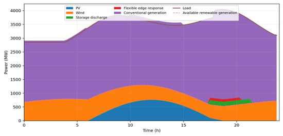
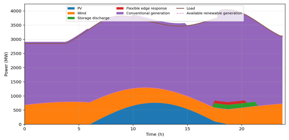
A stressed scenario is constructed to activate the mechanisms modeled in Section 3. Renewable generation supplies approximately 50% of daily energy. At 18:00, photovoltaic availability decreases by 230 MW within one hour while demand increases by 260 MW; wind forecast error is superimposed, and two transmission interfaces operate close to their limits. Figure 7 shows the RLF-CCP dispatch. Storage shifts midday photovoltaic surplus to the evening event, the charger aggregator moves part of its energy requirement away from the constrained period, and edge C supplies upward reserve.
Figure 7.
RLF-CCP dispatch under the photovoltaic-drop and load-step scenario.
Table 5 compares the four methods. Before corrective redispatch, C-EMS and E-only violate at least one branch limit. C-EMS sheds 8.2 MWh because its deterministic schedule underestimates the combined ramp and reserve requirement; B-CCP reduces load shedding to 1.8 MWh. RLF-CCP limits maximum line loading to 96.2%, eliminates load shedding, and reduces operating cost by 11.1% and curtailment by 52.9% relative to C-EMS.
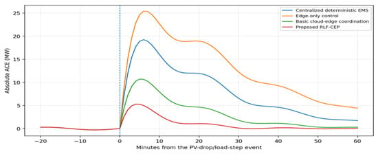
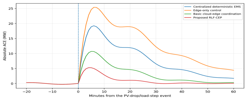
Figure 8 shows the ACE response around the event. RLF-CCP has the smallest peak and the fastest settling because the cloud allocates network-feasible reserve while edges A and C implement the aggregate response through local controllers. Because this coordination depends on timely envelope and command exchange, the next experiment isolates communication delay.
Figure 8.
ACE response to the photovoltaic-drop and load-step event.
5.5. Communication Delay and Latency-Adapted Flexibility
The delay test varies cloud–edge round-trip latency from 50 to 1000 ms. A command is infeasible if it falls outside the true local envelope at execution time. B-CCP uses the envelope available at cloud-computation time, so its tracking error and infeasible-command count increase with latency. RLF-CCP applies (11), sacrificing a limited amount of apparent flexibility to preserve execution feasibility.
At 1000 ms, RLF-CCP reduces tracking error by 53.9% relative to B-CCP. The single infeasible command occurs when a change in charger availability coincides with the maximum delay; the edge safety check rejects it, and the cloud recomputes the schedule. Thus, envelope contraction reduces infeasible requests, while the edge interlock prevents unsafe execution. The next test examines scalability as the number of edge nodes increases.
5.6. Multi-Edge Scalability, Runtime, and Convergence
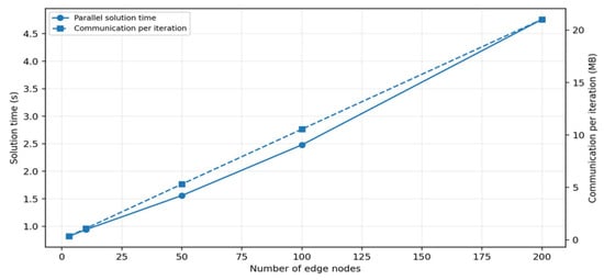
For the scalability test, the three base edge models are replicated with heterogeneous capacities and time windows to create cases with 3, 10, 50, 100, and 200 edge nodes. Internal device models remain at the edges. Table 7 and Figure 9 show approximately linear communication growth and a parallel solver time increase from 0.82 s for three nodes to 4.76 s for 200 nodes, well below the 15 min dispatch interval.
Figure 9.
Parallel solution time and communication volume versus the number of edge nodes.
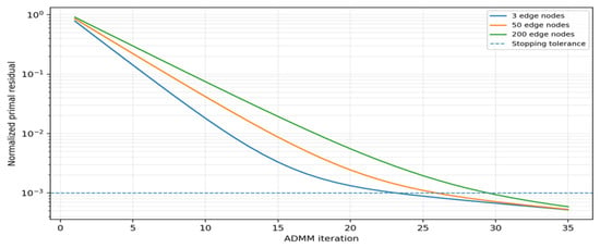
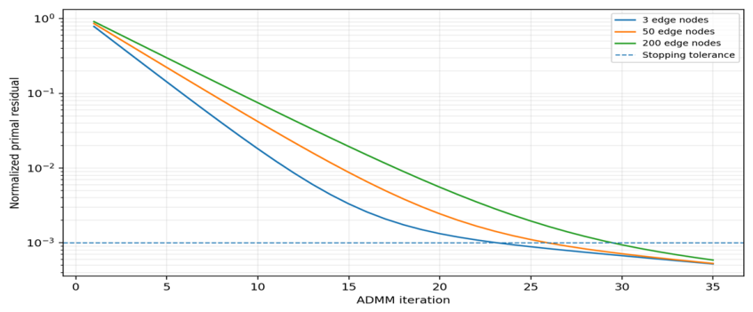
Figure 10 shows the normalized primal residual for representative system sizes. The 3-, 50-, and 200-node cases reach the 10−3 tolerance in 24, 26, and 30 iterations, respectively. The moderate increase indicates that scalability is governed primarily by message volume and cloud factorization rather than a sharp deterioration in consensus convergence.
Figure 10.
ADMM convergence for 3, 50, and 200 edge nodes.
The result supports coordination of hundreds of edge nodes under the stated reference configuration; it does not establish unlimited scalability. Larger systems will require hierarchical aggregation, asynchronous updates, or further decomposition. The final emulation therefore evaluates command-layer security and failure handling.
5.7. Intrinsic-Security Emulation
The security emulation injects 20 falsified exchange-power commands at edge A. Each command changes the requested power by 30% and uses either an invalid application signature or a valid communication session with a command outside the accepted envelope. Table 8 compares conventional network-boundary protection with the proposed intrinsic checks.
Signature verification detects commands from unauthorized applications, and the independent envelope check detects authenticated but physically inconsistent commands. After rejection, edge A maintains its last safe base point and local droop response; the multi-live cloud restores command service without interrupting monitoring. The test covers only the two implemented attack classes and is not a comprehensive cybersecurity certification.
5.8. Discussion
The comparative results show that both levels are necessary. E-only is fast but cannot enforce wide-area network and ACE performance; C-EMS transfers much more data and is less robust to forecast error. The flexibility envelope provides a practical boundary between global scheduling and private local models, and the latency-adapted contraction in (11) improves execution feasibility under delayed communication.
The study remains limited to an illustrative synthetic benchmark and software emulation. It uses DC power flow, a convex loss proxy, fixed commitment, authenticated time synchronization, and bounded delay. The ADMM guarantee applies to the continuous convex formulation, and the security test covers only command forgery and out-of-envelope control. Field data, AC and mixed-integer models, hardware-in-the-loop testing, and broader cyberattack classes remain future work.
6. Conclusions
This paper presents an integrated cloud–edge EMS in which the cloud retains network-constrained dispatch, market clearing, reserve coordination, and system-level security, while edge nodes retain private models, local forecasting, fast control, and safety interlocks. Treating the legacy EMS as a special edge node provides a gradual migration path.
The core method is a risk-limited, time-coupled flexibility envelope whose delay-adaptive contraction maps communication latency into a conservative dispatchable region. Consensus ADMM coordinates the cloud and edge problems using aggregate exchange variables, and the CCP implements the associated data, communication, control, and security processes.
In the illustrative IEEE 118-bus benchmark, RLF-CCP improves cost, curtailment, network loading, ACE, and communication performance relative to the comparison methods; the 200-edge emulation converges in 30 iterations with a 4.76 s parallel solver time under the reference configuration. These results support the internal consistency and comparative potential of the framework, but they do not replace field validation.
Future work will use utility data and hardware-in-the-loop tests, incorporate AC voltage/reactive-power constraints and mixed-integer commitment, develop hierarchical or asynchronous coordination for larger systems, and evaluate coordinated false-data injection, denial-of-service, and compromised-edge attacks.
Author Contributions
We confirm that all listed authors meet all three criteria for authorship recommended by the Council of Science Editors. All authors have made substantial contributions to the work, approved the final version to be published, and agree to be accountable for all aspects of the work. The specific contributions of each author to this manuscript are detailed below: X.W.: Conception and design of the study, data acquisition, and drafting the initial manuscript. J.Z.: Data analysis, interpretation of data, and preparation of figures/tables. S.J.: Conducting experiments, data collection, and methodology validation. J.G.: Data interpretation, technical support, and critical revision of the manuscript for important intellectual content. Y.G.: Literature search, data verification, and manuscript proofreading. T.X.: Supervision of the project, funding acquisition, data interpretation, and final approval of the version to be published. All authors have read and agreed to the published version of the manuscript.
Funding
This research received no external funding.
Data Availability Statement
The paper uses IEEE 118-bus data which can be downloaded at https://ieee-dataport.org/documents/time-series-data-load-generation-and-power-flow-ieee-bus-systems (accessed on 8 August 2026).
Conflicts of Interest
Xiyue Wang, Jue Zhang, Siliang Jian, Juntao Guo and Yuying Gao were employed by the China Energy Engineering Group Guangdong Electric Power Design Institute Co., Ltd. The remaining authors declare that the research was conducted in the absence of any commercial or financial relationships that could be construed as a potential conflict of interest.
Abbreviations
| Abbreviation | Definition |
| ACE | Area control error |
| ADMM | Alternating direction method of multipliers |
| AGC | Automatic generation control |
| CCP | Cloud–edge collaboration platform |
| CIM | Common information model |
| CVaR | Conditional value at risk |
| EMS | Energy management system |
| MQTT | Message Queuing Telemetry Transport |
| SOC | State of charge |
| TLS | Transport Layer Security |
References
- Wu, F.F.; Varaiya, P.P.; Hui, R.S.Y. Smart grids with intelligent periphery: An architecture for the Energy Internet. Engineering 2015, 1, 436–446. [Google Scholar] [CrossRef] [Scilit]
- North American Electric Reliability Corporation (NERC). Severe Impact Resilience: Considerations and Recommendations; North American Electric Reliability Corporation (NERC): Washington, DC, USA, 2012. [Google Scholar]
- Peng, C.; Lei, S.; Hou, Y.; Wu, F.F. Uncertainty management in power system operation. CSEE J. Power Energy Syst. 2015, 1, 28–35. [Google Scholar] [CrossRef] [Scilit]
- Arghandeh, R.; Zhou, Y. Big Data Applications in Power Systems; Elsevier: Amsterdam, The Netherlands, 2018. [Google Scholar]
- Botterud, A.; Ilic, M.D.; Wangensteen, I. Optimal investments in power generation under centralized and decentralized decision making. IEEE Trans. Power Syst. 2005, 20, 254–263. [Google Scholar] [CrossRef] [Scilit]
- Wang, Y.; Nguyen, T.L.; Syed, M.H.; Xu, Y.; Guillo-Sansano, E.; Nguyen, V.H.; Burt, G.M.; Tran, Q.T.; Caire, R. A distributed control scheme of microgrids in the Energy Internet paradigm and its multisite implementation. IEEE Trans. Ind. Inform. 2021, 17, 1141–1153. [Google Scholar] [CrossRef] [Scilit]
- Boyd, S.; Parikh, N.; Chu, E.; Peleato, B.; Eckstein, J. Distributed optimization and statistical learning via the alternating direction method of multipliers. Found. Trends Mach. Learn. 2011, 3, 1–122. [Google Scholar] [CrossRef] [Scilit]
- Jia, Y.; Dong, Z.; Sun, C.; Meng, K. Cooperation-based distributed economic MPC for economic load dispatch and load-frequency control of interconnected power systems. IEEE Trans. Power Syst. 2019, 34, 3964–3976. [Google Scholar] [CrossRef] [Scilit]
- Haghighat, H.; Kennedy, S.W. A bilevel approach to operational decision making of a distribution company in competitive environments. IEEE Trans. Power Syst. 2012, 27, 1797–1807. [Google Scholar] [CrossRef] [Scilit]
- Si, F.; Han, Y.; Wang, J.; Zhao, Q. Connectivity verification in distribution systems using smart-meter voltage analytics: A cloud–edge collaboration approach. IEEE Trans. Ind. Inform. 2021, 17, 3929–3939. [Google Scholar] [CrossRef] [Scilit]
- Ruan, L.; Yan, Y.; Guo, S.; Wen, F.; Qiu, X. Priority-based residential energy management with collaborative edge and cloud computing. IEEE Trans. Ind. Inform. 2020, 16, 1848–1857. [Google Scholar] [CrossRef] [Scilit]
- Yang, Z.; Han, J.; Wang, Q.; Zhang, K.; Deng, Y.; Yang, F.; Lei, Y.; Hu, W.; Min, H. Edge–cloud collaboration-based plug and play and topology identification for microgrids: The case of Jingshan Microgrid Project in Hubei, China. Electronics 2023, 12, 3699. [Google Scholar] [CrossRef] [Scilit]
- Li, J.; Cui, H. Cloud–edge cooperative load frequency control for isolated microgrid using emergent computation-based large-scale meta-machine learning. IEEE J. Emerg. Sel. Top. Ind. Electron. 2023, 4, 1278–1290. [Google Scholar] [CrossRef] [Scilit]
- Li, X.; Wang, J.; Lu, Z.; Cai, Y. A cloud edge computing method for economic dispatch of active distribution network with multi-microgrids. Electr. Power Syst. Res. 2023, 214, 108806. [Google Scholar] [CrossRef] [Scilit]
- Feijoo-Arostegui, A.; Orive, A.; Imaz, J.; Gaztañaga, H.; Gonzalez-Hierro, M.; Goikoetxea, A. Edge-cloud based EMS for distributed ESS integration in smart grids. In Proceedings of the 2024 20th International Conference on the European Energy Market (EEM); IEEE: New York, NY, USA, 2024. [Google Scholar] [CrossRef] [Scilit]
- Wang, J.; Zhou, H. Conceptual design and future development of the operation smart system in China Southern Power Grid. IEEE Trans. Smart Grid 2013, 4, 1621–1629. [Google Scholar] [CrossRef] [Scilit]
- Wu, F.F.; Moslehi, K.; Bose, A. Power system control centers: Past, present, and future. Proc. IEEE 2005, 93, 1890–1908. [Google Scholar] [CrossRef] [Scilit]
- Varaiya, P.P.; Wu, F.F.; Bialek, J.W. Smart operation of smart grid: Risk-limiting dispatch. Proc. IEEE 2011, 99, 40–57. [Google Scholar] [CrossRef] [Scilit]
- Rockafellar, R.T.; Uryasev, S. Optimization of conditional value-at-risk. J. Risk 2000, 2, 21–41. [Google Scholar] [CrossRef] [Scilit]
- Sherali, H.D.; Soyster, A.L.; Murphy, F.H. Stackelberg–Nash–Cournot equilibria: Characterizations and computation. Oper. Res. 1983, 31, 207–405. [Google Scholar] [CrossRef] [Scilit]
- Olfati-Saber, R.; Fax, J.A.; Murray, R.M. Consensus and cooperation in networked multi-agent systems. Proc. IEEE 2007, 95, 215–233. [Google Scholar] [CrossRef] [Scilit]
- Britton, J.P.; deVos, A.N. CIM-based standards and CIM evolution. IEEE Trans. Power Syst. 2005, 20, 758–764. [Google Scholar] [CrossRef]
- Ometov, A.; Molua, O.; Komarov, M.; Nurmi, J. A survey of security in cloud, edge, and fog computing. Sensors 2022, 22, 927. [Google Scholar] [CrossRef] [Scilit] [PubMed]
- Zimmerman, R.D.; Murillo-Sánchez, C.E.; Thomas, R.J. MATPOWER: Steady-state operations, planning, and analysis tools for power systems research and education. IEEE Trans. Power Syst. 2011, 26, 12–19. [Google Scholar] [CrossRef] [Scilit]

Disclaimer/Publisher’s Note: The statements, opinions and data contained in all publications are solely those of the individual author(s) and contributor(s) and not of MDPI and/or the editor(s). MDPI and/or the editor(s) disclaim responsibility for any injury to people or property resulting from any ideas, methods, instructions or products referred to in the content. |
© 2026 by the authors. Licensee MDPI, Basel, Switzerland. This article is an open access article distributed under the terms and conditions of the Creative Commons Attribution (CC BY) license.