


Abstract
With the increasing proportion of power electronic devices in multi-energy microgrid cluster systems, the inertia level of the system continues to decrease, posing severe challenges to the control of system frequency and voltage stability. To improve the frequency and voltage stability of multi-energy microgrid cluster systems, this paper proposes an event-triggered multi-energy microgrid control method to enhance voltage stability. Firstly, this paper analyzes the reactive power and voltage characteristics of multi-energy systems, and constructs stability control models for multi-energy microgrids considering gas network response and thermal network inertia. Aiming at studying the lagging response characteristic of the gas network, a coupling model including the dynamic characteristics of natural gas pressure regulating stations and gas pipelines is established to reveal the transmission mechanism of gas network pressure fluctuations on the output of distributed power sources. Secondly, focusing on the thermal network inertia, the buffering effect of thermal inertia on the power balance of the power grid is clarified by quantifying the heat storage capacity of the thermal pipelines. Then, for voltage control, an event-triggered mechanism based on model prediction is established to adaptively adjust the update timing of control commands, achieving rapid correction of voltage deviations. Finally, for frequency control, a multi-time-scale response framework is constructed, utilizing the millisecond-level response of energy storage systems, the medium-term support of gas turbines, and the long-term buffering of thermal network inertia to form a frequency stability system covering the entire disturbance cycle.
1. Introduction
With the gradual increase in the proportion of renewable energy power generation, new challenges have been brought to the stable operation of multi-energy microgrids. In order to improve the stability of the frequency and voltage of the power subsystem in a multi-energy microgrid, Reference [1] proposed a hierarchical voltage and frequency control framework for the peak and non-peak periods of load power consumption to improve the resilience of the multi-energy microgrid. A double-loop control mechanism is used to maintain voltage and frequency during off-peak hours. On this basis, virtual inertia control is carried out to provide additional inertia for the system to reduce the abrupt change in the frequency transient. The secondary control strategy combines priority-based constant-temperature controlled-load intelligent management considering the customer’s thermal comfort. Heating and cooling aggregation control based on deep learning is used to reduce the frequency deviation and adjust the overall energy consumption during peak hours. As an important flexible resource, energy storage has attracted more and more attention. However, due to the high cost of energy storage, the development of energy storage technology is seriously hindered.
In view of the above problems, the operation cost of an energy storage system in cogeneration multi-operation mode is quantitatively analyzed in Reference [2], and two-stage scheduling modeling based on the distributed robust optimization method is carried out for the uncertainty in renewable energy output. There are some deficiencies in the research on configuration optimization for electric–gas–heat composite energy storage devices in multi-energy systems. Multi-energy storage is divided into four operating modes: energy supply, energy conversion, energy storage and charging state. The capacity configuration method for multi-energy storage devices in off-grid and grid-connected operating modes is proposed. Reference [3] established a two-layer robust optimal configuration model of electric/thermal/cold energy storage, in which the upper model is the energy storage planning problem, and the lower model is the operation problem of the energy storage device. In Reference [4], a differential modeling method considering electric/thermal/cold multi-energy storage is proposed. By establishing a collaborative energy storage configuration model of the integrated energy system, and based on the unified energy storage model, a model of the active and reactive power output characteristics of the electric energy storage is established.
The uncertainty caused by accessing high-permeability renewable energy poses great challenges to the safe and stable operation of multi-energy systems. At the same time, the fluctuation in multiple heterogeneous energy loads on the demand side of the integrated electrical energy system and the adjustment of energy conversion units will affect the network state of the entire system. Therefore, compared with the power system, the energy optimization scheduling strategy for the integrated electrical energy system needs to consider more complex energy flow relationships and operational constraints. In recent years, with the development and maturity of natural gas power generation and P2G technology in microgrids, domestic and foreign scholars have conducted a significant amount of research on the energy optimization strategy for electrical integrated energy systems in uncertain environments [5,6].
In Reference [7], the optimal space–time control of load migration and energy storage in the system is studied by using the demand response method in the scenario of supply-and-demand uncertainty so as to reduce the influence of supply-and-demand fluctuation on the operation stability of the system. References [8,9] studied the suppression method of wind power output fluctuation. By using P2G technology to absorb wind curtailment, hydrogen can be converted into methane to realize multi-energy coupling control, and the robust lake control method can be used to realize multi-energy optimal scheduling. In Reference [10], a collaborative optimization control model of electric hydrogen production and a gas system and gas storage system was established. The scenario generation method was used to model the uncertainty of wind farm output. In the case of insufficient wind power output, the energy balance control was realized by electro-hydrogen coupling, which improved the operation efficiency of the system while reducing the amount of abandoned wind. In order to improve the consumption capacity of renewable energy in the integrated electrical energy system, Reference [11] used the scenario generation method to model the uncertainty of renewable energy output, and used the demand-side response control method to optimize the fluctuation in renewable energy output. References [12,13,14,15] constructed a robust energy optimization scheduling strategy model for the integrated electrical energy system under the uncertainty of wind energy, in which the uncertainty set of wind power capacity prediction error was established in a data-driven manner, and the constructed model was optimized in a phased manner to achieve optimal control of system energy.
In the above works, a significant amount of research has been carried out on the optimal scheduling of multi-energy microgrids and the frequency and voltage control of multi-energy microgrid systems, which provides a basis for the stable operation of multi-energy systems. However, the energy stability criterion used in the power system is used to judge the stability of the power system. To a certain extent, it is not fully applicable to multi-energy-coupling systems. At the same time, in order to prevent the problem of insufficient energy supply in the process of energy optimization control after system failure, no specific control method is given. Therefore, based on the energy supply and demand balance principle for multi-energy systems and the momentum conservation principle for the energy transmission process, this paper establishes an energy stability criterion model of multi-energy systems, and carries out real-time state-switching control according to the supply-and-demand characteristics of each energy subsystem in a multi-energy system. Based on the current supply-and-demand energy values for electricity, heat and gas in the system, combined with the energy storage state of the multi-energy storage device in the system, the reasonable distribution of energy transmission, conversion, storage and consumption is carried out for a multi-energy system. Finally, frequency and voltage stability control for the multi-energy microgrid cluster system is realized [16,17,18,19,20].
2. Reactive Voltage Characteristics of a Multi-Energy System
In a multi-energy microgrid cluster system, the control variable deviation equations for each network node in the power, thermal and gas subsystems form the steady-state model of the multi-energy system. Based on the structure of the power subsystem, the node power deviation model of the power subsystem is:
where θ is the system voltage phase angle. U is the voltage amplitude. Gij is the real part of the admittance matrix of the power subsystem. Bij is the imaginary part of the admittance matrix of the power subsystem. is the output active power of the generator in the power subsystem. is the output reactive power of the generator in the power subsystem. is the active demand power of the load in the power subsystem. is the reactive power demand of the load in the power subsystem. is the output active power of the gas turbine. is the output active power of the cogeneration unit. is the active power consumed by the compressor in the system. is the active power consumed by the heat pump in the system. is the active power consumed by the electric boiler in the system. is the reactive power of the reactive power compensator in the system. is the reactive power consumption of the compressor in the system. the reactive power consumed by the heat pump in the system.
The voltage of the nodes in the power subsystem of the multi-energy microgrid cluster system satisfies the following equation [21,22,23].
where is the effective value vector of the grid node voltage. and are the effective voltage values of two adjacent nodes. represents the resistance matrix of the power grid. is the reactance matrix of the power grid. is the diagonal matrix. is the diagonal matrix. is the diagonal matrix. is the column vector of active power. is the reactive power column vector.
The distributed multi-energy storage system can make full use of the coupling between multiple energy sources. The characteristics of multi-energy storage in the process of charging and discharging are analyzed by combining electro-thermal coupling and aerodynamic coupling. It is determined that the multiple energy storage has the same active and reactive power characteristics as the load in the system during the charging process. During the discharge process, the active and reactive power characteristics are similar to those of the generator. When the distributed energy storage is connected to the grid, the voltage equation of the grid node is:
where is the active power output of the multi-energy storage at node j. is the reactive power output of the multiple energy storage at node j. is the active power column vector of the multiple energy storage connected to the grid. is the reactive power column vector of the multi-energy storage connected to the power grid.
3. Reactive Power Demand Characteristics of the Gas Pipeline Network System
The gas transmission capacity of the gas system can be adjusted by the pressurized pump station to control the gas pressure in the pipe network. When the gas enters the pressurized pump station through node i and reaches node j, the active power demand characteristics of the pressurization process can be expressed as:
Among them, and are the inherent constants of the gas system; and are the node pressure at nodes i and j, respectively. is the system constant related to the diameter and transmission distance of the gas pipeline network. is the flow direction of gas in the pipeline. When +1 is assigned, it means that it flows into the pipe network, whereas −1 means that it flows out of the pipe network.
The reactive power demand capacity of the gas pipeline network system for the gas transmission process is:
where is the pressurization power of the pressurization station, is the efficiency of the pressurization pump motor in the pressurization station, is the ratio of reactive power to active load consumed on the armature reactance of the compressor motor in the pressurization station at time t, and is the excitation power of the ith pressurization pump motor.
4. Voltage Control of the Multi-Energy System Based on a Triggered Event
The derivation of the lower bound of the minimum event interval for a multidimensional event-triggered mechanism is calculated as follows:
The kth trigger time of the ith node is defined as , the state sampling value of the trigger time is , the measurement error between the two triggers is , and the multi-dimensional event trigger condition is designed as follows:
where is the trigger threshold coefficient, are the preset positive parameters of the exponential decay term, and is the latest trigger time of neighbor node j before time t.
The derivation of the error along the system dynamics can be obtained as follows:
Substitute into the control law . Let the feedback gain matrix K satisfy the Riccati equation constraint:
where P is a positive definite matrix and Q is a given positive definite weight matrix. At this time, the upper-bound estimation of the error norm can be obtained. There must be a unified positive lower bound for the interval between any two triggers of all nodes, which satisfies:
Lemma 1.
The two triggering intervals of all nodes are not less than the positive lower bound . In any finite time interval [0, T], the total number of triggering events of the system does not exceed
, which strictly excludes Zeno behavior.
The asymptotic stability theorem of an event-triggered consensus closed-loop system for a multi-energy microgrid is determined as follows:
The communication topology of the multi-energy microgrid cluster is an undirected connected graph, and the Fiedler value of the Laplacian matrix L is .
The feedback gain K of the controller is obtained by solving the Riccati equation, which satisfies the gain constraint condition:
The event-triggering mechanism satisfies the lower-bound constraint of the minimum event interval of Lemma 1, and there is no Zeno behavior.
Proof of stability (Lyapunov method)
The global Lyapunov function is constructed as follows:
The derivative of V along the trajectory of the closed-loop system is substituted into the system dynamics equation and control law. Combined with the properties of the Laplacian matrix, the derivative satisfies:
This applies to all non-zero system states. Combined with the LaSalle invariant set principle, it can be deduced that all the trajectories of the system eventually converge to the global uniform equilibrium point ; that is, the heat network pressure, grid voltage/frequency and gas network pressure state of the multi-energy microgrid cluster can converge to the target rated value synchronously, and the closed-loop system is globally asymptotically stable.
Convergence inference
The upper bound of the convergence time of the system state from any initial deviation to the error ε neighborhood of the rated value is:
where is the initial state vector of the system.
The core mechanism of event-triggered control is to pre-set trigger conditions on the premise of ensuring the realization of system control objectives. When the system state satisfies the trigger condition, the controller immediately responds and performs the control task, that is, ‘on-demand’ operation. The specific implementation process involves setting a threshold condition for the event trigger for the voltage control of the power subsystem in the multi-energy microgrid cluster system. When the sampling data value exceeds the set threshold, the trigger will update the output state of the multi-energy microgrid controller. On the contrary, when the output value of the multi-energy microgrid cluster system is within the preset threshold range of the set trigger, the controller keeps the output unchanged. There is no need to repeatedly sample the multi-energy microgrid cluster system. Therefore, the event-triggered control can solve the problem of information data redundancy between multi-energy microgrid clusters.
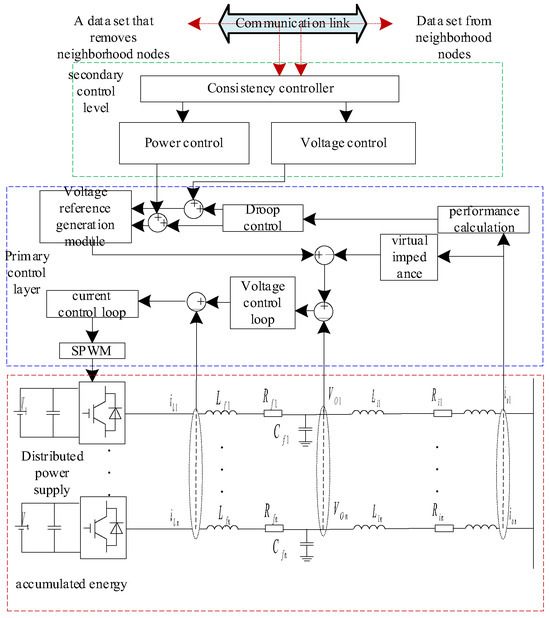
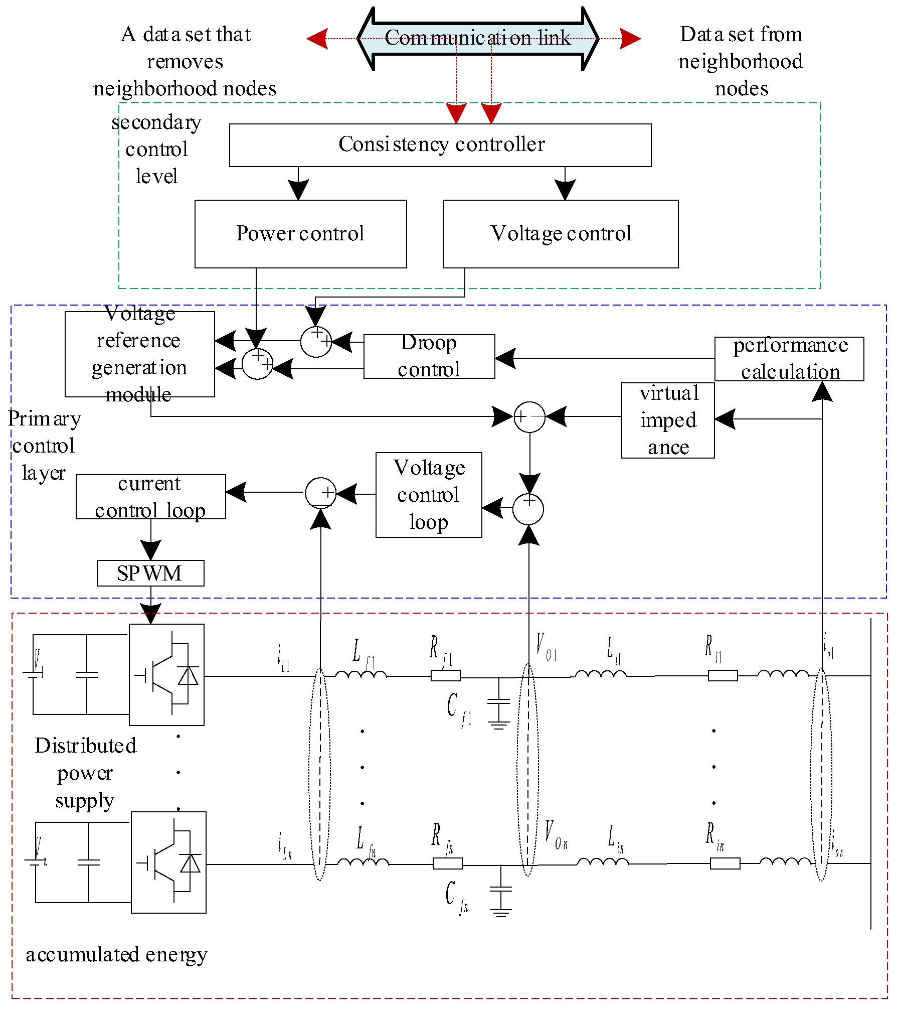
In the multi-energy microgrid cluster system, there are significant differences in line impedance characteristics and spatial distribution of multi-energy-coupling devices. The traditional droop control strategy makes it difficult to realize reasonable distribution of power according to the distributed power supply and energy storage capacity, which leads to the problem of voltage deviation. Therefore, the established event-triggered consensus control framework is shown in Figure 1. The output voltage of the distributed power supply and energy storage equipment in the multi-energy microgrid is controlled and restored to the rated reference value. At the two control levels, each distributed power supply and energy storage device acts as an intelligent node in the network, and each intelligent node supports information interaction between controllers. The event-triggered consistency condition is set based on the operation characteristics of the multi-energy microgrid cluster system, and the event-triggered consistency algorithm is integrated into the controller. Through intelligent control, coordinated control between multi-energy microgrid clusters is realized, so that the voltage of the multi-energy microgrid can be accurately adjusted to the rated value. When the event is triggered, the secondary controller will collect the state information of the multi-energy microgrid and send it to the adjacent multi-energy microgrid. At the same time, it receives state feedback from adjacent microgrids. Based on the deviation control and reactive power compensation mechanism, the system can effectively adjust the voltage deviation.
Figure 1.
Multi-energy microgrid event-triggered consensus control schematic diagram.
Since the supply of gas in the multi-energy microgrid cluster system can be provided outside the microgrid cluster system, the supply of electric energy and heat energy is mainly transmitted within the multi-energy microgrid cluster system to achieve energy self-sufficiency within the multi-energy microgrid cluster system. In order to realize the accurate power sharing of each coupling device in the multi-energy microgrid cluster system, combined with the dynamic event-triggering condition, a control method is designed to meet the consistency target between the power output and the voltage regulation coefficient in the multi-energy microgrid cluster system. The event-triggered consistency condition is set to:
where is the power output of the multi-energy microgrid cluster system. is the voltage regulation coefficient.
Let . According to Formula (4), can be expressed as:
The event-triggered voltage output power consistency control law is designed.
where is the multi-energy microgrid output power rating. is the voltage regulation coefficient of the multi-energy microgrid. is the voltage rating of the multi-energy microgrid. is the actual value of the multi-energy microgrid voltage. is the gain coefficient of the output power event-triggered consensus controller. is the connectivity between multi-energy microgrid cluster systems. There is a communication link between the ith subsystem and the jth subsystem. Unicom is 1, otherwise is 0.
Firstly, for the multi-dimensional event-triggered consensus control framework of the thermal/electrical/gas-coupling pressure system, the standardized modeling and basic assumptions are given as the basis for subsequent proof:
Multi-node coupled system dynamics
Considering the thermal/electrical/gas pressure-coupling system with N nodes, the state vector of the ith node is , which corresponds to the heat network pressure of node i, the voltage/frequency equivalent pressure of the grid node, and the pressure of the gas network node. The overall dynamics of the system are:
where
is the system state matrix and is the control input matrix, which satisfies (A, B) stabilizability.
is the neighbor set of node i, and is the coupling weight, corresponding to the transmission admittance of the heat/electricity/gas network.
Ais the control input of node i.
Multidimensional event-triggering mechanism
The kth trigger time of the ith node is defined as , the state-sampling value of the trigger time is , and the measurement error between the two triggers is:
The multi-dimensional event-triggering conditions are designed as follows:
where is the trigger threshold coefficient, and are the exponential decay term parameters, and is the latest trigger time of neighbor j before time t.
Consistency control law
Distributed consensus control law is adopted:
where K is the feedback gain matrix to be designed, which is selected by the Riccati equation. A positive definite matrix P > 0 exists, which satisfies:
is the minimum non-zero eigenvalue (Fiedler value) of the communication topology Laplacian matrix, is a given positive definite weight matrix, and is assigned.
Taking the lower bound of the minimum interval for all nodes, the interval between any two triggers (whether the same node or not) is not less than . Therefore, in any finite time interval [0, T], the total number of triggering events of the system does not exceed c, which strictly excludes Zeno behavior.
5. Event-Triggered Cooperative Control Method for Multi-Energy Microgrid Cluster Based on Event-Triggered Control
In a multi-energy microgrid cluster system, in order to ensure the realization of the control objectives, each multi-energy microgrid will continuously interconnect information to ensure the stability of the energy supply of the entire cluster system. In the actual process, in order to achieve the control objectives of the multi-energy microgrid, by designing an appropriate trigger mechanism, the amount of information and calculation can be reduced to a lower level without affecting the realization of the control objectives. Therefore, this paper introduces the event-triggered control method to further achieve interconnection control of the proposed multi-energy microgrid cluster. In addition, because the transmission of each energy flow in the multi-energy microgrid system has a different inertia duration, the response speed of each type of energy in the system is different. For example, the adjustment speed of thermal energy is slower than that of electric energy. The event trigger mechanism is triggered according to the trigger conditions and does not work periodically. Therefore, for multi-energy microgrid systems, different energy systems can have different response times, which greatly reduces the amount of calculation. The power consistency protocol of a multi-energy microgrid based on an event-triggered mechanism can be expressed as:
where is the auxiliary control input signal of the multi-energy microgrid. is the power input signal of the multi-energy microgrid auxiliary control. represents the output power of the thermal subsystem of the multi-energy microgrid. is the adjustment parameter of thermal energy control. is the rated output power of the thermal subsystem. is the thermal output power coupling gain of the thermal subsystem in the multi-energy microgrid cluster system. is the electric output power coupling gain of the power subsystem in the multi-energy microgrid cluster system. is the actual power output of the power subsystem in the multi-energy microgrid cluster system. is the rated power of the output power of the power subsystem in the multi-energy microgrid cluster system. is an adjacency matrix element, which represents the coupling between multi-energy microgrids. denotes the subscript of the nearest trigger time to the current time t when the thermal power is controlled. denotes the subscript of the trigger time closest to the current time t when the electric power is controlled. In order to adopt the event-triggered mechanism control method, it is necessary to design an event-triggered detector for each multi-energy microgrid subsystem in the multi-energy microgrid cluster system to determine when the sampling information is used to update the control action. The trigger condition for power control in the multi-energy microgrid subsystem is expressed as:
Here, and are positive scalars, and the thermoelectric power-sharing error between the current time and the latest event trigger time is represented by and , respectively. and represent the sum of thermal power error and electrical power error between the ith multi-energy microgrid subsystem and other multi-energy microgrid subsystems, respectively. and are denoted by:
Similarly, and can be expressed as:
Formulas (27)–(30) determine the distribution of electric, thermal and gas power in the multi-energy microgrid cluster system in the corresponding event-triggered control process. According to the established controller model, the protocol for the event-triggered mechanism of the controller can be expressed as:
where represents the subscript of the nearest trigger time of the multi-energy microgrid system control from the current time t. Similarly, for the event-triggered control protocol, the corresponding trigger conditions need to be designed, which can be expressed as:
and can be expressed as:
where is a positive number, according to the event-triggered control protocol and triggering conditions in the above formula. The energy interaction between multi-energy microgrids can be reduced in the event of voltage recovery in the multi-energy microgrid subsystem.
According to the control objectives of the controller in the multi-energy microgrid cluster system, the minimum control protocol for realizing the energy exchange between the subsystems can be expressed as follows:
where denotes the pressure control, which is a subscript of the nearest trigger time from the current time t. The trigger conditions of the corresponding control protocol are:
and can be expressed as:
where . Let , and the closed-loop system equation of microgrid i in the multi-energy microgrid cluster system can be expressed as:
where, , , and . The number of microgrids in the multi-energy microgrid cluster system is represented by n. The Laplacian matrix of the information topology is represented by L.
In summary, the proposed multi-energy microgrid cluster event-triggered control method can achieve accurate power sharing between multi-energy microgrids. The application of the event-triggered mechanism greatly reduces the amount of data transmitted between the subsystems of the multi-energy microgrid.
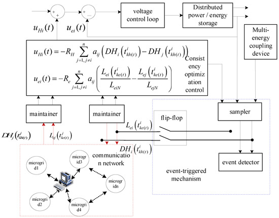
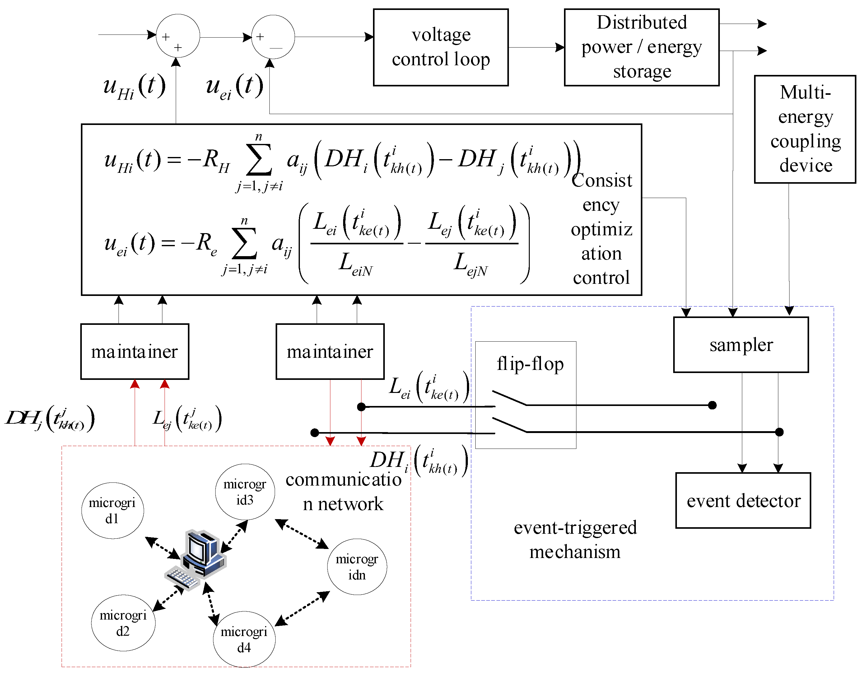
With the goal of testing the consistency control model and trigger conditions established above, a multi-energy microgrid cluster control method based on a data-sampling event-triggered mechanism is designed as shown in Figure 2. In the control block diagram, the sampler is responsible for collecting the information on the state of the power supply and energy storage in the multi-energy microgrid and transmitting it to the event detector. The event detector determines whether the event trigger condition is satisfied. When the power supply and energy storage output in the multi-energy microgrid meet the set controller threshold and the trigger condition, or its adjacent multi-energy microgrid meets the event trigger condition, the controller of the power supply and energy storage in the multi-energy microgrid will update the control signal. The role of adding a zero-order holder in the control process is that the system can maintain the measured value of the previous trigger moment until the next event trigger moment arrives. The event-triggered control strategy only performs trigger detection at the periodic sampling time in the multi-energy microgrid cluster system.
Figure 2.
Multi-energy microgrid cluster event trigger mechanism control block diagram.
6. Dynamic Frequency Control Strategy of the Multi-Energy System
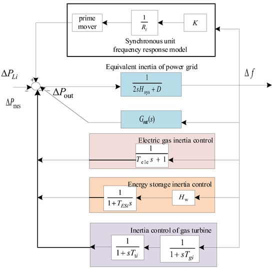
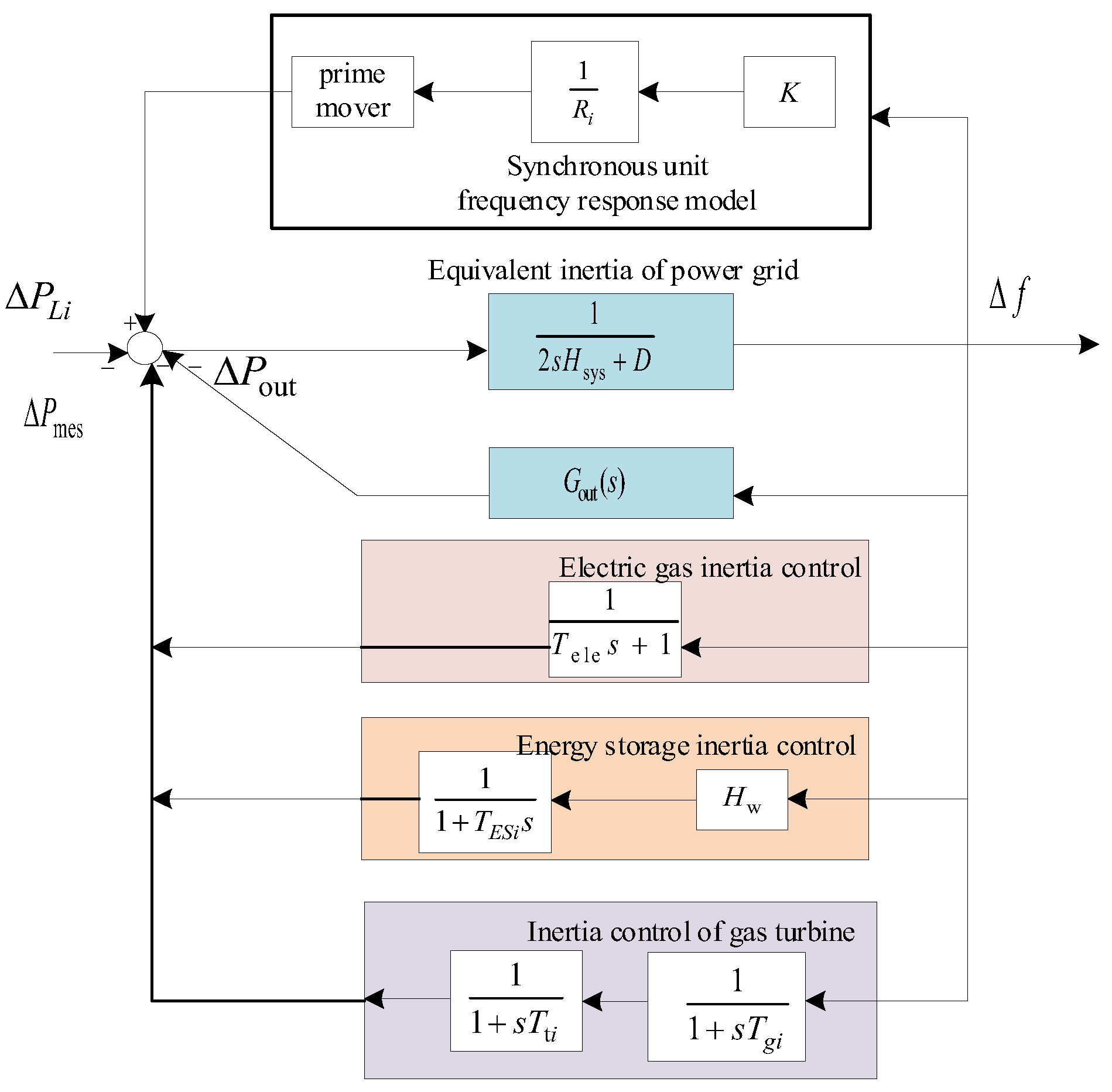
When load frequency control is carried out in the power system, it concerns the overall performance of all generators in the multi-energy microgrid cluster system. Therefore, the dynamic characteristics of the voltage and power angle of the synchronous generator and the oscillation between multiple synchronous generators are ignored in the model. The micro gas turbine-load model is combined with the battery energy storage model, and the fluctuation in power of renewable energy and the conventional load fluctuation are combined as the total power disturbance. Thus, the load frequency control system model of the multi-energy microgrid system is constructed, as shown in Figure 3.
Figure 3.
Adaptive leading compensation control of the multi-energy system.
In the multi-energy microgrid frequency control system model, Gout (s) is the inertia response transfer function outside the multi-energy microgrid. The frequency response of the external power grid is equivalent to a third-order transfer function, which can be referred to in [24]. When the multi-energy microgrid has frequency support requirements, the traditional synchronous unit and multi-source energy storage can be used to support the inertia together. In the process of disturbance, synchronous units and multi-source energy storage can participate in the support power distribution of the multi-energy microgrid. Therefore, the equivalent inertia time constant of the multi-energy microgrid considering multi-source energy storage can be expressed as:
where is the equivalent inertial time constant of the multi-energy microgrid considering multi-source energy storage. is the kinetic energy provided by the synchronous unit in the multi-energy microgrid. provides virtual kinetic energy for multi-source energy storage. is the total installed capacity of the multi-energy microgrid. is the inertial time constant of the multi-energy microgrid multi-source energy storage equipment j. is the rated capacity of the multi-energy microgrid multi-source energy storage equipment j.
7. Frequency–Voltage Cooperative Control of the Multi-Energy System
7.1. Frequency–Voltage Collaborative Optimization Control Model
In order to realize the frequency–voltage dynamic control based on the multi-energy system, it is necessary to obtain the PMU data of the interconnected node phasor measurement unit (Phasor Measurement Unit) between the multi-energy microgrids and the PMU data of each online voltage-monitoring area. The former is used for frequency dynamic control modeling, while the latter is used for voltage dynamic control modeling, and the frequency–voltage cooperative control model of the multi-energy system is established.
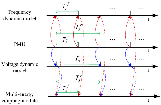
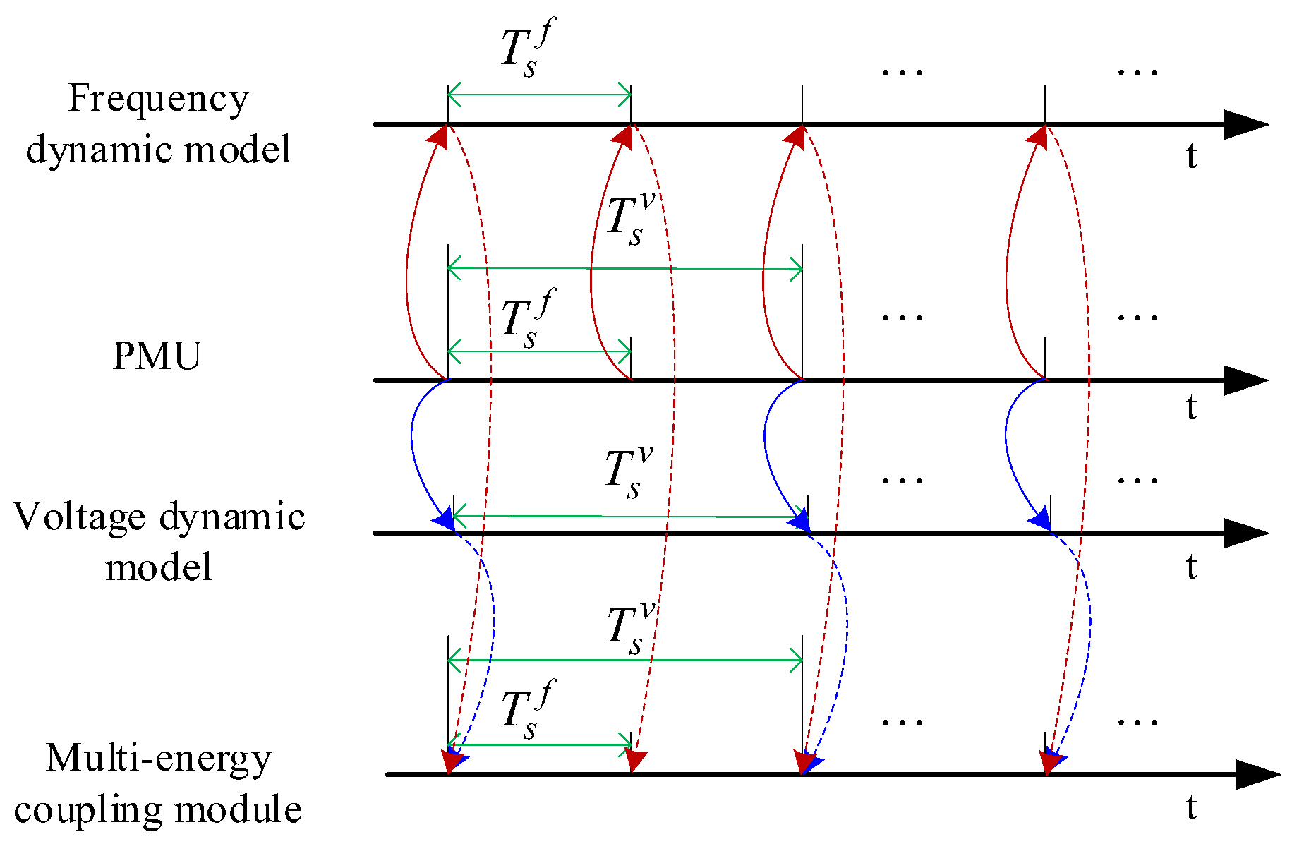
In the multi-energy system, the control information comes from multiple node data points when the system voltage is controlled. In the process of voltage control, the data transmission time is greater than the frequency control time. Therefore, the period of the design frequency sampling time and the voltage sampling time is set to , , respectively, to meet < . The information interaction mechanism between control signals is shown in Figure 4.
Figure 4.
Multi-energy coupling module information interaction mechanism.
The phasor measurement unit of the multi-energy system microgrid interconnection node transmits the frequency sampling value of the microgrid to the frequency dynamic model at each interval , forming the reference value of the active power output control of the multi-energy coupling module. The phasor measurement unit that monitors the voltage collects the voltage of the interconnected nodes of the multi-microgrid, with as the step size. Through the calculation of the system voltage stability control criterion, the active and reactive power output reference values of the multi-energy coupling module are formed.
According to the dynamic model of the frequency and voltage control of the interconnected nodes in the multi-energy system, the discrete time domain state space expression of the frequency and voltage cooperative control model of the power subsystem in the multi-energy system is obtained by using the forward Euler discretization method:
where is the difference between the state variables of the current moment and the previous moment of the information collected at the interconnection node of the power subsystem in the multi-energy system. It is mainly the frequency and voltage deviation at the interconnected nodes. The active and reactive power variation in the renewable energy output of the multi-energy-coupling module and the SOE variation in the multi-energy energy storage system are represented by the incremental matrix as follows:
The control variables in the multi-energy system are mainly the reference values of the active and reactive power output of the energy-coupling module. The control matrix can be expressed as:
The increment in the disturbance variable in the multi-energy system is represented by , which is the equivalent value of active power imbalance at the coupling node of the multi-energy microgrid.
The output stability of the power subsystem in the multi-energy system mainly refers to the frequency and voltage, which is expressed in the form of vector :
In Equation (45), the dynamic characteristics of the multi-energy system are described in matrix form. Matrix A represents the law of the sampling period of the state variable changing with time. Matrix B represents the sensitivity of the multi-energy coupling output change to the system state. The disturbance variable matrix D represents the influence of the active power imbalance of the interconnected nodes of the multi-energy system on the system frequency. Matrix C represents the mapping relationship between the frequency, voltage and state variables of the interconnected nodes. The dynamic control model of the multi-energy system is constructed through the coordination between matrices, which lays a foundation for the subsequent system stability control.
7.2. Frequency–Voltage Control Based on the Adjusting Weight Constraint
Considering the difference in power support demand at different stages of multi-energy system contact point frequency and voltage after disturbance, the active–reactive power regulation ability of the multi-energy coupling module is constrained by the coupling device and the output power of the power supply. A dynamic matching control method for the frequency and voltage situation and the control target weight of interconnected nodes between power subsystems of the multi-energy microgrid is proposed. When the system is subject to external disturbances, the frequency and voltage of the interconnected nodes can be automatically adjusted according to the situational awareness of the system to achieve dynamic collaborative support between multiple energy sources. When the frequency fluctuates violently, the power subsystem may be forced to enter the emergency operation condition, which in turn triggers the low-frequency load-shedding protection action or high-frequency generator-tripping measures in the interconnected multi-energy system. At the same time, if the voltage of the interconnected node drops or rises sharply, the system will automatically switch to the low-voltage ride-through or high-voltage ride-through operation mode. At this time, the multi-energy system will give priority to the reactive power optimization control strategy. The weight variation index is:
where k + i|k represents the predicted value of the variable at time k + i at time k in the multi-energy system. fref and vref are the reference values of the interconnection point frequency and voltage of the microgrid in the multi-energy system. Δfmax is the maximum historical fluctuation value of the microgrid in multi-energy system when the load disturbance, near-end short-circuit fault and renewable energy output disturbance occur in the power subsystem. Δvmax is the maximum historical fluctuation value of the microgrid in the multi-energy system under severe scenarios such as load disturbance and near-end short-circuit fault in the power subsystem. Combined with the stable operating conditions of the power subsystem, set Δfmax = 0.5 Hz.
In the multi-energy system, on the basis of ensuring the frequency and voltage stability of the system, the loss caused by multi-energy coupling, such as in the energy storage equipment and scheduling process, should be considered in the whole control process. Therefore, the adjustment cost model is established to ensure the economy of the adjustment process by establishing the adjustment cost model constraints. The predictive control objective is expressed as:
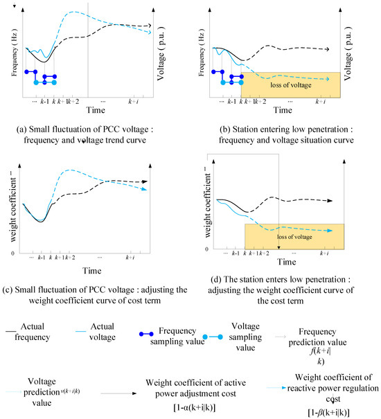
where TP is the predictive time domain of objective function control. TC is the control time domain of the objective function. Cl is the power offset cost coefficient in the control process of renewable energy and energy storage. represents the frequency support effect at the interconnected nodes. represents the voltage support effect at the interconnection node. denotes the cost weight coefficient for active power regulation. represents the cost weight coefficient for reactive power regulation. When the voltage drops at the interconnected nodes in the multi-energy system, whether the renewable energy in the multi-energy system enters the low-voltage ride-through state after the disturbance is determined. As shown in Figure 5, the vector measurement unit collects frequency and voltage data according to the Tsf and Tsv time intervals. Then, the multi-energy coordination controller obtains the frequency component f(k) and the voltage component v(k), which is based on the frequency–voltage cooperative control strategy. The dynamic changes in electrical parameters in TP in a specific time window are calculated. Thus, the frequency prediction value f(k + i|k) at the interconnected nodes in the cluster system and the voltage prediction value v(k + i|k) at the interconnected nodes in the cluster system are obtained.
Figure 5.
State quantity–target weight dynamic matching mechanism diagram.
The active–reactive power regulation of multi-energy coupling and the multi-energy storage module in the multi-energy system is limited by the capacity of the power supply. The active–reactive power output coupling relationship is as follows:
where Sl,N represents the rated capacity of each power source and energy storage device in the multi-energy cluster system.
In order to ensure the accuracy of the support effect of each energy output on the active and reactive power of the system in the multi-energy microgrid, considering that the f-P coupling strength is higher when the frequency and voltage fluctuation directions are different in the power subsystem, the active and reactive power regulation of the system is constrained. The increase or decrease in output command in the control process can be expressed as:
If the values of electrical quantities are in the conventional fluctuation range, as shown in Figure 5a,c, the system will reasonably allocate the control coefficients to the two control dimensions of frequency regulation and voltage stability according to the preset weight allocation strategy. If it is predicted that it may cause a low-voltage ride throughout the system, as shown in Figure 5b,d, β(k + i|k)will change sharply and tend to 1, which is much larger than α(k + i|k). The control algorithm will be dynamically adjusted according to Formula (39), reducing or even eliminating the penalty of reactive power output, and prompting the multi-energy microgrid system to preferentially perform reactive power compensation operations, thereby achieving fast and stable control of the grid-connected point voltage.
8. Experiments and Simulations
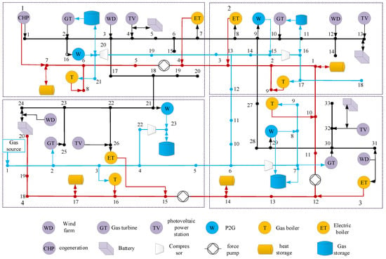
In order to verify the effectiveness of the proposed method and further verify the effectiveness of the event-triggered multi-energy microgrid cluster frequency and voltage optimization control, the simulation system shown in Figure 6 is established for voltage control simulation verification.
Figure 6.
Electric, thermal, cold, hydrogen multi-energy system cluster network.
In order to analyze the cooperative optimization control effect of distributed energy storage, it is assumed that the influence of the operation process of the gas and heat storage equipment in the system on the gas and thermal network can be neglected, and the distributed multi-energy storage system only provides the necessary reactive power support for the power grid. This study takes the simulation system of Figure 6 as an example, and the key operating parameters of the system are shown in Table 1, Table 2 and Table 3.
Table 1.
Gas subsystem parameters.
Table 2.
Thermal subsystem parameters.
Table 3.
Key parameters of the system.
Aiming at the natural transmission time-scale difference of the three heterogeneous energy subsystems of heat, electricity and gas, an independent minimum event interval is set for each type of controller to avoid Zeno behavior and redundant triggering from the physical characteristics. The exclusive minimum event interval time assignment for each subsystem is shown in Table 4.
Table 4.
Exclusive minimum event interval time assignment for each subsystem.
Complete event-triggered execution temporal logic
The sampling stage: Each 1 ms global synchronous clock triggers the bottom sampling of all nodes and collects the original state data of frequency, voltage, heat network pressure and gas network pressure of the whole network at the current time.
Subsystem state screening upload: Upload a frequency-sampling value to the frequency dynamic control model every 20 ms, and upload a voltage-sampling value to the voltage dynamic control model every 10 ms; after the thermal- and gas-side state variables are sampled based on 1 ms, only the minimum event interval nodes of the corresponding subsystem participate in the trigger verification.
Trigger condition determination: The event detector checks the trigger conditions of the four types of controllers synchronously at each 1 ms node. At the same time, it checks the local current state deviation of the subsystem and the state error of the latest transmission of adjacent nodes. Only when the preset trigger condition is satisfied and the interval from the last trigger time of the controller is greater than the corresponding exclusive minimum event interval time is it determined to be an effective trigger event.
Control update and communication: After the trigger is effective, the controller immediately updates the control output based on the latest sampling value and sends the state information of the current node to the adjacent multi-energy microgrid node for the subsequent trigger condition calculation of the adjacent nodes.
Non-trigger cycle maintenance: During the non-effective trigger period, the output of all controllers maintains the control value at the last trigger time, and there is no need to repeat the sampling, calculation and communication operations, which greatly reduces the frequency of energy interaction between subsystems.
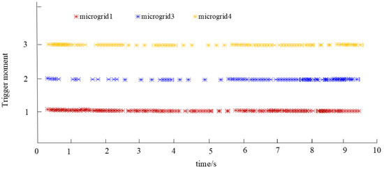
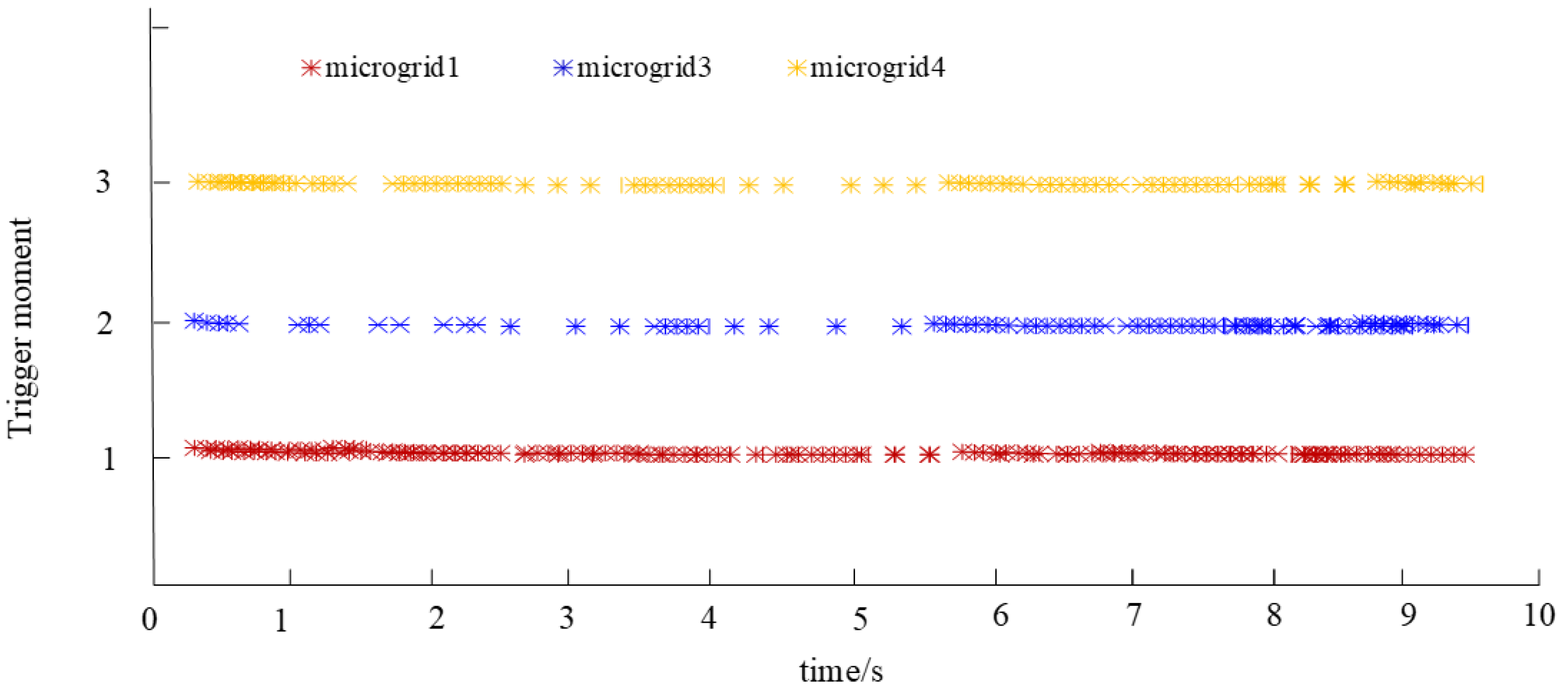
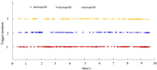
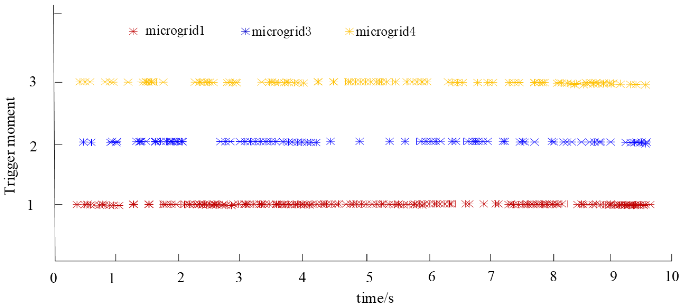
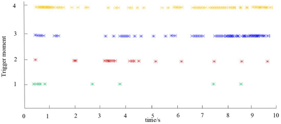
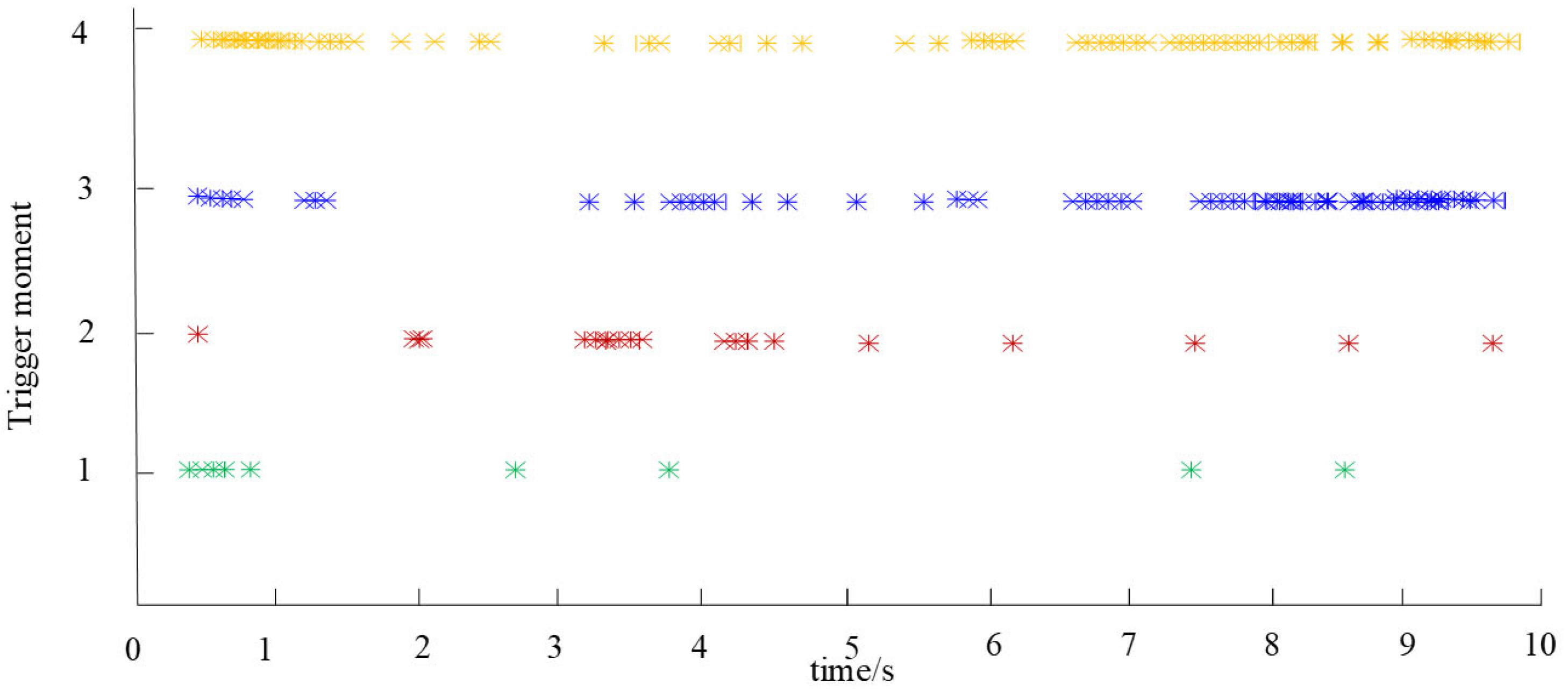
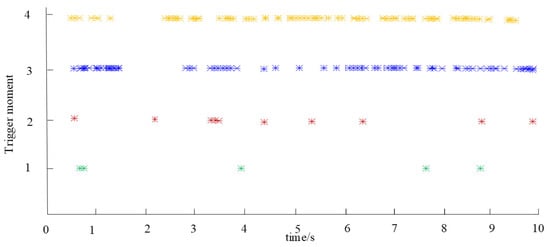
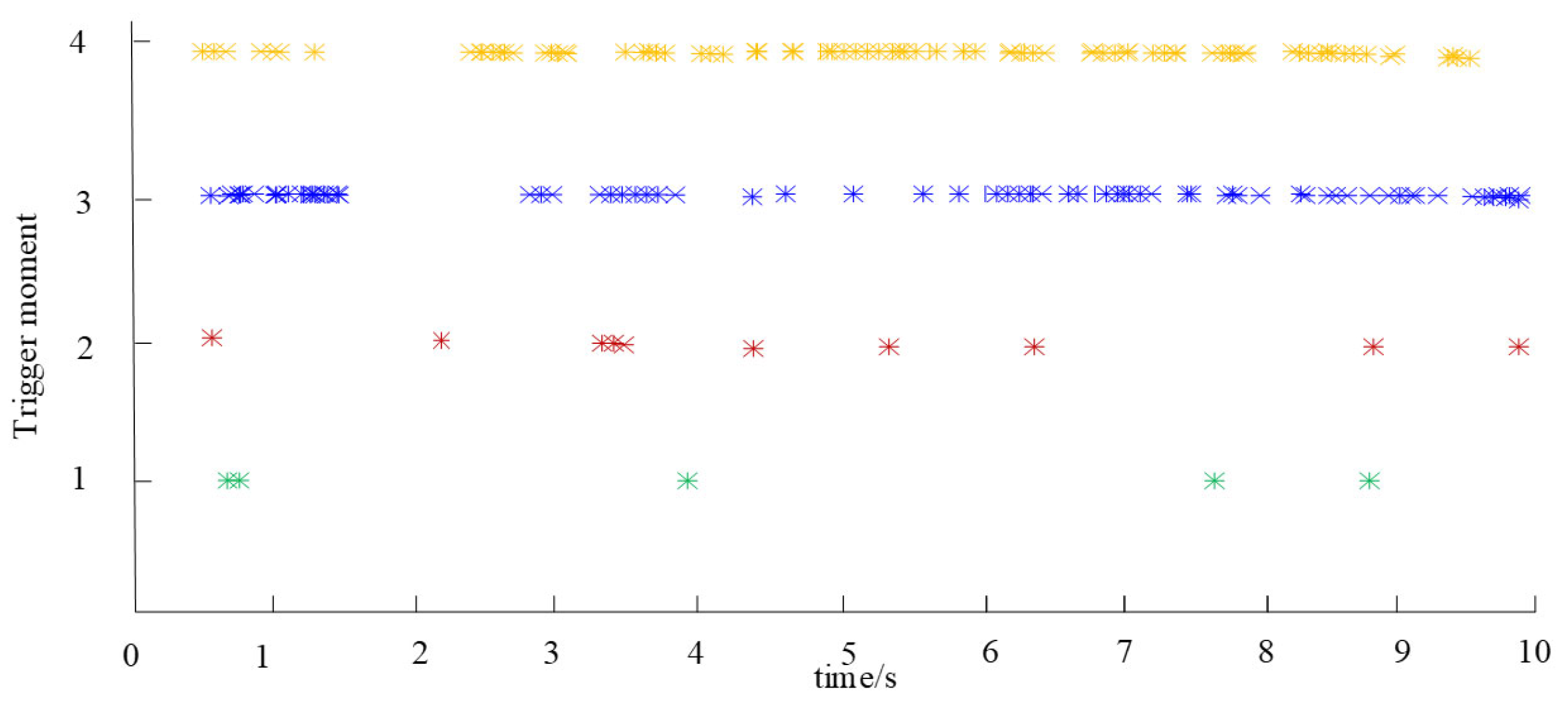
In order to prove that the proposed event-triggered mechanism can reduce the energy interaction between subsystems in the multi-energy microgrid cluster system, Figure 7 and Figure 8 show the trigger time of each device in the multi-energy microgrid cluster system under different control strategies. From the graph analysis, it can be seen that the information transmission trigger time between the subsystems in the multi-energy microgrid cluster is intermittent, and the intermittent time is uneven. Figure 7 shows the traditional information transmission control, and Figure 8 shows the proposed event-triggered control method. The proposed event-triggered distributed control strategy is compared with the traditional information transmission control method, and the two methods are analyzed. The results show that the event-triggered control strategy can greatly reduce the number of control times required for each multi-energy microgrid subsystem to achieve energy balance control. The event-triggered moments of different controllers in multi-energy microgrid subsystem 2 are shown in Figure 9 and Figure 10. Among them, numbers 1–4 represent the gas pressure controller, thermal power output controller, reactive power output controller and active power output controller in the multi-energy microgrid cluster system, respectively, and each point describes the trigger time of each controller.
Figure 7.
Trigger time of each micro-network subsystem.
Figure 8.
Trigger time of each micro-network subsystem.
Figure 9.
Event-triggered moments of different controllers in microgrid subsystem 2.
Figure 10.
Event-triggered moments of different controllers in microgrid subsystem 2.
The simulation results show that the number of triggers of the pressure controller and the thermal power output controller is much smaller than that of the reactive power output controller and the active power controller, and there is no significant difference in the number of triggers between the pressure controller and the thermal output controller, the reactive power output controller and the active power output controller. Obviously, due to the different transmission time scales of each energy subsystem in the multi-energy microgrid cluster system, the controller trigger information transmission in the system has a greater impact. The transmission time scale of electric energy in the multi-energy microgrid cluster system is the smallest. Therefore, if the gas pressure controller, thermal power output controller, reactive power output controller and active power output controller in the system are triggered at the same time, the pressure controller and the thermal output controller will generate a large number of redundant trigger events. Therefore, the proposed event-triggered distributed hybrid control strategy can adapt well to the multi-time-scale characteristics of the multi-energy microgrid cluster system and effectively reduce the overall number of triggers.
Figure 9 and Figure 10 compare the trigger time of the gas pressure controller, thermal power output controller, reactive power output controller and active power output controller in the multi-energy microgrid cluster system under two different trigger mechanisms. Among them, method 1 is the proposed distributed cooperative control strategy based on event triggering, while method 2 is the traditional control strategy based on fixed period information transmission. Method 1 can adjust the trigger time according to the uncertainty fluctuation set in the multi-energy microgrid cluster system, while method 2 follows a fixed time interval for the periodic data-sampling trigger. Whether the multi-energy microgrid cluster system is in the load-adjustment stage or the stable operation state, the event-triggered control strategy can significantly reduce the frequency of information transmission compared with the traditional periodic triggering mechanism. This is because the trigger conditions set by the proposed control strategy and the change in the system state in the two trigger intervals are used to optimize the next trigger time, while the traditional periodic sampling provides a uniform sampling frequency and cannot be dynamically adjusted based on the change in the system state. In the multi-energy microgrid cluster system, due to the frequent fluctuation in load, the power supply in each energy subsystem needs to be continuously adjusted to meet the load demand, so the event-triggered mechanism shows better adaptability. Therefore, the proposed control method is more effective than the traditional periodic sampling method under complex conditions.
The total operation time of this comparative simulation is 300 s, covering the typical operation scenarios of multi-wheel load disturbance and new energy output fluctuation. The multi-energy microgrid cluster system used in the experiment consists of four multi-energy microgrid subsystems. Each subsystem is equipped with four types of independent controllers, which are a gas pressure controller, heat network power output controller, reactive power output controller and active power output controller. There are 16 independent control nodes in the whole system.
The statistical counting rule is as follows: only the time when the controller completes the state update and sends the interactive data to the adjacent microgrid node is counted as an effective communication trigger, and the local verification action that only meets the local trigger threshold but does not transmit data to the adjacent node is not included in the communication counting range.
Statistical results of the global overall communication efficiency
Taking the traditional fixed-cycle full information transmission control strategy as the control group, the overall performance of the proposed event-triggered control strategy is improved as follows:
Under the traditional fixed-cycle strategy, the total number of communication triggers in the 300 s simulation of the whole system is 2160, and the average number of communications per unit time reaches 7.2 per second.
Under the proposed event-triggered control strategy, the total number of triggered communications in the 300 s simulation of the whole system is 561, and the average number of communications per unit time is only 1.87/s.
The global communication traffic is directly reduced by 74.02% compared with the traditional strategy. Compared with the distributed event-triggered frequency–voltage coordination method in the same field that has been published in recent years, the communication overhead can be reduced by more than 48%.
Combined with the multi-time-scale characteristics of the four types of controller adaptation, the communication reduction effects of different types of controllers have different distributions. The corresponding statistical results are as follows:
The gas pressure controller: The total number of triggers in the traditional strategy is 720 in 300 s, the total number of triggers under the event trigger strategy is only 92, and the communication volume is reduced by 87.22%.
Heating network power output controller: The total number of triggers in the traditional strategy within 300 s is 720, the total number of triggers under the event-triggered strategy is only 97, and the communication traffic is reduced by 86.53%.
The reactive power output controller: The total number of triggers in the traditional strategy is 720 in 300 s, the total number of triggers under the event trigger strategy is 183, and the communication volume is reduced by 74.58%.
Active power output controller: The total number of triggers in the traditional strategy within 300 s is 720, the total number of triggers under the event-triggered strategy is only 189, and the communication traffic is reduced by 73.75%.
According to the established multi-energy microgrid cluster system operation model, reactive power regulation characteristic model and reactive power regulation characteristics of distributed energy storage, the event-triggered control method is used to solve the voltage fluctuation problem of the multi-energy microgrid cluster system. Four scenarios are set up to simulate and verify the proposed method.
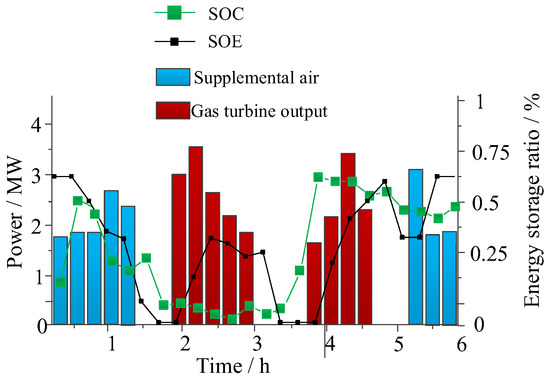
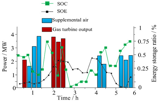
The control results when using distributed multi-source energy storage in the case of S1 are shown in Figure 11. When the output power of the photovoltaic power plant fluctuates and when the heat load demand is small, the photovoltaic power generation is relatively large and the load runs at maximum power. The gas turbine supplements the necessary active power consumption through the combustion of the gas storage tank, thereby providing the necessary reactive power support.
Figure 11.
Charge–discharge state of S1.
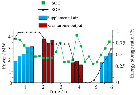
The load change when distributed multi-source energy storage is used in the case of S2 is shown in Figure 12, when the thermal load is low and the photovoltaic output is relatively large. Through the coordinated optimization control of multi-source energy storage, photovoltaic power generation is fully absorbed. In order to ensure the balance of power supply and load power, in the event of a sudden decline photovoltaic power plant and wind power output, the power is released through battery energy storage to achieve balance. The gas in the gas storage tank is converted into electrical energy through the gas turbine to compensate for the lack of electrical energy, which improves the voltage stability of the system to a certain extent.
Figure 12.
Charge–discharge state of S2.
The coordinated optimization configuration of multiple energy storage systems in the case of S4, when the output of the photovoltaic power plant is small and the demand for heat load and electric load increases, is shown in Figure 13. When the output power of the wind farm fluctuates under the dual demand of heating and gas supply, the reactive power loss and heating power of the booster pump are reduced by using the advantages of the large transmission time scale of the heating network, which ensures the stability of the system voltage.
Figure 13.
Charge–discharge state of S4.
Based on the fluctuation in renewable energy output and the change in load in the multi-energy microgrid cluster system, four scenarios are set up for simulation analysis. It can be seen from the simulation results that when the power supply and load fluctuate in the power grid, multi-energy storage control can be realized. Mutual coupling between multiple energy sources and through multi-energy complementarity to ensure the power balance of the power grid can be achieved so as to maintain the stability of the power grid.
When the electric load, heat load and gas load in the multi-energy microgrid cluster system decrease at the same time, the proposed coordinated optimization control strategy based on the adjustable characteristics of pipe network pressure and multi-energy storage can lead to the accurate distribution of electric load, heat load and gas load in the multi-energy microgrid cluster system. In the process of load change, the voltage and pressure of the system also change. The proposed multiple energy storage control method can effectively reduce the voltage deviation caused by the reduction in power load and adjust the voltage to the rated range. Due to the influence of transmission inertia and pipeline resistance in gas and thermal systems, the power of compressors and booster pumps is reduced under the condition of reducing gas supply and heating, and the pipeline pressure cannot reach the rated value instantaneously. The pressure can be stabilized to a safe and stable boundary when the system pressure is reduced by load regulation control.
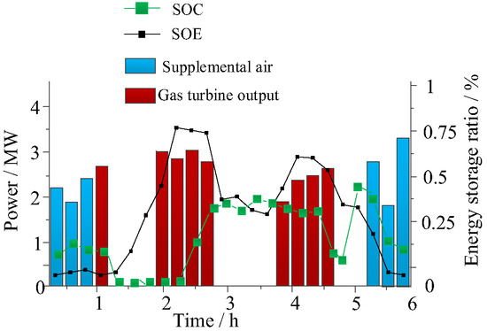
The control results in the case of S3 are shown in Figure 14. In the case of low photovoltaic power generation and wind power generation, gas turbines make up for the lack of wind and solar energy output by converting natural gas into electrical energy.
Figure 14.
Charge–discharge state of S3.
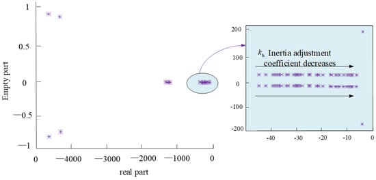
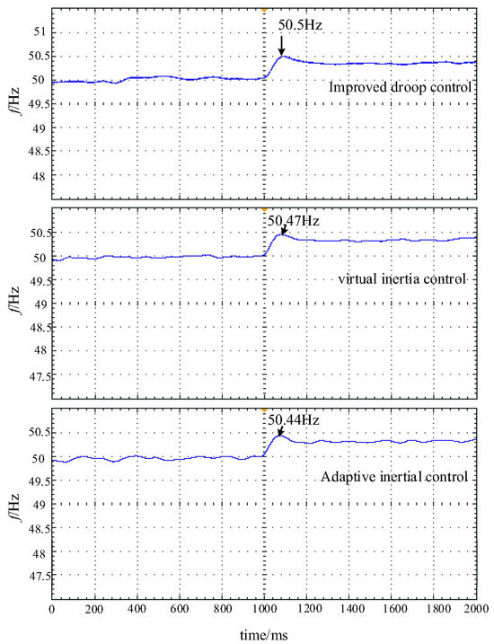
The simulation system is shown in Figure 15. In order to verify the effectiveness of the proposed control method, the simulation system is initially left in the normal operating state, and the load side power is set to drop by 5 MW at 1000 ms. Figure 15 shows the pole root trajectory of the adaptive inertia adjustment coefficient change process. It can be seen from the diagram that when it decreases, the dominant pole of the system moves to the right, indicating that the stability of the system is weakened. However, the eigenvalues of the system are located on the left side of the real axis of the system, indicating that the whole system is stable after adding adaptive inertia control. Different control methods are used to compare the frequency change simulation results, as shown in Figure 16. The specific frequency response of the system is shown in Table 5. It can be seen that the frequency rises to 50.44 Hz and the adjustment time is 160 ms based on the adaptive inertia frequency control strategy. Compared with other control methods, this method has faster frequency recovery and smaller overshoot under load shedding.
Figure 15.
Control system root locus.
Figure 16.
Frequency response of the system to sudden load decrease.
Table 5.
Frequency response of the system to a sudden reduction in load.
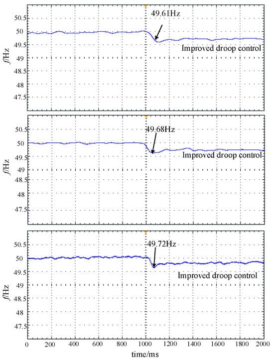
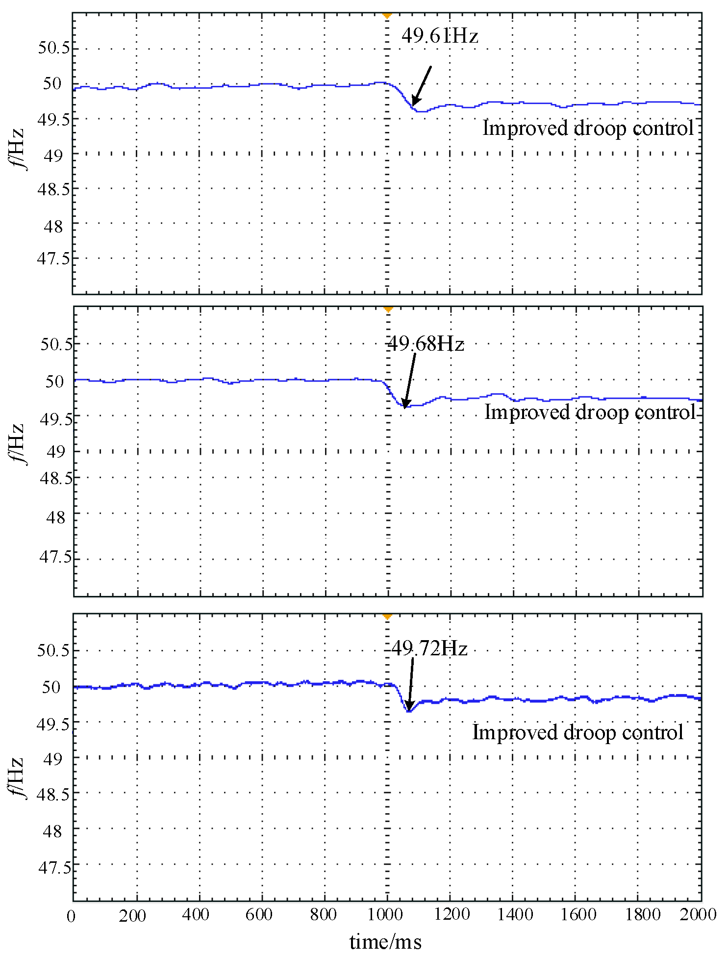
The simulation system is initially in a normal operating state, and the load-side power is set to increase by 5 MW at 1000 ms. Different control methods are used to compare the experimental results of frequency change, as shown in Figure 17. The frequency response of the system under different control modes is shown in Table 6. It can be seen that the frequency is reduced to 49.72 Hz with the adaptive inertia frequency control strategy, and the adjustment time is 100 ms. Compared with other control methods, this method has faster frequency recovery and smaller overshoot under load shedding.
Figure 17.
Frequency response of the system to a sudden load increase.
Table 6.
Frequency response of the system to a load surge.
It can be seen from Figure 16 and Figure 17 that the output frequency of the system will produce an instantaneous offset after an oscillation disturbance occurs. Under the dynamic adjustment to the system inertia, the frequency deviation undergoes a periodic oscillation attenuation process, and finally converges to the initial operating state stably.
By comparing the dynamic response characteristics of the two schemes of virtual inertia control and adaptive inertia control, it can be found that when the adaptive inertia control strategy is adopted, the maximum offset amplitude of the system frequency is significantly reduced, and the output curve shows a smoother transition characteristic. At the same time, the response speed of the system to the disturbance is significantly improved, the oscillation attenuation process is effectively suppressed, and the stability recovery time is greatly shortened. Further analysis shows that this dynamic performance advantage is not only reflected in the comparison with the maximum/minimum value of the fixed virtual inertia parameter scheme, but also in the comparison of other parameter values within the adjustable range of virtual inertia, where the adaptive control strategy still maintains better dynamic response characteristics. This superiority is due to its ability to dynamically adjust the inertia parameters according to the real-time system state, so as to achieve more accurate oscillation suppression and rapid and stable recovery.
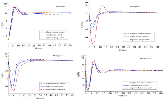
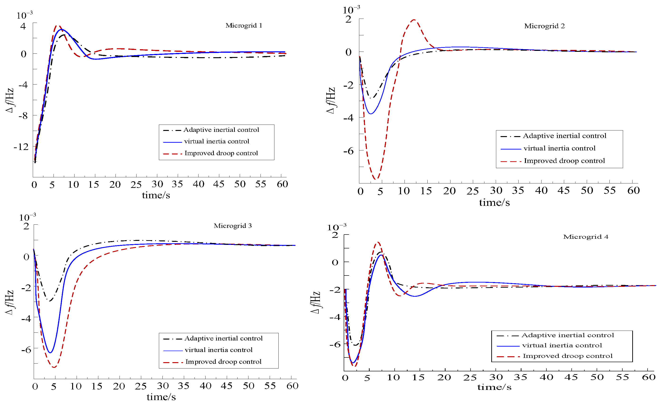
When t = 0 s, a 15% load disturbance is added to microgrid subsystem 1; the frequency response curve of each subsystem is shown in Figure 18. The simulation results of the three algorithms show that the proposed dynamic frequency control method of the multi-energy microgrid has a shorter adjustment time than the control group using other control calculation methods. It can quickly eliminate the system frequency deviation and the tie-line power deviation, and quickly restore stability. Using the proposed optimal control method, when the system has energy fluctuations, it provides certain inertia support for the power subsystem by using the long transmission time inertia characteristics of the thermal pipeline and the gas pipeline.
Figure 18.
The frequency response curves of each subsystem.
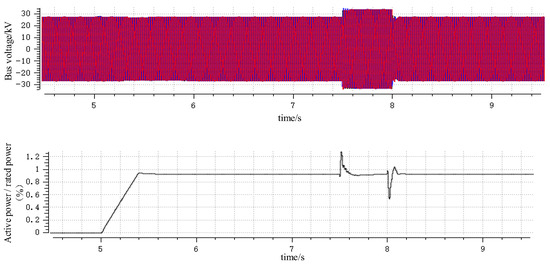
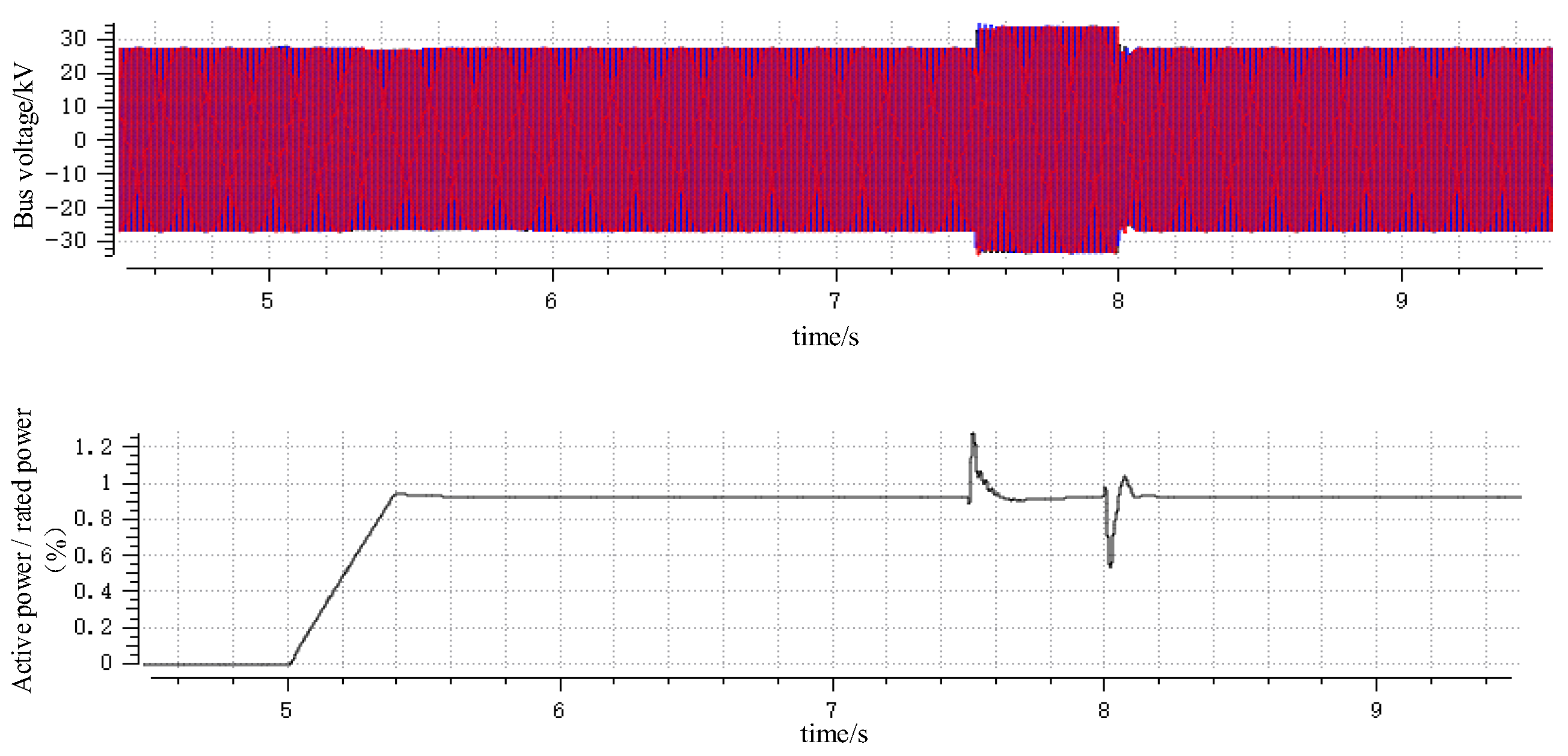
In order to verify the effectiveness of the proposed method, simulation verification is carried out under the condition of sudden fluctuation in output power at different output levels of renewable energy in different energy subsystems. The high-voltage ride-through caused by renewable energy generation in the multi-energy microgrid system is simulated and verified. The simulation results are shown in Figure 19.
Figure 19.
High-power operation and increase in voltage.
The multi-energy microgrid system was compared with state-of-the-art distributed/event-triggered frequency–voltage coordination methods from recent years. A set of control simulations of the mainstream frontier methods in the current field in the past three years were added, two representative methods in the same direction were selected as the comparison objects, and the quantitative indicators were supplemented to form a complete performance comparison, as shown in Table 7.
Table 7.
Comparison results of different methods.
Through this group of comparisons, it can be intuitively proven that the method proposed in this paper is superior to the frontier event-triggered frequency–voltage coordination method that has been published in recent years in the three core dimensions of maximum deviation of frequency response, adjustment speed and communication overhead, and further consolidates the advanced nature of the core method of the paper.
The horizontal performance comparison of the two new types of strategies in Table 8 directly proves the unique advantages of the dynamic weighting mechanism:
Table 8.
Comparison results of different methods.
Through comparison, it can be seen that the dynamic weight mechanism can automatically switch the control priority of frequency and voltage according to the real-time disturbance scene, and automatically allocate the proportion of active and reactive power resources under different working conditions. Compared with the fixed-weight strategy, dual improvement in frequency and voltage control performance is realized at the same time, and the regulation loss of the multi-energy system is reduced.
In the simulation, 30% of the impact nonlinear load is input at , and the distributed photovoltaic output in the cluster drops by 40% at The two most common voltage disturbance conditions in the operation of the microgrid are simulated. All indicators start timing statistics from the moment of disturbance. A quantitative comparison of the full-dimensional voltage performance indicators is shown in Table 9.
Table 9.
Quantitative comparison of full-dimensional voltage performance indicators.
It can be seen from the statistical results that the dynamic weight mechanism can adaptively adjust the distribution weights of the two types of control targets according to the real-time frequency deviation and voltage deviation. In the process of coordinated frequency–voltage control, the voltage mutation is preferentially suppressed, and the voltage overshoot at the moment of disturbance is greatly reduced. At the same time, the duration of the voltage limit is shortened, and the low-voltage/high-voltage protection action of the microgrid is avoided.
The lower steady-state voltage RMS error and reactive power demand mean that the proposed method can reduce the output pressure of reactive power compensation equipment such as distributed energy storage and SVG in long-term operation, reduce the long-term operation loss of the microgrid cluster, and achieve a significant improvement in voltage control performance while taking into account communication efficiency.
9. Conclusions
Whether the multi-energy microgrid cluster system is in the load-adjustment stage or stable operation state, compared with the traditional periodic triggering mechanism, the event-triggered control strategy can significantly reduce the frequency of information transmission. This is because the trigger condition set by the proposed control strategy and the change in the system state in the two trigger intervals optimize the next trigger event. However, the traditional periodic sampling provides a uniform sampling frequency, which cannot be dynamically adjusted based on a change in system state. In the multi-energy microgrid cluster system, due to the frequent fluctuation in the load, the power supply in each energy subsystem needs to be continuously adjusted to meet the load demand. The event-triggered mechanism thus exhibits better adaptability. Therefore, the proposed control method is more effective than the traditional periodic sampling method under complex conditions.
This paper studies the cooperative dynamic frequency optimization control method of a multi-energy microgrid cluster. The problems of inertia reduction and frequency stability control in a multi-energy microgrid is increased. A generalized inertia model in a multi-energy microgrid is established. Combined with the difference in the energy transmission time scale of different energy subsystems, the energy function of a multi-energy microgrid is established to analyze the system frequency stability process, and the inertia energy source in the multi-energy microgrid is obtained, which provides sufficient energy support for the power system and maintains the system frequency stability.
Author Contributions
Data curation, Writing—original draft, Writing—review & editing, P.S.; Conceptualization, Methodology, Writing—review & editing, H.Z. All authors have read and agreed to the published version of the manuscript.
Funding
This research was funded by the National Key R & D Program (2022YFB2403000), Smart Grid Major Project (2030) (2025ZD0805500), and Natural Science Foundation of Jilin Province (YDZJ202601ZYTS201).
Data Availability Statement
The datasets presented in this article are not readily available because the data are part of an ongoing study. Requests to access the datasets should be directed to the corresponding author.
Conflicts of Interest
Author Hao Zuo was employed by Shandong University of Aeronautics. The remaining author declares that the research was conducted in the absence of any commercial or financial relationships that could be construed as a potential conflict of interest.
References
- Hao, Z.; Yun, T.; Zhe, C. Reactive power optimization control for multi-energy system considering source-load uncertainty. Electr. Power Syst. Res. 2024, 228, 110044. [Google Scholar] [CrossRef] [Scilit]
- Oh, G.U.; Hong, C.W.; Ko, J.S. Sensorless Speed Control in Induction Motor Using Deadbeat Discrete Flux Observer Under V/f Control. Energies 2025, 18, 4934. [Google Scholar] [CrossRef] [Scilit]
- Zhang, L.; Li, Y.; Ahn, C.K.; Liang, H. Adaptive Temporal Partitioning for Communication-Efficient Consensus in Nonlinear Multiagent Systems. IEEE Trans. Ind. Inform. 2026, 1–12. [Google Scholar] [CrossRef] [Scilit]
- Robbins, E.; Kuether, R.J.; Pacini, B.R.; Moreu, F. Detecting isolated resonance curves using fixed frequency voltage control tests. Nonlinear Dyn. 2025, 113, 22257–22280. [Google Scholar] [CrossRef] [Scilit]
- Jung, G.G.; Lee, J.S.; Kim, H.S.; Jung, J.H. Design methodology of a voltage controller for a dual-active-bridge converter utilizing spread-spectrum modulation. J. Power Electron. 2025, 25, 393–404. [Google Scholar] [CrossRef] [Scilit]
- Ashrafi, S.; Rozveh, S.A.M.; Khorsandi, A.; Hosseinian, S.H. Control strategy of frequency and DC voltage for interfacing converter of hybrid AC/DC microgrid based on improved virtual synchronous generator. IET Renew. Power Gener. 2025, 19, e13190. [Google Scholar] [CrossRef] [Scilit]
- Shahnazian, F.; Das, K.; Yan, R.; Sørensen, P. Aspects of Relevance of Hybrid Power Plants in Control and Stability of Weak Grids. Energies 2024, 17, 6353. [Google Scholar] [CrossRef] [Scilit]
- Shekher, V.; Sisodiya, A.; Sinha, A.K.; Harsh, H.; Soren, N. Optimal tuning of PID controller for V/f control of linear induction motor using artificial biological intelligence. Frankl. Open 2024, 9, 100183. [Google Scholar] [CrossRef] [Scilit]
- Hou, R.; An, J.; Qin, L.; Zhao, Z.; Cao, Y.; Zhao, X. Small-Signal Stability Analysis and Voltage Control Parameter Design for DC Microgrids. Processes 2024, 12, 2247. [Google Scholar] [CrossRef] [Scilit]
- Su, J.; Zhang, H.; Liu, H.; Liu, D. Lyapunov-based distributed secondary frequency and voltage control for distributed energy resources in islanded microgrids with expected dynamic performance improvement. Appl. Energy 2025, 377, 124539. [Google Scholar] [CrossRef] [Scilit]
- Caballero, D.; Toledo, S.; Maqueda, E.; Ayala, M.; Gregor, R.; Rivera, M.; Wheeler, P. Predictive Voltage Control in Multi-Modular Matrix Converters under Load Variation and Fault Scenario. Technologies 2024, 12, 170. [Google Scholar] [CrossRef] [Scilit]
- Donon, B.; Cubelier, F.; Karangelos, E.; Wehenkel, L.; Crochepierre, L.; Pache, C.; Saludjian, L.; Panciatici, P. Topology-aware reinforcement learning for tertiary voltage control. Electr. Power Syst. Res. 2024, 234, 110658. [Google Scholar] [CrossRef] [Scilit]
- Kumar, S.; Gupta, A.; Bindal, R.K. Load-frequency and voltage control for power quality enhancement in a SPV/Wind utility-tied system using GA & PSO optimization. Results Control Optim. 2024, 16, 100442. [Google Scholar] [CrossRef] [Scilit]
- Pan, R.; Wu, Y.; Yang, Y.; Yang, J. Hybrid synchronization based frequency support control for renewable energy sources integrated MMC-HVDC with capacitor voltage control. Electr. Power Syst. Res. 2024, 233, 110472. [Google Scholar] [CrossRef] [Scilit]
- Misra, S.; Jha, B.; Mishra, V.M. A novel islanding detection method for microgrid using complex voltage unbalance factor. Electr. Eng. 2026, 108, 276. [Google Scholar] [CrossRef] [Scilit]
- Seraji, M.A.; Kazemi, M.H.; Doroudi, A. A distributed consensus-based coordinated approach to global power sharing under sparse-communication with accurate voltage/frequency recovery in hybrid microgrids. Electr. Eng. 2026, 108, 275. [Google Scholar] [CrossRef] [Scilit]
- Wang, L.; Chen, W.; Luo, Y.; Zhang, B.; Jing, L. Improvement method of frequency distribution characteristics of power grid based on integrated inertial control. Electr. Eng. 2026, 108, 261. [Google Scholar] [CrossRef] [Scilit]
- Yan, Y.; Liang, H.; Li, T.; Huang, T. Tunable Funnel-Based Distributed Safety-Critical Formation Maneuvering of Air-Ground Swarms. IEEE Trans. Autom. Control 2026, 1–16. [Google Scholar] [CrossRef] [Scilit]
- Ma, S.; Yang, Z.; Luo, J.; Liu, Z.; Wu, Z.; Wang, L.; Li, B.; Chen, C.; Yun, K. CO hydrate decomposition and spatial temperature characteristics under sudden ambient temperature rise. Energy Fuels 2026, 40, 19488–19495. [Google Scholar] [CrossRef] [Scilit]
- Kumar, K.A.; Salman, H.; Mohammad, S.; Suk, R.J.; Rizwan, K.M. Load shedding for frequency and voltage control in the multimachine system using a heuristic knowledge discovery method. Front. Energy Res. 2022, 10, 1002064. [Google Scholar] [CrossRef] [Scilit]
- Kumar, R.S.; Raj, I.G.C.; Gunapriya, D.; Indragandhi, V.; Subramaniyaswamy, V.; Alaric, J.S. Diagnosis of Broken Bars in V/F Control Induction Motor Drive Using Wavelets and EEV Estimation for Electric Vehicle Applications. Int. Trans. Electr. Energy Syst. 2022, 2022, 9474640. [Google Scholar] [CrossRef] [Scilit]
- Hao, Z.; Yun, T.; Songqing, C. Distributed multi-energy storage cooperative optimization control method for power grid voltage stability enhancement. Electr. Power Syst. Res. 2023, 216, 109012. [Google Scholar] [CrossRef] [Scilit]
- Choi, S.C.; Kim, J.H.; Yoon, Y.D.; Hong, C.; Park, C.H.; Cho, J.H. V/f control technique for mitigating pulsating torque based on active and reactive power sharing in single-phase induction motors. J. Power Electron. 2025, 25, 2251–2261. [Google Scholar] [CrossRef] [Scilit]
- Zhao, S.; Li, K.; Yin, M.; Yu, J.; Yang, Z.; Li, Y. Transportable energy storage assisted post-disaster restoration of distribution networks with renewable generations. Energy 2024, 295, 131105. [Google Scholar] [CrossRef] [Scilit]
- Qin, C.; Zhang, J.; Pang, S.; Ma, L. Event-triggered secondary control for distributed microgrids with time-varying delays. Int. J. Electr. Power Energy Syst. 2025, 162, 110255. [Google Scholar] [CrossRef] [Scilit]
- Ghanimi, H.M.J.; Ghoreishy, H.; Mirimani, S.M. Distributed event-triggered consensus control for microgrid clusters with mixed time-state dependent triggering mechanism. E-Prime—Adv. Electr. Eng. Electron. Energy 2024, 10, 100773. [Google Scholar]

Disclaimer/Publisher’s Note: The statements, opinions and data contained in all publications are solely those of the individual author(s) and contributor(s) and not of MDPI and/or the editor(s). MDPI and/or the editor(s) disclaim responsibility for any injury to people or property resulting from any ideas, methods, instructions or products referred to in the content. |
© 2026 by the authors. Licensee MDPI, Basel, Switzerland. This article is an open access article distributed under the terms and conditions of the Creative Commons Attribution (CC BY) license.