


Abstract
This study proposes a fault-tolerant low-authority injection (LAI) current-sharing strategy for parallel DC-DC converters. A dual-operational-amplifier architecture is adopted, and a resistor–diode injection interface is introduced to limit the influence of the current-sharing loop on the primary voltage-regulation loop. A piecewise injection model and a simplified small-signal model are developed. A three-module 36 V/5 V half-bridge prototype is experimentally evaluated. At total output currents of 30 A and 90 A, the maximum current-sharing errors are approximately 6.0% and 6.4%, respectively. The converter also maintains stable operation during an intentional current-sharing-bus short-circuit test. The proposed LAI method provides a simple hardware-oriented solution that achieves effective current redistribution while restricting sharing-loop authority and improving fault tolerance.
1. Introduction
Parallel operation is an effective approach for increasing the power capability, modularity, redundancy, and thermal utilization of power electronic converter systems. However, unavoidable mismatches among semiconductor devices, passive components, interconnection impedances, sensing circuits, and local voltage references can lead to unequal current distribution among parallel branches [1,2,3]. Current imbalance has been extensively investigated at both the semiconductor-device and converter levels, where parasitic parameters and device tolerances can significantly influence current distribution [4,5]. At the converter-system level, unequal branch currents and circulating currents may increase electrical and thermal stress, reduce available power capability, and adversely affect the reliability of parallel operation [6,7,8,9]. Therefore, accurate and reliable current sharing remains an important design objective for modular power conversion systems [10,11,12].
A variety of current-sharing strategies have been developed to mitigate these problems. Droop-based control regulates the module operating point by introducing an equivalent output resistance or virtual impedance and is attractive because of its decentralized implementation and reduced dependence on a dedicated communication link [13,14,15]. However, improving current-sharing accuracy through a larger droop characteristic generally increases the output voltage deviation, resulting in an inherent compromise between current sharing and voltage regulation. Master–slave current-sharing control provides another widely used approach, in which a designated master module or supervisory controller establishes the current reference for the remaining modules [16,17,18]. Although accurate current tracking can be achieved, system operation becomes dependent on the master controller and the associated reference or communication path.
Average Current Sharing (ACS) provides an alternative solution for parallel converter systems. In an analog ACS architecture, the sensed-current information of the participating modules is combined through a common sharing signal, and each module adjusts its local operating point according to the difference between its own current and the shared current information [19,20,21]. Digital current-sharing, virtual-impedance-based control, instantaneous current-sharing, and communication-assisted coordination have also been investigated to improve dynamic current distribution and system flexibility [22,23,24,25]. These techniques can provide effective current balancing, but their implementation may involve additional sensing, communication, processing, synchronization, or compensation requirements.
More recently, fuzzy and optimization-based controllers, optimized PID regulation, dynamic compensation of resonant converters, current-sharing optimization for nonidentical modules, topology-assisted self-balancing, and intelligent decentralized control have been investigated to improve current distribution under converter mismatch and varying operating conditions [26,27,28,29,30,31]. These studies demonstrate that current-sharing performance depends not only on the selected control algorithm but also on component tolerances, converter dynamics, interconnection characteristics, and the manner in which the current-sharing correction signal interacts with the primary converter controller. From a broader system perspective, converter-level operating characteristics also influence higher-level coordination in converter-dominated power systems. In hybrid AC/DC networked microgrids, converter-model fidelity can affect conversion-loss representation, dispatch feasibility, and computational efficiency [32].
To address this issue, this study proposes a fault-tolerant low-authority injection (LAI) current-sharing strategy for parallel DC-DC converters. Instead of allowing the current-sharing controller to directly dominate the voltage reference or PWM command, the proposed architecture introduces a resistor–diode injection interface between the current-sharing error amplifier and the primary voltage-regulation loop. The high-impedance path intentionally limits the coupling between the two control loops, while the diode branch provides direction-dependent correction. Consequently, the objective of the proposed method is not to claim universally superior current-sharing accuracy or transient performance compared with all existing approaches but to achieve a practical compromise between current redistribution capability and restricted sharing-loop authority.
The main contributions of this work are as follows. First, a dual-operational-amplifier current-sharing architecture is developed to decouple current sensing, error compensation, and voltage-reference injection. Second, a piecewise model of the LAI interface is established considering the diode state, injection network, and operational-amplifier limits. Third, the parallel system is analyzed in terms of common and differential modes to clarify the action of the current-sharing loop. Finally, the proposed method is experimentally verified on a three-module 36 V/5 V prototype under steady-state, load-transient, fault, and thermal conditions.
2. Proposed Fault-Tolerant LAI Current-Sharing Architecture
2.1. Overall Architecture of the Proposed LAI Current-Sharing System
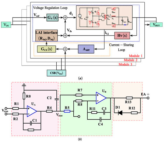
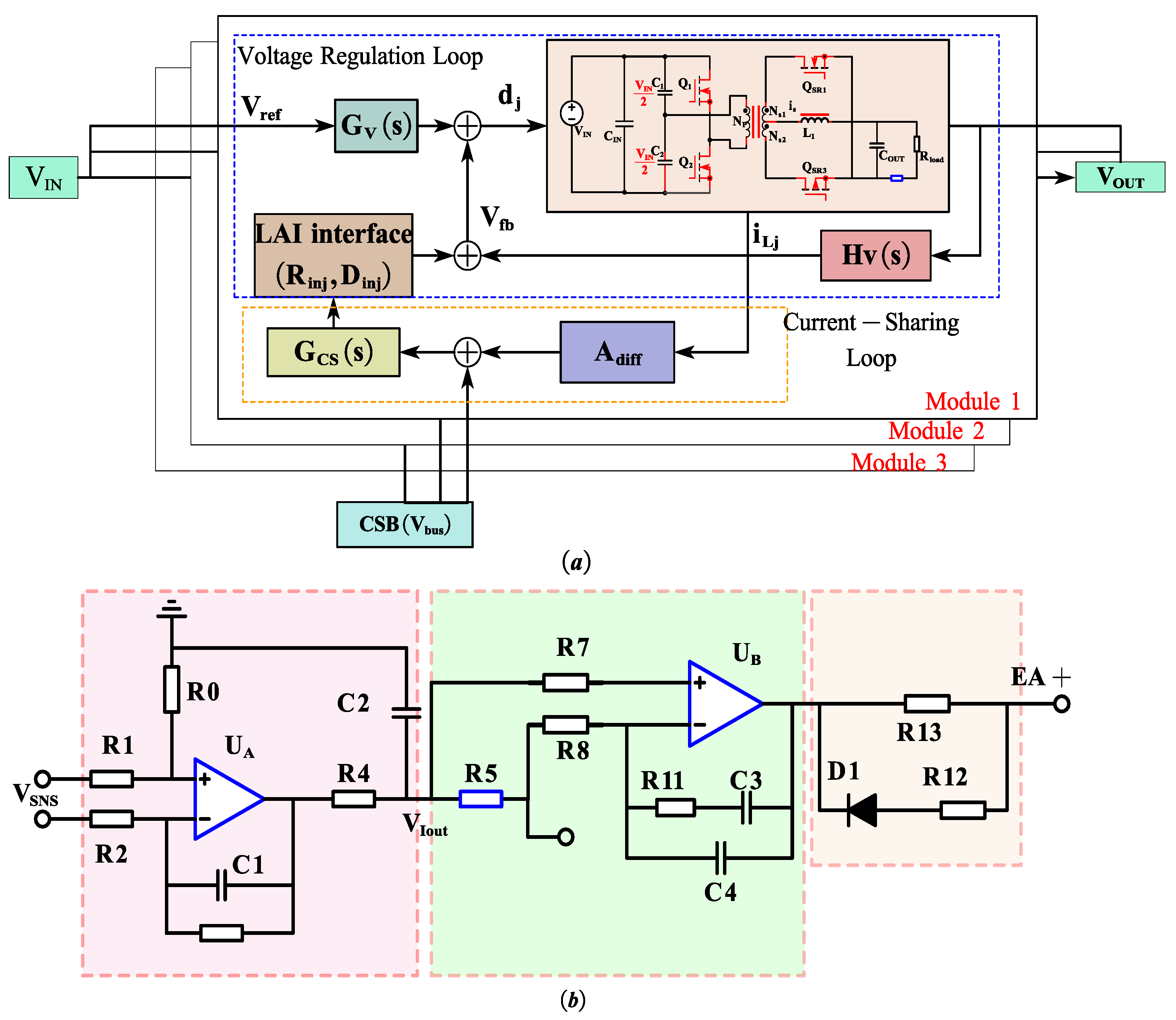
Current-sharing control for parallel DC-DC converters has been extensively investigated using droop-based, active current-sharing, and compensation-based approaches [25,26]. Recent studies have demonstrated that appropriate current-sensing and compensation are essential for suppressing current imbalance caused by converter-parameter mismatch and interconnection impedance [19,28]. Based on these considerations, a fault-tolerant LAI current-sharing architecture is proposed in this work. The proposed topology integrates a power stage with a dual-loop control scheme: an outer voltage loop for output regulation and an inner current-sharing loop for discrepancy mitigation. The control process is illustrated in Figure 1a. The overall structure is composed of three functional blocks illustrated in Figure 1b: a high-precision differential current-sensing stage, an analog current-sharing bus with error amplification, and a LAI interface connected to the primary voltage regulation loop.
Figure 1.
(a) Functional block diagram of the proposed LAI current-sharing control strategy. (b) The overall architecture of the proposed LAI current-sharing system scheme.
The proposed architecture adopts a dual-operational-amplifier configuration. The first operational amplifier (UA) is responsible for extracting the local inductor current information with high common-mode noise immunity, while the second operational amplifier (UB) processes the current-sharing error between the local module current and the average current signal generated by the sharing bus. Different from conventional ACS approaches, the output of the current-sharing error amplifier is not directly connected to the PWM control loop. Instead, the correction signal is injected into the voltage reference node through a high-impedance resistor–diode network, thereby limiting the maximum control authority of the sharing loop.
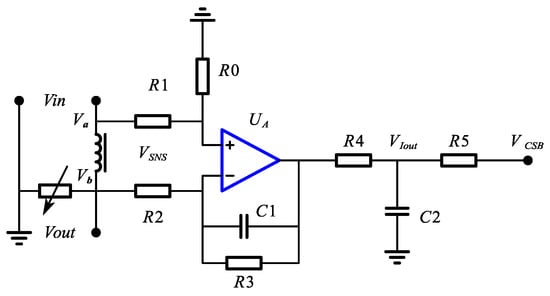
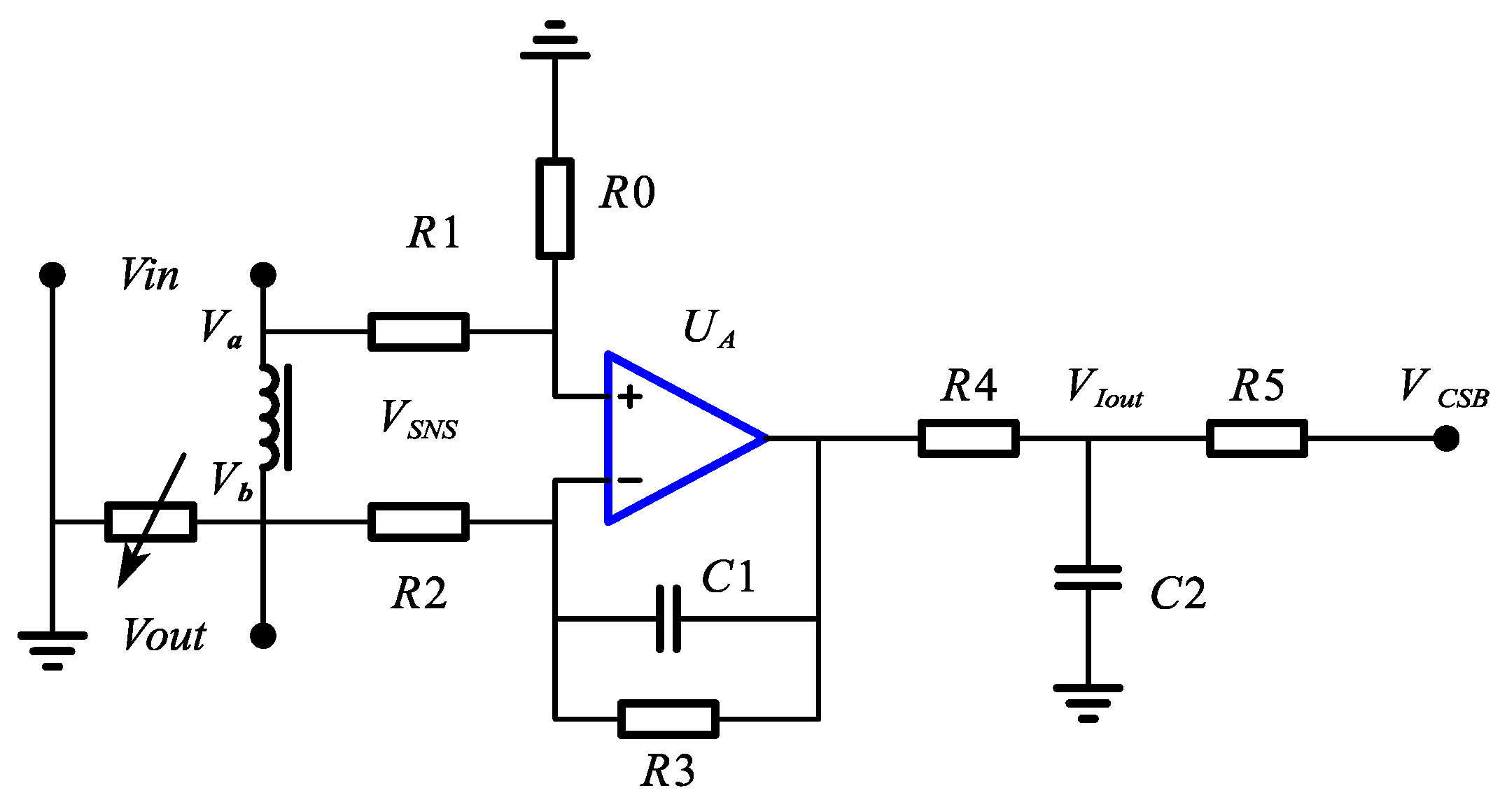
The first-stage high-precision differential sampling circuit is shown in Figure 2. The local inductor current is sensed via a shunt or the DC resistance (DCR) of the inductor, yielding a sense voltage . The output of the sensing stage, , is derived as follows:
Figure 2.
High-precision differential sampling circuit.
The differential sensing gain is determined by the matched resistor ratios (). To suppress high-frequency switching noise, a first-order low-pass filter is integrated with a pole frequency:
Unlike single-ended amplifiers, this differential structure ensures that the current signal remains referenced to the local signal ground while rejecting common-mode transients caused by high switching nodes, which is critical for maintaining a stable sharing bus in high-power-density layouts.
The current-sharing bus () facilitates the exchange of current information between N parallel modules. Each module connects to this common bus through a synchronization resistor . The bus voltage naturally converges to the mathematical average of all module outputs:
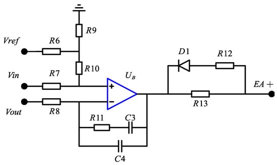
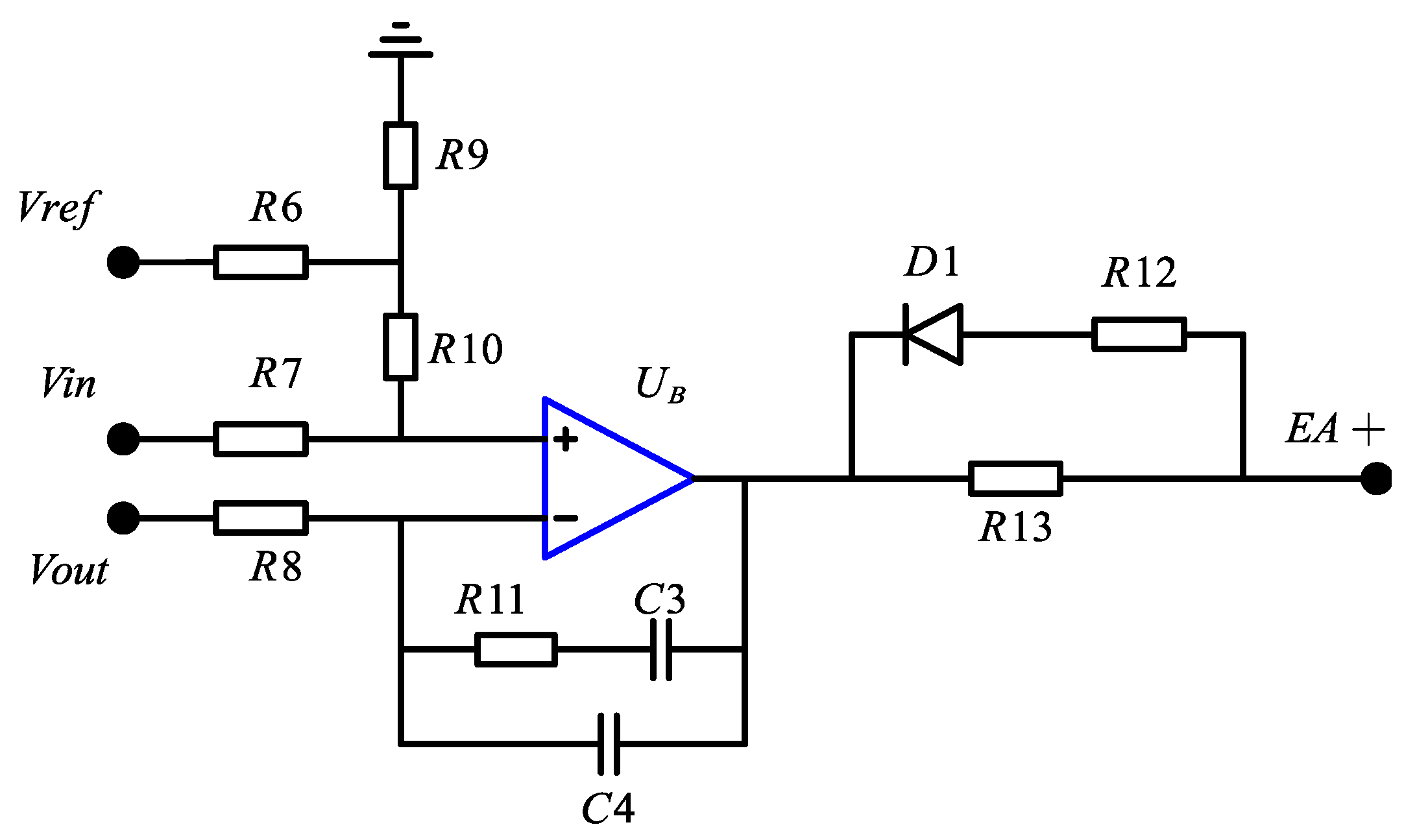
The second-stage analog current-sharing error amplifier (CSEA) circuit is shown in Figure 3.
Figure 3.
Current-sharing error amplification circuit.
It compares the local current signal with the global average . The error signal is processed by a proportional-integral (PI) compensator defined by and . The transfer function of the CSEA is:
The PI characteristics ensure zero steady-state error in current distribution. If a module’s current is higher than the average, decreases, initiating the injection mechanism to reduce that module’s output contribution.
2.2. Low-Authority Injection Interface
In conventional active current-sharing and master–slave implementations, the current-sharing correction is generally introduced by modifying the local voltage reference, current command, duty–ratio command, or equivalent output characteristic [16,17,18,19,20,21]. Such approaches provide effective current regulation, but the magnitude of the correction command also determines the degree of interaction between the current-sharing controller and the primary converter-control loop [18,20]. Against this background, the key feature of the proposed method is the introduction of a low-authority injection interface between the current-sharing error amplifier and the primary voltage-control loop. In conventional ACS structures, the sharing correction signal is directly injected into the voltage reference or PWM modulation stage. Such high-authority control can improve current balancing accuracy but may cause excessive voltage deviation when the sharing signal becomes abnormal.
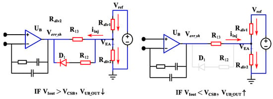
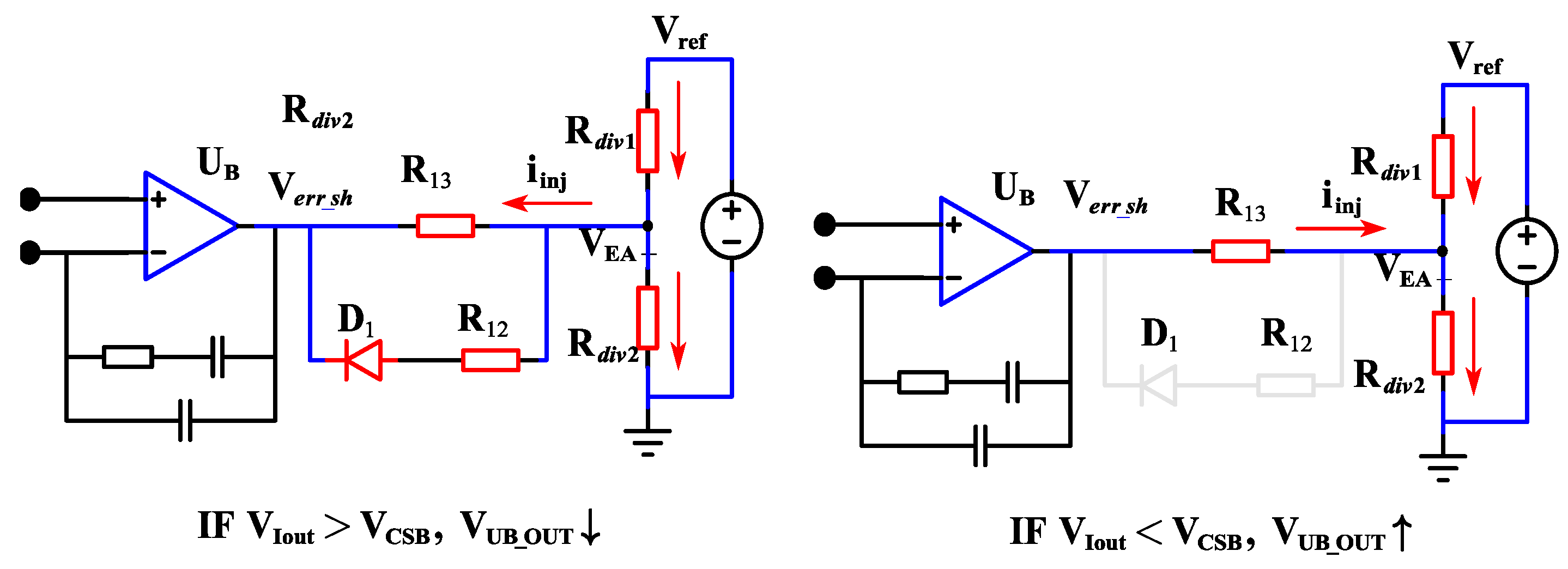
In the proposed architecture, the output of UB is connected to the non-inverting input terminal of the voltage error amplifier through a high-impedance resistor–diode network, as illustrated in Figure 4.
Figure 4.
Mechanism diagram of LAI regulation strategy.
Figure 4 illustrates the two operating states of the LAI interface. When the diode is blocked, the sharing controller remains weakly coupled to EA+ through R13. When the diode is forward biased, the additional D1-R12 branch is activated and provides a stronger direction-selective sinking action. Therefore, D1 does not completely connect or disconnect the sharing loop; instead, it changes the effective injection impedance and control authority.
Let be the master reference voltage and , be the internal voltage divider of the controller. The modified reference voltage at the EA + node can be expressed using the superposition principle:
where is the equivalent parallel resistance of the internal divider. Since R13 is chosen to be much larger than (e.g., 510 kΩ vs. 10 kΩ), the “Authority” or the maximum voltage deviation is strictly bounded:
In this design, is limited to approximately 1% to 5% of the nominal output voltage. This “low-authority” ensures that even if the sharing bus is shorted to ground (), the output voltage will only drop by a negligible margin, preventing system-wide collapse. The diode D1 performs two critical functions:
- Unidirectional Sinking: It ensures the sharing loop only “pulls down” the reference. This prevents modules from fighting each other by “pulling up” the voltage unnecessarily, which could lead to output over-voltage.
- Reverse-Flow Prevention: During start-up or module failure, D1 prevents current from the sharing bus from flowing back into the local controller, providing hardware-level isolation.
To prevent the sharing loop from oscillating with the voltage loop, the “injection strength” is tuned by R13. Theoretically, the total loop gain is attenuated by the factor .
When D1 is reverse biased, the D1-R12 branch is inactive, whereas R13 remains connected. Applying Kirchhoff’s current law to the EA+ node gives:
When D1 is forward biased, the D1-R12 branch provides an additional current path. The EA+ node equation becomes:
The two operating states demonstrate that the LAI interface is intrinsically nonlinear. The R13 path remains active in both states and provides weak high-impedance coupling, whereas the D1-R12 branch is activated only when the diode conduction condition is satisfied and provides an additional direction-selective correction path. By setting R13 to a high value, the sharing loop is forced to have a much lower crossover frequency than the voltage loop, achieving frequency decoupling without requiring complex digital filtering.
This design introduces an inherent separation between current-sharing regulation and voltage regulation. The voltage loop maintains dominant control authority over the output voltage, whereas the current-sharing loop provides only a small correction signal to compensate for module mismatch. Therefore, the proposed architecture achieves a balance between current-sharing accuracy and system robustness.
3. Small-Signal Modeling and Control Strategy
3.1. Small-Signal Model of the Single Module
Small-signal modeling is widely used to analyze the dynamic behavior and stability of parallel-connected DC-DC converters [16,17,33]. Classical studies established dynamic models for paralleled converters with current-sharing control [16,17], while recent work has further demonstrated that converter output impedance and inter-converter interaction can significantly influence the dynamics of multi-converter DC systems [33]. Therefore, the current-sharing loop should be analyzed together with the primary voltage-regulation dynamics rather than being treated as an independent controller.
Based on this general modeling framework, a small-signal model specifically incorporating the proposed LAI interface is developed in this section. The objective is to analyze the relationship among the current-sensing path, current-sharing compensator, injection gain, primary voltage loop, and interactions among parallel modules.
For a single DC-DC converter module, the closed-loop voltage regulation can be generalized. Let be the voltage sensing gain and be the control-to-output transfer function. The primary voltage loop gain is:
Under closed-loop voltage control, the response of the inductor current to a perturbation in the reference voltage (at the EA+ node) is defined by the reference-to-current transconductance :
where is the control-to-inductor-current transfer function. In the low-frequency range where current sharing operates, , simplifying:
In an N-module parallel system, all modules are connected to the common bus . The small-signal perturbation of the bus voltage is the average of all individual current-sensing signals :
For the j-th module, the error signal processed by its local error amplifier (UB) is:
Substituting (12) into (13), we obtain:
Equation (14) shows that the error signal for a specific module depends not only on its own current but also on the collective behavior of the other N-1 modules.
3.2. Current-Sharing Loop Gain
The current-sharing loop gain determines the dynamic response of the auxiliary sharing controller and its interaction with the local converter-control loop. Similar loop-gain-based analyses have been widely adopted for paralleled converter systems and compensation-based current-sharing controllers [17,20,28,33]. Following this modeling framework, the sensing path, sharing-error compensator, LAI gain, and reference-to-current transfer function are combined to obtain the current-sharing loop gain of the proposed system. The current-sharing loop is closed when the output of the SEA () is injected into the reference node. The relationship between the current-sensing signal and the inductor current is:
where is the sensing filter transfer function from (1). The injection gain , derived in Section 2.2, relates the SEA output to the reference perturbation:
Combining these elements, the open-loop gain of the current-sharing loop for a single module within the parallel cluster is expressed as:
where is the PI compensator transfer function.
3.3. Stability Considerations Under the Simplified Model
The stability of parallel converter systems is closely related to the interaction among local converter loops, current-sharing dynamics, and the common DC bus [17,20,33]. Recent studies have also shown that compensation parameters, converter impedance, and controller bandwidth have a direct influence on transient current redistribution and system stability [20,28,33]. Therefore, the current-sharing loop in the proposed architecture is intentionally designed with a lower bandwidth than the primary voltage-regulation loop. The stability of the parallel system is governed by the loop gain . Two critical observations can be drawn from (16):
- Impact of Module Count (N): The term is the “scaling factor.” As N increases from 2 to , this factor increases from 0.5 to 1. This implies that the current-sharing loop gain is highest when N is large. Therefore, to ensure absolute stability, the compensator must be designed for the worst-case scenario ():
- Frequency Decoupling: To prevent adverse interactions (such as beat-frequency oscillations) between the voltage loop and the sharing loop, the crossover frequency of , denoted as , must be significantly lower than the crossover frequency of the voltage loop . Typically:
The proposed LAI via R13 provides a small (typically < 0.02). This high-impedance path inherently attenuates the sharing loop gain, making it easier to achieve the condition in (18) without necessitating a very-low-bandwidth PI controller, which would otherwise slow down the transient current redistribution.
3.4. Control Strategy Implementation
Practical implementation of parallel-converter current-sharing controllers generally requires coordinated design of the current-sensing path, compensation network, and the interaction with the primary voltage controller [20,21,28]. Compensation-based approaches commonly use PI-type regulators or related dynamic compensators to shape the current-sharing-loop bandwidth and transient response [20,27,28]. Based on these established design principles, the proposed LAI controller is implemented by jointly selecting the PI compensator, injection authority, and unidirectional command logic. The goal is to ensure that the current-sharing loop resides in a lower-frequency band than the voltage loop to maintain global stability.
To prevent competitive interactions between the local voltage regulation and the global current sharing, a strict frequency decoupling strategy is implemented.
1. PI Compensator Tuning
Using the model from (15), the proportional gain and integral time constant of the SEA (UB) are selected such that:
where , the zero of the PI compensator, , is typically placed at to provide sufficient phase boost.
2. Injection Authority Boundary
The injection authority is defined as the relative change in the reference voltage at the EA+ node caused by the current-sharing correction signal. Let Vref denote the original reference voltage and V’ref denote the modified reference voltage after LAI injection. The percentage authority is, therefore, defined as:
The “Low-Authority” injection resistor R13 is calculated based on the maximum allowed voltage deviation . If the internal voltage divider of the PWM controller has an equivalent resistance , and the SEA output swings from to , the maximum percentage of voltage adjustment is:
By setting R13 = 510 kΩ and , the authority is limited to ≈1.9%. This ensures that even a full-scale error on the sharing bus can only change the output voltage by a maximum of 0.1 V (for a 5 V output), preventing hazardous over-voltage conditions.
3. Unidirectional Command Logic
A critical part of the strategy is the use of D1 to enforce unidirectional control. The control logic is shown in Table 1.
Table 1.
Table of logic rule.
This “sinking-only” logic implies that the sharing loop can only reduce the output voltage of the modules that are over-performing. This prevents a “positive feedback” scenario, where modules attempt to increase their voltage simultaneously to match the highest performer, which could lead to an uncontrolled rise in the system bus voltage.
To quantitatively evaluate the current-sharing performance, the current-sharing error is explicitly defined in this work. For an N-module parallel converter with a total output current Iload, the ideal equal-share current of each module is:
The relative current deviation of the i-th module is defined as:
and the current-sharing error of the parallel system is defined as the maximum individual deviation:
This definition is used consistently for all current-sharing results reported in the following experiments.
4. Experimental Results
4.1. Prototype Setup and Experimental Conditions
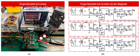
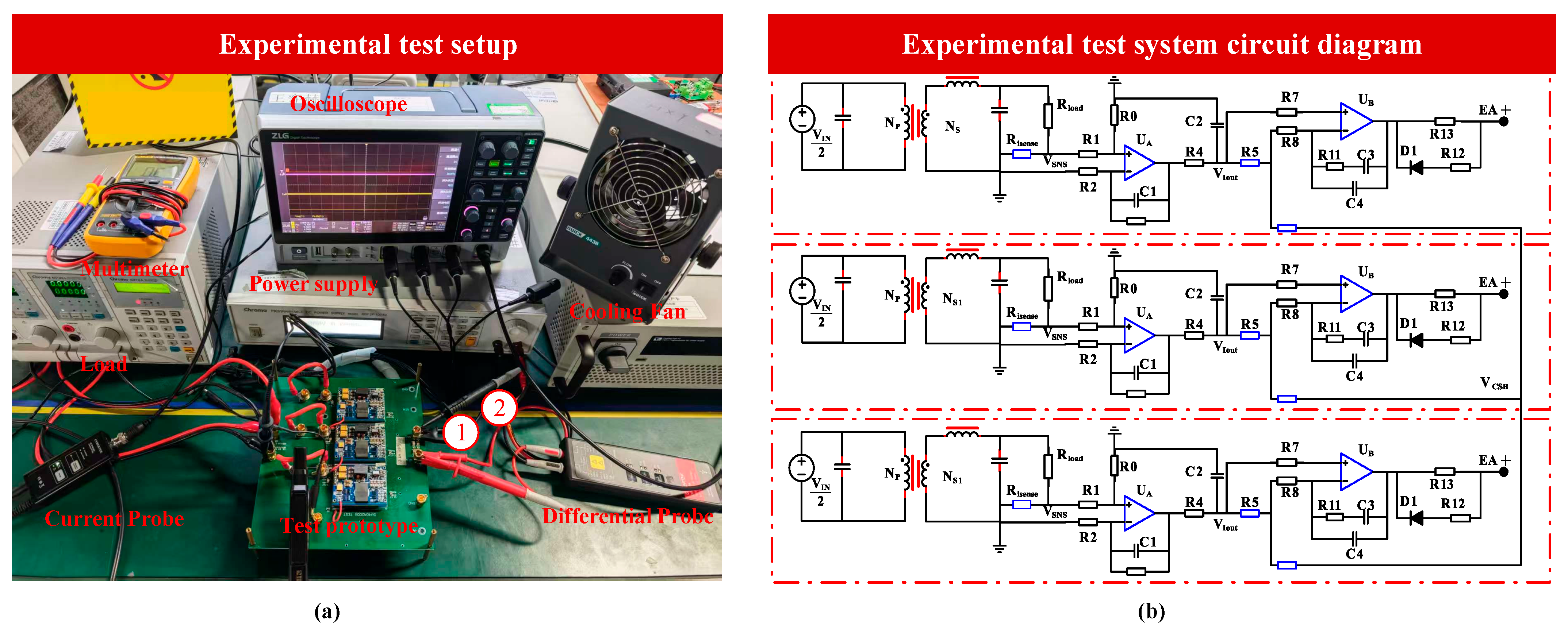
To experimentally evaluate the proposed LAI current-sharing strategy, a three-module parallel half-bridge DC-DC converter prototype was constructed. The experimental prototype and measurement platform are shown in Figure 5a, while the corresponding system-level circuit diagram is provided in Figure 5b. Each converter module includes the half-bridge power stage, transformer and rectification stage, current-sensing circuit, current-sharing error amplifier, and LAI injection interface. The three modules are connected to a common output bus and share a common analog current-sharing bus.
Figure 5.
(a) Experimental prototype and test setup and (b) test system circuit diagram.
The experimental measurements were performed using an oscilloscope ZDS2024B with current and differential-voltage probes, together with a programmable/electronic load Chroma 6310A and DC power supply Chroma 62000P.
The main electrical and control parameters of the prototype are summarized in Table 2.
Table 2.
Table of key parameters.
The converter operates with a 36 V input voltage and a 5 V output voltage. The switching frequency is 300 kHz, and the maximum output current of the parallel system reaches 100 A. Three converter modules are connected in parallel to evaluate the scalability of the proposed architecture. During startup, the diode-based injection interface prevents reverse current from the sharing bus into individual voltage controllers. Therefore, the current-sharing loop remains isolated until the voltage regulation loops enter normal operating conditions. The proposed LAI structure avoids excessive interaction during startup. Compared with conventional active current-sharing methods, the proposed prototype does not require digital communication or additional control processors. The current-sharing function is fully realized through the analog LAI control network.
4.2. Current-Sharing Accuracy Verification
The steady-state current-sharing performance was first evaluated under a 30 A load condition.
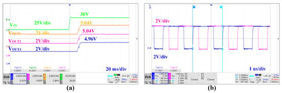
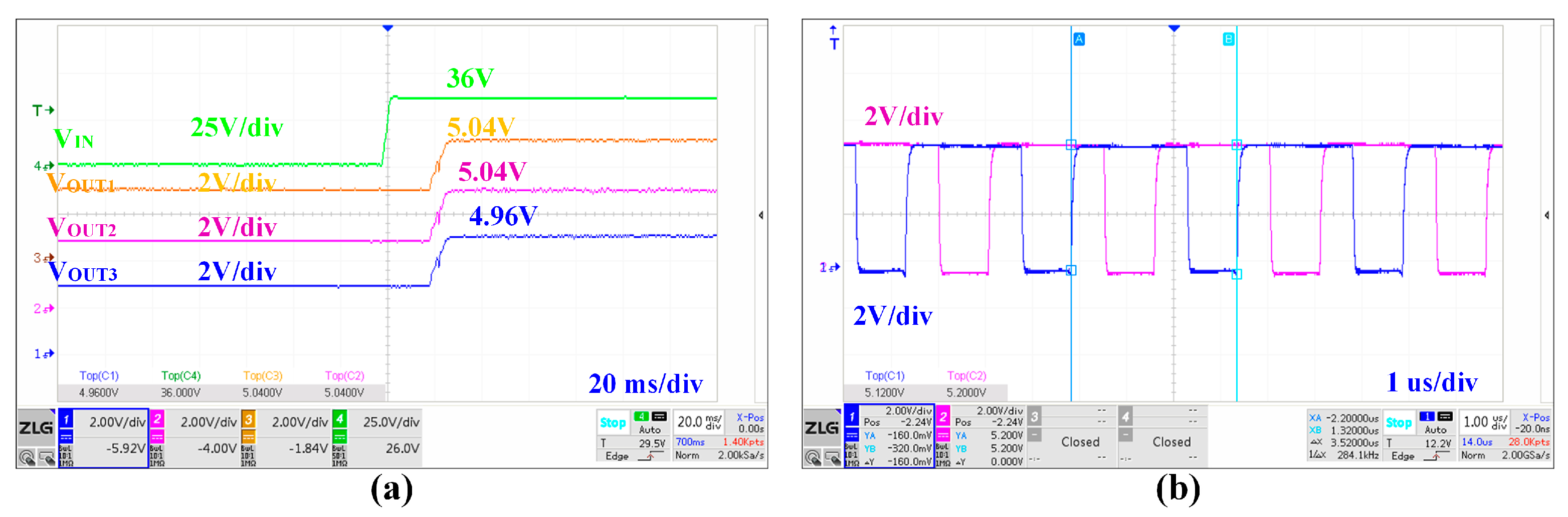
Figure 6a depicts the input and output voltage test waveforms for the modules. The single-module input voltage is 36 V, with Module 1 outputting 4.96 V and Modules 2 and 3 outputting 5.04 V. An offset inconsistency of 80 mV exists in the output voltages, corresponding to approximately 1.6% of the nominal 5 V output voltage. Figure 6b shows the measured gate-drive waveform of the power switches. The experimentally measured switching frequency is approximately 285 kHz, which is distinguished from the nominal design value of 300 kHz listed in Table 2.
Figure 6.
Experimental waveforms: (a) input and output voltages of the converter; (b) measured gate-drive waveform with a switching frequency of approximately 285 kHz.
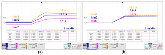
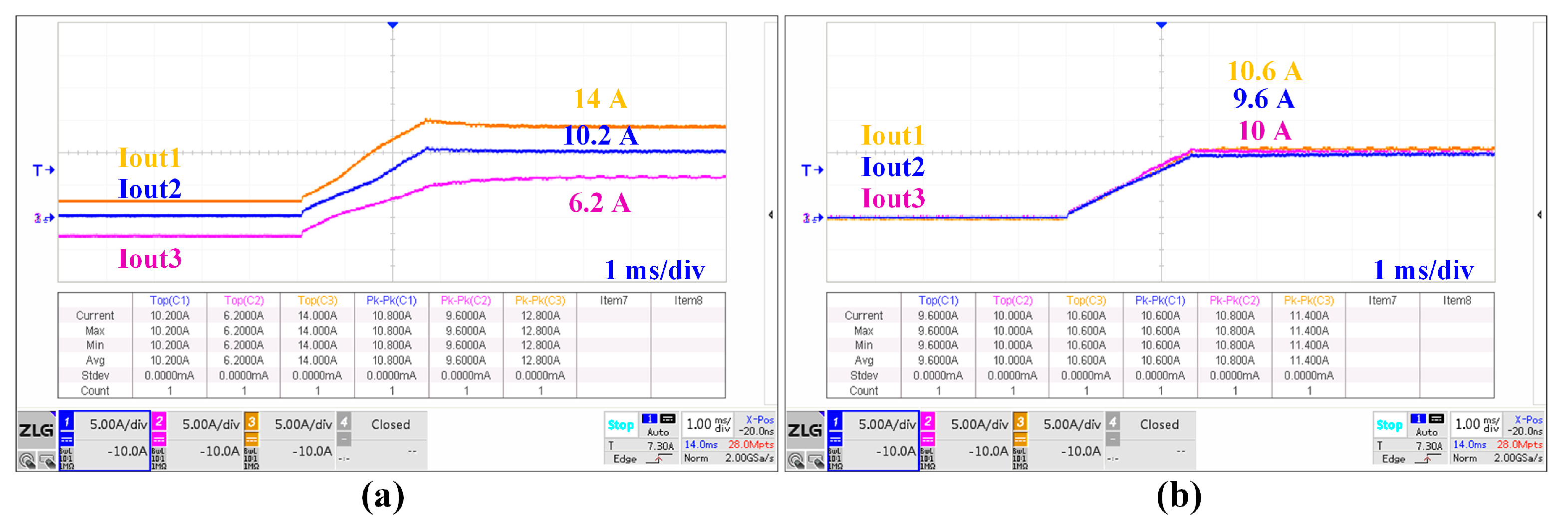
Before activating the proposed current-sharing circuit, the mismatch among converter modules caused significant current imbalance due to intentional reference voltage deviation. As shown in Figure 7a, the output currents of the three modules were significantly different, where Module 2 delivered only 6.2 A while Module 3 supplied 14 A. This imbalance results from the inherent tolerance of converter components and voltage reference circuits. Without compensation, the module with slightly higher output voltage tends to carry excessive current, which may accelerate thermal stress.
Figure 7.
Experimental test (a) without the current-sharing loop. (b) Applying the proposed current-sharing network.
After enabling the proposed LAI current-sharing controller, the output currents converged rapidly, as shown in Figure 7b.
After enabling the proposed LAI current-sharing controller, the measured module currents were approximately 9.6 A, 10.0 A, and 10.6 A. For a total load current of 30 A, the ideal equal-share current is 10 A per module. According to the definition above, the corresponding current deviations are 4.0%, 0%, and 6.0%, respectively, resulting in a maximum current-sharing error of approximately 6.0%. Compared with the severe current imbalance observed before the current-sharing loop was enabled, the proposed LAI strategy significantly improves the current distribution among the three modules.
4.3. Dynamic Current Redistribution Performance
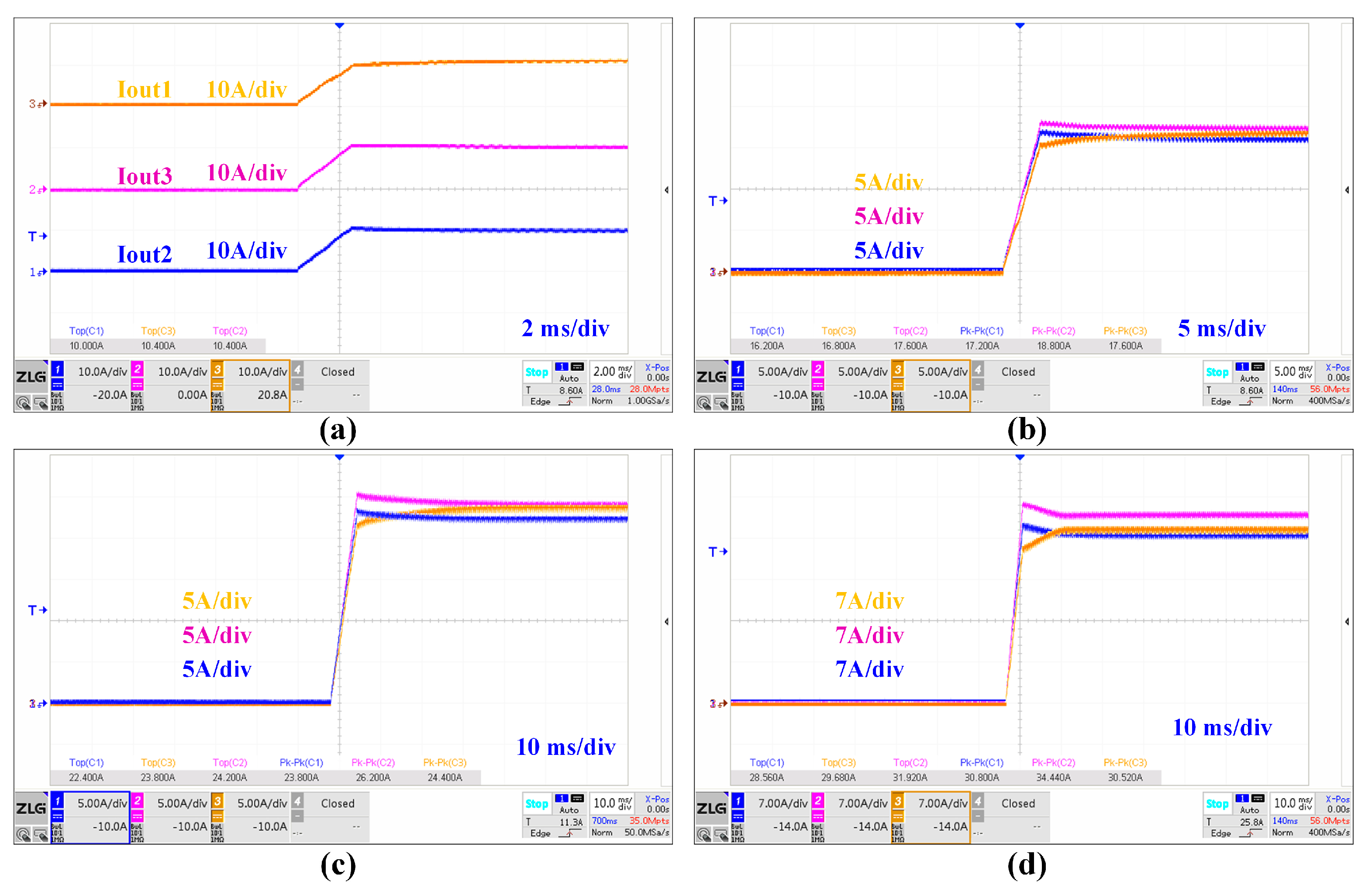
To further evaluate the transient performance, different load conditions were applied to the parallel converter system. The output current was increased from 30 A to 90 A, corresponding to different system loading conditions.
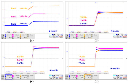
Figure 8 demonstrates the current sharing performance of the three submodules when delivering outputs of 30 A, 50 A, 70 A, and 90 A, respectively. It can be observed that at a total output current of 90 A, the ideal equal-share current is 30 A per module. The measured module currents were approximately 28.56 A, 29.68 A, and 31.92 A, corresponding to individual current deviations of approximately 4.8%, 1.1%, and 6.4%, respectively. Therefore, the maximum current-sharing error under this operating condition is approximately 6.4%.
Figure 8.
Different load currents: (a) 30 A; (b) 50 A; (c) 70 A; (d) 90 A.
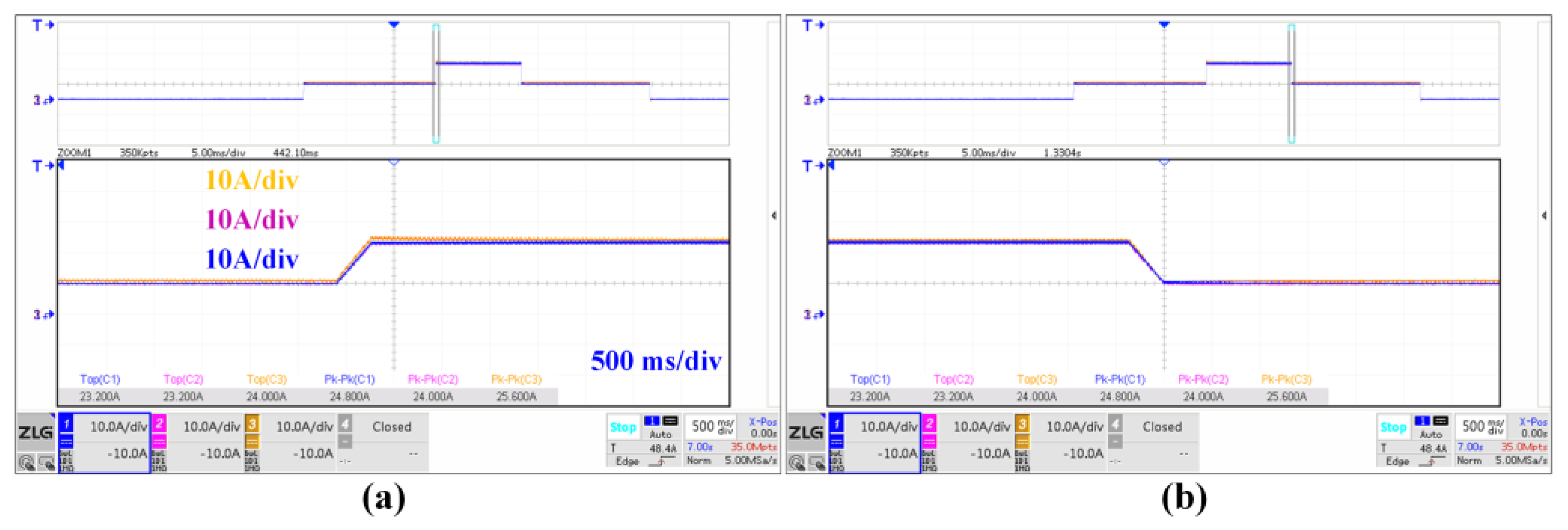
The transient response was further evaluated using load-step tests. A load transition between 30 A and 90 A was applied, as shown in Figure 9.
Figure 9.
Load step test: (a) step rise; (b) step fall.
Figure 9 presents the load-step responses when the total output current is varied between approximately 30 and 90 A. This corresponds to a change in the ideal equal-share current from approximately 10 to 30 A per module. During both the load increase and load decrease, the three branch currents move toward their new steady-state operating points without sustained oscillation.
Small differences in the transient trajectories of the three modules can be observed. These differences are attributed to practical mismatches in current-sensing gain and offset, semiconductor and passive-component tolerances, local voltage-loop characteristics, and PCB parasitic parameters. In addition, because the LAI current-sharing loop is intentionally designed with a lower bandwidth than the primary voltage-regulation loop, the initial transient response is mainly governed by the local voltage controllers, followed by current redistribution through the sharing loop.
4.4. Fault-Tolerant Capability and Thermal Performance
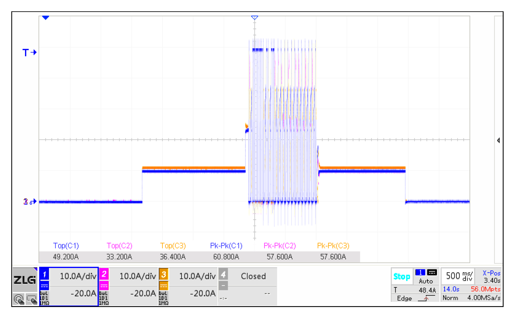
A key objective of the proposed LAI architecture is to improve robustness under current-sharing bus failures. To verify this feature, an intentional short circuit was applied to the current-sharing bus. In conventional high-authority ACS systems, a sharing-bus fault may generate a large correction signal and directly disturb the voltage regulation loop, potentially resulting in abnormal output voltage.
In the proposed architecture, the high-impedance injection resistor limits the maximum correction voltage generated by the sharing loop.
Figure 10 shows the response to an intentional short circuit of the current-sharing bus. During the bus-fault interval, the current-sharing information is disturbed, and the instantaneous current-sharing accuracy deteriorates. Nevertheless, the measured branch currents remain bounded, and the converter continues operating without a sustained unstable current response. After removal of the fault, normal current-sharing operation is recovered.
Figure 10.
Current-sharing fault robustness testing.
This result confirms that the proposed LAI mechanism provides inherent fault isolation capability without requiring additional protection circuits.
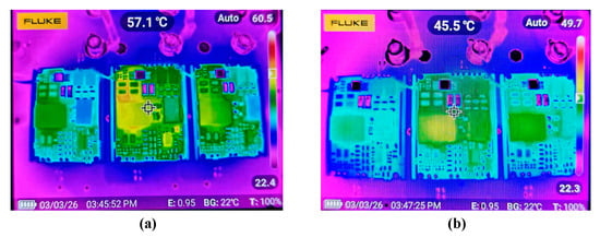
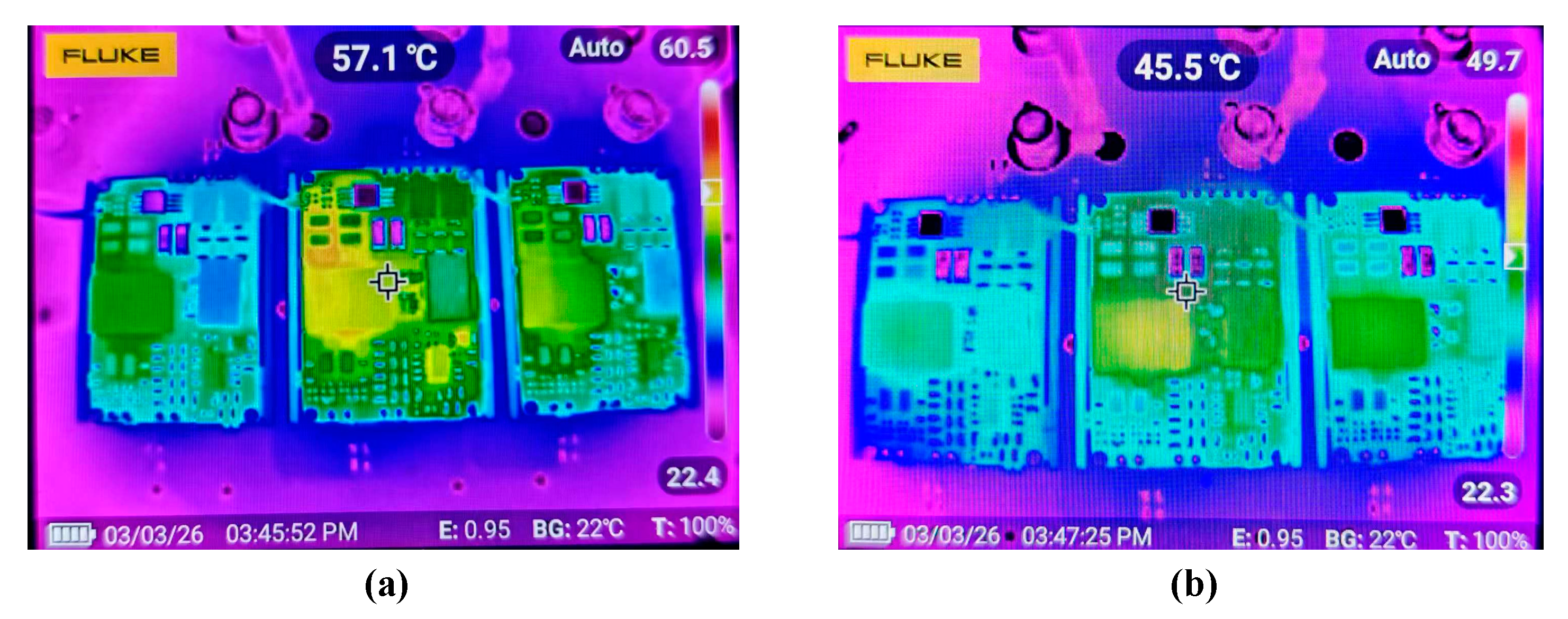
Because current imbalance directly influences power loss distribution, thermal performance is an important factor for parallel converter reliability. The thermal images of the three converter modules under full-load operation are shown in Figure 11.
Figure 11.
Thermal images of the parallel modules under full-load condition: (a) without the current-sharing loop; (b) with the proposed current-sharing network enabled.
As shown in Figure 11, the thermal distribution is noticeably improved after applying the proposed LAI current-sharing strategy. Under the reported full-load operating condition, the temperature at the representative monitored location on the central converter module was approximately 57.1 °C without the current-sharing loop, as shown in Figure 11a. After enabling the proposed current-sharing network, the temperature at the corresponding location decreased to approximately 45.5 °C, corresponding to a reduction of approximately 11.6 °C. The infrared-camera emissivity and background-temperature settings were 0.95 and approximately 22 °C, respectively, for both measurements.
Without current sharing, unequal branch currents result in uneven conduction and switching losses, causing greater thermal stress in the more heavily loaded module. After the LAI current-sharing loop is enabled, the module currents are redistributed, thereby reducing the concentration of power loss and producing a more balanced thermal distribution. It should be noted that the infrared measurements represent surface temperatures rather than semiconductor junction temperatures; therefore, Figure 11 is used as a comparative evaluation of thermal-stress redistribution rather than as an absolute junction-temperature measurement.
5. Discussion
The experimental results demonstrate that the proposed LAI architecture can reduce the current imbalance of the three-module prototype while limiting the direct authority of the auxiliary sharing controller over the primary voltage-reference node. The main distinction of the proposed method is, therefore, not an attempt to maximize current-sharing-loop gain but the intentional limitation and direction-dependent shaping of the interaction between the sharing loop and the primary voltage loop. The piecewise analysis also clarifies that the complete LAI interface cannot be represented by R13 alone. When D1 is blocked, R13 provides a weak high-impedance coupling path. When D1 conducts, the D1-R12 branch modifies both the effective injection gain and the reference-node equilibrium. Accordingly, the approximately 1.9% value obtained from R13 = 510 kΩ and Req ≈ 10 kΩ should be interpreted as the diode-off small-signal injection factor rather than as a global nonlinear authority limit.
From a system perspective, the modal analysis shows that an ideal average-current-sharing controller responds to differential current components but not to a pure common-mode current variation. The common mode remains primarily governed by the converter voltage loops and common output-bus impedance, whereas the LAI current-sharing controller introduces feedback into the N-1 differential modes. This interpretation is more appropriate for scalability analysis than treating (N-1)/N as a universal scalar loop-gain multiplier.
Table 3 summarizes the principal characteristics of representative current-sharing approaches. The comparison is based on their control architectures and the literature rather than on identical-hardware experiments. A complete experimental benchmark would require implementation and retuning of several alternative controllers on the same power stage. Such a comparison was not available within the present experimental campaign, and, therefore, no claim is made that the proposed method has universally better efficiency, transient settling time, or absolute sharing accuracy than all conventional techniques.
Table 3.
Qualitative comparison of current-sharing strategies.
Several limitations of the present work should be emphasized. First, the experimental comparison is limited to operation with and without the proposed sharing loop; identical-hardware tests against droop, master–slave, and conventional high-authority average-current-sharing controllers were not performed. Second, a dedicated efficiency comparison was not recorded, and no efficiency-superiority claim is, therefore, made. Third, a controlled simultaneous-startup experiment and a dedicated nonlinear saturation-recovery test were not included in the present measurement campaign. Finally, the analytical modal decomposition assumes nominally identical modules. Extension to heterogeneous converters and experimental identification of the full multi-module impedance model will be considered in future work.
6. Conclusions
This study proposes a fault-tolerant low-authority injection (LAI) current-sharing strategy for parallel DC-DC converters. The proposed method limits the influence of the current-sharing loop on the primary voltage-regulation loop through a high-impedance resistor–diode injection interface, thereby improving fault robustness while maintaining effective current redistribution. A three-module 36 V/5 V prototype was experimentally evaluated. At a total output current of 30 A, the three module currents were 9.6, 10.0, and 10.6 A, corresponding to a maximum individual deviation of approximately 6.0% from the ideal equal-share current. At 90 A, the measured module currents were 28.56, 29.68, and 31.92 A, with a maximum individual deviation of approximately 6.4%. In addition, the converter maintained stable operation during an intentional current-sharing-bus short-circuit test. These results demonstrate that the proposed LAI architecture provides a simple and hardware-oriented solution that balances current-sharing capability and fault tolerance for parallel DC-DC converter systems.
Author Contributions
Conceptualization, B.Z. (Baoping Zhang) and D.B.; methodology, X.L. and C.X.; software, X.L. and C.X.; formal analysis, B.Z. (Bin Zhao); investigation, B.Z. (Bin Zhao); writing—original draft preparation, B.Z. ( Baoping Zhang) and D.B. All authors have read and agreed to the published version of the manuscript.
Funding
This research received no external funding.
Data Availability Statement
The data presented in this study are available on request from the corresponding author. The data are not publicly available due to the data are part of an ongoing study or due to technical.
Conflicts of Interest
The authors declare no conflicts of interest.
Abbreviations
The following abbreviations are used in this manuscript:
| CSB | Current-sharing bus |
| EV | Electric vehicle |
| PCB | Printed circuit board |
| PoL | Point of Load |
| ACS | Average Current Sharing |
| DCR | DC Resistance |
| CSEA | current-sharing error amplifier |
| LAI | Low-Authority Injection |
References
- Ding, S.; Wang, P.; Wang, W.; Xu, D.; Blaabjerg, F. Current sharing behavior of parallel connected silicon carbide MOSFETs influenced by parasitic inductance. In Proceedings of the 2019 10th International Conference on Power Electronics and ECCE Asia (ICPE 2019–ECCE Asia), Busan, Republic of Korea, 27–30 May 2019; pp. 2846–2852. [Google Scholar]
- Ba, D.; Yu, F.; Wang, Y.; Chen, X.; Niu, Y.; Lyu, X. Optimization Study of Parasitic Parameters in Parallel Interleaved Windings for High-Frequency PCB Transformers. IEEE Trans. Power Electron. 2025, 40, 14894–14907. [Google Scholar] [CrossRef] [Scilit]
- Xiao, Y.; Liu, Q.; Tang, Y.; Du, L.; Ma, H. Current sharing model of parallel connected IGBTs during turn-on. In Proceedings of the IECON 2014—40th Annual Conference of the IEEE Industrial Electronics Society, Dallas, TX, USA, 29 October–1 November 2014. [Google Scholar]
- Ba, D.; Lyu, X.; Wang, Y.; Chen, X.; Niu, Y. Comparative study of the effects of HFT(PCB) parasitics on single-ended forward DC/DC converters. IEICE Electron. Express 2024, 21, 20240380. [Google Scholar] [CrossRef] [Scilit]
- Yuan, T.; Jin, F.; Li, Z.; Li, Q. Current sharing analysis of a high power transformer with parallel windings. In Proceedings of the 2023 IEEE Applied Power Electronics Conference and Exposition (APEC), Orlando, FL, USA, 19–23 March 2023. [Google Scholar]
- Pan, C.-T.; Liao, Y.-H. Modeling and control of circulating currents for parallel three-phase boost rectifiers with different load sharing. IEEE Trans. Ind. Electron. 2008, 55, 2776–2785. [Google Scholar] [CrossRef] [Scilit]
- Xu, S.; Cao, W.; Liu, K.; Wang, S.; Zhao, J. Analysis and control of switching circulating currents in multi-module parallel SPWM converters. IEEE Access 2018, 6, 32637–32648. [Google Scholar] [CrossRef] [Scilit]
- Javed, K.; De Croo, R.; Vandevelde, L.; De Belie, F. Circulating current control in interleaved and parallel connected power converters. Machines 2023, 11, 878. [Google Scholar] [CrossRef] [Scilit]
- Son, Y.-K.; Chee, S.-J.; Lee, Y.; Sul, S.-K.; Lim, C.; Huh, S.; Oh, J. Suppression of circulating current in parallel operation of three-level converters. In Proceedings of the 2016 IEEE Applied Power Electronics Conference and Exposition (APEC), Long Beach, CA, USA, 20–24 March 2016; p. 2370. [Google Scholar]
- Song, C.; Zhao, R.; Zeng, Z.; Zhu, M.; Cai, H. Circulating current elimination scheme for parallel operation of common DC bus inverters. Int. J. Electr. Power Energy Syst. 2014, 63, 17–29. [Google Scholar] [CrossRef] [Scilit]
- Fu, X.; Wang, H.; Guo, X.; Shi, C.; Jia, D.; Chen, C.; Guerrero, J.M. A novel circulating current suppression for paralleled current source converter based on virtual impedance concept. Energies 2022, 15, 1952. [Google Scholar] [CrossRef] [Scilit]
- Xu, J.; Wang, K.; Deng, C. Circulating current suppression for parallel modular energy storage converter based on improved single neuron PID. IOP Conf. Ser. Mater. Sci. Eng. 2019, 592, 012099. [Google Scholar] [CrossRef] [Scilit]
- Shebani, M.M.; Iqbal, T.; Quaicoe, J.E. Modified droop method based on master current control for parallel-connected DC-DC boost converters. J. Electr. Comput. Eng. 2018, 2018, 9819787. [Google Scholar] [CrossRef] [Scilit]
- Ba, D.; Chen, G.; Li, P.; An, K.; Liu, X. Fuzzy Smith predictor–based active disturbance rejection controller for time-delay systems with application to drilling stick–slip vibration control. Proc. Inst. Mech. Eng. Part I J. Syst. Control Eng. 2023, 237, 401–414. [Google Scholar] [CrossRef] [Scilit]
- Nduwamungu, A.; Lie, T.T.; Lestas, I.; Nair, N.-K.C.; Gunawardane, K. Decentralized voltage regulation and accurate current sharing in parallel buck converters with optimized piecewise linear droop control. In Proceedings of the 2024 18th International Conference on Probabilistic Methods Applied to Power Systems (PMAPS), Auckland, New Zealand, 24–26 June 2024; pp. 1–6. [Google Scholar]
- Panov, Y.; Rajagopalan, J.; Lee, F.C. Analysis and design of N paralleled DC-DC converters with master-slave current-sharing control. In Proceedings of the APEC ’97—Applied Power Electronics Conference, Atlanta, GA, USA, 23–27 February 1997; Volume 1, pp. 436–442. [Google Scholar]
- Rajagopalan, J.; Xing, K.; Guo, Y.; Lee, F.C.; Manners, B. Modeling and dynamic analysis of paralleled DC/DC converters with master-slave current sharing control. In Proceedings of the Applied Power Electronics Conference (APEC ’96), San Jose, CA, USA, 3–7 March 1996; Volume 2, pp. 678–684. [Google Scholar]
- Mazumder, S.K.; Tahir, M.; Acharya, K. Master–slave current-sharing control of a parallel DC–DC converter system over an RF communication interface. IEEE Trans. Ind. Electron. 2008, 55, 59–66. [Google Scholar] [CrossRef] [Scilit]
- Jovanovic, M.M.; Crow, D.E.; Lieu, F.-Y. A novel, low-cost implementation of “democratic” load-current sharing of paralleled converter modules. IEEE Trans. Power Electron. 1996, 11, 604–611. [Google Scholar] [CrossRef]
- Gong, B.; Liu, K.; Luan, H.; Wu, J.; Zhou, J.; Tan, S.; Huang, C.; Wu, H. Design of a dynamic hybrid compensator for current sharing control of parallel phase-shifted full-bridge converter. Energies 2023, 16, 2204. [Google Scholar] [CrossRef] [Scilit]
- Zhang, F.; Ma, Y.; Lu, H.; Cai, R.; Zhao, Z. Research on current sharing method of two-phase parallel Sigma converter. In Proceedings of the 2021 IEEE 12th Energy Conversion Congress & Exposition—Asia (ECCE-Asia), Singapore, 24–27 May 2021; pp. 379–384. [Google Scholar]
- Klassen, S.V.; Klassen, T.S.; Luft, S.V. Current sharing in digitally controlled DC-DC converters connected in parallel. In Proceedings of the 2019 20th International Conference of Young Specialists on Micro/Nanotechnologies and Electron Devices (EDM), Erlagol, Russia, 29 June–3 July 2019; pp. 541–546. [Google Scholar]
- Zhang, Y.; Yu, M.; Liu, F.; Kang, Y. Instantaneous current-sharing control strategy for parallel operation of UPS modules using virtual impedance. IEEE Trans. Power Electron. 2013, 28, 432–440. [Google Scholar] [CrossRef] [Scilit]
- Lee, C.S.; Kim, S.; Kim, C.B.; Hong, S.C.; Yoo, J.S.; Kim, S.W.; Kim, C.; Woo, S.H.; Sun, S.Y. Parallel UPS with an instantaneous current sharing control. In Proceedings of the IECON ’98—24th Annual Conference of the IEEE Industrial Electronics Society, Aachen, Germany, 31 August–4 September 1998; Volume 1, pp. 568–573. [Google Scholar]
- Chang, E.C.; Lin, G.W.; Lin, Y.T.; Mao, K.C.; Wu, R.C. Control design of parallel-connected PWM DC-AC converters for sustainable energy applications. J. Phys. Conf. Ser. 2021, 2020, 012015. [Google Scholar] [CrossRef] [Scilit]
- Ba, D.; Wang, Y.; Cao, Q.; Lyu, X. Design of a Novel Cascaded Point-of-Load Power Converter with Reduced Sensitivity to Component Parameter Variations. Energies 2026, 19, 3317. [Google Scholar] [CrossRef] [Scilit]
- Allam, A.M.; Ibrahim, A.S.; Nabil, E. Single loop PID controller design based on optimization algorithms for parallelly connected DC-DC converters. J. Phys. Conf. Ser. 2021, 2128, 012027. [Google Scholar] [CrossRef] [Scilit]
- Tang, W.; Wang, H.; Zhu, X.; Mo, W.; Gao, W.; Yue, X. The analysis of current sharing effect for two-unit paralleled common capacitor LLC resonant converter. IEEE Trans. Ind. Electron. 2023, 70, 2178–2188. [Google Scholar] [CrossRef] [Scilit]
- Delpoux, R.; Trégouët, J.-F.; Gauthier, J.-Y.; Lacombe, C. New framework for optimal current sharing of nonidentical parallel buck converters. IEEE Trans. Control Syst. Technol. 2019, 27, 1237–1243. [Google Scholar] [CrossRef] [Scilit]
- He, L.; Zeng, T. Interleaved parallel high step-up DC-DC converter with cross-coupled inductors for low current/voltage ripple and auto-current sharing. IEEJ Trans. Electr. Electron. Eng. 2021, 16, 787–797. [Google Scholar]
- Saddriwala, M.A.; Alam, M. Artificial neural network based decentralized current-sharing control for parallel connected DC-DC converters in DC microgrid application. Comput. Electr. Eng. 2024, 120, 109731. [Google Scholar] [CrossRef] [Scilit]
- Liang, Z.; Chung, C.Y.; Zhang, W.; Wang, Q.; Lin, W.; Wang, C. Enabling high-efficiency economic dispatch of hybrid AC/DC networked microgrids: Steady-state convex bi-directional converter models. IEEE Trans. Smart Grid 2025, 16, 45–61. [Google Scholar] [CrossRef] [Scilit]
- Sahoo, H.; Kapat, S.; Singh, B. Small-signal modeling and analysis of converter interactivity in 48 V DC grid. IEEE Trans. Ind. Appl. 2023, 59, 5622–5632. [Google Scholar] [CrossRef] [Scilit]

Disclaimer/Publisher’s Note: The statements, opinions and data contained in all publications are solely those of the individual author(s) and contributor(s) and not of MDPI and/or the editor(s). MDPI and/or the editor(s) disclaim responsibility for any injury to people or property resulting from any ideas, methods, instructions or products referred to in the content. |
© 2026 by the authors. Licensee MDPI, Basel, Switzerland. This article is an open access article distributed under the terms and conditions of the Creative Commons Attribution (CC BY) license.