


Abstract
In the field of new-energy electric vehicles, lithium battery cells need to be connected in series and parallel to meet the requirements of high voltage and high power. Aiming at the high cost of traditional active equalizer, a half/full-bridge converter is developed, which integrates lithium battery equalization technology into the auxiliary power module of an electric vehicle. The asymmetric modulation strategy is realized by introducing DC duty ratio adjustment at the half-bridge side to improve the balancing speed. In order to suppress the backflow power of the whole bridge side, an extended phase-shift control strategy is proposed based on the single-phase-shift control strategy. The working principle and mode of the half/full-bridge converter under the proposed control strategy are analyzed, and the mathematical models of transmission power and reflux power of the converter under the two control strategies are compared. The experiments show that the modular half/full-bridge converter functions using lithium battery equalization and an auxiliary power module; they also verify the correctness of the proposed extended phase-shift control strategy.
1. Introduction
At present, the voltage range of high-voltage platforms in new-energy electric vehicles is typically between 200 V and 400 V. To meet the requirements of high-voltage and high-power applications, a large number of lithium-ion battery cells must be connected in series and parallel [1,2,3]. However, owing to non-uniform material distribution and variations in manufacturing processes, individual lithium-ion battery cells exhibit inconsistencies in performance parameters such as equivalent internal resistance and initial capacity [4,5]. To address this issue, lithium-ion battery equalizers have become essential components of battery management systems [6]. Although lithium-ion battery equalizers can be classified in various ways, they can generally be divided into passive equalizers and active equalizers [7,8,9,10]. Conventional active equalization circuits are currently used only in some high-end new-energy electric vehicles because of their complex control and relatively high cost [11,12,13].
In electric vehicles, the step-down converter that transfers power from the high-voltage battery pack—referred to as the high-voltage side (HV)—to the low-voltage load side (LV) is known as an auxiliary power module (APM). The LV loads mainly include lighting systems, windshield wipers, electric compressors, and other devices, which generally operate under low-voltage and high-rated-current conditions. Therefore, integrating an active equalizer into the APM and modularly replacing the original step-down converter with multiple low-rated-power converters can reduce the cost of the active equalizer while retaining the conventional functions of the APM. This integration merges the auxiliary power conversion and active equalization into one modular hardware platform, eliminating the requirement for an independent dedicated active equalizer board and reducing overall system hardware cost.
Reference [14] discusses the application of a dual-active-bridge (DAB) converter in an APM. This converter achieves both battery equalization and voltage conversion. However, each converter requires eight switching devices, and each battery cell must be equipped with an individual DAB converter, resulting in a relatively high cost. Since the HFB converter integrates two battery cells, the number of switching devices required per single battery cell is significantly reduced [15]. Furthermore, compared with the bidirectional forward converter, flyback converter and push–pull converter, the HFB converter can achieve soft-switching over most of its operating range and exhibits high efficiency. Therefore, the HFB converter possesses favorable application prospects. Nevertheless, this simplified structure introduces coupling between the energy flows of the two cells and therefore requires more precise control.
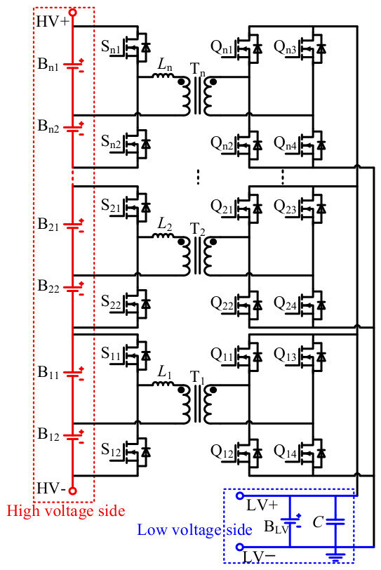
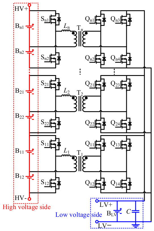
Figure 1 shows the topology of an APM with lithium-ion battery equalization capability constructed using modular HFB converters. Each module can achieve bidirectional energy transfer between the high- and low-voltage sides through a phase-shift control strategy. In addition, the two battery cells within each module can be directly equalized through the half-bridge circuit. Equalization among battery packs belonging to different modules is achieved by using the LV-side battery as an intermediate energy-storage element. However, under the conventional symmetrical modulation strategy, the equalization current in the half-bridge is dependent on the voltage difference between the battery cells [15]. The equalization process becomes relatively slow when the cell-voltage difference is small. Consequently, energy transfer between battery cells within the half-bridge requires an appropriate control scheme for regulation. In addition, the control strategies for the DAB include the single-phase-shift (SPS) control strategy and the extended-phase-shift (EPS) control strategy. The SPS strategy suffers from high backflow power, which results in low efficiency. By contrast, the EPS control features low backflow power and high efficiency. Nevertheless, many challenges still remain to be resolved when combining the EPS strategy of DAB with the energy transfer control for cells within the half-bridge.
Figure 1.
APM structure composed of modular HFB converters.
To address the aforementioned issues, a DC-adjustable duty cycle is introduced on the half-bridge side to implement an asymmetric modulation strategy and thereby accelerate the equalization process. Based on this topology, an extended phase-shift control strategy is proposed [16,17,18,19,20] to suppress power backflow on the full-bridge side and reduce circuit losses. Experimental results verify the effectiveness of the proposed control strategies and the validity of the four operating modes.
Different from existing HFB-based auxiliary power modules adopting symmetric modulation, this paper introduces DC-adjustable asymmetric modulation on the half-bridge side to accelerate equalization under small cell-voltage difference. Moreover, extended phase-shift control is applied for the full-bridge side of an HFB converter to suppress backflow power. The combination of half-bridge asymmetric modulation and full-bridge EPS control constitutes the main innovation of this manuscript.
2. Characteristic Analysis of the Half-Bridge–Full-Bridge Converter
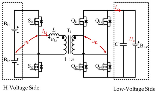
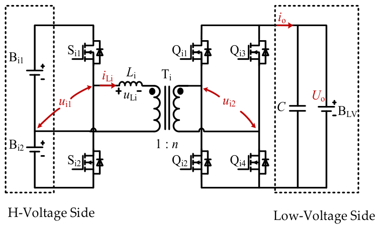
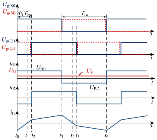
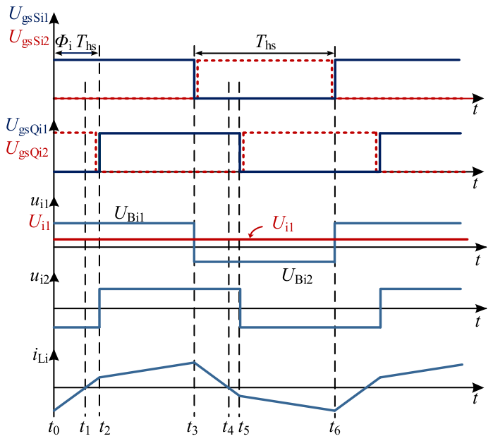
Figure 2 shows the topology of a single HFB converter. The transformer primary side consists of battery cells, an auxiliary inductor, and a half-bridge circuit, whereas the secondary side consists of a full-bridge circuit, a filter capacitor, and a 12 V battery. The operating waveforms of the HFB converter under the single-phase-shift control strategy are shown in Figure 3, where Φi denotes the phase-shift ratio; ui1 and ui2 (i = 1, 2, …, n) denote the AC-side voltages of the half-bridge and full-bridge circuits, respectively; and iLi denotes the auxiliary-inductor current. When ui1 leads ui2, the battery cells on the high-voltage side simultaneously deliver power to the low-voltage side. For simplicity, only the forward operating mode of the HFB converter is analyzed in this paper, since the reverse operating mode can be analyzed in a similar manner.
Figure 2.
HFB converter topology.
Figure 3.
Operational waveforms of HFB converter under single-phase-shift control strategy.
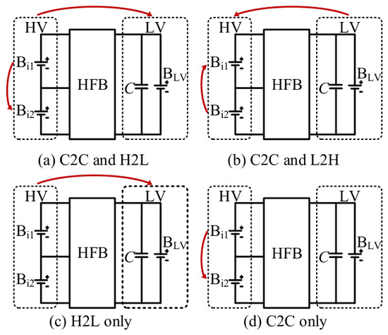
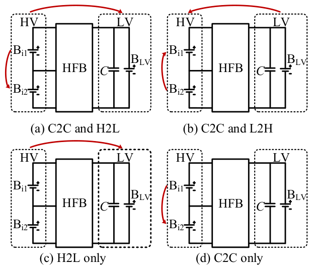
Under the single-phase-shift control strategy, the HFB converter can operate in the four modes shown in Figure 4. Accordingly, the energy-transfer paths of the modular HFB converter, i.e., the APM, include the following: (1) energy exchange between cells within the same module, namely between battery cells Bi1 (i = 1, 2,…, n) and Bi2 connected to the same half-bridge circuit; (2) energy exchange between the high-voltage and low-voltage sides, namely between the battery pack formed by the series-connected cells Bi1 and Bi2 and the low-voltage battery BLV; and (3) energy exchange between cells in different modules, namely between the two battery cells connected to one half-bridge circuit and the two cells connected to any other half-bridge circuit.
Figure 4.
Energy flow diagram of HFB converter under different operating modes.
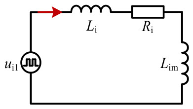
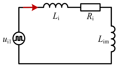
Figure 5 shows the equivalent circuit of the half-bridge side of the HFB converter and its operating waveforms under the single-phase-shift control strategy. Li, Ri, and ui1 denote the auxiliary inductance, equivalent line impedance, and AC-side voltage of the half-bridge circuit, respectively, while Lim denotes the magnetizing inductance of the transformer.
Figure 5.
Half-bridge side equivalent circuit of HFB converter.
Under the conventional symmetrical modulation strategy, the two switching devices on the half-bridge side operate complementarily with a duty cycle of 0.5. When the voltages of the two battery cells within the half-bridge are unequal, ui1 contains a DC component and an AC component, denoted by Ui1 and ui1, respectively, which can be expressed as Equation (1).
Furthermore, in Equation (1),
where Ai1 = UBi1 + UBi2. Similarly, the current iLi also consists of a DC component ILi and an AC component iacLi, the relevant Equations (4) and (5) are shown below.
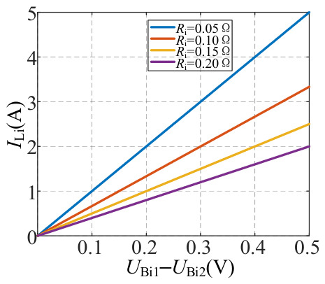
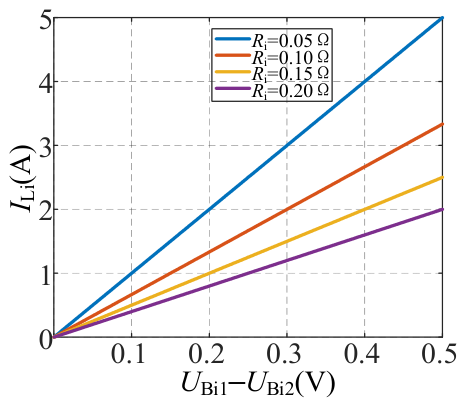
Based on Equation (5), the relationship between the DC component in the half-bridge circuit and the voltage difference between the battery cells is plotted in Figure 6. It can be observed that, for a given Ri, the equalization process between the battery cells within the half-bridge is relatively slow when the cell-voltage difference is small.
Figure 6.
Relationship curve of DC component in half-bridge and voltage difference in battery cells.
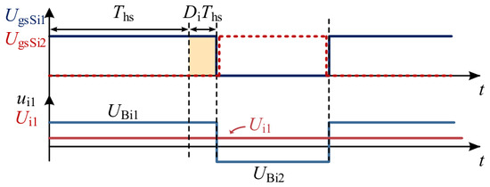
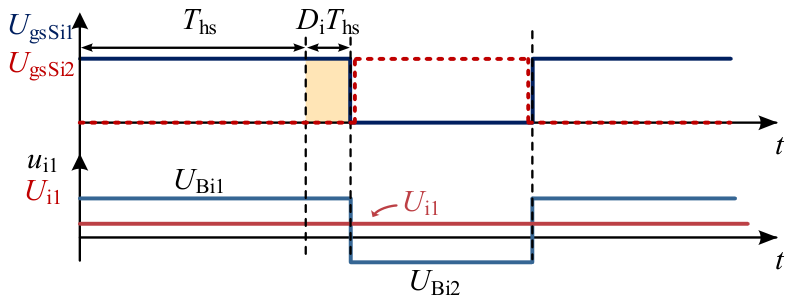
To address the aforementioned issue, an asymmetric modulation strategy is adopted on the half-bridge side of the HFB converter. The corresponding switching waveforms are shown in Figure 7, where Di (i = 1, 2, …, n) denotes the DC adjustment duty cycle. According to Equations (1)–(5), under the asymmetric modulation strategy, the DC components of ui1 and iLi can be expressed as follows:
Figure 7.
Main waveforms under asymmetric modulation strategy.
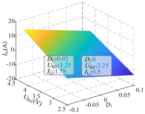
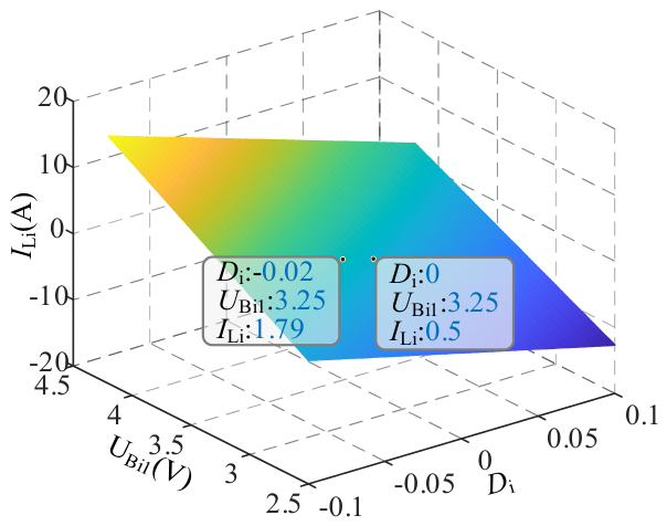
Let Ri = 0.05 Ω, UBi2 = 3.2 V, based on Equation (6), the relationships of the equalization current in the half-bridge with the voltage of battery cell Bi1 and the DC adjustment duty cycle Di are plotted in Figure 8. As can be seen, under the conventional symmetrical modulation strategy, when the voltage difference between adjacent battery cells is 0.05 V, ILi is only 0.5 A. Moreover, the equalization rate decreases significantly as the cell-voltage difference decreases. With the asymmetric modulation strategy, an appropriate DC adjustment duty cycle Di can be introduced according to the actual cell-voltage difference. Consequently, a relatively large equalization current can still be obtained even when the voltage difference is small, thereby increasing the equalization rate between the battery cells within the half-bridge.
Figure 8.
Relationship between DC component and battery cell voltage.
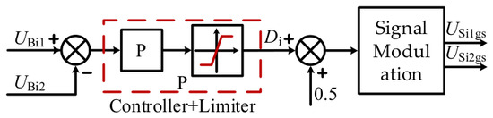
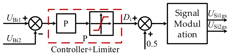
Since the voltage of a lithium-ion battery changes relatively slowly, the asymmetric modulation strategy of the HFB converter can be implemented using a proportional controller and a limiter. Figure 9 shows the asymmetric modulation control scheme, in which the voltages of the two battery cells are used as the reference and comparison values, respectively. The maximum and minimum values of the DC adjustment duty cycle are constrained by the limiter to ensure safe operation of the converter.
Figure 9.
Asymmetric modulation strategy diagram.
It should be noted that asymmetric modulation produces a DC offset component for the transformer’s primary magnetizing current. An excessive DC component may lead to magnetic-core saturation. In this paper, the limiter in Figure 9 restricts DC adjustment duty ratio within Di (0.47~0.53), which confines the DC component of magnetizing current below 2 A to avoid transformer saturation. The duty-cycle limit simultaneously considers two constraints: transformer core anti-saturation requirement and maximum allowable equalization current for lithium-ion cells to prevent over-stress of battery cells.
The proportional gain kp = 3 is determined by the duty-cycle limit Di (0.47~0.53) and the cell-voltage-difference threshold 0.0105 V, following kp = (0.5−0.47)/(0.01) = 3, where Ri = 0.01 Ω. A limiter constrains DC adjustment duty ratio. The PI controller is not adopted. Because of the slow voltage dynamics of lithium-ion cells, PI would hold the duty cycle in saturation and trigger oscillation near voltage-balance point.
3. Extended Phase-Shift Control Strategy
Under the conventional single-phase-shift control strategy, the HFB converter can achieve bidirectional power transfer between the high- and low-voltage sides, thereby fulfilling the function of an auxiliary power module. However, when none of the battery cells requires equalization, i.e., in the H2L-only mode, considerable power backflow occurs on the full-bridge side of the converter. To improve the operating efficiency of the converter, an extended phase-shift (EPS) control strategy is proposed for the full-bridge side based on the circuit configuration of the HFB converter. Owing to the galvanic isolation provided by the transformer, the DC component generated in the half-bridge cannot be transferred to the full-bridge side. Therefore, the asymmetric modulation strategy and the proposed EPS control strategy can be implemented independently.
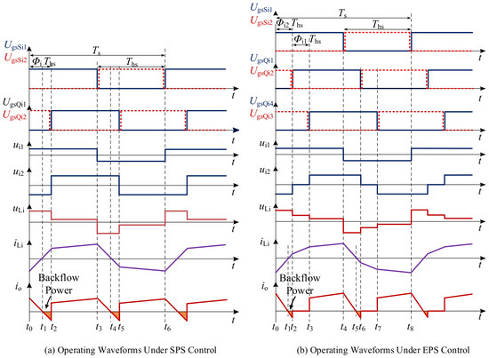
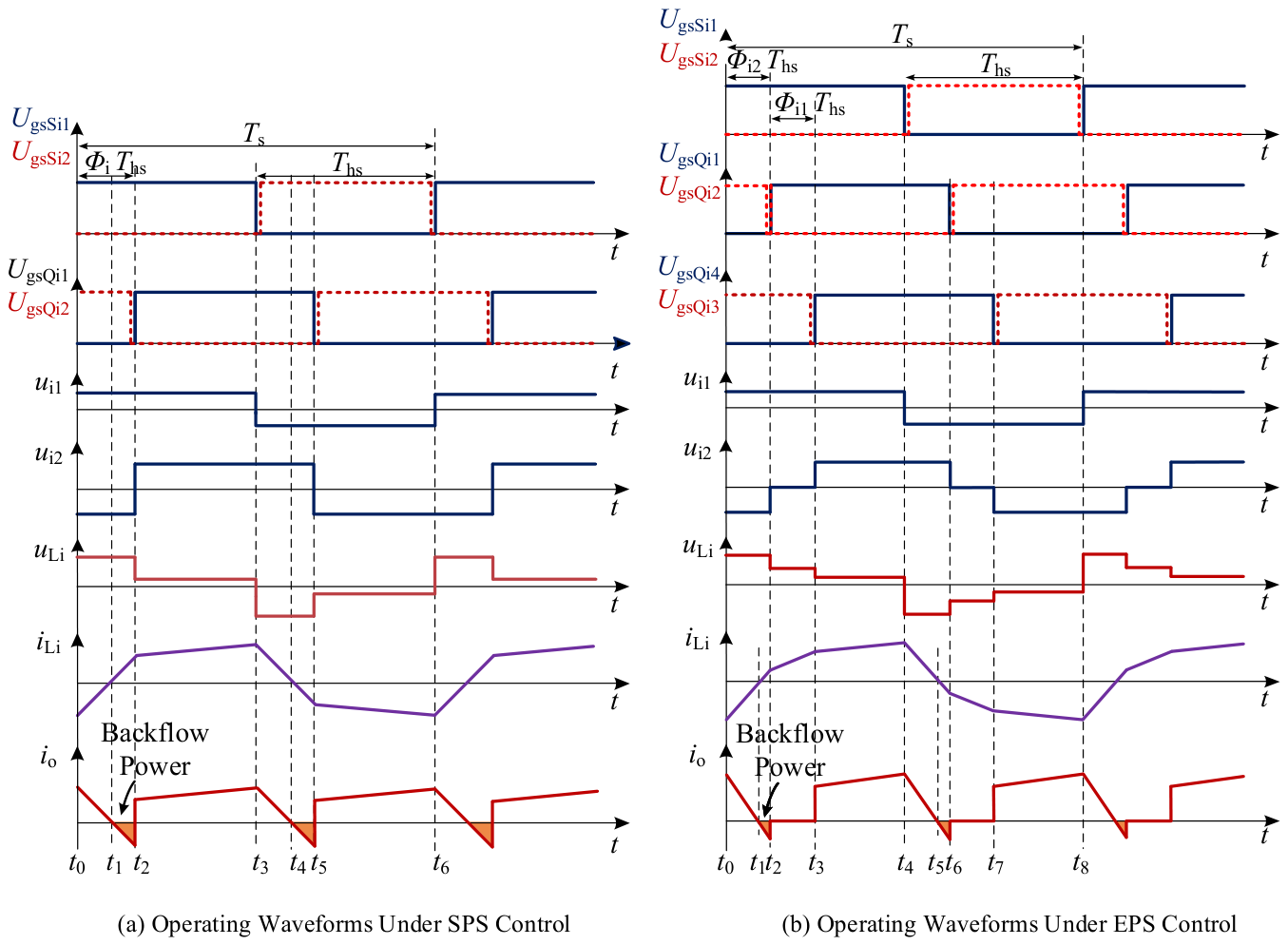
When battery equalization is not required, the operating waveforms of the HFB converter under the two phase-shift control strategies are shown in Figure 10. Figure 10a shows that, under the SPS control strategy, bidirectional power transfer between ui1 and ui2 is regulated by the phase-shift ratio Φi. Compared with the conventional SPS control strategy, the EPS control strategy introduces an additional phase-shift ratio on the full-bridge side, thereby providing the HFB converter with two phase-shift degrees of freedom and improving the flexibility of phase-shift control.
Figure 10.
Operational waveforms of HFB converter under different control strategies.
Figure 10b shows the operating waveforms of the HFB converter under the EPS control strategy. The two switches on the half-bridge side operate complementarily with a duty cycle of 0.5. On the full-bridge side, Φi2 denotes the outer phase-shift ratio between switch Qi1 and the half-bridge switching waveform, while Φi1 denotes the inner phase-shift ratio between switches Qi1 and Qi4. In the following analysis, the ranges of the two phase-shift ratios are defined as 0 < Φi2 < 1, Φi1 + Φi2 < 1.
According to Figure 10a, under the SPS control strategy, the inductor current iLi during different time intervals can be expressed as follows:
According to the symmetry of the inductor current, , expressions for the inductor current at the respective time instants during the first half of the switching period can be derived as follows:
By combining Equations (7) and (8), the output power of the HFB converter under the SPS control strategy can be expressed as follows:
where . Taking the maximum forward-transmission power as the base value, the transferred power under the SPS control strategy is normalized as follows:
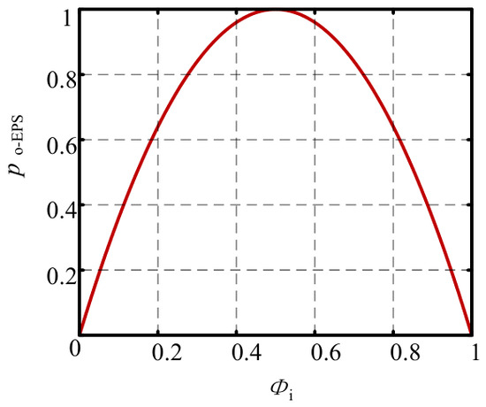
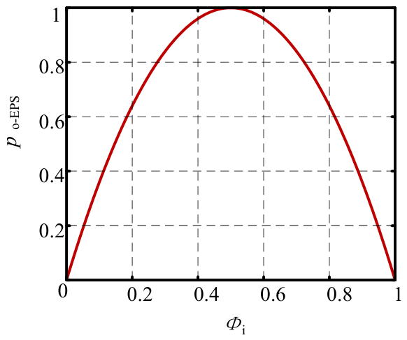
Based on Equation (10), the relationship between the transferred power and the phase-shift ratio is plotted in Figure 11. It can be observed that the forward-transmission power of the HFB converter reaches its maximum when the phase-shift ratio is . When , the transferred power is proportional to the phase-shift ratio, whereas when , the forward-transmission power decreases as the phase-shift ratio increases. To reduce the current stress and power loss, the phase-shift ratio is generally restricted to the range of [0, 0.5]. Similarly, the output power of the HFB converter operating in the H2L-only mode under the EPS control strategy can be derived as follows:
where . Taking the maximum transferred power PB under the SPS control strategy as the base value, the normalized output power can be expressed as follows:
Figure 11.
Relationship curve between transferred power and phase-shift ratio under the SPS control strategy.
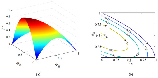
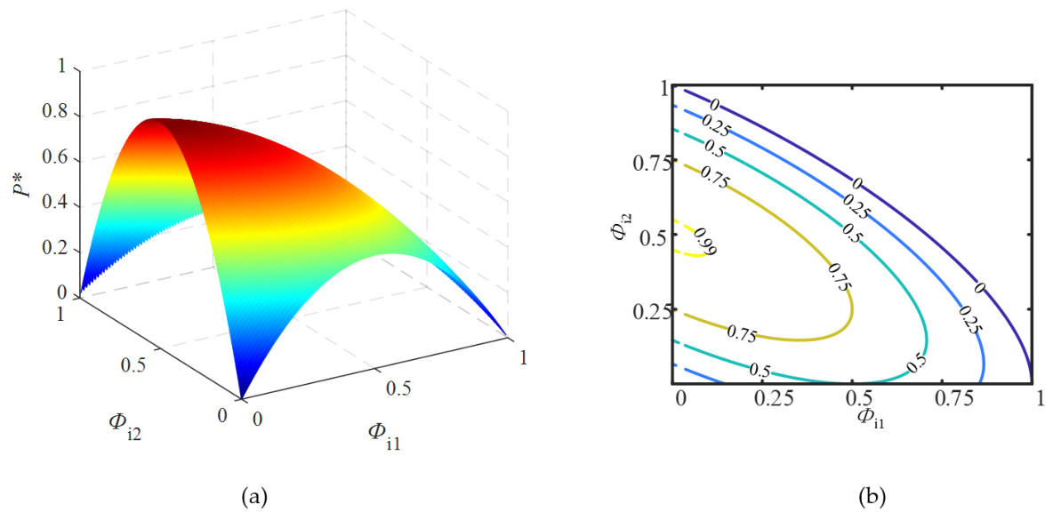
Based on Equation (12), the relationship between the normalized output power and the two phase-shift ratios is plotted in Figure 12a. Compared with the SPS control strategy, the additional phase-shift degree of freedom improves both the control flexibility and the power-regulation range of the converter. Moreover, the projected power-transfer characteristic shown in Figure 12b indicates that the HFB converter under the EPS control strategy can still achieve power transfer over the entire load range.
Figure 12.
Relationship curve between transferred power and phase-shift ratio under the EPS control strategy. (a) 3D plot of the relationship, (b) 2D projection of the relationship.
Power backflow is generally defined as the power transferred during the intervals in which either the half-bridge-side or full-bridge-side square-wave voltage has a polarity opposite to that of the inductor current. According to the operating waveforms shown in Figure 10a, the output-side backflow power of the HFB converter under the SPS control strategy can be expressed as follows:
where . Similarly, taking PB as the base value, the backflow power is normalized, and its per-unit value can be expressed as follows:
By combining Equations (10) and (14), the relationship between the per-unit full-bridge-side backflow power and the per-unit output power of the HFB converter under the SPS control strategy can be expressed as follows:
Similarly, based on the operating waveforms shown in Figure 10b, the per-unit output-side backflow power under the EPS control strategy can be expressed as follows:
Based on Equations (12) and (16), the relationship between the per-unit full-bridge-side backflow power and the per-unit output power under the EPS control strategy can be derived as follows:
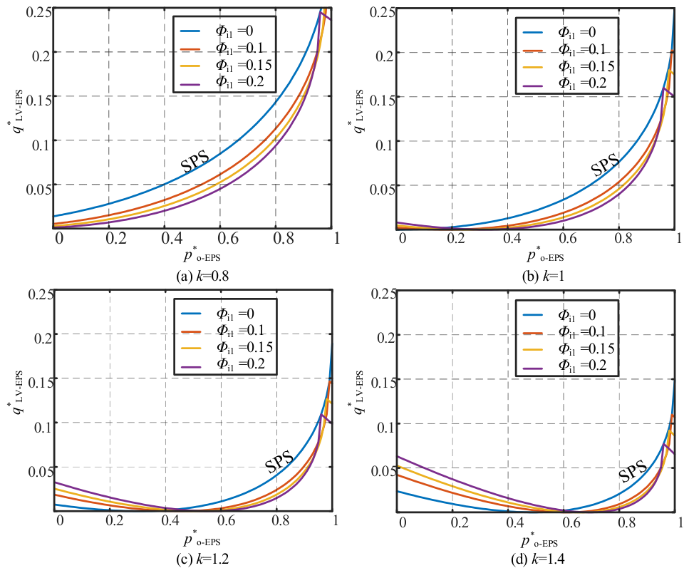
Equations (14)–(17) give theoretical per-unit backflow power for SPS and EPS strategies, and Figure 13 presents theoretical comparison curves. Due to limited revision time, experimental measurement of RMS current and device loss will be completed in future work.
Figure 13.
Relationship curve between transferred power and phase-shift ratio under the EPS control.
To compare the full-bridge-side backflow power of the HFB converter under the two control strategies, the relationships between the per-unit full-bridge-side backflow power and the per-unit transferred power are plotted in Figure 13 based on Equations (15) and (17). It can be observed that, under the EPS control strategy, the full-bridge-side backflow power can be reduced by introducing the inner phase-shift ratio Φi1 according to the required output power, thereby improving the operating efficiency of the converter. Figure 13b shows the full-bridge-side backflow-power characteristics under different control strategies when the voltage ratio is equal to 1. When the inner phase-shift ratio Φi1 is 0, the backflow power increases monotonically with the output power. By combining Equations (12) and (17) with the allowable ranges of Φi1 and Φi2, the two phase-shift ratios corresponding to the minimum backflow power can be expressed as follows:
Therefore, for a given voltage ratio and per-unit output power, the corresponding inner and outer phase-shift angles can be selected according to Equation (18) to suppress power backflow.
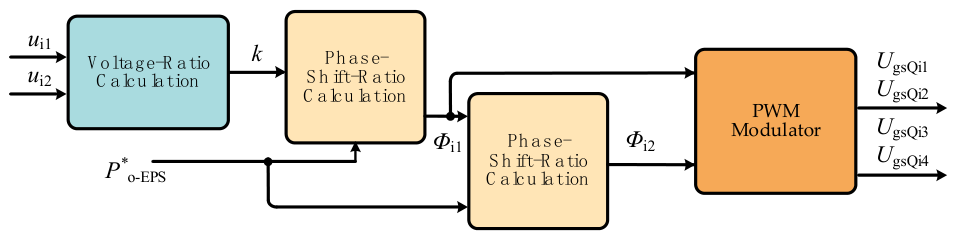
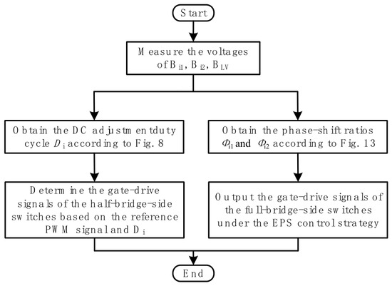
Figure 14 shows the control flowchart of the HFB converter under the EPS control strategy. Based on the voltage ratio and the specified per-unit output power, the inner and outer phase-shift ratios are calculated using Equation (18), thereby implementing EPS control. Figure 15 shows the overall control flowchart of the modular HFB converter. Each converter module can achieve voltage equalization between the battery cells within its half-bridge using the asymmetric modulation strategy shown in Figure 9, while EPS control can be independently implemented for each module according to the control scheme shown in Figure 14. The quantitative comparison of equalization speed and efficiency between SPS and the proposed EPS combined asymmetric modulation strategy will be presented in Section 4, Figure 21.
Figure 14.
Flowchart of the EPS control strategy.
Figure 15.
Overall control block diagram of the modular HFB converter.
Figure 15 illustrates control logic under normal operation. Once over-current fault is detected by hardware and software, all driving pulses will be immediately blocked for system protection.
4. Experimental Validation
To verify the equalization performance of the modular HFB converter and the feasibility of its auxiliary power module function, a simulation model consisting of two HFB converter modules was established in Simulink using the parameters listed in Table 1. To reduce the simulation time without affecting the circuit characteristics, each battery cell was equivalently represented by a 3-F capacitor. The initial voltages of the individual battery cells are listed in Table 2.
Table 1.
Parameter table for experiment and simulation.
Table 2.
Voltage conditions of individual battery cells in the modular HFB converter.
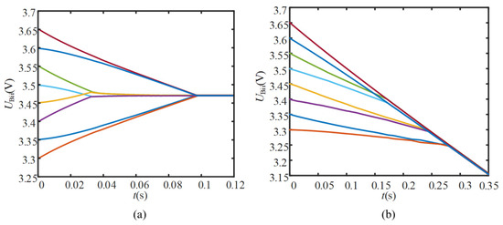
Figure 16a shows the voltage variations in the individual battery cells when the modular HFB converter operates in the C2C-only mode. It can be observed that the battery cells within the same half-bridge are equalized through the half-bridge circuit. For inter-group equalization between battery-cell groups connected to different half-bridges, the storage battery on the low-voltage side serves as an intermediate energy buffer. The converter module connected to the higher-voltage battery group operates with a positive phase-shift ratio, whereas the module connected to the lower-voltage battery group operates with a negative phase-shift ratio, thereby achieving inter-group voltage equalization. When the modular HFB converter is required to perform voltage equalization and the auxiliary power module function simultaneously, the C2C-and-H2L operating mode can be selected. The corresponding cell-voltage variations are shown in Figure 16b. Each HFB converter module transfers energy to the low-voltage side using a positive phase-shift ratio. Meanwhile, the converter module connected to the higher-voltage battery group adopts a larger phase-shift ratio and therefore releases more energy over the same operating interval. In this manner, voltage equalization is achieved while energy is transferred from the high-voltage side to the low-voltage side.
Figure 16.
Simulation curves of battery-cell voltage variations under different operating modes. (a) C2C-only operating mode, (b) C2C and H2L operating mode.
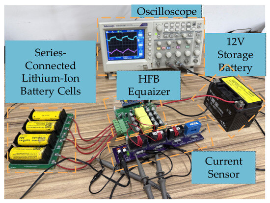
To verify the effectiveness of the asymmetric modulation strategy and the EPS control strategy, an experimental platform with four series-connected lithium-ion battery cells was constructed, as shown in Figure 17. The platform mainly consists of an HFB converter prototype, an oscilloscope, the series-connected lithium-ion battery cells, current sensors, a microcontroller-based control unit, and a 12 V storage battery. The detailed experimental parameters are listed in Table 1.
Figure 17.
Experimental prototype.
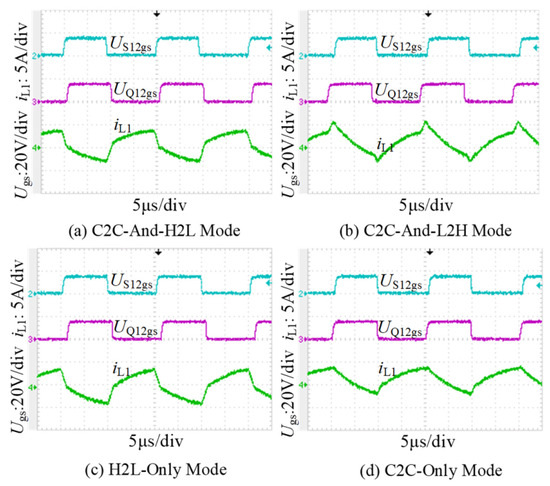
The investigated HFB converter can operate in four different modes by adjusting the phase-shift ratio. Figure 18 shows the switch gate signals and auxiliary-inductor current waveforms under the different operating modes. The initial voltages of the adjacent battery cells are listed in Table 1. Figure 18a shows the experimental waveforms in the C2C-and-H2L operating mode. In this mode, voltage equalization is performed between adjacent battery cells while energy is simultaneously transferred to the low-voltage side through a positive phase-shift ratio. As shown in Figure 18b, when the phase-shift ratio is negative, reverse power transfer from the low-voltage side to the high-voltage side can be achieved. The operating waveforms of the converter in the C2C-only mode are shown in Figure 18d. In this mode, no phase difference exists between the half-bridge-side and full-bridge-side voltages. When the gate signal of switch S11 is high, the higher-voltage battery cell B11 transfers energy to the auxiliary inductor and the transformer primary winding, causing the inductor current to increase. When S11 is turned off and the gate signal of S12 becomes high, the previously stored energy is transferred to battery cell B12, thereby achieving voltage equalization between the adjacent battery cells.
Figure 18.
Waveforms of US12gs, UQ12gs, and iL1 under different operating modes.
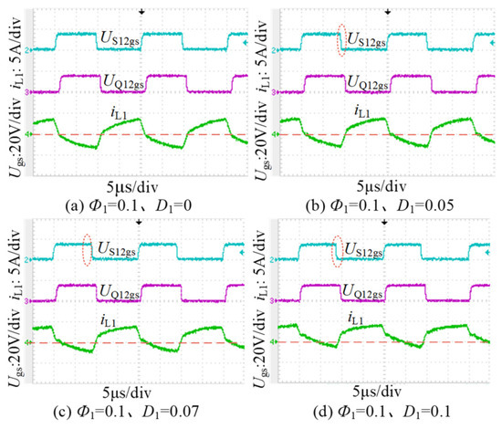
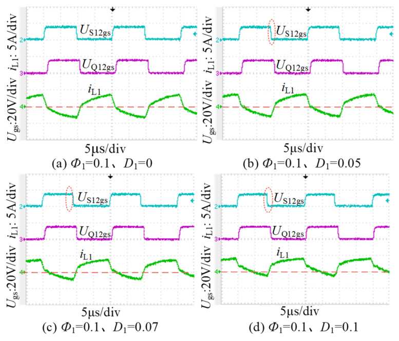
Taking initial-voltage condition 1 in Table 1 as an example, when the voltage difference between adjacent battery cells is 0.05 V, Figure 19 shows the waveforms of US12gs, UQ12gs, and iL1 under different DC adjustment duty cycles. As shown in Figure 19a, under the conventional symmetrical modulation strategy, when the cell-voltage difference is small, the DC component of the inductor current iL1 is also relatively small, resulting in a low equalization rate. As shown in Figure 19b–d, under the asymmetric modulation strategy, the DC component can be increased by introducing the DC adjustment duty cycle Di, thereby increasing the equalization current when the cell-voltage difference is small.
Figure 19.
Waveforms of US12gs, UQ12gs, and iL1 under various DC regulation duty ratios.
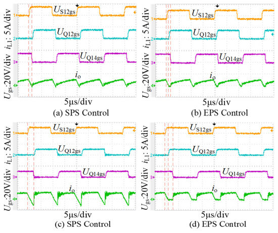
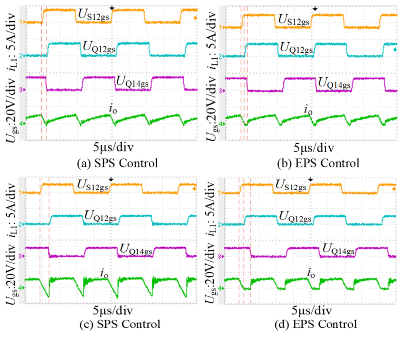
Figure 20 shows the experimental waveforms of the HFB converter under different control strategies when the per-unit output power is 0.5 and 0.8, respectively. The initial voltages of the two battery cells are both 3.6 V. As shown in Figure 20a,c, under the SPS control strategy, only one phase-shift ratio exists between switches S12 and Q12, resulting in a certain amount of backflow power on the full-bridge side. This phenomenon becomes more pronounced at higher output power.
Figure 20.
Main experimental waveforms of SPS and EPS control strategies under different output power levels.
The experimental waveforms under the EPS control strategy are shown in Figure 20b,d. In this case, in addition to the outer phase-shift ratio between the half-bridge and full-bridge sides, an inner phase-shift ratio Φ11 is introduced between switches Q12 and Q13. Consequently, no backflow power occurs on the full-bridge side during the interval defined by the inner phase shift. The experimental results demonstrate that the EPS-controlled HFB converter can effectively suppress full-bridge-side backflow power, thereby validating the theoretical analysis.
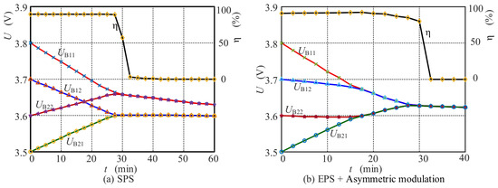
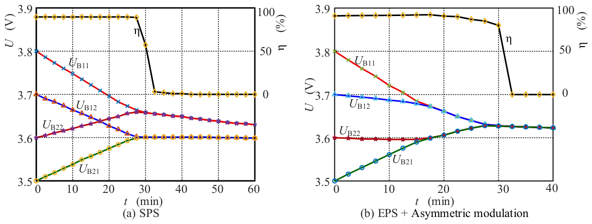
To further verify the effectiveness of the proposed asymmetric modulation plus EPS control strategy in this paper, the efficiency and equalization-voltage convergence curves of the APM converter prototype with its equalization function under the SPS control and EPS control are presented in Figure 21a and Figure 21b, respectively.
Figure 21.
Cell-voltage and efficiency curves under different control strategies.
It can be observed from Figure 21a that under the SPS control strategy, since the asymmetric modulation scheme is not adopted, the equalization between cells Bi1, Bi2(i = 1, 2) can only be realized through slow energy transfer driven by the voltage difference between the two cells, which results in a slow-voltage convergence between Bi1, Bi2. Under the SPS control, the cell equalization among HFB modules is basically completed at 30 min. Nevertheless, the convergence speed of the two cells within each HFB module becomes extremely slow after 30 min, which motivates the introduction of the asymmetric control in this work. The maximum equalization efficiency of the APM under the SPS strategy reaches 89.6%. However, the equalization efficiency drops sharply after the inter-module equalization is finished (after 30 min). When only intra-module cell equalization is performed, the efficiency is approximately zero.
It should be noted that the total power of equalizer Ptotal is equal to the releasing power of cells Pr or the sum of the absorbing power of cells Pa and the power loss Pl, that is, Ptotal = Pr = Pa + Pl. For example, cells B11 and B12 release power, and cells B21 and B22 absorb power. Then, Pa = PB11 + PB12 and Pr = PB21 + PB22. So, the efficiency is equal to (Pa/Pr) × 100%.
With the adoption of the EPS combined with asymmetric modulation strategy, the cell-voltage convergence curve and efficiency curve are depicted in Figure 21b. Compared with the SPS control strategy, two distinct improvements can be observed. First, the equalization of intra-module cells Bi1, Bi2(i = 1,2) is accomplished rapidly within approximately 16 min, while inter-module cell equalization is finished at around 28 min, leading to an overall improvement in equalization speed. Second, the circulating power is reduced under the EPS strategy, which contributes to a higher peak efficiency of 93.2%. It can be concluded that both the equalization speed and equalization efficiency are significantly enhanced by employing the proposed control strategy in this work.
When open-circuit fault occurs for one battery cell, all switching devices inside the corresponding faulty HFB module will be turned off. The remaining healthy modules can still deliver power to the low-voltage side to guarantee uninterrupted LV-load power supply. This paper mainly focuses on control-strategy research; a detailed fault-tolerant scheme will be explored in future work.
For practical EV battery packs with dozens or hundreds of series-connected cells, special battery monitoring chips, e.g., LTC6804-1, can be deployed. Each chip supports voltage measurement for 12 cells, and multiple chips can be daisy-chained. Sampling data is transmitted to the main MCU through an SPI bus. The microsecond-level communication delay of a daisy-chain SPI is far faster than battery-cell voltage variation, and its influence on equalization performance can be neglected.
Temperature tests for key components were implemented under a rated operating condition. At an ambient temperature of 25 °C, the steady-state temperature of the power switches reaches 38 °C, and the transformer core reaches 41 °C. Comprehensive thermal analysis under high-current equalization will be studied in future work.
5. Conclusions
To address the high cost of conventional active equalizers, this paper integrates lithium-ion battery active equalization into the auxiliary power module of an electric vehicle. An asymmetric modulation strategy is adopted to implement DC adjustment, enabling a relatively large equalization current to be maintained even when the voltage difference between battery cells is small. To reduce the output-side backflow power of the converter, an extended phase-shift control strategy is applied to the full-bridge side. By introducing an additional phase-shift degree of freedom, the backflow power is suppressed and the circuit losses are reduced. Simulation results demonstrate that the modular HFB converter can simultaneously perform battery equalization and auxiliary power conversion. Experimental results validate the proposed control strategies and confirm the effectiveness of the four operating modes.
Author Contributions
Conceptualization, N.C. and Y.W.; methodology, N.C. and Y.W.; software, N.C.; validation, N.C. and Y.W.; formal analysis, N.C. and Y.W.; investigation, N.C. and Y.Q.; resources, Y.W. and S.P.; data curation, N.C.; writing—original draft preparation, N.C.; writing—review and editing, N.C., S.P. and Y.Q.; visualization, N.C. and Y.Q.; supervision, Y.W. and S.P.; project administration, Y.W. and S.P.; funding acquisition, Y.W. and S.P. All authors have read and agreed to the published version of the manuscript.
Funding
This work was supported by the National Natural Science Foundation of China under Grant 52477226. The authors are with the Yancheng Institute of Technology, Yancheng, 224051, China. (email: kanxinlei@163.com).
Data Availability Statement
The data of this article cannot be made public.
Conflicts of Interest
The authors declare no conflicts of interest.
References
- Izadi, Y.; Beiranvand, R. A Comprehensive Review of Battery and Supercapacitor Cells Voltage-Equalizer Circuits. IEEE Trans. Power Electron. 2023, 38, 15671–15692. [Google Scholar] [CrossRef] [Scilit]
- Gholizadeh, M.; Salmasi, F.R. Unknown Nonlinearities, and State of Health of a Lithium-Ion Battery Based on a Comprehensive Unobservable Model. IEEE Trans. Ind. Electron. 2014, 61, 1335–1344. [Google Scholar] [CrossRef] [Scilit]
- Huang, Y.; Sun, X.; Hao, T.; Lu, B.; Chen, H. Whole Process Covert Attacks for Lithium-Ion Batteries in Battery Energy Storage Systems. IEEE Trans. Ind. Electron. 2026, 73, 6111–6122. [Google Scholar] [CrossRef] [Scilit]
- Peng, F.; Wang, H.; Yu, L. Analysis and Design Considerations of Efficiency Enhanced Hierarchical Battery Equalizer Based on Bipolar CCM Buck–Boost Units. IEEE Trans. Ind. Appl. 2019, 55, 4053–4063. [Google Scholar] [CrossRef] [Scilit]
- Chen, W.; Ding, Z.; Liu, J.; Kan, J.; Nazir, M.S.; Wang, Y. Half-Bridge Lithium-Ion Battery Equalizer Based on Phase-Shift Strategy. Sustainability 2023, 15, 1349. [Google Scholar] [CrossRef] [Scilit]
- Liu, W.; Song, Y.; Liao, H.; Li, H.; Zhang, X.; Jiao, Y.; Peng, J.; Huang, Z. Distributed Voltage Equalization Design for Supercapacitors Using State Observer. IEEE Trans. Ind. Appl. 2019, 55, 620–630. [Google Scholar] [CrossRef] [Scilit]
- Uno, M.; Kukita, A. String-to-Battery Voltage Equalizer Based on a Half-Bridge Converter with Multistacked Current Doublers for Series-Connected Batteries. IEEE Trans. Power Electron. 2019, 34, 1286–1298. [Google Scholar] [CrossRef] [Scilit]
- La, P.-H.; Choi, S.-J. Direct Cell-to-Cell Equalizer for Series Battery String Using Switch-Matrix Single-Capacitor Equalizer and Optimal Pairing Algorithm. IEEE Trans. Power Electron. 2022, 37, 8625–8639. [Google Scholar] [CrossRef] [Scilit]
- Shang, Y.; Xia, B.; Yang, J.; Zhang, C.; Cui, N.; Mi, C. A Delta-Structured Switched-Capacitor Equalizer for Series-Connected Battery Strings. In Proceedings of the 2017 IEEE Energy Conversion Congress and Exposition (ECCE), Cincinnati, OH, USA, 1–5 October 2017; IEEE: Piscataway, NJ, USA, 2017; Volume 1. [Google Scholar] [CrossRef] [Scilit]
- Shang, Y.; Cui, N.; Duan, B.; Zhang, C. Analysis and Optimization of Star-Structured Switched-Capacitor Equalizers for Series-Connected Battery Strings. IEEE Trans. Power Electron. 2018, 33, 9631–9646. [Google Scholar] [CrossRef] [Scilit]
- Li, G.; Liu, K.; Weng, W.; Wu, J.; Deng, Y.; He, X. Embedding Power Line Communication in Modular Battery Equalizers via AC Bus for Distributed Battery Management. IEEE Trans. Ind. Electron. 2026, 73, 5615–5626. [Google Scholar] [CrossRef] [Scilit]
- Chen, Y.; Liu, X.; Shen, T.; Cheng, L.; Wang, X.; Yang, R.; Yang, S. An any-cell(s)-to-cell(s) equalization method with a single magnetic component for Lithium-ion battery pack. J. Energy Storage 2021, 33, 102071. [Google Scholar] [CrossRef] [Scilit]
- Wang, S.; Wang, Y.; Chen, G.; Wei, D.; Shang, Y. An Efficient and Compact Equalizer Based on Forward-Flyback Conversion for Large-Scale Energy Storage Systems. IEEE Trans. Transp. Electrif. 2024, 10, 1222–1232. [Google Scholar] [CrossRef] [Scilit]
- Evzelman, M.; Rehman, M.U.; Hathaway, K.; Zane, R.; Costinett, D.; Maksimovic, D. Active Balancing System for Electric Vehicles with Incorporated Low-Voltage Bus. IEEE Trans. Power Electron. 2016, 31, 7887–7895. [Google Scholar] [CrossRef] [Scilit]
- Wang, W.; Preindl, M. Dual Cell Links for Battery-Balancing Auxiliary Power Modules: A Cost-Effective Increase of Accessible Pack Capacity. IEEE Trans. Ind. Appl. 2020, 56, 1752–1765. [Google Scholar] [CrossRef]
- Hou, N.; Song, W.; Wu, M. Minimum-Current-Stress Scheme of Dual Active Bridge DC–DC Converter With Unified Phase-Shift Control. IEEE Trans. Power Electron. 2016, 31, 8552–8561. [Google Scholar] [CrossRef] [Scilit]
- Zhao, B.; Yu, Q.; Sun, W. Extended-phase-shift control of isolated bidirectional DC-DC converter for power distribution in microgrid. IEEE Trans. Power Electron. 2012, 27, 4667–4680. [Google Scholar] [CrossRef] [Scilit]
- Guan, C.; Deng, Y.; Zhang, S.; Song, W.; Ma, C.; Zhang, Z. Digital-Twin Modeling and Parameter Monitoring Method of Dual Active Bridge DC–DC Converters with Improved Minimum Current Stress Optimization. IEEE Trans. Instrum. Meas. 2025, 74, 2554112. [Google Scholar] [CrossRef] [Scilit]
- Sha, J.; Liu, Z.; Zhang, Y. Disturbance Compensation-Based Discrete Single-Phase-Shift Control for DAB DC-DC Converter. IEEE Trans. Ind. Appl. 2025, 61, 3200–3208. [Google Scholar] [CrossRef] [Scilit]
- Guan, L.; Xiao, F.; Tu, C.; Lan, Z. Modal Analysis Method of DAB Based on Phase Shift Control. In Proceedings of the 2019 IEEE Energy Conversion Congress and Exposition (ECCE), Baltimore, MD, USA, 29 September–3 October 2019; IEEE: Piscataway, NJ, USA, 2019; pp. 5954–5959. [Google Scholar] [CrossRef] [Scilit]

Disclaimer/Publisher’s Note: The statements, opinions and data contained in all publications are solely those of the individual author(s) and contributor(s) and not of MDPI and/or the editor(s). MDPI and/or the editor(s) disclaim responsibility for any injury to people or property resulting from any ideas, methods, instructions or products referred to in the content. |
© 2026 by the authors. Licensee MDPI, Basel, Switzerland. This article is an open access article distributed under the terms and conditions of the Creative Commons Attribution (CC BY) license.