


Abstract
This work presents a dual-core embedded architecture for inner–outer loop control of a brushed DC servomechanism based on a dsPIC33CH128MP202 digital signal controller. The secondary core executes the PWM-synchronized current loop at 20 kHz and computes online performance and timing statistics, while the main core handles the incremental encoder, host communication, and inter-core data exchange. Three control schemes are evaluated on the same plant over five runs: direct PWM, a floating-point proportional-integral (PI) current controller, and the same discrete PI law in Q15 fixed-point arithmetic. The maximum observed loop execution times were 9.17 µs, 31.74 µs, and 10.50 µs, respectively, within the 50 µs sampling period. Independent oscilloscope measurements produced 9.19, 30.45, and 10.50 µs. Q15 reduced the maximum execution time by 66.9% and increased the timing margin from 18.26 to 39.50 µs. The two PI implementations showed no observable difference in position response and nearly identical steady-state current-loop RMSE values. The measurements show that Q15 implementation recovers substantial current-loop timing margin without measurable degradation in closed-loop performance, while also confirming the expected reduction in computational cost of fixed-point arithmetic. Current-reference tests from ±0.25 to ±1.00 A and emulated additional inertias were added for both PI implementations to examine current-loop accuracy and load sensitivity.
1. Introduction
The inner current loop of a DC motor power amplifier determines the electromagnetic torque delivered to the external velocity or position loops. When a current loop makes the electrical dynamics sufficiently faster than the mechanical dynamics, the motor can be operated in torque mode, and the external controller can be designed using a reduced mechanical model. Torque/current mode is important in academia, since many robotic and mechanical models take torque as the control input, and in industry, where servo drives employ a fast inner current loop to provide predictable torque regulation and current limiting. For these reasons, the didactic platform from which this work derives exposes a native current loop that is directly tunable from MATLAB [1]. The scope of this work addresses the embedded implementation of the current loop, while its classroom application is documented separately.
Experimental platforms that expose the current reference, measured current, PWM command, and mechanical variables are useful for controller implementation and for studying the assumptions behind cascade-control models [1,2,3,4,5]. The platform preceding this work used a single-core dsPIC30F4012 to execute the current PI controller, PWM generation, quadrature encoder processing, and host communication [1].
Recent embedded motor-control systems increasingly separate time-critical control from communication, logging, and supervisory tasks. Multicore implementations have been used to separate data logging from motor control and to increase control-data acquisition throughput [6,7,8], while recent embedded motor-drive studies have also emphasized the execution-time requirements of high-rate current control [9,10]. Cascade and dual-loop control remain standard structures for electromechanical actuators [11,12,13]. These papers establish the value of task partitioning but do not directly quantify, on the same plant and processor partition, how much in-ISR timing margin is recovered when only the numerical representation of an otherwise equivalent inner-loop controller is changed, nor whether that recovered margin is accompanied by an observable change in current-loop accuracy or external cascade dynamics.
In this paper we address that specific implementation-level question using a dual-core digital signal controller. The secondary core executes the 20 kHz current loop and statistics, while the main core handles encoder acquisition, sequencing and communication with the host. Direct PWM, floating-point PI, and Q15 fixed-point PI are compared under the same cascade control with an outer Proportional Derivative (PD) control loop. Integer arithmetic is expected to be faster than software floating point on a processor without a floating-point unit [14,15]. The contribution to this work is not that qualitative observation. Instead, the experiment quantifies the effect on the executed current-loop ISR body, including sample handling, controller evaluation, PWM update, and metric-handling overhead, and checks whether the recovered timing margin is accompanied by an observable change in current-loop error or external position response. The comparison is thus device-specific and is not intended as a general argument against floating-point-unit (FPU)-equipped motor-control devices; the selected dsPIC33CH128MP202 platform also reflects the practical objective of maintaining a low-cost design compatible with in-house fabrication on a double-sided PCB.
The contributions of this work are: (i) a reproducible dual-core partition in which the high-rate ADC-control-PWM path and online metrics are isolated on the secondary core; (ii) a same-hardware, same-plant comparison of equivalent floating-point and Q15 PI implementations in which the numerical representation is the principal implementation variable; (iii) execution-time characterization of the executed current-loop ISR body rather than the PI computation alone, complemented by an independent oscilloscope check; and (iv) an experimental assessment across five counterbalanced runs of whether the recovered timing margin is accompanied by an observable control-performance penalty. The term maximum observed execution time is used throughout the paper because the measurements are experimental and do not constitute an analytical worst-case execution-time (WCET) bound, particularly since the implementation does not employ a dedicated embedded real-time operating system (RTOS) kernel that would support formal WCET analysis.
The remainder of the paper is organized to reflect these contributions. Section 2 describes the dual-core partition, the equivalent floating-point and Q15 PI implementations, the executed current-loop ISR body, and the experimental protocol. Section 3 quantifies the recovered timing margin and evaluates whether it is accompanied by changes in current-loop accuracy or external position response. Section 4 discusses the practical implications and limitations of these results, and Section 5 summarizes the main findings.
2. Materials and Methods
2.1. Experimental Platform and Dual-Core Partition
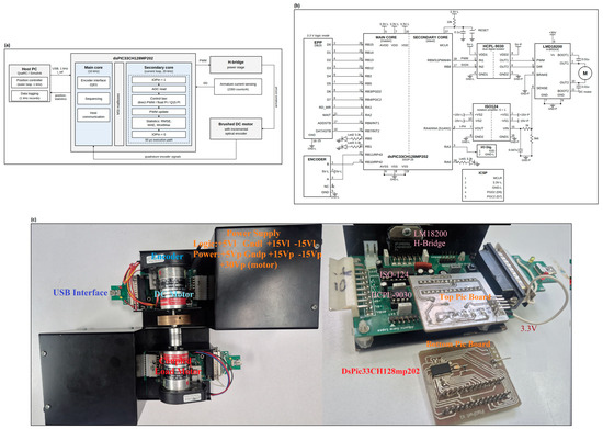
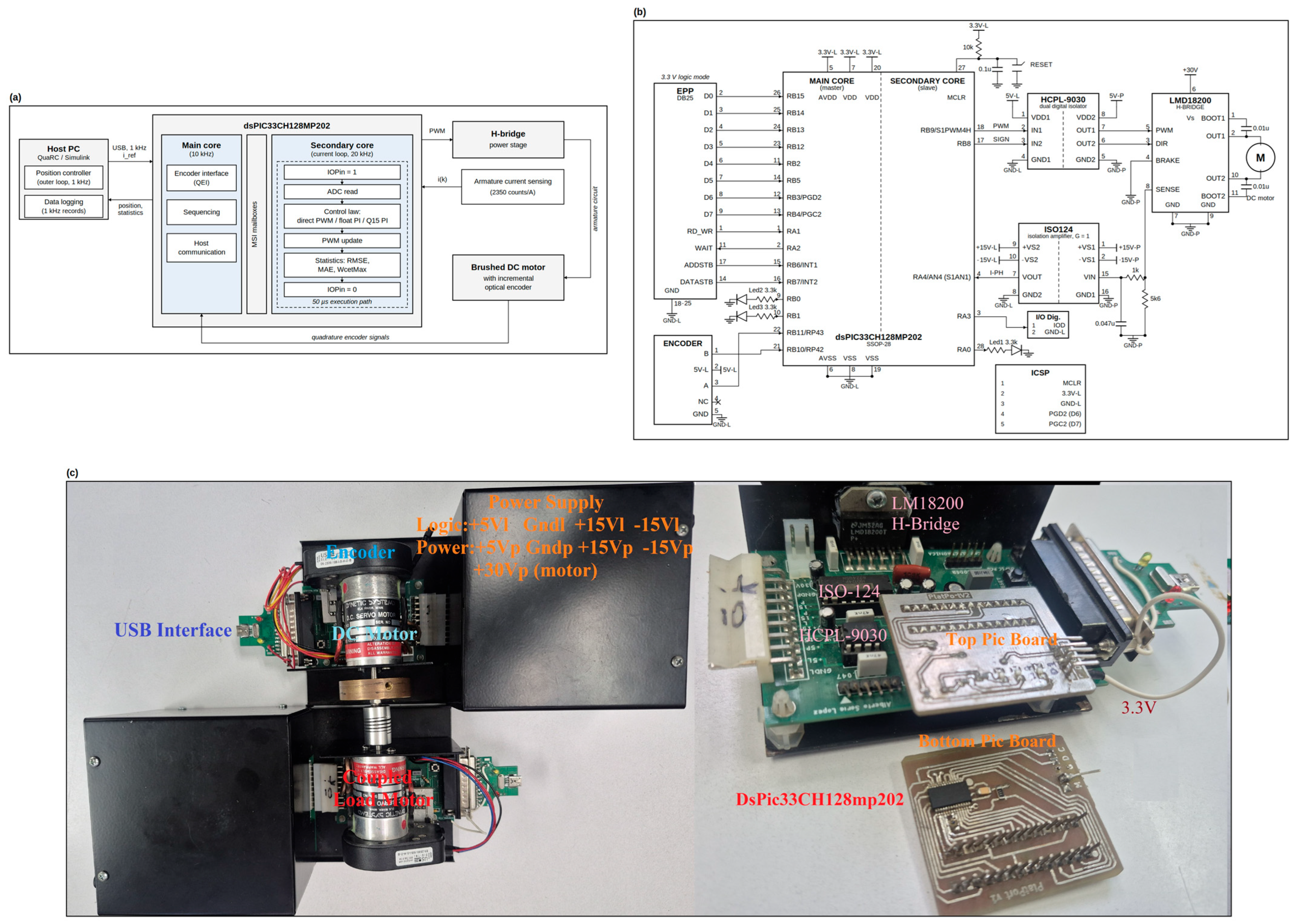
The experimental plant is a brushed DC servomechanism derived from the control platform reported in [1]. The power stage uses an LMD18200 H-bridge (Texas Instruments, Dallas, TX, USA) driving a Dynetic Systems DM-644 permanent-magnet brushed DC motor (Dynetic Systems, Elk River, MN, USA), with a US Digital E6 incremental optical encoder (US Digital, Vancouver, WA, USA) of 2500 pulses per revolution that allows 10,000 counts per revolution in quadrature read for shaft position. The motor is rated at 30 V and 1.3 A, with an armature resistance of 4.7 Ω, an armature inductance of 2.6 mH, a torque constant of 33.4 mN·m/A, and a no-load speed of 8000 rpm. The LMD18200 current-sense output is converted to voltage with the 5.6 kΩ resistor and transferred across the galvanic isolation barrier through an ISO124 isolation amplifier (Texas Instruments, Dallas, TX, USA). A 1 kΩ series resistor and 47 nF shunt capacitor are also present in the sensing path. For this current-source sensing topology, the capacitor sees the 5.6 kΩ current-sense resistor together with the 1 kΩ series resistor, giving an effective resistance of 6.6 kΩ and a first-order cutoff frequency of approximately 513 Hz. The LMD18200 is operated using sign and magnitude, with PWM setting the magnitude and the SIGN/DIR input setting the current direction. In this implementation the original single-core controller is replaced by a dsPIC33CH128MP202 dual-core digital signal controller (Microchip Technology, Chandler, AZ, USA). The high-rate tasks are performed by the secondary core; the main core is used for communication, synchronization and encoding, as well as speed updating. Figure 1 presents the experimental platform in three views: the functional architecture (a), the control-board schematic with the principal signal and pin assignments (b), and the assembled hardware with the mechanically coupled servomotors (c).
Figure 1.
The experimental platform in three views: (a) functional architecture, (b) system schematic, (c) assembled hardware. The dsPIC33CH128MP202 runs the 20 kHz current loop on its secondary core, and the logic and power stages are galvanically isolated.
The secondary core executes the current-loop ISR body at 20 kHz: pin RA3 = 1 for oscilloscope signal, acquisition of the current sample, selection of the control method, execution of the selected control method, PWM update, accumulation of online statistics and pin RA3 = 0. The main core reads encoder position, receives control parameters and references from the host, and transfers commands and statistics through the Main-Secondary Interface (MSI). This partition prevents host-side communication that is interrupt-driven and encoder-processing activities from being placed in the 50 µs current-loop execution path. The separation tasks between cores are treated here as the experimental context; a single-core versus dual-core timing comparison is not performed since strict current loop was not implemented in the single-core platform [1].
2.2. Cascade-Control Structure
The current controller constitutes the inner loop of a cascade architecture. The external position controller runs on the host using QuaRC 3.6 and MATLAB/Simulink R2012b at 1 kHz and generates the current reference/PWM transmitted to the embedded system. The position controller is a PD with proportional gain 36 and derivative gain 1.69, acting on the position error in turns to produce the current reference in amperes. The current reference is limited to ±1 A, below the 1.3 A motor rating, to favor a long motor life in continuous laboratory use. The current loop remains at 20 kHz for all tested conditions. The position reference alternates between −0.25 and +0.25 turns every second. Proper tuning of the inner loop gains makes the electrical pole dynamics fast relative to the mechanical pole, so that the external controller acts on a plant whose dominant behavior is mechanical, consistent with the modeling rationale of the preceding platform [1].
Three embedded control modes are considered. In direct-PWM mode, the host command is applied as a PWM command, and no current-tracking error is defined. In this mode the armature current cannot be limited by current feedback because no inner current controller acts on the applied command. Direct PWM is included primarily as an execution-time baseline for the acquisition, PWM-update, and statistics overhead common to all three modes, rather than as an equivalent closed-loop competitor to the two PI implementations. In floating-point PI mode, the current reference is regulated by a PI controller using single-precision floating-point arithmetic. In Q15 PI mode, the same discrete controller and gains are evaluated using integer fixed-point arithmetic.
2.3. Floating-Point and Q15 PI Implementations
For both PI implementations, the current error is
and the control output is computed with proportional action and a discrete integral state v[k] with output limiting as:
where u[k] is the PWM command applied to the power stage. The floating-point implementation uses Kp = 0.01 and the discrete integral coefficient KiTs = 0.8925 for the 50 µs sampling period. These coefficients are loaded from the parameter mailbox before the corresponding experimental segment and are not recomputed inside each 20 kHz current-loop execution. The maximum integral contribution was limited to 5100 PWM counts. Here e[k] is represented in ADC counts and u[k] and v[k] in PWM counts, so Kp and KiTs are expressed in PWM-count/ADC-count. The candidate integral state is clamped to the configured integral limit; conditional integration prevents further accumulation when the PWM output is saturated in the same direction as the current error, and the integral state is reset when the requested current direction reverses. In this magnitude-based current-control law, i[k] denotes the measured current magnitude; the current-reference sign is applied to the PWM command as shown in (2). The accepted integral state v[k] equals the clamped candidate when conditional integration is permitted; otherwise, it retains its previous value.
For the Q15 implementation, the same nominal proportional coefficient Kp = 0.01 and discrete integral coefficient KiTs = 0.8925 are represented with 15 fractional bits. The firmware uses
and evaluates the control law using integer multiplication, rounding, and right shifts. With the coefficients used in the experiments, the stored Q15 values are Kp,Q15 = 328 and KiTs,Q15 = 29245. These correspond to coefficient errors of +0.098% and −0.0015%, respectively, relative to the floating-point values. The mailbox-to-Q15 conversion is implemented without division and is performed outside the 20 kHz current-loop path. Both PI implementations use the same current reference, saturation limits, integral-contribution limit, and controller structure; the intended experimental difference is the numerical representation and associated arithmetic. The discrete-time and embedded numerical implementation follow the standard digital-control and real-time implementation considerations discussed in [14,15]. In both implementations, the integral state is reset when the current-reference direction reverses, clamped to the configured integral limit, and conditionally updated so that integration is not increased when the PWM output is saturated and the current error requests additional output. In Q15, the products are accumulated in 32-bit integer arithmetic, rounded by adding 214 before the 15-bit right shift, and then saturated to the PWM limit; the current-reference sign is applied afterward.
2.4. Online Error Metrics and External Execution-Time Measurement
The secondary core accumulates current-loop statistics over windows of 20 samples. At 20 kHz, each statistics window represents 1 ms of current-loop operation. For the PI modes, the firmware accumulates the sum of squared errors and the integral absolute error. The host computes RMSE = sqrt (SumSqrErr/20) and MAE = IAE/20. These metrics are not interpreted for direct PWM because its input is a modulation command rather than a physical current reference.
The conversion factor of 2350 ADC counts per ampere was obtained with the rotor blocked by comparing the ADC reading with a multimeter connected in series with the motor. The same nominal scaling is used for the current-reference and measured-current channels. Because this is a single nominal conversion rather than a multipoint metrological calibration, count-domain RMSE and MAE are treated as the primary accuracy measures. Milliampere values are reported only as a scale conversion.
Execution time is measured internally with Timer1 operating as a free-running 16-bit counter at FCY = 100 MHz with a 1:1 prescaler, corresponding to 10 ns per count. At each current-loop execution, elapsed counts are obtained, and the maximum value within each 20-sample statistics window is retained. The timing result reported for each operating mode is the global maximum observed over all valid windows and five runs. An independent oscilloscope measurement was also performed to check the embedded result. Pin RA3, with ownership assigned to the secondary core, is set high by the first instruction of the ADC interrupt service routine and cleared by its last instruction. Therefore, both the Timer1 statistic and the RA3 pulse characterize the executed ISR body; ADC acquisition/conversion time and interrupt-entry latency preceding the first ISR instruction are outside this measured interval and were not separately characterized. The pulse width was measured at 50% of the pulse amplitude with a LeCroy WaveRunner 104MXi oscilloscope (Teledyne LeCroy, Chestnut Ridge, NY, USA), using its statistical width measurement accumulated over repeated acquisitions for each operating mode. The oscilloscope maxima were 9.19 µs for direct PWM, 30.45 µs for floating-point PI, and 10.50 µs for Q15 PI. These quantities are experimentally observed in-ISR execution times and are not presented as formal WCET bounds. The embedded timing measurements were obtained independently using Timer1 on the secondary core. Because the secondary-core firmware operates at FCY = 100 MHz, the Timer1 conversion corresponds to 10 ns per count.
2.5. Experimental Protocol and Data Analysis
Five independent experimental runs were performed. Each run lasted for 6s and contained 6001 host samples at 1 kHz. The three conditions occupied consecutive 2 s segments, but their order was counterbalanced across runs using the sequences 123, 321, 231, 132, and 312, where Method 1 denotes direct PWM, Method 2 the floating-point PI, and Method 3 the Q15 PI. This procedure avoids systematically assigning one method to the final segment, when motor temperature may be higher. A warm-up run was performed before data collection and discarded, and a rest interval was allowed between runs.
External position performance was evaluated from equivalent positive reference steps. Rise time was measured from 10% to 90% of the step amplitude, settling time measurement used a ±0.005-turn band around the final reference, and overshoot and steady-state error were also computed. For the inner loop, steady-state RMSE and MAE were summarized using the median and interquartile range from 0.30 to 0.90 s after each step. For timing, the maximum reported value is the global maximum of the embedded Timer1 statistic over all valid 1 ms windows and five runs; the oscilloscope measurement is used as an independent timing check.
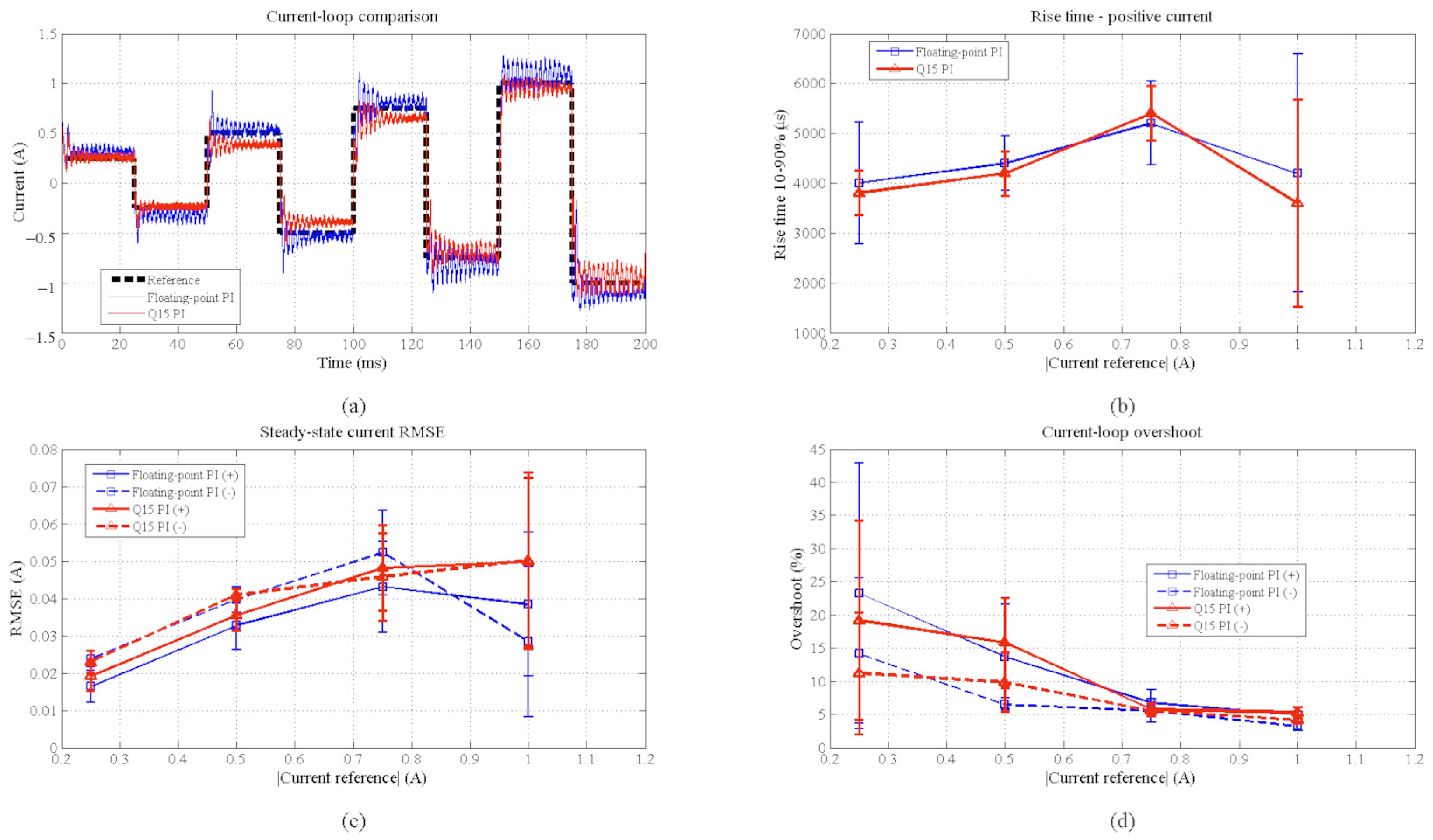
Inner-current-loop experiments were performed with the outer position loop bypassed and no emulated added inertia (nJ = 0). For each controller, five 200 ms runs applied eight consecutive 25 ms current-reference levels: +0.25, −0.25, +0.50, −0.50, +0.75, −0.75, +1.00, and −1.00 A. Rise time, overshoot, steady-state RMSE, standard deviation, and ripple were evaluated by reference magnitude and polarity. In addition, representative Method 2 and Method 3 current-sense signals were acquired directly at the ADC input with the WaveRunner oscilloscope at 1 MS/s and stored in matlab compatible file. The two oscilloscope records were independently time-aligned to the common 200 ms reference sequence, and the current sign was reconstructed from the programmed alternating positive and negative intervals. The repeated-run metrics shown in Figure 3b–d were computed from the 1 kHz host record (1 ms sample interval), whereas Figure 3a uses the independent 1 MS/s oscilloscope acquisition. Thus, panel (a) shows a representative fast electrical transient, while the repeated-run rise-time statistics retain the 1 ms host-sampling quantization.
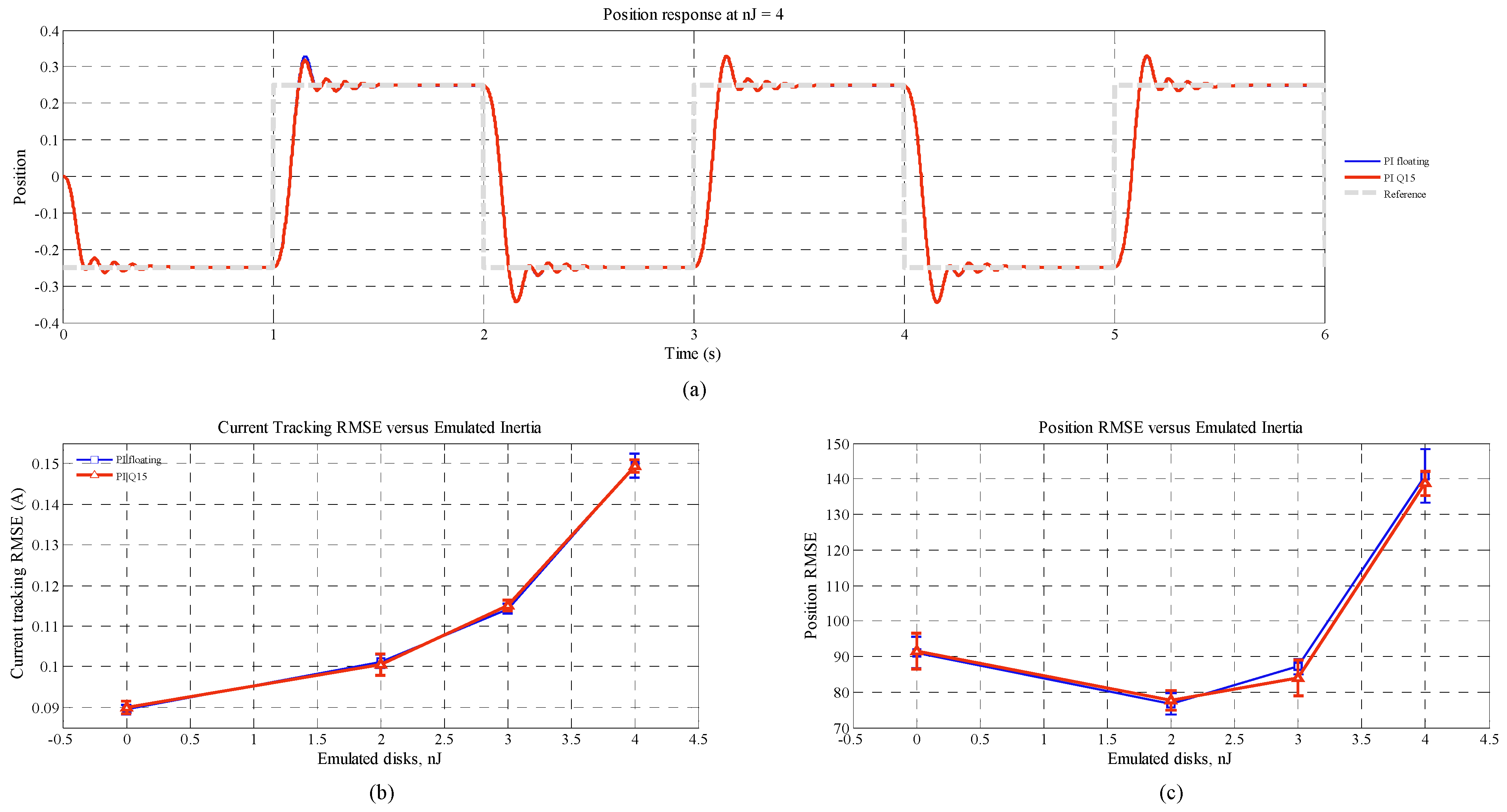
To examine sensitivity to mechanical loading, a second, mechanically coupled servo motor system identical to the drive motor was used as a programmable torque load. The measurement of a bronze disk (mass 0.200 kg, outer diameter 0.050 m, central-hole diameter 0.005 m) defines Jdisk = 6.3125 × 10⁻⁵ kg·m2. The load servo emulates Jadd = nJ·Jdisk from the drive-motor acceleration estimate, with load-current reference IL,ref = −nJ (Jdisk/Kt) and Kt = 0.0334 N·m/A. For each control method, including the floating-point PI and Q15 PI implementations, five repetitions were performed at nJ = 0, 2, 3, and 4 with the outer loop PD gains, reference trajectory, sampling periods, and mechanical coupling unchanged. The load motor employs Method 3 from the host-computed load-current reference. For the acceleration estimate, a Kalman estimator and two successive filtered-derivative stages, each of the form , with and , respectively, were first implemented and compared. Because the Kalman implementation did not provide a substantial noise reduction under the tested conditions, the simpler two-stage filtered-derivative estimator was used consistently in the added-inertia experiment.
Generative artificial intelligence was used to assist in developing portions of the embedded dsPIC code and for manuscript language editing. Figure 1 was integrated using generative artificial intelligence. All AI-assisted code was reviewed, tested, corrected, and integrated by the author. All AI-assisted text was revised carefully by the author, and no AI-generated text was used directly without author review and modification. GenAI was not used to generate experimental data or the scientific conclusions of the paper.
3. Results
3.1. External Position Response
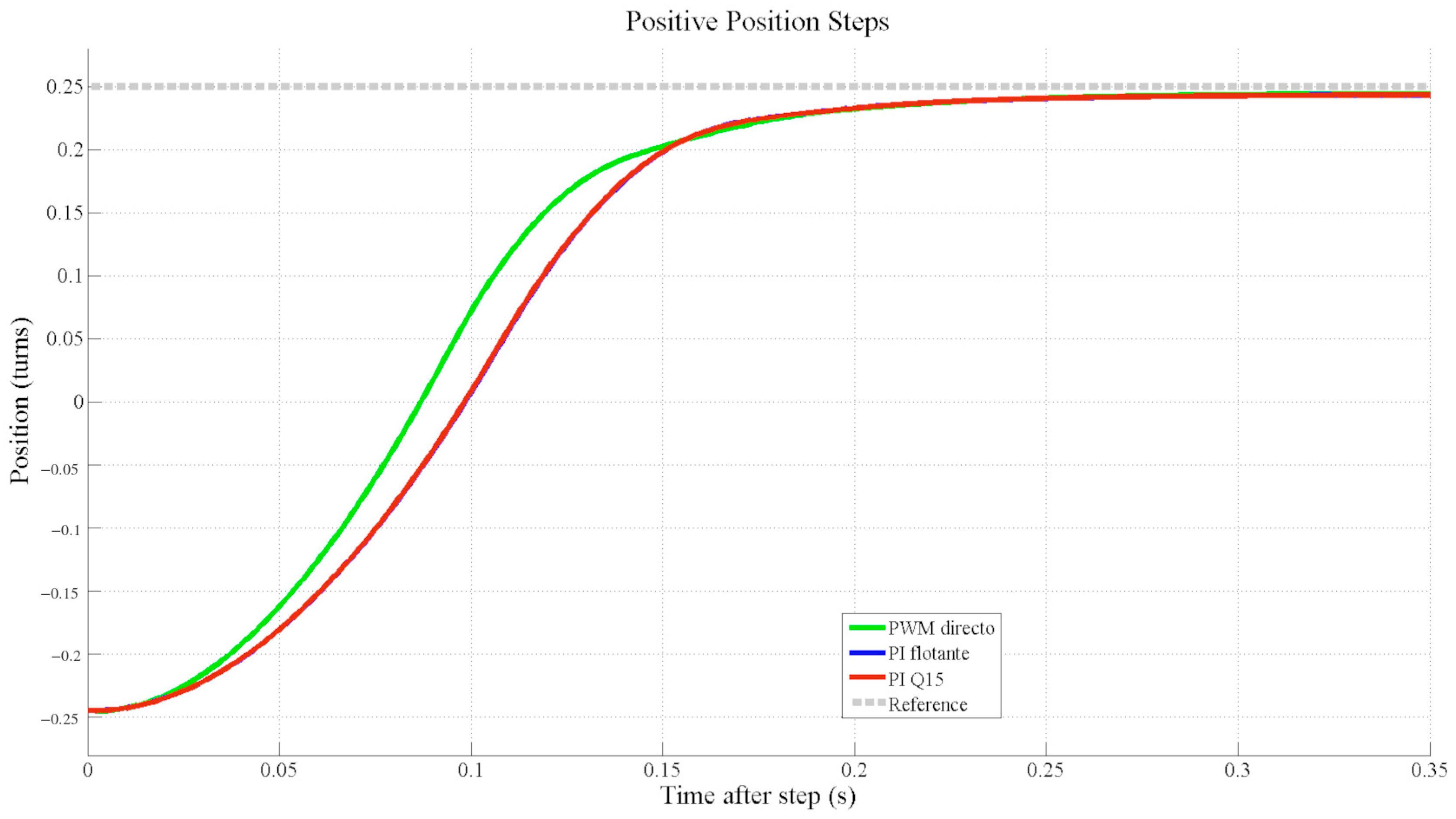
A representative 6 s record contains the three operating conditions. The reference alternates between −0.25 and +0.25 turns, and the external position response remains stable in all cases. The two PI implementations exhibit closely overlapping trajectories.
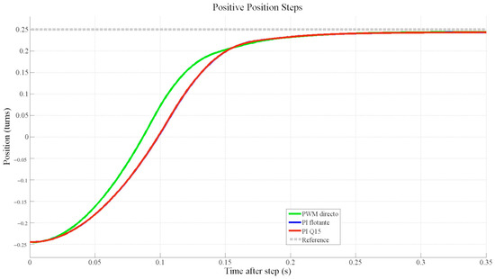
Figure 2 superimposes the mean equivalent positive-step responses for the three conditions across the five runs. No separation between the floating-point and Q15 responses is observable at the 1 ms host sampling interval. It should be noted that the PWM control is scaled directly to the full PWM range, allowing a larger current than the maximum reference used for the PI-controlled modes.
Figure 2.
Mean equivalent positive position steps for direct PWM, floating-point PI, and Q15 PI across five runs.
No overshoot was observed in any run, since the outer-loop proportional and derivative gains were tuned accordingly and remained fixed for all runs. The steady-state position error was −0.00190 ± 0.00019 turns for direct PWM, −0.00206 ± 0.00011 turns for the floating-point PI, and −0.00207 ± 0.00011 turns for the Q15 PI. The run-by-run paired Q15-minus-floating differences were 0.00 ± 0.00 ms for rise time and +0.20 ± 1.30 ms for settling time. The rise-time difference is below the 1 ms temporal resolution of the host record, and the settling-time difference is also smaller than that resolution in its mean value. The zero standard deviations for the 95.0 ms PI rise times reflect the 1 ms temporal quantization of the host record: all five runs yielded the same sampled crossing times for both PI implementations. For the settling-time paired difference, the corresponding 95% confidence interval is approximately −1.41 to +1.81 ms; the rise-time paired difference remains 0 ms at the 1 ms recording resolution. The corresponding external position-response indicators are summarized in Table 1.
Table 1.
External position-response indicators, mean ± standard deviation over five runs.
3.2. Current-Loop Accuracy
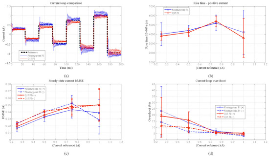
Figure 3 summarizes the dedicated inner-current-loop comparison of the floating-point and Q15 PI implementations. Panel (a) shows representative 1 MS/s oscilloscope current responses for the programmed reference sequence, while panels (b)–(d) summarize the repeated-run rise time, steady-state RMSE, and overshoot at |Iref| = 0.25, 0.50, 0.75, and 1.00A. Across the tested levels, both implementations exhibit closely similar current-loop behavior, with the largest dispersion occurring at the lower-current conditions. The corresponding steady-state current RMSE values by reference magnitude and polarity are reported in Table 2.
Figure 3.
Current-loop performance comparison for the floating-point and Q15 PI implementations. (a) Representative current responses acquired directly from the current-sensing signal at the ADC input using an oscilloscope at 1 MS/s; the two traces were independently time-aligned to the common reference sequence, and the current sign was reconstructed from the programmed alternating positive and negative reference intervals. (b) Positive-current 10–90% rise time. (c) Steady-state current RMSE for positive and negative references. (d) Current-loop overshoot for positive and negative references. Error bars indicate the standard deviation across repeated runs.
Table 2.
Steady-state current RMSE by current-reference magnitude and polarity, mean ± standard deviation over five runs.
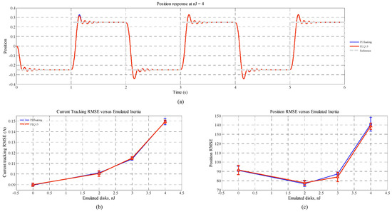
Figure 4 compares the floating-point and Q15 PI implementations under programmable added inertia. Panel (a) shows representative position responses at nJ = 4, while panels (b) and (c) report current-tracking RMSE and position RMSE for nJ = 0, 2, 3, and 4. Both implementations show closely overlapping trends as inertia increases; error bars indicate ±1 standard deviation over five runs.
Figure 4.
Floating-point versus Q15 PI performance under programmable added inertia. (a) Representative position responses at nJ = 4. (b) Current-tracking RMSE versus emulated inertia. (c) Position RMSE versus emulated inertia. The tested levels are nJ = 0, 2, 3, and 4, where one inertia unit corresponds to Jdisk = 6.3125 × 10⁻⁵ kg·m2. Error bars indicate ±1 standard deviation over five runs.
The original cascade experiment provides an additional accuracy check. Median RMSE was 26.99 counts for floating-point and 26.97 counts for Q15, corresponding to 11.49 and 11.48 mA. The corresponding median MAE values were 22.20 and 21.96 counts, or approximately 9.45 and 9.35 mA. The RMSE ranges were 13.15 and 12.42 counts, and the MAE ranges were 11.24 and 10.58 counts, respectively. Relative to floating-point, the count-domain RMSE changed by −0.1% and MAE by −1.1%. Within the resolution and calibration limits of the experiment, no current-loop accuracy penalty was detected for Q15, and no corresponding difference was observable in the external position response.
3.3. Observed Execution-Time Budget
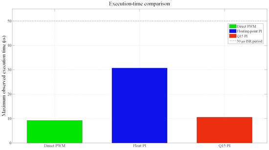
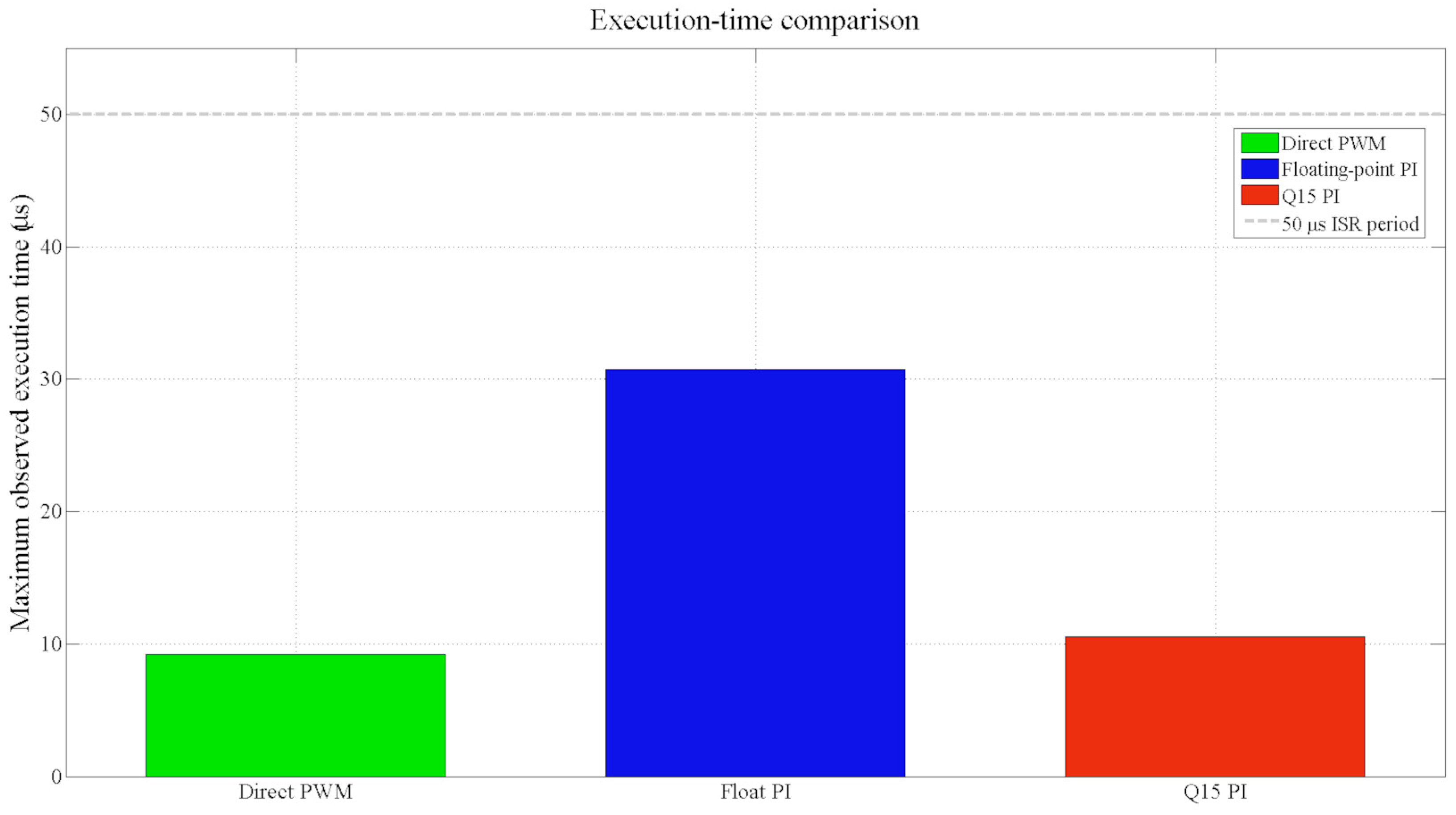
Figure 5 compares the global maximum observed embedded Timer1 execution time with the 50 µs period available at 20 kHz and overlays the independent oscilloscope maxima. The floating-point PI occupies a substantially larger fraction of the period than either direct PWM or Q15 PI, while the two measurement methods show the same timing hierarchy and closely corresponding absolute values.
Figure 5.
Maximum observed current-loop execution time relative to the 50 µs sampling period. Bars show the global embedded Timer1 maxima over five runs; markers show the independent oscilloscope maxima.
Changing from floating-point to Q15 reduced the embedded maximum observed loop execution time from 31.74 to 10.50 µs, corresponding to a 66.9% reduction. The available per-period margin increased from 18.26 to 39.50 µs. The independent oscilloscope maxima were 30.45 and 10.50 µs for floating-point and Q15 PI, respectively, corroborating the same timing hierarchy. The embedded and oscilloscope maxima were obtained from independent acquisition populations rather than from the same individual interrupt instances, so exact equality of the two maxima is not expected; the largest absolute difference, 1.29 µs for floating point, does not alter the timing conclusion. Using direct PWM as a baseline for the common acquisition, PWM-update, and statistics overhead, the additional observed cost associated with the PI computation was 22.57 µs for floating point and 1.33 µs for Q15. This baseline subtraction corresponds to a 17.0-fold difference and a 94.1% reduction in the isolated controller-related cost. At the system level, the 66.9% reduction remains the figure of interest because it represents the margin recovered in the measured current-loop ISR body. The corresponding embedded execution-time budget and Q15-versus-floating-point differences are summarized in Table 3.
Table 3.
Embedded execution-time budget over five runs. The maximum is the global maximum observed over all valid 1 ms statistics windows; the median summarizes the complete timing record.
4. Discussion
The central result of the experiment is a system-level timing comparison, not the general observation that fixed-point arithmetic can execute faster than software floating point. On the same plant, same dsPIC33CH secondary core, same 20 kHz sampling period, and same discrete PI structure, changing the numerical representation reduced the maximum observed occupancy of the measured current-loop ISR body from 63.5% to 21.0%. The recovered 21.24 µs of per-period margin includes the shared acquisition, PWM-update, and statistics overhead and is therefore more directly relevant to additional embedded functions than an isolated arithmetic benchmark. In engineering terms, this margin can be used for additional signal processing, diagnostics, more computationally demanding control functions, or to increase the current-loop sampling rate, thereby reducing digital control delay and potentially allowing a higher current-loop bandwidth, subject to the limits imposed by the sensing and power stages. The independent oscilloscope measurement reproduced the same timing hierarchy, with differences from the embedded Timer1 maxima of 0.02 µs for direct PWM, 0.00 µs for Q15 PI, and 1.29 µs for the floating-point PI.
This result is specific to the dsPIC33CH128MP202, which lacks a hardware FPU. FPU-equipped devices may reduce the timing advantage of fixed-point arithmetic over floating point. Using a 70% occupancy budget, the observed timing maxima correspond to scheduling ceilings of approximately 22.1 kHz for the floating-point PI and 66.7 kHz for Q15, although these are timing estimates rather than achievable control bandwidths. The motor electrical pole is approximately 288 Hz and the current-sensing pole about 513 Hz, while the measured 4–5 ms rise times indicate an effective closed-loop bandwidth of roughly 70–90 Hz. Future work could explore higher sensing bandwidths by shifting the sensing pole upward, accepting increased noise measurement and compensating it through Kalman-based or related estimation techniques. In this context, the additional Q15 timing margin provides useful computational headroom for more advanced estimation and control strategies.
The additional timing margin was obtained without an observable current-loop accuracy penalty in the tested runs. In the primary count-domain measures, median steady-state RMSE changed from 26.99 counts for floating point to 26.97 counts for Q15, while MAE changed from 22.20 to 21.96 counts. The external cascade response likewise showed no observable degradation at the 1 ms host-recording resolution: both PI implementations had the same sampled 95.0 ms rise time, and their mean settling times differed by only 0.20 ms. These results should be interpreted as absence of a detected difference within the resolution and calibration limits of this experiment, not as a formal proof of controller equivalence. For the tested operating condition, the numerical representation therefore changed computational cost much more strongly than the measured control response.
The experimental design also reduces two common sources of bias in embedded timing comparisons. First, all control methods were evaluated on the same hardware and plant, so differences are not confounded by processor, power-stage, or sensor changes. Second, the condition order was counterbalanced across runs, so no method was systematically tested last, when the motor is warmer. Direct PWM further provides an empirical baseline for the execution overhead shared by the three methods.
The present characterization has several limitations. Timer1 provides an embedded elapsed-time measurement, and the oscilloscope supplies an independent external check, but neither establishes a formal worst-case execution-time bound or characterizes interrupt-entry jitter and unexercised execution paths. Only five repetitions were used in each experiment; the dedicated current-step comparison was performed at nJ = 0, while the programmable-inertia experiments compared the floating-point and Q15 PI implementations over nJ = 0, 2, 3, and 4, so the control-performance comparison should not be interpreted as a formal equivalence result. In addition, the conversion from ADC counts to current uses a single nominal factor of 2350 counts/A; a multipoint calibration would improve the accuracy and uncertainty characterization of the reported milliampere values without affecting the primary count-domain comparison. Finally, the dual-core architecture is not benchmarked against the preceding single-core platform because comparable current-loop timing measurements were not available.
5. Conclusions
A dual-core dsPIC33CH128MP202 architecture was evaluated for a 20 kHz current loop in a cascade-controlled DC servomechanism. The secondary core executes current acquisition, PI control, PWM update, and online statistics, while the main core handles encoder processing, sequencing and host communication. The experiment was designed to quantify the in-ISR timing effect of changing the numerical representation of an otherwise equivalent PI implementation on the same plant and processor partition. Across five runs, replacing the floating-point PI with Q15 reduced the global maximum observed in-ISR execution time from 31.74 to 10.50 µs, increasing the available timing margin from 18.26 to 39.50 µs within the 50 µs period. Independent oscilloscope maxima of 30.45 and 10.50 µs for the two PI implementations corroborated the timing hierarchy.
The recovered timing margin was not accompanied by an observable degradation of the external position dynamics at the 1ms recording resolution. Both PI implementations yielded a rise time of 95.0 ± 0.0ms, while settling time changed only from 235.0 ± 1.9 to 235.2 ± 2.4ms. Their primary count-domain steady-state current errors were likewise essentially unchanged: median RMSE was 26.99 counts for the floating point and 26.97 counts for Q15. For the tested architecture and operating condition, fixed-point arithmetic recovered substantial margin in the measured embedded current-loop ISR body while preserving the observed current-loop accuracy and cascade response. These findings are experimental maximum-observed results rather than formal WCET. Further work will investigate whether a higher current-loop bandwidth can be obtained by increasing the current-sensing cutoff frequency. Because a faster analog filter also admits more measurement noise, the recovered computational margin will be used to evaluate EMA and Kalman filtering as alternatives for preserving noise attenuation while allowing a faster current-sensing path. A separate programmable-load experiment using the mechanically coupled second servomotor compared the floating-point and Q15 PI implementations over nJ = 0, 2, 3, and 4. Both implementations showed closely overlapping current-tracking and position-RMSE trends as the emulated inertia increased, providing a load-sensitivity check over the tested range rather than a universal load-invariance claim.
Funding
This research received no external funding.
Data Availability Statement
The experimental records and analysis scripts presented in this study are available at: https://drive.google.com/drive/folders/1kSjhMziNsqM5TIhO0W68_CiUFwRA32fM?usp=drive_link (accessed on 6 September 2026).
Conflicts of Interest
The author declares no conflicts of interest.
References
- González-Vargas, A.M.; Serna-Ramirez, J.M.; Fory-Aguirre, C.; Ojeda-Misses, A.; Cardona-Ordoñez, J.M.; Tombé-Andrade, J.; Soria-López, A. A Low-Cost, Free-Software Platform with Hard Real-Time Performance for Control Engineering Education. Comput. Appl. Eng. Educ. 2019, 27, 406–418. [Google Scholar] [CrossRef] [Scilit]
- Chen, X.M.; Gong, X.L.; Zhou, H.X.; Xu, Z.B.; Xu, Y.G.; Kang, C.J. An Economical Rapid Control Prototyping System Design with MATLAB/Simulink and TMS320F2812 DSP. In Proceedings of the International MultiConference of Engineers and Computer Scientists, Hong Kong, China, 17–19 March 2010; Volume II, pp. 951–956. [Google Scholar]
- Porobić, V.; Adžić, E.; Vekić, M.; Grabić, S.; Ivanović, Z. Educational Framework for a Motor Drive Control Systems: Design and Performance Assessment. Comput. Appl. Eng. Educ. 2017, 25, 264–276. [Google Scholar] [CrossRef] [Scilit]
- Uyanik, I.; Catalbas, B. A Low-Cost Feedback Control Systems Laboratory Setup via Arduino-Simulink Interface. Comput. Appl. Eng. Educ. 2018, 26, 718–726. [Google Scholar] [CrossRef] [Scilit]
- Kuczmann, M. Review of DC Motor Modeling and Linear Control: Theory with Laboratory Tests. Electronics 2024, 13, 2225. [Google Scholar] [CrossRef] [Scilit]
- Tran, D.M.; Choi, J.-Y. Distributed Data Logger Based on Dual-Core MCU in Motor Drive. In Proceedings of the 2023 IEEE 16th International Symposium on Embedded Multicore/Many-core Systems-on-Chip (MCSoC), Singapore, 18–21 December 2023; pp. 406–410. [Google Scholar] [CrossRef] [Scilit]
- Tran, D.M.; Choi, J.-Y. A Real-Time Data Storage Method for AC Servo Motor Drives Using Micro SD Card. IEEE Access 2023, 11, 121470–121481. [Google Scholar] [CrossRef] [Scilit]
- Lee, S.-H.; Tran, D.M.; Choi, J.-Y. High-Throughput Control-Data Acquisition for Multicore MCU-Based Real-Time Control Systems Using Double Buffering over Ethernet. Electronics 2026, 15, 469. [Google Scholar] [CrossRef] [Scilit]
- De Boni, G.; Mantione, L.; Frosini, L. Embedded Implementation and Characterization of a Model Predictive Control in Velocity Form for Synchronous Motor Currents. Electronics 2026, 15, 2561. [Google Scholar] [CrossRef] [Scilit]
- Sheng, J.; Liu, L.; Ding, Z.; Wu, J. Achieving 2.5µs Current Loop for PMSM Control via a High-Performance Dual-Core Framework on a Low-Cost MCU. TechRxiv 2025. [Google Scholar] [CrossRef] [Scilit] [PubMed]
- Abdullah Eissa, M.; Zeng, Z.; Darwish, R.R. Resolving the Adaptation–Robustness Trade-Off: A Dual-Loop Optimal Feedback Control Architecture for BLDC Drives. Actuators 2026, 15, 70. [Google Scholar] [CrossRef] [Scilit]
- Kim, Y.; Ye, H.; Lim, S.; Kim, S.-K. Observer-Based Nonlinear Proportional–Integral–Integral Speed Control for Servo Drive Applications via Order Reduction Technique. Actuators 2024, 13, 2. [Google Scholar] [CrossRef] [Scilit]
- Haro-Larrode, M.; Gomez-Jarreta, A. Design Guidelines for Fractional Order Cascade Control in DC Motors: A Computational Analysis on Pairing Speed and Current Loop Orders Using Oustaloup’s Recursive Method. Machines 2025, 13, 61. [Google Scholar] [CrossRef] [Scilit]
- Kulisz, J.; Jokiel, F. A Hardware Implementation of the PID Algorithm Using Floating-Point Arithmetic. Electronics 2024, 13, 1598. [Google Scholar] [CrossRef] [Scilit]
- Oprzędkiewicz, K.; Rosół, M.; Żegleń-Włodarczyk, J. The Frequency and Real-Time Properties of the Microcontroller Implementation of Fractional-Order PID Controller. Electronics 2021, 10, 524. [Google Scholar] [CrossRef] [Scilit]

Disclaimer/Publisher’s Note: The statements, opinions and data contained in all publications are solely those of the individual author(s) and contributor(s) and not of MDPI and/or the editor(s). MDPI and/or the editor(s) disclaim responsibility for any injury to people or property resulting from any ideas, methods, instructions or products referred to in the content. |
© 2026 by the author. Licensee MDPI, Basel, Switzerland. This article is an open access article distributed under the terms and conditions of the Creative Commons Attribution (CC BY) license.