


Abstract
To reduce the number of sensors in interior permanent magnet synchronous motor (IPMSM) drive systems, position-sensorless vector control can be combined with single-shunt current reconstruction using a single DC-link shunt resistor. However, applying high-frequency (HF) voltage injection to a single-shunt drive system (SDS) at zero and low speeds causes current reconstruction errors and voltage distortion, thereby degrading the rotor position estimation performance. This paper analyzes these errors and proposes carrier-based voltage vector modification methods for both pulsating voltage injection (PVI) and rotating voltage injection (RVI). Unlike conventional methods requiring multiple pulse-width modulation (PWM) periods and analog-to-digital converter samplings within one control period, the proposed methods retain a conventional carrier-based PWM structure with one control period per PWM period. The voltage vectors in the measurement and compensation intervals are separated and positioned to reflect the current variation induced by the injected HF voltage while satisfying the current reconstruction conditions. Consequently, current reconstruction errors and voltage distortion are reduced without motor parameter-based prediction. The proposed methods are validated through simulations and experiments.
1. Introduction
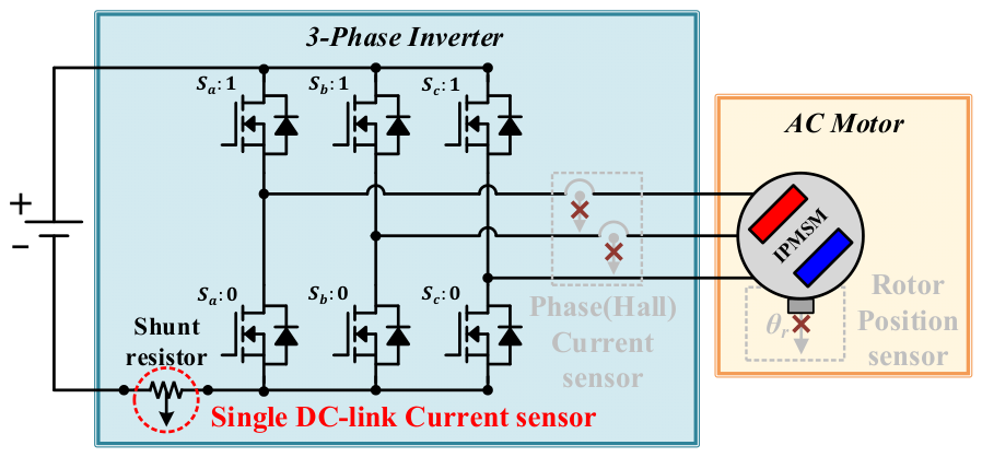
In vector-controlled AC motor drive systems, IPMSMs are widely used owing to their high torque density, high efficiency, and mechanically robust rotor structure. IPMSMs are applied not only to home appliances and compressor systems but also increasingly to traction systems in hybrid and electric vehicles with the ongoing electrification of vehicles. For the vector control of IPMSMs, two or more Hall effect phase current sensors are commonly used to measure motor currents, and a position sensor is used to detect the rotor position. However, the use of multiple sensors increases the system cost and complexity and may compromise overall system reliability. Specifically, position sensors are vulnerable to vibration-induced failures during motor operation, and their installation can be difficult depending on the system configuration, such as in compressor applications. Therefore, as illustrated in Figure 1, a sensor-minimized IPMSM drive system can be implemented by combining current reconstruction using a single DC-link shunt resistor with vector control that operates without a position sensor. This configuration can also be used for fault-tolerant operation in electric vehicle drive systems in the event of phase current or position sensor failures.
Figure 1.
Schematic diagram of the single-shunt drive system without a position sensor.
In an SDS using conventional space vector PWM (SVPWM), phase currents are reconstructed from DC-link currents measured during two active voltage vector intervals within each PWM switching period. However, when the reference voltage vector does not provide sufficient active vector durations, dead zones arise within the voltage hexagon, preventing current reconstruction.
To secure the required DC-link current measurement intervals, previous studies have proposed voltage injection methods such as phase voltage injection and minimum voltage injection (MVI). Each PWM period is divided into measurement and compensation regions: the voltage vector is modified in the measurement region to ensure adequate sampling intervals, while a compensation voltage vector is applied in the compensation region to preserve the average output voltage required for motor control [1,2].
These methods assume that the current variation caused by the measurement voltage injection is sufficiently small, allowing two phase currents to be sequentially measured from the DC-link current and the three-phase currents to be reconstructed. This approach can be readily combined with back EMF-based sensorless control at medium and high speeds, where no additional voltage injection is required for rotor position estimation. At zero and low speeds, however, back EMF is insufficient for reliable position estimation, and high-frequency HF voltage injection-based sensorless control is generally employed.
When HF voltage injection-based sensorless control is combined with an SDS, the rotor position estimation performance can be degraded [3,4,5,6,7,8,9,10,11] because the underlying assumptions of the two methods conflict. HF voltage injection requires sufficiently large current variations for rotor position estimation, whereas single-shunt current reconstruction assumes that the current variation during the voltage injection interval is negligible. Moreover, the HF injection voltage may interfere with the voltage vector modification required for DC-link current measurement, causing voltage distortion. Thus, the inherent characteristics of an SDS lead to current reconstruction errors and voltage distortion, making the simultaneous application of the two methods challenging.
Several studies have addressed this issue [3,4,5,6,7,8,9]. Prediction- or compensation-based current reconstruction methods were proposed in [3,8]; however, their performance depends on motor parameters, and parameter errors can degrade rotor position estimation. The methods in [4,5] employ multiple PWM switching periods and multiple DC-link current samplings within a single control period. Meanwhile, the method in [6] maintains one control period per PWM switching period but employs quasi-edge-aligned PWM, in which the PWM turn-on instants, voltage vector sequence, and zero-vector distribution are rearranged to obtain fixed current sampling intervals and reduce sequential sampling errors. Although the methods in [4,5,6] improve rotor position estimation while preserving parameter independence, they depart from the conventional carrier-based SVPWM structure and require dedicated PWM generation and current sampling procedures, resulting in relatively complex implementation. In addition, the methods in [4,5] require a control period longer than the PWM switching period. A carrier-based method that retains the conventional PWM switching pattern was also proposed in [9]. The magnitude of the rotating HF injection voltage is varied according to the fundamental voltage reference so that the resultant voltage vector remains outside the dead zones. However, a larger HF injection voltage is required as the fundamental voltage increases, which reduces the available voltage margin. Moreover, the method was formulated and validated only for RVI at . Table 1 presents a comparison between the existing HF injection sensorless control methods and the proposed method for SDS.
Table 1.
Comparison of HF injection sensorless control methods for SDS.
This paper extends the preliminary conference paper in [10] by providing more detailed formulations and implementation-oriented descriptions, together with additional analyses and validation. Specifically, the present paper includes extended analyses of conventional PVI and RVI operation; detailed formulations of single-shunt current reconstruction and MVI; formulations of the proposed measurement and compensation voltage vectors and their corresponding offset voltages for PVI and RVI; analyses of current reconstruction errors and voltage distortion-induced rotor position errors; adaptive RVI voltage vector placement; current sampling and phase current THD analyses; complete control block diagrams; and expanded static and dynamic validation. Building on these analyses, carrier-based voltage vector modification methods are proposed for current reconstruction under both pulsating and rotating HF voltage injection. Unlike previous approaches requiring multiple PWM switching periods or more than two DC-link current samplings within one control period, the proposed methods retain a conventional structure with one control period per PWM period and one sampling instant for each of the two phase current measurements, allowing straightforward integration into conventional SVPWM. Furthermore, unlike the variable-magnitude injection approach, the proposed methods satisfy the current reconstruction conditions through the proposed measurement and compensation voltage vector modifications without increasing the HF injection magnitude according to the motor speed or load. Therefore, the HF injection magnitude can be maintained at a predetermined minimum level required for rotor position estimation. By separately arranging the measurement and compensation voltage vectors, the proposed methods accurately capture the HF-induced current variation while satisfying the current reconstruction conditions. The proposed methods are applicable to both PVI and RVI, including HF injection frequencies of and , enabling faster rotor position estimation updates and an improved dynamic response while maintaining stable operation under rated load conditions. Consequently, current reconstruction errors and voltage distortion are reduced without extending the control period, improving rotor position estimation while preserving the parameter-independent characteristic of saliency-based sensorless control. The proposed methods are validated through simulations and experiments.
2. Analysis of Saliency-Based Sensorless Control in SDS
2.1. Single-Shunt Current Reconstruction in SDS
In an SDS, the DC-link current measured through a shunt resistor is expressed by the inverter switching function as follows:
Table 2.
Measurable DC-link current according to voltage vectors.
The measurable DC-link current for each voltage vector is summarized in Table 2. For each active voltage vector, one phase current can be measured through the DC-link current. In contrast, for the zero voltage vectors, and , the DC-link current is zero, rendering phase current information unavailable. For single-shunt current reconstruction, two different phase currents must be measured within one PWM switching period, and the remaining phase current is obtained from
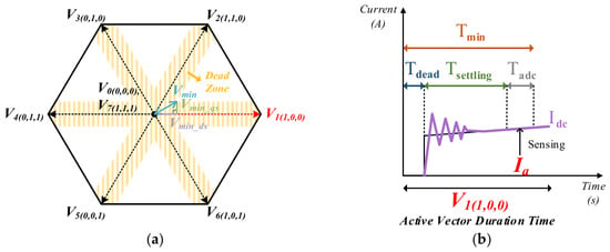
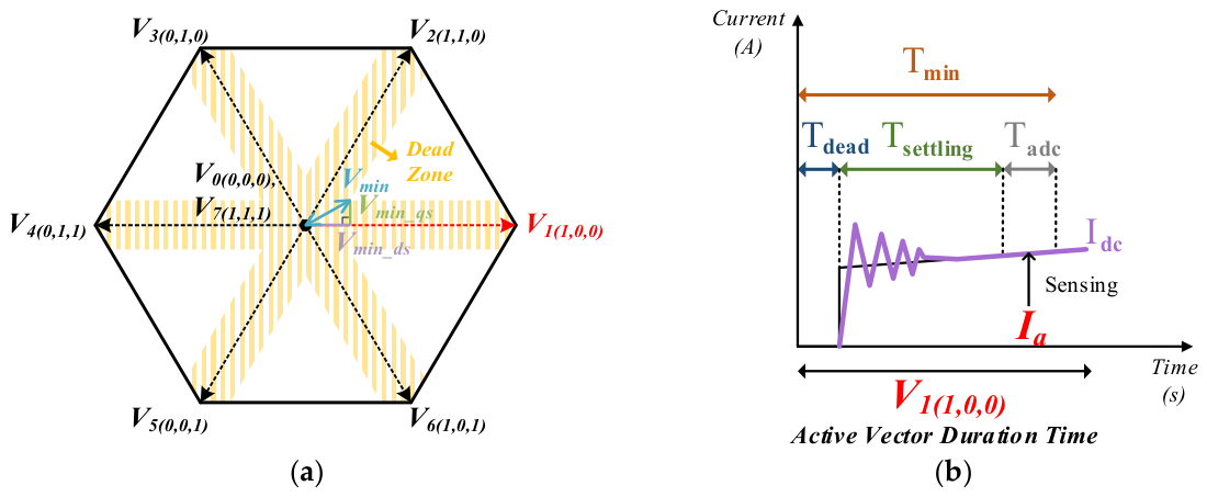
To measure the DC-link current through the shunt resistor, the active voltage vector must be maintained for at least the minimum active vector duration, . As shown in Figure 2b, includes the dead time, the settling time, and the ADC time.
Figure 2.
DC-link current sampling in single-shunt current reconstruction: (a) dead zone in the voltage hexagon; (b) minimum active vector duration time for DC-link current sampling.
When the active vector duration time is shorter than , the DC-link current corresponding to two different phase currents cannot be measured within one PWM switching period. In this case, current reconstruction cannot be performed. The region where current reconstruction is unfeasible is defined as the dead zone in the voltage hexagon. For successful current reconstruction, the voltage vector should be placed outside the dead zone to satisfy .
As shown in Figure 2a, denotes the minimum voltage vector amplitude required to satisfy . The corresponding d- and q-axis voltage amplitudes are denoted by and , respectively. To ensure that the voltage vector is placed outside the dead zone, the d- and q-axis voltage magnitudes should be equal to or larger than and .
In this paper, the MVI method [1] is utilized to satisfy the required minimum voltage vector magnitude for current reconstruction. In the MVI method, one PWM switching period is partitioned into a measurement region and a compensation region.
In the measurement region, the original reference voltage vector for vector control, , is modified by MVI and positioned on the dead zone boundary. The modified vector constitutes the measurement voltage vector, , as shown in Figure 3a. In this region, the two active voltage vectors ensure the condition, and the DC-link currents corresponding to two different phase currents can be sampled for current reconstruction. In the compensation region, the compensation voltage vector, , is implemented to maintain the average output voltage over one PWM switching period. The voltage vectors in the measurement and compensation regions are expressed as
Figure 3.
MVI method for current reconstruction in SDS: (a) location of voltage vectors in the voltage hexagon; (b) PWM switching pattern and DC-link current measurement instant within one PWM switching period.
As shown in Figure 3b, the SDS performs current reconstruction using the DC-link currents measured during the two active voltage vector intervals in the measurement region.
2.2. Conventional Square-Wave HF Voltage Injection Sensorless Control in SDS
HF voltage injection sensorless control methods depend on the waveform, reference frame, and injection location of the injected voltage. This paper considers two square-wave HF voltage injection methods: pulsating voltage injection in the estimated synchronous reference frame and rotating voltage injection in the stationary reference frame. For both sensorless control methods, the current reconstruction errors and voltage distortion resulting from their combination with the SDS are analyzed. Before PVI or RVI sensorless control is initiated, the 180° rotor position ambiguity of the IPMSM is resolved using the initial angle detection method as in [12]. The detected initial angle is used as the initial value of , while the actual rotor position , measured by the position sensor, is used only to evaluate the rotor position estimation error.
2.2.1. Conventional Pulsating HF Voltage Injection (PVI) Sensorless Control in SDS
In this paper, the pulsating square-wave voltage injection method (PVI) in the estimated synchronous reference frame is considered [13]. The square-wave HF voltage is injected into the d-axis of the estimated synchronous reference frame, and the rotor position estimation error is extracted from the q-axis current () variation within the same reference frame. The injected HF voltage and the rotor position estimation error are expressed as follows:
where denotes one PWM switching period, denotes the change in the q-axis current during in the estimated synchronous reference frame, and denotes the square-wave HF voltage with an arbitrary amplitude injected into the d-axis of the estimated synchronous reference frame. The injection frequency of the square-wave HF voltage can be set to , where is the switching frequency and k = 1, 2, 3 ….
As shown in (5), the rotor position estimation error is obtained from the q-axis current variation caused by the injected HF voltage during one sampling period. Therefore, accurate current measurement is critical for accurate rotor position estimation. However, when HF voltage injection sensorless control is applied to an SDS, current reconstruction in the SDS inherently causes rotor position estimation errors.
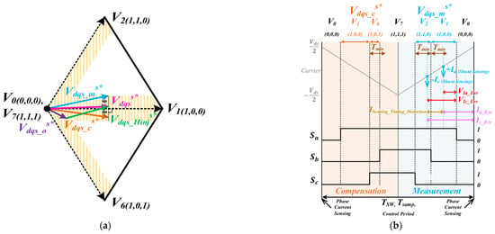
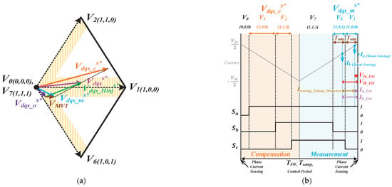
Figure 4a shows the location of the voltage vectors for conventional PVI sensorless control in the voltage hexagon. The total voltage reference vector is the sum of and the HF injection voltage vector, . is divided into the measurement voltage vector, , and the compensation voltage vector, . Figure 4b depicts the voltage vector placement and DC-link current measurement instant within one PWM switching period.
Figure 4.
Conventional PVI sensorless control with current reconstruction in SDS: (a) location of voltage vectors in the voltage hexagon; (b) PWM switching pattern and DC-link current measurement instant within one PWM switching period.
In a phase current sensor system, mid-point sampling is performed at the peak of the PWM carrier, and the phase currents can be accurately measured. In contrast, as shown in Figure 4b, the SDS relies on the DC-link currents during the two active voltage vector intervals. Therefore, mid-point sampling at the peak of the PWM carrier cannot be applied in the SDS. In addition, the two DC-link currents used for current reconstruction are measured at different sampling instants within one PWM switching period. For these reasons, current reconstruction errors are inherent in the SDS.
In sensorless control based on HF voltage injection, the injected HF voltage intentionally produces current variation within one PWM switching period, and the rotor position estimation error is calculated from this current variation. However, due to the current reconstruction errors inherent in the SDS, the current variation required for position error calculation cannot be measured accurately. As the amplitude of the injected voltage increases, the rate of current variation becomes greater, which further increases the current reconstruction errors in the SDS. These errors degrade the rotor position estimation performance of sensorless control based on HF voltage injection.
In an SDS, voltage distortion occurs in addition to current reconstruction errors. In sensorless control based on HF voltage injection, the current variation should be measured after the injected HF voltage has been fully applied. However, in an SDS, the DC-link current is measured during the active voltage vector intervals used for current reconstruction. Therefore, the current is reconstructed from DC-link current measurements acquired before the injected HF voltage has been fully applied. As a result, the HF voltage reflected in the reconstructed current differs from the intended injected HF voltage, causing voltage distortion. In addition, the MVI voltage required to satisfy is injected together with the HF voltage used for sensorless control. These two voltage injections interfere with each other, causing additional voltage distortion. Consequently, this voltage distortion further increases the rotor position estimation errors in sensorless control based on HF voltage injection when combined with an SDS.
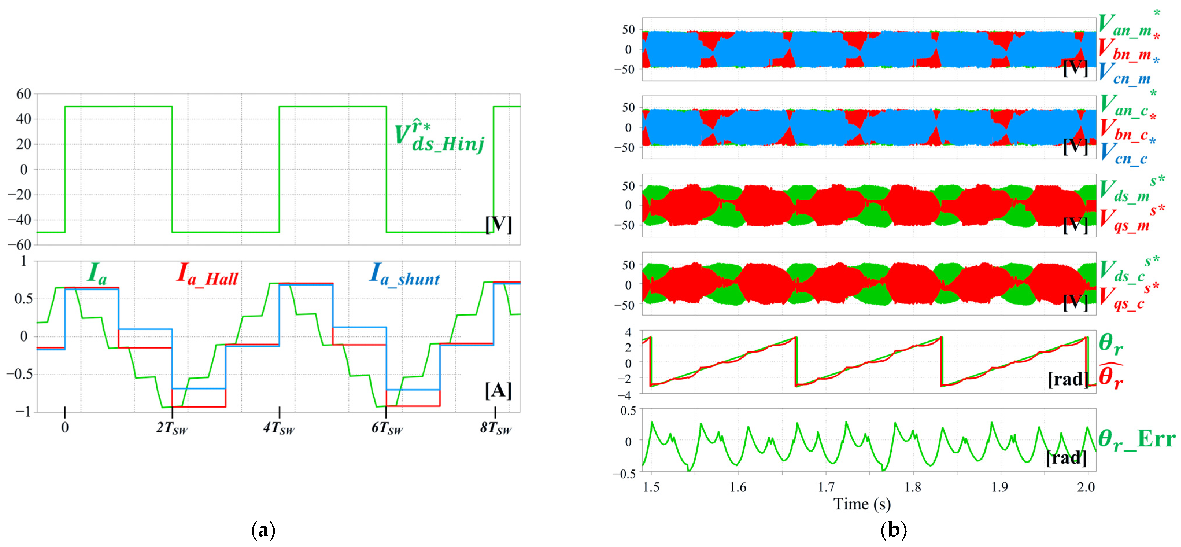
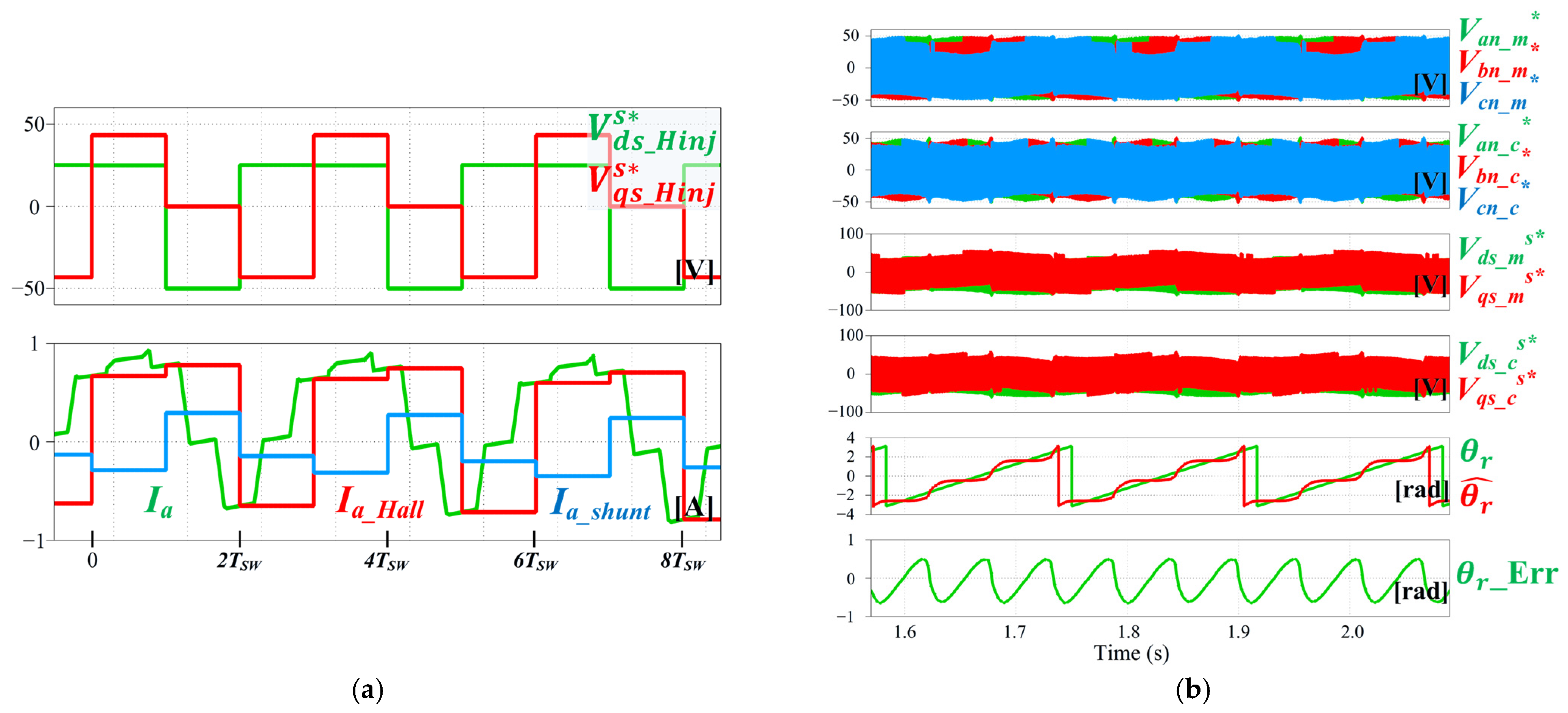
Figure 5 shows the simulation results of the position estimation performance of the conventional PVI sensorless control in an SDS at 90 r/min under no-load conditions. The switching frequency is 5 kHz, and the injected HF voltage has an amplitude of 50 V and a frequency of . In Figure 5b, and denote the three-phase inverter pole voltage references corresponding to the measurement and compensation voltage vectors, respectively, where .
Figure 5.
Simulation results regarding the position estimation performance of conventional PVI sensorless control in SDS: (a) current reconstruction error; (b) voltage references and rotor position estimation error.
As shown in Figure 5a, the phase current sensor system accurately measures the actual phase currents through mid-point sampling, whereas the reconstructed currents in the SDS contain current reconstruction errors. Due to these errors and the associated voltage distortion, a ripple is generated in the q-axis current of the estimated synchronous reference frame used in (5), resulting in rotor position estimation errors. As shown in Figure 5b, a sixth-harmonic component is produced in the estimated rotor position because encounters the dead zone six times during one rotation in the voltage hexagon. The maximum electrical position error caused by this sixth-harmonic component reaches approximately 43°, indicating a significant rotor position estimation error. Consequently, rotor position estimation errors occur.
2.2.2. Conventional Rotating HF Voltage Injection (RVI) Sensorless Control in SDS
In this paper, the rotating square-wave voltage injection method in the stationary reference frame is examined [13]. The square-wave HF voltage is injected into the stationary reference frame independently of the fundamental frequency. The estimated rotor position, , is derived from the d- and q-axis current variations, and , in the stationary reference frame. The injected HF voltage and the estimated rotor position are defined as
where
As shown in (6), the estimated rotor position, , is obtained from the d- and q-axis current variations induced by the injected HF voltage during one sampling period. Therefore, accurate current measurement is critical for precise rotor position estimation. As in PVI sensorless control, when RVI sensorless control is integrated with an SDS, current reconstruction in the SDS also causes rotor position estimation errors.
As in [13], this paper examines the RVI method wherein the HF voltage is injected at three fixed points in the voltage hexagon. If the injected HF voltage is located inside the dead zone, the MVI voltage is further injected to satisfy for the current reconstruction. Since HF voltage injection sensorless control is primarily employed in the zero- and low-speed regions, the magnitude of is relatively small compared with the magnitude of the injected HF voltage. Therefore, the total voltage reference vector is predominantly located near the three HF voltage injection points and tends to be located inside the dead zone. Thus, MVI voltage injection is often applied to satisfy . The frequent conflict between the HF injection voltage and the MVI voltage further increases voltage distortion. For the same reasons discussed in Section 2.2.1, current reconstruction errors and voltage distortion degrade the rotor position estimation performance of RVI sensorless control in the SDS.
Figure 6a shows the location of the voltage vectors for the conventional RVI sensorless control in the voltage hexagon when the HF voltage is injected into the current reconstruction dead zone. In this representative case, the three HF injection voltage vectors, , , and , are sequentially applied in the stationary reference frame at 60°, 180°, and 300°. Figure 6b depicts the corresponding voltage vector placement and DC-link current measurement instants within one PWM switching period. As shown in Figure 6b, the first active vector duration in the measurement region is longer than the second active vector duration. Therefore, the interval between the two DC-link current measurement instants becomes large within one PWM switching period. Since the injected HF voltage intentionally produces a large current variation, the increased interval between the two measurement instants results in a larger current reconstruction error.
Figure 6.
Conventional RVI sensorless control with current reconstruction in SDS: (a) location of voltage vectors in the voltage hexagon; (b) PWM switching pattern and DC-link current measurement instant within one PWM switching period.
Figure 7 shows the simulation results regarding the position estimation performance of conventional RVI sensorless control in an SDS with 60°, 180°, and 300° HF voltage injection at 90 r/min under no-load conditions. The switching frequency is 5 kHz, and the injected HF voltage has an amplitude of 50 V and a frequency of .
Figure 7.
Simulation results regarding the position estimation performance of conventional RVI sensorless control in SDS for 60°, 180°, and 300° HF voltage injection: (a) current reconstruction error; (b) voltage references and rotor position estimation error.
As shown in Figure 7a, the HF voltage is injected at three fixed points inside the current reconstruction dead zone. In low-speed operation, where HF voltage injection sensorless control is mainly used, the fundamental voltage vector for vector control, , is much smaller than the injected HF voltage vector. Therefore, the total voltage reference vector, , is mainly located near the HF injection voltage vectors. When the HF injection voltage vectors are placed inside the dead zone, is frequently located inside or near the dead zone region around the injection points. In this case, MVI is repeatedly applied to satisfy the current reconstruction condition. As a result, the repeated application of MVI at the three fixed injection positions inevitably produces a third-harmonic component in the estimated rotor position, as shown in Figure 7b. The maximum electrical position error caused by this third-harmonic component reaches approximately 39°, indicating a significant rotor position estimation error.
3. Proposed Carrier-Based Voltage Vector Modification Methods
3.1. Proposed Method for Pulsating HF Voltage Injection Sensorless Control in SDS
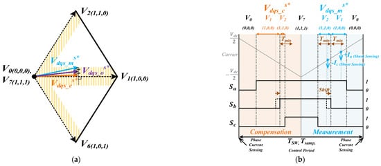
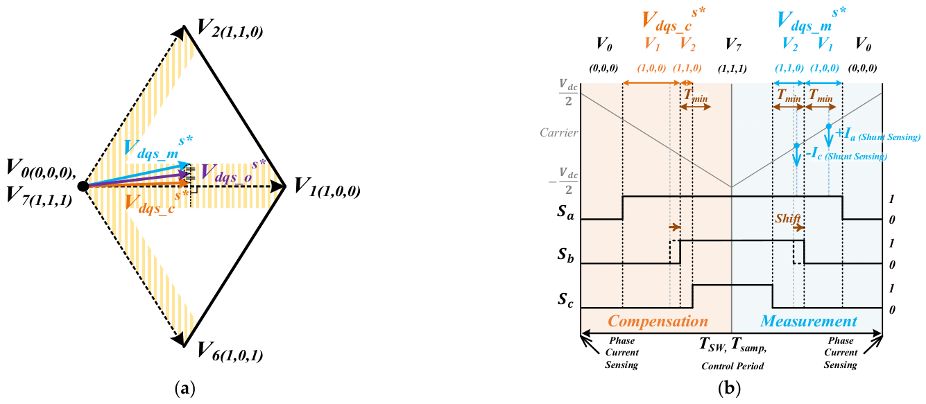
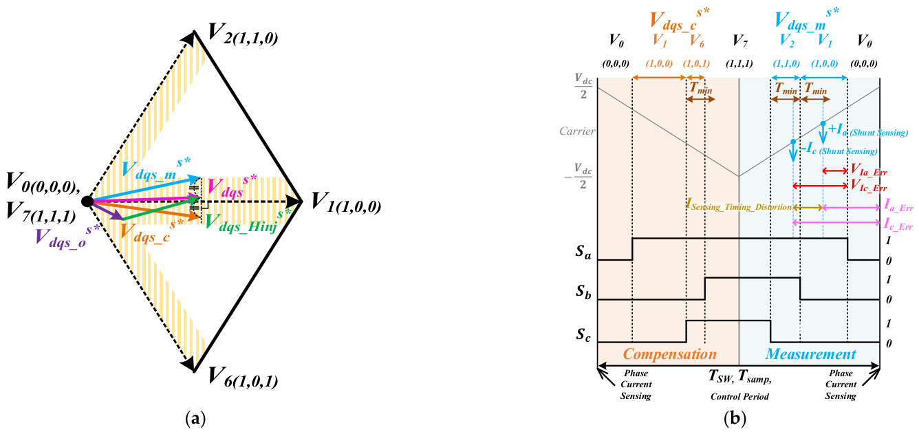
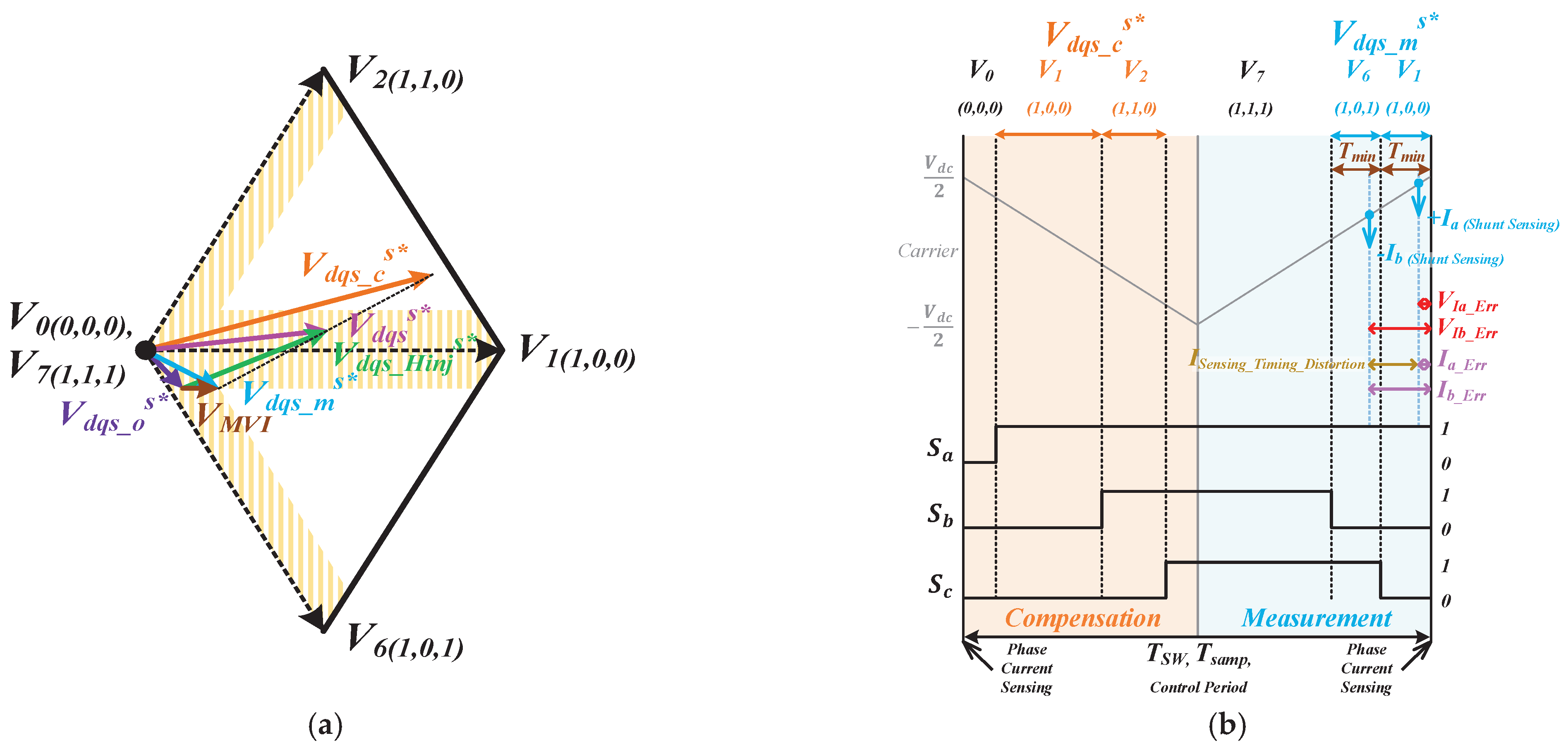
As shown in Figure 8, in the proposed method, the duration of each active voltage vector in the measurement region is fixed at . Consequently, the interval between the two DC-link current measurement instants is minimized, and the current reconstruction errors are reduced. An offset voltage is introduced to align the active voltage vectors near the carrier peak, which makes the DC-link current measurement condition close to the mid-point sampling of a phase current sensor system.
Figure 8.
Proposed PVI sensorless control methods with current reconstruction in SDS: (a) location of voltage vectors in the voltage hexagon; (b) PWM switching pattern and DC-link current measurement instant within one PWM switching period.
In the compensation region, the voltage not utilized in the measurement region is compensated to maintain the average output voltage over one PWM switching period. Additionally, the HF injection voltage is positioned in the compensation region prior to the measurement region. Thus, the current variation induced by the injected HF voltage can be accurately measured within the measurement region, and voltage distortion is reduced. The voltage vectors in the measurement and compensation regions are expressed as
To position the active voltage vectors near the peak of the PWM carrier and allow the DC-link current measurement condition to approximate the mid-point sampling condition of a phase current sensor system, the offset voltage in the measurement region is expressed as
The measurement voltage vector, , is first transformed into the three-phase inverter pole voltage references. In (9), represents the maximum pole voltage reference among the three-phase inverter pole voltage references in the measurement region. is applied uniformly to all pole voltage references in the measurement region. Consequently, the DC-link current measurement instant is positioned near the peak of the PWM carrier, making the measurement condition similar to the mid-point sampling condition of a phase current sensor system.
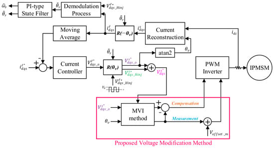
Figure 9 shows the overall vector control block diagram of the proposed PVI method for sensorless control in SDS.
Figure 9.
Overall control block diagram for the proposed PVI sensorless control in SDS.
Figure 10.
Simulation results regarding the position estimation performance of the proposed PVI sensorless control in SDS at : (a) current reconstruction error; (b) voltage references and rotor position estimation error.
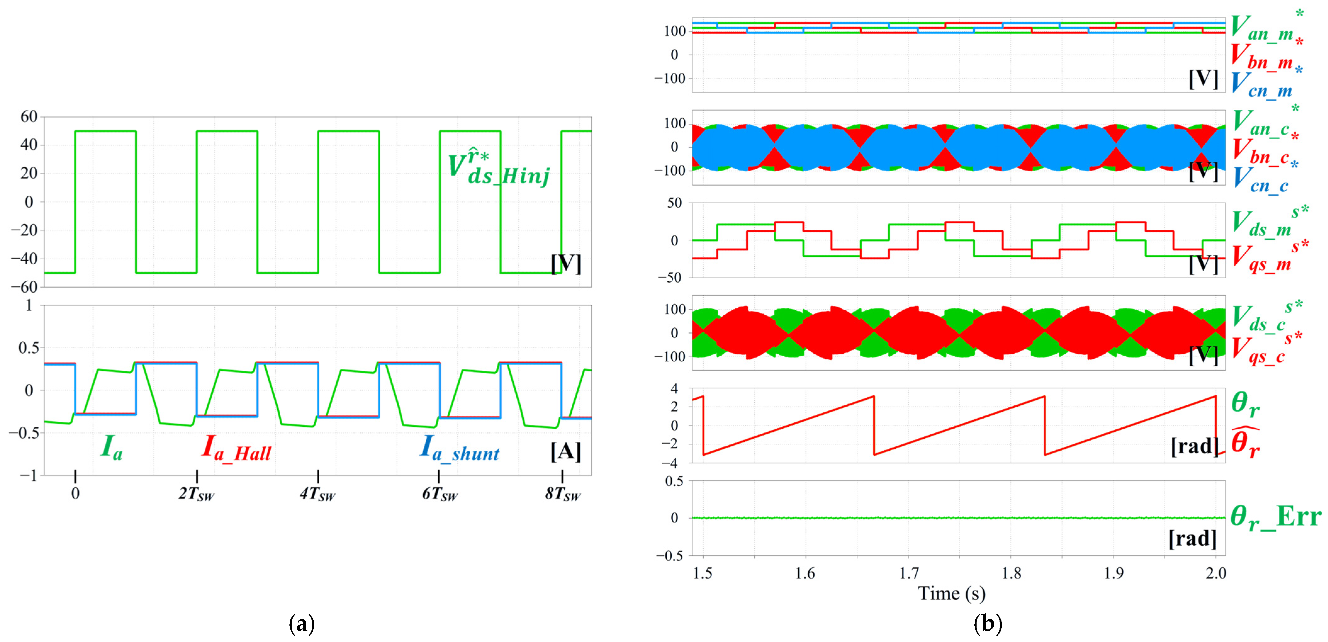
Figure 10 shows the simulation results regarding the position estimation performance of the proposed PVI sensorless control in the SDS at 90 r/min under no-load conditions. The switching frequency is 5 kHz, and the injected HF voltage has an amplitude of 50 V. The injection frequency is .
Figure 10b demonstrates that the measurement voltage vector is constrained to the minimum voltage magnitude required to satisfy and is fixed at six points in the voltage hexagon during one revolution of the voltage vector. Therefore, its magnitude remains relatively small. In contrast, the compensation voltage vector has a much larger magnitude than the measurement voltage vector because it must apply the HF injection voltage and compensate for the voltage not applied in the measurement region to maintain the average output voltage over one PWM switching period. Consequently, contains the HF voltage component and is applied over a wide region of the voltage hexagon regardless of the dead zone.
As shown in Figure 10a, the reconstructed current in the SDS closely matches the current measured by the phase current sensor system, and the current reconstruction errors are significantly reduced. The reduced current reconstruction errors suppress the q-axis current ripple caused by the injected HF voltage, thereby improving the rotor position estimation accuracy. In addition, Figure 10b shows that the maximum electrical position error of the proposed method is only 0.006°, which can be regarded as nearly zero. Compared with conventional PVI sensorless control, the position error is reduced by approximately 43°, confirming the effective suppression of the sixth-harmonic component in the estimated rotor position. These results demonstrate that the proposed method improves the position estimation performance of PVI sensorless control in the SDS.
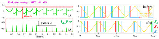
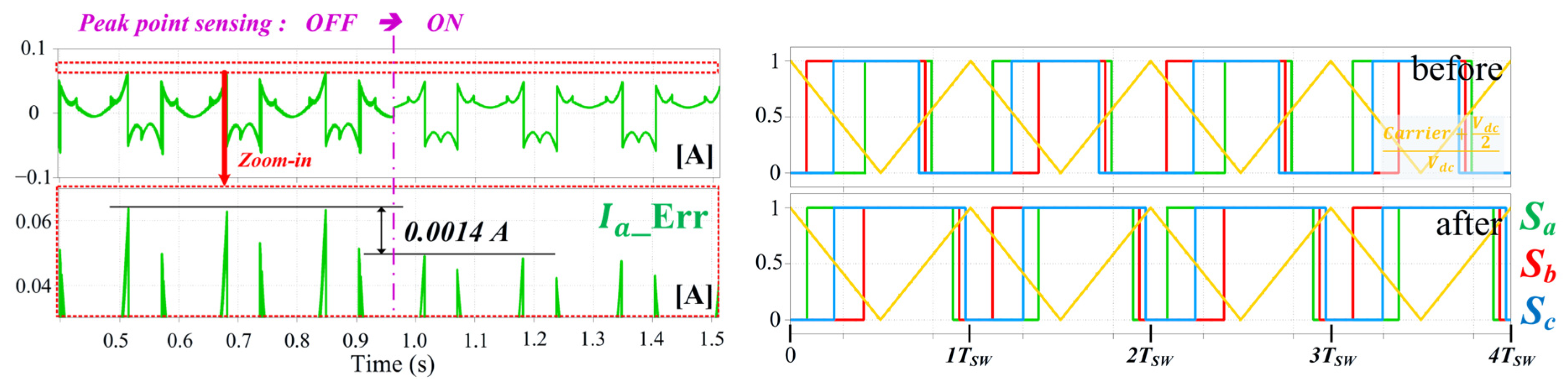
Figure 11 depicts the current reconstruction errors before and after offset voltage addition at . By implementing the offset voltage, the DC-link current measurement instants are shifted closer to the carrier peak, rendering the DC-link current measurement closer to the mid-point sampling condition of the phase current sensor system. The results show that the magnitude of the current reconstruction errors is reduced by the offset voltage addition.
Figure 11.
Effects of offset voltage addition in the proposed PVI sensorless control: before and after offset voltage addition at .
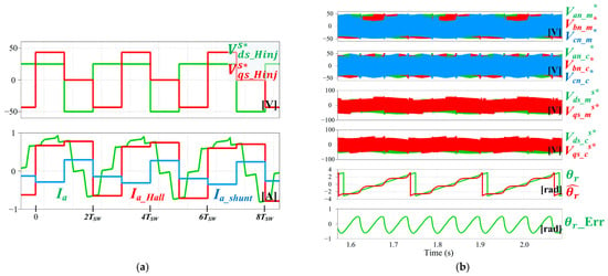
Figure 12 shows representative a-phase current waveforms obtained using the conventional and proposed PVI sensorless control methods in the SDS at 90 r/min under a 50% load. The switching frequency is 5 kHz, the injected HF voltage amplitude is 50 V, and the injection frequency is . Because the conventional method cannot maintain stable vector control at , the comparison is conducted at . At this injection frequency, the conventional method is controllable in simulation only up to a 50% load. As shown in Figure 12, the proposed method exhibits a lower a-phase current THD than the conventional method at both 25% and 50% loads. Moreover, whereas the conventional method becomes uncontrollable above a 50% load, the proposed method maintains stable sensorless control up to the rated load condition, with the THD decreasing from 68% at a 25% load to 18% at the rated load. These results confirm that the proposed method outperforms the conventional method in terms of the phase current THD.
Figure 12.
Comparison of a-phase current waveforms at 50% load and phase current THD under different load conditions for the conventional and proposed PVI methods at .
3.2. Proposed Method for Rotating HF Voltage Injection Sensorless Control in SDS
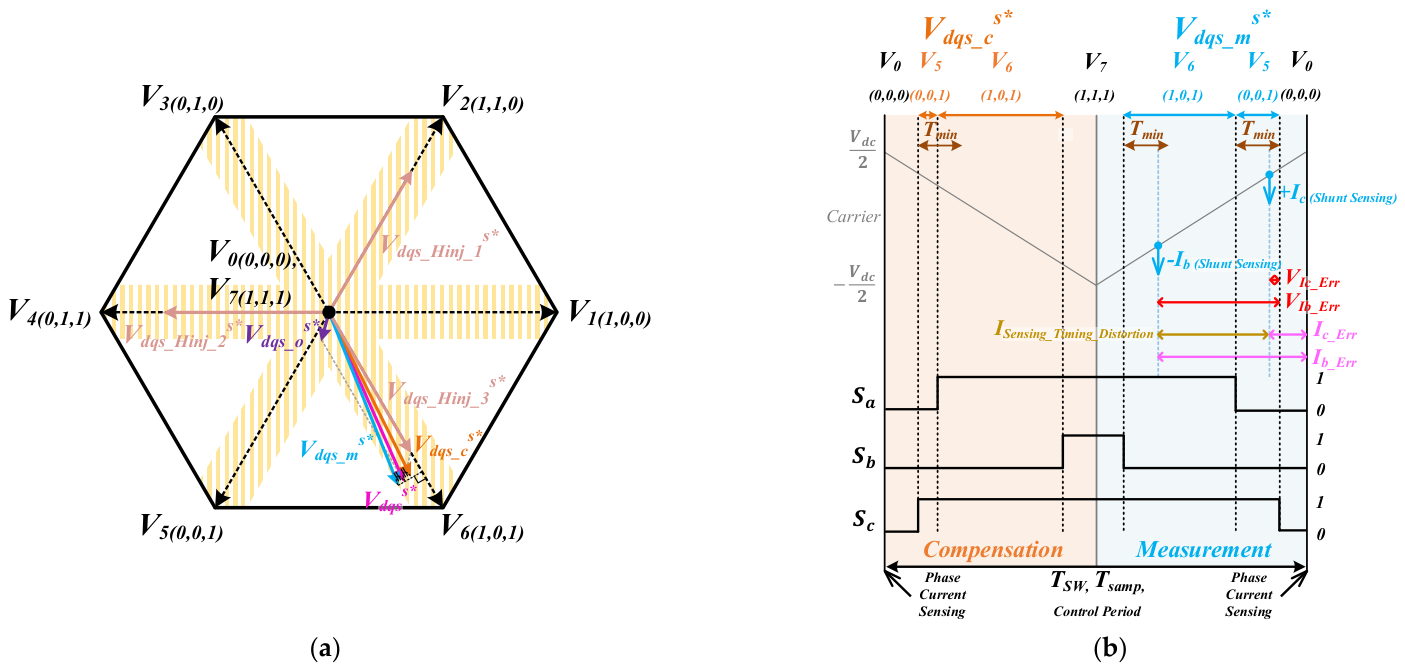
As shown in Figure 13, in the proposed method, the HF voltage vectors are injected at three fixed locations on the boundary of the dead zone. Although the HF voltage vectors can be injected completely outside the dead zone, they are injected at the proposed locations to minimize voltage distortion and current reconstruction errors. At these injection points, the duration of each active voltage vector is greater than or equal to . Therefore, the DC-link currents can be measured in the measurement region without additional MVI voltage injection. At the proposed HF voltage injection points, the duration of the first active voltage vector in the measurement region is longer than , whereas the duration of the second active voltage vector is fixed at , as shown in Figure 13b. To reduce current reconstruction errors, the current sampling instant for the first active voltage vector is placed near the end of the active vector interval. Unlike the conventional current measurement method in the SDS, in which the DC-link current is measured at a fixed instant within from the beginning of the active voltage vector, the proposed method measures the DC-link current at an instant for which only the ADC time remains before the end of the first active voltage vector. Consequently, the interval between the two DC-link current measurement instants is minimized, thereby reducing the current reconstruction errors. The current measurement trigger voltage for measuring the DC-link current near the end of the first active voltage vector is expressed as
where represents the middle pole voltage reference among the three-phase inverter pole voltage references in the measurement region, and is the ADC time for the measured current. By minimizing the interval between the two current measurement instants, the current reconstruction errors are further reduced. In addition, because the DC-link current is measured after the HF voltage has been sufficiently applied, the current variation caused by the injected HF voltage can be accurately reflected in the reconstructed current. Furthermore, because the HF voltage vectors are injected on the dead zone boundary, additional MVI voltage injection for current reconstruction is not required. Consequently, the voltage distortion caused by the interaction between the HF injection voltage and the MVI voltage is eliminated. As in the proposed PVI method, the same offset voltage, in (9), is added to all three-phase inverter pole voltage references in the measurement region. This adjustment positions the DC-link current measurement instant near the peak of the PWM carrier, making the measurement condition similar to the mid-point sampling condition of a phase current sensor system. In the compensation region, because MVI voltage injection is not applied in the measurement region, only is used to maintain the average output voltage over one PWM switching period. The voltage vectors in the measurement and compensation regions are expressed as
In the proposed RVI method, the injected HF voltage is used not only for sensorless control but also for current reconstruction. Therefore, the HF voltage vector should be placed on the dead zone boundary. As shown in Figure 13a, the HF voltage vector is positioned along the dead zone boundary to satisfy regardless of the amplitude of the injected HF voltage. The d- and q-axis voltage magnitudes required to move the injected HF voltage vector along the dead zone boundary according to the amplitude of the injected HF voltage are expressed as follows:
where is the minimum q-axis voltage amplitude required to satisfy , as shown in Figure 2a. is the reference amplitude of the injected HF voltage, and is the actual amplitude of the injected HF voltage. In (13), the factor is employed because the injected HF voltage is doubled in the measurement region, as expressed in (11). The rotating HF voltage vectors are aligned on the dead zone boundary through the application of rotation transformations of 60°, 180°, and 300° to the d- and q-axis voltage amplitudes in (13) and (14).
Figure 14 shows the overall vector control block diagram of the proposed RVI method for sensorless control in SDS.
Figure 13.
Proposed RVI sensorless control methods with current reconstruction in SDS: (a) location of voltage vectors in the voltage hexagon; (b) PWM switching pattern and DC-link current measurement instant within one PWM switching period.
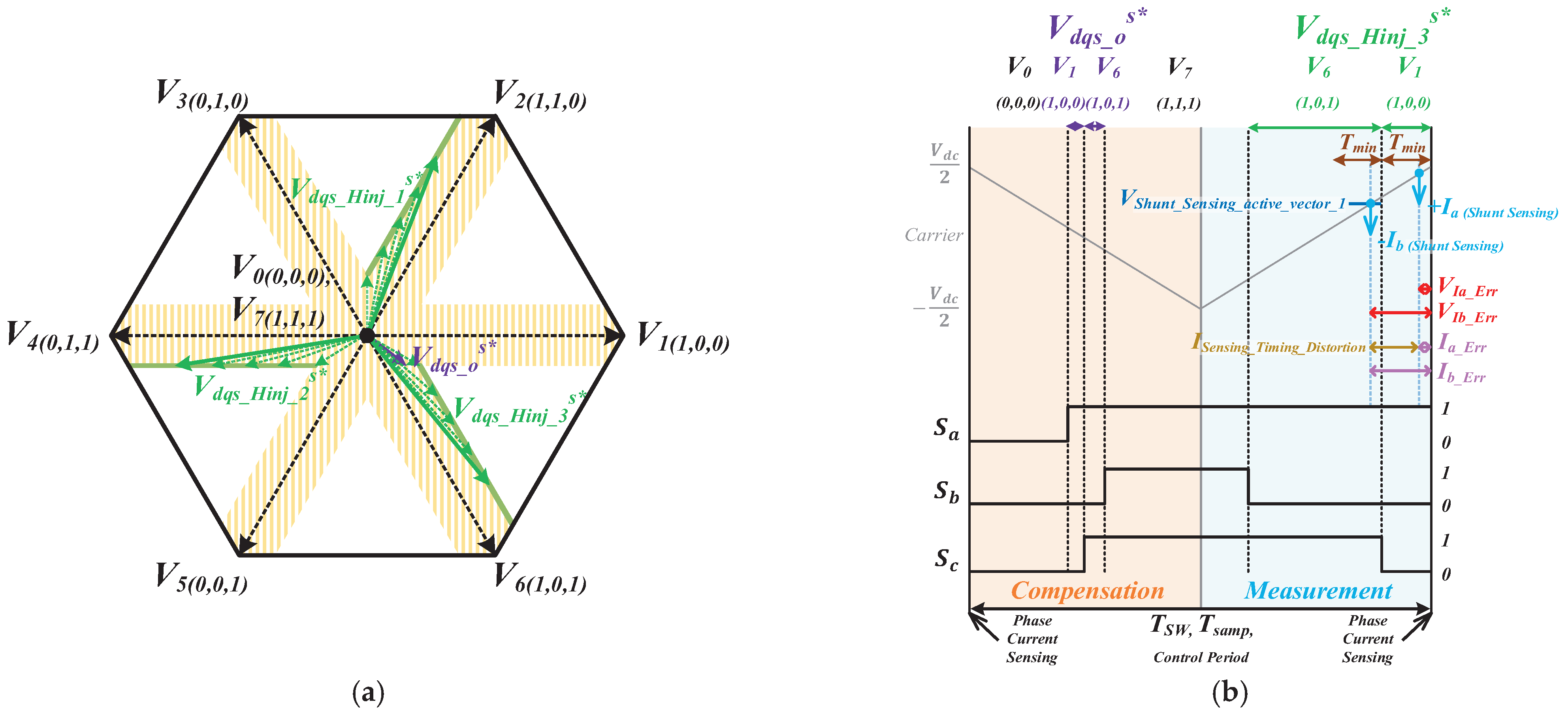
Figure 14.
Overall control block diagram for the proposed RVI sensorless control in SDS.
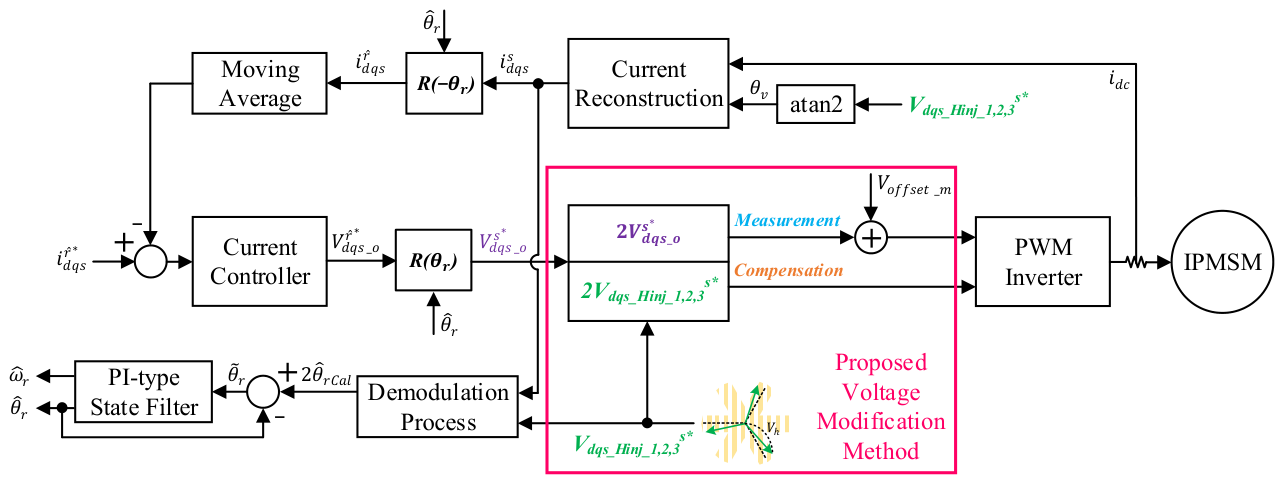
Figure 15.
Simulation results regarding the position estimation performance of the proposed RVI sensorless control in SDS with dead zone boundary HF voltage injection: (a) current reconstruction error; (b) voltage references and rotor position estimation error.
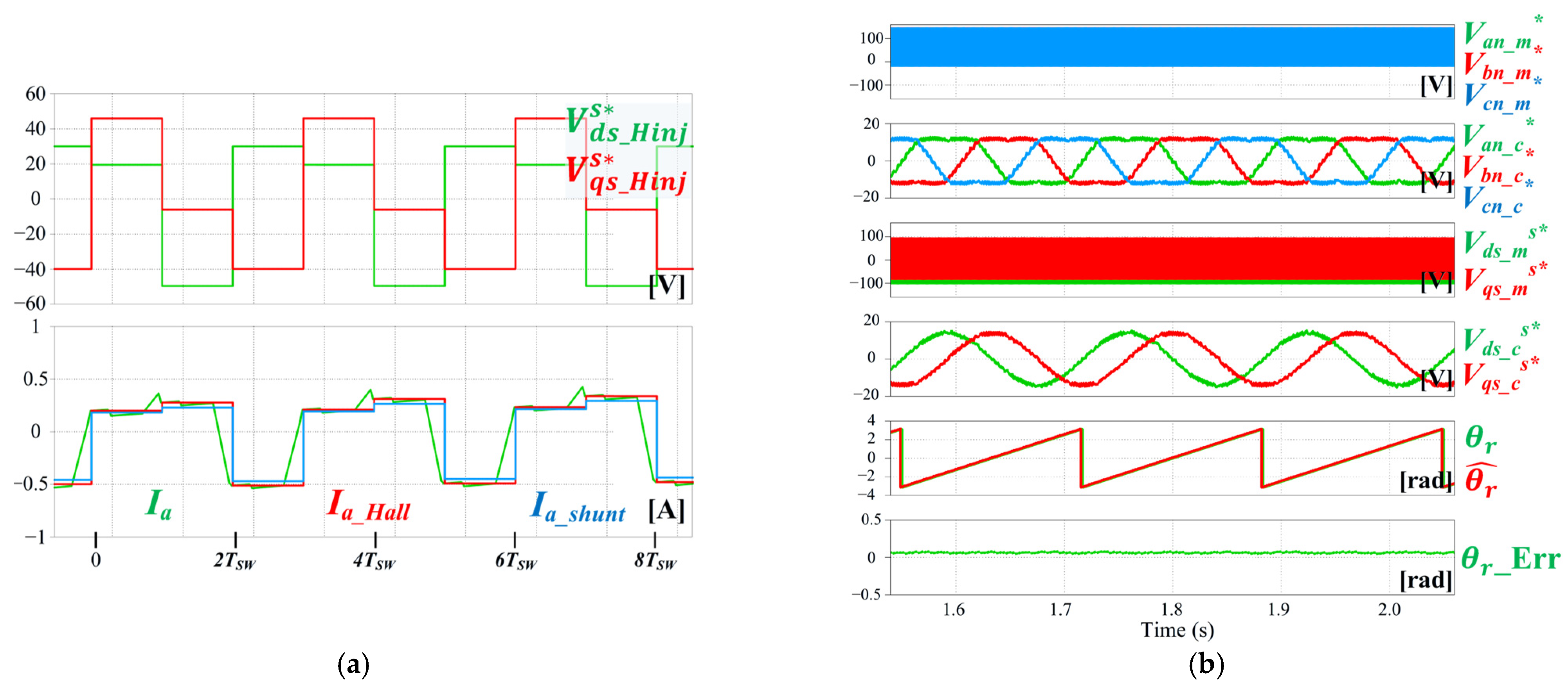
Figure 16.
Effects of offset voltage addition in the proposed RVI sensorless control: before and after offset voltage addition.
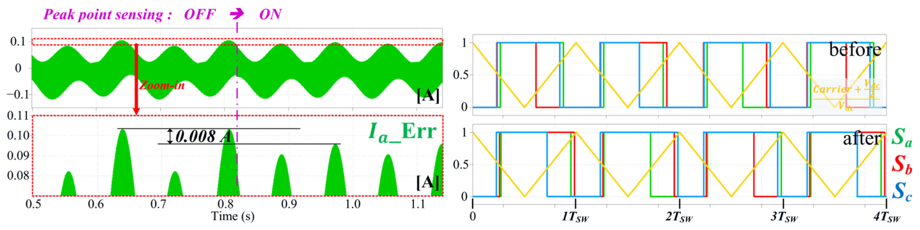
Figure 15 shows the simulation results regarding the position estimation performance of the proposed RVI sensorless control in the SDS at 90 r/min under no-load conditions. The switching frequency is 5 kHz, and the injected HF voltage has an amplitude of 50 V and a frequency of . The current reconstruction errors are significantly reduced compared with those of conventional RVI sensorless control. Figure 15b shows that the rotor position is accurately estimated. In addition, the maximum electrical position error of the proposed method is only 0.6°. Compared with conventional RVI sensorless control, the position error decreases from approximately 39° to 0.6°, confirming that the third-harmonic component in the estimated rotor position is effectively reduced by placing the HF voltage on the dead zone boundary. These results demonstrate that the proposed method improves the position estimation performance of RVI sensorless control in the SDS, and the current reconstruction error reduction upon adding the offset voltage is presented in Figure 16.
Consistent with the PVI results, Figure 17 shows that the proposed RVI method exhibits a lower phase current THD than the conventional method. The THD is reduced from 200% to 95% at a 25% load and from 92% to 50% at a 50% load. Moreover, whereas the conventional method becomes uncontrollable above a 50% load, the proposed method maintains stable sensorless control up to the rated load condition.
Figure 17.
Comparison of a-phase current waveforms at 50% load and phase current THD under different load conditions for the conventional and proposed RVI methods.
4. Experimental Results
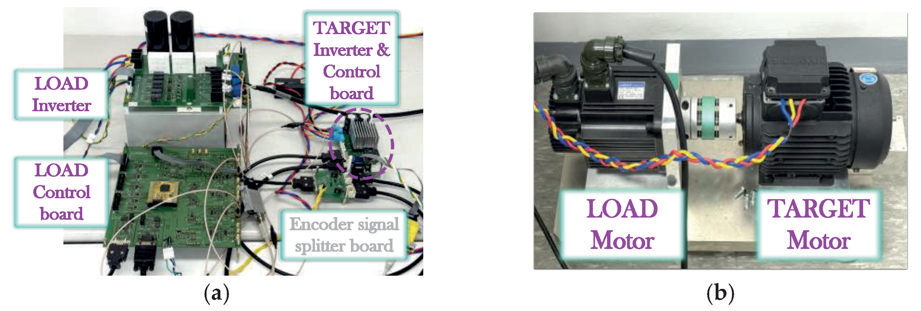
Experiments were conducted to verify the proposed PVI and RVI sensorless control methods in the SDS. Table 3 lists the parameters of the IPMSM drive system with the SDS inverter used in the experiments, and Figure 18 shows the experimental setup.
Table 3.
Experimental parameters of the single-shunt IPMSM drive system.
Figure 18.
Experimental setup of the IPMSM drive system with an SDS inverter: (a) inverters and control boards; (b) MG set with target motor and load motor.
4.1. Conventional Method for PVI Sensorless Control in SDS
Figure 19 shows the experimental waveforms of the conventional PVI sensorless control in the SDS with HF voltage injection. The amplitude of the injected HF voltage is 50 V, and the experiment was conducted at 90 r/min under half-load conditions. Consistent with the simulation results, a sixth-harmonic component appears in the estimated rotor position. The experimental results show that rotor position estimation errors occur because of current reconstruction errors and voltage distortion.
Figure 19.
Experimental results regarding the position estimation performance of conventional PVI sensorless control in SDS at HF voltage injection.
4.2. Proposed Method for PVI Sensorless Control in SDS
Figure 20 presents the experimental waveforms for the proposed PVI sensorless control in the SDS with HF voltage injection. The injected HF voltage amplitude is 50 V, and the experiment is conducted at 90 r/min under rated load conditions. The experimental results are consistent with the simulation results. Compared with conventional PVI sensorless control, the proposed method reduces both the current reconstruction and rotor position estimation errors. In addition, the sixth-harmonic component in the estimated rotor position is effectively suppressed. These results demonstrate that the proposed method improves the current reconstruction and position estimation performance of PVI sensorless control in the SDS.
Figure 20.
Experimental results regarding the position estimation performance of the proposed PVI sensorless control in SDS: HF voltage injection.
Figure 21 shows the experimental waveforms utilized to verify the position estimation performance of the proposed PVI sensorless control through the application of an artificial rotor position error. In this experiment, the HF voltage is injected into the d-axis of the erroneous estimated synchronous reference frame, and the position estimation error is derived from the q-axis current variation in the same reference frame. The amplitude of the injected HF voltage is 50 V, and the experiment is performed at 90 r/min under rated load conditions and a frequency of . As shown in Figure 21a, when a +50° position error is intentionally introduced into the estimated rotor position, the rotor position estimation error is measured as approximately −0.8 rad, corresponding to −45.84°. Similarly, as shown in Figure 21b, when a −50° position error is applied, the rotor position estimation error is measured as approximately 0.8 rad, corresponding to 45.84°. These results indicate that the applied position errors are estimated with relatively high accuracy. The magnitude of the measured estimation error differs from that of the applied position error by approximately 4.16° in terms of the electrical angle. Since the tested motor has four pole pairs, this difference corresponds to approximately 1.04° in terms of the mechanical angle. In addition, the ripple amplitudes of the estimated position and the position estimation error are reduced. These results indicate that the proposed estimator identifies the applied position error with a relatively small deviation while reducing estimation ripple, thereby providing reasonably accurate rotor position estimation under the tested conditions. These results confirm that the proposed PVI sensorless control method accurately estimates the rotor position in the SDS.
Figure 21.
Experimental results regarding the position estimation performance of the proposed PVI sensorless control method with artificial position error injection: (a) +50° position error application; (b) −50° position error application.
Figure 22 shows the dynamic performance of the proposed PVI sensorless control in the SDS with HF voltage injection. The injected HF voltage amplitude is 50 V. Figure 22a presents the step speed response when the speed reference is changed from 90 r/min to −90 r/min and then back to 90 r/min under rated load conditions, while Figure 22b shows the step load response at 90 r/min during step changes between the positive and negative rated load conditions. The proposed method maintains stable sensorless control during both step speed and step load variations under rated load conditions. Moreover, although the conventional method cannot maintain stable sensorless control with injection, the experimental results confirm that the proposed method enables stable sensorless control at this injection frequency.
Figure 22.
Dynamic performance of the proposed PVI sensorless control in SDS at HF voltage injection: (a) step speed response under rated load condition; (b) step load response under rated load condition.
4.3. Proposed Method for RVI Sensorless Control in SDS
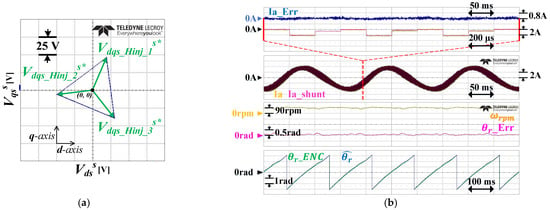
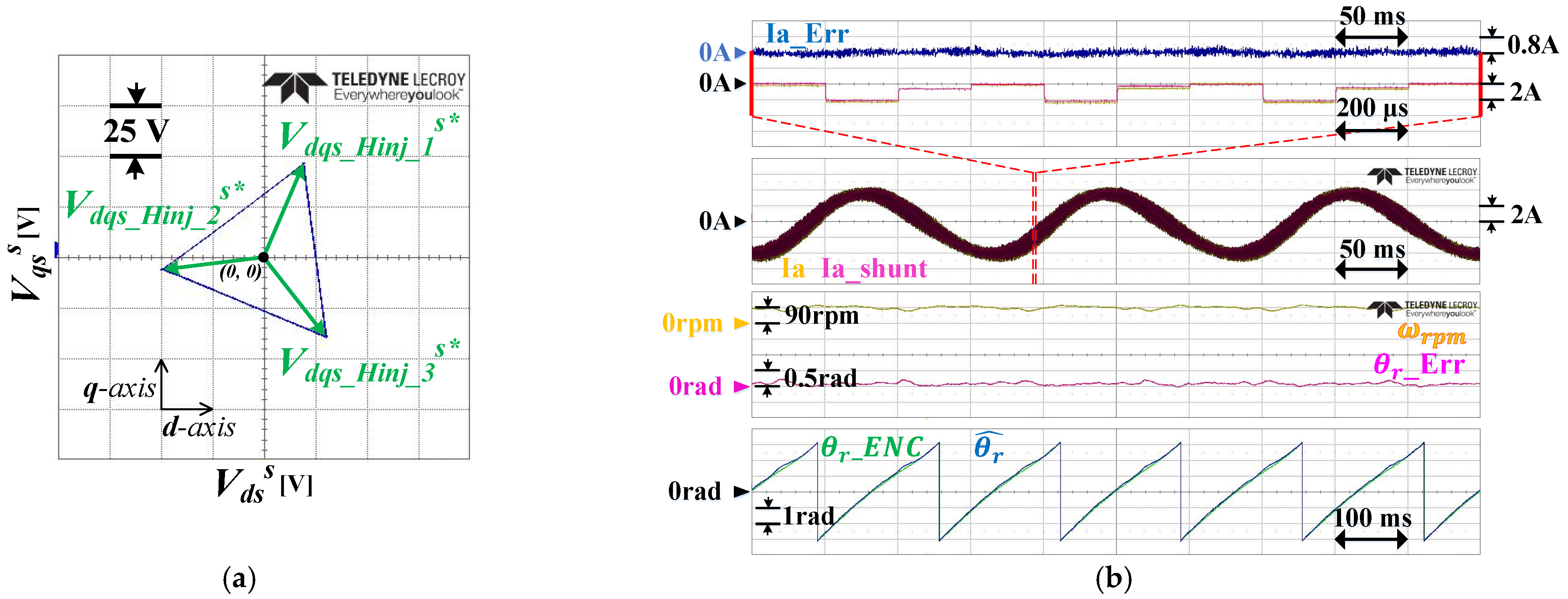
Figure 23 shows the experimental waveforms for the proposed RVI sensorless control in the SDS at HF voltage injection. The amplitude of the injected HF voltage is 50 V, and the experiment was performed at 90 r/min under rated load conditions. The experimental results show the same tendency as the simulation results. The current reconstruction errors are significantly reduced compared with those of conventional RVI sensorless control, and the rotor position estimation accuracy is correspondingly improved. In addition, the third-harmonic component in the estimated rotor position is considerably reduced compared with conventional RVI sensorless control. These results show that the proposed method improves the current reconstruction and position estimation performance of RVI sensorless control in the SDS.
Figure 23.
Experimental results regarding the position estimation performance of the proposed RVI sensorless control in SDS at HF voltage injection: (a) injected HF voltage vector in the voltage hexagon; (b) current reconstruction error and rotor position estimation performance.
Figure 24 shows the dynamic performance of the proposed RVI sensorless control in the SDS under speed control mode. The injected HF voltage has an amplitude of 50 V and a frequency of . Figure 24a presents the step speed response when the speed reference is changed from 90 r/min to −90 r/min and then back to 90 r/min under rated load conditions, while Figure 24b shows the step load response at 90 r/min during step changes between positive and negative rated load conditions. The proposed RVI method maintains stable sensorless control during both step speed and step load variations under rated load conditions.
Figure 24.
Dynamic performance of the proposed RVI sensorless control in SDS at HF voltage injection: (a) step speed response under rated load condition; (b) step load response under rated load condition.
5. Conclusions
This paper analyzed the current reconstruction errors and voltage distortion arising when HF voltage injection-based sensorless control is combined with single-shunt current reconstruction in an IPMSM SDS. Based on this analysis, carrier-based voltage vector modification methods were proposed for PVI and RVI. By optimizing the placement of the measurement and compensation voltage vectors and the DC-link current sampling instants, the proposed methods accurately reflect HF-induced current variations in the reconstructed currents while reducing voltage distortion. They preserve the conventional carrier-based PWM structure, with one control period per PWM period and one sampling instant for each of the two phase current measurements, thereby avoiding multiple PWM periods and prediction-based compensation while retaining parameter independence. Simulation and experimental results showed that the proposed methods considerably reduced the dominant sixth- and third-harmonic rotor position errors in conventional PVI and RVI, respectively, and maintained stable vector control performance under rated load, step load, and step speed conditions.
Author Contributions
Conceptualization, Y.H.; Methodology, M.K. and Y.H.; Software, M.K.; Validation, M.K.; Formal analysis, M.K.; Investigation, M.K. and Y.H.; Data curation, M.K.; Writing—original draft, M.K.; Writing—review & editing, M.K. and Y.H.; Visualization, M.K.; Supervision, Y.H.; Project administration, Y.H.; Funding acquisition, Y.H. All authors have read and agreed to the published version of the manuscript.
Funding
This research was funded by the National Research Foundation of Korea (NRF) grant number RS-2025-20242968.
Data Availability Statement
The original contributions presented in this study are included in the article. Further inquiries can be directed to the corresponding author.
Conflicts of Interest
The authors declare no conflict of interest.
References
- Ha, J.-I. Voltage injection method for three-phase current reconstruction in PWM inverters using a single sensor. IEEE Trans. Power Electron. 2009, 24, 767–775. [Google Scholar] [CrossRef] [Scilit]
- Kim, H.; Jahns, T.M. Current control for AC motor drives using a single DC-link current sensor and measurement voltage vectors. IEEE Trans. Ind. Appl. 2006, 42, 1539–1547. [Google Scholar] [CrossRef] [Scilit]
- Im, J.-H.; Kim, R.-Y. Improved saliency-based position sensorless control of interior permanent-magnet synchronous machines with single DC-link current sensor using current prediction method. IEEE Trans. Ind. Electron. 2018, 65, 5335–5343. [Google Scholar] [CrossRef] [Scilit]
- Park, B.R.; Lim, G.C.; Han, Y.; Ha, J.-I. Six-vertex voltage injection strategy for sensorless IPMSM control using single DC-link current sensor. IEEE Trans. Ind. Electron. 2024, 71, 13879–13889. [Google Scholar] [CrossRef] [Scilit]
- Park, D.-H.; Lee, W.-J. High-frequency injection method for position sensorless drive of IPMSM with a single DC-link current sensor. IEEE Trans. Power Electron. 2026, 41, 10832–10842. [Google Scholar] [CrossRef] [Scilit]
- Wu, C.; Zheng, L.; Shi, S.; Ying, W. A Quasi Edge Aligned Pulse-Width Modulation to Enhance Low-Speed Sensorless Control of PMSMs with a Single DC-Bus Current Sensor. IEEE Trans. Energy Convers. 2023, 38, 2919–2928. [Google Scholar] [CrossRef] [Scilit]
- Yang, S.-C. Saliency-based position estimation of permanent-magnet synchronous machines using square-wave voltage injection with a single current sensor. IEEE Trans. Ind. Appl. 2015, 51, 1561–1571. [Google Scholar] [CrossRef] [Scilit]
- Tian, L.; Wang, Z.; Yu, Q.; Tang, C.; Zhang, H. Current reconstruction by one-step compensation for permanent magnet synchronous motor with fixed sampling interval in position sensorless control. IEEE Trans. Ind. Electron. 2023, 70, 200–210. [Google Scholar] [CrossRef] [Scilit]
- Im, J.-H.; Kim, S.-I.; Kim, R.-Y. Variable-Magnitude Voltage Signal Injection for Current Reconstruction in an IPMSM Sensorless Drive with a Single Sensor. J. Electr. Eng. Technol. 2018, 13, 1558–1565. [Google Scholar] [CrossRef]
- Han, Y.; Park, B.R.; Lim, G.C.; Ha, J.-I. Simple injection voltage modification methods for improving the performance of saliency-based sensorless control without prediction in a single shunt current sensing drive system. In Proceedings of the ICPE 2023-ECCE Asia—11th International Conference on Power Electronics-ECCE Asia, Jeju, Republic of Korea, 22–25 May 2023; pp. 2775–2781. [Google Scholar] [CrossRef] [Scilit]
- Zhao, J.; Nalakath, S.; Emadi, A. A high frequency injection technique with modified current reconstruction for low-speed sensorless control of IPMSMs with a single DC-link current sensor. IEEE Access 2019, 7, 136137–136147. [Google Scholar] [CrossRef] [Scilit]
- Ha, J.-I.; Ide, K.; Sawa, T.; Sul, S.-K. Sensorless Rotor Position Estimation of an Interior Permanent-Magnet Motor from Initial States. IEEE Trans. Ind. Appl. 2003, 39, 761–767. [Google Scholar] [CrossRef]
- Kim, S.; Ha, J.-I.; Sul, S.-K. PWM switching frequency signal injection sensorless method in IPMSM. In Proceedings of the 2011 IEEE Energy Conversion Congress and Exposition, Phoenix, AZ, USA, 17–22 September 2011; pp. 3021–3028. [Google Scholar] [CrossRef] [Scilit]















Disclaimer/Publisher’s Note: The statements, opinions and data contained in all publications are solely those of the individual author(s) and contributor(s) and not of MDPI and/or the editor(s). MDPI and/or the editor(s) disclaim responsibility for any injury to people or property resulting from any ideas, methods, instructions or products referred to in the content. |
© 2026 by the authors. Licensee MDPI, Basel, Switzerland. This article is an open access article distributed under the terms and conditions of the Creative Commons Attribution (CC BY) license.