


Abstract
This paper presents a high-performance sensorless control strategy for Brushless DC (BLDC) motors based on predictive current control combined with back-EMF-based speed and position estimation. The main objective is to achieve accurate speed regulation and fast dynamic response without the need for mechanical speed sensors, thereby reducing system cost, improving reliability, and simplifying hardware complexity. The proposed predictive current control algorithm ensures precise current tracking and rapid torque production under varying operating conditions, including speed reference changes and load torque disturbances. A comprehensive comparative analysis is conducted between the proposed sensorless approach and a conventional sensored control scheme. The obtained results demonstrate that the sensorless controller achieves speed, torque, and current performance that is nearly identical to the sensored system, with negligible differences in rise time, overshoot, steady-state error, and torque ripple. The dynamic response remains smooth and well-damped, confirming the effectiveness of the proposed estimation technique in maintaining accurate rotor synchronization under transient conditions. In addition, the influence of a proportional–integral speed controller with and without anti-windup compensation is investigated. The results show that the anti-windup mechanism significantly improves transient performance by reducing overshoot, eliminating startup undershoot, shortening settling time, and mitigating speed estimation errors during large reference changes and actuator saturation conditions, while preserving zero steady-state error. To validate the real-time feasibility of the proposed control strategy, a Processor-in-the-Loop (PIL) co-simulation platform is implemented using the C2000 LaunchXL-F28379D digital signal processor. The PIL results confirm that the algorithm can be executed under strict real-time constraints with acceptable computational burden, memory usage, and execution time. Overall, the proposed sensorless predictive current control strategy demonstrates strong robustness, high accuracy, and practical applicability for industrial BLDC motor drive systems operating under diverse and dynamic conditions.
1. Introduction
Electric motors have become indispensable components in modern industrial, transportation, and renewable energy systems owing to the increasing demand for high-efficiency, reliable, and energy-efficient electric drives. Among the various electrical machine technologies, Brushless Direct Current (BLDC) motors have attracted considerable research interest because they combine high efficiency, high power density, compact size, rapid dynamic response, and low maintenance requirements, making them well suited for high-performance applications [1,2,3,4]. Unlike conventional brushed DC motors, BLDC motors employ permanent magnets on the rotor and electronic commutation instead of mechanical brushes, thereby eliminating brush wear, minimizing friction losses, improving reliability, and extending operational lifetime [3,4]. In addition, the absence of mechanical commutation enables precise speed and torque control when combined with modern power electronic converters and advanced control strategies, further enhancing their operational performance [4,5]. Owing to these attractive characteristics, BLDC motors have been extensively adopted in industrial automation, robotics, electric vehicles (EVs), unmanned aerial vehicles (UAVs), medical devices, household appliances, and renewable energy conversion systems, where high efficiency, reliability, and fast dynamic performance are essential design requirements [2,4,5]. Based on references [6,7,8,9,10,11,12,13,14], a comparison between the BLDC motor and certain other types of machines is presented in Table 1. As summarized in Table 1, BLDC motors offer a favorable balance between performance, efficiency, reliability, and controllability when compared with other conventional electrical machine technologies. Compared with conventional brushed DC motors, BLDC machines eliminate mechanical commutation, thereby improving reliability and extending service life. Relative to induction motors, BLDC motors generally provide higher torque density, improved efficiency at partial load, and better dynamic performance, although they require permanent magnets and sophisticated electronic control. Permanent Magnet Synchronous Motors (PMSMs) can achieve even smoother torque production and slightly higher efficiency, but at the expense of increased control complexity and higher manufacturing costs. Switched Reluctance Motors (SRMs) offer excellent robustness and fault tolerance without the use of permanent magnets; however, their relatively high torque ripple and acoustic noise remain important challenges. Likewise, Synchronous Reluctance Motors (SynRMs) constitute an attractive rare-earth-free solution with competitive efficiency, although their torque density is generally lower than that of permanent-magnet machines. Consequently, BLDC motors represent an excellent trade-off between efficiency, controllability, reliability, and power density, making them particularly suitable for electric traction systems, electric vehicles, unmanned aerial vehicles, aerospace propulsion, robotics, and renewable energy applications such as photovoltaic tracking systems, battery energy storage systems, and small-to-medium wind energy conversion systems.
Table 1.
Comprehensive comparison of BLDC motors with other electrical machine technologies.
Recent studies have demonstrated the growing importance of BLDC motors in renewable energy and sustainable transportation applications due to their high efficiency, compact structure, and excellent dynamic performance. Sridhar et al. [15] reviewed the integration of special electric drives in photovoltaic water pumping systems and proposed a hybrid grid-interactive architecture in which BLDC motors were identified as an attractive solution because of their high efficiency, reduced maintenance requirements, and compatibility with photovoltaic power sources. Nevertheless, the study also highlighted that BLDC-based pumping systems require sophisticated power electronic converters and advanced control algorithms to cope with irradiance variations and ensure stable operation under fluctuating environmental conditions. In the field of electric vehicles, Kannan et al. [16] proposed a meta-heuristic maximum power point tracking (MPPT) strategy for energy harvesting, demonstrating that the high efficiency and rapid dynamic response of BLDC motors contribute to improved energy utilization and vehicle performance. However, the overall system performance remains strongly dependent on the effectiveness of the energy management strategy and the associated power conversion stages. Similarly, El Ghaly and Tarnini [17] introduced a simplified control approach for mitigating torque and speed ripples in BLDC motors. Their results confirmed that appropriate control strategies can significantly enhance drive smoothness and dynamic behavior while reducing computational complexity. Nevertheless, torque ripple caused by the trapezoidal back-electromotive force (back-EMF) and electronic commutation remains an inherent limitation of BLDC machines, particularly in high-precision applications. More recently, Suresh et al. [18] investigated a fuel-cell-powered electric vehicle employing a BLDC motor supplied through a high-gain Landsman converter and an energy management system. The proposed configuration demonstrated improved overall efficiency and reliable traction performance, highlighting the suitability of BLDC motors for fuel-cell electric vehicles. Despite these advantages, the dependence on permanent magnets, the relatively high cost of rare-earth materials, and the requirement for accurate electronic commutation and position information continue to represent significant challenges that limit the widespread adoption of BLDC motors in cost-sensitive and large-scale applications.
The rapid expansion of electrification technologies, Industry 4.0, and intelligent automation has significantly increased the demand for high-performance electric drive systems capable of delivering high efficiency, precise speed regulation, and reliable operation under varying operating conditions [1,2]. Compared with conventional brushed DC motors and induction motors, BLDC motors offer superior efficiency, higher torque-to-weight ratio, improved dynamic performance, lower maintenance requirements, and enhanced operational reliability [3,4,5]. These characteristics make them particularly suitable for applications requiring high precision and energy efficiency, such as electric mobility platforms, industrial servo systems, and aerospace actuators [4,5].
The growing adoption of electric vehicles has further accelerated research on BLDC motor technologies. Due to their high torque density, fast transient response, and excellent efficiency, BLDC motors are extensively employed in electric bicycles, electric scooters, light electric vehicles, and auxiliary automotive systems [4,5]. However, the increasing demand for energy-efficient propulsion systems requires motor drives capable of maintaining high performance over a wide speed range while maximizing energy utilization.
From an electromagnetic perspective, BLDC motors are characterized by a trapezoidal back-EMF waveform and an electronic commutation mechanism [3,4]. Although this structure enables efficient torque production, it also introduces several challenges related to current regulation and commutation accuracy. Any mismatch between phase currents and back-EMF waveforms may generate torque ripple, resulting in mechanical vibrations, acoustic noise, reduced efficiency, and degraded positioning accuracy in high-precision applications [19,20]. Furthermore, practical BLDC drives are affected by inverter nonlinearities, parameter uncertainties, load disturbances, magnetic saturation effects, switching delays, and temperature-dependent parameter variations, all of which may compromise control performance [6,7,8].
Conventional proportional–integral (PI) and proportional–integral–derivative (PID) controllers remain widely used in industrial motor drives because of their simplicity and ease of implementation [21,22]. Nevertheless, their performance may deteriorate under parameter variations and external disturbances. To overcome these limitations, numerous advanced control strategies have been proposed, including adaptive control, fuzzy logic control, neural-network-based control, sliding-mode control (SMC), robust control, and model predictive control (MPC) [5,20,22,23].
Among modern control strategies, MPC has emerged as one of the most promising techniques for high-performance power electronic converters and electric drive systems because of its capability to predict future system behavior and determine the optimal control action by minimizing a predefined cost function [24,25,26,27,28,29,30,31,32]. As summarized in Table 2, MPC provides superior dynamic performance, excellent steady-state accuracy, and an inherent ability to handle multivariable systems and operational constraints, making it particularly attractive for renewable energy systems, electric drives, and grid-connected power converters. Compared with conventional PI controllers, MPC exhibits significantly faster transient response and improved robustness under varying operating conditions. Relative to SMC and direct torque control (DTC), MPC substantially reduces torque and current ripples while maintaining high dynamic performance without suffering from severe chattering or excessive switching irregularities. Furthermore, unlike intelligent control strategies based on fuzzy logic, artificial neural networks (ANN), genetic algorithms (GA), particle swarm optimization (PSO), or adaptive neuro-fuzzy inference systems (ANFIS), MPC does not require extensive offline training or heuristic parameter optimization and offers more predictable closed-loop behavior. Nevertheless, the effectiveness of MPC strongly depends on the availability of an accurate mathematical model and sufficient computational resources for solving the optimization problem in real time. Consequently, the computational burden and model dependency remain the primary challenges limiting its implementation in low-cost embedded platforms, despite continuous efforts to develop simplified and computationally efficient predictive control algorithms [24,25,26,27,28,29,30,31,32,33,34,35,36,37,38,39,40].
Table 2.
Comparative analysis of MPC and other advanced control strategies.
In addition, MPC is inherently well-suited for digital implementation in high-speed power electronic systems, as it operates in a discrete-time framework that matches the operation of microcontroller-based control platforms. Its ability to handle multivariable interactions without requiring complex decoupling transformations further enhances its applicability in motor drive systems.
In particular, predictive current control—a specific form of MPC applied at the current loop level—has demonstrated significant potential for BLDC motor applications. It improves current regulation accuracy by directly predicting future current evolution based on inverter switching states, thereby enabling optimal voltage vector selection in real time. As a result, it reduces torque ripple, minimizes current distortion, and enhances transient performance under rapid load and speed variations. Moreover, it provides improved robustness against parameter uncertainties and modeling errors, making it highly effective for high-performance BLDC drive systems operating under dynamic and constrained conditions [20,22,23].
Another critical challenge in BLDC motor drives is the accurate acquisition of rotor position and speed information required for proper electronic commutation and closed-loop control. Conventional drive systems typically rely on dedicated mechanical or electromechanical sensors such as Hall-effect sensors, optical encoders, or resolvers to obtain this information [3,41]. While these sensing devices can provide high-resolution and accurate measurements, their use introduces several practical limitations. They increase overall system cost and hardware complexity, require precise mechanical alignment during installation, and often demand periodic calibration and maintenance. Moreover, their reliability can be significantly degraded in harsh industrial environments characterized by high temperature variations, mechanical vibrations, humidity, dust contamination, and strong electromagnetic interference, all of which may lead to signal distortion, measurement errors, or complete sensor failure [41,42].
To overcome these limitations, sensorless control techniques have emerged as a prominent and rapidly growing research direction in modern motor drive systems. These methods eliminate the need for physical position sensors by estimating rotor position and speed indirectly from measurable electrical variables such as stator currents, terminal voltages, switching states, and back-EMF signals [3,41,42]. Depending on the operating speed range and control strategy, these estimation techniques may be based on model-based observers, signal injection methods, artificial intelligence approaches, or phase-locked loop (PLL)-based structures.
Beyond reducing hardware cost and improving system compactness, sensorless approaches significantly enhance overall system reliability by removing components that are prone to mechanical wear and failure. They also improve robustness and flexibility, making them particularly attractive for applications where size, weight, and maintenance accessibility are critical constraints, such as electric vehicles, aerospace systems, and industrial automation. In addition, recent advances in digital signal processing and high-performance microcontrollers have enabled the real-time implementation of complex sensorless algorithms, further accelerating their adoption in high-performance BLDC motor drive applications [42].
Among the various sensorless estimation techniques reported in the literature, several approaches have been extensively investigated, including back-EMF estimation methods, sliding-mode observers, Luenberger observers, Extended Kalman Filters (EKFs), flux observers, and PLL-based estimators [43,44,45,46,47,48,49]. More recently, an adaptive EKF has been introduced to improve rotor state estimation under dynamic load and speed variations [43]. However, this approach lacks a PLL tracking mechanism, which is highly beneficial for actively regulating and minimizing position estimation errors. Each method presents distinct advantages and limitations in terms of computational complexity, robustness to parameter variations, noise sensitivity, and performance across different speed ranges. In particular, PLL-based techniques have gained considerable attention due to their simple structure, ease of digital implementation, fast dynamic convergence, and strong disturbance rejection capability [47]. These characteristics make them particularly suitable for real-time embedded applications where computational resources are limited and deterministic execution is required.
Recent developments in PLL architectures, such as the second-order generalized integrator PLL (SOGI-PLL) and the decoupled second-order generalized integrator PLL (DSOGI-PLL), have further improved estimation accuracy and robustness [48,49,50,51]. These enhanced structures provide superior harmonic rejection, improved filtering of measurement noise, and enhanced performance under low-speed operation and DC-offset disturbances. As a result, they significantly increase the reliability of rotor position and speed estimation in practical motor drive systems, particularly under non-ideal grid and inverter conditions.
In addition to accurate state estimation, the design of the speed regulation loop plays a critical role in achieving high-performance motor drive operation. Although PI controllers remain the industrial standard due to their simplicity and reliability, their performance can be significantly affected by actuator saturation. In such cases, integrator windup may occur, leading to excessive overshoot, prolonged settling time, and degraded transient response [52,53]. This issue becomes particularly critical during large reference changes or sudden load disturbances, where the control signal remains saturated for extended periods.
To mitigate these limitations, anti-windup compensation techniques have been widely adopted in modern motor drive systems. These methods effectively prevent excessive accumulation of the integral term during saturation, thereby restoring controller linearity and improving closed-loop stability. Consequently, they enhance dynamic response, reduce overshoot, shorten recovery time, and also contribute to improved speed estimation accuracy by maintaining better consistency between the control action and system dynamics [52,53].
Furthermore, in addition to control and estimation algorithm development, validation under realistic implementation constraints is a crucial step toward industrial deployment. PIL methodologies enable the execution of embedded control code on actual microprocessors while the plant model remains in a simulation environment [54,55]. This hybrid approach provides a realistic assessment of computational performance, including execution time, CPU utilization, memory consumption, interrupt latency, and numerical precision effects. It also allows early detection of timing bottlenecks and implementation issues that are not observable in offline simulations. As a result, PIL significantly reduces development risks, shortens design cycles, and ensures that the proposed control strategy is fully compatible with real-time hardware constraints prior to full experimental validation [54,55].
Although significant advances have been achieved in BLDC motor control strategies, the literature still shows that only a limited number of studies have attempted to integrate predictive current control, PLL-based sensorless speed estimation, anti-windup compensation mechanisms, and PIL validation within a single unified framework [22,47,51,54]. Existing contributions tend to address these aspects separately rather than as a holistic control and validation pipeline.
For instance, Azab [22] provides a comparative investigation of BLDC motor drives using finite control set MPC (FCS-MPC) and hysteresis current control. The study highlights that predictive control approaches improve current tracking accuracy and reduce torque ripple compared to conventional hysteresis-based methods, demonstrating the potential of MPC techniques for high-performance BLDC applications. However, the work does not extend to sensorless operation or advanced observer-based speed estimation.
In contrast, Golestan et al. [47] present a comprehensive review of three-phase PLL techniques, emphasizing recent developments in improving dynamic performance, disturbance rejection, and robustness under grid and parameter variations. Their findings confirm that advanced PLL structures can provide highly accurate phase and frequency estimation, which forms a strong theoretical foundation for sensorless speed estimation in electric drive systems.
Similarly, Saha and Singh [51] propose an improved DSOGI-PLL-based observer for sensorless BLDC motor drives applied to solar-PV-assisted light electric vehicles. Their results demonstrate enhanced speed estimation accuracy and improved robustness under variable irradiance conditions, validating the effectiveness of PLL-enhanced observer techniques in renewable-energy-driven motor applications. Furthermore, a recent strategy introduces an extended state observer and an active harmonic compensator into a quadrature-PLL to suppress back-EMF estimation noise [56]. However, this method relies on PI controllers, which introduce complex parameter tuning requirements. In contrast, utilizing predictive current control significantly simplifies the overall design and facilitates real-time execution. Another advanced approach employs an ESO-based QPLL alongside predictive control to enhance position tracking accuracy [57]. While effective, this method lacks comprehensive hardware validation. Overcoming this limitation through advanced validation methods, such as PIL verification, is therefore essential to confirm practical feasibility and performance under real-time embedded constraints. On the implementation and validation side, Ghadbane et al. [54] introduce a PIL co-simulation approach for a battery–supercapacitor hybrid energy management system. Their results show that PIL-based validation significantly improves the reliability of real-time implementation assessment by bridging the gap between simulation and embedded hardware execution, although their study is focused on energy management rather than motor drive control.
Overall, despite these valuable contributions, there remains a clear research gap in simultaneously combining predictive current control, PLL-based sensorless estimation, anti-windup compensation, and PIL-based validation in a unified BLDC motor drive framework. Furthermore, comprehensive experimental comparisons between sensored and sensorless configurations under identical operating conditions are still relatively rare in the existing literature.
Motivated by these limitations and research gaps identified in the literature, this paper proposes and investigates a comprehensive sensorless speed control strategy for BLDC motors. The proposed framework is based on FCS-MPCC combined with a PLL-based sensorless speed estimation scheme to ensure accurate rotor speed reconstruction without mechanical sensors. In addition, an anti-windup compensation mechanism is incorporated into the speed controller to mitigate integrator saturation effects under large reference changes and load disturbances, thereby improving transient response and steady-state accuracy.
The performance of the proposed sensorless control system is systematically evaluated and benchmarked against a conventional sensored BLDC motor drive structure under identical operating conditions using detailed co-simulation studies. This comparative analysis allows a fair assessment of dynamic performance, robustness, and tracking accuracy between the two configurations. Furthermore, the impact of anti-windup action is explicitly analyzed by applying different speed reference profiles and sudden load torque variations, highlighting its role in enhancing stability and reducing overshoot during saturation conditions.
Finally, to bridge the gap between simulation and real-time implementation, the practical feasibility of the proposed control strategy is validated using a PIL platform implemented on the Texas Instruments C2000 LaunchXL-F28379D digital signal processor (DSP) board. This hardware-in-the-loop-like validation ensures that computational delays, numerical precision, and real-time execution constraints are properly considered, confirming the suitability of the proposed approach for embedded motor drive applications.
A comparison with recent literature highlights the originality and significance of the proposed control strategy (see Table 3). Previous studies have mainly addressed isolated aspects of BLDC drive systems, including electromagnetic motor optimization, conventional back-EMF sensorless control, intelligent speed controller design, or observer-based estimation techniques. In contrast, this work presents an integrated framework that combines predictive current control, back-EMF-based sensorless speed and rotor position estimation, PI anti-windup compensation, and real-time Processor-in-the-Loop validation using a TI C2000 DSP. The proposed approach achieves dynamic performance that closely matches conventional sensored control while maintaining the advantages of a sensorless architecture, including reduced hardware complexity, improved reliability, and lower implementation cost. Moreover, the inclusion of anti-windup compensation significantly improves transient behavior under actuator saturation, whereas the PIL validation demonstrates that the proposed algorithm is suitable for real-time industrial implementation. To the best of our knowledge, none of the reviewed studies simultaneously integrates these features within a single BLDC drive framework, thereby providing a more comprehensive and practically validated solution for high-performance sensorless BLDC motor control.
Table 3.
Comparative analysis with previous studies.
The remainder of this paper is organized as follows. Section 2 presents the mathematical modeling of the BLDC motor, including its electrical and mechanical dynamic equations, along with the development of the sensorless speed and position estimation framework. Section 3 introduces the proposed predictive current control strategy for BLDC motor drives, detailing the formulation of the cost function and the discrete-time control model used for real-time implementation.
Section 4 describes the speed and position estimation techniques, with emphasis on the transformation of back-EMF signals into the stationary reference frame and their utilization within the PLL-based observer structure. Section 5 presents the implementation of the overall control algorithms using the PIL methodology on the Texas Instruments C2000 LaunchXL-F28379D DSP platform, highlighting the practical realization of the proposed control system.
Section 6 provides the co-simulation results under various operating scenarios, including speed reference changes and load disturbance conditions, in order to evaluate the dynamic performance and robustness of the proposed approach. Section 7 discusses the obtained results, analyzing the advantages and limitations of the proposed sensorless predictive control scheme in comparison with conventional methods. Finally, Section 8 concludes the paper by summarizing the main findings and emphasizing the effectiveness of the proposed approach for high-performance BLDC motor drive applications.
2. BLDC Motor Modeling
2.1. Electrical Model
The BLDC motor is composed of a three-phase stator winding and a permanent-magnet rotor, which eliminates the need for brushes and mechanical commutators, thereby improving reliability, efficiency, and maintenance-free operation. In practical applications, BLDC motors are widely used in electric vehicles, robotics, and renewable energy systems due to their high power density and fast dynamic response. Unlike sinusoidal machines, BLDC motors are typically characterized by a quasi-trapezoidal back-EMF waveform, which makes them particularly suitable for six-step electronic commutation or advanced PWM-based control strategies.
Because of these nonlinear and switching characteristics, the development of high-performance control algorithms—such as predictive current control and sensorless estimation methods—requires an accurate and physically consistent mathematical model. In particular, precise representation of the electrical dynamics is essential to capture coupling effects between phases, parameter variations, and transient behavior under load changes. The electrical model of the BLDC motor can be formulated using the stator voltage equations in matrix form as follows [41,42]:
where
, , and denote the stator voltage, current, and flux linkage vectors, respectively. The term represents the permanent-magnet flux linkage vector, while and correspond to the stator resistance and inductance matrices.
For a symmetrical three-phase BLDC motor, the resistance and inductance matrices are expressed as:
where R is the phase resistance, L is the self-inductance, and M is the mutual inductance between phases.
Assuming a star-connected stator winding with isolated neutral point, the BLDC motor phase voltage equations can be derived by applying Kirchhoff’s voltage law to each stator phase while accounting for the resistive, inductive, and back-EMF components. Under the assumption of a symmetrical machine, negligible mutual saturation, and equal phase resistances and inductances, the electrical dynamics of the three-phase stator windings can be expressed as follows:
where, , and denote the back-EMF components generated in phases , , and , respectively.
The back-EMF voltages are proportional to the rotor angular speed and can be expressed as [3]:
where is the back-EMF constant, is the rotor angular speed, and , , and are trapezoidal functions of the electrical rotor position .
2.2. Mechanical Equation
The mechanical dynamics of the BLDC motor are governed by Newton’s second law for rotational systems, which relates the net electromagnetic torque developed by the motor to the resulting rotor motion while accounting for mechanical losses and external load disturbances. This dynamic relationship is essential for accurately modeling the speed response of the drive system, especially under varying load conditions and during transient operation.
By considering the effects of inertia, viscous friction, and load torque, the rotor mechanical behavior can be described by the following differential equation, which forms the basis for speed control and observer design in BLDC motor drives [42]:
where is the rotor inertia, is the viscous friction coefficient, is the developed electromagnetic torque, and is the load torque.
The electromagnetic torque generated by the BLDC motor results from the interaction between the stator phase currents and the rotor’s permanent magnet flux linkage, and it represents the fundamental conversion of electrical energy into mechanical energy. In a three-phase BLDC motor with trapezoidal back-EMF, the torque production is inherently dependent on the alignment between the phase current waveforms and the back-EMF profiles, which makes accurate current shaping essential for minimizing torque ripple and improving dynamic performance.
Under the assumptions of balanced phases and negligible magnetic saturation, the electromagnetic torque can be expressed as a function of phase back-EMFs and currents, and is commonly written in the following form, which serves as a key relationship in both control design and performance analysis of BLDC motor drives [42]:
The electrical and mechanical equations described above form a complete nonlinear dynamic model of the BLDC motor, capturing the interaction between the stator electrical subsystem and the rotor mechanical dynamics through the electromagnetic torque coupling. This unified representation incorporates key physical phenomena such as phase resistance and inductance effects, back-electromotive force generation, rotor inertia, viscous friction, and load torque disturbances, all of which are essential for accurately describing both transient and steady-state behavior.
This comprehensive mathematical model serves as the fundamental basis for the design and implementation of advanced control strategies, particularly model-based approaches such as FCS-MPC. In such methods, the discrete-time form of the motor model is used to predict future current and speed trajectories under different switching states, enabling optimal control action selection at each sampling interval. Consequently, the accuracy of the model directly influences the prediction quality, control performance, and robustness against parameter variations and external disturbances. Therefore, this dynamic model is essential for the development of the predictive control strategy presented in the following section.
3. Predictive Current Control for BLDC Motor Drives
Model predictive control has emerged as a powerful and flexible control strategy for electrical drive systems due to its inherent ability to explicitly incorporate system dynamics, input/output constraints, and performance objectives within a unified optimization framework. Unlike conventional linear controllers, MPC does not rely solely on fixed gain tuning; instead, it repeatedly solves an online optimization problem at each sampling instant to determine the most suitable control action based on predicted future system behavior. This feature makes MPC particularly attractive for highly dynamic and nonlinear systems such as BLDC motor drives, where fast current dynamics, parameter variations, and switching constraints must be carefully managed [22,23].
In MPC-based drive systems, the controller uses a discrete-time mathematical model of the plant to forecast the future evolution of key state variables, such as phase currents and electromagnetic torque, over a finite prediction horizon. The control objective is formulated through a cost function that typically penalizes tracking error, control effort, and sometimes switching frequency or ripple minimization. The optimal control input is obtained by minimizing this cost function subject to system constraints, such as voltage limits imposed by the inverter and current safety boundaries, ensuring both performance and safe operation.
The general principle of predictive control is illustrated in Figure 1, where the future outputs of the system are estimated using the mathematical model of the plant for each candidate switching state. Based on the predicted response and a predefined reference trajectory, an optimization algorithm evaluates all feasible control sequences and selects the one that minimizes the tracking error over the prediction horizon N. This receding horizon strategy ensures that only the first optimal control action is applied at each sampling period, while the optimization process is repeated at the next step, allowing continuous adaptation to disturbances and parameter uncertainties.
Figure 1.
Principle of model predictive control.
The predictive control algorithm consists of three main stages:
- Prediction: Future outputs are estimated using a mathematical model of the motor.
- Optimization: A cost function is minimized to determine the optimal control action.
- Receding Horizon Implementation: Only the first control action is applied, and the optimization process is repeated at each sampling period.
A functional block diagram of the predictive control structure is presented in Figure 2, illustrating the overall architecture of the MPC scheme and the interaction between its main components, namely the prediction model, the optimization unit, the reference trajectory generator, and the constraint-handling mechanism.
Figure 2.
Functional structure of the predictive control algorithm.
In this structure, the prediction model plays a central role by using the discrete-time mathematical representation of the BLDC motor to estimate the future evolution of key variables, such as phase currents, torque, and speed, over the defined prediction horizon. These predicted trajectories are continuously updated at each sampling instant based on the latest measured or estimated system states. The reference trajectory provides the desired performance targets, typically in terms of current or speed references, against which the predicted outputs are evaluated.
The optimization block is responsible for evaluating all possible switching states of the inverter (in finite control set implementations) and computing the corresponding cost function values. This cost function is designed to minimize tracking error while potentially penalizing undesired effects such as high current ripple or excessive switching activity. At the same time, system constraints—such as inverter voltage limits, maximum allowable phase currents, and operational safety boundaries—are explicitly enforced to ensure feasible and safe operation.
Based on this evaluation, the optimization algorithm selects the control action that minimizes the cost function, and only the first optimal switching state is applied to the inverter. This process is repeated at every sampling period in a receding-horizon manner, ensuring continuous feedback and adaptation to disturbances and parameter variations.
Discrete-Time Predictive Model
For the implementation of predictive current control, an accurate discrete-time representation of the BLDC motor is required to enable real-time prediction of the system behavior at each sampling instant. Accordingly, the continuous-time motor model is discretized using a fixed sampling period Ts, which is chosen to be sufficiently small to capture the fast electrical dynamics of the machine and ensure high control resolution.
To facilitate decoupled current control and simplify the predictive formulation, the stator variables are transformed from the three-phase a-b-c reference frame into the stationary α-β reference frame using the Clarke transformation. This transformation converts the three-phase AC quantities into two orthogonal stationary components, reducing the mathematical complexity of the predictive control loop.
In this reference frame, the current dynamics are expressed in a discrete-time form that relates the present and future values of the α- and β-axis currents as functions of the applied voltage vectors, motor parameters, and back-EMF components. The resulting discrete-time current equations are given by:
where and represent the stator current components along the α- and β-axes at the sampling instant , respectively. and are the corresponding voltage components, and denote the stator resistance and inductance, is the sampling period, and and represent the stationary back-EMF components extracted from the Hall-effect sensors.
The predicted stator currents obtained from Equations (8) and (9) are subsequently utilized within a cost function evaluation framework, which represents the core decision-making mechanism of the FCS-MPC strategy. At each sampling instant, the controller evaluates all possible inverter switching states and predicts the corresponding future current trajectories. The switching state that yields the minimum value of the predefined cost function—typically formulated based on current tracking error, and optionally including penalties for switching effort or ripple minimization—is selected and applied during the next sampling period.
The cost function , evaluated for each of the possible voltage vectors, is defined as the squared error between the reference and predicted currents in the stationary reference frame:
where and represent the desired reference current components for the α- and β-axes, respectively, and and are the predicted currents obtained from Equations (8) and (9).
This optimization-based selection process allows the controller to directly enforce system objectives without the need for linear controllers or modulators, resulting in several key performance improvements. In particular, it enables precise current regulation, significant reduction in electromagnetic torque ripple, enhanced transient response under rapid reference changes, and improved robustness against parameter uncertainties, load disturbances, and modeling inaccuracies.
4. Speed and Position Estimators
For sensorless operation, accurate estimation of rotor speed and position is essential. To achieve this, the back-EMF equations, originally expressed in the three-phase a-b-c reference frame, are transformed into the stationary αβ reference frame using the Clarke transformation. This transformation is particularly advantageous because the αβ frame eliminates the time-varying nature of the three-phase system and provides a fixed orthogonal coordinate system, which simplifies observer design.
In the αβ frame, the back-EMF components become explicit functions of the rotor electrical position (θ) and angular speed (ω), allowing these quantities to be indirectly extracted from measurable stator voltages and currents. This formulation forms the basis for observer-based and PLL-based estimation techniques, where the rotor position is typically reconstructed by tracking the phase angle of the estimated back-EMF vector, as shown in the following expressions:
From the α and β components of the back-EMF, shown in Equation (11), the position can be directly determined as follows:
Additionally, the speed can be directly calculated as follows:
When using direct calculation, the method is highly sensitive to the parameter, which serves as a scaling factor. If an accurate value of can be obtained through online or offline measurement, this formula can provide a reliable speed signal, often outperforming methods that rely on mathematical differentiation of the position.
To address this limitation when the rotor position uncertainty is significant or the speed estimation becomes unreliable, it is preferable to extract both speed and position using a PLL-based structure, as illustrated in Figure 3. In this approach, the PLL acts as a closed-loop estimator that continuously synchronizes an internal reference model with the measured electrical signals, ensuring accurate tracking of the rotor’s angular position even in the presence of parameter variations and measurement noise.
Figure 3.
Structure of the PLL.
Unlike direct differentiation methods, the PLL inherently filters high-frequency disturbances and avoids noise amplification, since the estimation process is governed by a feedback control mechanism rather than numerical derivation. This results in smoother and more robust estimates of angular speed, which are obtained as the output of the loop filter, while the rotor position is derived from the integrated phase angle of the PLL internal oscillator. Consequently, the PLL-based estimator provides improved performance, particularly at low speeds and during transient operating conditions where conventional estimation techniques may suffer from reduced accuracy.
Overall, the adoption of the PLL structure enhances the reliability of the sensorless control system by ensuring stable and continuous estimation of both speed and position, thereby improving the dynamic performance and robustness of the BLDC motor drive under varying operating conditions.
The closed-loop transfer function of the PLL structure is presented as follows:
where s denotes the Laplace operator.
By selecting an appropriate bandwidth ωo, the PI controller gains of the PLL can be set as kp = 2 ωo and ki = ωo2, ensuring a suitable balance between response speed and stability.
The proposed control structure for sensorless speed control of the BLDC motor eliminates the need for a dedicated high-resolution speed sensor (such as an encoder or tachometer), which is commonly employed in conventional drive systems in addition to Hall-effect sensors. In the present approach, the rotor position information is extracted solely from the existing Hall-effect sensors, which are inherently integrated into the BLDC motor for commutation purposes. The instantaneous speed is then reconstructed based on the timing intervals between successive Hall-state transitions, rather than relying on numerical differentiation of position signals. This strategy avoids the inherent drawbacks of differentiation-based methods, such as noise amplification, sensitivity to sampling errors, and the need for low-pass filtering, which often introduce phase delay and degrade dynamic performance.
From a physical and control perspective, this design choice significantly improves robustness under noisy measurement conditions and low-speed operation, where conventional differentiation techniques typically suffer from poor accuracy. By leveraging discrete Hall transitions instead of continuous position signals, the proposed method ensures more stable speed estimation while maintaining low computational complexity, making it well-suited for real-time embedded implementation on resource-constrained DSP platforms. Additionally, the reduction in sensor hardware simplifies system architecture, decreases cost, and improves overall reliability by eliminating components that are prone to mechanical failure or calibration drift.
The complete control structure, including the speed estimation block, PI speed controller, current control loops, and PWM generation stage, is illustrated in Figure 4. This integrated architecture enables closed-loop speed regulation while maintaining compatibility with standard BLDC motor drive configurations, ensuring both practical feasibility and high-performance operation under dynamic load and reference variations.
Figure 4.
Block diagram of sensorless speed control for a BLDC motor.
5. Control Algorithms Executed Through the PIL Method
PIL co-simulation is a validation methodology in which the embedded code automatically generated from a high-level model is executed directly on the target microprocessor, while the plant or physical system model continues to run on a host computer in a synchronized simulation environment. This hybrid configuration establishes a realistic interaction between software implementation and system dynamics, thereby providing an effective bridge between model-based design and actual hardware deployment. By executing the control algorithm on the real target processor, PIL enables early identification of practical implementation issues that are often not captured in pure simulation studies, including numerical precision limitations (fixed-point or single-precision floating-point effects), quantization errors, compiler-level optimizations, memory alignment constraints, and real-time scheduling delays.
In addition, PIL co-simulation provides a unique opportunity to evaluate timing-related performance indicators such as control loop execution time, interrupt service routine latency, and CPU utilization under realistic operating conditions. These metrics are particularly important for verifying that the control algorithm can satisfy strict real-time deadlines without overruns or instability. As a result, the methodology significantly enhances the reliability of the design process by ensuring that both functional correctness and temporal correctness are achieved prior to full hardware deployment.
In the present work, the C2000 LaunchXL-F28379D DSP board (Texas Instruments Incorporated, 12500 TI Boulevard, Dallas, Texas 75243, USA) is employed as the target platform for PIL co-simulation. The board is based on the dual-core TMS320F28379D microcontroller, operating at 200 MHz, which provides sufficient computational capability to execute the proposed sensorless BLDC motor control algorithm in real time, even under computationally demanding conditions involving observer-based estimation and PI regulation loops. Its architecture, which includes dedicated control peripherals such as high-resolution PWM modules, fast ADC units, and real-time interrupt handling, makes it particularly suitable for high-performance motor drive applications. A summary of the platform specifications is provided in Table 4 [58,59,60,61].
Table 4.
Platform configuration and specifications.
As illustrated in Figure 5, the PIL simulation architecture consists of a host computer executing the physical plant model within the MATLAB/Simulink environment, which is interfaced in real time with the C2000 LaunchXL-F28379D DSP board running the embedded control algorithm. Communication between the host and the target hardware is established through a serial communication interface, enabling synchronized data exchange at each simulation time step. Specifically, the host sends measured or estimated feedback variables—such as speed, currents, or position—to the DSP, where the control algorithm is executed under real-time constraints. The computed control signals (e.g., duty cycles or voltage references) are then transmitted back to the host, which integrates them into the plant model to update the system state.
Figure 5.
PIL co-simulation platform: host computer (plant model) interfaced with the C2000 LaunchXL-F28379D DSP board executing the embedded control algorithm.
This closed-loop execution environment closely replicates real embedded operating conditions, including computational delays, quantization effects, and processor resource limitations. As a result, it provides a significantly more realistic validation platform compared to conventional offline simulations. Moreover, the PIL setup enables a detailed and quantitative assessment of critical implementation metrics such as control loop execution time, CPU utilization, memory footprint (Flash and RAM usage), interrupt latency, and PWM update overhead. These parameters are essential for verifying that the proposed control strategy can meet the strict timing and resource constraints required for real-time motor drive applications.
In addition, the PIL framework allows early detection of potential implementation issues that may not be evident at the simulation level, such as timing bottlenecks or excessive computational load. Therefore, the obtained results offer high-confidence validation that the embedded controller will exhibit equivalent performance when deployed on standalone hardware, without requiring further algorithmic modification. Overall, the PIL co-simulation platform provides a robust and reliable bridge between theoretical controller design and practical real-time implementation, ensuring that the proposed BLDC motor control system is both functionally effective and computationally feasible.
6. Co-Simulation Results
The proposed sensorless control strategy for the BLDC motor has been rigorously validated using a PIL co-simulation framework implemented on the C2000 LaunchXL-F28379D DSP board, while the plant model was developed using embedded MATLAB 2021 functions within the MATLAB/Simulink environment. The parameters of the BLDC motor utilized for this plant model are specified in Table 5. This validation approach enables a realistic assessment of the algorithm under near-hardware execution conditions, where computational delays, numerical precision, and real-time constraints are accurately represented, thereby providing a more reliable indication of practical implementation feasibility than purely simulation-based studies.
Table 5.
BLDC motor parameters.
The co-simulation results are systematically organized into two main comparative investigations. The first focuses on comparing the performance between sensor-based and sensor-free control strategies, aiming to evaluate the accuracy of the proposed estimation algorithm in reproducing key electrical and mechanical variables such as speed, torque, and phase currents under both steady-state and transient operating conditions. The second study examines the effect of incorporating AW compensation into the PI controller, highlighting its role in mitigating integrator saturation during large reference changes and load disturbances, and its impact on improving dynamic response characteristics.
For each scenario, detailed quantitative performance indices are extracted and summarized in the corresponding comparison tables, including rise time, overshoot, settling time, SSE, torque ripple, and computational metrics such as execution time and CPU utilization. In addition, representative waveforms are provided in the accompanying figures to visually illustrate the dynamic behavior of the system and to support the numerical findings. The combined use of statistical indicators and time-domain responses ensures a comprehensive evaluation of both control performance and implementation efficiency, thereby confirming the robustness, accuracy, and real-time capability of the proposed sensorless BLDC drive system under practical operating conditions.
6.1. Speed and Position Estimators
Figure 6 illustrates the speed response of the BLDC motor under both sensored and sensorless control schemes for a multi-step reference profile combined with a load disturbance scenario. The reference speed is initially set to 100 rad/s, where both controllers demonstrate fast convergence, accurate tracking, and negligible steady-state error. This confirms that the fundamental speed regulation loop is properly tuned and that the sensorless estimation does not introduce any noticeable degradation in nominal operating conditions.
Figure 6.
Speed response under sensored and sensorless control: step references of 100, 150 rad/s with a load torque change at t = 1 s.
At (t = 0.5 s), the speed reference is increased to 150 rad/s. In both cases, the motor follows the new setpoint with a well-damped transient response and only a small overshoot, indicating effective tuning of the PI controller and sufficient current loop bandwidth to support rapid torque adjustment. From a physical standpoint, this behavior reflects the ability of the electromagnetic torque to quickly increase through appropriate modulation of the phase currents, ensuring smooth acceleration without inducing oscillations.
At (t = 1 s), a load torque reduction from 0.5 N·m to 0.3 N·m is applied, resulting in a brief speed transient characterized by a slight upward deviation in rotor speed due to the sudden reduction in mechanical load. Both control strategies respond effectively to this disturbance by rapidly restoring the speed to its reference value. The sensorless controller exhibits virtually the same transient shape, amplitude, and settling behavior as the sensored system, indicating that the estimated rotor position and speed remain sufficiently accurate even under external load variations.
The close matching between both responses can be physically explained by the robustness of the observer-based estimation method, which maintains correct alignment between the stator current vector and the rotor magnetic field. This ensures that torque production is not compromised during either reference changes or load disturbances. Additionally, no noticeable increase in oscillations, delay, or instability is observed in the sensorless case, confirming that the estimation process does not introduce significant phase lag into the feedback loop.
Overall, the results in Figure 6 demonstrate that the proposed sensorless control strategy achieves speed tracking performance that is practically equivalent to the sensored approach across both transient and steady-state conditions, while maintaining stable operation under varying load torque and multi-step reference changes. This validates the reliability and robustness of the sensorless implementation for high-performance BLDC motor drive applications.
Table 6 presents a detailed statistical comparison of the speed response performance between sensored and sensorless BLDC motor control strategies. The results clearly indicate that both approaches exhibit nearly identical dynamic and steady-state behavior, confirming the high accuracy of the proposed sensorless estimation scheme. The rise time for acceleration from 0 to 100 rad/s is approximately 0.12 s for both controllers, with a relative error below 1%. This identical response can be physically explained by the fact that, during moderate acceleration, the current control loop dominates the system dynamics, while the speed estimation mechanism has minimal influence as long as the estimated rotor position remains sufficiently accurate.
Table 6.
Statistical comparison of speed response metrics: sensored vs. sensorless BLDC motor control.
Similarly, the overshoot at 100 rad/s remains around 2% for both methods, indicating well-damped behavior and proper tuning of the PI speed controller. At the higher operating point of 150 rad/s, a very small difference is observed, where the overshoot increases slightly from 3.5% in the sensor-based case to 3.7% in the sensorless case. This negligible deviation (<1%) can be attributed to minor estimation delays and filtering effects in the sensorless observer, which may introduce a very small phase lag in the speed feedback signal. However, this effect is not significant enough to impact overall system stability.
The settling time further confirms the similarity between both control strategies, with only a 10 ms increase observed in the sensorless case for both tested speed levels. From a physical perspective, this slight increase is expected due to the additional computational and filtering stages required in the estimation process, which slightly slow down the feedback update rate. Nevertheless, the difference remains practically negligible in real-time motor control applications.
Under load disturbance conditions at (t = 1 s), both systems exhibit an identical speed dip of approximately −3 rad/s, demonstrating strong disturbance rejection capability. This behavior indicates that the sensorless estimator provides sufficiently accurate speed information to allow the controller to compensate effectively for sudden load changes, maintaining system robustness. Additionally, the steady-state error is nearly zero in both cases, confirming that the integral action in the PI controller successfully eliminates long-term tracking error regardless of the control strategy used.
Finally, the peak-to-peak steady-state ripple remains below 1 rad/s for both sensored and sensorless implementations, with no observable difference. This confirms that the sensorless estimation process does not introduce additional noise or oscillations into the feedback loop. Overall, the results demonstrate that the sensorless BLDC control strategy achieves performance almost identical to the sensored system, with only marginal and physically explainable differences, thereby validating its suitability for high-performance and reliable motor drive applications.
The electromagnetic torque response under both sensored and sensorless control schemes is illustrated in Figure 7. In general, both methods exhibit highly consistent torque dynamics across steady state and transient operating conditions, confirming the effectiveness of the proposed observer-based sensorless strategy in accurately reconstructing rotor position information required for field-oriented torque production. During steady-state operation, the torque remains stable with minimal ripple, indicating proper decoupling between flux and torque components and effective current regulation in the (dq)-reference frame.
Figure 7.
Torque response under sensored and sensorless control.
During transient events, including speed reference changes and load variations, both control strategies generate nearly identical torque profiles, with comparable peak values and similar settling behavior. The sensorless controller is able to reproduce the same electromagnetic torque response as the sensored system because the estimated rotor position remains sufficiently accurate to ensure correct alignment of the stator current vector with the rotor magnetic field. This proper alignment is essential for maintaining optimal torque production and avoiding degradation in electromagnetic energy conversion.
Importantly, no noticeable increase in torque ripple or oscillatory behavior is observed in the sensorless case, even during fast dynamic transitions. This indicates that the estimation algorithm does not introduce additional phase delay or noise that could disturb the current control loop or affect the torque-producing component. From a physical perspective, this result confirms that the sensorless estimator preserves the integrity of the torque generation mechanism by maintaining accurate synchronization between electrical and mechanical states.
Overall, the close agreement between the two torque responses demonstrates that the sensorless control strategy achieves performance levels comparable to the sensored implementation, ensuring stable, smooth, and efficient torque production under both transient and steady state conditions without compromising system robustness or dynamic accuracy.
Table 7 presents a statistical comparison of the electromagnetic torque and phase current characteristics obtained using sensored and sensorless control strategies. The results reveal an excellent agreement between the two approaches, demonstrating the high accuracy of the proposed sensorless estimation method. The mean electromagnetic torque values remain practically identical throughout all operating intervals, with differences below 1%. Specifically, the average torque is approximately 0.52 N·m during the first operating period (0–0.5 s), decreases slightly to 0.49 N·m between 0.5 and 1 s, and reaches approximately 0.28 N·m during the final interval (1–1.5 s) for both control schemes. This behavior is physically consistent with the motor operating conditions, as the torque demand decreases once the motor reaches higher speeds and approaches steady-state operation, where only the torque required overcoming mechanical losses and maintaining the commanded speed is needed.
Table 7.
Statistical comparison of torque and phase current: sensored vs. sensorless control.
The transient torque response also exhibits remarkable similarity between the two methods. At the speed transition occurring at (t = 0.5 s), both controllers generate an identical peak torque of approximately 0.75 N·m. From a physical perspective, this result confirms that the sensorless estimator provides sufficiently accurate rotor position and speed information to enable the FOC algorithm to generate the same electromagnetic torque-producing current components as the sensored system. Consequently, the motor develops the required acceleration torque without any noticeable degradation in dynamic performance.
Another important observation concerns the steady-state torque ripple, which remains approximately 0.03 N·m in both cases, with a relative difference below 2%. Torque ripple in motor drives is primarily influenced by current regulation accuracy, inverter switching effects, and rotor position estimation quality. The nearly identical ripple levels indicate that the estimated rotor position is highly accurate and does not introduce additional oscillations into the electromagnetic torque production process. This is particularly significant because inaccurate position estimation typically leads to misalignment between the stator current vector and rotor magnetic field, resulting in increased torque pulsations and reduced drive efficiency. The negligible difference observed here confirms the effectiveness of the proposed sensorless algorithm in maintaining proper field orientation.
Similarly, the phase current amplitude remains approximately 3.5 A for both implementations, with deviations below 1%. Since electromagnetic torque in a PMSM is directly related to the torque-producing current component, the close agreement in current amplitude further explains the nearly identical torque characteristics obtained under both control strategies. Moreover, the preservation of good waveform symmetry in the sensorless mode indicates balanced three-phase operation and the absence of estimation-induced distortions, harmonics, or phase imbalances. Such characteristics are essential for minimizing copper losses, reducing torque ripple, and ensuring smooth motor operation.
Finally, the mean absolute deviation remains below 0.005 N·m over the entire simulation period, indicating an almost perfect overlap between the torque responses of the sensored and sensorless controllers. This extremely small deviation quantitatively demonstrates that the sensorless estimator is capable of reproducing the behavior of the sensored system with very high fidelity. Overall, the results confirm that the proposed sensorless control strategy preserves both the transient and steady state torque production capabilities of the motor drive while maintaining high-quality phase current waveforms, thereby validating its suitability as a reliable alternative to conventional sensor-based control systems.
Figure 8 presents the phase-(a) stator current waveforms obtained under both sensored and sensorless control modes, providing a direct assessment of the current regulation quality achieved by the proposed sensorless strategy. It can be observed that the current profiles generated by both control approaches exhibit nearly identical characteristics throughout the entire operating range. Under steady-state conditions, the phase current maintains a smooth and well-regulated waveform with stable amplitude and frequency, indicating effective current control and accurate synchronization with the motor operating point.
Figure 8.
Phase (a) current under sensored and sensorless control.
During speed reference changes and transient operating conditions, both controllers demonstrate a rapid and stable current response without excessive oscillations or abnormal spikes. Although slight variations may occur during the transition intervals due to the dynamic adaptation of the observer-based estimation process, the sensorless controller preserves the overall waveform integrity and closely follows the behavior of the sensored system. This observation confirms that the estimated rotor position and speed information are sufficiently accurate to ensure proper current vector alignment and maintain effective field-oriented control operation.
Furthermore, the absence of noticeable waveform distortion, harmonic amplification, or current instability in the sensorless case highlights the robustness of the proposed estimation algorithm. The close agreement between the sensored and sensorless current responses indicates that the observer can accurately reconstruct the rotor states without requiring mechanical position sensors, even during rapid speed variations and changing operating conditions. Such performance is particularly important for maintaining smooth electromagnetic torque production, minimizing torque ripple, and reducing electrical and mechanical stresses on the drive system.
Overall, the results presented in Figure 8 demonstrate that the proposed sensorless control strategy achieves current regulation performance comparable to that of the conventional sensored approach. The high-quality phase current waveforms, combined with the absence of significant distortions during both steady-state and transient operation, validate the effectiveness of the sensorless implementation and confirm its suitability for reliable high-performance PMSM drive applications.
6.2. Impact of Anti-Windup Compensation on PI Speed Controller Performance
The effectiveness of the proposed AW compensation strategy is investigated through a comprehensive analysis of the speed control performance under demanding operating conditions. Figure 9 and Figure 10 compare the behavior of the conventional PI controller and the PI controller enhanced with anti-windup compensation, highlighting the influence of integrator windup on both speed tracking accuracy and estimation performance. Figure 9 illustrates the motor speed response for the two controller configurations, whereas Figure 10 presents the corresponding speed estimation error between the actual and estimated rotor speeds. Together, these results provide valuable insight into the dynamic benefits achieved through the incorporation of the AW mechanism.
Figure 9.
Speed response with and without anti-windup.
Figure 10.
Speed Estimation Error with and without Anti-Windup.
To provide a clear mathematical description of the implemented strategy, the pre-saturated reference torque generated by the PI speed controller is expressed as:
where represents the error between the reference speed and the estimated speed, while and are the proportional and integral gains, respectively. The actual applied reference torque is constrained by the controller’s upper and lower saturation limits, which are set to and , respectively. The anti-saturation gain defines the operational mode: under conditions without anti-integral saturation (conventional PI), . Conversely, when the anti-integral saturation is applied, , which actively feeds back the difference between the saturated and pre-saturated torque commands to prevent integrator windup.
Initially, the speed reference is set to 100 rad/s, and both controllers successfully track the command with comparable rise times and negligible steady-state error, demonstrating that the introduction of anti-windup compensation does not compromise the nominal regulation capability of the PI controller. However, significant differences become apparent during large reference changes, where actuator saturation and integrator windup effects are more likely to occur.
At (t = 0.5 s), the reference speed is increased from 100 rad/s to 150 rad/s. Under the conventional PI configuration, a pronounced overshoot is observed due to the excessive accumulation of the integral term while the control signal operates near its saturation limits. This phenomenon, commonly referred to as integrator windup, causes the controller to inject excessive corrective action, resulting in oscillations and prolonged settling time. In contrast, the anti-windup controller effectively limits the growth of the integral component during saturation, significantly reducing the overshoot and producing a smoother, better-damped transient response.
A second and more demanding speed transition is introduced at (t = 1 s), where the reference is further increased to 200 rad/s. Once again, the superiority of the anti-windup strategy becomes evident. The compensated controller exhibits smaller speed deviations, reduced oscillatory behavior, and a noticeably shorter settling time compared with the conventional PI controller. The improved transient characteristics indicate that the AW mechanism successfully prevents excessive integral accumulation and enables faster recovery following large command variations.
Furthermore, the reduction in speed fluctuations directly contributes to improved estimation accuracy, as evidenced by the lower speed estimation errors presented in Figure 9 and Figure 10. By maintaining closer agreement between the actual and estimated rotor speeds throughout the transient intervals, the anti-windup strategy enhances the overall stability and robustness of the sensorless control system.
Overall, the results demonstrate that the incorporation of anti-windup compensation substantially improves the dynamic performance of the PI speed controller. The proposed approach effectively suppresses integrator windup effects, reduces overshoot and oscillations, shortens settling times, and improves tracking accuracy during rapid speed transitions, while preserving excellent steady-state performance. These characteristics make the anti-windup-enhanced PI controller particularly suitable for high-performance PMSM drive applications requiring fast, stable, and reliable operation over a wide range of operating conditions.
Table 8 presents a quantitative comparison of the dynamic performance of the PI controller with and without anti-windup compensation. The results demonstrate that the inclusion of the AW mechanism significantly enhances the transient response of the speed control system while preserving its steady-state accuracy. For the initial acceleration from 0 to 100 rad/s, both control strategies exhibit an identical rise time of approximately 0.12 s and an overshoot of about 2%, indicating that the anti-windup compensation does not adversely affect the controller performance under moderate operating conditions where actuator saturation is limited or absent.
Table 8.
Statistical comparison of speed response: PI controller with and without anti-windup compensation.
More pronounced differences emerge during larger speed transitions. At the 150 rad/s speed step, the overshoot is reduced from approximately 11% to 4%, corresponding to a 64% improvement. Similarly, for the 200 rad/s speed step, the overshoot decreases from about 12% to 5%, representing a 58% reduction. These substantial improvements confirm that the anti-windup strategy effectively mitigates integrator windup during periods of control saturation. Without AW compensation, the integral component continues accumulating error while the actuator is saturated, causing excessive control action and larger overshoots once the saturation condition is removed. By limiting the growth of the integral term, the AW mechanism prevents excessive energy injection into the system and results in a more controlled and damped transient response.
The settling time results further highlight the benefits of the proposed compensation technique. For the 150 rad/s speed command, the settling time decreases from approximately 0.60 s to 0.54 s, while for the 200 rad/s step it is reduced from 0.62 s to 0.55 s, corresponding to improvements of 10% and 11%, respectively. The faster settling behavior can be attributed to the reduced overshoot and oscillatory activity following the speed transitions. Since the controller no longer needs to compensate for excessive integral accumulation, the system converges more rapidly to its reference value and achieves stable operation in a shorter time.
Another important observation concerns the startup behavior. In the conventional PI controller, an undershoot of approximately −5 rad/s is observed at startup, whereas this phenomenon is completely eliminated when AW compensation is applied. The removal of the startup undershoot indicates improved damping and smoother acceleration characteristics, which are particularly desirable in motor drive applications where abrupt torque variations may negatively affect mechanical components and overall system stability.
Finally, both control strategies achieve a negligible steady-state error of approximately zero, demonstrating that the anti-windup compensation does not compromise the tracking accuracy of the PI controller. Instead, it selectively improves the transient performance while preserving the inherent steady-state regulation capability provided by the integral action. Overall, the statistical results confirm that the integration of anti-windup compensation significantly enhances speed control performance by reducing overshoot, shortening settling time, eliminating startup undershoot, and maintaining excellent steady-state accuracy, thereby improving the robustness and reliability of the drive system under demanding operating conditions.
Figure 10 illustrates the speed estimation error response during the imposed reference speed transitions and provides a clear comparison between the conventional PI controller and the PI controller enhanced with AW compensation. It can be observed that, in the absence of AW compensation, the estimation error exhibits pronounced positive and negative peaks immediately following each speed step change. These large transient deviations are primarily caused by integrator saturation, which leads to excessive accumulation of the integral term during periods when the control signal reaches its saturation limits. As a result, the controller requires additional time to recover from the saturated state, producing larger estimation errors and oscillatory behavior.
When the anti-windup mechanism is activated, the magnitude of these transient error peaks is significantly reduced. The error trajectory remains closer to zero throughout the speed transitions, indicating a more accurate tracking of the actual rotor speed by the estimator. In addition to reducing the peak estimation errors, the AW strategy shortens the error recovery period, enabling the system to return more rapidly to steady-state operation after each reference change. This improvement is particularly evident during large speed steps, where saturation effects are more severe and the benefits of anti-windup compensation become more pronounced.
Another important observation is that both control strategies exhibit similar steady-state error characteristics once the transient period has elapsed. This confirms that the anti-windup mechanism primarily improves the transient dynamics without affecting the steady-state accuracy of the speed estimation process. Consequently, the enhanced performance is achieved without compromising the inherent regulation capability of the PI controller.
Overall, the results presented in Figure 10 demonstrate that the anti-windup compensation effectively suppresses the adverse effects of integrator windup, reduces estimation error peaks, minimizes oscillations, and accelerates convergence to the reference operating point. These improvements contribute to a more stable and reliable speed estimation process, thereby enhancing the overall dynamic performance and robustness of the motor drive system under varying operating conditions and rapid speed changes.
Table 9 presents the statistical analysis of the speed estimation error obtained with the PI controller operating with and without anti-windup compensation. The results clearly demonstrate that the incorporation of the AW mechanism improves the transient performance of the speed estimation system, particularly during sudden speed variations. At (t = 0.5 s), the positive peak estimation error decreases from approximately (31 rad/s) to (26 rad/s), corresponding to a reduction of about 16%. More significantly, the negative undershoot is reduced from approximately (−7 rad/s) to (−4 rad/s), representing a 43% improvement. This behavior indicates that the anti-windup strategy effectively limits the accumulation of the integral term during actuator saturation, thereby reducing excessive overshoots and improving transient stability.
Table 9.
Statistical analysis of speed estimation error: PI controller with and without anti-windup compensation.
A similar trend can be observed at (t = 1 s), where the positive peak error decreases slightly from (26 rad/s) to (25 rad/s), yielding a 4% reduction, while the negative undershoot is reduced by approximately 29%, from (−7 rad/s) to (−5,rad/s). Although the improvement in the positive peak is relatively modest during the second transient event, the noticeable reduction in undershoot confirms the effectiveness of the AW compensation in mitigating oscillatory behavior and enhancing the damping characteristics of the estimation loop. The smaller improvement observed at (t = 1 s) may be attributed to the system operating closer to its steady-state condition, where saturation effects become less pronounced.
Regarding steady-state performance, the results show that the estimation error ripple remains unchanged at approximately (pm 2 rad/s) for both cases. This indicates that the anti-windup mechanism primarily affects the transient response and does not alter the steady-state accuracy of the estimator. Such behavior is expected because anti-windup compensation is designed to prevent integrator windup during saturation rather than modify the controller dynamics under normal operating conditions.
Furthermore, a significant reduction in error recovery time is achieved when AW compensation is employed. The recovery time following the disturbance at (t = 0.5 s) decreases from approximately (0.12 s) to (0.08 s), corresponding to a 33% improvement. Similarly, at (t = 1 s), the recovery time is reduced from (0.12 s) to (0.09 s), yielding a 25% reduction. These results confirm that the anti-windup scheme enables the estimator to return more rapidly to its nominal operating condition after transient disturbances, thereby enhancing system responsiveness and robustness.
Overall, the statistical analysis confirms that the integration of anti-windup compensation significantly improves the transient characteristics of the PI-based speed estimation system by reducing peak errors, minimizing undershoots, and shortening recovery times, while maintaining identical steady-state performance. These findings highlight the effectiveness of the proposed anti-windup approach in improving estimation accuracy and dynamic response under operating conditions involving saturation effects.
To evaluate the performance of the Predictive current control, the motor is subjected to identical operating conditions with a constant load torque of 0.5 N·m, starting with a speed reference of 100 rad/s before being subjected to step increases to 150 rad/s and 200 rad/s. Figure 11 presents the resulting electromagnetic torque response comparing the conventional Hysteresis current control loop and the proposed Predictive current control loop. The results clearly demonstrate that the predictive current control strategy significantly enhances torque quality by effectively minimizing torque ripples compared to the classical Hysteresis-based method. While the Hysteresis controller suffers from inherent oscillations and high-frequency switching noise due to its variable switching frequency and boundary-based regulation, the predictive approach provides superior current tracking accuracy and a more stable torque profile. This improved performance is a direct result of the predictive algorithm’s ability to evaluate system dynamics and select the optimal voltage vector at each sampling instant, thereby reducing current distortion and mitigating the mechanical vibrations typically associated with torque ripple. Consequently, the predictive control scheme offers a smoother, well-damped dynamic response, making it highly advantageous for high-precision BLDC drive applications where torque smoothness is critical.
Figure 11.
Torque response comparison between Hysteresis and Predictive current control loops.
6.3. Comparative Impact Analysis of AW Compensation on the Sensorless Speed Estimation Performance
To quantify the contribution of the proposed AW compensation beyond the baseline sensorless speed estimation algorithm, a comparative performance analysis was conducted between the results reported in Section 6.1 and Section 6.2. Section 6.1 evaluates the proposed sensorless estimator under a conventionally tuned PI speed controller, whereas Section 6.2 investigates the additional effect of integrating the anti-windup mechanism into the same control architecture.
The comparison reveals that the sensorless estimation algorithm alone already provides performance nearly identical to the conventional sensored drive. The rise time remains approximately 0.12 s, the steady-state error is practically zero, and both torque and current responses exhibit negligible deviations from the sensored implementation. These observations confirm that the proposed observer accurately reconstructs rotor position and speed under both steady-state and transient operating conditions. Table 10 presents the comparative impact of anti-windup compensation versus the sensorless reference controller, while Table 11 summarizes the overall improvement between the two tests.
Table 10.
Comparative impact of anti-windup compensation relative to the baseline sensorless controller.
Table 11.
Summary of overall improvement between the two tests.
However, the introduction of AW compensation significantly enhances the transient behavior whenever actuator saturation occurs during large speed reference changes. Unlike the baseline controller, which exhibits considerable overshoot due to integral accumulation, the compensated controller effectively limits integrator windup, resulting in substantially improved dynamic characteristics.
The most significant improvements are observed in overshoot reduction, settling time, startup behavior, and estimation error recovery. At the 150 rad/s operating point, the overshoot decreases from approximately 11% to 4%, corresponding to a reduction of 63.6%. Similarly, at 200 rad/s, the overshoot is reduced by 58.3%. The settling time is shortened by approximately 10–11%, while the startup undershoot is completely eliminated. Furthermore, the maximum speed estimation error is reduced by up to 16%, whereas the negative estimation undershoot decreases by as much as 43%. Recovery time following transient disturbances is also shortened by approximately one-third.
It is noteworthy that these improvements are achieved without affecting the excellent steady-state characteristics already demonstrated by the proposed sensorless estimator. The rise time, steady-state error, and estimation ripple remain essentially unchanged, indicating that the anti-windup mechanism selectively improves transient performance while preserving the intrinsic regulation capability of the PI controller.
Overall, the obtained results demonstrate that the anti-windup compensation complements the proposed sensorless estimation strategy rather than replacing it. While the estimator ensures accurate rotor state reconstruction comparable to sensored operation, the AW mechanism further increases robustness under actuator saturation, making the complete control architecture more suitable for demanding industrial BLDC drive applications.
It should be noted that the comparative analyses presented in Section 6.1 and Section 6.2 were conducted under different evaluation objectives. The results in Section 6.1 compare the proposed sensorless control strategy with the conventional sensored implementation using speed references of 100 and 150 rad/s, together with a load torque disturbance, in order to validate the accuracy and robustness of the sensorless estimation algorithm. In contrast, Section 6.2 investigates the influence of the AW compensation on the PI speed controller under more demanding operating conditions, including an additional speed step to 200 rad/s, specifically intended to induce actuator saturation and highlight the effectiveness of the AW mechanism. Consequently, the comparisons at 100 and 150 rad/s provide a common basis for assessing the effect of AW compensation relative to the baseline sensorless controller, whereas the results at 200 rad/s should be interpreted solely as an evaluation of the AW strategy under severe transient conditions and not as a direct comparison between the sensored and sensorless control schemes.
Accordingly, the performance improvements reported at 200 rad/s are exclusively attributed to the anti-windup compensation and should not be interpreted as additional validation of the sensorless estimation algorithm. The sensorless–sensored comparison remains limited to the operating conditions investigated in Section 6.1 (100 and 150 rad/s with load disturbance), where both control schemes exhibited nearly identical dynamic and steady-state performance.
6.4. PIL Execution Performance Metrics
Beyond evaluating the control performance, the PIL co-simulation framework enables accurate assessment of the computational efficiency and real-time execution characteristics of the implemented control algorithms on the target C2000 LaunchXL-F28379D DSP platform. Table 12 summarizes the key execution metrics, including control loop execution time, memory consumption, CPU utilization, interrupt latency, and PWM generation overhead for both sensored and sensorless control schemes. These parameters are critical for validating the practical deployment of the proposed drive system and ensuring compliance with the real-time constraints imposed by high-performance motor control applications.
Table 12.
PIL execution performance metrics on the C2000 LaunchXL-F28379D DSP board.
The results indicate that the sensorless implementation requires greater computational resources than the sensored counterpart due to the additional estimation and observer algorithms executed within each control cycle. Specifically, the control loop execution time increases from 4.2 μs for the sensored configuration to 8.5 μs for the sensorless scheme. Despite this increase, the execution time remains significantly lower than the sampling period typically employed in PMSM drive applications, confirming adequate real-time processing margins. A similar trend is observed in memory utilization, where the sensorless controller requires 32.2 KB of Flash memory compared to 24.5 KB for the sensored implementation, while RAM utilization increases modestly from 12.1% to 15.4%. These values demonstrate that the proposed algorithm can be comfortably accommodated within the available memory resources of the DSP without imposing excessive storage requirements.
Furthermore, CPU load rises from 8.4% to 17% when transitioning from sensored to sensorless operation, reflecting the additional computational burden associated with real-time speed and position estimation. Nevertheless, the measured processor utilization remains well below the available computational capacity of the F28379D device, leaving sufficient headroom for auxiliary functions such as communication interfaces, protection mechanisms, data logging, and advanced supervisory control tasks. It is also noteworthy that the interrupt latency remains constant at 1.2 μs for both implementations, indicating that the inclusion of the observer-based estimation algorithm does not adversely affect the responsiveness of the interrupt service routines. Similarly, the PWM generation overhead remains unchanged at 0.8 μs, confirming that the modulation process is independent of the selected feedback strategy.
Overall, the PIL profiling results demonstrate that the proposed sensorless control algorithm can be executed efficiently on the C2000 LaunchXL-F28379D DSP while maintaining low computational overhead and modest memory requirements. The obtained execution metrics verify the real-time feasibility of the implementation and confirm that the target hardware provides sufficient computational resources to support both sensored and sensorless control modes without compromising system responsiveness or control performance.
The PIL results collectively confirm that the proposed sensorless BLDC motor control algorithm, which integrates an anti-windup PI speed controller with a back-EMF-based rotor position estimation scheme, achieves dynamic and steady-state performance that is practically equivalent to that of a conventional sensored approach. Across all evaluated operating conditions, including speed reference changes and load torque disturbances, the sensorless system maintains accurate speed tracking, low steady-state error, and negligible degradation in torque and current quality, while preserving stability and fast transient response.
From an implementation perspective, the Processor-in-the-Loop validation on the TMS320F28379D confirms that the proposed control architecture can be executed within strict real-time constraints. The measured computational burden, including control loop execution time, CPU utilization, and memory footprint, remains well within the available hardware resources, ensuring sufficient processing margin for additional supervisory or protection functions. Moreover, the deterministic timing behavior observed during PIL execution verifies that the algorithm can meet real-time scheduling requirements without overruns or instability.
Overall, these results demonstrate that the proposed sensorless control strategy is not only theoretically effective but also practically implementable on embedded hardware. The combination of high control performance, computational efficiency, and real-time feasibility confirms the suitability of the proposed approach for industrial BLDC motor drive applications, particularly in systems where reduced sensor dependency, improved reliability, and lower maintenance requirements are essential.
6.5. Overall Comparative Assessment of Control Performance and Real-Time Implementation
To provide a comprehensive evaluation of the proposed control architecture, the results obtained from the three validation stages are comparatively analyzed. Section 6.1 establishes the baseline performance of the proposed sensorless speed and position estimation algorithm by comparing it with the conventional sensored implementation under identical operating conditions. Section 6.2 extends this analysis by investigating the influence of the AW compensation on the PI speed controller during severe transient conditions involving actuator saturation. Finally, Section 6.3 evaluates the computational efficiency and real-time feasibility of the complete control algorithm through PIL implementation on the TI C2000 LaunchXL-F28379D DSP platform.
It should be emphasized that the three validation stages address complementary aspects of the proposed drive system. While Section 6.1 and Section 6.2 primarily assess control performance in terms of tracking accuracy and transient dynamics, Section 6.3 focuses on implementation feasibility by quantifying the computational resources required for embedded real-time execution. Therefore, Table 13 summarizes the overall evolution of the proposed approach from the baseline sensorless controller to the enhanced anti-windup implementation and finally to its practical realization on the target DSP platform.
Table 13.
Overall comparison of the three validation stages.
The comparative analysis demonstrates that the proposed methodology progressively improves the BLDC drive system while preserving the excellent baseline characteristics of the sensorless controller. The results of Section 6.1 confirm that the observer-based sensorless strategy provides dynamic and steady-state performance that is practically equivalent to the conventional sensored implementation. Building upon this baseline, the incorporation of the anti-windup compensation in Section 6.2 substantially enhances transient performance by reducing overshoot, shortening settling time, minimizing estimation errors, and accelerating recovery following large speed commands. Finally, the PIL results presented in Section 6.4 verify that these control improvements are achieved without compromising the real-time execution capability of the embedded platform. Although the sensorless implementation increases computational requirements due to the observer calculations, the measured execution time, CPU utilization, and memory consumption remain well within the available hardware resources of the TI C2000 DSP. Consequently, the proposed control architecture simultaneously satisfies the two essential requirements of industrial motor drives, namely high control performance and practical implementation in real time.
To further quantify the effectiveness of the proposed control strategy, a statistical analysis of the performance improvements introduced by the anti-windup compensation and the computational overhead associated with the sensorless implementation is carried out. Rather than combining heterogeneous quantities with different physical units, the analysis groups homogeneous performance indicators into five categories: overshoot reduction, settling-time improvement, estimation-error reduction, recovery-time improvement, and computational overhead. For each category, the mean value, maximum value, minimum value, and standard deviation are calculated to provide a concise statistical description of the obtained improvements. The results are summarized in Table 14.
Table 14.
Statistical summary of performance improvements and computational overhead.
The statistical results clearly demonstrate that the proposed anti-windup compensation provides substantial improvements in the transient performance of the sensorless BLDC drive. Among the evaluated dynamic indicators, overshoot exhibits the most consistent enhancement, with an average reduction of 61% and a relatively low standard deviation of 4.24%, indicating stable performance improvement under different operating conditions. Likewise, the settling time is consistently shortened by approximately 10.5%, with minimal variation between test cases. More significant variability is observed in the estimation-error reduction, where the average improvement reaches 23%, while the maximum reduction attains 43%, reflecting the dependence of estimation accuracy on the severity of transient operating conditions. Similarly, the recovery time is reduced by an average of 29%, demonstrating the effectiveness of the anti-windup mechanism in accelerating convergence after large speed commands.
From an implementation perspective, the computational overhead exhibits the largest statistical dispersion, with a mean increase of 43.9% and a standard deviation of 46.6%. This behavior is expected because the additional observer computations mainly affect execution time and CPU utilization, whereas interrupt latency and PWM generation remain unchanged. Despite this increased computational burden, the Processor-in-the-Loop measurements confirm that all execution metrics remain comfortably within the computational capabilities of the TI C2000 LaunchXL-F28379D DSP. Therefore, the obtained statistical results indicate that the considerable improvements in control performance are achieved at a moderate computational cost, thereby demonstrating an advantageous trade-off between dynamic performance enhancement and embedded real-time implementation.
7. Discussion
The comprehensive evaluation presented in this work demonstrates that the proposed control architecture successfully combines high dynamic performance, accurate sensorless estimation, and practical real-time implementation within a unified framework. Unlike many previous studies, which primarily focus on either observer design, controller optimization, or simulation-based validation, the proposed approach integrates predictive current control, back-EMF-based sensorless speed and position estimation, AW compensation, and PIL validation on an industrial DSP platform. Consequently, the obtained results provide not only theoretical verification but also practical evidence of the applicability of the proposed strategy in embedded BLDC motor drive systems.
The comparative analysis between the conventional sensored controller and the proposed sensorless implementation confirms that the observer-based estimation algorithm accurately reconstructs the rotor position and speed over the entire operating range. As demonstrated in Figure 6, Figure 7 and Figure 8 and Table 6 and Table 7, both control schemes exhibit nearly identical speed, torque, and phase current responses under reference changes and load disturbances. The observed differences remain extremely small, with variations below 1% for the principal dynamic indicators. From a physical viewpoint, these results indicate that the estimated electrical rotor angle remains sufficiently accurate to preserve the correct alignment between the stator current vector and the rotor magnetic field. Consequently, the electromagnetic torque production mechanism is not degraded, allowing the sensorless controller to reproduce the behavior of the sensored system without introducing additional torque ripple, current distortion, or steady-state oscillations.
The slight increases observed in settling time and overshoot can be attributed to the inherent computational delay and low-pass filtering associated with the observer dynamics. Such delays introduce a very small phase shift in the feedback loop, which is expected in practical sensorless implementations. Nevertheless, these effects remain well below the tolerance limits generally accepted for high-performance motor drive applications and have no measurable influence on system stability or steady-state regulation. Therefore, the proposed estimation strategy achieves an effective compromise between estimation accuracy and computational simplicity while preserving the robustness of the closed-loop control system.
A second major contribution of this work is the systematic investigation of anti-windup compensation under severe transient operating conditions. While the baseline sensorless controller already demonstrates excellent regulation performance, the incorporation of the AW mechanism significantly improves the controller behavior whenever actuator saturation occurs. The statistical results summarized in Table 14 indicate an average overshoot reduction of 61%, with a maximum improvement reaching 64% and a relatively small standard deviation of 4.24%, demonstrating that the obtained enhancement is both substantial and highly consistent across different operating conditions. Similarly, the settling time is shortened by an average of 10.5%, while maintaining very low variability (σ = 0.71%), confirming that the improvement is repeatable and independent of the specific speed transition considered.
The benefits of the proposed AW strategy are even more evident when analyzing the estimation accuracy during transient conditions. The average reduction in speed estimation error reaches 23%, with a maximum improvement of 43%, whereas the estimation recovery time decreases by an average of 29% following large speed commands. Although the estimation-error reduction exhibits greater statistical dispersion (σ = 16.8%), this behavior is physically expected because the observer performance depends strongly on the severity of the transient excitation and the degree of actuator saturation. Importantly, the steady-state estimation accuracy remains unchanged, confirming that the anti-windup mechanism selectively enhances transient performance without affecting the inherent regulation capability of the PI controller.
The overall comparison summarized in Table 12 further demonstrates the complementary nature of the three validation stages. Section 6.1 establishes the accuracy of the proposed sensorless estimation algorithm through comparison with the conventional sensored implementation. Section 6.2 subsequently shows that the integration of anti-windup compensation further enhances transient performance without compromising the already excellent steady-state characteristics. Finally, Section 6.4 confirms that these improvements remain fully achievable under real embedded execution conditions through Processor-in-the-Loop validation. Together, these three stages provide a comprehensive validation methodology encompassing control accuracy, transient robustness, and implementation feasibility.
From an implementation perspective, the PIL execution metrics constitute one of the most significant outcomes of this study. Although the observer-based sensorless implementation approximately doubles both the control-loop execution time and the processor utilization compared with the sensored configuration, the absolute computational requirements remain relatively modest. The execution time of 8.5 μs remains significantly below the sampling periods typically employed in industrial BLDC drive systems, while the processor utilization reaches only 17%, leaving more than 80% of the available computational resources available for communication protocols, protection algorithms, fault diagnosis, or higher-level supervisory functions. Likewise, the required Flash memory (32.2 kB) and RAM utilization (15.4%) remain comfortably within the available resources of the TI TMS320F28379D DSP.
An important observation emerging from the statistical analysis is the favorable performance–complexity trade-off achieved by the proposed control architecture. As summarized in Table 14, the computational overhead associated with the observer calculations exhibits an average increase of 43.9%, with the largest contributions originating from the execution time and CPU utilization. However, this additional computational effort yields substantial improvements in dynamic performance, including a 61% average overshoot reduction, a 29% reduction in recovery time, and significantly improved estimation accuracy under severe transient conditions. Therefore, the obtained control benefits largely outweigh the associated computational cost, demonstrating that the proposed sensorless strategy offers an efficient balance between control performance and embedded implementation complexity.
Compared with previously reported BLDC sensorless control strategies, the proposed approach provides a more comprehensive validation framework. Existing studies have generally focused on individual aspects such as observer design, intelligent speed controllers, optimization algorithms, or simulation-based performance evaluation. In contrast, the present work simultaneously addresses sensorless estimation accuracy, predictive current regulation, AW compensation, comparative evaluation against a sensored benchmark, statistical performance assessment, and real-time PIL implementation on industrial hardware. This integrated validation methodology considerably strengthens the practical relevance of the proposed control strategy and provides stronger evidence of its suitability for industrial deployment than simulation-only investigations.
It should also be emphasized that the additional speed command of 200 rad/s introduced in Section 6.2 serves exclusively to evaluate the effectiveness of the anti-windup mechanism under severe actuator saturation conditions. Consequently, the corresponding improvements should be interpreted as enhancements of the PI speed controller rather than additional validation of the sensorless estimation algorithm. The comparison between sensored and sensorless operation remains limited to the common operating conditions investigated in Section 6.1, where both control strategies exhibit practically identical dynamic and steady-state performance.
Overall, the combined simulation results, statistical analysis, comparative evaluation, and PIL implementation consistently demonstrate that the proposed control architecture achieves an effective balance between estimation accuracy, transient performance, computational efficiency, and real-time feasibility. The integration of predictive current control, back-EMF-based sensorless estimation, and anti-windup compensation produces substantial improvements in dynamic response while preserving excellent steady-state characteristics and remaining fully compatible with embedded real-time execution. These findings confirm that the proposed methodology constitutes a practical, reliable, and scalable solution for next-generation high-performance BLDC motor drive systems requiring reduced sensor dependency, high robustness, and deterministic real-time operation.
8. Conclusions
This study presented a comprehensive sensorless control strategy for BLDC motor drives based on predictive current control, and its performance was systematically evaluated against a conventional sensored control approach. The obtained results clearly demonstrate that the proposed sensorless scheme is capable of achieving speed, torque, and current responses that are virtually indistinguishable from those of the sensored system under both reference tracking conditions and load torque disturbances. The predictive current control framework ensured fast torque dynamics, accurate current regulation, and stable operation across a wide range of operating conditions, confirming its suitability for high-performance motor drive applications.
In addition, the integration of a PI anti-windup compensation mechanism significantly enhanced the transient behavior of the speed control loop. The results showed clear improvements in overshoot reduction, settling time, and suppression of integrator windup effects during large reference changes and actuator saturation conditions. Moreover, the anti-windup strategy also contributed to reducing speed estimation errors and improving recovery time following disturbances, while preserving zero steady-state error. These findings confirm that the AW-enhanced controller improves dynamic robustness without compromising steady-state accuracy.
To validate the practical feasibility of the proposed control architecture, a PIL co-simulation environment was implemented using the TMS320F28379D platform. The PIL results confirmed that the proposed algorithm can be executed in real time with acceptable computational burden, low memory consumption, and deterministic execution behavior. The measured execution time, CPU utilization, and memory footprint remained within the available hardware resources, demonstrating that the proposed strategy is suitable for embedded implementation without requiring hardware upgrades.
Overall, the combined use of predictive current control and PI anti-windup compensation provides a robust, efficient, and high-performance solution for sensorless BLDC motor drives. The approach achieves performance comparable to sensored systems while eliminating mechanical speed sensors, thereby reducing system cost, complexity, and maintenance requirements.
Despite the strong performance demonstrated in this study, several directions remain open for future research. First, the extension of the proposed sensorless strategy to very low-speed and zero-speed operation should be further investigated, where back-EMF-based estimation methods typically suffer from reduced observability. Advanced techniques such as adaptive observers, high-frequency signal injection, or hybrid estimation methods could be integrated to enhance low-speed robustness.
Second, future work may focus on improving the estimation accuracy under parameter variations such as stator resistance changes due to temperature drift and magnetic saturation effects. The incorporation of online parameter estimation or adaptive control schemes could further enhance system robustness in practical industrial environments.
Third, the computational efficiency of the proposed algorithm can be optimized to further reduce CPU utilization, enabling additional functionalities such as fault detection, predictive maintenance, or advanced supervisory control to be integrated into the same embedded platform.
Finally, experimental validation on a full hardware prototype, including long-term testing under real industrial load profiles and harsh operating conditions, is recommended to fully confirm the robustness and reliability of the proposed approach beyond PIL co-simulation.
Author Contributions
Conceptualization, D.I., K.R., H.B. and B.R.; methodology, D.I., K.R., H.B. B.R., and G.H.E.; software, D.I., K.R., H.B. and B.R.; validation, D.I., K.R., B.R. and G.H.E.; formal analysis, D.I., K.R., H.B., B.R., G.H.E. and N.B.; investigation, D.I., K.R., H.B., B.R., G.H.E. and N.B.; resources, D.I., K.R., H.B., B.R., G.H.E. and N.B.; data curation, D.I., K.R., H.B., B.R. and G.H.E.; writing—original draft preparation, D.I., K.R., H.B., B.R. and G.H.E.; writing—review and editing, D.I., K.R., H.B., B.R., G.H.E. and N.B.; visualization, D.I., K.R., H.B., B.R., G.H.E. and N.B.; supervision, D.I., K.R., H.B., B.R. and N.B.; project administration D.I., K.R., H.B. and N.B.; funding acquisition, H.B. and N.B. All authors have read and agreed to the published version of the manuscript.
Funding
The research was fully supported by the PubArt program of the National University of Science and Technology POLITEHNICA Bucharest, and partially supported by the Experimental—Demonstration project PN-IV-P7-7.1-PED-2024-0567 (Improving the Fuel Cell Hybrid Electric Vehicle Drivetrain by Implementing a Novel Optimal Real-Time Power Management Strategy), contract no. 58PED, 2024–2025.
Data Availability Statement
All data generated or analyzed during this study are included in this published article.
Conflicts of Interest
The authors declare no competing interests.
Nomenclature
| PIL | Processor-in-the-Loop | BLDC | Brushless direct current |
| UAV | Unmanned aerial vehicle | EV | Electric vehicle |
| PI | Proportional–integral controller | PID | Proportional–integral–derivative controller |
| PLL | Phase-locked loop | MPC | Model predictive control |
| EKF | Extended Kalman Filter | DSP | Digital signal processor |
| ANN | Artificial neural network | SRM | Switched reluctance motor |
| SMC | Sliding mode control | DTC | Direct torque control |
| SynRM | Synchronous reluctance motor | GA | Genetic algorithm |
References
- Tosun, O.; Serteller, N.F.O.; Yalcin, G. Comprehensive Design and Optimization of Brushless Direct Current Motor for the Desired Operating Conditions. In Proceedings of the 25th International Conference on Electronics, Macau, China, 18–21 January 2021; pp. 1–6. [Google Scholar]
- Kazraji, S.M.; Khanabdal, S.; Soflaye, R.B.; Sabahi, M. A Micro-Scale Wind Turbine Fed BLDC Motor for Electric Vehicle Drive Application. Int. J. Renew. Energy Res. 2014, 4, 31–38. Available online: https://dergipark.org.tr/en/pub/ijrer/article/168128 (accessed on 1 June 2023).
- Sawant, D.S.; Rao, Y.S.; Sawant, R.R. Sensorless Control of a BLDC Motor Using Back-EMF Detection Method. In Proceedings of the International Conference for Advancement in Technology (ICONAT) Conference, Goa, India, 24–26 January 2023. [Google Scholar]
- Zebiri, F.; Adel, C.; Abedelhalim, K.; Lazhar, R. Non-Conventional Implementation of the Speed Controller Applied to a Brushless DC Motor with Trapezoidal Back EMF. In Proceedings of the 19th International Multi-Conference on Systems, Signals & Devices (SSD) Conference, Sétif, Algeria, 6–10 May 2022. [Google Scholar]
- Das, U.; Biswas, P.K. Relative Study of Classical and Fuzzy Logic Controllers in Closed-Loop BLDC Motor Drive with GA and PSO Optimization Techniques. J. Appl. Res. Technol. 2021, 19, 379–402. [Google Scholar] [CrossRef] [Scilit]
- Barkas, D.A.; Ioannidis, G.C.; Psomopoulos, C.S.; Kaminaris, S.D.; Vokas, G.A. Brushed DC Motor Drives for Industrial and Automobile Applications with Emphasis on Control Techniques: A Comprehensive Review. Electronics 2020, 9, 887. [Google Scholar] [CrossRef] [Scilit]
- Patil, V.P.; Thakre, P.; Zope, P. Hardware Implementation and Closed-Loop Simulation of SPWM and PI-Based Hybrid Control for Matrix Converter Fed Single-Phase Induction Motor Powered by PV System. Int. J. Renew. Energy Res. 2023, 13, 1481–1496. [Google Scholar] [CrossRef] [Scilit]
- Mohanraj, D.; Aruldavid, R.; Verma, R.; Sathiyasekar, K.; Barnawi, A.B.; Chokkalingam, B. A Review of BLDC Motor: State of Art, Advanced Control Techniques, and Applications. IEEE Access 2022, 10, 54833–54869. [Google Scholar] [CrossRef] [Scilit]
- Wesley, B.J.; Babu, G.S.; Kumar, P.S. LSTM-ANN Controllers Based Grid-Connected Hybrid PV–Wind–Battery Power Supply System. Int. J. Renew. Energy Res. 2025, 15, 234–242. [Google Scholar] [CrossRef] [Scilit]
- Leulmi, R.; Lekhchine, S.; Medoued, A. Fuzzy Logic Controller-Based Power Control of DFIG Based on Wind Energy Systems. Int. J. Smart Grid (ijSmartGrid) 2024, 8, 74–80. [Google Scholar] [CrossRef] [Scilit]
- Sun, W.; Si, H.; Qiu, J.; Li, J. Research on Efficiency of Permanent-Magnet Synchronous Motor Based on Adaptive Algorithm of Fuzzy Control. Sustainability 2024, 16, 1253. [Google Scholar] [CrossRef] [Scilit]
- Xu, Z.; Li, T.; Zhang, F.; Zhang, Y.; Lee, D.-H.; Ahn, J.-W. A Review on Segmented Switched Reluctance Motors. Energies 2022, 15, 9212. [Google Scholar] [CrossRef] [Scilit]
- Heidari, H.; Rassõlkin, A.; Kallaste, A.; Vaimann, T.; Andriushchenko, E.; Belahcen, A.; Lukichev, D.V. A Review of Synchronous Reluctance Motor-Drive Advancements. Sustainability 2021, 13, 729. [Google Scholar] [CrossRef] [Scilit]
- Du, G.; Zhang, G.; Li, H.; Hu, C. Comprehensive Comparative Study on Permanent-Magnet-Assisted Synchronous Reluctance Motors and Other Types of Motor. Appl. Sci. 2023, 13, 8557. [Google Scholar] [CrossRef] [Scilit]
- Sridhar, R.; Ilambirai, R.C.; Hari, N. Review of Special Electric Drives Aided Photovoltaic Pumping and Proposal of a New Hybrid Grid Interactive Water Pumping System. Int. J. Renew. Energy Res. 2022, 12, 320–338. [Google Scholar] [CrossRef] [Scilit]
- Kannan, R.; Sundharajan, V.; Sundaramoorthy, S.; Rajendran, N. Electric Vehicle Energy Harvesting Using a Meta-Heuristic MPPT Controller Based on DM Optimization. Int. J. Smart Grid 2025, 9, 176–189. [Google Scholar] [CrossRef] [Scilit]
- El Ghaly, A.; Tarnini, M. Simplified Control for Torque and Speed Ripple Mitigation in Brushless DC Motors. Int. J. Smart Grid 2024, 8, 12–19. [Google Scholar] [CrossRef] [Scilit]
- Suresh, V.; Gowthami, K.; Ganesh, B.; Kumar, B.N.; Kumar, K.A. Fuel Cell Fed EV Motor Using Novel High-Gain Landsman Converter with Energy Management System. Int. J. Smart Grid 2025, 9, 146–157. [Google Scholar] [CrossRef] [Scilit]
- Gaurav; Jayaram, N.; Halder, S.; Panda, K.P.; Kumar, U.S.; Patel, M.B. Minimization of BLDC Motor Torque Ripple with Novel High-Gain Multi-Input DC–DC Converter. In Proceedings of the IEEE 3rd International Conference on Sustainable Energy and Future Electric Transportation (SEFET) Conference, Bhubaneswar, India, 9–12 August 2023. [Google Scholar]
- Xia, K.; Ye, Y.; Ni, J.; Wang, Y.; Xu, P. The Model Predictive Control Method of Torque Ripple Reduction for BLDC Motor. In Proceedings of the 2018 Asia-Pacific Magnetic Recording Conference, Shanghai, China, 15–17 November 2018. [Google Scholar]
- Mumtaj, S.; Ravichandran, C.S. Performance Improvement of BLDC Motor Using ASMO Algorithm-Based PID Controller. In Proceedings of the Smart Technologies, Communication and Robotics (STCR) Conference, Tamil Nadu, India, 9–10 October 2021. [Google Scholar]
- Azab, M. Comparative Study of BLDC Motor Drives with Different Approaches: FCS-Model Predictive Control and Hysteresis Current Control. World Electr. Veh. J. 2022, 13, 112. [Google Scholar] [CrossRef] [Scilit]
- Bartsch, A.G.; Teixeira, J.R.; de Oliveira, J.; Cavalca, M.S.M. Procedures to Design Multi-Model-Based Predictive Controller Applied to BLDC Drive. J. Control Autom. Electr. Syst. 2019, 30, 994–1006. [Google Scholar]
- Tatish, A.; Vaisakh, K. Simplified Finite-Control-Set Model Predictive Control for Grid-Connected Inverters with LCL Filters: Reduced Prediction Horizon and Weighting Factors-Free Design. Int. J. Smart Grid 2026, 10, 1–13. [Google Scholar] [CrossRef] [Scilit]
- Vu, P.; Pho, B.B.; Tran, H.M.; Tran, M.T. An Artificial Neural Network-Based Model Predictive Control of Cascaded H-Bridge Multilevel Inverter. Int. J. Renew. Energy Res. 2022, 12, 1279–1288. [Google Scholar] [CrossRef] [Scilit]
- Vu, P.; Do, A.T.; Nguyen, L. A Novel Multi-Step Model Predictive Control Design for Three-Phase T-Type Inverter in Grid-Connected Mode. Int. J. Renew. Energy Res. 2021, 11, 1968–1976. [Google Scholar] [CrossRef] [Scilit]
- Izgheche, Y.; Bahi, T.; Lakhdara, A. A Grid-Connected Solar Photovoltaic System with Predictive Control Strategies Considering PSO-MPPT. Int. J. Renew. Energy Res. 2025, 15, 243–253. [Google Scholar] [CrossRef] [Scilit]
- Pradhan, R.; Panda, A. Modeling and Simulation of an MPC-Based Grid-Tied PVDG System. Int. J. Renew. Energy Res. 2022, 12, 422–432. [Google Scholar] [CrossRef] [Scilit]
- Massaq, Z. Design of High-Performance Fuzzy-Predictive Controllers for a Photovoltaic/Battery Pumping System. Int. J. Renew. Energy Res. 2023, 13, 442–453. [Google Scholar] [CrossRef] [Scilit]
- Abuhashish, M.N.; Daoud, A.A.; Elfa, M.H. A Novel Model Predictive Speed Controller for PMSG in Wind Energy Systems. Int. J. Renew. Energy Res. 2022, 12, 170–180. [Google Scholar] [CrossRef] [Scilit]
- Choudhury, S.; Sahu, J.B.; Nayak, B. Power Tracking Capability Enhancement of a Grid-Tied Partially Shaded Photovoltaic System through MPC-Based Maximum Power Point Technique. Int. J. Renew. Energy Res. 2022, 12, 1000–1012. [Google Scholar] [CrossRef] [Scilit]
- Abuhashish, M.N.; Daoud, A.A.; Refaat, A.; Elfar, M.H. A Modified Model Predictive Speed Control Based on Sensorless Hybrid MPPT Algorithm in Wind Turbine Systems. In Engineering Solutions Toward Sustainable Development; Negm, A.M., Rizk, R.Y., Abdel-Kader, R.F., Ahmed, A., Eds.; Earth and Environmental Sciences Library; Springer: Cham, Switzerland, 2024. [Google Scholar] [CrossRef] [Scilit]
- Pangaribowo, T.; Utomo, W.M.; Khaeridini, D.S.; Abu Bakar, A. Novel Hybrid Feedforward Wavelet Clipping–ANFIS for Hydrogen Supply in Open Cathode PEM Fuel Cell. Int. J. Renew. Energy Res. 2025, 15, 791–799. [Google Scholar] [CrossRef] [Scilit]
- Bouaddi, A.; Rabeh, R.; Ferfra, M. Hybrid Algorithm of PSO and GWO-Based PITIDF Controller for Load Frequency Control of Two-Area Power System. Int. J. Renew. Energy Res. 2025, 15, 181–189. [Google Scholar] [CrossRef] [Scilit]
- Mokhtari, M.; Benzaouia, S.; Zouggar, S.; M’Sirdi, N. Real-Time Data Acquisition and Control of a Sensorless Wind Turbine Emulator Using Fuzzy Logic Theory and a dSPACE Board. Int. J. Renew. Energy Res. 2025, 15, 449–460. [Google Scholar] [CrossRef] [Scilit]
- Srilakshmi, K.; Yashaswini, N.; Gaddameedhi, S.; Vangalapudi, R.; Balachandran, P.K.; Salkuti, S.R.; Basha, M.M.F. Development of an AI Controller for Solar/Battery-Fed H-Bridge Cascaded Multilevel Converter UPQC under Different Loading Conditions. Int. J. Renew. Energy Res. 2024, 14, 403–417. [Google Scholar] [CrossRef] [Scilit]
- Boussafa, A.; Ferfra, M.; Rabeh, R.; Chennoufi, K. Implementation of Genetic Algorithm to Generate Backstepping Controller Gains for MPPT of Partially Shaded Photovoltaic Panels. Int. J. Renew. Energy Res. 2024, 14, 526–537. [Google Scholar] [CrossRef] [Scilit]
- Soliman, A.M.A.; Ali, M.H.; Eid, A.A.; El-Tawab, S. Dynamic Harmonic Mitigation via Optimized PI-Controlled SAPF Considering Utility Voltage Distortion and Load Variations. Int. J. Smart Grid 2025, 9, 190–209. [Google Scholar] [CrossRef] [Scilit]
- Kumar, A.S.; Kishore, D.R.; Kumar, K.P.; Sriram, S.; Vamsi, P. Whale Optimization-Based PI Control for DFIG Wind Energy Systems with Modular Multilevel Grid-Side Converter. Int. J. Smart Grid 2025, 9, 94–104. [Google Scholar] [CrossRef] [Scilit]
- Goud, S.; Gowd, N.R. Power Quality Enhancement in PV-Fed UPQC Using Adaptive Lizard Algorithm. Int. J. Smart Grid 2025, 9, 31–42. [Google Scholar] [CrossRef] [Scilit]
- Huang, S.; Huang, Y.; Wang, L.; Shi, L.; Zhang, J. An Adaptive Full-Order Sliding-Mode Observer-Based Sensorless Control for Permanent Magnet Synchronous Propulsion Motor Drives. Vehicles 2026, 8, 34. [Google Scholar] [CrossRef] [Scilit]
- Tadivalasa, V.; Biswas, P.K.; Das, U.; Thanikanti, S.B.; Selvarajan, S. Optimized PV-Fed Sensorless BLDC Motor Control System Using Q-Recurrent Adaptive Controller and Levy-Enhanced Circular Search Mechanisms. Sci. Rep. 2025, 15, 42701. [Google Scholar] [CrossRef] [Scilit] [PubMed]
- Jinwu, T.; Zha, L.; Lu, X.; Li, P.; Sun, J.; Liu, S. Research on the Control Algorithm for a Brushless DC Motor Based on an Adaptive Extended Kalman Filter. Sensors 2026, 26, 1050. [Google Scholar] [CrossRef] [Scilit] [PubMed]
- Said, B.; Bouguenna, F.I.; Ayyoub, Z.; Abdullah, M.; Özüpak, Y.; Bouddou, R.; Soleimani, A.; Pinnarelli, A.; Aslan, E.; Zaitsev, I. Hybrid MPC–Third-Order Sliding Mode Control with MRAS for Fault-Tolerant Speed Regulation of PMSMs under Sensor Failures. Int. Trans. Electr. Energy Syst. 2025, 2025, 5984024. [Google Scholar] [CrossRef] [Scilit]
- Akrami, M.; Jamshidpour, E.; Nahid-Mobarakeh, B.; Pierfederici, S.; Frick, V. Sensorless Control Methods for BLDC Motor Drives: A Review. IEEE Trans. Transp. Electrif. 2024, 11, 135–152. [Google Scholar] [CrossRef] [Scilit]
- Saha, B.; Sen, A.; Singh, B.; Mahtani, K.; Sánchez-Fernández, J.A. Quadrature Phase-Locked Loop-Based Back-Electromotive Force Observer for Sensorless Brushless DC Motor Drive Control in Solar-Powered Electric Vehicles. Appl. Sci. 2025, 15, 574. [Google Scholar] [CrossRef] [Scilit]
- Golestan, S.; Guerrero, J.M.; Vasquez, J.C. Three-Phase PLLs: A Review of Recent Advances. IEEE Trans. Power Electron. 2017, 32, 1894–1907. [Google Scholar] [CrossRef] [Scilit]
- Ranjan, A.; Singh, B.; Panigrahi, B. Enhanced PLL Techniques for Sensorless Motor Drives. IEEE Trans. Ind. Electron. 2022, 69, 3521–3532. [Google Scholar] [CrossRef] [Scilit]
- Rao, N.L.; Somalwar, R.; Joshi, K.; Subudhi, P.S. An Improved MPPT Algorithm for Performance Improvement of 50 kW Grid Connected PV System. Int. J. Smart Grid (ijSmartGrid) 2025, 9, 1–8. [Google Scholar] [CrossRef] [Scilit]
- Preindl, M.; Schaltz, E. Sensorless Model Predictive Direct Current Control Using PLL Observer for PMSM Drive Systems. IEEE Trans. Ind. Electron. 2018, 65, 5310–5319. [Google Scholar] [CrossRef] [Scilit]
- Saha, B.; Singh, B. Sensorless BLDCM Drive Using an Improved DSOGI-PLL Observer for Solar-PV-Assisted Light Electric Vehicle. IEEE Trans. Power Electron. 2025, 40, 1638–1644. [Google Scholar] [CrossRef] [Scilit]
- Chen, Y.; Yang, M.; Liu, K.; Long, J.; Xu, D.; Blaabjerg, F. Reversed Structure-Based PI-Lead Controller Anti-Windup Design and Self-Commissioning Strategy for Servo Drive Systems. IEEE Trans. Ind. Electron. 2021, 69, 6586–6599. [Google Scholar]
- Carmona, F.P.; Rivas, J.J.R.; Garduño, D.M.; González, R.O.; Castillo, O.C. Comparative Analysis of PI and LQR Control for PMSM in Electric Traction Systems. IEEE Access 2025, 13, 198991–199005. [Google Scholar] [CrossRef] [Scilit]
- Ghadbane, H.E.; Barkat, S.; Houari, A.; Djerioui, A.; Abdelhak, H.; Mesbahi, T. A Load-Following Energy Management Strategy for a Battery–Supercapacitor Hybrid Power System Implemented with a PIL Co-Simulation Approach. Smart Grids Sustain. Energy 2024, 9, 2. [Google Scholar] [CrossRef] [Scilit]
- Nitheesh, R.; Dubey, A.K.; Lakshminarasamma, N.; Karuppaswamy, B.A. Elemental and Averaged Real-Time Modeling for Power Electronic Systems Simulation. IEEE Trans. Ind. Appl. 2024, 60, 4183–4200. [Google Scholar] [CrossRef] [Scilit]
- Zeghlache, A.; Djerioui, A.; Mekki, H.; Benkhoris, M.F. Sensorless Control of BLDC Motor Based on ESO with an Active Harmonic Compensator. J. Control Autom. Electr. Syst. 2024, 35, 960–969. [Google Scholar] [CrossRef] [Scilit]
- Zeghlache, A.; Djerioui, A.; Mekki, H.; Zeghlache, S.; Benkhoris, M.F. Robust Sensorless PMSM Control with Improved Back-EMF Observer and Adaptive Parameter Estimation. Electronics 2025, 14, 1238. [Google Scholar] [CrossRef] [Scilit]
- Ghadbane, H.E.; Barkat, S.; Houari, A.; Djerioui, A.; Rezk, H.; Louzazni, M. Optimal Adaptive Fractional-Order Integral Sliding Mode Controller–Energy Management Strategy for Electric Vehicles Based on Bald Eagle Search Algorithm. Int. J. Energy Res. 2024, 2024, 7844084. [Google Scholar] [CrossRef] [Scilit]
- Ghadbane, H.E.; Barkat, S.; Djerioui, A.; Houari, A.; Oproescu, M.; Bizon, N. Energy Management of Electric Vehicles Using a New Strategy Based on Slap Swarm Optimization and Differential Flatness Control. Sci. Rep. 2024, 14, 3629. [Google Scholar] [CrossRef] [Scilit] [PubMed]
- Ghadbane, H.E.; Barkat, S.; Houari, A.; Djerioui, A.; Mesbahi, T. Energy Management Strategy for Hybrid Power System Implemented with Processor-in-the-Loop. HAL Open Science. 2022. Available online: https://hal.science/hal-03934029 (accessed on 8 May 2023).
- Ghadbane, H.E.; Mohamed, A.F. Optimizing Fuel Economy in Hybrid Electric Vehicles Using the Equivalent Consumption Minimization Strategy Based on the Arithmetic Optimization Algorithm. Mathematics 2025, 13, 1504. [Google Scholar] [CrossRef] [Scilit]
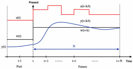
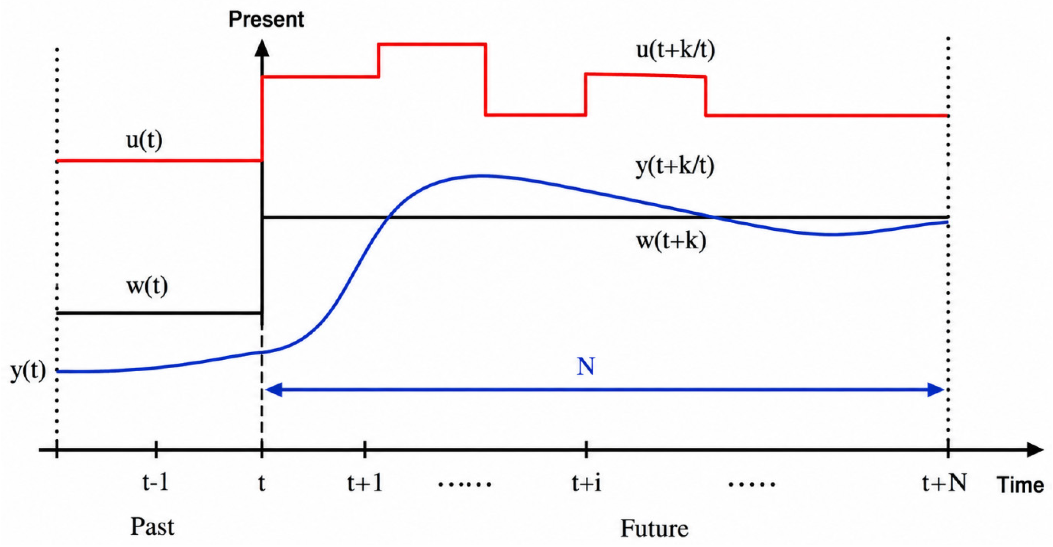
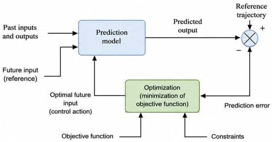
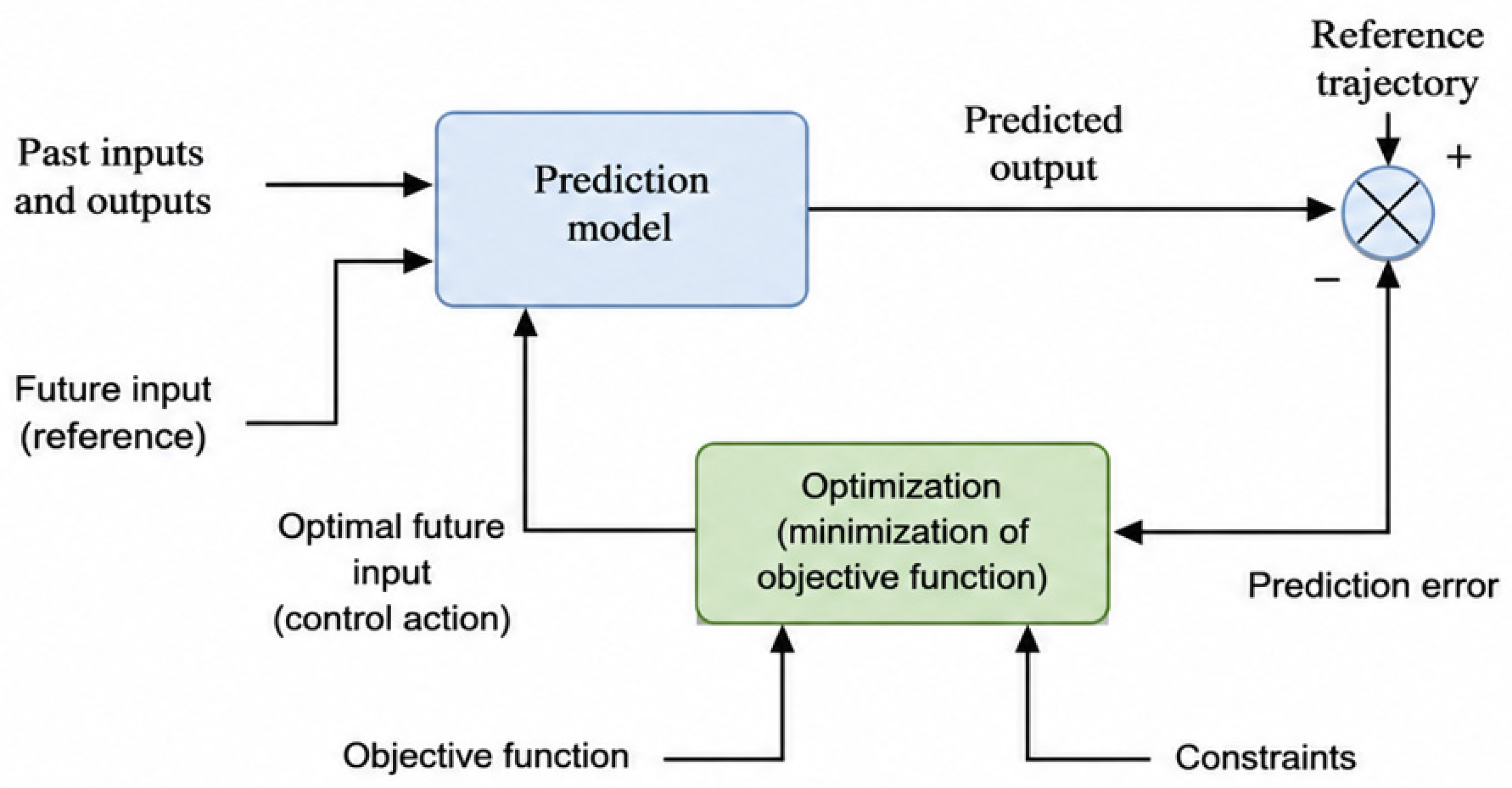
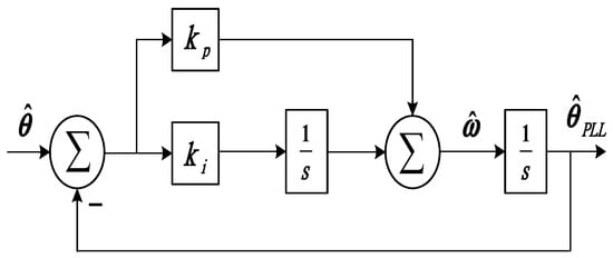
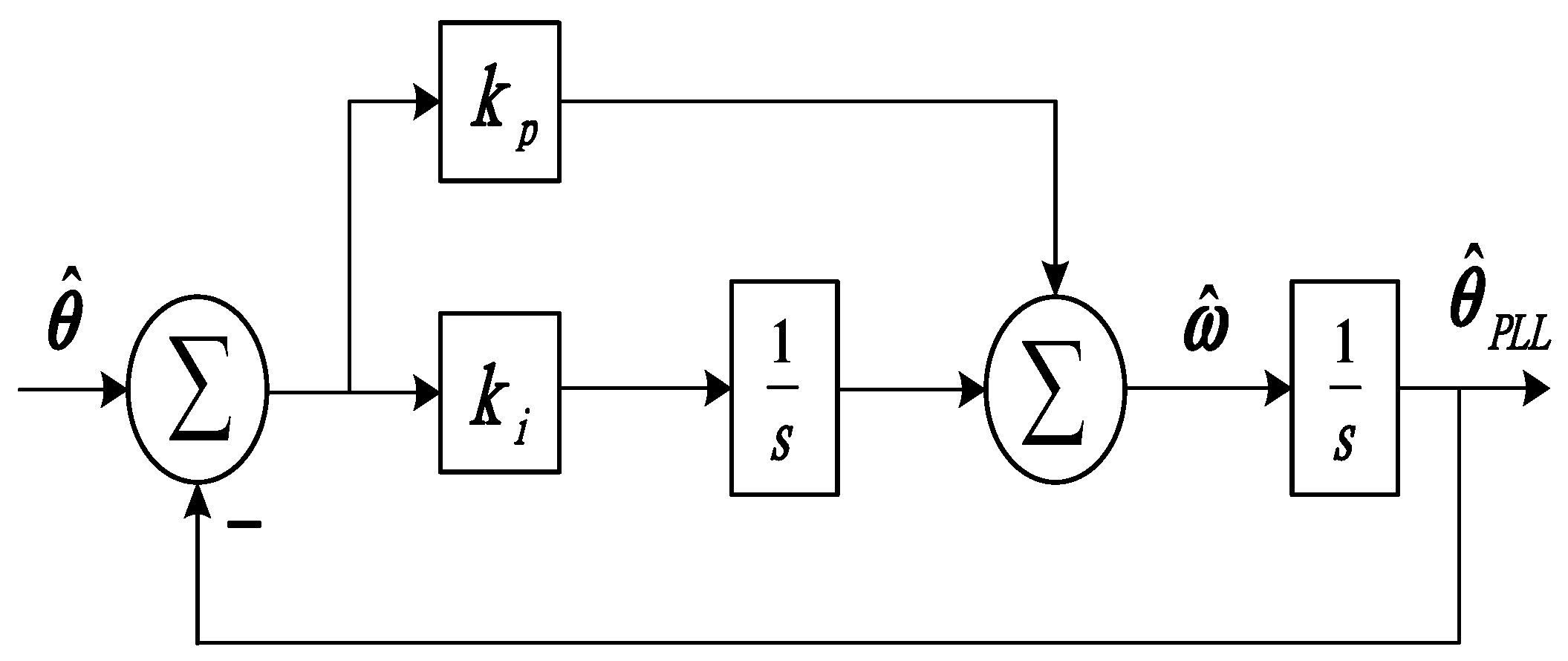
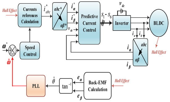
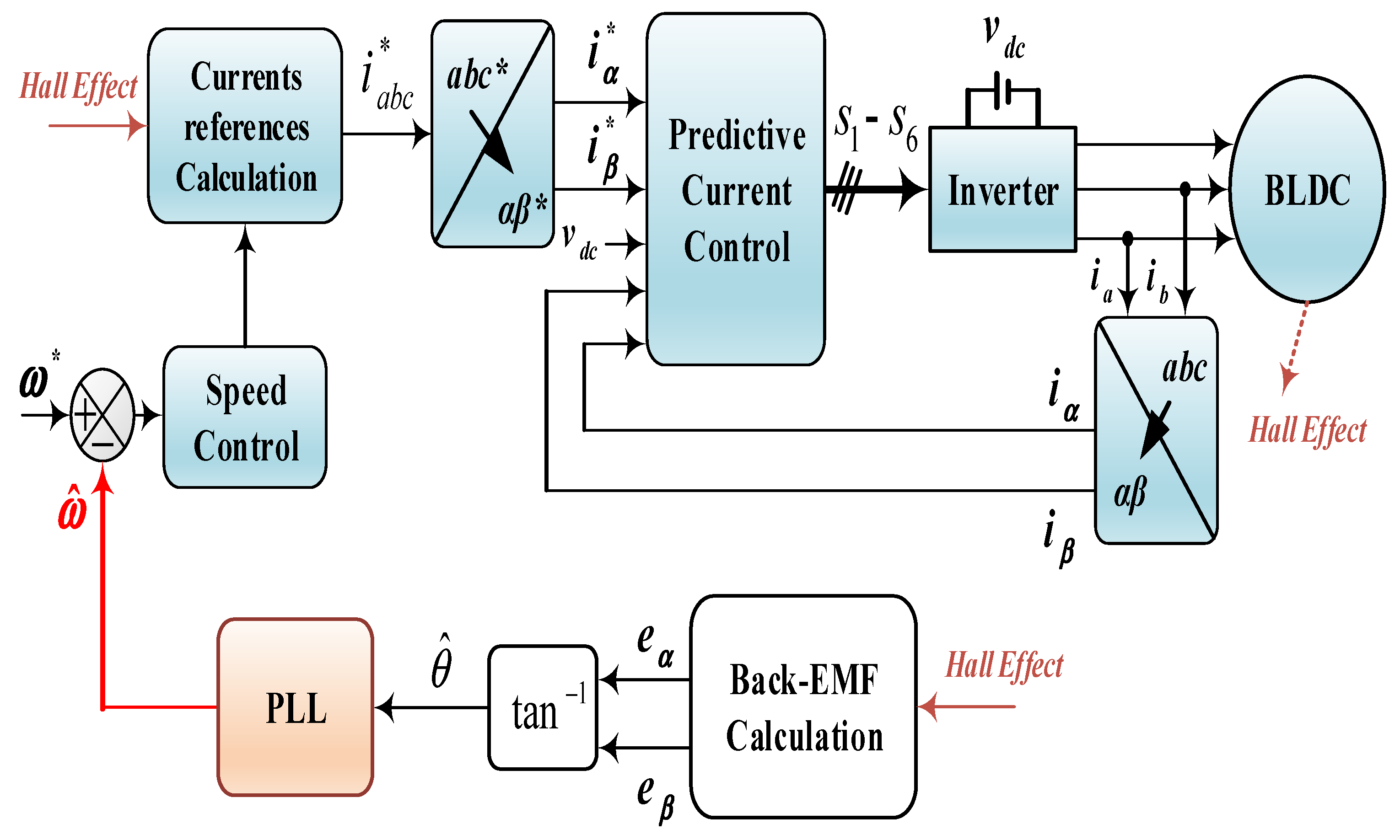
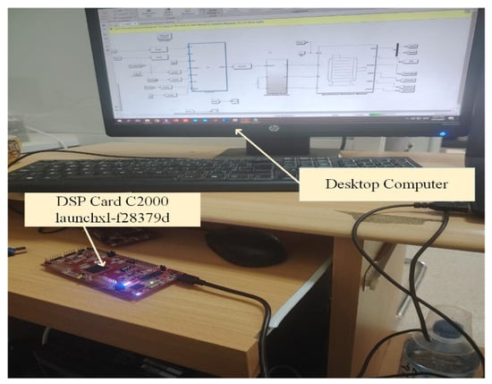
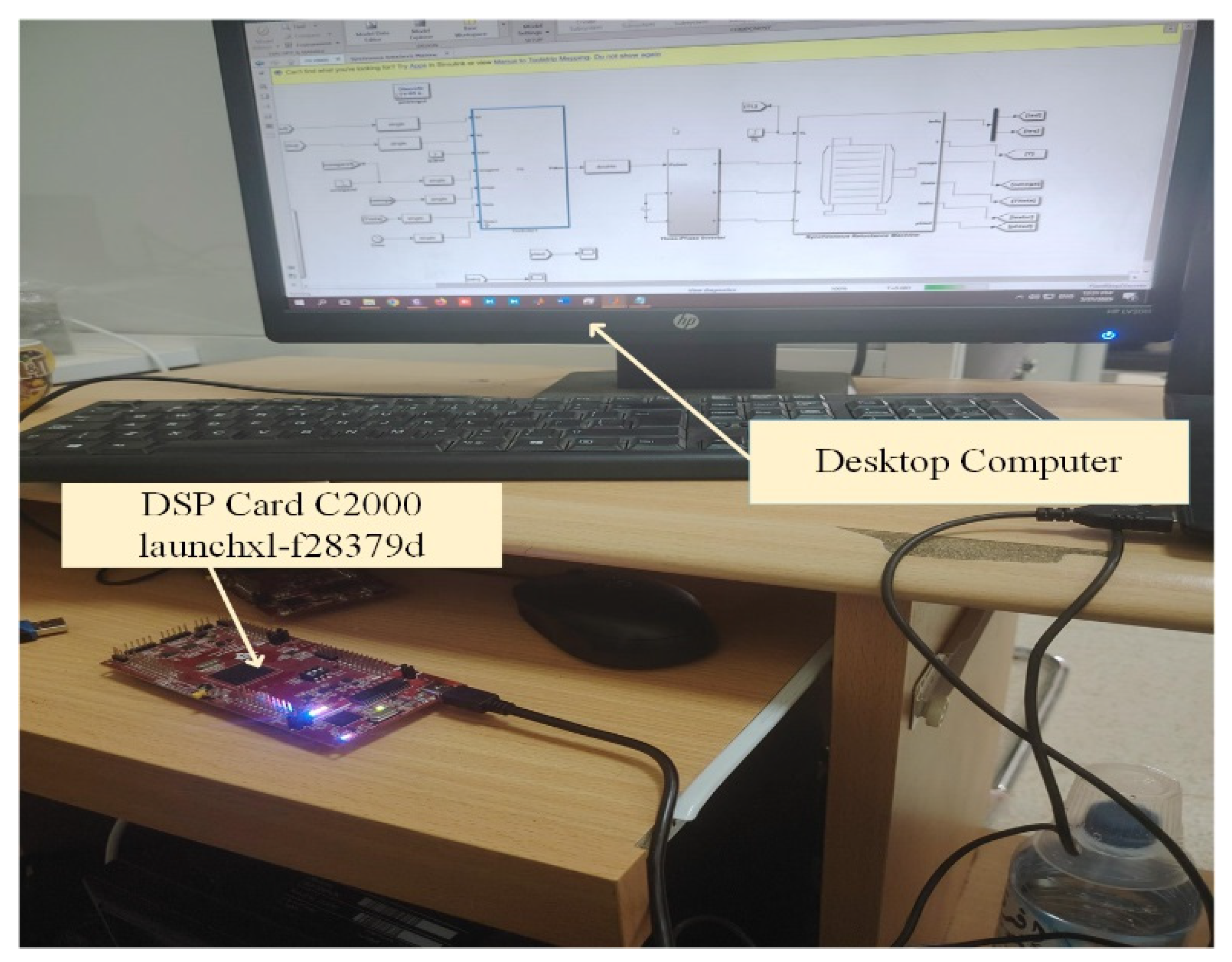
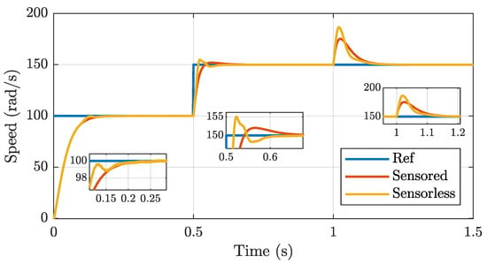
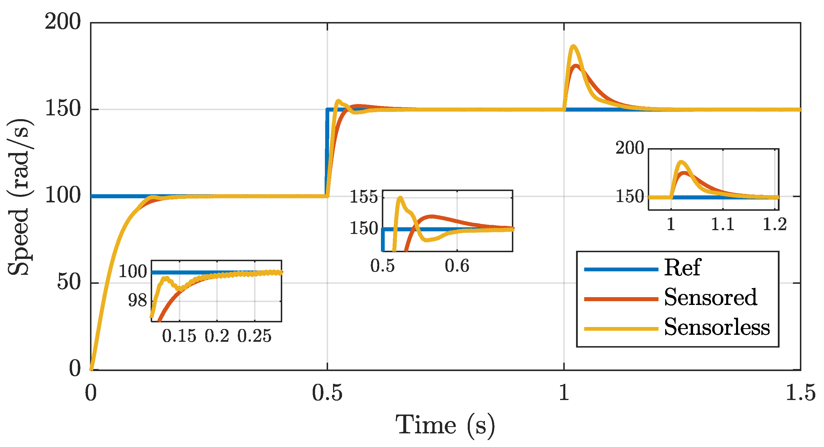
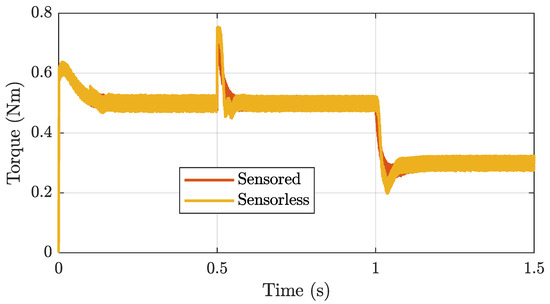
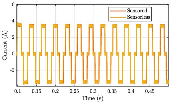
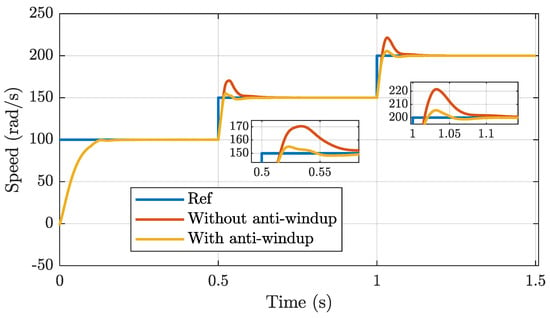
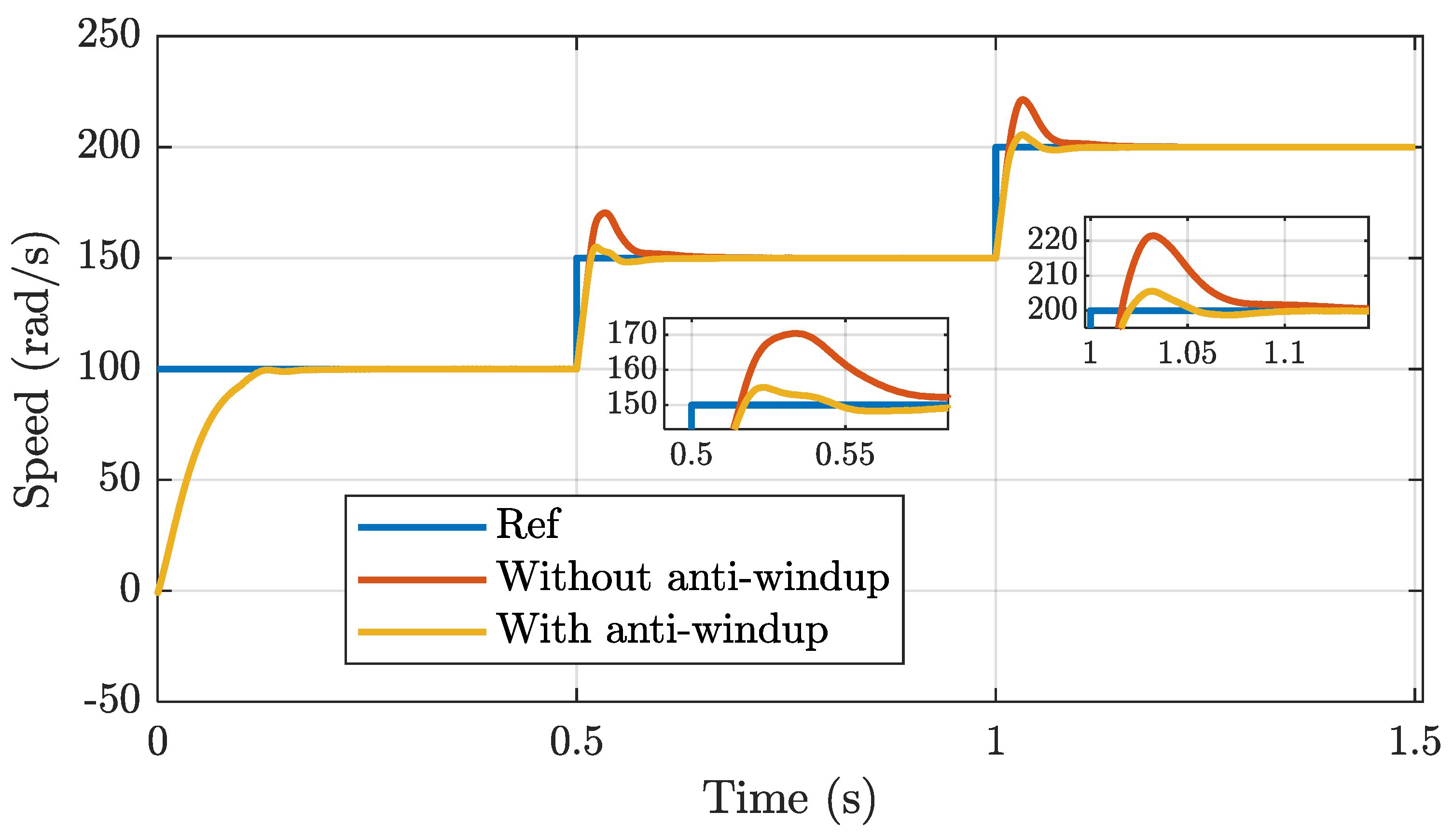
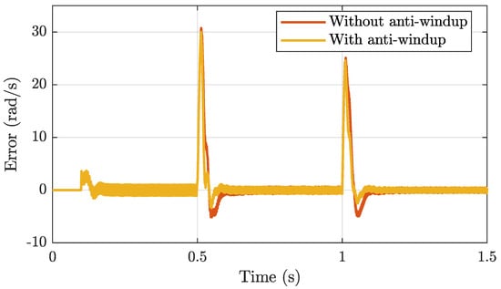
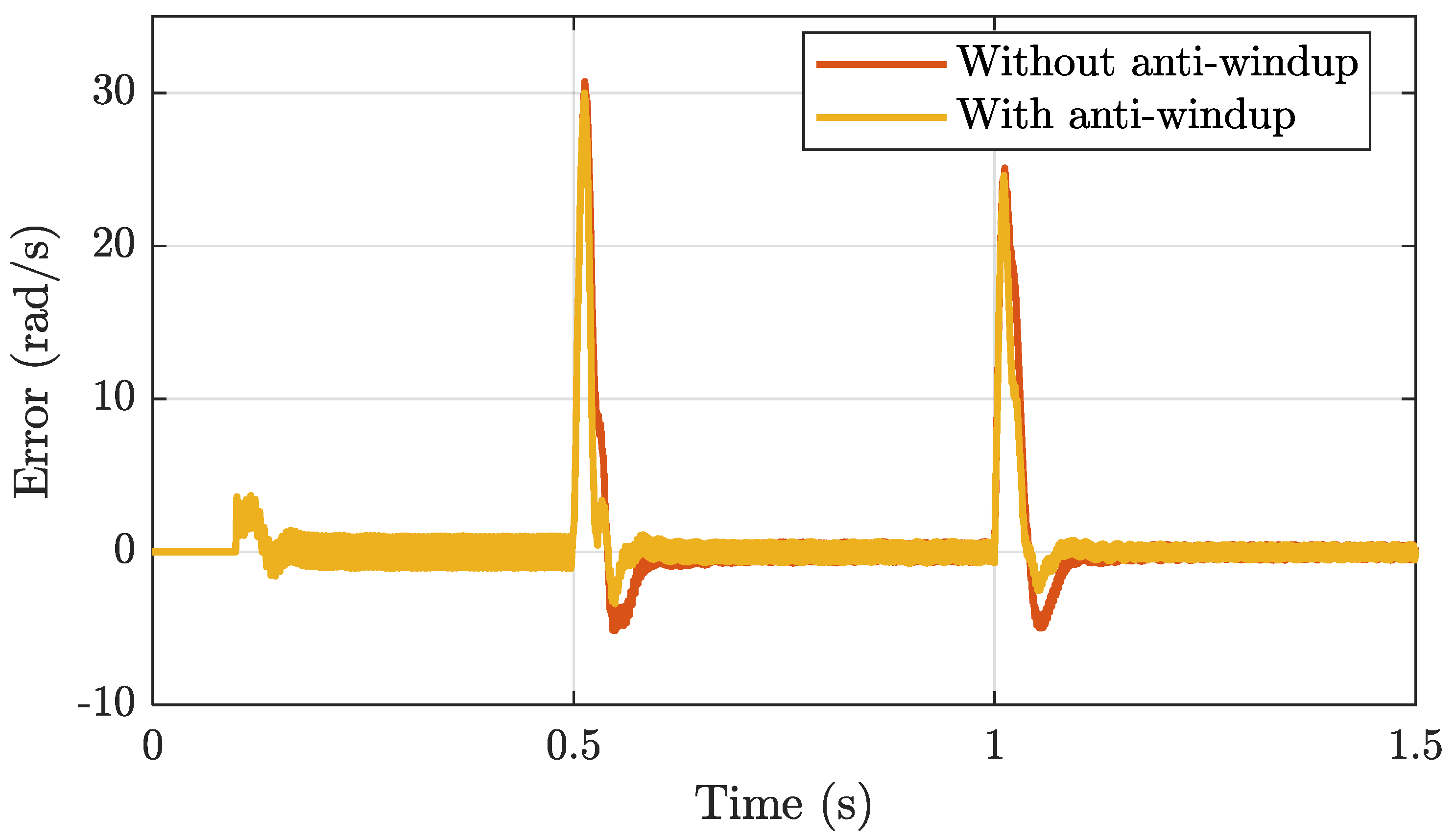
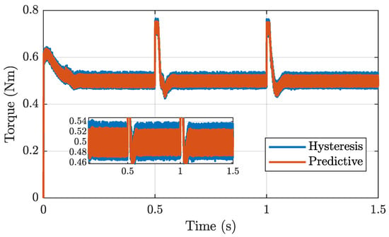
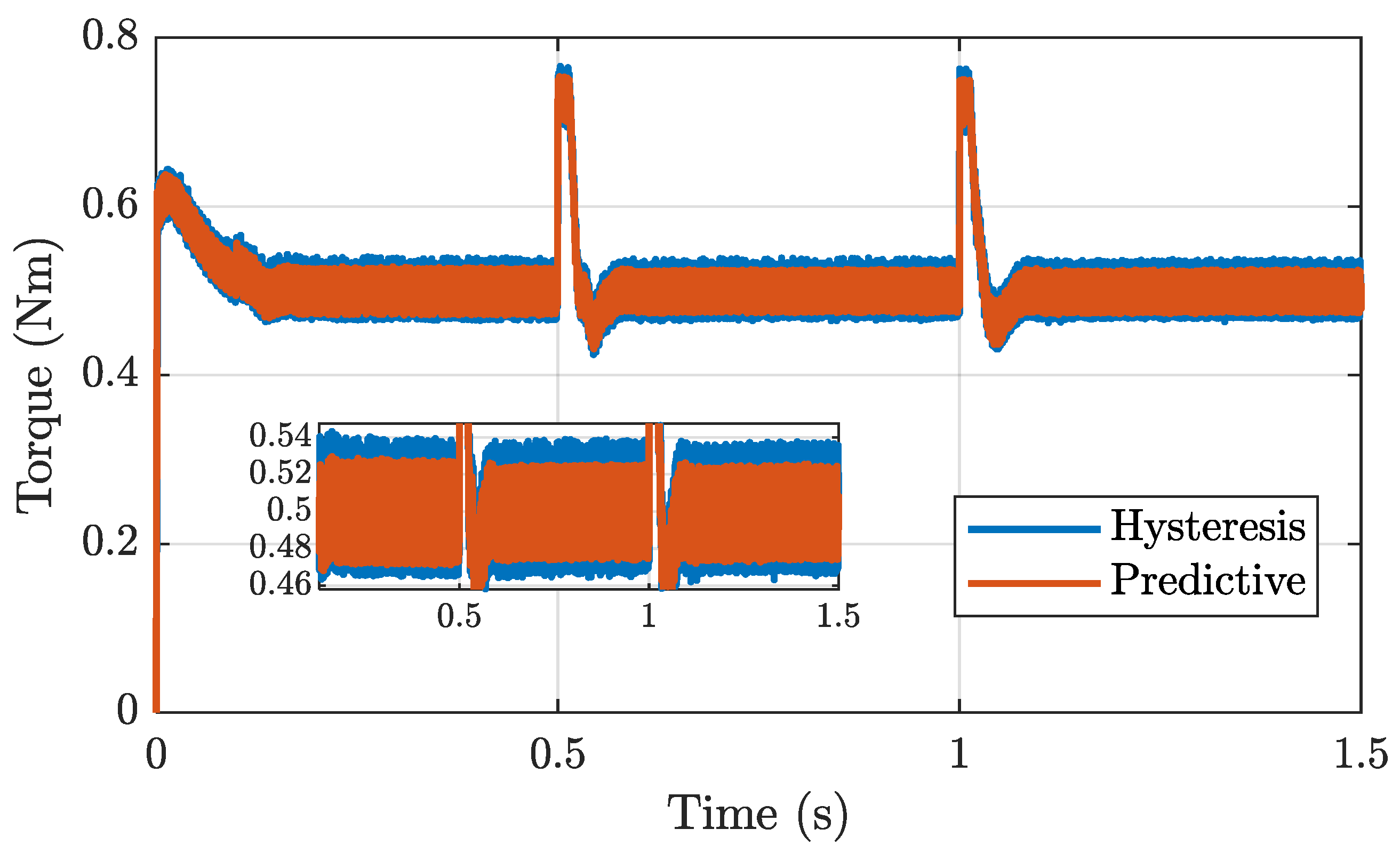

Disclaimer/Publisher’s Note: The statements, opinions and data contained in all publications are solely those of the individual author(s) and contributor(s) and not of MDPI and/or the editor(s). MDPI and/or the editor(s) disclaim responsibility for any injury to people or property resulting from any ideas, methods, instructions or products referred to in the content. |
© 2026 by the authors. Licensee MDPI, Basel, Switzerland. This article is an open access article distributed under the terms and conditions of the Creative Commons Attribution (CC BY) license.