


Abstract
Polyphase electrical motors exhibit a high degree of symmetry in both their mechanical configuration and electrical structure, which is reflected in analytical models, including dynamic and phasor-based representations. The aim of the present paper is to provide a short overview of polyphase electric motors, with a special emphasis on 12-phase permanent-magnet synchronous motors (12-phase PMSMs), from operating principles to application. While vector space decomposition and generalized Clarke–Park transforms have been documented for multiphase machines with five, six, and nine phases, the explicit derivation of these transformation matrices for the 12-phase case (arranged as four three-phase winding triads) is scattered across specialized sources or omitted altogether. This paper addresses that gap by deriving, in closed form, the complete set of transformation matrices (practical-to-fundamental, generalized Clarke, and generalized Park) for the 12-phase PMSM, and by consolidating them with the corresponding time-domain and Park-domain constitutive equations into a single self-contained tutorial reference. This article focuses on the analytic modeling of these motors using vector space decomposition (VSD), which allows for the differentiation of all odd-order harmonics. The Clarke and Park transforms are also employed, which simplifies the analysis of multiphase systems by reducing the number of equations to be dealt with and better managing the reference frame compared to a traditional Cartesian coordinate system. This paper is meant to deliver a short review of the subject matter focused on mathematical aspects as a contribution of tutorial value.
1. Introduction
The International Energy Agency (IEA) reports that electric motors are now widely used in various fields, ranging from household appliances to industrial applications. The IEA predicts that the use of electric motors in these sectors will continue to grow in the future, driven by the need to reduce carbon emissions and improve energy efficiency [1]. Since a large variety of electrical motors exist, the right choice depends on the application at hand and the available budget [2]. The vast majority of electrical motors fall into the categories of direct-current (DC) or alternate-current (AC) motors.
Compared to DC motors, AC motors do not require the use of switching parts (brushes and rotating collectors), which are the main causes of required maintenance, power loss, electric arcs, heat generation, and electromagnetic interference. DC motors were initially deemed more suitable for applications where it was necessary to accurately control speed [2]. The IEA has also recognized the benefits of AC motors and set standards to encourage their adoption [1]. These standards promote the use of energy-efficient AC motor systems, further driving the popularity of AC motors in various industries.
Asynchronous AC motors are characterized by an alternating current flowing through the stator windings to induce a current in the rotor winding, along with two magnetic fields. These magnetic fields operate at slightly different frequencies, and their interaction generates a mechanical torque on the rotor. In synchronous AC motors, the magnetic field permeating the rotor is due to either permanent magnets or to an excitation coil, and has constant direction in a reference system attached to the rotor. The rotor spins with an angular frequency synchronized with that of the magnetic field generated by the stator.
In the last two decades, the study and use of electric machines working on the basis of polyphase alternating currents has seen substantial growth, and this type of machine has re-emerged as a potential solution for various industrial applications. The use of three-phase electrical machines continues to be the main choice, but there is a tendency to reassess polyphase systems for certain applications, especially where the whole system is built from scratch or in applications where the risk of stator winding breakage is high. In fact, a noteworthy property of polyphase motors is that they can stay operational even in the event of one or more three-phase breakdown [3].
In particular, unlike in a three-phase drive, the loss of stator phase does not prevent the machine from starting and running. Other advantages of multi-phase systems include increased torque per ampere for the same volume machine, reduced stator copper losses, and reduced rotor harmonic currents [4]. Criticisms of higher-phase motors is due to their more complex inverter control scheme and higher cost [5]. The main application areas of multiphase induction motor drives are ship propulsion, traction (including electric and hybrid electric vehicles), and the concept of “more-electric” aircraft. Other suitable applications are locomotive traction, aerospace, and high-power applications [4].
Research specifically targeting 12-phase machines remains comparatively limited. Existing studies on this configuration have largely concentrated on fault-tolerant control design, for instance the reconfiguration strategies for open-circuit and inverter-leg faults discussed in [3], rather than on providing a consolidated and self-contained derivation of the underlying analytical model. As a result, a reader approaching 12-phase PMSMs must typically reconstruct the transformation framework by combining generalized n-phase treatments, as in [6,7], with machine-specific fragments drawn from control-oriented papers, since no single accessible source walks through the full derivation from the practical winding configuration to the final dq0 model for this specific phase count. This dispersion of the mathematical background across sources motivates the tutorial-style treatment adopted in this paper.
This manuscript aims at presenting a literature review of the analytical modeling of 12-phase permanent-magnet synchronous motors, aiming to provide both theoretical insights and potential applications. The topic is timely and relevant considering the growing interest in multiphase machines due to their enhanced reliability, fault tolerance, reduced losses, and control flexibility. This paper covers essential concepts such as vector space decomposition, the generalized Clarke and Park transformations, and modeling in the Park domain. It attempts to offer a synthesis to help readers understand the fundamental principles and mathematical tools associated with multiphase motor systems.
Existing reviews on multiphase machines tend to either address the general n-phase case at a high level of abstraction or focus on specific low-phase-count configurations (five- and six-phase machines being the most extensively documented in the literature), leaving the 12-phase configuration comparatively underrepresented despite its practical relevance in high-power and fault-critical applications such as ship propulsion and more-electric aircraft. The specific contribution of this paper is to close this gap by explicitly deriving the full chain of transformation matrices, from the practical reference frame to the fundamental Clarke () and Park (dq0) domains, for the 12-phase case arranged as four three-phase winding triads, as well as by presenting the corresponding time-domain and Park-domain constitutive equations (voltage, flux linkage, and torque) in a unified and internally consistent notation. The main contributions of this paper can be summarized as follows:
- An explicit step-by-step derivation of the transformation chain, including practical, fundamental, Clarke (), and Park (dq0) reference frames, for a 12-phase PMSM composed of four three-phase winding triads (Section 6).
- A complete time-domain and Park-domain mathematical model of the 12-phase PMSM, including the stator voltage, flux linkage, and torque equations, consolidated within a single consistent notation (Section 7).
- A discussion of open modeling challenges and directions for future work specific to 12-phase machines (Section 8).
The manuscript is deliberately hybrid, blending critical review content with pedagogical clarity to benefit both researchers and engineers. The tutorial-like approach to complex mathematical tools (VSD, Clarke–Park transforms) is intentional, aligning with the journal’s emphasis on accessibility without sacrificing scientific rigor. The objective is to synthesize modeling techniques for 12-phase PMSMs, offering both theoretical insight and practical background. For this reason, we deliberately prioritize seminal and foundational works essential to understanding the mathematical framework.
Outline of the short review. Section 2 describes the general characteristics of polyphase electric machines and their advantages over a three-phase machine. Synchronous permanent-magnet motors are then reviewed in Section 3 along with their operation and advantages over asynchronous motors. Section 4 presents a short review of noteworthy applications of polyphase motors. Section 5 turns specifically to the 12-phase configuration considered in this paper, summarizing its winding structure, inverter topology, control strategies, fault modes, and industrial applications, followed by a more detailed mathematical treatment. Section 6 carries on the detailed description of the theoretical concepts necessary to formulate and manipulate the equations that appear in the polyphase motor mathematical model. In particular, a technique called vector space decomposition (VSD) is recalled that allows for the modeling and management of most polyphase electric machines through the generalized transforms of Clarke and Park. Section 7 then applies this mathematical toolkit specifically to the 12-phase PMSM, deriving the complete time-domain and Park-domain model. Finally, Section 8 concludes the paper and outlines directions for future work. Figure 1 summarizes the content of the main sections.
Figure 1.
Structure of the paper. Section 2, Section 3 and Section 4 provide background review material; Section 5 bridges this background to the specific 12-phase case; Section 6 and Section 7 (highlighted) form the tutorial core, first developing the general mathematical toolkit and then applying it to the specific 12-phase PMSM case.
2. Features and Advantages of Polyphase Electric Motors
An electric machine is called polyphase if the number of phases n of the stator is larger than three. A motor of this kind is usually obtained by redesigning the stator frame or simply by rewinding the stator of a three-phase machine to obtain n independent windings accessible by terminals. In a polyphase electric drive, electromechanical energy conversion is achieved by using a polyphase machine that is powered by a polyphase converter through a particular control strategy. The deployed control action must in particular take into account additional degrees of freedom which are unique to polyphase systems, allowing for unconventional modes of operation. This manuscript offers a focused and technically sound review of 12-phase PMSMs supported by rigorous mathematical modeling, a synthesis of the analytical tools crucial for understanding and controlling polyphase machines, integration with the literature, and practical relevance to applications in transportation, aerospace, and industry.
Below are listed a few potential advantages of polyphase electric machines (MPMs) that can justify their increased complexity.
- Reduction of phase currents at constant power and voltage [8]. The first advantage of MPMs is the ability to lower the rated current per phase while maintaining the same voltage and rated power as a conventional three-phase machine. The active power P in an n-phase balanced system is expressed aswhere U denotes the peak voltage, I denotes the peak current, and denotes the power factor. By maintaining the same values of power supply P and voltage supply U with an approximately constant power factor, it is immediately apparent that lower values of supply current I can be obtained by increasing the number of phases n. This phenomenon can be advantageous in high-power applications where the voltage U is kept constant and less powerful converters can be used in terms of maximum output current, thereby reducing the overall system cost.
- Reduction of stator energy loss [8]. The distribution of the magnetomotive force (MMF) along the air gap, interacting with the temporal harmonics introduced by the sinusoidal or non-sinusoidal input voltages at the machine terminals, generates spatial harmonics that affect the geometric distribution of the magnetic flow, which in turn influences the mechanical torque. As summarized in [8], an increase in the number of phases causes a displacement of spatial harmonics (besides the fundamental one) induced by excitation of the fundamental frequency towards the higher frequencies, making the MMF smoother and ripple-free. However, the same study showed that low-order spatial harmonics may be generated for other temporal harmonics in the excitation depending on the value of n. From the point of view of stator energy loss, a five-phase machine could theoretically achieve % less power loss than its three-phase counterpart. This reduction, however, does not make for a dramatic improvement, since a hypothetical machine with an infinite number of phases would bring loss reduction to %. In general, there is some potential for loss reduction; however, overall efficiency depends heavily on geometric design (not considered in this discussion) and control strategy.
- Mitigation of torque pulsation [8]. In general terms, torque pulsation arises from the interaction between field components generated by windings having the same number of pole pairs p which rotate at different speeds. The pulsation frequency depends on the difference between these speeds. Torque pulsations of larger magnitude are those that occur when the -poles main field is involved. The temporal harmonic components of the excitation that can generate a -poles field are of orderSpecifically, the -order temporal harmonic generates a -pole field that rotates in the same direction as the main field but times faster, whereas the -order temporal harmonic generates a -pole field that rotates backwards and times faster compared to the main field. In both cases, the pulsation frequency of the resulting torque in [8] is given bywhere denotes the pulsation frequency of the fundamental excitation (and hence of the main magnetic field). A higher number of phases increases the frequency of the torque pulsation. Equation (2) can be used to determine which harmonics are potentially troublesome and should be avoided; for example, for a nine-phase machine, the excitation harmonics to be avoided are of the order (17a, 19a, 35a, 37a, and so forth). In fact, the relation in (3) shows that in the presence of such excitation, torque pulsations 18 and 36 times faster than the main excitation frequency would appear. These results were obtained by assuming a smooth air gap surface on both the stator and rotor [8]. The effect of stator and rotor notching is to perturb the harmonic fields; therefore, it is very difficult to make general statements about the relative merits of multiphase machines. The relation in (3) indicates that torque pulsations appear at higher frequencies if polyphase models are chosen.
- Improved fault management [3]. An n-phase machine can continue to operate as long as no more than phases have failed. In other words, as long as three phases are supplied, a rotating magnetic field can be produced, although with reduced mechanical power/torque. The amount of power and torque that can be produced depends on the type of fault as well as on the geometrical and mechanical design of the machine. For example, a six-phase electrical machine built with a split-phase configuration (two sets of three-phase windings spatially shifted by 30 electrical degrees) will have different fault handling possibilities depending on whether or not the star point is isolated between the two sets of windings [3]. In case of an isolated star point, the strategy in the event of a phase loss is to remove a complete set of three-phase windings (including the one containing the failed phase), reducing the machine rating by 50%. Several possibilities are available with a common star-center connection, where the shape of the current can be changed to maintain a rotating magnetic field (although introducing some asymmetry in the currents). Error tolerance strategies include:
- -
- Maintaining the same current intensity in the remaining phases in the event of a phase failure, which reduces stator energy loss by a factor of approximately .
- -
- Increasing the current intensity in the healthy phases by a factor , which maintains about the same energy loss.
- -
- Increasing the current intensity in the healthy phases by a factor , which increases stator energy loss while maintaining the same level of torque [9].
While the discussion above illustrates the theoretical fault margin of polyphase machines, a more critical assessment must distinguish between the different fault types that can occur in practice, since each imposes distinct constraints on the machine and its control system. Open-circuit faults, in which a stator phase or an inverter leg stops conducting, are the most commonly addressed case in the literature and are the primary scenario considered in the fault-tolerant control strategies discussed in Section 4.1 [10,11,12,13]. By contrast, short-circuit faults are considerably more severe: an inter-turn or phase-to-phase short circuit can drive large circulating currents even when the affected phase is electrically isolated from the healthy ones, and containing this fault typically requires either a physical disconnection device or a redundant winding design capable of limiting the short-circuit current by construction rather than a control-level reconfiguration alone. Inverter-leg faults occupy an intermediate position: depending on the converter topology, a failed leg may be reconfigurable at the switching level, as demonstrated for a five-level cascaded H-bridge converter in [10], or may require the same corrective action as a full open-circuit phase loss. Therefore, a rigorous treatment of fault tolerance in a 12-phase PMSM should specify not only the number of phases that can be lost, as in the criterion recalled in this section, but also which fault type is assumed, since the achievable post-fault performance and the required protection hardware differ substantially between these cases. - Augmented degrees of freedom. Since only two currents are needed to control average flux or average torque irrespective of the number of phases, the remaining degrees of freedom can be exploited for other purposes, including:
- -
- Increased torque density: In conventional three-phase machines, the presence of space harmonics usually causes only unwanted currents and torque ripple. In polyphase machines, however, space harmonics can be used to generate average torque, increasing the torque density of some specific designs [9]. This is usually achieved by injecting some precise time harmonics into the current in machines with concentrated windings. This phenomenon is best appreciated in symmetrical odd-phase machines. A minimum gain of at least 10% over conventional three-phase motors appears to be achieved with five-phase machines with injection of the third harmonic into the stator currents [9]. However, this causes the presence of harmonics in the air gap flux, increasing the flux density and consequently the iron losses.
- -
- Improved multimotor driving: Multiple polyphase machines with sinusoidal MMF distribution can be controlled independently in series with a single electronic feeder [9]. This result is achieved by appropriate transposition in the connection of machine phases, so that the components that triggers flux/torque in one machine appear as currents that do not produce flux/torque in all other machines.
- Advantages for developers [8,14]. The use of a higher phase number offers an inverter designer the opportunity to make use of standardized power modules of fixed VA rating without necessarily having to resort to series or parallel stacking. The power may be delivered to the motor through as many of these standard modules as is necessary to make up the required total rating. For the motor designer, the advantages of multiple phases are that the magnetomotive force (MMF) waveform can be improved, the line voltage can be reduced, and efficiency can be increased.
A breakdown of the advantages and disadvantages of polyphase electrical motors is presented in Table 1. It should be stressed that the extent to which these advantages materialize in practice is not determined by the phase number alone but jointly by the winding configuration, inverter topology, and adopted control strategy. The loss reduction figures, torque ripple mitigation, and fault tolerance margins reported above and summarized in Table 1 correspond to specific machine designs and operating conditions studied in the cited literature, and should not be interpreted as guaranteed or invariant properties of polyphase machines in general.
Table 1.
Advantages and disadvantages of polyphase electric motors.
In the specific case of the 12-phase PMSM considered in this paper, the general fault tolerance principle discussed above takes on particular significance. Since the winding is arranged as four independent three-phase triads spaced 15 electrical degrees apart, the loss of an entire triad, for instance due to an inverter-leg fault, still leaves three three-phase sets operational, meaning that in principle the machine can sustain failure of up to nine of its twelve phases (, with ) before losing the ability to produce a rotating magnetic field. This redundancy margin is substantially larger than what is achievable with five- or six-phase machines, and is one of the main motivations for adopting 12-phase PMSMs in safety-critical applications such as more-electric aircraft actuation and ship propulsion. In practice, however, the fault tolerance that is actually achieved depends on further factors, including whether the neutral points of the four triads are isolated or interconnected, the specific nature of the fault (open-circuit or short-circuit, phase-level, or inverter leg-level), and the reconfiguration strategy applied to the healthy phases, as discussed for the 12-phase case in [3].
The advantages of increasing the phase number that are discussed above can be made more concrete by comparing specific phase counts directly. Table 2 reports such a comparison for , and 12 phases, distinguishing between quantities that can be derived directly from the relations already presented in this paper, namely, the current-reduction relation and the fault tolerance criterion, and quantities that are only reported in the reviewed literature for specific phase counts. This distinction is made explicit in the table caption, since a systematic quantitative comparison covering efficiency, torque density, and cost across all five phase counts is not, to the authors’ knowledge, available in a single source in the existing literature; most comparative studies report detailed performance figures for one or two specific phase counts (most commonly five- or six-phase machines) rather than providing a comparison spanning the full range considered here. Where a quantitative figure specific to a given phase count could not be located in the sources reviewed for this paper, the corresponding table entry is marked as not available (n/a) rather than being estimated, so as not to overstate the precision of the comparison. The converter complexity and relative cost rows are included as qualitative trend indicators only, reflecting the general consensus of the reviewed literature that both quantities increase with phase count due to the larger number of semiconductor switches, gate drivers, and current sensors required rather than as measured or simulated figures.
Table 2.
Quantitative and qualitative comparison of polyphase machines with phases. Values marked with ∗ are derived directly from Equation (2) or from the fault tolerance criterion; values marked with † are reported in the cited source for the specific phase count indicated, and are not available in the reviewed literature for the other phase counts; values marked with ‡ are given as a range because the number of orthogonal harmonic subspaces depends on the winding configuration (symmetric versus asymmetric/split-phase arrangement), as discussed in Section 6.1; entries marked “n/a” indicate that no quantitative value specific to that phase count was found in the sources reviewed in this paper. Qualitative trend columns (converter complexity, relative cost) reflect the general consensus of the reviewed literature rather than measured figures.
3. Permanent-Magnet Synchronous Motors (PMSMs)
In the past, synchronous motors were considered constant-speed motors with axial rotation speed (the synchronous speed) dependent on the power supply frequency and number of pole pairs. For this reason, synchronous motors were considered unsuitable for variable-speed electric drives, and their application was limited to those areas where speed and/or position control was not of main concern [9].
Electrical synchronous machines found wide use as energy generators rather than as motors. Even today, almost all alternating-current electric generators are synchronous, and the vast majority of the electrical power engaged in power plants is generated by synchronous machines [24]. Interest in the permanent-magnet synchronous motor has been steadily growing in recent years because of its many advantages over other machines of both of DC and AC type that are conventionally used in drives [9].
Conventional synchronous machines require a continuous power supply to the rotor field winding, which is provided by a system of brushes and rings. Such rotating contact structures are the main cause of energy and require continual maintenance. The use of permanent magnets to replace the field winding, DC power supply, and collector elements eliminates all such disadvantages. From this observation, the permanent-magnet synchronous motor (PMSM) was born. Also called ‘sinusoidal brushless’ motors, PMSMs are a type of AC synchronous motor that exhibits construction and operating characteristics quite similar to classical synchronous motors except that the rotor carries no field windings. Instead, the rotor embodies permanent magnets that are used to create field poles and generate the rotor static magnetic field. Since there is no need for a DC source supply, these types of motors are simpler to build and prove to be cost effective.
The structure of a permanent-magnet synchronous motor consists of a rotor in which the permanent magnets are placed and a stator that accommodates a number of windings tasked with generating the rotating magnetic field. These windings are powered by sinusoidal currents synchronized with the corresponding concatenated fluxes due to the magnet. At synchronous speed, the rotor magnetic poles concatenate with the rotating magnetic field generated by the stator.
The electromechanical conversion implemented by the motor follows the principle of operation of electrodynamic systems, which is based on the interaction between the current-carrying conductors in the stator and the magnetic fields created by the permanent magnets in the rotor.
The working principle of a permanent-magnet synchronous motor is similar to that of a classical synchronous motor. It depends on a stator rotating magnetic field that generates electromotive force at synchronous speed together with a constant magnetic field of the rotor. This field is generated by the permanent magnets inside the rotor, which create a constant magnetic flux. When the stator windings are excited by supplying polyphase AC power, a rotating magnetic field arises within the air gap.
In this way, a mechanical torque of some amplitude is generated when the rotor field concatenates with the stator rotating magnetic field, causing the rotor to spin at a constant (synchronous) speed . The operation of starting a synchronous motor is complex because it has an impulsive torque characteristic centered on the speed . In other words, the rotor receives driving torque only and exclusively if it is spinning at a speed . When the motor axis is still, application of the stator supply voltage cannot trigger motion because the rotor receives zero torque, as shown in Figure 2.
Figure 2.
Mechanical torque T versus axis rotation speed in a permanent-magnet synchronous motor. The torque in this kind of motor exhibits a single spike at a speed .
Since permanent-magnet synchronous motors are not automatic-start motors, some PMSMs incorporate an additional ‘squirrel cage’ rotor that embodies asynchronous behavior, and switch to synchronous mode only once starting has occurred. These are known as line-start or self-starting PMSMs. They are used as more efficient replacements for asynchronous motors due to their lack of slip, and must be designed to ensure that synchronous speed is achieved. In addition, the stator may be endowed with a variable-frequency power supply; this is electronically controlled, for example via an inverter. Varying the frequency of the power supplied to the stator windings in a controlled way causes the generation of a rotating magnetic field that initially spins at low speed, allowing the constant magnetic field generated by the permanent magnets in the rotor to concatenate with the former. In this, way the rotor begins to rotate at the same speed as the rotating field. By increasing the power supply frequency, the speed of the rotating magnetic field increases, and as a result the rotor also increases its rotation speed to maintain synchronization.
The rotor, home to the permanent magnets, can be made in different configurations. The waveform of induction within the air gap is closely related to the shape of the magnets. The arrangement and type of magnets also affects the level of mechanical power and torque that can be developed along with the operating characteristics of a PMSM, and strongly influences the overall cost of the motor. Inexpensive ferrites, AlNiCo alloys, or materials embodying rare earth elements such as samarium cobalt (SmCo) and neodymium iron boron (NdFeB) can be used as permanent magnets [25].
In particular, neodymium (NdFeB) magnets have been the most commonly used magnets in PMSMs due to the high value of their coercive field and residual induction, which make them difficult to demagnetize. However, because of fluctuating prices the use of ferrite magnets is preferred nowadays, although new machines using these types of magnets have lower power density and torque density than machines based on neodymium magnets [25]. Permanent magnets in general (with the exception of AlNiCo alloys) present the problem of brittleness and poor machinability, which limits manufacturers in making complex shapes and pushes them to fine-tune the arrangement of the magnets rather than their shape.
In radial flux configurations, the simplest arrangement consists of magnets external to the rotor surface. Attachment of the magnets to the rotor is usually done by bonding through special resins; to improve strength, the union between two parts is often completed with an external carbon fiber ring. Fastening is easier in the case where the magnets are internal superficial. When magnets are drowned in iron, the problem of fastening does not arise at all.
Whenever the magnets are placed internally, the mechanical structure of the rotor appears to be more robust, which makes such designs particularly suitable for high-speed applications, as the magnets are physically contained within the rotor and hence protected. On the other hand, in this configuration there is more dispersed flux, which produces magnetic induction in the lower air gap and consequent increase of losses. To mitigate such problems, one can resort to the interposition of nonmagnetic separators; however, this complicates the realization of the rotor, as the laminations are no longer a single piece with grooves for the magnets but instead consist of several pieces that must be assembled. Alternatively, a tangential magnetization of the magnets can be used in which facing homonymous polarities are used to preserve the radiality of the flux while also reinforcing the induction at the air gap.
Permanent-magnet synchronous motors are characterized by a higher torque/inertia ratio and better dynamic response due to the presence of the permanent magnet instead of a winding in the rotor that increases the density of magnetic flow in the air gap. PMSMs are also more efficient and easier to cool down, as losses related to rotor currents are greatly reduced. In addition, their power/weight ratio is higher than that of induction motors, and no creep rate calculation is required in the control strategy [9].
The disadvantages of these motors include the variation of their properties over time and temperature changes. For proper operation, PMSMs need high-resolution position sensors along with a power inverter and a microprocessor for managing all of the necessary components [8]. Another limitation that this kind of motor incurs is excessive cost for high-power applications. If the power of the motor is relatively large, the cost of the permanent magnets increases significantly. Materials for permanent magnets such as samarium cobalt can be quite rare and expensive [25]. However, while cost is a factor to consider, it but does not necessarily compromise the feasibility of these motors. At present, the highest-power high-speed induction machine is a 15 MW and 20,000 RPM machine developed by ABB [26].
The previously highlighted features make these motors suitable in several applications, including as actuators in robotics and aerospace, electric vehicles, paper making, packaging, textiles, ceramics, glass, and woodworking.
The main characteristics of PMSMs can be summarized as follows:
- High flux density at the air gap
- High power/weight ratio
- Wide torque/inertia ratio, which guarantees high acceleration
- Small torque oscillations even at very low speeds, which allows for considerable accuracy in positioning
- Wide range of speed variation
- Possibility of operation at high torques, which allows for rapid acceleration and deceleration
- High efficiency and high power factor
- Geometrically compact structure.
The development of new technologies and materials for the production of permanent magnets with excellent magnetic characteristics has greatly contributed to the success of PMSMs in the field of variable-speed electric drives.
A breakdown of the advantages and disadvantages of permanent-magnet synchronous motors is presented in Table 3.
Table 3.
Advantages and disadvantages of permanent magnet synchronous motors.
4. Recent Literature Review and Industrial Applications of Polyphase Electrical Motors
4.1. Recent Literature Review
Liu et al. presented an innovative design approach for multi-phase PMSMs with fractional-slot windings aimed at mitigating electromagnetic vibrations, a critical concern in high-performance electrical machines [27]. They introduced a combined analytical and simulation-based methodology that incorporates stator teeth modulation effects into the electromagnetic design process. Their results demonstrate that appropriate winding and slot configurations can significantly reduce vibration-induced acoustic noise without sacrificing power density or efficiency, making the findings highly relevant for PMSMs deployed in applications with strict noise and vibration constraints, such as electric vehicles and aerospace systems.
Gao et al. addressed the control challenges of six-phase PMSMs, with a particular focus on eliminating position sensors to reduce system complexity and cost [28]. Their paper proposed an improved sensorless control strategy that enhances rotor position estimation accuracy under varying load and speed conditions. Utilizing advanced back-EMF estimation techniques and adaptive filtering, they were able to achieve reliable position detection, enabling efficient and fault-tolerant operation of six-phase PMSMs. The results underline the advantages of multiphase architectures for critical drive applications, highlighting improvements in redundancy and system robustness.
The special issue in [29] compiles state-of-the-art research on dual three-phase PMSMs, covering both advanced machine design and control techniques. The included works present fault-tolerant control methodologies, enhanced modeling approaches for machines with high power density, and experimental validations of multi-phase drive systems. The issue emphasizes the growing industrial relevance of multiphase machines, particularly for applications in transport electrification and renewable energy where high fault tolerance and power quality are essential. It also identifies ongoing research challenges, providing a comprehensive overview of current technological progress in polyphase motor systems.
Sahu et al. investigated the modeling and performance analysis of five-phase surface-mounted PMSMs designed for electric vehicle traction applications [30]. They developed a detailed dynamic model incorporating both electrical and mechanical subsystems and assessed performance indicators such as torque output, efficiency, and response to fault scenarios. Their findings confirmed that five-phase PMSMs offer superior fault tolerance, smoother torque production, and improved operational reliability compared to conventional three-phase machines, reinforcing their suitability for high-demand EV applications.
The conference contribution in [31] presents further validation of five-phase PMSMs for electric vehicle powertrains, emphasizing both design methodology and control aspects. Through simulation-based performance assessments under various operating conditions including transient loads and partial faults, this study demonstrates that five-phase machines exhibit enhanced reliability, fault tolerance, and harmonic performance. These characteristics make them strong candidates for next-generation EV systems where safety, efficiency, and robustness are paramount.
Shayeghan et al. [10] presented a robust fault-tolerant control strategy for six-phase PMSMs using hardware-in-the-loop (HIL) testing and vector space decomposition. Their method uniquely integrates real-time fault detection, open-circuit fault compensation, and modified closed-loop control to handle both phase and inverter-leg faults. Implemented on a five-level cascaded H-bridge converter, the approach dynamically reconfigures faulty legs into two-level operation, minimizing losses and maintaining performance. Validated through simulations and HIL experiments, this work advances real-world reliability and modular redundancy in critical-drive applications.
While the works reviewed above address five-phase, six-phase, and dual three-phase architectures, only a small number of studies have dealt specifically with 12-phase PMSMs. Shao et al. [32] introduced the design rules for a 12-phase flux-switching permanent-magnet machine intended for direct-drive wind power generation, addressing the specific stator-slot/rotor-pole combinations required for a symmetrical 12-phase winding layout. This work was later extended in [33], which compared the electromagnetic performance of the 12-phase switched-flux topology against surface-mounted PM alternatives and validated the results with a 10-kW prototype. More recently, Gao et al. [34] addressed a control-oriented problem specific to the 12-phase, four-triad configuration considered in the present paper. They dealt with the need to ensure balanced voltage and current output across the four three-phase winding groups of a 12-phase PMSM propulsion system, a concern that does not arise in machines with lower phase counts that use a single winding set. Together with the fault-tolerant control study of Gao et al. [3] discussed in the Introduction, these works confirm that research on 12-phase PMSMs has so far concentrated on specific design and control problems (e.g., winding layout for flux-switching topologies, inter-group balancing, fault reconfiguration) rather than on a consolidated analytical model.
It is worth stressing that findings established for five- or six-phase machines do not transfer to the 12-phase case without qualification. The vector space decomposition framework itself generalizes directly, since the number and structure of the orthogonal subspaces follow systematically from the phase count [7]; however, quantities that depend on the specific harmonic content or fault margin. such as the loss reduction percentages reported for five-phase machines in [8] or the fault tolerance ratios discussed for six-phase machines in [3], are configuration-specific and must be re-derived for the 12-phase, four-triad winding arrangement considered here. In particular, the four-triad structure introduces a degree of freedom that is absent in machines with lower phase counts: the relative loading and balancing of separate three-phase groups, as highlighted in [34], has no direct counterpart in five- or six-phase topologies with a single winding set.
Mohamed et al. [11] proposed a multi-objective design optimization for asymmetrical six-phase PMSMs targeting electric vehicle applications. Incorporating single-phase open-circuit fault scenarios alongside ‘minimum torque and loss’ strategies, they used data clustering of real-world EV drive cycles and FEA tools (ANSYS Maxwell/OptiSlang). Their design methodology maintained 50 kW performance while proving robust under faults, and was validated experimentally with a 2-kW prototype. This work advances the field by integrating fault tolerance during the initial design phase of EV multiphase drives.
Li and colleagues [12] addressed winding open-circuit faults in robotic PMSM systems using a four-switch, two-phase (FSTP) topology. By synthesizing a constant magnetomotive force (MMF) control approach, they reconstructed the voltage vector under fault conditions and designed a fault-tolerant control system that was able to maintain performance with reduced cost and complexity. Extensive simulations confirmed system stability and safety, making it suitable for precision industrial applications.
Wu et al. [13] proposed a novel control strategy for five-phase PMSMs using a six-leg inverter, improving fault tolerance by relaxing zero-neutral-current constraints. Their maximum torque (MT) and minimum copper loss (MC) control methods enabled operation even under triple-phase open-circuit faults. They demonstrated through experiments that this approach can yield higher torque or lower losses under fault conditions while maintaining machine performance.
The above literature illustrates that control of multiphase PMSMs has progressed considerably beyond conventional field-oriented control (FOC), yet this progression comes with a corresponding increase in algorithmic and implementation complexity that partly offsets the advantages discussed in Section 2. Sensorless FOC schemes such as the back-EMF-based rotor position estimation proposed for six-phase PMSMs in [28] remove the cost and failure point associated with a physical position sensor, but require accurate parameter knowledge and additional filtering stages that are themselves sensitive to parameter drift. Fault-tolerant extensions of FOC, such as the strategy in [10] based on vector space decoupling validated through hardware-in-the-loop testing, must also detect the fault, reconfigure the transformation matrices in real time, and recompute the current references for the healthy phases, all within a single control cycle. Harmonic current optimization, which exploits the additional degrees of freedom of the harmonic subspaces discussed in Section 6.5 to suppress specific current harmonics or to inject deliberate harmonic content for torque enhancement, requires an accurate characterization of the winding-dependent harmonic mapping discussed in [35,36], which is not always available with sufficient precision at the design stage.
Model predictive control (MPC) has emerged as a further alternative to classical FOC for multiphase PMSMs owing to its ability to handle the multiple coupled control objectives—torque or current tracking, harmonic suppression, and common-mode voltage minimization—within a single optimization step rather than through cascaded control loops. Yuan and colleagues [37] proposed a model predictive torque control (MPTC) strategy for a dual three-phase PMSM that constructs virtual voltage vectors using the vector space decoupling framework recalled in Section 6.2, allowing the harmonic subspace currents to be inherently suppressed without the need for a separate weighting term in the cost function while simultaneously reducing the common-mode voltage. Huang and colleagues [38] instead proposed a model-free predictive current control scheme for five-phase PMSM drives, removing the need for an explicit machine model altogether. This approach improves robustness to parameter uncertainty, though at the cost of relying on online estimation of the system dynamics. These examples illustrate that for multiphase PMSMs, the choice of control strategy is not merely a matter of performance but also a trade-off between computational burden, sensitivity to parameter mismatch, and the number of tunable weighting factors or cost function terms. This trade-off becomes more pronounced as the number of phases (and hence the number of harmonic subspaces to be regulated or suppressed) increases, as is the case for the 12-phase machine considered in this paper.
4.2. Brief Survey of Industrial Applications
Polyphase electrical motors are central to modern industrial and transportation systems due to their robustness, high efficiency, and favorable power-to-weight ratio. Their widespread use spans several domains.
In aerospace engineering, polyphase motors are increasingly being adopted in electrified aircraft propulsion systems, including in more-electric and all-electric aircraft concepts. These motors provide critical functions including actuation, environmental control, and even primary propulsion. Their advantages in weight reduction and reliability make them ideal for high-performance aviation applications [39].
Railway traction has historically been a significant domain for polyphase motor deployment. Modern electric locomotives and multiple units use three-phase induction or permanent-magnet synchronous motors controlled by power electronics to achieve high torque, precise speed control, and regenerative braking capabilities. These systems enhance energy efficiency and reduce maintenance costs [40].
In the automotive sector, polyphase motors serve as the backbone of electric and hybrid electric propulsion systems. Their high dynamic performance, fault tolerance, and adaptability to various drive cycles make them ideal for commercial and passenger vehicles. Advances in motor design and control strategies continue to improve their performance in terms of torque density and energy consumption [41,42].
Polyphase motors, especially brushless DC and AC induction types, are widely used in robotic arms, conveyors, CNC machines, and other automation systems. Their precise control, compact design, and thermal performance make them indispensable in high-precision industrial environments [43]. These applications demonstrate the versatility and essential role of polyphase electrical machines in enabling technological progress across sectors.
5. Distinctive Features of 12-Phase PMSMs
The previous discussion and literature review concerned polyphase machines in general, spanning three-, five-, six-, and nine-phase configurations. This section brings the discussion back to the specific subject of this paper by summarizing the winding structure, inverter topology, control strategy, fault modes, and characteristic industrial application domains of 12-phase PMSMs.
5.1. Winding Structure
The 12-phase PMSM considered in this paper is built as four three-phase winding triads, spatially displaced from one another by 15° electrical degrees. This configuration is an instance of the asymmetrical, or split-phase, multiphase machine family, with sets of phases and relative displacement 180/(Nm) = 15°. This choice is not the only winding arrangement reported in the literature for 12-phase machines: an alternative symmetric configuration with equal 30° phase spacing (i.e., a true 12-phase symmetric system rather than four three-phase triads) is also possible, and different winding topologies altogether—such as the flux-switching stator design proposed for wind power 12-phase generators in [32,33]—have been explored for specific applications. The choice of a four-triad split-phase design, as adopted here, carries the practical advantage of allowing the machine to be fed by four standard three-phase inverter modules, as discussed below, rather than requiring a bespoke 12-phase converter.
5.2. Inverter Topology
Because each three-phase triad of the winding can in principle be supplied independently, a 12-phase PMSM of this type is typically driven by four separate three-phase voltage-source inverters (VSIs), or equivalently by a single inverter structure organized into four three-phase legs sharing a common or split DC bus. This modular approach directly reflects the “advantages for developers”: it permits the use of standardized three-phase power modules rather than a bespoke 12-phase converter, though at the cost of a more complex overall control and modulation scheme, since the switching states of four coupled inverters must be coordinated to regulate both the fundamental – subspace and the harmonic subspaces. Multilevel converter topologies, such as the five-level cascaded H-bridge structure used for a six-phase PMSM in [10], represent an alternative used in related multiphase drives to improve fault reconfiguration flexibility, and could in principle be extended to the 12-phase, four-triad case, although this extension is not, to the authors’ knowledge, documented in the literature specifically for 12-phase machines.
5.3. Control Strategies
The control of the 12-phase PMSM inherits the general landscape of multiphase control strategies (field-oriented control, sensorless estimation, fault-tolerant reconfiguration, model predictive control, and harmonic current optimization), applied specifically to the six orthogonal subspaces—one fundamental and five harmonic/zero-sequence—arising from the generalized Clarke transform. The control complexity associated with regulating or suppressing five non-fundamental subspaces, rather than the single harmonic subspace present in a six-phase machine or the two present in a nine-phase machine, is one of the main practical costs of adopting the 12-phase configuration, and is a central motivation for the model predictive approaches discussed herein, which handle multiple subspace objectives within a single optimization step.
5.4. Fault Modes
The fault tolerance discussion and the critical assessment conducted earlier apply directly to the 12-phase case: with four independent three-phase triads, the phase-loss criterion permits the loss of up to nine of the twelve phases (that is, up to three full triads) while retaining the ability to produce a rotating magnetic field, a substantially larger fault margin than is achievable with five- or six-phase machines. However, this theoretical margin does not by itself guarantee post-fault operability, since it depends on the fault type (open-circuit, short-circuit, or inverter-leg fault), the neutral-point configuration of each triad, and the thermal and vibrational consequences of the required current reconfiguration.
5.5. Industrial Applications
While polyphase motors in general show up in several industrial applications, 12-phase machines specifically have been studied primarily in two application domains. The first is high-power and high-reliability propulsion, exemplified by the fault-tolerant 12-phase PMSM control strategy for ship propulsion studied in [3] and the balancing control strategy for a 12-phase marine propulsion system in [34], where the large fault margin and modular inverter structure discussed above are directly relevant to the reliability requirements of marine and more-electric aircraft drives. The second is direct-drive wind power generation, where the 12-phase flux-switching PM machine of [32,33] exploits the high phase count to reduce the per-phase current rating and improve fault tolerance in a gearless high-torque generator design. These two application domains illustrate that the specific motivations for adopting a 12-phase configuration as opposed to a lower phase count tend to be tied to applications where both high reliability and modular power electronics are simultaneously required.
6. Mathematical Instruments to Aid Modeling of Polyphase Motors
In this section, we will follow the most important steps described in [6], where a general methodology for the modeling and control of these motors was proposed, with a focus on permanent-magnet synchronous motors. There are two main types of polyphase machines, namely, symmetric and asymmetric.
To approach the analytical modeling and control of most polyphase machines, one of the most important steps involves the transformations between stationary and rotating reference systems. We recall the technique of vector space decomposition (VSD), which is applicable to symmetric and asymmetric machines endowed with an arbitrary number n of phases.
In summary, the present section invokes VSD to achieve differentiation of all odd-order harmonics. The Clarke and Park transforms are also employed, simplifying the analysis of multiphase systems by reducing the number of equations that must be dealt with. Through the Clarke–Park transforms, a three-phase machine may be represented by a plane (spanned by the axes , in the Clarke representation and d, q in the Park representation) plus an axis representing the homopolar component. This technique may be conveniently generalized to deal with multiphase electrical systems.
6.1. Symmetric and Asymmetric Phasor Systems in Polyphase Motors
A first instrument to aid the mathematical description of a polyphase machine is a system of phasors. Phasors are vector representations of sinusoidal waveforms, and provide a simple and efficient way to analyze and manipulate sinusoidal signals. Phasors are typically represented as complex numbers, where the magnitude of the complex number corresponds to the amplitude of the waveform and the argument quantifies the phase shift of the waveform.
In symmetric MPMs, the phases are equally distributed on the circumference of the stator, with the phase-shift angle equal to electrical degrees. This type of machine is an extension of the conventional symmetric three-phase machine, as shown in Figure 3.
Figure 3.
Phasors of generic quantities of symmetric multiphase systems.
The arrows represent the direction of the positive magnetomotive force produced by one phase of the machine, while the dashed lines indicate the direction of the negative magnetomotive force in the same phase. Note that in the case of a symmetric system with an even number of phases, each phase shares the magnetic axis with another phase, and the magnetomotive force of one phase is added to or subtracted from the force produced by another phase in the opposite direction.
Figure 4 shows an example of a six-phase symmetrical MPM. It is evident that such a machine is not topologically different from its three-phase counterpart, since the production of positive magnetomotive force sequences in the six-phase symmetric machine can be equally achieved in the three-phase machine with positive and negative magnetomotive force sequences.
Figure 4.
Phasors of a six-phase symmetric polyphase system.
Let us denote by N the number of sets of phases, by m the number of phases that a set is composed of, and by n the total number of phases (). In asymmetrical asynchronous polyphase machines (also known as ‘split-phase’ or ‘multiple-star’ machines), a number N of identical m-phase sets are geometrically distributed along the stator with a relative displacement of electrical degrees between the sets. The most common case of asynchronous polyphase machine is one in which N identical three-phase sets are combined ().
Figure 5 shows an example of a six-phase MPM made of two three-phase triads offset from one another by 30 electrical degrees (also referred to as ‘YY30’).
Figure 5.
Phasors of a six-phase asymmetric or ‘split-phase’ MPM (N = 2, m = 3).
Unlike symmetrical MPMs, only asymmetrical MPMs with offer the advantage that they can be powered by three-phase converters.
6.2. Vector Space Decomposition
Through the Clarke–Park transforms, a three-phase machine may be represented by a plane (spanned by the axes in the Clarke representation and in the Park representation) plus an axis representing the homopolar component. By means of a generalized Clarke–Park transformation, represented by a matrix with a rank equal to the number n of phases, vector space decomposition allows for a larger number of planes and the possibility of an axis representing the homopolar component in the case where n is an odd integer. The technique was originally introduced for a dual three-phase induction machine in [44], and was later generalized to machines with an arbitrary number of phases in [7].
According to vector space decoupling theory, such planes are orthogonal to each other. The corresponding vector/phasor spaces are labeled with the first odd harmonics up to the number of phases n. For example, in a machine with six phases, the first vector space corresponds to the fundamental harmonics, the third vector space to the third harmonics, and the fifth vector space to the fifth harmonics. Higher-order harmonics are also arranged in the subspaces according to a logic that depends on the arrangement of the windings within the machine.
Electromechanical conversion takes place in the vector space of the fundamental harmonics, which can then be controlled as in a three-phase machine. Concerning the higher-order vector spaces, it may be useful to control them in a closed chain with null references in order to limit the amplitude of non-fundamental harmonics, or alternatively to use such higher-order spaces as additional degrees of freedom to activate specific features of a polyphase machine. These features include:
- Fault management in a three-phase backhoe (fault-tolerant control [3]).
- Suppression of specific harmonics [35].
- Improvement of the average torque produced by a machine [9].
As opposed to the conventional ‘’ and ‘dq0’ reference systems used in three-phase machines, VSD requires an intermediate reference system, termed the ‘fundamental winding configuration’. The transformation steps involved in VSD are as follows:
where x denotes a vector of machine-related current or voltage variables and , 123, , and respectively denote the practical, fundamental, stator, and rotor reference frames. A schematic of the transformation chain is displayed in Figure 6.
Figure 6.
Chain of reference-frame transformations used in vector space decomposition, from the practical stator winding frame to the rotating Park domain.
In the following sections, we shall examine these intermediate transformation steps in detail.
6.3. Fundamental Configuration of Stator Windings
The fundamental winding reference frame (or fundamental winding configuration) was introduced so that Clarke’s generalized transformation could be applied without any concern about the topology of the machine phases [7]. This transformation applies to the ‘practical configuration’ (also referred to as the real or natural configuration), which denotes the schematic representation of the phases. The fundamental configuration of the windings denotes a reference system in which the phases are spaced electrical degrees apart.
Regardless of whether the machine is symmetrical or asymmetrical, it always consists of a sequence of n phases with the same phase shift between them, as illustrated in Figure 7 and Figure 8, where practical and fundamental winding configurations are shown for a five-phase symmetrical machine and a six-phase asymmetrical machine, respectively.
Figure 7.
Phasors of the reference frames of a symmetrical five-phase machine, showing the spatial representation of the stator current vector in the stationary reference frame. The orthogonal axes correspond to the and components obtained via generalized Clarke transformation. The vector represents the instantaneous stator current space vector, while its projection on each axis indicates the respective current components. This representation facilitates the interpretation of torque production and harmonic content in polyphase PMSMs.
Figure 8.
Phasors of the reference frames of an asymmetric six-phase machine, showing voltage and current space vectors in the plane during steady-state operation. The stator voltage vector (solid arrow) and stator current vector (dashed arrow) are shown with respect to the and axes. The angle between and corresponds to the power factor angle, while the vector orientations illustrate the field alignment under field-oriented control (FOC).
The stator current vector shown in Figure 7 is derived by applying the generalized Clarke transformation to the m-phase stator currents. The resulting and components allow for visualization of the current space vector in a two-dimensional stationary reference frame, simplifying the analysis of torque generation and field orientation. The length of relates to the current amplitude, while its angular position reflects the electrical rotor angle under steady-state operation.
Figure 8 illustrates the spatial relationship between the stator voltage vector and stator current vector within the reference frame. The angle between these vectors indicates the phase difference, which is directly related to the power factor of the machine. During properly controlled PMSM operation, the current vector is oriented to optimize torque production, while its alignment relative to the rotor flux linkage defines whether the operational mode is torque-maximizing or efficiency-optimized.
By , we refer to the general vector describing any machine variable in the practical reference system, regardless of the number of phases. For a five-phase symmetric MPM it takes the form , while for a six-phase asymmetric MPM it reads , with the conventional use of the first three-phase triplet followed by the second three-phase triplet. Similarly, by we refer to the fundamental reference system, regardless of the number of phases. The conversion from the practical configuration to the fundamental configuration is accomplished by a matrix.
The modeling of multiphase machines begins with the classical phase-domain voltage equations derived from Faraday’s law, accounting for resistive voltage drops and stator winding inductance effects. For an m-phase system, the instantaneous stator phase voltage equations are expressed as follows:
where is the stator phase voltage vector, is the stator phase current vector, is the per-phase stator resistance (assumed identical across phases for symmetrical configurations), and is the stator flux linkage vector.
Expanding the flux linkage term, we account for contributions from both stator self-inductance and rotor permanent magnets:
where is the stator self-inductance matrix and represents the rotor-originating flux linkage vector as perceived in the stator phases. Substituting (6) into (5) and differentiating yields the expanded form of the stator voltage equation.
To facilitate control and analysis, the stator phase quantities are projected into orthogonal subspaces via the generalized Clarke transformation, extending the classical approach to m-phase systems. The transformation is expressed as
where represents any stator phase quantity (current, voltage, or flux linkage) and contains the transformed components (the and orthogonal axes, a zero-sequence term, and additional harmonic subspace terms depending on the machine configuration). The matrix is orthogonal and defined to preserve power invariance.
The original phase quantities can be reconstructed from the orthogonal subspaces using the inverse Clarke transformation:
Due to the orthogonal properties of , the inverse is straightforward to compute, ensuring consistency and completeness in the transformation framework.
The transformation matrix , which has dimension and entries that depend on whether a machine is symmetrical or asymmetrical, can be determined by comparing Figure 7a,b or Figure 8a,b. For a five-phase symmetric MPM, we obtain
Analogously, for a six-phase asymmetric MPM we get
For every kind of polyphase machine, irrespective of the value of the machine-specific parameters , or m, the transformation matrix is orthogonal [7], which means that the following property holds:
6.4. Generalized Clarke Transform
The development of the generalized Clarke transform follows the main steps of the Clarke transform from the method of symmetrical components [45], in which the most relevant modification is made. After some calculations and considerations described in [7,46], Edith Clarke derived the generalized Clarke transformation:
where and the last column is present only when the number of phases n is odd.
Before proceeding, it is worth clarifying the physical meaning of the entries in (12) and the role of the normalization factor . Each row of corresponds to one phase of the fundamental configuration, and its entries are the projections of that phase’s magnetomotive force onto a set of rotating unit vectors associated with the fundamental and each odd harmonic order, exactly as derived explicitly for the 12-phase case in Section 7.2 through the identity in (24). In other words, the generalized Clarke transform is not an abstract algebraic device; it is the same projection operation used in (25) and (26) to combine the individual phase contributions into a single rotating space vector, applied here in reverse to decompose an arbitrary phase-domain quantity into its harmonic components.
The factor multiplying in (12) is a normalization choice, not a derived necessity, and different conventions appear in the literature. The convention adopted here is the power-invariant form, in which the same transformation matrix is applied to both the voltage and current vectors; the total instantaneous power is preserved between the practical and transformed representations, that is,
This property follows directly from the orthogonality relation (11): writing and with orthogonal (that is, ), one obtains , which confirms (13). This is the reason the factor must accompany the transpose in the definition of in (12), as without it would be a scaled identity rather than the identity itself, and (13) would fail to hold. An alternative amplitude-invariant convention exists in which the transformation instead preserves the peak amplitude of a sinusoidal phase quantity rather than the instantaneous power; this convention requires a compensating factor of on the torque expression instead, and is not the one adopted in this paper.
Thus, the transformation matrices leading directly from the practical reference system to the reference system, and vice versa, are as follows:
In conclusion, to convert a machine-related vector expressed in stationary reference system abc to the stator reference system , it is necessary to implement the transformation
Notice that in the three-phase case the relation (14) simplifies to
which coincides with Clarke’s conventional transformation.
6.5. Harmonic Mapping
Applying the transformation (15) to the general phasor vector yields a vector , which may be broken down as follows:
the entries of which are real-valued. In particular, the terms and represent the coordinates of the k-th geometric plane, which is orthogonal to the other planes, as shown in [7]. We shall also refer to these orthogonal planes as vector subspaces, per VSD theory. The union of such orthogonal planes forms the reference system.
Figure 9 illustrates this decomposition for the specific case of the 12-phase PMSM considered in this paper. The twelve stator phase variables are mapped by the generalized Clarke transform onto six mutually orthogonal subspaces: the fundamental – plane, three harmonic planes (–, –, –), and four zero-sequence axes ( through ). Only the fundamental plane participates directly in electromechanical energy conversion, as will be confirmed by the torque expression derived in Section 7.5; the harmonic planes carry non-fundamental spatial harmonic content that does not contribute to average torque under ideal sinusoidal conditions but that can instead be regulated (typically driven to zero in closed-loop control) or deliberately exploited for fault-tolerant control and harmonic current injection, as discussed in Section 6.2. This subspace structure is what allows a 12-phase machine to be controlled at the fundamental level using the same two-current strategy ( and ) familiar from three-phase machines while retaining ten additional degrees of freedom in the harmonic and zero-sequence subspaces.
Figure 9.
Vector space decomposition of a 12-phase PMSM: the stator variables are mapped by the generalized Clarke transform onto six mutually orthogonal subspaces. Only the fundamental – plane contributes to electromechanical torque; the remaining planes carry harmonic or zero-sequence content.
The last component is present only in systems with an odd number n of phases, and represents an axis orthogonal to each planes; this is what we are accustomed to calling the zero-sequence component. In systems with an even number of phases, the phasor vector does not contain an explicit form of the zero-sequence component, but it is possible for the machine configuration to transform one of the harmonics into a zero-sequence component. For example, in the aforementioned YY30 machine, when the two neutral points of the three-phase triplets are isolated, the third harmonic cannot produce currents; therefore, the phasors and act as a zero-sequence component. For this reason, the MPM literature on six-phase machines commonly uses a different nomenclature for the components; in this case, the orthogonal plane is replaced by , , and xy orthogonal planes.
The reason for using the nomenclature is that the first k even-numbered harmonic axes up to n are mapped in the subspace . Incidentally, these are not the only harmonics mapped in the subspace; for example, in the three-phase case, all other harmonics except for the homopolar components are mapped in the only available plane. How the higher-order harmonics are mapped onto the planes depends on many factors, including the configuration of the winding (symmetrical or asymmetrical) and the configuration of the neutral point (a single neutral point or several isolated neutral points). In addition, some harmonics are mapped as a direct sequence and others as an indirect sequence. In [35,36], a graphical method is presented for determining the mapping of higher-order harmonics for different symmetrical and asymmetrical winding arrangements.
6.6. Generalized Park Transform
The generalized Park transform for polyphase machines is a natural extension of its standard three-phase version, where the machine-related phasor components expressed in the ‘abc’ stationary reference system are recast into a rotating ‘dq0’ reference system.
In order to determine the generalized Park transformation matrix, it is convenient to introduce the Clarke-to-Park transformation matrix
where denotes the electric rotor angle and denotes an identity matrix of dimension .
The transformation matrices for mapping the practical reference system to the dq0 reference system and vice versa are given by
where the matrix is the inverse of .
In conclusion, to recast a phasor vector from the ‘abc’ stationary reference system to the ‘dq0’ rotating reference system, the following transformation is implemented:
6.7. Comparison of the Domains Utilized in the Representation of Polyphase Systems
As underlined in the previous sections, the four common domains in polyphase systems analysis are the ‘abc’ natural three-phase system (physical domain); the ‘123’ system, which is similar to ‘abc’ and sometimes used for generalized system analysis; the ‘’ system, that is, the Clarke domain (stationary orthogonal frame); and the ‘’ system, that is, the Park domain, which is associated with a rotating orthogonal frame. Table 4 shows a comparison of these reference systems.
Table 4.
Comparison of polyphase representations: , 123, , and , domains.
7. Mathematical Model of a 12-Phase PMSM
The aim of the present section is to analyze two kinds of mathematical models of 12-phase MPM machines. One model is written in the time domain and the other is expressed in the Park transform domain.
7.1. Preliminaries
Before introducing the core modeling equations, it is essential to establish the mathematical background and notational framework employed throughout the formulation. We consider a general m-phase stator winding configuration, where the instantaneous phase currents are collectively represented by the current vector . The corresponding phase voltages and flux linkages are defined analogously. For analytical convenience, the transformation of these quantities into orthogonal subspaces is achieved via the generalized Clarke transformation, extending the classical three-phase approach to m-phase systems. The transformation matrix maps onto its components and additional subspaces associated with higher-order harmonics, as described previously with regard to Equation (15).
The angular position represents the electrical rotor angle, which is related to the mechanical angle through the pole pair number p such that . The electromagnetic torque expression (34) is derived from the interaction between the current vector and the flux linkage , with the partial derivative reflecting the dependence of the flux linkage on the rotor position. This formulation leverages the orthogonality and spatial alignment provided by .
The mathematical model derived in this section relies on a set of simplifying assumptions common to standard PMSM modeling practice. First, the stator self- and mutual-inductance terms are assumed to be such that the inductance matrix is diagonal, that is, magnetic coupling between distinct phases (both within the same three-phase triad and across different triads) is neglected. This assumption is reasonable for machines with a high degree of winding symmetry and physical separation between triads, but may not hold precisely for compact winding arrangements or heavily skewed slots, where inter-phase and inter-triad mutual inductances can be non-negligible. Second, the model assumes a linear magnetic circuit, meaning that magnetic saturation of the stator and rotor iron is neglected; the inductances are treated as constant current-independent parameters. Third, the stator resistance and permanent-magnet flux linkage amplitude are assumed to be constant and identical across phases, i.e., independent of temperature, frequency, and manufacturing tolerances. Fourth, the stator windings are assumed to be perfectly sinusoidally distributed so that only the principal spatial harmonic content is present, with no additional slotting or cogging effects.
These assumptions are standard in the derivation of an idealized control-oriented PMSM model, and are consistent with the level of the tutorial treatment adopted throughout this paper. However, they imply that the resulting dq0 model, in particular the diagonal structure of the inductance matrix that appear in the model, should be understood as a first-order approximation. Neglecting inter-phase mutual inductance and magnetic saturation can lead to discrepancies between the predicted and actual torque and flux behavior, particularly at high current levels or under fault conditions where the distribution of the current across the four triads becomes asymmetric. A more accurate representation would require augmenting the inductance matrix with off-diagonal mutual inductance terms, possibly obtained from finite-element analysis, and introducing current- or flux-dependent inductance functions to capture saturation effects; such extensions are left for future work, as noted in the Conclusions section.
The expression for the stator flux linkage vector in Equation (33) reflects the superposition of flux contributions from both stator currents and the rotor permanent magnets. Similarly, Equation (35) expresses the rotor-generated flux linkage in terms of the amplitude and a spatial coefficient vector , itself a function of rotor electrical position . These relations assume sinusoidally distributed stator windings and ideal machine symmetry unless otherwise specified.
Equation (28) establishes the condition for maximum magnetic field alignment, ensuring synchronous operation under steady-state conditions. This assumption underpins the subsequent spatial vector representation and time-domain model derivations, including the constitutive relations (32) to (40). The consistent use of matrix notation and clear transformation steps ensures mathematical transparency across the stationary, fundamental, and rotating reference frames.
Abbreviations summarizes the notation used within the manuscript for the benefit of the readers.
7.2. Total Magnetomotive Force
The magnetomotive force generated by an electric winding is given by [6]
where denotes the number of turns in the winding and I denotes the intensity of the electric current flowing through the coil.
The mechanical torque produced by the motor, as described in Equation (21), is a result of the interaction between the magnetomotive force generated by the stator winding currents and the static magnetic field surrounding the permanent magnet in the rotor.
Given the geometric sinusoidal distribution of the stator winding, in the case of four three-phase triads spaced 15° apart and of polar pairs, we obtain the following effective number of turns:
where denotes the space winding angle, that is, , while the motor winding currents take the following expressions:
where denotes the electric rotor angle and I denotes the common amplitude of the winding currents.
Furthermore, the rotor angle takes the expression , where denotes the electric angular frequency. Using the trigonometric identity
we can calculate the total magnetomotive force due to the stator of a 12-phase PMSM, which is then expressed as follows:
Plugging the relations in (23) into the expression in (25) yields
Denoting as the width of the air gap between the stator structure and the rotor, it is possible to express the intensity of the magnetic field generated by the stator windings as follows:
From the relation in (27), it is immediately apparent that the maximum value of magnetic field H occurs when , and that this happens as long as
This finding implies that the angular frequency of the magnetic field is equal to the electric angular frequency of the current flowing within the windings.
The relationship in (28) is true when the number of stator pole pairs is 1; otherwise, as shown in [6],
where p again denotes the number of pole pairs.
In a PMSM, the number of stator and rotor poles must be the same. The mechanical angular velocity of the rotor under stationary conditions is equal to the angular velocity of the magnetic field produced by the stator currents.
7.3. Spatial Vector Representation
Figure 10 illustrates the spatial-geometrical distribution of the stator windings in a 12-phase permanent-magnet synchronous motor composed of four three-phase triads spaced 15° apart. Since the distribution of the stator windings is sinusoidal, it is possible to represent the phases in space in the form of space vectors. Taking into account the phase shift between the sinusoidal distributions of the windings, we can represent each phase quantity on three vectors shifted by 120 degrees, forming a three-phase triplet, as shown in Figure 11.
Figure 10.
Distribution of stator windings of a 12-phase PMSM.
Figure 11.
Vector representation of a three-phase backhoe.
It is possible to consider the modulus of each phase vector changing in time with electric frequency . For example, taking (26), we can evaluate the total magnetomotive force in the correspondence of and :
The same result can be obtained by starting from the expression in (23) and instantiating :
Considering the phasors , , , , , , , , , , , and summing their projection along an axis shifted from the A-axis by (which coincides with the A-axis when ), we get . Thus , which is the same result obtained in (30).
Thus, the modulus of each vector phase changes simultaneously with the pulsation .
7.4. Constitutive Equations in the Time Domain
The stator voltage vector equation in the time domain is expressed as
where denotes the resistance matrix and denotes the magnetic flux vector. The magnetic induction flux equation reads
where the constant denotes the inductance matrix and the variable represents the vector of the concatenated flux generated by the permanent magnet. The torque intensity is expressed as
where the variable denotes the rotor angular displacement. The rotor magnetic flux is expressed as
where the scalar represents the amplitude of the concatenated flow and the variable denotes the vector of coefficients of the concatenated flux.
The parameter matrices take the following expressions:
The stator winding currents and magnetic flux vector, on the other hand, may be written as
where again denotes the electric rotor angle, denotes the intensity of the stator winding currents and denotes the magnetic flux vector.
7.5. Mathematical Model in the Park Domain
As a first step into the compilation of a mathematical model of a 12-phase PMSM, the practical reference frame and fundamental reference frame need to be laid out. These are shown in Figure 12 and Figure 13, respectively.
Figure 12.
Practical reference frame ‘abc’ of a 12-phase PMSM in which the phases are arranged as four three-phase triads.
Figure 13.
Fundamental reference frame ‘123’ of a 12-phase PMSM in which the phases are arranged as four three-phase triads.
The transformation matrix for converting one reference system into another is obtained by comparing Figure 13 to Figure 12. The whole transformation reads
The transformation matrix from the fundamental ‘123’ reference frame to the ‘’ reference frame is broken down as follows:
where the sub-matrices and take the following expressions:
where and , i.e., the number of phases. Number-wise, the complete transformation matrix reads
We are now in a position to calculate the generalized Clarke transformation matrix for a 12-phase PMSM, which reads
It is convenient to recast the matrix in a way that corresponds to a different order of the transformed components, namely, pseudo-phases . Pseudo-phases are complex components introduced in the transition from the Clarke transform to the Park transform, which greatly simplify the calculation of the transformed quantities while retaining the same information as the starting components [17]. The new matrix representation of the frame-to-frame transformation reads
The transformation matrix that allows us to transition from the generalized Clarke transform to the generalized Park transform is
where denotes the rotor electric angle.
The generalized Park transformation matrix is expressed as
where and read
Applying the generalized Park transform, the fundamental equations for modeling a 12-phase PMSM are expressed in the actual ‘dq0’ rotating reference frame from the stationary ‘abc’ reference frame by the following transformation:
Before presenting the individual constitutive equations of the dq0 model, it is useful to visualize how they fit together into a single coherent electromechanical model. Figure 14 shows the signal-flow structure linking the stator voltages, flux linkage, electromagnetic torque, and mechanical dynamics of the 12-phase PMSM.
Figure 14.
Schematic representation of the 12-phase PMSM electromechanical model: stator voltages determine the flux linkage, which produces electromagnetic torque; torque drives the mechanical dynamics, and the resulting rotor position then feeds back into the voltage equations through the rotating reference frame.
Starting from the stator voltage in Equation (51), the flux linkage is obtained through the constitutive relation in (52), which combines the contribution of the stator currents with the flux from the permanent magnet. The electromagnetic torque is then computed from the fundamental-plane currents and flux linkage components through Equation (53) and drives the mechanical dynamics of Equation (60), which in turn determines the rotor speed and, through the pole pair relation , the electrical rotor angle used in the Park transformation (47). This closes the loop, as the rotor position obtained from the mechanical model feeds back into the reference-frame transformation that produced the voltage equation in the first place.
This closed-loop structure highlights two properties of the model that are easy to lose sight of amid the individual equations. First, only the fundamental-plane quantities (, , , ) participate in the torque expression in (53); the harmonic and zero-sequence subspaces introduced in Section 6.5 do not appear in Figure 14 at all, since they do not enter the electromechanical energy conversion path under the idealized assumptions of Section 7.1. Second, the coupling between the electrical and mechanical subsystems occurs exclusively through the rotor angle and electromagnetic torque , which is the same structural coupling found in the classical three-phase PMSM model; the additional complexity of the 12-phase case is confined to the reference-frame transformation itself, not to the structure of the electromechanical loop.
On the basis of the current and flux vectors, the equation for the stator voltages in the Park domain ‘dq0’ reads as follows:
where denotes the resistance of the stator windings (considered equal for each phase) and again denotes the rotational speed of the rotor. We recall as a side note that the equality in (29) shows that the angular velocity with the rotation of the stator magnetic field is related to the stator voltages.
Analogously, the magnetic induction flux equation expressed in the Park domain ‘dq0’ reads
where denotes the stator inductance along the d-axis, denotes the stator inductance in the q-axis, and denotes the stator inductance in the zero-axis.
As shown in [3], the mechanical torque generated by the 12-phase PMSM takes the expression
We note that the magnitude of the generated torque depends exclusively on the quantities present in the first vector space of the frame ‘dq0’, that is, the fundamental one.
For completeness, we present here a brief derivation of the above equation. Considering that and denote the stator inductances along the d and q axes, respectively, and that is the flux generated by the permanent magnet, simplification yields
This simplified form arises under the assumption of steady-state operation with negligible dynamic current terms and considering , which corresponds to the typical ‘maximum torque per ampere’ condition. Additionally, the active power of a 12-phase PMSM may be evaluated through the relation
Substituting the expression for leads to
The relation in (53) is written in a form that includes the generalized multi-harmonic subspaces, recognizing that torque and power contributions in a 12-phase PMSM may also arise from higher-order components. Thus, the total power expression aggregates subspace contributions:
where and represent the torque and corresponding angular speed in the harmonic or orthogonal subspace, consistent with decoupled modeling principles.
Figure 15 presents the equivalent electrical circuit for the -subspace of the 12-phase PMSM, expressed in the synchronous reference frame. This model captures the essential electromagnetic interactions that govern torque production, including the stator resistance , d-axis and q-axis inductances and , and induced voltages linked to the permanent magnet flux . The circuit illustrates how voltage equations in the -frame translate into a physically intuitive form suitable for control system design. Figure 16 extends this modeling approach to the additional harmonic subspaces arising from the generalized Clarke–Park transformation. Each subspace is modeled as an independent RL circuit, reflecting its decoupled electrical dynamics. This representation facilitates analysis of harmonic interactions, fault tolerance, and advanced control strategies specific to multiphase machines.
Figure 15.
Equivalent circuit of a stator phase in the ‘d’ axis, showing the electrical equivalent circuit to represent stator phase currents for the 12-phase PMSM under nominal operating conditions.
Figure 16.
Equivalent circuit of a stator phase in the ‘q’ axis, showing the electrical equivalent circuit to represent stator phase currents for the 12-phase PMSM under nominal operating conditions.
From the equivalent circuits of stator phases in the ‘d’ axis and ‘q’ axis shown in the Figure 15 and Figure 16, it is possible to derive the equations for the voltages and , respectively:
Notice that the terms and represent the contribution of the back electromotive force (EMF) proportional to the motor RPM. Increasing the motor RPM causes the back EMF to increase as well. As a consequence, to generate the same torque at higher speed while keeping the current constant, the applied voltage must also increase.
For the mechanical domain, the following equation links the active torque to the load and the motor axis rotation speed:
where B denotes the viscous friction coefficient and J denotes the rotor inertia coefficient. This equation reflects the balance between the produced electromagnetic torque, mechanical resistances (external load and friction), and inertial response of the rotating system.
Rearranging Equation (60) highlights the direct influence of the electromagnetic torque and mechanical losses on rotor acceleration:
The derivation assumes that the rotor behaves as a rigid body, the friction model is linear and dominated by viscous effects (additional Coulomb or hysteresis losses are neglected for simplicity), and the load torque is an external disturbance, possibly time-varying, applied at the rotor shaft.
7.6. Relevance of the Mathematical Model
The mathematical model of the motor, typically expressed in terms of differential equations derived from the laws of electromagnetism, electrotechnics, and mechanical dynamics, plays a central role in operational stages such as torque control, speed regulation, and fault detection. This model enables precise simulation, real-time control design (e.g., via field-oriented control or model predictive control), and performance optimization, thereby enhancing the accuracy, efficiency, and reliability of motor operation.
This model is fundamental to implementing field-oriented control (FOC), which decouples the torque- and flux-producing components of the stator current. As a result, engineers can optimize torque production, minimize losses, and achieve high-performance real-time control, which is critical in applications such as electric vehicles and robotics.
8. Conclusions
This paper has aimed to present, in the form of a technical tutorial, a mathematical model of a polyphase electric motor, in particular a permanent-magnet synchronous motor with 12 phases. More specifically, the aim of the paper is to gather and present in a coherent way the theoretical background necessary to develop both the control technique and an accurate model of the motor, which is done through the vector space decomposition technique and the generalized transforms of Clarke and Park. From the mathematical development presented in Section 7, three main conclusions can be drawn. First, for a 12-phase PMSM arranged as four three-phase winding triads, the generalized Clarke transform decouples the machine variables into six orthogonal two-dimensional subspaces plus additional zero-sequence components, of which only the fundamental (d-q) subspace contributes to net electromechanical torque, as shown explicitly in Equation (53); the remaining subspaces carry harmonic content that can instead be exploited for fault-tolerant control or harmonic suppression. Second, the explicit transformation matrices derived for the practical-to-fundamental, Clarke, and Park domains (Equations (41)–(49)) confirm that the same generalized methodology used for machines with lower phase counts can be extended consistently to the 12-phase case without requiring ad hoc modifications. Third, the resulting dq0 model (Equations (51)–(59)) preserves the same structural form as the classical three-phase PMSM model, meaning that standard field-oriented control strategies can in principle be applied directly to the fundamental subspace of a 12-phase machine. This paper provides a focused technical review of mathematical modeling approaches for 12-phase permanent-magnet synchronous motors (PMSMs), emphasizing their analytical foundations, practical motivations, and potential advantages in high-reliability applications.
In summary, we present a comprehensive overview of modeling techniques essential for analyzing 12-phase PMSMs, with particular attention to:
- Vector space decomposition: This method generalizes the Clarke–Park transforms to polyphase systems, enabling the decoupling of fundamental and harmonic components across orthogonal subspaces. VSD is especially effective for simplifying the complex dynamics of multiphase machines while preserving control over fault tolerance and harmonic suppression.
- Generalized Clarke and Park transforms: These tools allow for transforming machine variables from stationary to rotating reference frames, thereby reducing system complexity and facilitating advanced control strategies such as field-oriented control (FOC) and fault-tolerant control.
- Spatial vector and time-domain representations: We discuss how spatial phasor diagrams and time-domain formulations provide complementary perspectives on electromechanical interactions, torque production, and flux behavior, forming the basis for both analytical and numerical modeling of polyphase machines.
Altogether, these mathematical tools create a robust framework for understanding and managing the behavior of 12-phase PMSMs, which inherently offer improved fault tolerance, reduced torque ripple, and enhanced efficiency compared to conventional three-phase machines. Despite the advantages of 12-phase PMSMs and the mathematical maturity of the presented modeling tools, several open challenges remain:
- Complexity of high-order harmonic interactions: While VSD helps to isolate harmonic components, accurately modeling and controlling higher-order effects requires further refinement of analytical techniques, especially under transient conditions or fault scenarios.
- Parameter sensitivity and uncertainty: The performance of PMSMs is highly dependent on precise knowledge of machine parameters (e.g., inductance values, magnet properties), which can vary due to manufacturing tolerances, temperature changes, or aging effects. Modeling approaches must account for these uncertainties to ensure robust control.
- Integration with real-time control systems: Translating complex mathematical models into real-time control algorithms remains a significant challenge, particularly for embedded systems with computational constraints. The trade-off between model fidelity and computational efficiency requires careful optimization.
- Model validation across diverse configurations: Although the focus here is on 12-phase machines, real-world applications often involve asymmetrical configurations, varying winding topologies, and different converter technologies, all of which complicate universal model applicability.
To advance the analytical modeling and practical deployment of 12-phase PMSMs, the following research directions are recommended:
- 1.
- Experimental validation and benchmarking: There is a need for systematic experimental studies that validate the predictions of analytical models under realistic operating conditions, including dynamic loads, fault scenarios, and environmental variations.
- 2.
- Extension to non-standard polyphase systems: Expanding modeling techniques to cover asymmetrical, hybrid, or reconfigurable multiphase systems would enhance their applicability across a broader range of industrial, automotive, and aerospace applications.
- 3.
- Integration with advanced control strategies: Future work should explore how modern control approaches such as model predictive control, adaptive algorithms, and machine learning techniques can leverage the rich mathematical structure provided by VSD and generalized transformations in order to provide improved performance and fault tolerance.
- 4.
- Standardization and design guidelines: Developing standardized modeling frameworks, parameter identification procedures, and design tools would facilitate the wider adoption of 12-phase PMSMs, especially in sectors such as electric vehicles, renewable energy systems, and high-reliability aerospace applications.
A further open topic that could be explored in future work is the effect of PWM supply on multiphase machines, especially in cases where stator current ripple and rotor losses are concerned. In addition, controlling a 12-phase electrical motor is a challenging task; this fundamental topic will be covered in a subsequent review paper currently in preparation.
In conclusion, 12-phase PMSMs represent a promising technology for next-generation electric drives. While significant progress has been made in their mathematical modeling, continued research is required to overcome remaining challenges and translate theoretical advancements into reliable and high-performance real-world solutions.
Funding
This research received no external funding.
Institutional Review Board Statement
Not applicable.
Informed Consent Statement
Not applicable.
Data Availability Statement
The original contributions presented in this study are included in the article.
Acknowledgments
I would like to thank the anonymous reviewers for providing useful and punctual comments. Their invaluable work contributed substantially in improving the content of the present paper.
Conflicts of Interest
The author declares no conflicts of interest.
Abbreviations
The following abbreviations are used in this manuscript:
| Symbol | Description |
| n | Number of stator phases |
| p | Number of pole pairs |
| Rotor mechanical angle | |
| Rotor electrical angle, | |
| Rotor mechanical angular velocity | |
| Rotor electrical angular velocity | |
| Stator phase current vector [] | |
| Stator phase voltage vector [] | |
| Stator flux linkage vector [] | |
| Current vector in orthogonal subspaces (Clarke-transformed) | |
| Voltage vector in orthogonal subspaces | |
| Flux linkage in orthogonal subspaces | |
| Amplitude of rotor permanent magnet flux linkage | |
| Spatial coefficient vector for rotor flux linkage | |
| Stator phase resistance | |
| Electromagnetic torque |
References
- International Energy Agency (IEA). 2023. Available online: https://www.iea.org/ (accessed on 1 July 2026).
- Hughes, A.; Drury, B. Electric Motors and Drives: Fundamentals, Types and Applications; Newnes: Woodland, WA, USA, 2013. [Google Scholar]
- Gao, H.; Zhang, W.; Wang, Y.; Chen, Z. Fault-tolerant control strategy for 12-phase permanent magnet synchronous motor. Energies 2019, 12, 3462. [Google Scholar] [CrossRef] [Scilit]
- Kundrotas, B.; Lisauskas, S.; Rinkeviciene, R. Model of multiphase induction motor. Elektron. Ir Elektrotechnika 2011, 111, 111–114. [Google Scholar] [CrossRef] [Scilit]
- Simoes, M.; Franceschetti, N.; Vieira, P. Design and evaluation of a polyphase brushless DC-machine direct drive system. In Proceedings of the Conference Record of the 2001 IEEE Industry Applications Conference, 36th IAS Annual Meeting, Chicago, IL, USA, 30 September–4 October 2001; Volume 2, pp. 835–842. [Google Scholar] [CrossRef] [Scilit]
- Frei, Y.P. Analysis of Different Switching Patterns to Minimize Losses in a Six-Phase Drive for Marine Application. Master’s Thesis, KTH, School of Electrical Engineering and Computer Science (EECS), Stockholm, Sweden, 2021. [Google Scholar]
- Rockhill, A.A.; Lipo, T.A. A generalized transformation methodology for polyphase electric machines and networks. In Proceedings of the 2015 IEEE International Electric Machines & Drives Conference (IEMDC), Coeur d’Alene, ID, USA, 2015; IEEE: New York, NY, USA, 2015; pp. 27–34. [Google Scholar] [CrossRef] [Scilit]
- Williamson, S.; Smith, S. Pulsating torque and losses in multiphase induction machines. IEEE Trans. Ind. Appl. 2003, 39, 986–993. [Google Scholar] [CrossRef] [Scilit]
- Levi, E. Multiphase electric machines for variable-speed applications. IEEE Trans. Ind. Electron. 2008, 55, 1893–1909. [Google Scholar] [CrossRef] [Scilit]
- Shayeghan, M.; Benedetto, M.D.; Lidozzi, A.; Solero, L. HIL-based fault-tolerant vector space decomposition control for a six-phase PMSM fed by a five-level CHB converter. Energies 2025, 18, 507. [Google Scholar] [CrossRef] [Scilit]
- Mohamed, M.Y.; Refaat, A.; Kalas, A.; Abdel-Khalik, A.S.; Ahmed, S.; Fawzi, M. Optimal design for six-phase asymmetrical surface-mount permanent magnet synchronous motor: Considering fault tolerance and load variations for electric vehicle applications. Heliyon 2025, 11, e42193. [Google Scholar] [CrossRef] [Scilit] [PubMed]
- Li, P.; Xu, X.; Liu, J.; Wei, Z.; Jiang, X. Fault-tolerant control of the highly reliable PMSM system for industrial robots under winding open-circuit faults. Int. J. Power Electron. 2024, 19, 180–199. [Google Scholar] [CrossRef] [Scilit]
- Wu, L.; Yi, J.; Lyu, Z.; Hu, S. Fault-tolerant operation for five-phase permanent magnet synchronous machine drives with five-phase six-leg inverter. IET Electr. Power Appl. 2024, 18, 489–502. [Google Scholar] [CrossRef] [Scilit]
- Levi, E.; Bojoi, R.; Profumo, F.; Toliyat, H.A.; Williamson, S. Multiphase Induction Motor Drives—A Technology Status Review. IET Electr. Power Appl. 2007, 1, 489–516. [Google Scholar] [CrossRef] [Scilit]
- Vas, P. Sensorless Vector and Direct Torque Control; Oxford University Press: Oxford, UK, 1998. [Google Scholar]
- Chapman, S.J. Electric Machinery Fundamentals, 5th ed.; McGraw-Hill: Columbus, OH, USA, 2011. [Google Scholar]
- Krause, P.C.; Wasynczuk, O.; Sudhoff, S.D. Analysis of Electric Machinery and Drive Systems, 3rd ed.; Wiley: Hoboken, NJ, USA, 2013. [Google Scholar]
- Krishnan, R. Permanent Magnet Synchronous and Brushless DC Motor Drives; CRC Press: Boca Raton, FL, USA, 2010. [Google Scholar]
- Holtz, J. Pulsewidth modulation for electronic power conversion. Proc. IEEE 1994, 82, 1194–1214. [Google Scholar] [CrossRef] [Scilit]
- Fitzgerald, A.E.; Kingsley, C.; Umans, S. Electric Machinery, 6th ed.; McGraw-Hill: Columbus, OH, USA, 2003. [Google Scholar]
- Zhu, Z.Q.; Howe, D. Electrical machines and drives for electric, hybrid, and fuel cell vehicles. Proc. IEEE 2007, 95, 746–765. [Google Scholar] [CrossRef] [Scilit]
- Boldea, I. Electric Generators and Motors: An Overview; CRC Press: Boca Raton, FL, USA, 2016. [Google Scholar]
- Chan, C.C.; Chau, K.T. Modern Electric Vehicle Technology; Oxford University Press: Oxford, UK, 2007. [Google Scholar]
- Lahne, H.C.; Gerling, D.; Staton, D.; Chong, Y.C. Design of a 50,000 RPM high-speed high-power six-phase PMSM for use in aircraft applications. In Proceedings of the Eleventh International Conference on Ecological Vehicles and Renewable Energies (EVER); IEEE: New York, NY, USA, 2016; pp. 1–11. [Google Scholar] [CrossRef] [Scilit]
- Łebkowski, A. Design, analysis of the location and materials of neodymium magnets on the torque and power of in-wheel external rotor PMSM for electric vehicles. Energies 2018, 11, 2293. [Google Scholar] [CrossRef] [Scilit]
- Ahrens, M.; Bikle, U.; Gottkehaskamp, R.; Prenner, H. Electrical design of high-speed induction motors of up to 15 MW and 20000 RPM. In Proceedings of the 2002 International Conference on Power Electronics, Machines and Drives, Sante Fe, NM, USA, 4–7 June 2002; pp. 381–386. [Google Scholar] [CrossRef] [Scilit]
- Liu, Z.; Yang, Z.; Wang, X.; Yu, P.; Li, Z. Design of multi-phase permanent magnet synchronous motor with fractional-slot windings for electromagnetic vibration reduction considering stator teeth modulation. IET Electr. Power Appl. 2023, 17, 1123–1135. [Google Scholar] [CrossRef] [Scilit]
- Gao, H.; Zhang, G.; Liu, X.; Wang, W. Study on six-phase PMSM control strategy based on improved position sensorless detection technology. IET Power Electron. 2021, 14, 1844–1855. [Google Scholar] [CrossRef] [Scilit]
- Advances in dual-three-phase permanent magnet synchronous machines and control techniques. Energies 2021, 14, 7508. [CrossRef] [Scilit]
- Sahu, S.; Nayak, B.; Dash, R.N. Modeling and analysis of five-phase surface PMSM for application in electric vehicle. J. Electr. Syst. 2022, 18, 52. [Google Scholar]
- Sahu, S.; Nayak, B.; Dash, R.N. Analysis of five-phase surface PMSM for application in electric vehicles. In Proceedings of the Sustainable Energy and Technological Advancements; Springer: Berlin/Heidelberg, Germany, 2022; pp. 587–595. [Google Scholar] [CrossRef] [Scilit]
- Shao, L.; Hua, W.; Cheng, M. Design of a Twelve-Phase Flux-Switching Permanent Magnet Machine for Wind Power Generation. In Proceedings of the 2014 17th International Conference on Electrical Machines and Systems (ICEMS); IEEE: New York, NY, USA, 2014. [Google Scholar]
- Shao, L.; Hua, W.; Soulard, J.; Zhu, Z.Q.; Wu, Z.; Cheng, M. Electromagnetic Performance Comparison Between 12-Phase Switched Flux and Surface-Mounted PM Machines for Direct-Drive Wind Power Generation. IEEE Trans. Ind. Appl. 2020, 56, 1408–1422. [Google Scholar] [CrossRef] [Scilit]
- Gao, C.; Huang, W.; Tai, N. Equilibrium Control Strategy for Twelve-Phase Permanent Magnet Motor Control System. In Proceedings of the 2023 International Conference on Marine Equipment and Technology and Sustainable Development; Yang, D., Ed.; Lecture Notes in Civil Engineering; Springer: Berlin/Heidelberg, Germany, 2023; Volume 375, pp. 753–762. [Google Scholar] [CrossRef] [Scilit]
- Yepes, A.G.; Doval-Gandoy, J.; Baneira, F.; Perez-Estevez, D.; Lopez, O. Current harmonic compensation for n-phase machines with asymmetrical winding arrangement and different neutral configurations. IEEE Trans. Ind. Appl. 2017, 53, 5426–5439. [Google Scholar] [CrossRef] [Scilit]
- Malvar, J.; Lopez, O.; Yepes, A.G.; Vidal, A.; Freijedo, F.D.; Fernandez-Comesana, P.; Doval-Gandoy, J. Graphical diagram for subspace and sequence identification of time harmonics in symmetrical multiphase machines. IEEE Trans. Ind. Electron. 2014, 61, 29–42. [Google Scholar] [CrossRef] [Scilit]
- Yuan, Q.; Zhao, R.; Xiao, R.; Liu, Z. Zero Common-Mode Voltage Model Predictive Torque Control Based on Virtual Voltage Vectors for the Dual Three-Phase PMSM Drive. Electronics 2022, 11, 3293. [Google Scholar] [CrossRef] [Scilit]
- Huang, W.; Huang, Y.; Xu, D. Model-Free Predictive Current Control of Five-Phase PMSM Drives. Electronics 2023, 12, 4848. [Google Scholar] [CrossRef] [Scilit]
- Anju, P.; Syamkumar, U.; Gopinath, A.; Jaya, B.; Namboothiripad, M.N. Polyphase motors and drives–The prospects of higher power by wire system for aerospace application. In Proceedings of the 2015 International Conference on Power and Advanced Control Engineering (ICPACE), Bengaluru, India, 12–14 August 2015; pp. 42–47. [Google Scholar] [CrossRef] [Scilit]
- Pillay, P.; Krishnan, R. Application characteristics of permanent magnet synchronous and brushless DC motors for servos and traction. IEEE Trans. Ind. Appl. 1991, 27, 986–996. [Google Scholar] [CrossRef] [Scilit]
- Emadi, A. Integrated Power Electronic Converters and Digital Control; CRC Press: Boca Raton, FL, USA, 2008. [Google Scholar]
- Krishnan, R. Electric Motor Drives: Modeling, Analysis, and Control; Prentice Hall: Upper Saddle River, NJ, USA, 2001. [Google Scholar]
- Boldea, I. Electric Machines: Steady-State, Transient, and Design with MATLAB; CRC Press: Boca Raton, FL, USA, 2010. [Google Scholar]
- Zhao, Y.; Lipo, T.A. Space vector PWM control of dual three-phase induction machine using vector space decomposition. IEEE Trans. Ind. Appl. 1995, 31, 1100–1109. [Google Scholar] [CrossRef] [Scilit]
- Fortescue, C.L. Method of symmetrical co-ordinates applied to the solution of polyphase networks. Trans. Am. Inst. Electr. Eng. 1918, XXXVII, 1027–1140. [Google Scholar] [CrossRef] [Scilit]
- O’Rourke, C.; Qasim, M.; Overlin, M.; Kirtley, J. A geometric interpretation of reference frames and transformations: dq0, Clarke, and Park. IEEE Trans. Energy Convers. 2019, 34, 2070–2083. [Google Scholar] [CrossRef] [Scilit]
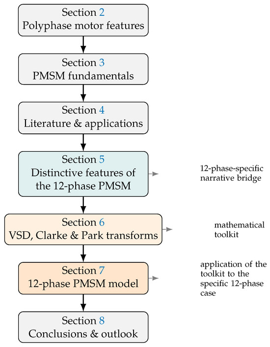
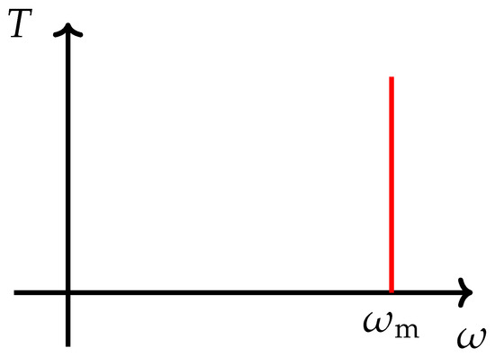
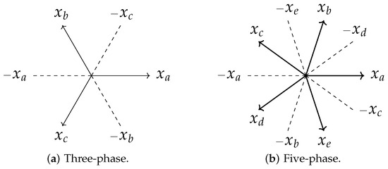
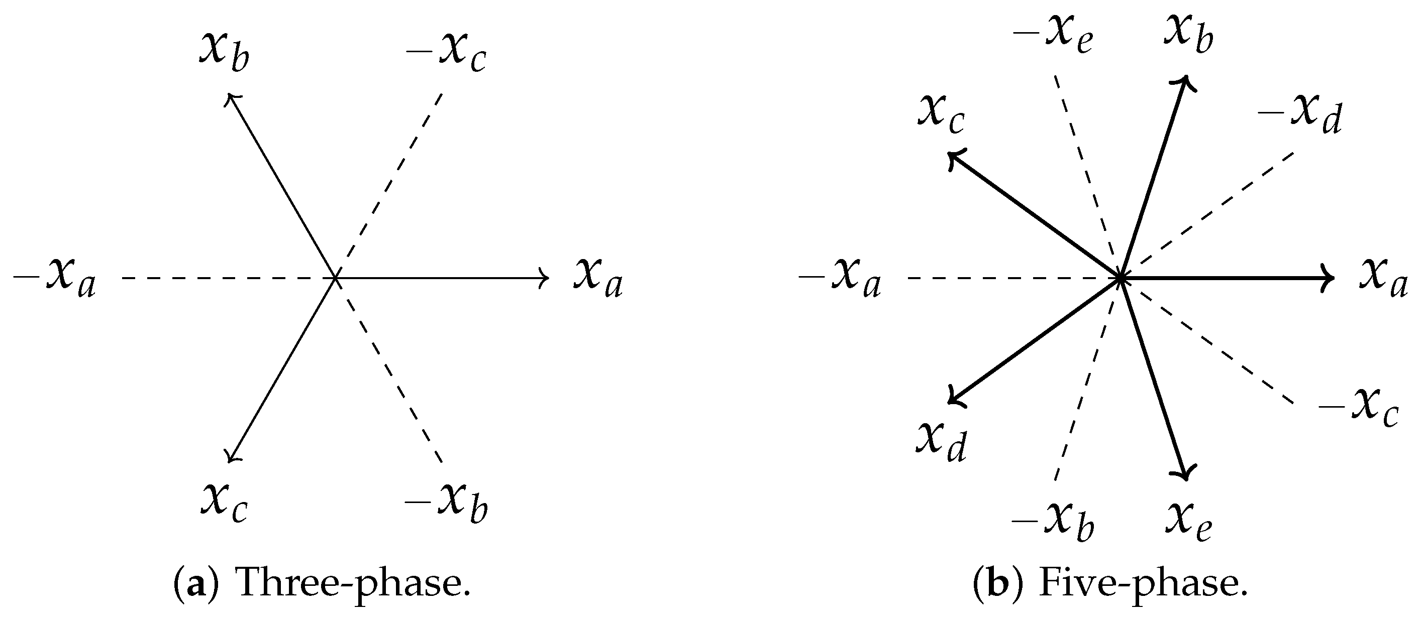
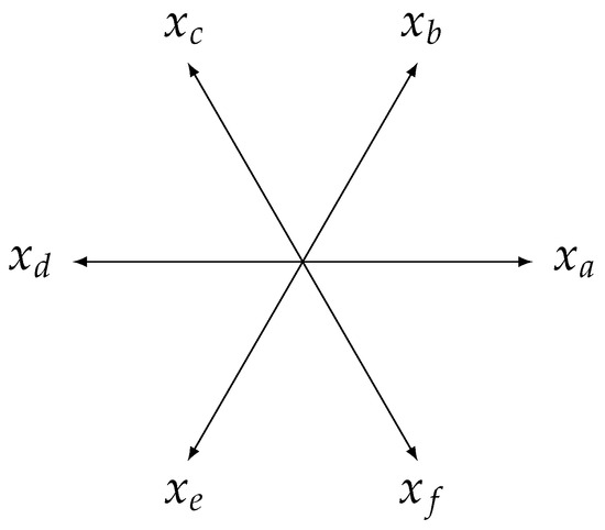
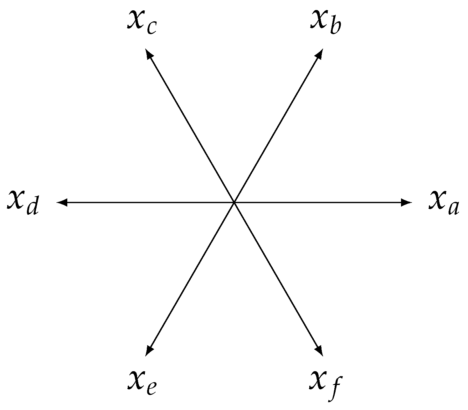
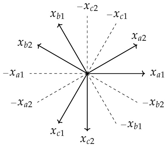
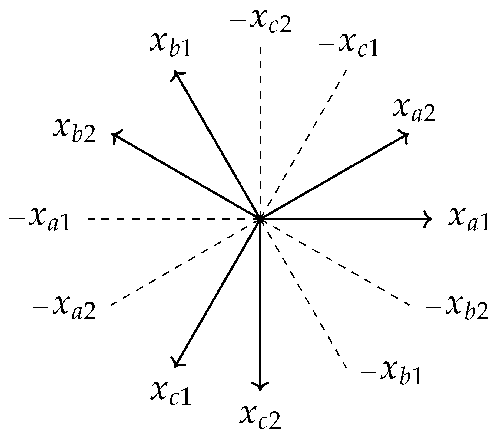


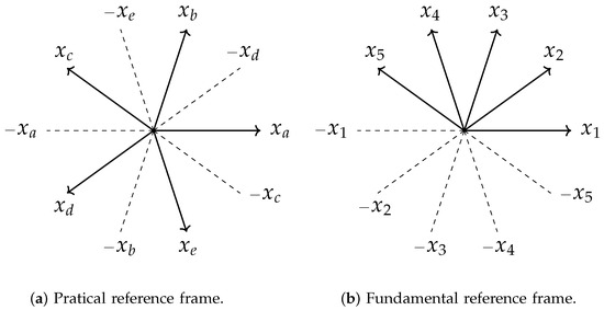
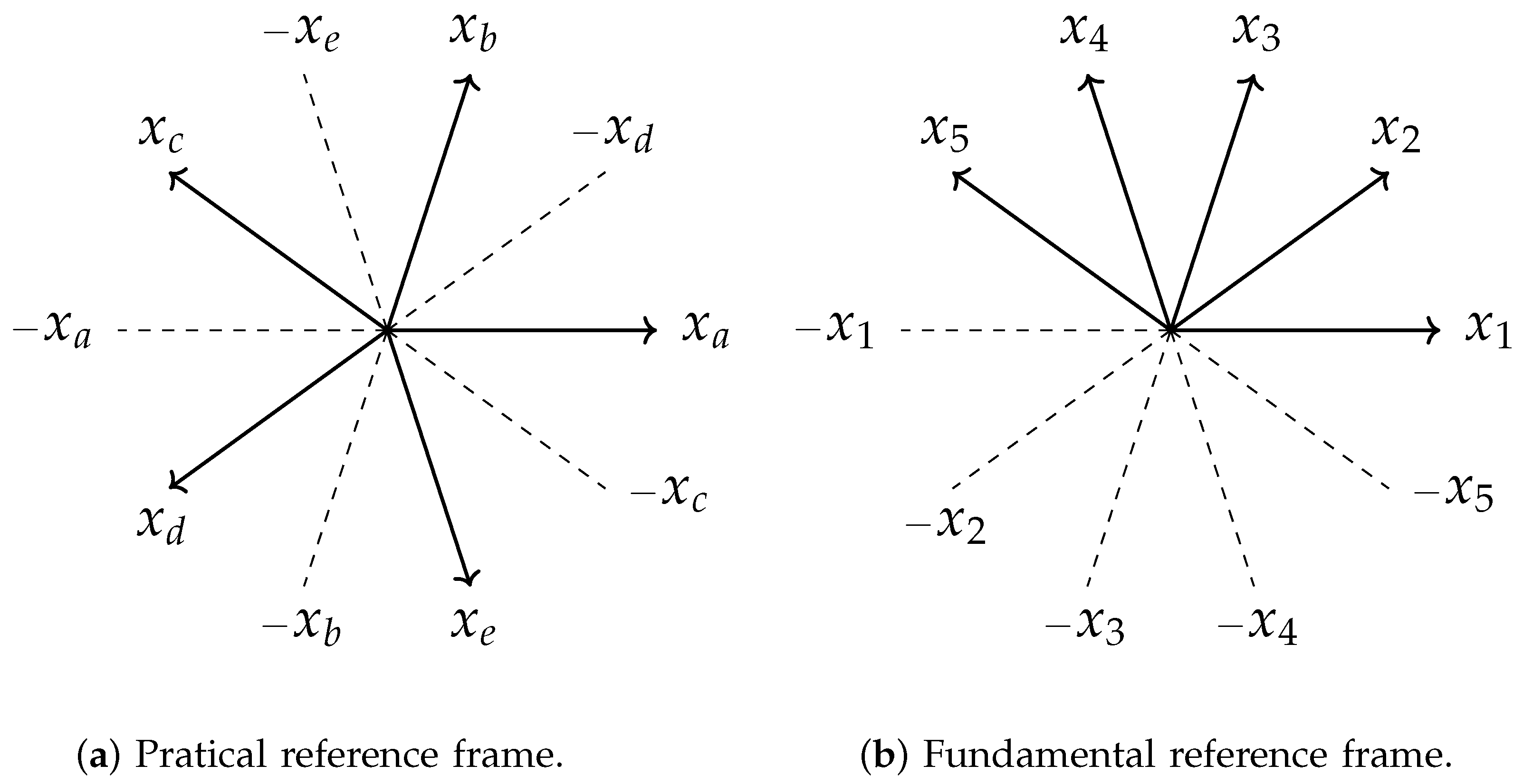
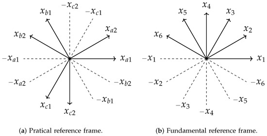
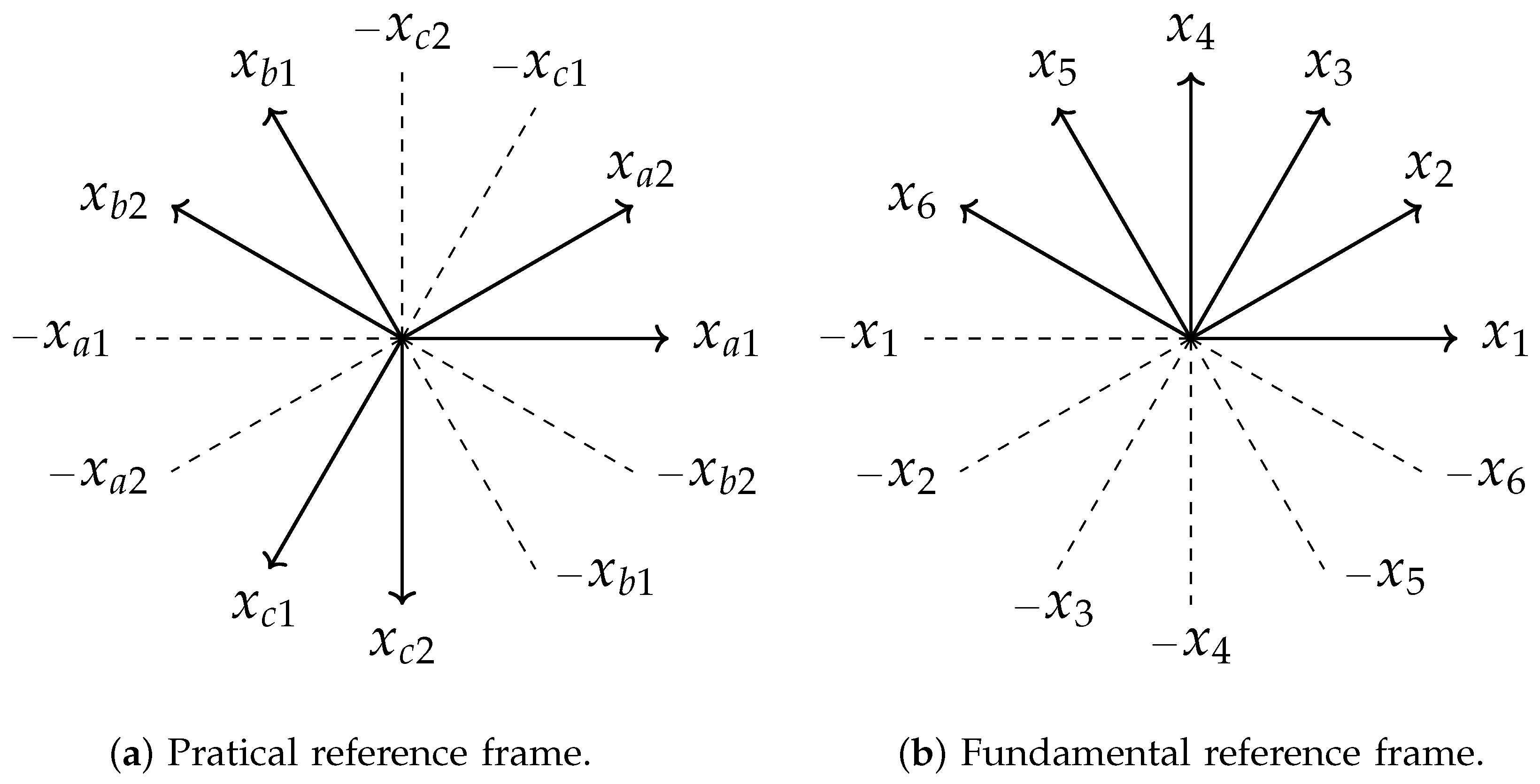
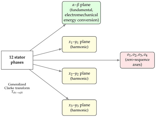
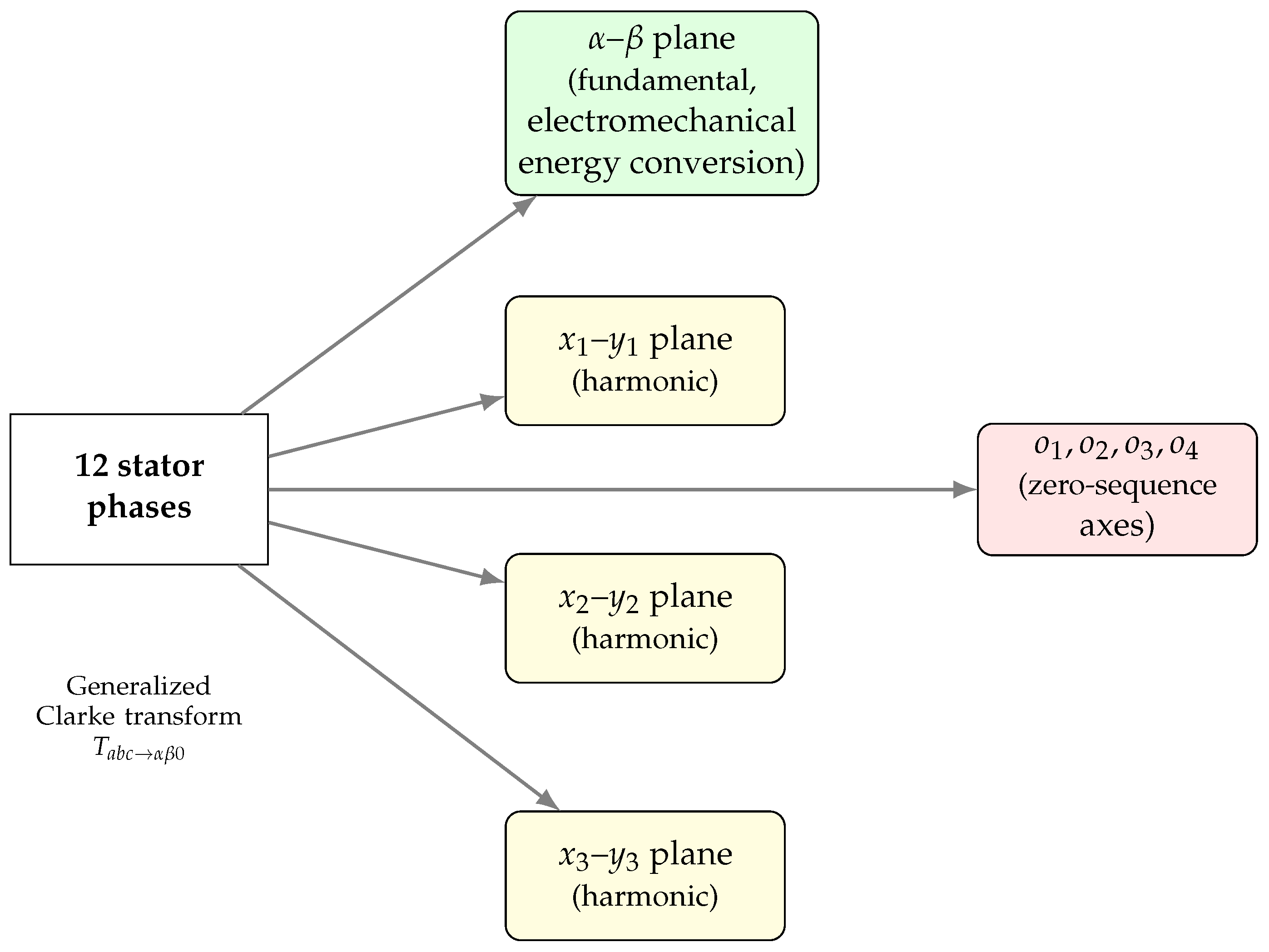
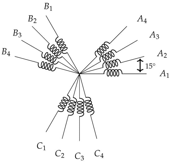
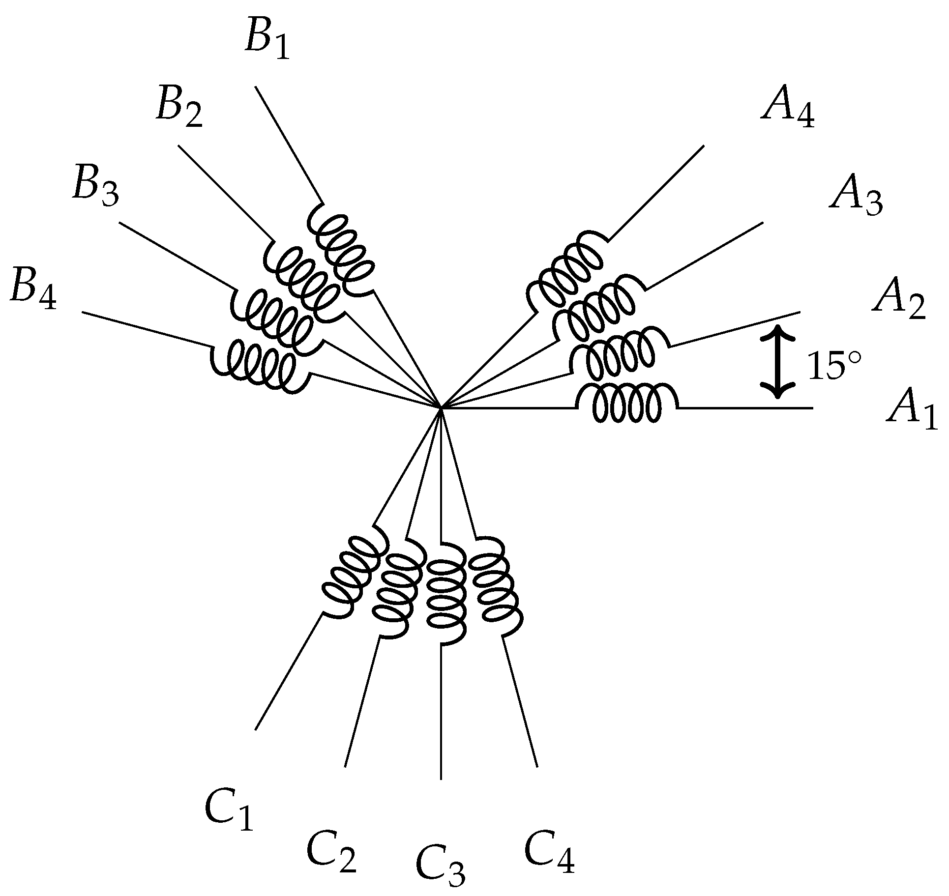
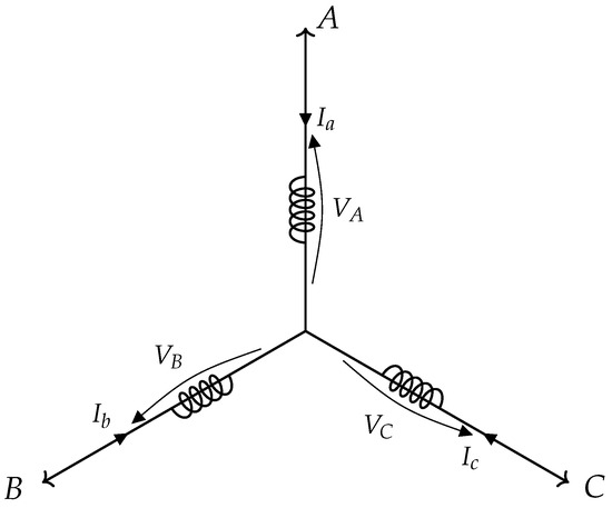
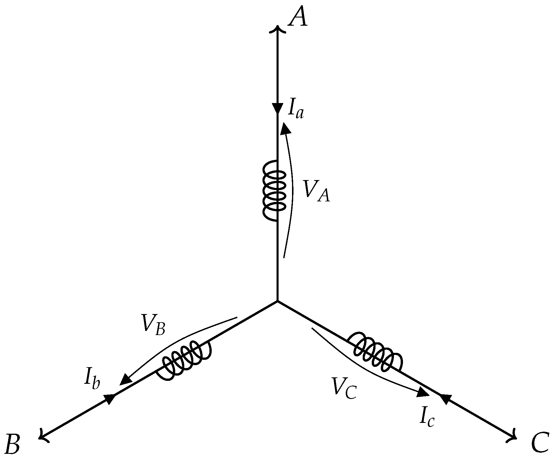
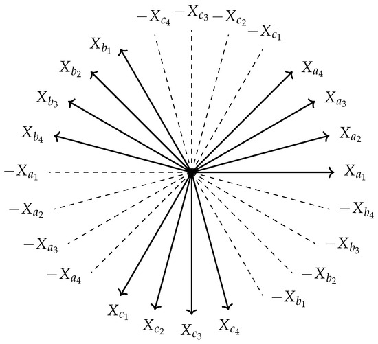
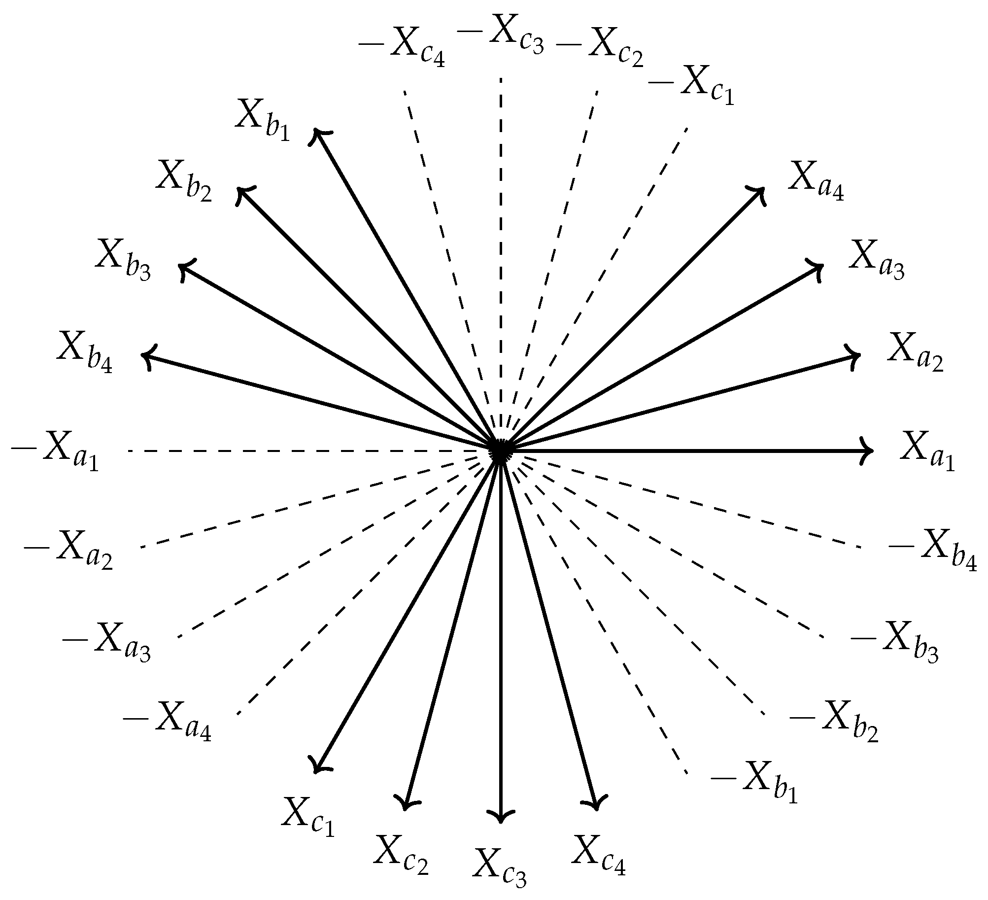
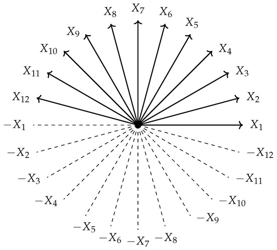
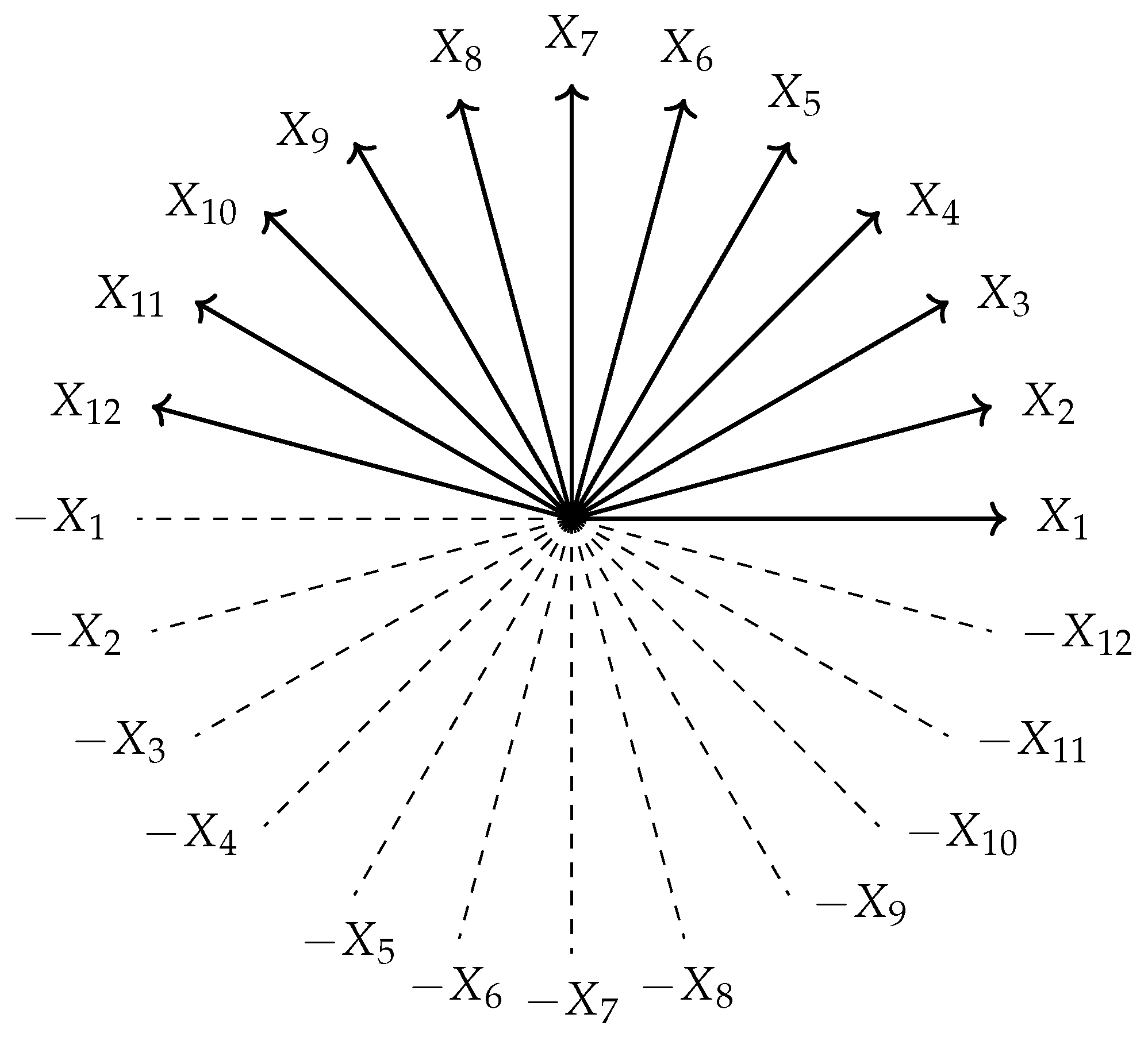
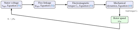
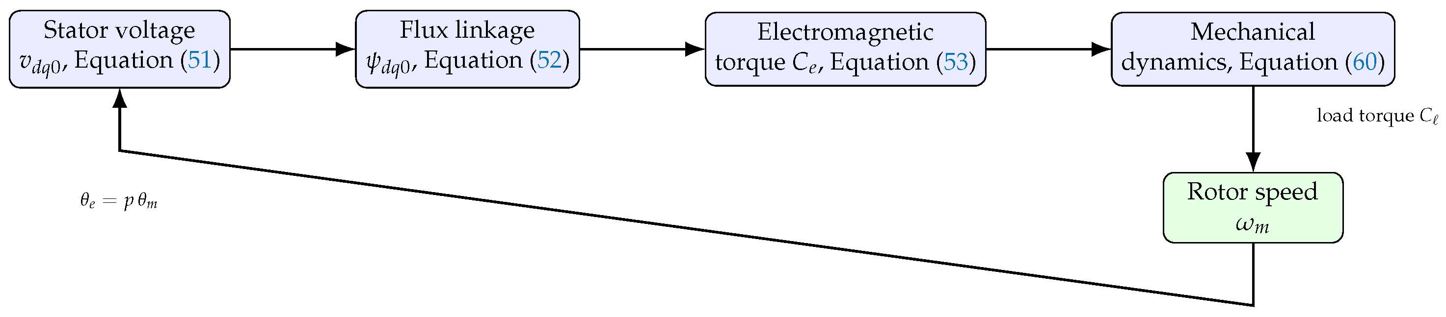
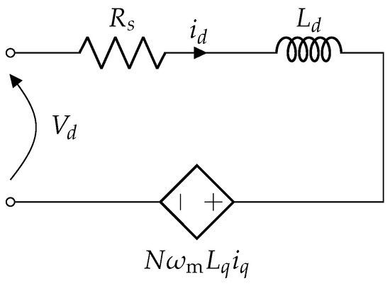
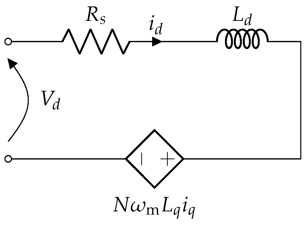
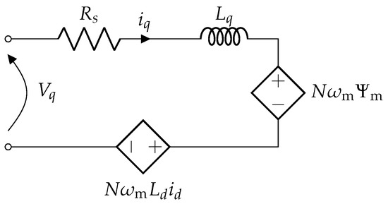
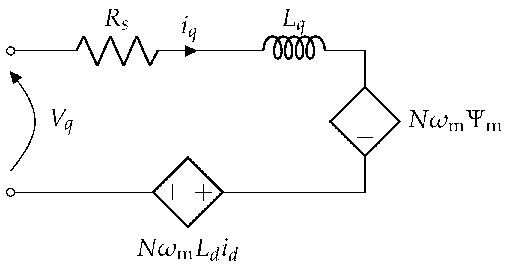

Disclaimer/Publisher’s Note: The statements, opinions and data contained in all publications are solely those of the individual author(s) and contributor(s) and not of MDPI and/or the editor(s). MDPI and/or the editor(s) disclaim responsibility for any injury to people or property resulting from any ideas, methods, instructions or products referred to in the content. |
© 2026 by the author. Licensee MDPI, Basel, Switzerland. This article is an open access article distributed under the terms and conditions of the Creative Commons Attribution (CC BY) license.