


Abstract
Interfacial bond failure is a common form of distress in rigid–flexible composite pavements, especially in tunnel environments with harsh service conditions. Epoxy-emulsified asphalt (EEA) is widely used as a high-performance interlayer bond coat, but its dynamic damage evolution under coupled thermomechanical loading remains insufficiently characterised. In this work, 45° static oblique shear tests and stress-controlled dynamic shear fatigue tests were performed on a C40 concrete-EEA-asphalt mixture composite system. Tests covered a temperature range of −10 °C to 45 °C, loading frequencies of 1 to 15 Hz, and three stress levels (0.3, 0.4, 0.5). An optimised geometric tangent method (GTM) was adopted to objectively locate the fatigue failure inflexion point, reducing the empirical bias inherent in traditional stiffness degradation analysis. Test results showed that an EEA application rate of 0.8 kg/m2 yielded the best overall interface performance, balancing mechanical interlocking and cohesive strength. At this application rate, the interfacial peak shear strength reached 1.72 MPa, with improved interfacial deformation compatibility and energy dissipation capacity. Fatigue damage followed a distinct three-stage stiffness degradation pattern. High temperatures and low loading frequencies accelerated rheological behaviour of the asphalt phase, shortened the stable damage propagation phase, and promoted premature interlayer slippage. Based on the experimental data, a phenomenological fatigue life prediction model was established, incorporating temperature, loading frequency and stress level. The model supports quantitative assessment of progressive interfacial damage and provides practical reference for structural durability design and life-cycle maintenance of composite tunnel pavements.
1. Introduction
Over recent decades, China’s transportation infrastructure development has advanced at an unprecedented pace, with highways and urban roads facing the dual challenges of increasing heavy-duty traffic and surging traffic volumes. To extend pavement service life and improve pavement serviceability, engineers have developed and applied various rigid pavement systems, including nano-SiO2 modified recycled brick aggregate concrete [1] (PCC), roller-compacted concrete [2] (RCC), jointed plain concrete [3] (JPC), and continuously reinforced concrete [4] (CRC). In the construction of new high-grade highways and the rehabilitation of existing concrete pavements, asphalt overlay layers are widely used for the overlay and repair of rigid concrete pavements owing to their inherent advantages of ease of construction, ride comfort, low noise, and low maintenance costs [5,6]. In this composite configuration, the underlying rigid concrete slab provides high compressive strength and structural bearing capacity, effectively distributing vertical wheel loads across the pavement section, while the flexible asphalt surface course serves to mitigate thermal deformation-induced stresses, absorb high-frequency vibrations, and provide a skid-resistant, wear-resistant interface. The complementary strengths of these two layers form a typical rigid–flexible composite pavement, which combines high structural bearing capacity with excellent ride comfort and pavement durability [7,8]. During in-service operation, a significant difference in elastic modulus exists between the rigid concrete base course (typically exceeding 30,000 MPa) and the asphalt surface course (typically 1000–5000 MPa), leading to mismatched thermal contraction and load-induced deformation behaviours between the two layers. These differential deformations induce significant shear stress concentrations at the interlayer bonding interface. Al-Qadi et al. [9] demonstrated through three-dimensional Accelerated Pavement Testing (APT) that in areas where vehicles brake, accelerate, or turn, peak shear stresses at the interlayer interface can reach several times those under steady-state driving conditions. When the interface shear stress exceeds the shear strength of the interlayer bonding materials, premature structural damage occurs, manifesting as interlayer slippage, delamination, and buckling, as well as bottom-up reflective cracking and fatigue damage. Such distress not only degrades the functional performance of pavements but also drastically reduces the design service life of composite pavement structures [10,11].
To enhance interlayer load-bearing coordination, the development and application of high-performance interlayer bonding agents have emerged as a key research priority in recent years. Conventional interlayer bonding agents are predominantly thermoplastic in nature, encompassing conventional emulsified asphalt, styrene-butadiene-styrene (SBS) modified asphalt, and high-viscosity asphalt. Although these agents satisfy fundamental performance criteria under typical service conditions, their intrinsic limitations become increasingly pronounced under the coupled effects of climatic variations and repeated traffic loading, compromising their ability to meet stringent shear resistance demands under extreme operating conditions [12,13,14]. Guedes [15] demonstrated that conventional thermoplastic bonding agents exhibit pronounced temperature dependency. When summer pavement surface temperatures exceed 60 °C, the materials tend to soften and undergo viscous flow, forming a “low-shear lubricating layer” at the interface, which causes a sharp decline in shear strength. In low-temperature environments, the materials are prone to brittle fracture and lose their stress–relaxation capability, rendering them unable to resist the crack-tip stresses induced by thermal contraction cracks in the underlying concrete base. Particularly in special application scenarios such as tunnel pavements, the semi-enclosed spatial structure results in poor heat dissipation conditions and a pronounced heat accumulation tendency. In addition, the highly channelised nature of heavy-duty traffic, coupled with frequent vehicle braking and acceleration manoeuvres, generates significant horizontal shear stresses at the interlayer bonding interfaces of rigid–flexible composite pavements. Meanwhile, based on engineering considerations such as fire safety, tunnel pavement materials are required to simultaneously satisfy special functional requirements, such as flame retardancy. This significantly exacerbates the risk of interface bond failure under coupled multi-physics effects [16]. Interlayer shear failure in pavements results from the accumulation and evolution of micro-damage under long-term, repeated traffic loads [17,18,19].
To address the inherent performance deficiencies of thermoplastic materials, thermosetting epoxy asphalt (EA)-which forms a three-dimensional network structure through curing and cross-linking-has been increasingly adopted in tunnel and highway pavements owing to its excellent mechanical strength, high-temperature stability, rutting resistance, and fatigue life [20]. Nevertheless, traditional hot-mix epoxy asphalt imposes strict requirements on construction temperature and working window, has a narrow margin for error during construction, and leads to high energy consumption and emissions. As a derivative material, epoxy-emulsified asphalt (EEA) retains the high strength and strong bonding properties of epoxy resin while enabling construction at ambient or warm temperatures, substantially enhancing environmental friendliness and construction convenience. Kong et al. [21] demonstrated through micro-mechanical analysis and scanning electron microscopy (SEM) observations that EEA in emulsion form has low surface tension and good permeability, allowing it to deeply penetrate the microscopic pore structure of the underlying cement concrete surface. As water evaporates through demulsification and the epoxy curing reaction proceeds, EEA forms a strong micromechanical interlock and a chemical bonding network at the rigid–flexible interface, thereby substantially enhancing the shear resistance and water-damage resistance of the pavement layers. Liu et al. [22] systematically quantified this performance improvement through direct shear tests, finding that the average shear strength, shear stiffness, and interlayer bond energy of the water-based epoxy-modified emulsified asphalt tack coat were 2.5, 2.1, and 2.4 times those of the unmodified emulsified asphalt control specimen, respectively, with the advantages being even more pronounced under high-temperature conditions. Theoretically, EEA can provide excellent static shear strength; however, over the decades-long design service life of a pavement, interface shear failure is rarely caused by a single extreme overload but rather stems from cumulative fatigue damage under repeated traffic loading [23]. Under high-frequency cyclic vehicle rolling, the interlayer shear stiffness of asphalt pavements undergoes irreversible degradation; when cumulative damage reaches a critical threshold, microcracks propagate to form macrocracks, leading to shear fatigue failure between layers. Current research on EEA and analogous high-performance interface materials, both domestically and internationally, has predominantly centred on evaluating static or quasi-static mechanical properties, including pull-out and direct shear strength, while detailed characterisation of dynamic damage evolution under coupled temperature-frequency-stress fields remains insufficient. Chang et al. [24] systematically tested the static shear strength of epoxy-emulsified asphalt tack coats under different application rates, test temperatures, and normal stress levels, and obtained adhesion and internal friction angle parameters using the Mohr-Coulomb failure criterion; Wang et al. [25] compared the interlayer static shear performance of different stress-absorption layer materials and established a correlation between material intrinsic properties and structural response.
Over the past decade, a growing body of research has focused on dynamic fatigue performance characterisation. Li et al. [26] developed a custom direct shear fatigue apparatus capable of applying controlled normal pressure and established a phenomenological model describing interlaminar shear fatigue behaviour. Rahman et al. [27] found through four-point bending shear fatigue tests that, under medium-to-high temperature conditions, the sensitivity of composite fatigue life to the amplitude of the applied shear stress exhibits exponential growth. Cao et al. [28] and Nian et al. [29] separately investigated the degradation patterns of interfacial fatigue life under external environmental conditions, focusing on the mean texture depth (MTD) of the substrate surface, the rheological properties of waterproof bonding materials, and water-heat-freeze–thaw cycles, respectively. To more realistically simulate the in situ stress state of the pavement, Yang et al. [30] and Ragni et al. [31] introduced cyclic dynamic shear testing (CDAC) and advanced shear rheometry techniques, demonstrating from the perspective of energy dissipation that cumulative damage caused by repeated loading is the fundamental mechanism of shear strength degradation. West et al. [32] conducted laboratory and field experimental research to evaluate the interfacial binding effect for the types of tack coat, the application rate (usage), the types of asphalt mixture, and the temperature. Among all the factors, the temperature showed the most pronounced influence; when the temperature increased, the interfacial bonding strength showed a bigger reduction. Lv et al. [33] further extended the study to the aggregate gradation characteristics of the mixture, investigating the effects of different macroscopic skeleton structures on shear stress transfer and fatigue damage evolution rates.
However, the shear fatigue behaviour of the EEA bond coat interface has not yet been systematically characterised. Most available studies focus on fatigue life under single or limited test conditions, and few have examined coupled damage evolution under the combined action of temperature, loading frequency and stress level. Furthermore, although the thermorheological properties of EEA govern its brittle-to-ductile transition under varying service temperatures, they are seldom linked to its macroscopic dynamic shear response. Traditional fatigue failure criteria, such as the widely adopted 50% stiffness reduction threshold, are largely defined on an empirical basis. When applied to complex viscoelastic-plastic modified asphalt systems, they lack rigorous physical justification and can introduce notable subjective bias into fatigue life estimation [34]. Bjørheim et al. [35] has critically noted that such methods, which rely heavily on subjective judgement, lack rigorous physical and mechanical constitutive foundations. Distortions in the underlying data directly cause fatigue life prediction models based on Paris’s law or Miner’s linear cumulative damage rule to undermine the engineering predictive accuracy.
To address these gaps, this work investigates the shear fatigue behaviour of a C40 concrete-EEA-asphalt mixture composite system. The main contributions are summarised as follows:
(1) The coupled effects of a full temperature range (−10 °C to 45 °C), a wide loading frequency band (1 to 15 Hz) and varying stress levels on the shear fatigue performance of the EEA bond coat interface were systematically quantified;
(2) An interface fatigue failure criterion based on the geometric tangent method was established, which reduces subjective bias in fatigue life determination;
(3) A clear correlation was constructed between the three-stage stiffness degradation trajectory and the thermorheological behaviour of the EEA binder;
(4) A three-dimensional phenomenological fatigue life prediction model was developed for the interlayer interface, providing technical reference for structural design, life cycle assessment and maintenance of rigid–flexible composite pavements in tunnel engineering.
2. Specimen Preparation and Interlayer Shear Testing
2.1. Test Materials
C40 ordinary Portland cement concrete was adopted for the rigid base layer to replicate the rigid substrate of the studied rigid–flexible composite pavement. The concrete was prepared with P.O 42.5R early-strength ordinary Portland cement (per Chinese industry standards), river sand, crushed stone and water, at a mass mix proportion of 1:1.42:2.76:0.41 (cement: sand: crushed stone: water). High-performance epoxy-emulsified asphalt (EEA) served as the interlayer bonding material. It was formulated from Grade 70 base asphalt, bisphenol A epoxy resin (E-51) and a water-based polyamide curing agent, and was supplied by Guangzhou Jiabaili Building Materials Co., Ltd., (Guangzhou, China). The flexible surface layer was fabricated with a standard SMA-13 gap-graded stone mastic asphalt mixture, with an optimum asphalt content of 5.8%; this material was supplied by Jinan Jiaodi New Materials Co., Ltd., (Jinan, China). Crushed limestone and limestone powder were used as the aggregate and mineral filler, respectively; both materials were sourced from the Xinlei Mineral Powder Factory, (Shijiazhuang, China). All physical and mechanical properties of the raw materials meet the requirements of Chinese industry standards JTG F40-2004 and JTG E42-2005. Key physical properties of the EEA binder, tested in accordance with the above standards, are listed in Table 1.
Table 1.
Key technical properties of the EEA binder.
2.2. Specimen Preparation
Pre-weighed coarse and fine aggregates were placed in an oven at 170–190 °C for thorough preheating, while the asphalt was heated to 150–170 °C. The preheated aggregates were added to the mixing drum and dry-mixed for approximately 30 s. Precise amounts of hot asphalt were then added, and wet mixing continued until the aggregate surfaces were completely and uniformly coated. Finally, mineral filler was added, and mixing continued for 30–60 s to form a homogeneous asphalt mixture.
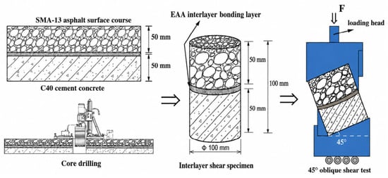
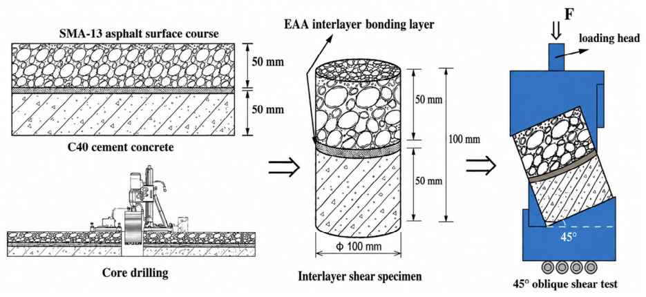
The surface of the cured C40 cement concrete base was roughened, and an epoxy-emulsified asphalt interlayer bond coat was sprayed uniformly at varying application rates. The freshly mixed asphalt mixture was then rapidly transferred into the mould and compacted to the specified elevation at 140–160 °C using a static compaction machine at a loading rate of 1 mm/min. The specimens were demolded after curing at room temperature for 24 h and then cured in a constant-temperature oven at 60 °C for 48 h. Large composite slabs with dimensions of 300 × 300 × 100 mm were fabricated to replicate field compaction and interlayer bonding conditions. Each slab consisted of a 50 mm-thick concrete base layer and a 50 mm-thick SMA-13 surface layer. After standard curing, cylindrical composite core specimens (100 mm in diameter) were drilled from the slabs using a core drill. Wet coring was adopted to avoid thermal damage to the EEA bond coat and mechanical microcrack initiation at the rigid–flexible interface. Drilling was performed at a controlled, low feed rate with continuous circulating cooling water. Cores extracted within 50 mm of the slab edge were discarded to eliminate anomalies induced by boundary effects. Four replicate specimens were prepared for each test condition to ensure the statistical validity and reproducibility of the test results. The formed composite specimens were then cored with a 100 mm-diameter core drill bit, as shown in Figure 1.
Figure 1.
Preparation of interlayer shear specimens and 45° oblique shear test apparatus.
2.3. Interlayer Shear Fatigue Test
The 45° oblique shear test enables the simultaneous application of shear stress and normal compressive stress; compared with conventional horizontal direct shear tests, it more closely replicates the composite stress state within the pavement structure under vehicle loads [27]. Numerous experimental investigations conducted worldwide have confirmed that normal confining forces exert a substantial influence on the shear resistance of interlayer bonding interfaces [36,37]. Consequently, the 45° oblique shear test has become one of the primary technical approaches for evaluating the interlayer shear strength of tunnel and highway pavement layers.
2.3.1. Static Oblique Shear Test
Under emergency braking conditions, the interlayer interface of rigid–flexible composite pavements is subjected to severe combined shear-compressive stress states, which are the dominant mechanical drivers of premature structural defects such as interlayer slippage and horizontal displacement. To quantitatively characterise the shear failure behaviour of composite specimens under this complex multiaxial stress field, the present study utilised a custom-fabricated 45° oblique shear fixture mounted on a universal testing machine (UTM) to conduct static interlayer shear strength tests. A 100 mm-diameter cylindrical composite core specimen, properly fabricated and cured, was placed in a temperature-controlled chamber for conditioning. All specimens were maintained at 25 °C for at least 4 h to ensure that the specimens’ internal temperature distribution reached a uniform equilibrium.
In interlayer shear performance characterisation, the loading rate constitutes a critical control parameter that exerts a profound influence on the variability of test results and their engineering applicability. For the interface bonding between concrete bases and hot mix asphalt (HMA) surface layers, Jia et al. [38] performed a series of oblique shear tests at a constant displacement loading rate of 10 mm/min and systematically compared the shear failure characteristics of three representative bonding layer material cohesive failure components: emulsified asphalt, bituminous mastic, and epoxy asphalt. Their results revealed that increasing temperature markedly diminishes the contribution of the cohesive component to the interfacial shear strength, and the energy dissipation process associated with cohesion displays pronounced temperature sensitivity; across the entire temperature range, the comprehensive shear performance of the epoxy asphalt bonding layer was significantly superior to that of the other two materials. Collectively, these findings provide robust validation for the rationality and general applicability of the 10 mm/min loading rate in interlayer oblique shear testing protocols. Therefore, all static interlayer shear tests were performed under constant displacement control, with the loading rate set to 10 mm/min. Vertical load and crosshead displacement data were acquired continuously throughout the test duration until complete interlayer shear slippage occurred and a well-defined load plateau in the load–displacement response curve, at which point the test was terminated. The interlayer shear strength τ was calculated according to Equation (1):
where Fmax is the maximum failure load (N); α is the inclination angle of the shear fixture (45°); A is the cross-sectional area of the cylindrical core specimen (100 mm in diameter), calculated as A = πd2/4 ≈ 7854 mm2. At least four tests were performed for each type of specimen to ensure test repeatability.
2.3.2. Oblique Shear Fatigue Tests
Conventional static shear strength merely characterises the ultimate interfacial load-bearing capacity under monotonic, instantaneous loading and fails to capture the mechanisms of progressive damage evolution under long-term, cyclic, repeated traffic loads. Based on the results of static interlaminar shear strength tests, the present work performed complementary interlaminar oblique shear fatigue tests under a stress-controlled loading mode. Two primary loading modes are widely adopted in pavement fatigue testing: stress-controlled and strain-controlled. The stress-controlled mode is suitable for fatigue failure scenarios involving high stress magnitudes and low cycle counts; it features lower data dispersion, requires fewer replicate specimens, and offers reliable precision control. Considering that the interlayer interfaces of composite rigid–flexible pavements are subjected to high shear stress levels under heavy traffic loads, and given that this study focuses on the fatigue failure characteristics of the interfaces at high stress magnitudes, the stress-controlled loading mode was selected for the tests.
The tests employed a half-sine (Haversine) loading waveform to simulate the pulsed dynamic characteristics of in situ traffic loads [39]. Dynamic traffic loads on highways are random in nature, governed by multiple factors such as pavement roughness, vehicle classification, and operating speed; accurately characterising their randomness using statistical methods is challenging. Extensive prior research has confirmed that the Haversine waveform can effectively simulate the process by which vehicle loads act on the pavement; the loading phase corresponds to the process of the wheel rolling over the pavement, while the unloading phase corresponds to the process of the wheel leaving the pavement, accurately reflecting the pulsating nature of traffic loads.
To systematically investigate the coupled influences of temperature, vehicle speed, and stress level on interfacial fatigue life, three key test parameters were varied in this study, including temperature, stress level, and loading frequency.
(1) Temperature
The test temperatures were set at −10 °C, 0 °C, 15 °C, 30 °C, and 45 °C. This temperature range encompasses the full spectrum of in-service interlayer temperatures that interlayer interfaces in road pavements are likely to experience in most regions of China. Research by Xu et al. [40] indicates that temperature has a profound influence on interlayer shear fatigue life; when the temperature reaches 50 °C, the interlayer shear fatigue life of the pavement structure decreases sharply. Using 25 °C as a threshold, the rate of change in shear fatigue life with temperature can be divided into two phases: within the range of −10 °C to 25 °C, interlaminar shear fatigue life varies moderately across different temperatures; however, above 25 °C, fatigue life decreases exponentially with increasing temperature.
(2) Stress Levels
The stress level (S) is defined as the ratio of the shear stress applied in fatigue testing to the static shear strength measured at the corresponding test temperature. In this work, stress level describes the relative magnitude of applied loading (S = τ/τstatic), which differs from the cyclic stress ratio (R = σmin/σmax)-the conventional parameter describing the ratio of minimum to maximum stress within a single loading cycle. Three stress levels (0.3, 0.4, and 0.5) were adopted in the tests. This range covers the interlayer shear stress conditions of actual pavement structures under various traffic load levels. Zheng et al. [41] reported that when the stress levels were increased from 0.3 to 0.4, the interlayer shear fatigue failure life of asphalt mixtures decreased by approximately 60%–65%, indicating that the stress levels are one of the key factors affecting interlayer fatigue life.
(3) Loading Frequency
Vehicle speed determines the duration of traffic loads acting on the road structure and the corresponding rest intervals; higher speeds result in shorter loading durations and longer rest intervals. The test parameters were set to four loading frequencies: 1 Hz, 5 Hz, 10 Hz, and 15 Hz [33,42,43]. According to relevant domestic and international research findings, a loading frequency of 1 Hz corresponds to a driving speed of approximately 20 km/h, 5 Hz to approximately 40 km/h, 10 Hz to approximately 60 km/h, and 15 Hz to approximately 80 km/h. This frequency range covers the typical operating speed range on China’s highways.
Traditional failure criteria based on stiffness declining to 50% of the initial value have significant limitations in complex composite structures. The stiffness degradation threshold corresponding to the onset of the third stage can fluctuate between 30% and 50% under different loading conditions, which can easily lead to subjective biases in fatigue life assessment results [44].
To address the inherent subjectivity and inaccuracies of traditional failure criteria, the present work adopts the geometric tangent method (GTM) to objectively determine the critical fatigue failure inflexion point. This method is based on the three-stage evolution of the stiffness degradation curve: the first stage is the initial damage stage, marked by an abrupt initial stiffness drop; the second stage is the steady-state damage stage, characterised by a slow, approximately linear decay in stiffness; the third stage is the accelerated failure stage, during which stiffness drops sharply until complete failure occurs. The implementation procedure for GTM is detailed as follows: First, the stiffness-cycle data obtained from the test are smoothed. Subsequently, tangent equations are fitted separately for the second stage (stable damage stage) and the third stage (accelerated failure stage). The intersection point of the two tangents is taken as the critical point of fatigue failure, and the cycle count corresponding to this point is the fatigue life of the specimen. Unlike conventional criteria that rely on arbitrary, fixed stiffness-reduction thresholds, GTM identifies the failure point solely based on the intrinsic evolution characteristics of the experimental data. This effectively eliminates the subjective human intervention and significantly improves the objectivity and reproducibility of fatigue life evaluations. Wang et al. [45], in their study on the fatigue crack propagation behaviour of asphalt under dynamic shear loading, confirmed that the failure point determined by the geometric tangent method shows a high degree of consistency with the time of macroscopic crack initiation, and the coefficient of variation in its evaluation results is 41.2% lower than that of the traditional 50% stiffness decay criterion. By fitting the interlayer shear fatigue life corresponding to different stress ratios in a double-logarithmic coordinate system, a classical phenomenological fatigue life prediction model was established [35]. The fitting formula is given by (2):
where log(τ/τmax) is the logarithm of the stress level; τmax is the maximum shear strength, 0 < τ < τmax; k is the slope of the fatigue-life curve; and b is the intercept of the logarithmic fatigue curve.
3. Results and Discussion
3.1. Determination of Optimal Interlayer Bond Coat Application Rate
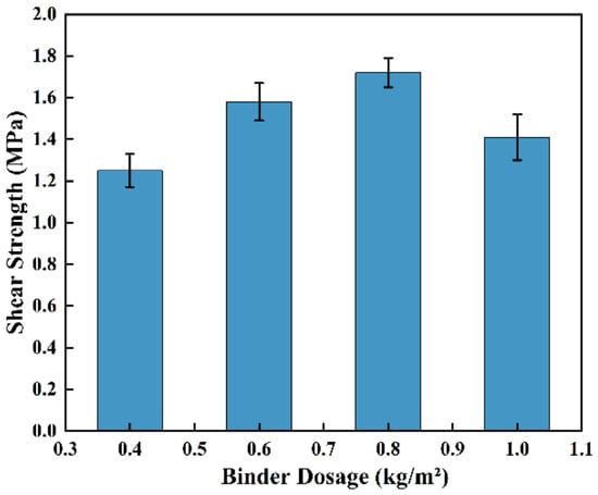
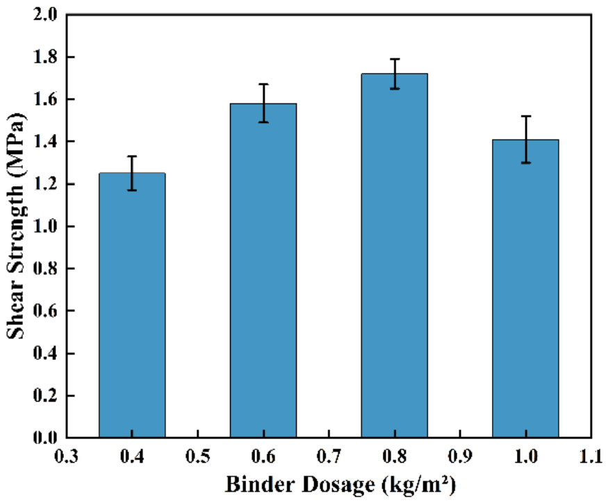
Static oblique shear tests were performed at a controlled ambient temperature of 25 °C to assess the interlayer shear performance of specimens prepared with varying epoxy-emulsified asphalt (EEA) bond coat application rates and to determine the optimal application rate. As shown in Figure 2, when the application rate of epoxy-emulsified asphalt (EEA) increased from 0.4 kg/m2 to 1.0 kg/m2, the interlayer shear strength exhibited a typical inverted U-shaped trend. When the application rate increased to 0.8 kg/m2, the shear strength reached a peak of 1.72 MPa, representing an increase of approximately 37.6% compared to the 0.4 kg/m2 group; however, further increasing the application rate to 1.0 kg/m2 resulted in a significant 18.0% reduction in shear strength. The error bars in Figure 2 represent the standard deviation of four replicate specimens under each test condition, indicating that the test results show good reproducibility.
Figure 2.
Effect of epoxy-emulsified asphalt (EEA) bond layer application rate on average interlayer shear strength (error bars indicate the standard deviation of four replicate specimens).
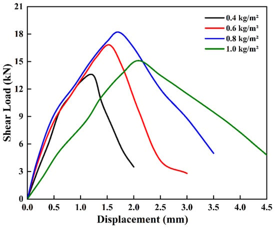
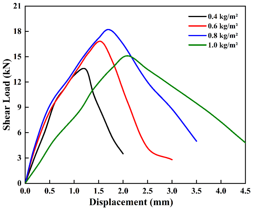
The initial slope of the load–displacement curve reflects the macroscopic shear stiffness of the interlayer bonding system, expressed in units of kN/mm. To characterise the intrinsic mechanical properties of the material and align the units (MPa) with the stress levels adopted in subsequent fatigue analysis, the “initial stiffness” in this study is quantitatively defined as the initial composite shear modulus. This value is derived by converting the linear elastic segment of the load–displacement curve into a shear stress–strain relationship: the shear load is divided by the specimen cross-sectional area (A), and the measured displacement is divided by the theoretical effective thickness of the bonded layer. As shown in Figure 3, at lower application rates (0.4 kg/m2), the EEA adhesive could not fill the surface texture of the cement concrete base course, leading to insufficient effective bonding area and premature brittle interfacial debonding failure [21]. This gives the interface high initial shear stiffness, but premature failure occurs through brittle interfacial delamination even at relatively low peak loads. When the application rate reached 0.8 kg/m2, the EEA formed a continuous and dense effective bonding film in the interlayer bonding systems. This film harnessed the high adhesive strength of the cured epoxy resin’s three-dimensional cross-linked network, while simultaneously enhancing the mechanical interlocking between the rigid base and the asphalt surface through complete texture filling. This balanced state delivers optimal interfacial load-bearing capacity, with greater pre-peak displacement and notably enhanced toughness and energy dissipation capacity. Conversely, when the application rate was too high, the excess asphalt could not be absorbed by the base and surface layers, accumulating at interlayer bonding systems to form an excessively thick layer of free asphalt. This film acted as a ‘lubricant’ within interlayer bonding systems, shifting the failure mode from interfacial debonding to internal cohesive failure of the bond coat [46]. Although the system shows high apparent ductility driven by viscous flow of excess free binder, its overall stiffness and shear strength are substantially reduced. Therefore, 0.8 kg/m2 was adopted as the optimal application rate for all subsequent tests.
Figure 3.
Static oblique shear load–displacement curves of rigid–flexible composite specimens with different EEA application rates.
3.2. The Effect of Temperature on the Interlayer Shear Mechanical Response
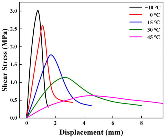
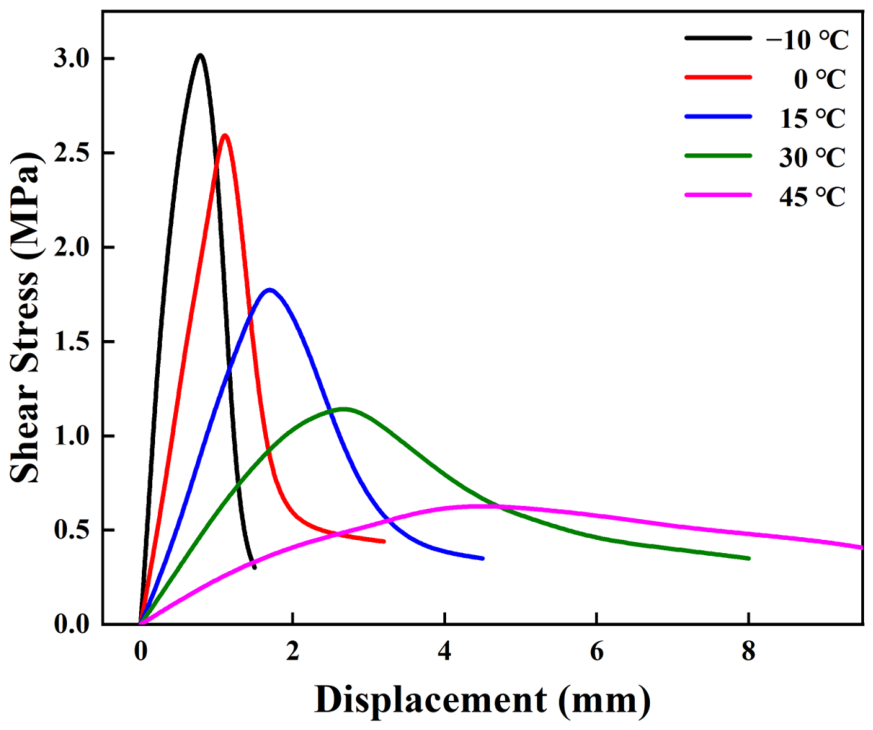
Static oblique shear tests were performed across a wide temperature range from −10 °C to 45 °C, to characterise the temperature-dependent mechanical response of the EEA bond coat interface in rigid–flexible composite pavements. Quadruplicate composite specimens were tested at each temperature to quantify experimental scatter and ensure dataset reliability. Prior to testing, all specimens were conditioned in a temperature-controlled chamber and held at the target temperature for a minimum of 4 h to ensure uniform thermal equilibrium throughout the specimen. Across all test temperatures, the coefficient of variation in peak failure load for the four replicates was below 8.5%, indicating good reproducibility despite the inherent heterogeneity of the concrete-asphalt composite system. The shear load–displacement curves presented in Figure 4 are representative curves selected from replicate test results, and illustrate the macroscopic deformation characteristics of the interface at each temperature. The results show that the mechanical behaviour of the EEA interlayer transitions from brittle to ductile with increasing temperature. At the low temperature of −10 °C, the curve displayed typical brittle fracture characteristics, with an extremely high peak failure load; however, after reaching the peak, the load dropped rapidly without a noticeable plastic deformation stage. This was primarily attributed to the glass transition of both the epoxy resin crosslinked network and the matrix asphalt phase under low-temperature conditions, which severely restricted the thermal motion of the polymer chains. As a result, the material exhibited exceptionally high elastic modulus and macroscopic shear stiffness, but possessed extremely low deformability [47]. When the temperature increased to 15 °C and 30 °C, the viscoelastic properties of the system gradually became prominent, and the failure displacement increased markedly. At this intermediate temperature interval, the three-dimensional confinement effect of the epoxy resin crosslinked network and the viscoelastic rheological behaviour of the asphalt phase reached a dynamic equilibrium state. Consequently, the system exhibited superior elastoplastic coordinated deformation capacity and high energy dissipation toughness. The failure displacement of specimens increased markedly, and the failure mode gradually transitioned from interfacial debonding to cohesive failure within the bond coat. At a high temperature of 45 °C, the asphalt phase completely transitions to a viscous flow state, and the stiffness of the epoxy resin cross-linked network also decreases significantly. The specimens exhibit pronounced flow-plastic characteristics, the peak failure load decreases significantly, and the failure mode at interlayer bonding systems is dominated by shear flow within the bond layer. This indicates that composite pavements are highly prone to interlayer slippage under high-temperature conditions, and their long-term service performance needs to be further quantified through fatigue testing.
Figure 4.
Static oblique shear load–displacement curves of rigid–flexible composite specimens under various temperatures.
3.3. Coupled Effects of Temperature and Loading Frequency
3.3.1. Determination of the Optimal Application Rate of EEA
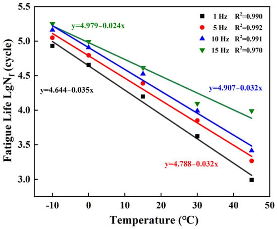
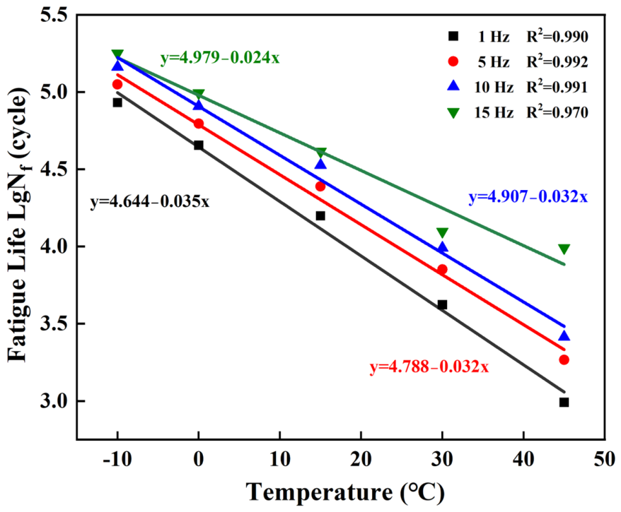
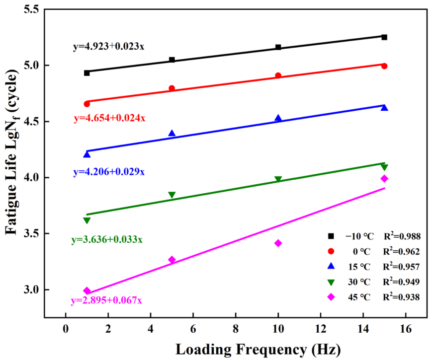
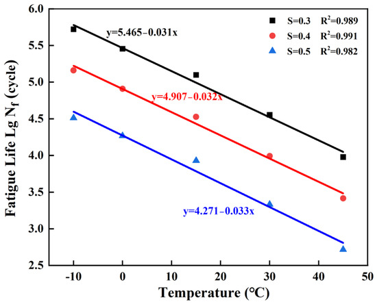
Figure 5 and Figure 6 illustrate the variation in interlayer shear fatigue life under the combined influence of temperature and loading frequency. In a double-logarithmic coordinate system, the logarithm of fatigue life (lg Nf) showed a strong negative linear correlation with temperature, as shown in Figure 5. According to the regression slope (approximately 0.032/°C), a 15 °C temperature rise at a fixed loading frequency reduces specimen fatigue life by a factor of roughly 3. This is because elevated temperatures weaken the intermolecular forces of the EEA binder, thereby reducing the deformation resistance of the EEA bond coat.
Figure 5.
Interlayer shear fatigue life versus temperature at different loading frequencies.
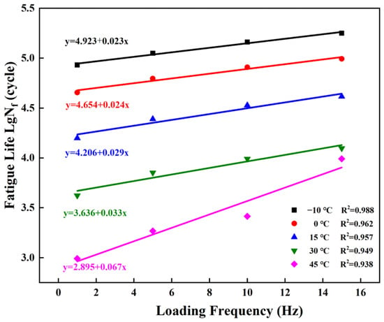
Figure 6.
Interlayer shear fatigue life versus loading frequency at different temperatures.
As shown in Figure 6, fatigue life increased significantly with increasing loading frequency. Fatigue life was shortest under low-frequency loading conditions of 1 Hz, while fatigue life was maximised at 15 Hz. Based on viscoelastic rheological principles, the duration of a single pulse loading cycle under high-frequency conditions was extremely short, such that the interlayer bonding material could not develop sufficient stress relaxation to produce irrecoverable viscoplastic strain. This hysteresis effect under high-frequency conditions significantly reduced the micro-creep damage induced by a single cycle, lowered the damage accumulation rate, and consequently substantially extended the fatigue life of the interlayer bonding interface at the macroscopic scale.
3.3.2. Evolution of Initial Stiffness and Cumulative Dissipated Energy
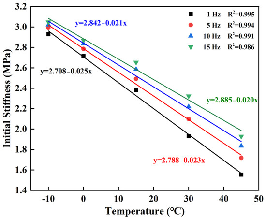
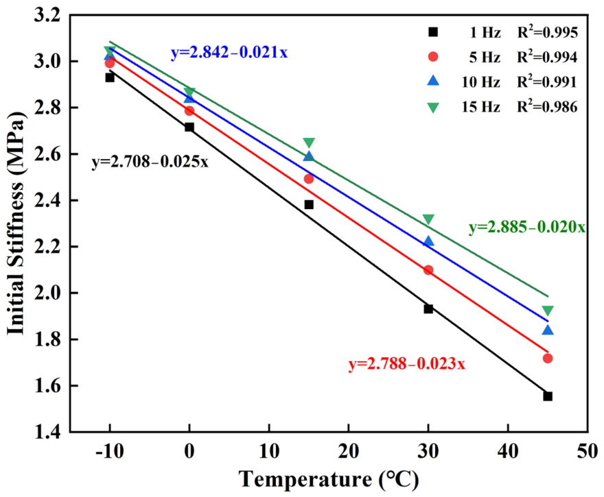
Initial stiffness, quantified as the initial shear modulus in MPa in this work, serves as a baseline reference for assessing fatigue damage initiation and reflects the initial deformation resistance of the interlayer bonding system under cyclic loading. The test results in Figure 7 indicated that the initial stiffness at all loading frequencies exhibited a strong linear decreasing trend with increasing temperature (R2 > 0.98). Within the same temperature interval, the higher the loading frequency, the greater the initial stiffness; this mechanical behaviour is highly consistent with the time-temperature superposition principle (TTSP) for asphalt materials.
Figure 7.
Changes in initial stiffness with temperature under various loading frequencies.
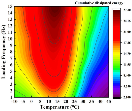
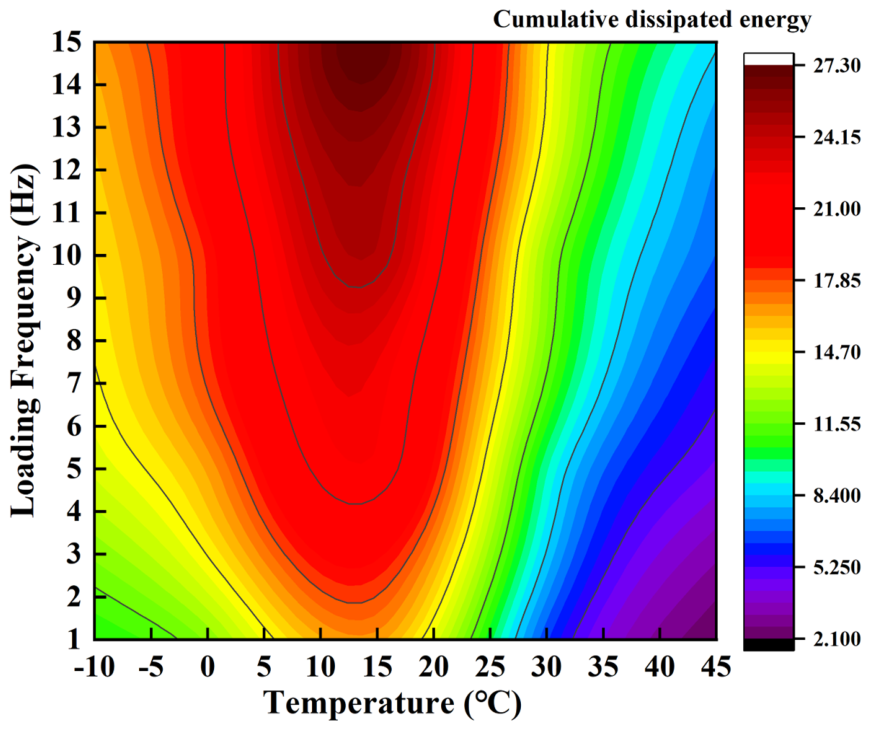
Based on the contour plot of cumulative dissipated energy (Figure 8), the mechanisms of energy dissipation and damage evolution during the fatigue process were further analysed. Test results revealed that the peak regions of cumulative dissipated energy (red high-energy zones) were primarily concentrated in the moderate temperature range of 10 °C to 15 °C and the high-frequency loading range of 12 Hz to 15 Hz. Under extremely low-temperature conditions of −10 °C, although the material exhibited an exceptionally high elastic modulus and could sustain elevated stress levels, the system displayed typical characteristics of a rigid glassy state. The plastic strain accumulated per loading cycle was negligible, resulting in a very limited hysteresis loop area, which prevented significant energy dissipation via viscoelastic deformation mechanisms. In contrast, at a high temperature of 45 °C, the material modulus dropped substantially, and its bearing capacity decreased sharply, which also restricted the generation of large dissipated energy. Therefore, under moderate temperature conditions, the material’s stress and strain are well-matched, resulting in optimal energy storage and dissipation behaviour; this is also the optimal service condition where such materials exhibit the best overall performance.
Figure 8.
Contour plot of cumulative dissipated energy against temperature and loading frequency.
3.3.3. Sensitivity of Fatigue Performance to Stress Level
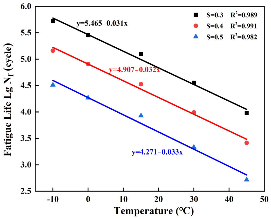
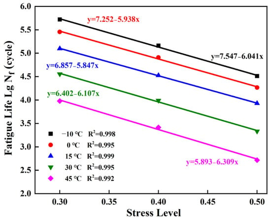
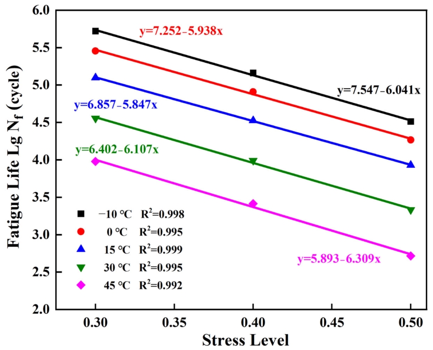
Figure 9 and Figure 10 illustrate the variations in interlayer shear fatigue life for stress levels of 0.3, 0.4, and 0.5. As shown in Figure 9 and Figure 10, an increase in stress level sharply accelerated the fatigue failure process at the interlayer interface. Linear fitting of the data revealed that, across all test temperatures, lgNf maintained a highly linear correlation with the stress level, with a coefficient of determination R2 exceeding 0.99. When the stress level increased from 0.3 to 0.5, the fatigue life of the specimens decreased significantly under all temperature conditions. The pronounced sensitivity of fatigue life to applied stress level originates from accelerated degradation of the interfacial microstructure. At a low stress level (S = 0.3), dynamic shear stress is primarily accommodated by elastic deformation of the three-dimensional cross-linked epoxy network and internal friction between interlocked aggregates. localised microdamage accumulates steadily under this condition, accompanied by considerable energy dissipation. When the stress level increases to 0.5, cyclic shear stress exceeds the elastic recovery threshold of local microstructures. The elevated energy input induces widespread microcracking at the aggregate–binder interface and accelerates irreversible fracture of the thermosetting epoxy network.
Figure 9.
Interlayer shear fatigue life versus temperature at different stress levels.
Figure 10.
Interlayer shear fatigue life versus stress level at different temperatures.
This stress-induced degradation mechanism shows a clear coupling effect with ambient temperature. At low temperatures (−10 °C to 0 °C), the asphalt matrix remains in a rigid glassy state, and high stress levels directly trigger rapid brittle propagation of microcracks, shortening the stable damage propagation phase. At high temperatures (30 °C to 45 °C), the asphalt phase softens and undergoes significant viscous flow, such that the epoxy network bears the majority of the applied load. Under these conditions, high cyclic stress levels readily overcome the reduced cohesive flow resistance of the binder, accelerating viscoelastic shear deformation and leading to premature macroscopic slippage failure. Accordingly, limiting peak interfacial shear stress is essential for preserving the long-term structural integrity of composite pavements across varying climatic conditions.
3.4. Interlayer Shear Fatigue Performance and Damage Evolution Mechanisms
3.4.1. Initial Stiffness Characteristics and Fatigue Life Estimation
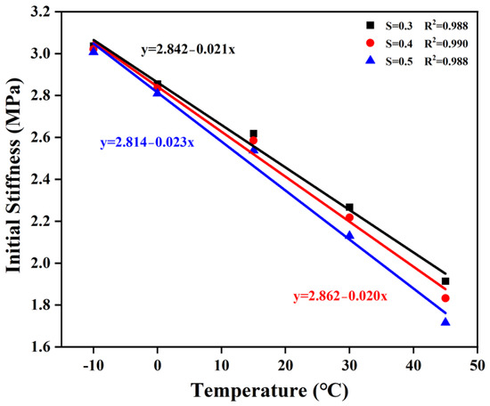
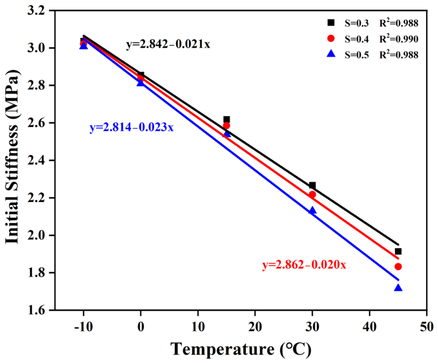
Initial stiffness serves as a critical benchmark for evaluating a material’s initial resistance to deformation under fatigue, while the decay of stiffness with loading cycles intuitively reflects the accumulation of internal damage within the material. As shown in Figure 11, the initial stiffness exhibited a distinct linear decrease with increasing temperature. A comparison of different stress conditions revealed that higher stress levels resulted in lower initial stiffness values, indicating that high loads induced microcrack formation during the early stages of loading.
Figure 11.
Initial stiffness versus temperature under different stress levels.
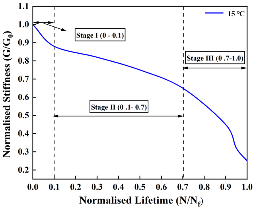
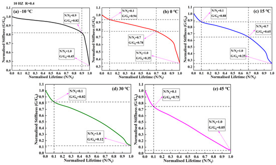
To address the subjectivity and empirical bias inherent in the traditional failure criterion (stiffness reduced to 50% of its initial value) for complex composite structures, this study adopted an optimised geometric tangent method (GTM) to objectively locate the critical inflexion point of fatigue failure. The term “optimised” denotes the use of statistically validated fixed intervals for tangent fitting, rather than relying on visual inspection or empirical judgement. As shown in Figure 12, the normalised stiffness degradation curve can be distinctly divided into three evolution stages:
(1) Stage I (0–0.1 N/Nf)
Stage I represents the initial damage evolution phase, during which micro-pores within the specimen rapidly compact, while stress concentration induces initial microcracks, leading to a rapid decrease in macroscopic stiffness of approximately 12%.
(2) Stage II (0.1–0.7 N/Nf)
Stage II represents the steady-state damage propagation phase. The tangent line for the steady-state phase was fitted via linear regression using data from the 20%–60% normalised life interval. This interval was selected based on preliminary statistical analysis: regressions performed within this range consistently delivered the highest linearity (R2 > 0.95) across all test temperatures and loading conditions. A supplementary sensitivity analysis showed that expanding or shifting the regression window by ±5% introduced a relative deviation of less than 3% in calculated fatigue life, confirming the robustness of this parameter choice and avoiding subjective arbitrariness. During this stage, cracks propagate slowly in a steady state, and the overall stiffness exhibits a linear, gradual decline with a constant slope.
(3) Stage III (0.7–1.0 N/Nf)
Stage III represents the accelerated macroscopic failure phase. Data from the final 10% of the fatigue life were used to fit the failure-phase tangent line. This terminal interval was selected because it reliably captures the physical inflexion point at which microcracks in the interlayer bonding system rapidly propagate and coalesce, eventually forming a continuous macroscopic fracture surface. Stiffness then drops sharply until the specimen fully loses its load-bearing capacity.
Figure 12.
Three-stage division of normalised stiffness degradation using the optimised geometric tangent method.
3.4.2. Coupled Effects of Environmental and Load Conditions on Stiffness Degradation Evolution
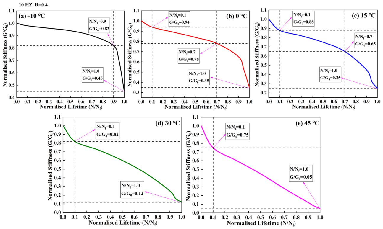
Temperature and shear stress levels exerted a pronounced regulatory effect on the three-stage damage evolution patterns described above. As illustrated in Figure 13, temperature changes fundamentally modified the overall shape of the stiffness degradation curves. At −10 °C and 0 °C, the EEA bond coat was relatively high, resulting in an extremely long duration for Stage II (the stable damage propagation phase), during which the decrease in stiffness was minimal, and failure manifested as a typical brittle fracture (Stage III was extremely short). When the temperature increased to 30 °C and 45 °C, the high-temperature viscous effects of the asphalt phase caused a significant reduction in the material’s resistance to shear deformation. The stiffness degradation curve did not exhibit a distinct plateau phase; Stages I and II merged, and stiffness decreased rapidly in an approximately linear manner with increasing loading cycles until complete interface failure occurred. It can thus be concluded that increasing the loading frequency is equivalent to lowering the ambient temperature, which significantly extends the duration of the stable damage propagation stage. This is consistent with the time-temperature superposition principle for asphalt materials described earlier.
Figure 13.
Stiffness degradation evolution curves at different temperatures: (a) −10 °C; (b) 0 °C; (c) 15 °C; (d) 30 °C; (e) 45 °C.
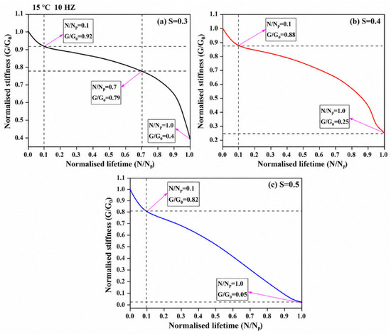
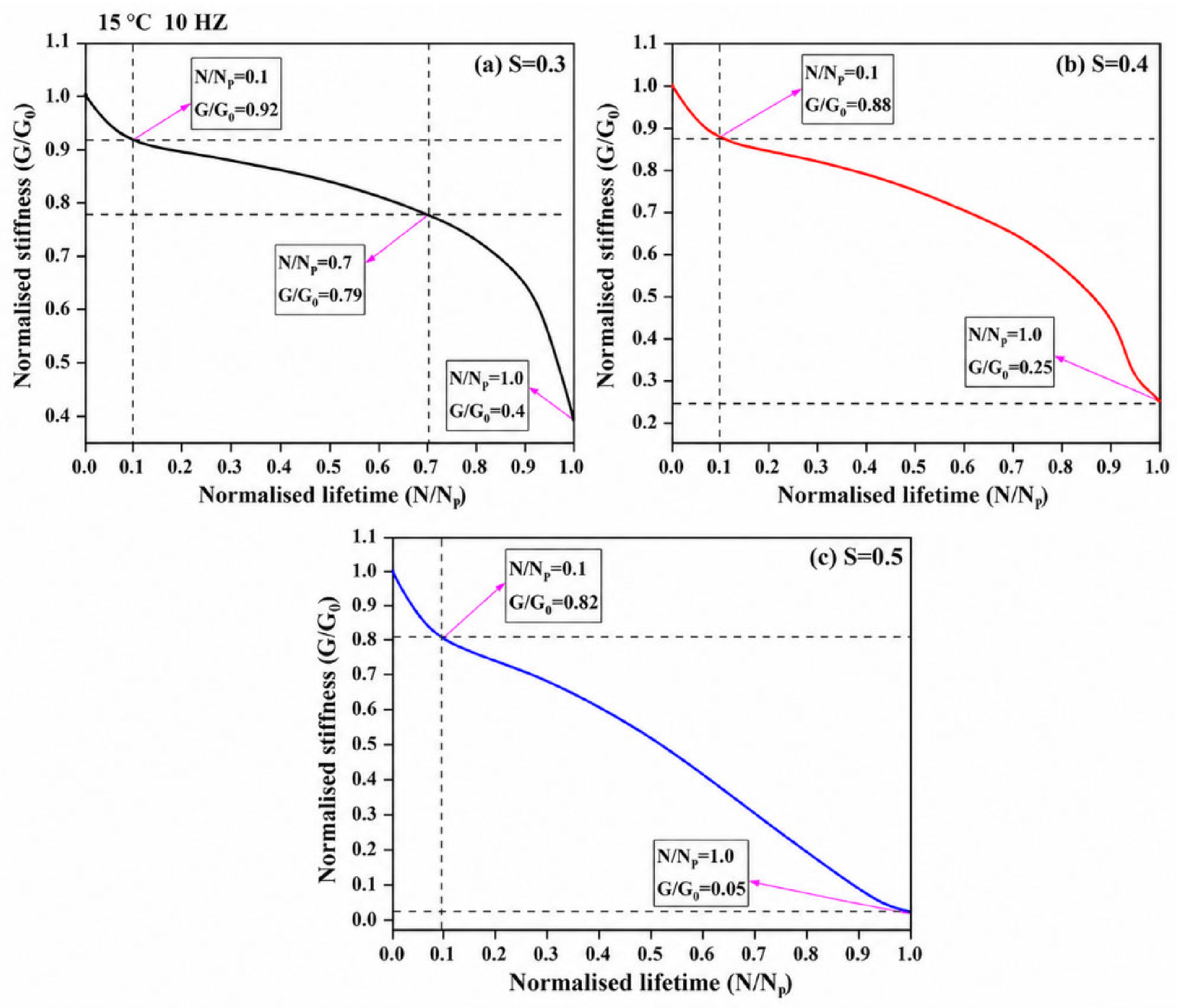
As shown in Figure 14, at a constant temperature of 15 °C, increasing the stress level significantly accelerated the degradation rate of stiffness during the steady-state damage propagation phase. When the stress level R = 0.3, the specimen retained 79% of its initial stiffness after 70% of the fatigue life; whereas when R = 0.5, the remaining stiffness at the same life stage dropped to below 35%. This phenomenon indicates that a high stress level accelerated the fracture of the epoxy resin’s three-dimensional cross-linked network and the debonding at the aggregate-binder interface, causing the rate of fatigue damage accumulation to increase nonlinearly.
Figure 14.
Stiffness degradation evolution curves under different stress levels: (a) S = 0.3; (b) S = 0.4; (c) S = 0.5.
3.4.3. Multifactorial Coupled Shear Fatigue Equations and Service Life Prediction
A multivariable linear regression analysis was conducted on the pooled fatigue test data to develop an interlayer service life prediction model. The phenomenological model takes temperature (T), loading frequency (f) and stress level (S) as input variables. Experimental results confirm a strong linear or log-linear relationship between logNf and all three variables, supporting the adoption of a linear regression framework. The goodness of fit of the model was evaluated using the adjusted coefficient of determination (Adj. R2), root mean square error (RMSE) and p-values of the independent variables. The derived multi-factor fatigue life prediction equation and its estimated coefficients are presented as follows:
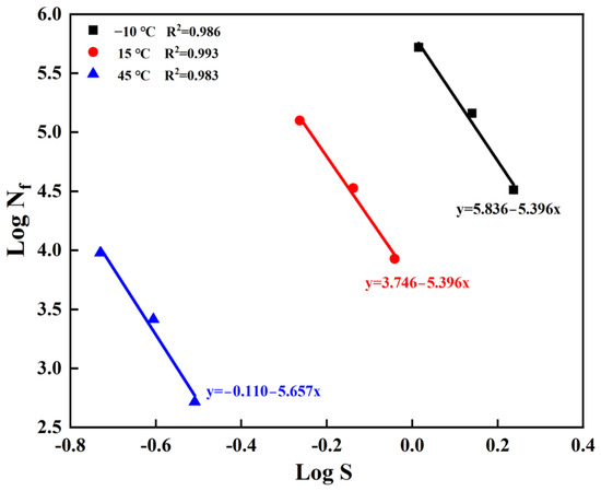
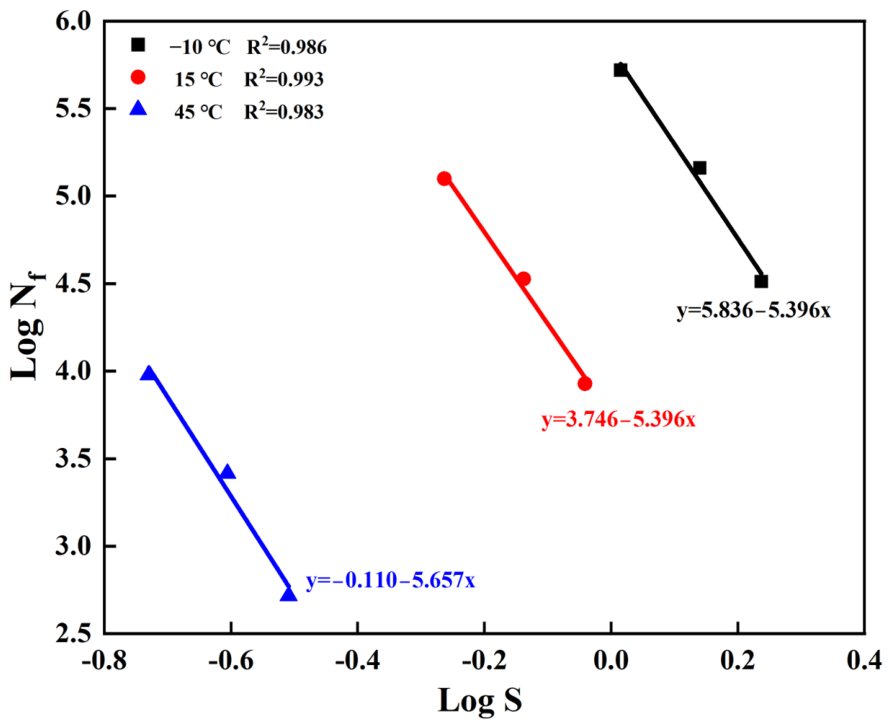
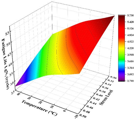
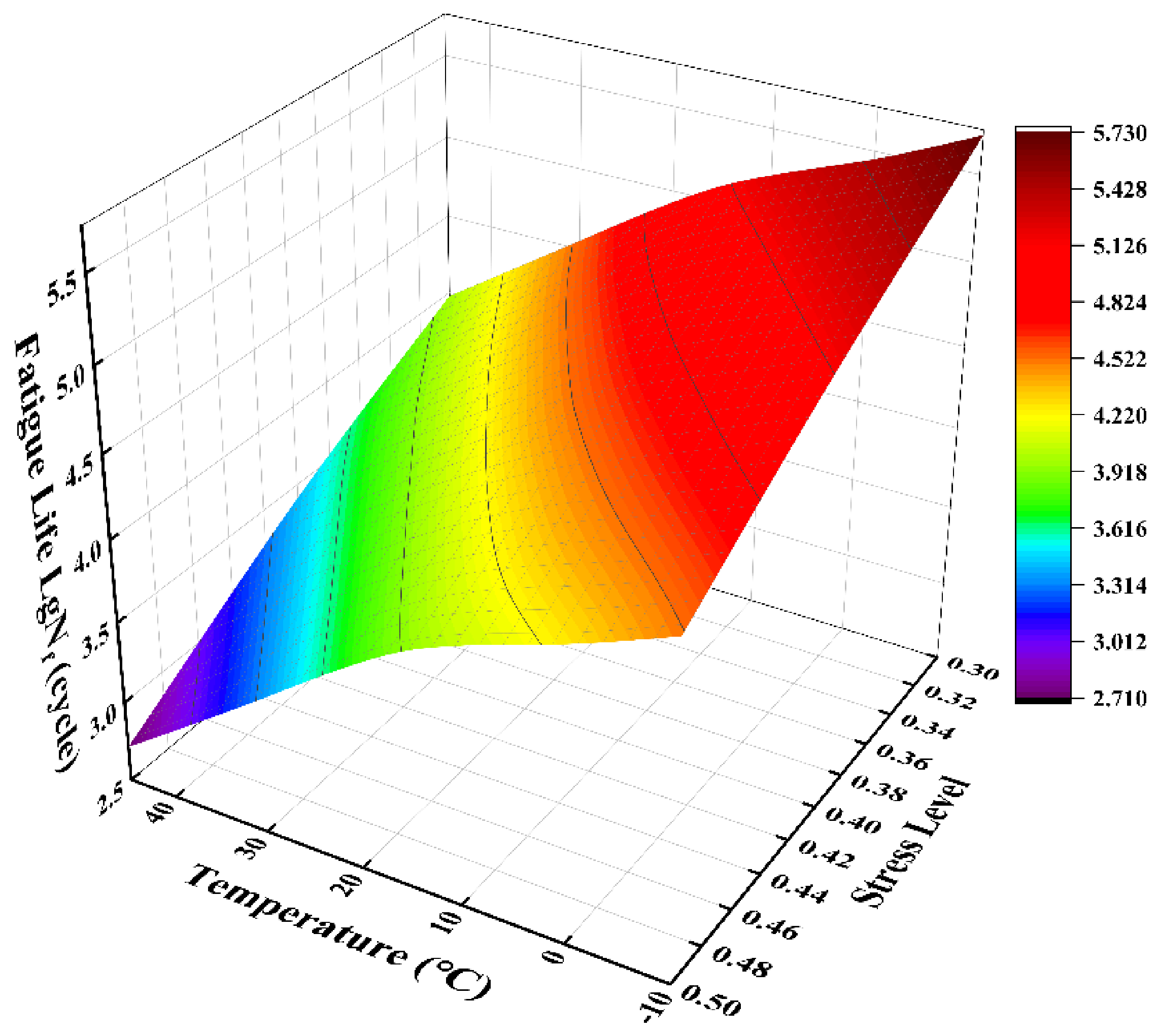
The global regression model achieves strong predictive performance, with an adjusted coefficient of determination (adjusted R2) of 0.985 and a root mean square error (RMSE) of 0.12. All independent variables reach statistical significance (p < 0.01). Figure 15 plots the fitted shear fatigue life equations in a log Nf-log S coordinate system at different test temperatures and a fixed loading frequency of 10 Hz, to highlight the dominant interaction effects between variables. The slopes of the fitted lines increase progressively with rising temperature, indicating pronounced temperature dependence of the fatigue performance of the EEA bond layer. Note that each regression line in Figure 15 is fitted separately for its corresponding temperature subset; thus, the local slopes of the stress variable slightly differ from the global coefficients defined in Equation (3). Figure 16 presents the three-dimensional fatigue life response surface under the coupled effects of temperature and stress level at a constant loading frequency of 10 Hz. Fatigue life peaks in the low-temperature, low-stress region and decays exponentially with increasing temperature and stress level. This trend agrees well with the stiffness degradation behaviour reported earlier, and corroborates the rationality of the underlying damage mechanism.
Figure 15.
Fitted curves of the interlayer shear fatigue life equation for the EEA bond layer in the log Nf-log S coordinate system at representative temperatures and a constant loading frequency of 10 Hz.
Figure 16.
Three-dimensional interlayer shear fatigue life response surface for the EEA bond layer under coupled temperature and stress conditions at a constant loading frequency of 10 Hz.
The multi-factor fatigue life prediction model developed in this work provides a practical reference for the design and maintenance of rigid–flexible composite pavement infrastructure. A material-level calculation framework was established to quantitatively predict the shear fatigue performance of EEA under variable service conditions. With input of local climatic data (temperature) and traffic parameters (loading frequency and stress level), the cumulative interfacial damage process can be estimated. In addition, the material-level test results provide fundamental parameters for macroscopic finite element simulations of pavement fatigue performance. This evaluation framework supports material selection and durability-oriented structural design of rigid–flexible composite tunnel pavements. It can guide design measures to constrain peak interlayer shear stress and mitigate early damage, such as interfacial debonding, under heavy traffic loads.
4. Conclusions
Through this study of the interlayer shear fatigue performance of epoxy-emulsified asphalt (EEA) bond coat under the coupled effects of environmental factors and loads, the following main conclusions were drawn:
(1) EEA bonding agents exhibited excellent bonding performance between cement concrete and asphalt surface layers. Tests determined that the optimal application rate was 0.8 kg/m2, which yielded an interlayer shear strength of 1.72 MPa at 25 °C. Insufficient application prevented the binder from filling the base course’s surface texture, reducing the effective bonding area. Excessive application led to the formation of an overly thick free asphalt film at interlayer bonding systems, causing cohesive failure.
(2) Determining fatigue life using the optimised geometric tangent method can significantly reduce the variability associated with traditional data processing methods and improve the reliability of test results. The interlayer shear fatigue damage evolution of EEA followed a distinct three-stage pattern: the initial damage stage (0–0.1 N/Nf), the stable damage propagation stage (0.1–0.7 N/Nf), and the macroscopic failure stage (0.7–1.0 N/Nf). The sudden drop in stiffness during the initial stage stems from the coupled effects of internal pore compaction and microcrack initiation, which are jointly regulated by temperature and stress levels.
(3) The EEA bond coat exhibits significant temperature and frequency sensitivity, with its mechanical behaviour conforming to the time-temperature superposition principle for asphalt materials. As the temperature increased or the loading frequency decreased, the shear modulus of the bond coat decreased significantly, and the fatigue life decayed exponentially. In low-temperature environments ranging from −10 °C to 0 °C, the specimens exhibited brittle interfacial debonding failure; when the temperature rose above 30 °C, the specimens gradually transitioned to viscoplastic cohesive failure, displaying distinct ductile rheological characteristics.
(4) In a double-logarithmic coordinate system, the interlayer shear fatigue life of the EEA maintains strong linear correlations with stress level, temperature, and loading frequency. The multifactorial coupled fatigue life prediction model developed in this study achieved a high coefficient of determination (R2 > 0.98), demonstrating excellent predictive accuracy. This model comprehensively accounts for the coupled effects of environmental conditions and loading, providing a scientific basis for the interlayer structural design, service life assessment, and maintenance decision-making of rigid–flexible composite pavements.
Author Contributions
Conceptualisation, R.S. and L.K.; methodology, R.S. and J.L.; validation, R.S., J.L. and L.K.; formal analysis, R.S.; investigation, R.S. and J.L.; data curation, R.S.; writing—original draft preparation, R.S.; writing—review and editing, L.K. and J.L.; visualisation, L.K. All authors have read and agreed to the published version of the manuscript.
Funding
This research received no external funding.
Institutional Review Board Statement
Not applicable.
Informed Consent Statement
Not applicable.
Data Availability Statement
Data available on request from the authors. The data that support the findings of this study are available from the corresponding author, Lingyun Kong, upon reasonable request.
Acknowledgments
The authors would like to thank the staff of Chongqing Jiaotong University for their technical support during the experiments. We also appreciate the valuable suggestions from the reviewers, which greatly improved the quality of this manuscript.
Conflicts of Interest
Author Jiyi Li was employed by the company Chongqing Highway Maintenance Engineering (Group) Co., Ltd. The remaining authors declare that the research was conducted in the absence of any commercial or financial relationships that could be construed as potential conflicts of interest.
References
- Su, T.; Wang, T.; Zhang, Z.; Sun, X.; Gong, S.; Mei, X.; Tan, Z.; Cui, S. Mechanical properties and frost resistance of recycled brick aggregate concrete modified by nano-SiO2. Nanotechnol. Rev. 2023, 12, 20230576. [Google Scholar] [CrossRef] [Scilit]
- Su, T.; Wu, J.; Zou, Z.; Yuan, J. Bond performance of steel bar in RAC under salt-frost and repeated loading. ASCE-J. Mater. Civ. Eng. 2020, 32, 04020261. [Google Scholar] [CrossRef] [Scilit]
- Wang, J.; Luo, X.; Huang, X.; Ye, Y.; Ruan, S. Analysis on effects of joint spacing on the performance of jointed plain concrete pavements based on long-term pavement performance database. Materials 2022, 15, 8132. [Google Scholar] [CrossRef] [Scilit] [PubMed]
- Zhang, Y.; Roesler, J.; Dahal, S. Predicting transverse crack properties in continuously reinforced concrete pavement. Constr. Build. Mater. 2023, 364, 129842. [Google Scholar] [CrossRef] [Scilit]
- Cho, Y.-H. Asphalt Overlay Design Methods for Rigid Pavements Considering Rutting, Reflection Cracking, and Fatigue Cracking; The University of Texas at Austin: Austin, TX, USA, 1995. [Google Scholar]
- Halil, C.; Mathews, R.; Kota, T.; Gopalakrishnan, K.; Coree, B. Rehabilitation of Concrete Pavements Utilising Rubblization and Crack and Seat Methods. CTRE Project 02-106. 2005. Available online: https://ctre.iastate.edu/wp-content/uploads/2018/03/rubblization-1.pdf (accessed on 22 June 2026).
- Li, S.; Liu, Z. Study on crack extension of the AC layer of CRC+ AC composite pavement. Mechanics 2012, 18, 141–147. [Google Scholar] [CrossRef] [Scilit]
- Li, S.; Liu, Z.-H.; Li, Y.-Z. Influence of structure layer thickness of CRC+ AC composite pavement on temperature effect and rutting deformation. Zhongguo Gonglu Xuebao (China J. Highw. Transp.) 2012, 25, 21–28. [Google Scholar]
- Al-Qadi, I.L.; Wang, H. Evaluation of Pavement Damage Due to New Tyre Designs; FHWA-ICT-09-048; Illinois Center for Transportation (ICT): Rantoul, IL, USA, 2009. [Google Scholar]
- Alae, M.; Zhao, Y.; Zarei, S.; Fu, G.; Cao, D. Effects of layer interface conditions on top-down fatigue cracking of asphalt pavements. Int. J. Pavement Eng. 2020, 21, 280–288. [Google Scholar]
- Chen, S.; Chi, M.; Shen, Z.; Yao, Y.; Gao, F. Reinforcement of interlaminar mechanical properties between rigid and flexible layers of semi-rigid base asphalt pavement using interlayer treatment. Int. J. Pavement Eng. 2023, 24, 2111565. [Google Scholar]
- Collop, A.; Sutanto, M.; Airey, G.; Elliott, R. Shear bond strength between asphalt layers for laboratory-prepared samples and field cores. Constr. Build. Mater. 2009, 23, 2251–2258. [Google Scholar] [CrossRef] [Scilit]
- Raposeiras, A.C.; Vega-Zamanillo, Á.; Calzada-Pérez, M.Á.; Castro-Fresno, D. Influence of surface macro-texture and binder dosage on the adhesion between bituminous pavement layers. Constr. Build. Mater. 2012, 28, 187–192. [Google Scholar] [CrossRef] [Scilit]
- Salinas, A.; Al-Qadi, I.L.; Hasiba, K.I.; Ozer, H.; Leng, Z.; Parish, D.C. Interface layer tack coat optimization. Transp. Res. Rec. 2013, 2372, 53–60. [Google Scholar] [CrossRef] [Scilit]
- Guedes, R.M. Creep and Fatigue in Polymer Matrix Composites; Woodhead Publishing: Cambridge, UK, 2019. [Google Scholar]
- Liu, Z.; Yu, S.; Huang, Y.; Liu, L.; Pan, Y. A systematic review of rigid-flexible composite pavement. J. Road Eng. 2024, 4, 203–223. [Google Scholar] [CrossRef] [Scilit]
- Tozzo, C.; Fiore, N.; D’Andrea, A. Dynamic shear tests for the evaluation of the effect of the normal load on the interface fatigue resistance. Constr. Build. Mater. 2014, 61, 200–205. [Google Scholar] [CrossRef] [Scilit]
- Walubita, L.F.; Fuentes, L.; Lee, S.I.; Dawd, I.; Mahmoud, E. Comparative evaluation of five HMA rutting-related laboratory test methods relative to field performance data: DM, FN, RLPD, SPST, and HWTT. Constr. Build. Mater. 2019, 215, 737–753. [Google Scholar] [CrossRef] [Scilit]
- Wang, X.; Su, Z.; Xu, A.; Zhou, A.; Zhang, H. Shear fatigue between asphalt pavement layers and its application in design. Constr. Build. Mater. 2017, 135, 297–305. [Google Scholar] [CrossRef] [Scilit]
- Chen, Y.; Hossiney, N.; Yang, X.; Wang, H.; You, Z. Application of Epoxy-Asphalt Composite in Asphalt Paving Industry: A Review with Emphasis on Physicochemical Properties and Pavement Performances. Adv. Mater. Sci. Eng. 2021, 2021, 3454029. [Google Scholar] [CrossRef] [Scilit]
- Kong, L.; Su, S.; Wang, Z.; Wu, P.; Zhang, Y.; Chen, Z.; Ren, D.; Ai, C. Microscale mechanism and key factors of waterborne epoxy resin emulsified asphalt enhancing interlayer bonding performance and shear resistance of bridge deck pavement. Constr. Build. Mater. 2024, 419, 135570. [Google Scholar] [CrossRef] [Scilit]
- Liu, S.; Zhou, M.; Dai, Y.; Wu, C.; Zhang, H. Interlayer Bonding Performance of Waterborne Epoxy Emulsified Asphalt Ultra-thin Wearing Course. J. Highw. Transp. Res. Dev. 2024, 41, 66–77. (In Chinese) [Google Scholar]
- Liu, L.; Keller, T.; Movahedi-Rad, A.V. The effects of stress ratio and temperature on fatigue behaviour of an epoxy adhesive. Int. J. Fatigue 2026, 205, 109401. [Google Scholar] [CrossRef] [Scilit]
- Chang, Y.; Chen, Z.; Niu, X.; Zhou, Z. Test of Shear Resistance of Modified Emulsified Asphalt by Waterborne Epoxy Resin. J. Jiangsu Univ. (Nat. Sci. Ed.)/Jiangsu Daxue Xuebao (Ziran Kexue Ban) 2017, 38, 224–229. (In Chinese) [Google Scholar] [CrossRef]
- Wang, Y.; Qu, C.; Zhu, C.; Liu, Z.; Jiang, Y.; Huang, Y.; Bao, S. Influence of Stress Absorbing Layer Materials on Interlaminar Shear Performance of Asphalt Pavement Overlay Structure. Hans J. Civ. Eng. 2026, 15, 258. (In Chinese) [Google Scholar]
- Li, S.; Liu, X.; Liu, Z. Interlaminar shear fatigue and damage characteristics of asphalt layer for asphalt overlay on rigid pavement. Constr. Build. Mater. 2014, 68, 341–347. [Google Scholar] [CrossRef] [Scilit]
- Rahman, A.; Huang, H.; Ai, C.; Ding, H.; Xin, C.; Lu, Y. Fatigue performance of interface bonding between asphalt pavement layers using a four-point shear test setup. Int. J. Fatigue 2019, 121, 181–190. [Google Scholar] [CrossRef] [Scilit]
- Cao, M.; Huang, W.; Lu, Y.; Wu, M.; Li, Y. Experimental and Evaluation Methods for Interlayer Shear Performance of Composite Pavements. J. Highw. Transp. Res. Dev. 2018, 35, 40–48. (In Chinese) [Google Scholar]
- Nian, T.; Ge, J.; Li, P.; Guo, R.; Liu, W. Influence of multiple factors on the shear fatigue resistance of asphalt pavement interlayer adhesive materials. J. Mater. Civ. Eng. 2020, 32, 04020251. [Google Scholar] [CrossRef] [Scilit]
- Yang, K.; Li, R.; Yu, Y.; Pei, J.; Liu, T. Evaluation of interlayer stability in asphalt pavements based on shear fatigue property. Constr. Build. Mater. 2020, 258, 119628. [Google Scholar] [CrossRef] [Scilit]
- Ragni, D.; Sudarsanan, N.; Canestrari, F.; Kim, Y.R. Investigation into fatigue life of interface bond between asphalt concrete layers. Int. J. Pavement Eng. 2022, 23, 3371–3385. [Google Scholar]
- West, R. Evaluation of Bond Strength Between Pavement Layers; NCAT report; NCAT: Auburn, AL, USA, 2005.
- Lv, S.; Wang, Z.; Zhu, X.; Yuan, J.; Peng, X. Research on strength and fatigue properties of asphalt mixture with different gradation curves. Constr. Build. Mater. 2023, 364, 129872. [Google Scholar] [CrossRef] [Scilit]
- Rys, D.; Szydlowski, C. Consideration of pseudo strain energy in determination of fatigue life and microdamage healing of asphalt mastics. Int. J. Fatigue 2024, 181, 108164. [Google Scholar] [CrossRef] [Scilit]
- Bjørheim, F.; Pavlou, D.G.; Siriwardane, S.C. Nonlinear fatigue life prediction model based on the theory of the S-N fatigue damage envelope. Fatigue Fract. Eng. Mater. Struct. 2022, 45, 1480–1493. [Google Scholar] [CrossRef] [Scilit]
- Jin, T.; Liu, L.; Yang, R.; Sun, L.; Yuan, J. Investigation of interlayer bonding performance between asphalt concrete overlay and Portland cement concrete using inclined shear fatigue test. Constr. Build. Mater. 2023, 400, 132681. [Google Scholar] [CrossRef] [Scilit]
- Silva, M.P.S.; Correia, N.S. Cyclic shear behaviour of geosynthetic pavement interlayers in asphalt systems. Constr. Build. Mater. 2026, 528, 146547. [Google Scholar] [CrossRef] [Scilit]
- Jia, X.; Huang, B. Characterisation of shear resistance of interlayer between concrete bridge deck and asphalt concrete overlay utilising inclination shear test. J. Mater. Civ. Eng. 2022, 34, 04021424. [Google Scholar] [CrossRef] [Scilit]
- Huang, Y.; Su, S.; Yang, H.; Rahman, A.; Ai, C. Novel Oblique Shear Test Method and Quantitative Evaluation of Fatigue Shear Resistance between Asphalt Pavement Layers under Comprehensive Pavement Working Conditions. J. Mater. Civ. Eng. 2025, 37, 04025204. [Google Scholar] [CrossRef] [Scilit]
- Xu, Y.; Lv, X.; Ma, C.; Liang, F.; Qi, J.; Chou, Z.; Xu, S. Shear fatigue performance of epoxy resin waterproof adhesive layer on steel bridge deck pavement. Front. Mater. 2021, 7, 618073. [Google Scholar] [CrossRef] [Scilit]
- Zheng, W.; Nian, T.; Wang, G.; Wei, Z.; Liu, Z.; Liu, W. Investigation on Influencing Factors of Interlayer Shear Fatigue Resistance of Asphalt Mixtures Based on Grey Entropy Theor. J. Lanzhou Univ. Technol. 2023, 49, 138. (In Chinese) [Google Scholar]
- Cheng, H.; Sun, L.; Wang, Y.; Chen, X. Effects of actual loading waveforms on the fatigue behaviours of asphalt mixtures. Int. J. Fatigue 2021, 151, 106386. [Google Scholar] [CrossRef] [Scilit]
- Diakhaté, M.; Millien, A.; Petit, C.; Phelipot-Mardelé, A.; Pouteau, B. Experimental investigation of tack coat fatigue performance: Towards an improved lifetime assessment of pavement structure interfaces. Constr. Build. Mater. 2011, 25, 1123–1133. [Google Scholar] [CrossRef] [Scilit]
- Wang, J.; Gao, S.; Dong, S.; Tian, J. Review on Experimental Characterisation of Fatigue Damage in Asphalt Mixtures. Sci. Technol. Eng. 2024, 24, 2625–2637. (In Chinese) [Google Scholar] [CrossRef]
- Wang, C.; Sun, Y.; Ren, Z. Discrimination of Behavioural Characteristics of Asphalt Fatigue Crack Initiation and Propagation Under Dynamic Shear Loading. J. Beijing Univ. Technol. 2026, 52, 282–293. (In Chinese) [Google Scholar] [CrossRef]
- Yang, K.; Li, R.; Yu, Y.; Pei, J. Unified laboratorial evaluation of interlayer bond property in asphalt pavements based on strength parameters. Constr. Build. Mater. 2021, 273, 121738. [Google Scholar] [CrossRef] [Scilit]
- Xie, Y.; Han, D.; Pan, Y.; Tang, D.; Zhao, Y. Multiscale Analysis of Epoxy Asphalt Performance Based on Formulation and Curing Parameters. J. Mater. Civ. Eng. 2010, 37, 17. [Google Scholar]

Disclaimer/Publisher’s Note: The statements, opinions and data contained in all publications are solely those of the individual author(s) and contributor(s) and not of MDPI and/or the editor(s). MDPI and/or the editor(s) disclaim responsibility for any injury to people or property resulting from any ideas, methods, instructions or products referred to in the content. |
© 2026 by the authors. Licensee MDPI, Basel, Switzerland. This article is an open access article distributed under the terms and conditions of the Creative Commons Attribution (CC BY) license.