


Highlights
What are the main findings?
- Appropriate CeO2 addition effectively inhibits microcrack generation of laser-clad Fe60 coatings on ZGMn13 high manganese steel, while low CeO2 content (1 wt%) causes obvious coating fracture defects.
- The 2 wt% CeO2-modified coating achieves the optimal microstructure with fine and dense grains, and exhibits the highest microhardness, which is 2.53 times that of the high manganese steel substrate.
- The 2 wt% CeO2-doped composite coating obtains the minimum wear rate, which is 78.6% lower than the untreated substrate, and presents a mixed abrasive-adhesive wear mechanism.
What are the implications of the main findings?
- This work solves the inherent cracking problem of traditional ceramic-reinforced cladding coatings on high manganese steel under impact load via low-concentration rare earth CeO2 modification.
- The optimal CeO2 doping concentration and internal grain refinement and wear resistance enhancement mechanism are clarified, providing clear parameter guidance for laser cladding surface modification of high manganese steel.
- The proposed laser cladding modification strategy significantly improves the surface hardness and wear resistance of jaw crusher jaw plates, offering reliable technical support for prolonging the service life of heavy crushing equipment components.
Abstract
High manganese steel jaw plates serve as the core structural components of jaw crushers. Subjected to continuous impact and compressive loads during crushing service, they demand superior wear resistance and impact fatigue performance. In this work, laser cladding was employed to fabricate CeO2-reinforced Fe60 composite coatings on ZGMn13 high manganese steel jaw plate substrate. The surface modification effects were systematically investigated in terms of macroscopic structure analysis, hardness property testing, and wear resistance evaluation. Composite coatings with CeO2 mass fractions of 0%, 1%, 2%, and 3% were prepared, and their microstructures and morphologies were characterized by visual inspection, optical microscopy, and scanning electron microscopy. The test results indicate that the dendritic structures became more pronounced with increasing CeO2 content; however, fracture marks occurred when the CeO2 content was below 1%. A Rockwell hardness tester was adopted to measure coating hardness under a load stress of 382.44 MPa, and the results demonstrate that coating hardness presents a positive correlation with CeO2 doping content. Furthermore, pin-on-disc friction and wear tests were conducted on the prepared coatings. The optimized CeO2-modified coating achieved a minimum wear rate of 0.0033 mm3/(N·m), which is 78.6% lower than that of the untreated substrate. This work provides a valuable reference for improving the surface hardness and wear resistance of jaw plates and promotes the engineering application of laser cladding technology in wear-resistant component strengthening.
1. Introduction
The jaw plate is a key component of the jaw crusher that is in direct contact with materials. It is continuously subjected to substantial impact and extrusion during the crushing process, posing significant challenges to its surface wear resistance and impact fatigue performance [1]. Although laser cladding technology has been widely studied, scant attention has been directed toward its use in improving the structural hardness and operational strength of crushers.
Laser cladding is an advanced surface engineering technique that uses a high-energy directional laser beam to melt the cladding material and a thin layer on the surface of the substrate synchronously to form a local metallurgical molten pool. Upon rapid solidification, a robust “coating-transition zone-substrate” interface is formed, thus avoiding overheating of the substrate in deep layers [2]. The process outcome is governed by a complex interplay of parameters, such as cladding material, substrate, laser, and ambient environment, which all influence the formation, solidification, and interfacial bonding of the molten pool [3]. Critical factors include feedstock composition, material morphology, and feed rate, which are employed to intervene in energy conversion by altering the melting threshold, melt mobility, and material supply balance; these factors in turn dynamically modulate the compositional homogeneity of the molten pool, the melting state, and the microstructure and properties of the coating [4]. Substrate-related parameters, such as substrate flatness and triaxial displacement, regulate the uniformity of laser energy distribution and the precision of the action position to intervene in the stability of the energy transfer, thereby influencing the consistency of the molten pool morphology, the uniformity of the interfacial bonding, and the dimensional accuracy of the coating [5]. Similarly, laser intensity, temporal attributes (e.g., pulse duration), and wavelength determine the input energy and absorption efficiency, thereby dynamically regulating the temperature field, flow state, and solidification rate of the molten pool, as well as the coating quality [6]. Furthermore, ambient atmosphere conditions (e.g., oxygen content) and humidity affect the oxidation behaviour and porosity formation probability, which in turn influence the defect incidence and coating densification [7].
Owing to its multi-parameter tunability for precision processing and universal applicability in forming high-performance metallurgical bonds, laser cladding remains a prominent research focus in surface modification. Laser cladding technology enables targeted optimization by allowing precise control over the material composition and microstructure of the coating. This capability can be leveraged to tailor the jaw plate for high-impact abrasive wear conditions, thereby enhancing its wear resistance. There are many studies on the optimization of laser power, spot diameter, working draft, and other laser cladding parameters. For instance, Ainhoa Riquelme et al. [8] analyzed and optimized the process parameters of laser composite coating with ZE41 magnesium alloy as the substrate and Al-SiCp as the fusion cladding material; it was found that a laser power of 650 W, a scanning speed of 17 mm/s, and a single-pass working mode were optimal. Laser fusion cladding with Al2O3-SiC was shown to improve the quality of the fused cladding layer on lightweight armour material, with results suggesting that achieving high quality of the fused cladding layer requires a precise balance of processing parameters [9]. Xiao Q. et al. [10] optimized laser cladding process parameters and achieved a 30% promotion of comprehensive coating quality on the basis of existing 40% performance optimization schemes. The influence of temperature and other process parameters on the laser cladding layer was systematically examined through an integrated numerical and experimental methodology, with the aim of enhancing process quality and efficiency.
Laser cladding technology enhances the bonding strength, abrasion resistance, corrosion resistance, and oxidation resistance of the coating by adjusting laser, process parameters, and spot diameter. Additionally, it reduces defects such as porosity and cracks, thereby improving the coating quality. The development of new materials broadens the scope of aerospace, automotive manufacturing, machining, and other fields, offering strong environmental friendliness, low power consumption, low waste emission, and sustainable development.
The optimization of the material composition of laser cladding coatings is essential for achieving grain homogenization, microscopic refinement, and compositing. This is accomplished by modulating the microstructure, component distribution, and phase composition, which in turn enhances target properties such as hardness and wear resistance [11]. For example, Chu Y. et al. [12] investigated the influence of the rare-earth oxide CeO2 on the microstructure and properties of AlCoCrFeNi laser cladding coating. Their analysis encompassed the macro-morphology, microstructure (grain size, phase composition), hardness, friction coefficient, and corrosion resistance of the coatings with CeO2 addition levels ranging from 0% to 3%. They found that the addition of 3% CeO2 yielded the most significant grain refinement, resulting in superior integrated mechanical properties, including a high hardness of 426 HV0.5 and a low friction coefficient of 0.62. In contrast, the coating with 2% CeO2 exhibited optimal corrosion resistance, as evidenced by its minimal self-corrosion current density of 5.661 × 10⁻⁷ A·cm−2, indicating that a composition of 2%–3% CeO2 effectively enhances the AlCoCrFeNi2 coating properties. However, most of these studies focus on high-entropy alloys or aluminum/magnesium alloys; systematic investigations on the use of CeO2-modified laser cladding for ZGMn13 high manganese steel jaw plates—in particular, the optimum CeO2 addition level, crack control, and wear mechanisms under the specific impact-abrasion conditions of jaw crushers—remain scarce.
As a typical rare-earth oxide, CeO2 features a high melting point, stable chemical properties, unique grain refinement, and molten pool purification capacity, which differ from rigid ceramic reinforcing phases such as Al2O3, SiC and WC. Hard ceramic particles easily induce interfacial stress concentration and microcracks under cyclic impact loads; in contrast, low-content CeO2 can optimize molten metal fluidity, refine grains and suppress crack propagation. The effective modification range of CeO2 in Fe-based cladding coatings is 1–3 wt%, and excessive doping (≥4 wt%) will cause severe rare-earth agglomeration, element segregation and coating brittleness. This study selects 1%, 2%, and 3 wt% CeO2 as research variables to explore the optimal doping proportion.
Although Hadfield ZGMn13 high manganese steel has been widely applied for decades, its inherent defects of low surface hardness and poor impact-abrasion resistance severely shorten the service life of jaw crusher jaw plates. Existing research mainly focuses on bulk modification of high manganese steel or single laser parameter optimization, while systematic research on rare-earth CeO2-modified Fe60 laser cladding coatings tailored for jaw plate impact wear conditions is still insufficient.
Therefore, this paper focuses on the macroscopic structure, hardness, and wear performance of CeO2-modified claddings on jaw plates. The results are expected to provide a reference for enhancing the surface hardness and wear resistance of jaw plates, thereby advancing laser cladding-based surface treatment techniques for heavy-duty industrial applications.
2. Materials and Equipment
2.1. Substrate and Cladding Materials
In this study, commonly used high manganese steel (grade ZGMn13 as elemental composition showed in Table 1) for crusher jaws was selected as the substrate for laser cladding, with a carbon (C) content of 1.20%. Fe60 alloy powder, provided by Qinghe County Cast Gold Welding Materials Co., Ltd. (Xingtai, China), was used as the cladding material. The powder had a particle size of 45~106 µm, and its elemental composition is shown in Table 1. The CeO2 rare-earth powder adopted in this experiment was purchased from Zhongnuo New Material Technology Co., Ltd. (Dezhou, China), with an initial particle size of 15–20 μm. The CeO2 powder was weighed and mixed with Fe60 alloy powder according to mass fractions of 1%, 2% and 3% for subsequent ball milling treatment.
Table 1.
Chemical components of ZGMn13 and Fe60 alloy powder.
2.2. Laser Cladding Equipment
The QM-3SP4 planetary ball mill, manufactured by Nanjing Laibu Technology Industry Co., Ltd., Nanjing, China, was used in this study. The stainless steel ball mill jars have a specification of 400 mL, with a feed size of ≤ 10 mm and a discharge size as small as 0.1 µm. The rated speed of the large disc is 265 rpm ± 10%, and the rotation speed of the ball mill jar is 530 rpm ± 10%. The mill is equipped with five operating modes: unidirectional operation, timer shutdown, variable speed operation, forward and reverse alternate operation, and unidirectional interval operation.
The DZF-6090 vacuum drying oven supplied by Shanghai Yiheng Technology Co., Ltd., Shanghai, China, was utilized in this study, with key specifications including a volume of 90 L, inner dimensions of 450 × 450 × 450 mm, outer dimensions of 595 × 600 × 1245 mm, a temperature control range of RT + 10 °C~250 °C, a temperature resolution of 0.1 °C, a constant temperature fluctuation of ≤±0.5 °C, and an internal vacuum degree of <133 Pa.
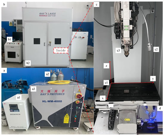
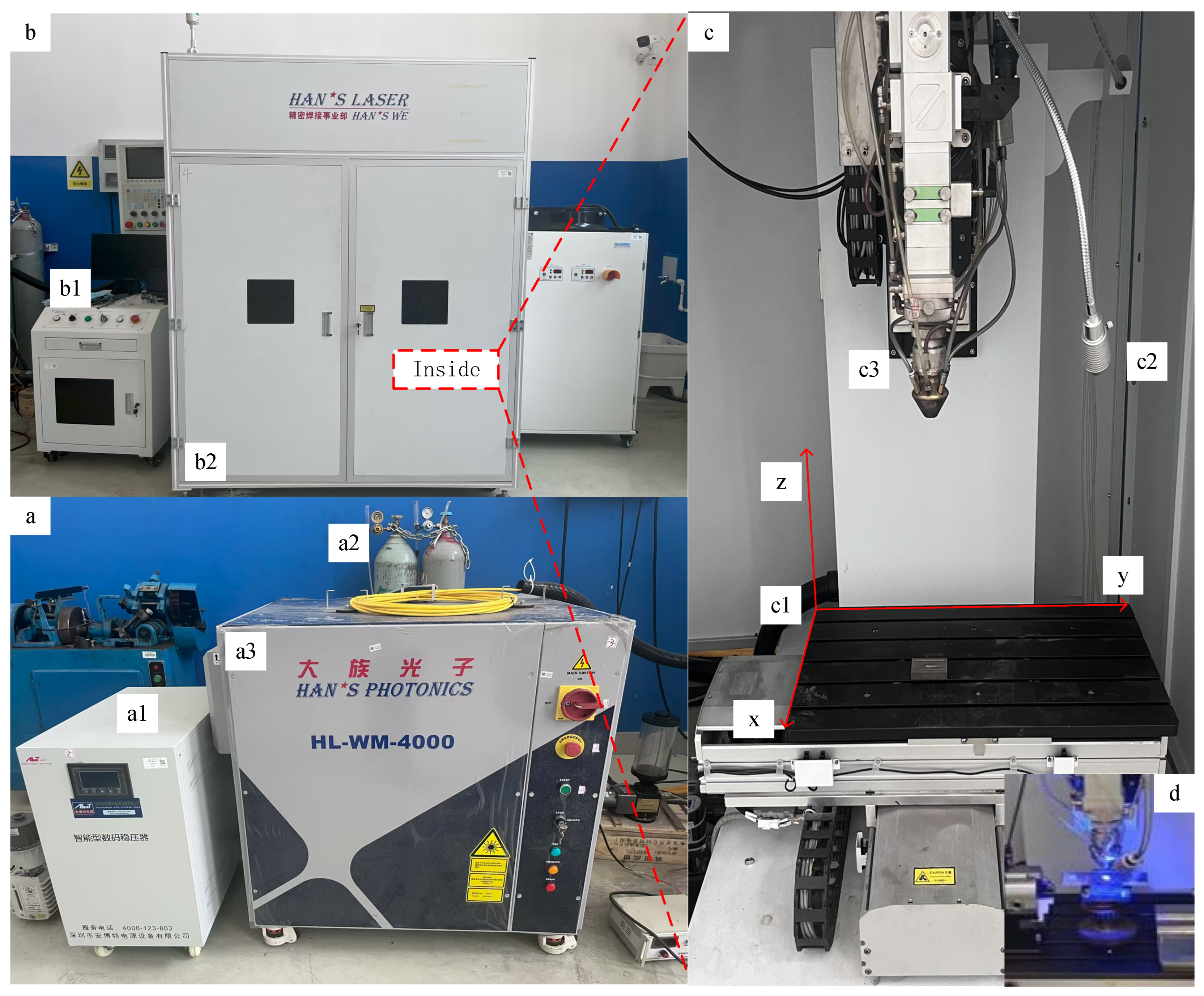
The laser cladding equipment produced by Laser Technology Industrial Group Co., Ltd., Shenzhen, China, consists of an HL-WM-4000 laser cladding machine, a cooler, a powder feeder, a voltage regulator, pure argon shielding gas, and a computer control system. Its main components and their functions are as follows: a high-energy-density laser (4000 W fibre-coupled output semiconductor, Han’s Laser Technology Industry Group Co., Ltd., Shenzhen, China) for emitting laser beams, HUST CNC machine tools for controlling the trajectory of the laser cladding head, and a refrigeration unit for equipment cooling. Additional key components include pure argon shielding gas for cladding process protection, a coaxial powder feeder for cladding powder delivery, a voltage regulator for stabilizing the system’s electrical power supply, and a computer control system for editing cladding parameters. The overall configuration of the equipment, including the computer control system, is shown in Figure 1.
Figure 1.
The laser cladding system. (a) System voltage regulator (a1), argon (Ar) gas (a2), and laser light source (a3). (b) Control unit (b1) and protective housing (b2). (c) Laser cladding CNC platform (c1), powder feeder (c2), and laser cladding head (c3). (d) The laser cladding working process.
2.3. Structural Organization Observation Equipment
The structural characterization equipment used in this study includes an MR2100 metallurgical microscope (Ningbo Yongxin Optical Co., Ltd., Ningbo, China) and an SU8010 scanning electron microscope (Hitachi High-Tech Corporation, Tokyo, Japan). The MR2100 metallurgical microscope has a magnification range of 50–1000×, an image resolution of 300 M, a focusing stroke of 8 mm, a focusing resolution of 0.002 mm, a stage size of 180 mm × 155 mm, and a maximum imaging range of 40 mm × 30 mm.
The SU8010 scanning electron microscope features a magnification range of 100–800,000×, an image resolution of 5120 × 3480, and is equipped with both automatic and manual focusing functions. Its working distance ranges from 1.5 to 30 mm. The 5-axis sample stage has the following specifications: the X-axis moving range is 0–50 mm, the Y-axis 0–50 mm, the Z-axis 1.5–30.0 mm, the tilt angle θ is −5–70°, the rotation angle φ is 360°, and the maximum sample size is 100 mm.
2.4. Phase Structure Testing Equipment
The phase structure of CeO2-modified Fe60 laser cladding coatings on ZGMn13 substrate was characterized using a Rigaku Ultima IV diffractometer (Rigaku Corporation, Tokyo, Japan) equipped with a one-dimensional D/teX-Ultra high-speed array detector. The X-ray generator has a maximum output power of 3.0 kW. A computer controls the tube voltage, tube current start-up, adjustment, and shutdown, with a stability of ±0.01% (against a ±10% fluctuation of the external circuit). The instrument features a Cu target and a ceramic-based composite X-ray tube. Its full-load power is 2.0 kW, with two left and right shutters; the rated current ranges from 2 to 60 mA, and the rated voltage ranges from 20 to 60 kV. The scanning mode is vertical, with 2θ available in either linked vertical mode or independent single-axis vertical mode. The instrument adopts high-precision triple optical encoding, with a minimum angle step of 1/10,000° and a setting repeatability of 1/10,000°. The 2θ scanning range spans from −3° to 162°, with the conventional 2θ scanning starting at 0.3°.
2.5. Hardness Testing Equipment
The microhardness of the samples was measured using an HMV-10S Vickers microhardness tester (Shimadzu Corporation, Kyoto, Japan). The instrument is equipped with a diamond Vickers indenter (with an included angle of 136°) and a motorized XY stage with a travel distance of 25 mm in each direction. Hardness impressions were observed and measured with a 40× objective lens, which provides an effective measurement range of 250 μm and a reading resolution of 0.01 μm.
2.6. Abrasion Test Equipment for Laser Cladding Layers
The DPT-5 penetrant kit, manufactured by Shanghai Xinmeda Flaw Detection Equipment Co., Ltd., Shanghai, China, was utilized for surface crack detection. The complete kit consists of 1 can of penetrant, 2 cans of developer, and 3 cans of cleaner, all packaged in 500 mL spray cans. The key performance parameters are as follows: the penetrant sensitivity is ≤0.5 μm, the developer spreading capacity is 1.2 mL, and the developed film thickness ranges from 0.05 to 0.07 mm.
The HSR-2M high-speed reciprocating friction and wear tester, manufactured by Lanzhou Zhongke Kaihua Science and Technology Development Co., Ltd., Lanzhou, China, features a test force range of 30–1000 g (weight loading) and 10–200 N (automatic loading), with an accuracy of 0.2% F.S. The reciprocating sliding frequency is adjustable from 0.1 to 45 Hz, and the stroke length ranges from 0.5 to 25 mm. The X-axis and Z-axis provide travelling distances of 0–40 mm and 0–150 mm, respectively. The size of the lower specimen ranges from Φ5 to Φ60 mm, with a maximum dimension of 80 × 80 mm.
The MFT-5000 multi-functional friction and wear tester (RTEC Instruments, San Jose, CA, USA) was utilized in this study. This instrument is equipped with an interchangeable evaluation system compatible with various test modules, including rotating, reciprocating, ring block, micro-movement, and scratch tests modules. Key performance parameters are as follows: the rotational testing speed ranges from 0.001 to 10,000 RPM, and the micro-travelling stroke ranges from 5 µm to 5 mm at a maximum frequency of 300 Hz.
The surface morphology of the samples was characterized using a KEYENCE VHX-7000 super depth-of-field microscope (KEYENCE Corporation, Osaka, Japan). The system was configured with a standard VHX-7020 camera featuring a 1/1.8-type CMOS sensor with a resolution of 2064 × 1554 pixels.
3. Methods
3.1. Laser Cladding Process
Pretreatment of cladding materials: Fe60 alloy powder and CeO2 rare-earth powder were accurately weighed according to preset mass ratios of 1%, 2% and 3% CeO2. The mixed powders were transferred to stainless steel ball milling tanks, with a powder-to-grinding-ball mass ratio fixed at 1:5. To prevent powder oxidation during the ball milling process, high-purity argon was filled into the tank as shielding atmosphere. The QM-3SP4 planetary ball mill was employed, operating at a rotational speed of 150 r/min for 2 h to achieve uniform powder mixing via the mill’s grinding and mixing effect. After ball milling, composite powders were placed in a DZF-6090 vacuum drying oven and dried for 2 h to completely remove internal moisture, avoiding powder feeding blockage caused by moisture absorption.
Substrate pretreatment: Due to the presence of grinding debris, paint films, and adherents on the surface of the high manganese steel (ZGMn13) substrate, the surface was first ground using a grinding and polishing machine with 300-mesh sandpaper until no visible sanding marks remained. Subsequently, fine grinding was conducted with 1200-grit sandpaper to achieve a flat and smooth surface. Afterward, the substrate was immersed in anhydrous ethanol for ultrasonic cleaning (to enhance decontamination effect) and then wiped dry with a clean lint-free cotton cloth to ensure surface cleanliness. Finally, the substrate was placed in a drying oven for 3 h to remove residual ethanol and moisture.
Laser cladding: Prior to the experiment, the chiller, voltage regulator, gas system, and computer control system were activated 15 min in advance for preheating, ensuring the entire system operated stably. Subsequently, the laser transmitter was reset to its initial working position, and the pre-edited running trajectory and laser process parameters were imported to start the system. During the cladding process, different cladding paths were realized by controlling the movement of the laser transmitter. Argon gas delivered the powder from the powder feeder to the laser cladding head; under the action of the laser beam, the powder was melted and rapidly solidified on the substrate surface, ultimately forming the CeO2-modified Fe60 cladding layer.
Post-processing of laser cladding: After the completion of the laser cladding experiment, the cladding layer was cut into test specimens with dimensions of 8 mm × 8 mm × 6 mm using a wire electrical discharge machine (WEDM). The cross-section perpendicular to the coating’s scanning direction was ground stepwise with 600, 1200, 1500, and 2000 mesh sandpapers, followed by final polishing with 3000-mesh abrasive paste on a grinding and polishing machine. After polishing, to reveal the internal microstructure of the cladding layer, the polished surface was etched with aqua regia for 45 s. The surface roughness of the polished substrate is Ra6.3–12.5 μm. Immediately after etching, the residual etchant was rinsed off with double-distilled water, and the specimen was dried with cold air or a lint-free cotton cloth.
3.2. Apparent Organization Testing and Analysis
The microstructure of the specimens was observed using the MR2100 metallurgical microscope. Additionally, a Hitachi SU8010 high-precision scanning electron microscope (SEM) was employed in this study to observe and image the microstructure of the laser cladding layer, with an operating voltage ranging from 10 to 15 kV. This SEM features high resolution and stability, capable of providing high-definition microstructure images. These images allow for clear observation of the internal microstructural details of the cladding layer, including defects such as pores and cracks.
3.3. X-Ray Diffraction Phase Analysis
To systematically characterize the phase composition and surface properties of the CeO2-modified Fe60 cladding layer, X-ray diffraction (XRD) was employed to analyze the phase composition of the specimens in this study. A Cu-target X-ray source equipped with a graphite monochromator was used to effectively suppress radiation interference. The experimental parameters were set as follows: X-ray tube voltage of 40 kV, tube current of 300 mA, diffraction angle (2θ) scanning range of 20° to 90°, scanning rate of 10°/min, and step size of 0.02°. The diffraction data were processed using Jade 6.5 software, and the final diffraction patterns were plotted and visualized with Origin 2025. All three CeO2 doping groups are drawn on one unified XRD pattern. The relative diffraction intensity of each phase can be visually compared via the height difference in diffraction peaks among different sample curves, which fully supports subsequent phase analysis and intensity comparison discussion in Section 4.2.
3.4. Methods for Detecting Surface Cracks
The formation of cracks in the laser cladding layer will seriously deteriorate its overall performance, so it is necessary to conduct crack detection on the cladding coating. This experiment adopted a DPT-5 three-component penetrant testing system, consisting of a cleaner, a penetrant, and a developer. The detection process is divided into five key stages: first, a special cleaner is used to remove surface contaminants in the pretreatment stage, and the specimen is subjected to air drying for 30 min before entering the penetration stage. Subsequently, the penetrant is sprayed at room temperature, and the wet penetration time is maintained for 15 min; immediately afterward, residual penetrant on the surface is removed by secondary cleaning. Then, the developer is uniformly sprayed, and the development time is maintained for 5 min. Finally, visual inspection of the surface imaging characteristics is performed. If a deep red curved imaging trace is observed, it indicates the presence of internal crack defects in the cladding layer.
3.5. Hardness Testing and Analysis
In this study, an HMV-10S Vickers microhardness tester was used to measure the microhardness of the cross-section of the laser cladding layer. The specimen to be tested was placed on the test bench, clamped, and fixed firmly, followed by applying a test load of 3000 g (equivalent to 29.4 N) with a dwell time of 10 s. The microhardness value was calculated based on the area of the diamond-shaped indentation formed by the diamond indenter pressing into the specimen surface, which was captured by a CCD camera. The first measurement point was set 0.15 mm away from the cladding layer surface, and four measurement points were taken on the same horizontal plane; the final microhardness value was determined as the average of these four measurements.
3.6. Reciprocating Friction Wear Test
Due to the limitation of cladding width, the wear resistance of a single-pass laser cladding layer can only be evaluated by reciprocating friction and wear tests. This study employed an HSR-2M high-speed reciprocating friction and wear tester. Before the friction test, the surface of the laser cladding layer was first polished to ensure flatness, and then the specimen was fixed on the tester. The friction pair material was Al2O3 ceramic balls, and the test parameters were set as follows: applied load of 20 N, wear track length of 3 mm, rotational speed of 200 r/min, and test duration of 60 min. This setup ensured that the wear behaviours of different laser cladding layers were tested under the same experimental conditions. After the test, the specimens were observed using a KEYENCE VHX-7000 super depth-of-field microscope, and ultra-depth-of-field 3D scanning was performed to obtain 3D topographic maps of the wear scars and measure the wear volume of the cladding layers.
Compared with the reciprocating friction and wear test, the rotary friction and wear test features a larger measurable area, thus being applicable for friction and wear detection of large-area specimens. In addition, the torque sensor of the rotary system is subject to less signal interference, which results in a smaller measurement error of friction coefficient than that of the reciprocating mode. In this study, the rotary friction and wear test was employed for the multi-pass large-area laser cladding layers, with the tests conducted on the RTEC MFT-5000 multifunctional friction and wear tester. Prior to the experiment, the surfaces of the test specimens were ground and polished to a smooth finish. The test parameters were configured as follows: test duration of 30 min, rotational speed of 200 rpm, ambient temperature of 22 °C, applied load of 20 N, and friction radius of 5 mm. The friction counterpart was a silicon nitride cutter head. For each specimen, the wear volume was measured three times, and the mean value was adopted for subsequent data analysis.
3.7. X-Ray Residual Stress Test
The residual stress state can be calculated by analyzing the variation in diffraction angles of the crystal structure on the material surface. The currently mainstream measurement method is the sin2ψ method [12], which is scientifically based on the principle that residual stresses inside the material alter the lattice parameters of the crystal structure, thereby inducing shifts in the Bragg diffraction characteristic peaks. In the experiment, a fixed-wavelength X-ray source was used to irradiate the specimen multiple times by adjusting the incident angle between the X-ray beam and the specimen surface. The diffraction angle 2θ corresponding to each incident angle was recorded synchronously to analyze the linear relationship between 2θ and sin2ψ. Subsequently, the linear relationship between 2θ and sin2ψ as well as the slope M of the fitted line were obtained, and the residual stress value in a specific direction was calculated using the stress formula σ. The penetration depth of X-rays into the material is only several micrometres to tens of micrometres. Therefore, it is generally assumed that the principal stress perpendicular to the measured surface is σ = 0. Under this assumption, the relationship between the lattice strain ε and the diffraction angle 2θ satisfies Equation (1), the relationship between the residual stress σ and the slope M satisfies Equation (2), and the slope M satisfies Equation (3).
where d is the experimentally measured lattice spacing; d0 is the lattice spacing of the material in the unstressed state; θ0 is the Bragg angle of the material in the unstressed state; 2θ is the diffraction angle; εl is the lattice strain measured by the left detector probe; εr is the lattice strain measured by the left detector probe; ψ is the angle of incidence; and K is the stress constant.
The Proto LXRD MG2000 residual stress testing and analysis system (Proto Manufacturing Ltd., Oldcastle, ON, Canada) was employed to measure the residual stress on the surface of the laser cladding layer. Prior to the experiment, the surface of the laser cladding layer was cleaned with anhydrous ethanol and then mounted on the residual stress testing equipment for detection. The specific experimental parameters are as follows: the stress measurement method adopted was the dual linear array detector side-tilt method; the X-ray tube emitted Mn-Kα radiation with a wavelength of 2.103 nm; the Bragg angle was 152.8°; the X-ray tube voltage and current were set to 25 kV and 20 mA; the diffracting crystal plane was (311); the stress constant K was −289 MPa·deg−1; and the counting time was 1 s.
4. Results and Analyses
4.1. Apparent Results of Laser Cladding Layers
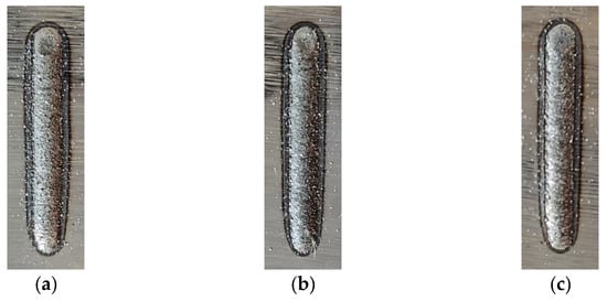
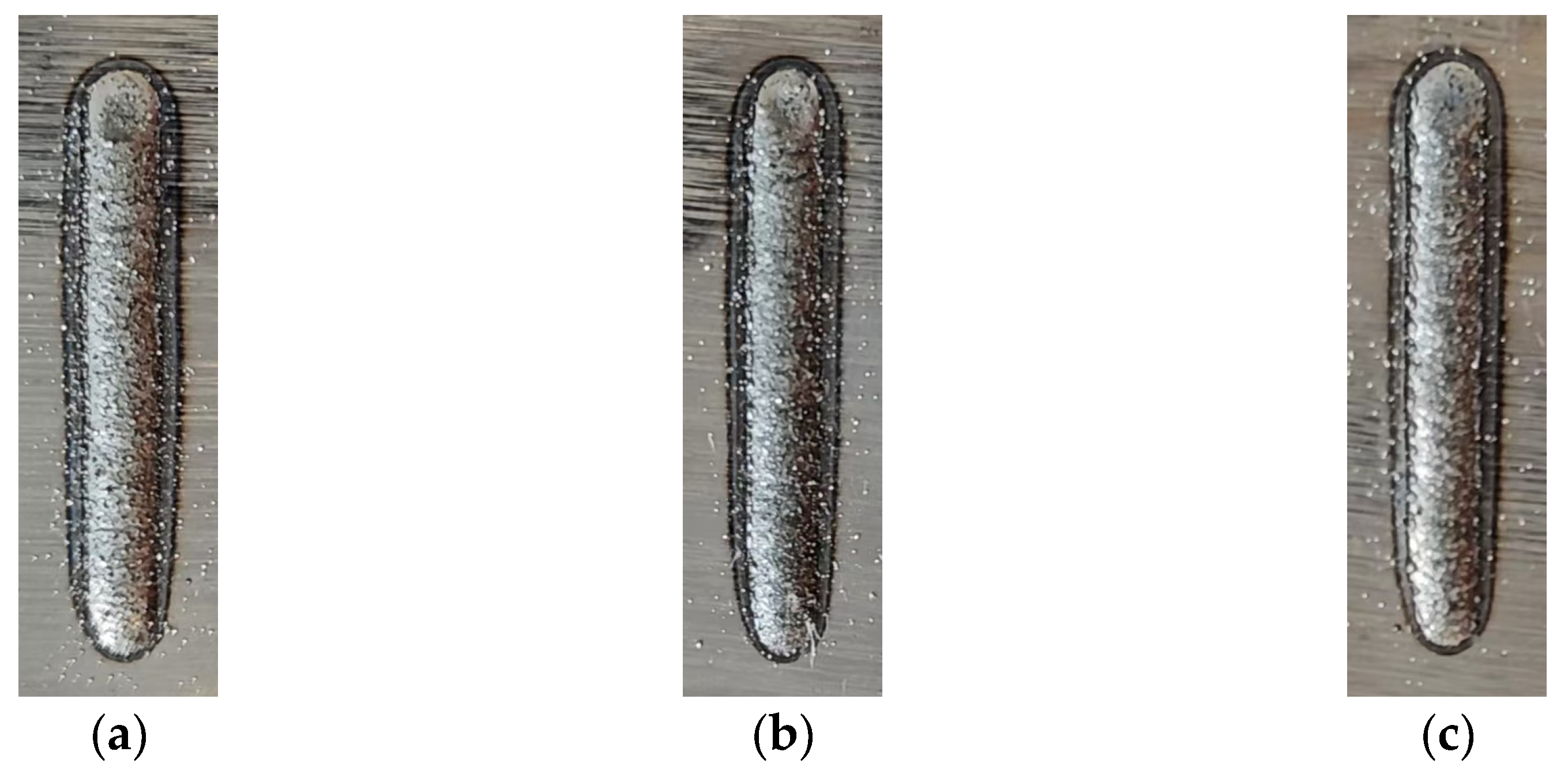
Fe60 alloy powder was doped with CeO2 powder at three mass fractions (1%, 2%, and 3%), respectively. Single-pass laser cladding was performed on the surface of high manganese steel (ZGMn13) under the following parameters: laser power of 1000 W, scanning speed of 10 mm/s, spot radius of 1.5 mm, and single-pass cladding length of 20 mm. The powder feeding rate is 7 g/min, and the defocus distance is 12 mm The macroscopic morphologies of the cladding layers with 1%, 2%, and 3% CeO2 contents are shown in Figure 2. It is observed that the surface of the laser cladding layer is flat, presents a metallic lustre, and the cladding layer exhibits excellent wettability with the substrate. The branch-like striped textures observed on the surface of Figure 2 are surface metal flow ripples formed during molten pool solidification, rather than cracks, dislocations or other microstructural defects. Under high-speed laser irradiation, violent convection occurs inside the molten metal pool; flow traces of liquid metal are preserved on the coating surface after rapid solidification and form these striped morphologies.
Figure 2.
Macroscopic morphologies of laser cladding layers with different mass fractions of CeO2 rare-earth powder additions. (a) 1% CeO2 rare-earth powder addition. (b) 2% CeO2 rare-earth powder addition. (c) 3% CeO2 rare-earth powder addition.
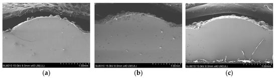
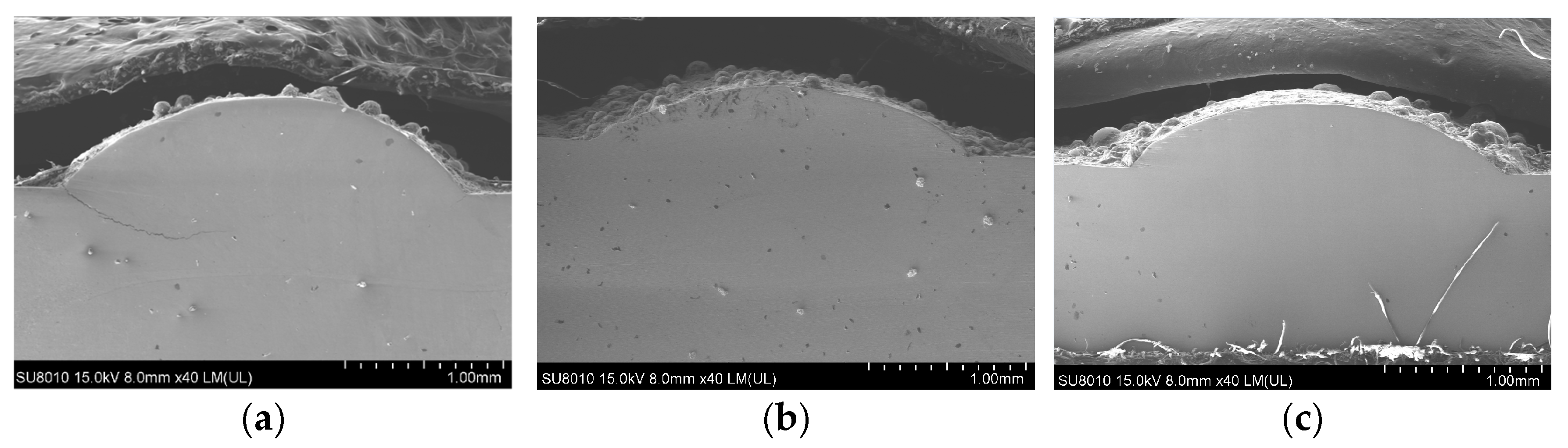
Figure 3 shows the microscopic morphology of the cross-sections of single-pass composite coating layers with different mass fractions of CeO2 rare-earth powder. When 1% CeO2 powder is added, cracks are still observed in the cross-sectional morphology of the laser cladding layer. In contrast, no cracks are generated in the cladding layers with 2% and 3% CeO2 additions. The underlying mechanisms are analyzed as follows: CeO2 acts as a heterogeneous nucleation promoter, refining the grain structure of the cladding layer. When the addition amount is insufficient (1%), the content of rare-earth elements is too low to effectively modify the entire cladding layer, resulting in the persistence of cracks [13,14]. On the one hand, an adequate addition of CeO2 increases the number of nucleation sites, facilitates the formation of fine grains, improves the toughness of the cladding layer, and reduces the cracking tendency. On the other hand, CeO2 addition further enhances the wettability of the molten pool, promotes molten pool fluidity, improves the metallurgical bonding strength between the cladding layer and the substrate, reduces internal defects, and thereby inhibits crack initiation and propagation. Therefore, subsequent multi-pass laser cladding tests in this study will focus on composite alloy powders with 2% and 3% CeO2 additions, with systematic analysis of their organization and properties.
Figure 3.
Microscopic morphology of the cross-section of laser cladding layers with different mass fractions of CeO2 rare-earth powders additions, captured by SU8010 SEM under 10–15 kV operating voltage. (a) 1% CeO2 rare-earth powder addition. (b) 2% CeO2 rare-earth powder addition. (c) 3% CeO2 rare-earth powder addition.
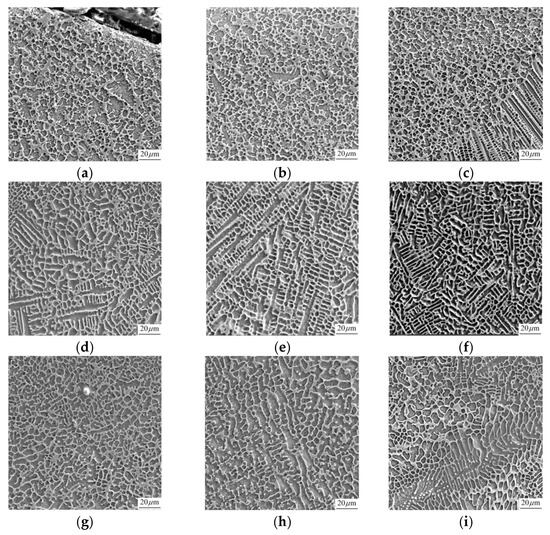
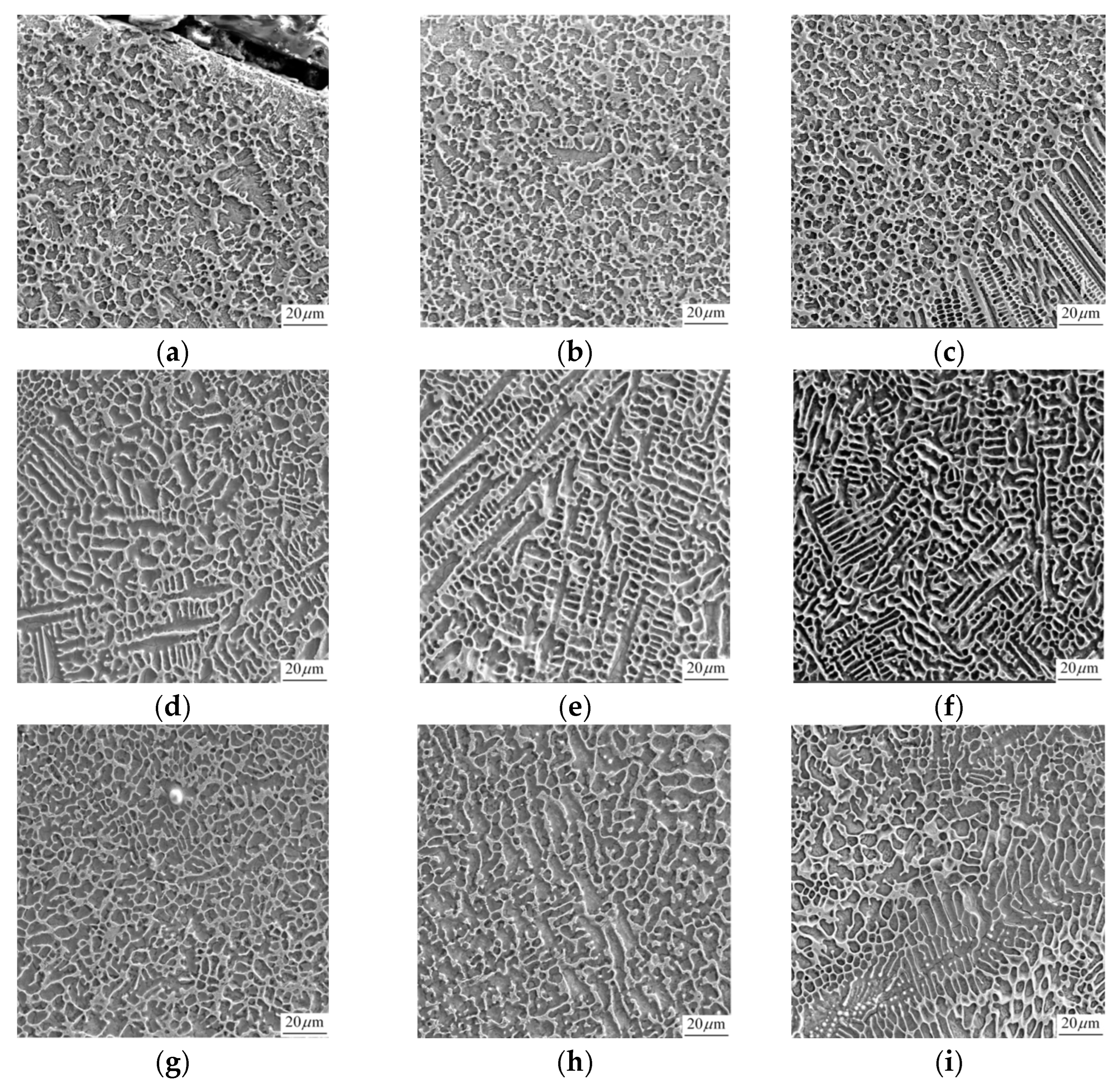
As shown in Figure 4, the SEM histomorphology of the top, middle, and bottom regions of the fused cladding layers with different mass fractions of CeO2 rare-earth powder are presented. For the laser cladding layer prepared without CeO2 addition (Figure 4a–c), it is observed that the top and middle regions are dominated by coarse equiaxed grains, with a small number of dendrites dispersed therein. In contrast, when 2% CeO2 rare-earth powder is added, the microstructure of the laser cladding layer becomes dense and uniformly distributed, with significantly refined grain sizes. Specifically, the top region is transformed from a predominantly equiaxed grain structure to a mixed structure consisting of directional dendrites as the main component and a small number of equiaxed grains. The middle region is composed entirely of dendrites, while the bottom region is characterized by columnar grains.
Figure 4.
Microstructures and morphologies of different regions of fusion cladding layer with different contents of CeO2 rare-earth powders. (a) Top of the 0% CeO2 cladding layer. (b) Middle of the 0% CeO2 cladding layer. (c) Bottom of the 0% CeO2 cladding layer. (d) Top of the 2% CeO2 cladding layer. (e) Middle of the 2% CeO2 cladding layer. (f) Bottom of the 2% CeO2 cladding layer. (g) Top of the 3% CeO2 cladding layer. (h) Middle of the 3% CeO2 cladding layer. (i) Bottom of the 3% CeO2 cladding layer.
After adding 3% CeO2 rare-earth powder, the solidified microstructure of the laser cladding layer is similar to that of the cladding layer formed with 2% CeO2 addition, but the grains in the top region of the cladding layer exhibit a reticulated structure. Meanwhile, the grains in the middle and bottom regions become slightly coarsened. It can be concluded that doping an appropriate amount of CeO2 rare-earth powder in the fused cladding powder can achieve a grain refinement effect, whereas excessive addition of CeO2 will induce grain coarsening [15,16]. The mechanisms underlying the above phenomena are elaborated as follows: in the absence of CeO2 addition, the molten pool lacks high-melting-point heterogeneous nucleation sites. The limited number of nuclei tends to grow freely in all directions during the solidification process, thereby forming coarse equiaxed grains. Meanwhile, affected by the thermal accumulation effect of multi-pass cladding, the preceding cladding pass exerts a preheating effect on the subsequent pass in terms of heat input. This alters the temperature gradient of the molten pool, reduces both the temperature gradient and cooling rate in the central region of the molten pool, and thus increases the grain shape factor, leading to grain coarsening.
A lower cooling rate reduces the G/R ratio, leading to the formation of course equiaxed crystals. In contrast, the addition of high-melting-point CeO2 powder introduces numerous nanoscale particles into the melt, which serve as effective sites for heterogeneous nucleation and thus markedly increase the nucleation density [16]. The high-density nuclei lead to intense competition between grains, with the preferred dendrite crystals inhibiting each other’s lateral growth in a limited space; the spacing between the main trunks decreases, resulting in the densification of the dendrite main trunks. In addition, during the solidification process, Ce elements become enriched in the dendrites, leading to the solute drag effect. This effect significantly reduces the lateral growth rate of the dendrites, causing the grains to grow preferentially along the direction of heat flow. At the same time, the Ce elements enriched in the grain boundaries play a pinning role, inhibiting the growth of dendritic crystals. All these reasons will result in the fusion cladding layer having numerous obvious directional features and exhibiting fine, dense dendrites. With the increase in CeO2 powder content, excess CeO2 will cause the fusion cladding layer to requiring higher energy for melting and diffusion, which in turn triggers the agglomeration of rare-earth elements. This slows down the flow of liquid in the molten pool and the diffusion of the elements, reduces the nucleation efficiency, and increases grain size. Therefore, the addition of CeO2 should be balanced between grain refinement and agglomeration avoidance, so that the performance of the cladding layer can reach the best state. Defect control evidence: Appropriate CeO2 effectively eliminates microcrack defects in low-doping coatings and reduces internal pores, matching the molten pool purification mechanism of rare-earth oxides. The solidified structure distribution of the cladding layer after the addition of rare-earth powder is inconsistent with the phenomenon described by the traditional solidification theory, indicating that the main reason for the increase in dendrites in the cladding layer at this time is the increase in the heterogeneous nucleation core and the solute drag effect, rather than the change in temperature gradient, which is a secondary factor in the formation of the solidified structure [17].
4.2. Microhardness Analysis of Laser Cladding
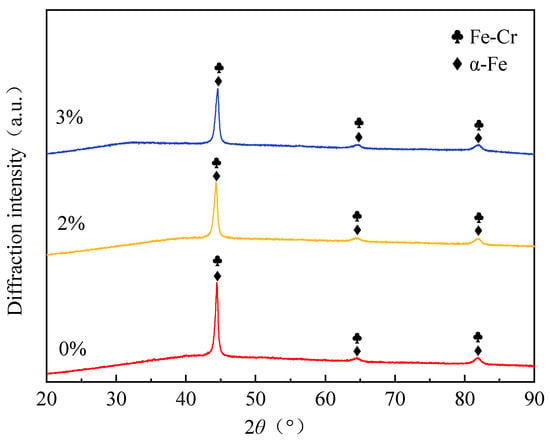
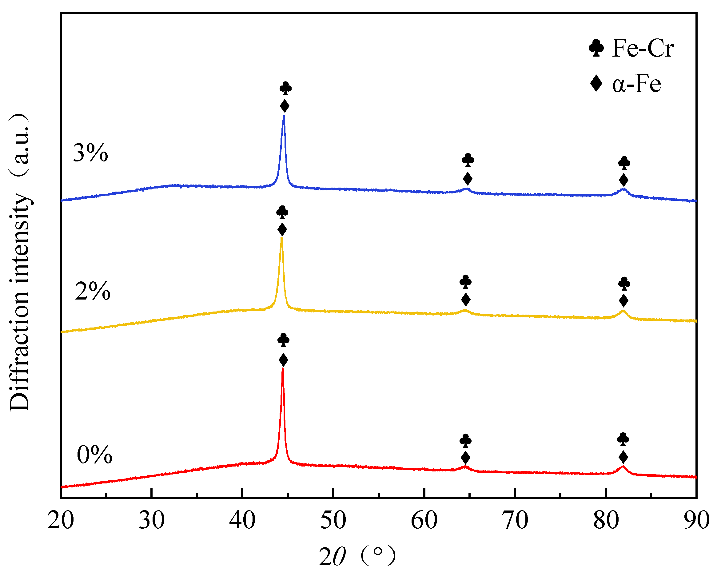
The XRD technique was used to identify the phase composition of the composite cladding layers with different contents of CeO2 rare-earth powder. The experimental data were analyzed using Jade software. The results, as shown in Figure 5, indicate that the phase composition of the composite cladding layers is primarily composed of Fe-Cr intermetallic compounds and an α-Fe solid solution phase. By analyzing the phase composition of the fusion cladding layers with different CeO2 doping levels, no CeO2 phase was detected, which is attributed to the small amount of CeO2 powder added [18]. Moreover, the addition of 2% and 3% CeO2 rare-earth powders did not significantly change the primary phase structure, which remained dominated by Fe-Cr intermetallic compounds and α-Fe solid solutions. Among them, the Fe-Cr intermetallic compounds have a crystal structure with high intrinsic hardness, and these compounds strengthen the cladding layer by means of dispersion, pinning, and hindering dislocation motion.
Figure 5.
XRD patterns of fusion cladding layers with different contents of CeO2 rare-earth powders.
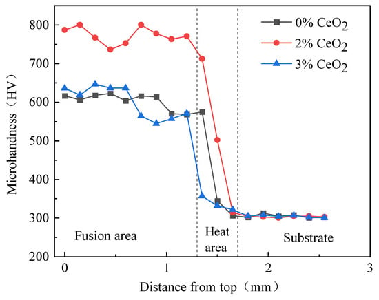
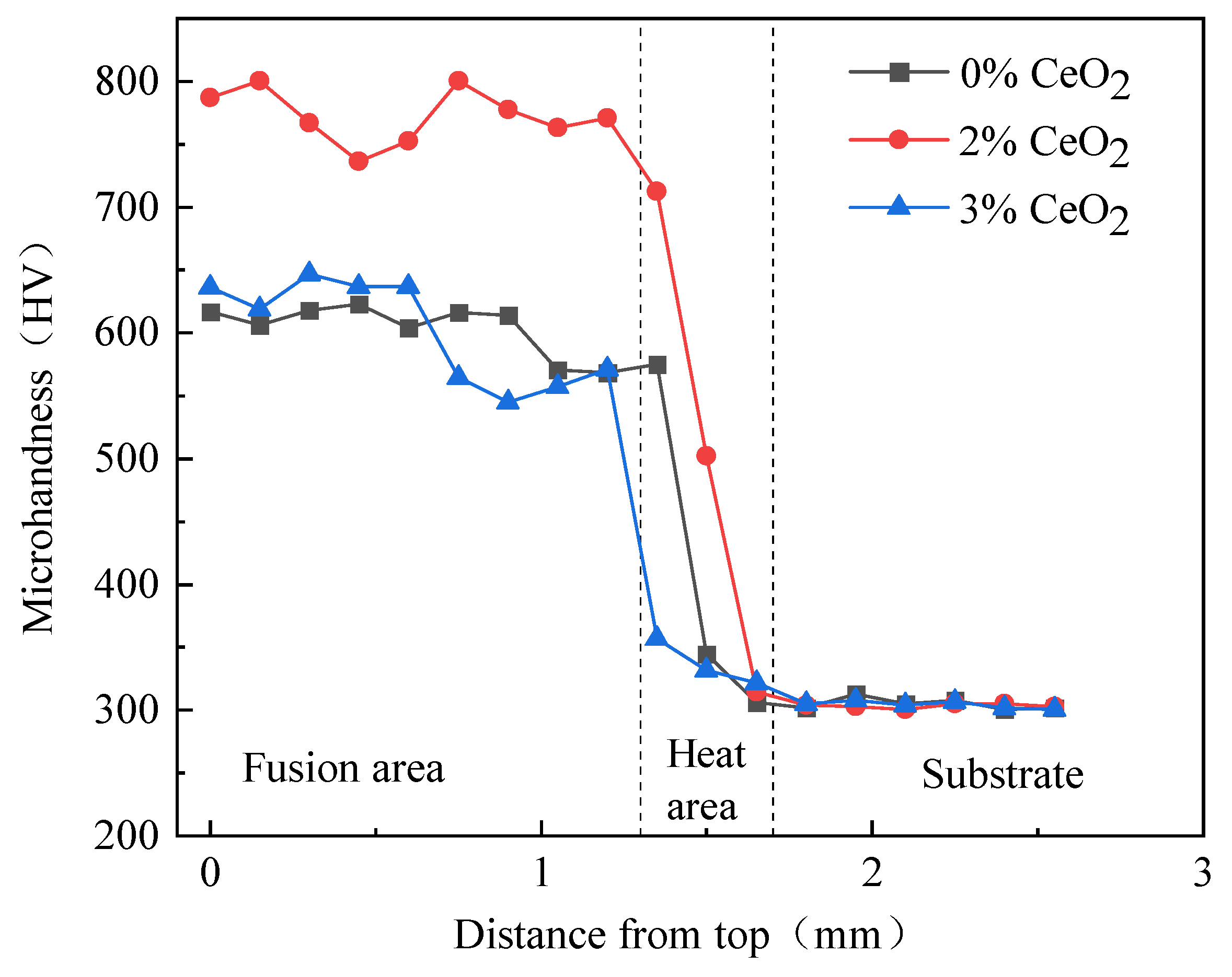
Figure 6 shows the microhardness distribution of fusion cladding layers with different contents of CeO2. The cross-sectional microhardness of these cladding layers exhibits three characteristic gradient change regions. Along the direction from the top of the fusion cladding layer to the substrate, the fusion cladding reinforcement zone, heat-affected transition zone, and substrate zone are formed sequentially. The microhardness data indicates a gradient-decreasing trend across these three regions, with no obvious hardness mutation between adjacent regions. This continuous gradient hardness distribution confirms the formation of a metallurgical bonding interface between the cladding layer and the substrate, which enables smooth transition of the stress field, significantly reduces the failure risk of the cladding layer, and thus extends the service life of high manganese steel jaws.
Figure 6.
Distribution of microhardness of fused cladding layer with different content of CeO2 rare-earth powder.
As can be seen from the figure, the microhardness of the fused cladding layers with three different CeO2 contents is higher than that of the matrix. Combined with the phase analysis results, the reason why the microhardness of the fused cladding layer is higher than that of the matrix is as follows: Fe-Cr intermetallic compounds with high intrinsic hardness exist in the fused cladding layers with three different CeO2 contents, which improve the microhardness of the fused cladding layer by pinning dislocations and hindering their movement. The average microhardness of the fused cladding layer without CeO2 powder added was 594.95 HV; the average microhardness of the fused cladding layer with 2% CeO2 powder added was 772.9 HV; and the average microhardness of the fused cladding layer with 3% CeO2 powder added was 600.5 HV, which are 1.95, 2.53, and 1.96 times higher than that of the matrix, respectively.
The non-monotonic variation in microhardness with CeO2 mass fraction originates from the dual competing effects of CeO2-induced grain refinement and excessive rare-earth agglomeration. For the sample doped with 1% CeO2, the doping dosage is too low to supply sufficient heterogeneous nucleation sites, resulting in a weak grain refinement effect. Residual microcrack defects cannot be eliminated, which deteriorates the overall mechanical properties of the coating. When the CeO2 mass fraction reaches 2%, moderate CeO2 particles are homogeneously dispersed throughout the molten pool and provide abundant nucleation sites. Coupled with the solute drag effect and grain boundary pinning effect, uniform, dense and fine dendritic structures free of microcracks are formed inside the coating, delivering the optimal microhardness performance. In contrast, the sample with 3% CeO2 suffers from severe agglomeration of rare-earth particles in the molten pool. These agglomerated CeO2 clusters raise the energy barrier for melting and element diffusion, lower the nucleation efficiency, and trigger partial coarsening of dendrites as well as aggravated microstructural inhomogeneity. Consequently, the microhardness of the 3% CeO2 coating drops markedly compared with that of the 2% counterpart.
Combined with the analysis results of the fused cladding layer, it can be seen that the fused cladding layer with 2% CeO2 powder added has the finest and densest grain structure due to the heterogeneous nucleation and solute drag effects, leading to increased microhardness. In contrast, the fused cladding layer with 3% CeO2 powder added has excessive powder content, resulting in agglomeration of rare-earth elements, reduced nucleation rate of the molten pool, grain coarsening, and decreased microhardness [16].
4.3. Wear Resistance Test Results of Laser Cladding Layers
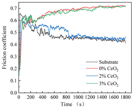
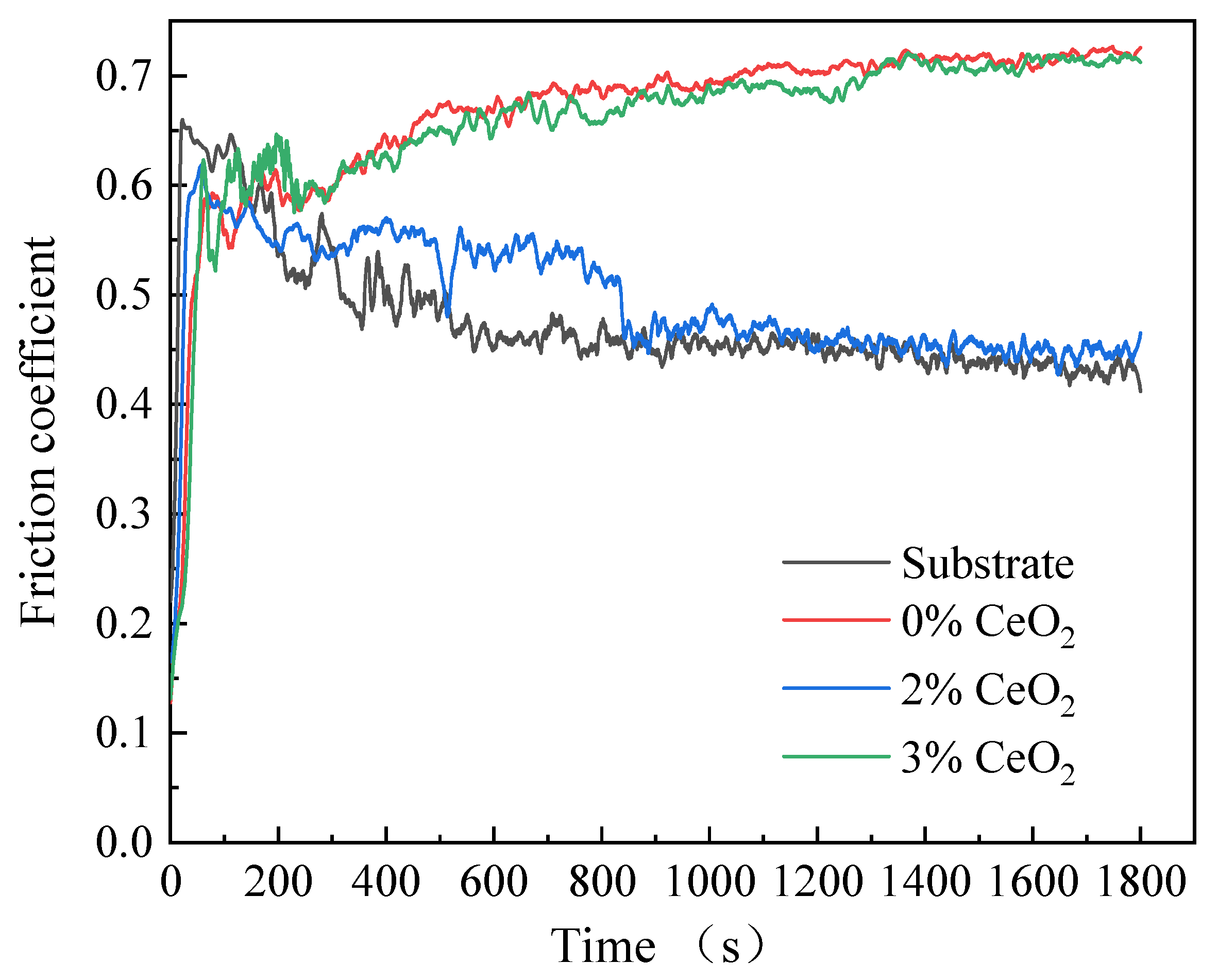
There is a positive correlation between the coefficient of friction and wear loss. Generally, the smaller the coefficient of friction, the better the wear resistance. However, this relationship is not linear and is influenced by various factors. As depicted in Figure 7, the friction coefficient curves of the fusion cladding layers with different contents of CeO2 rare-earth powder and the substrate are shown. All four curves enter the stable wear stage after 900 s, with the friction coefficient curves exhibiting small fluctuations. Among them, the friction coefficients of the matrix and the fused cladding layer with 2% CeO2 rare-earth powder are similar, and their average friction coefficients are 0.441 and 0.452, respectively.
Figure 7.
Friction coefficient curves of fusion cladding layers and substrate with different contents of CeO2 rare-earth powders.
In comparison, the average friction coefficients of the fused cladding layer with no added CeO2 powder (0.711) and with 3% CeO2 powder added (0.696) are obviously larger than that of the optimal 2% CeO2 fused cladding layer. With the increase in CeO2 content, the friction coefficient exhibits a trend of decreasing first and then increasing. This trend corresponds to the microstructural evolution of the cladding layer, where the grains first refine and then coarsen with increasing CeO2 content [19]. The relatively low friction coefficient of the substrate is attributed to the absence of hard particles, leading to a wear mechanism dominated by adhesion [20]. In this mechanism, the surface asperities are progressively smoothed, resulting in a lower friction coefficient.
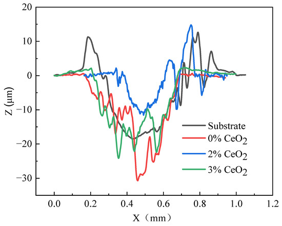
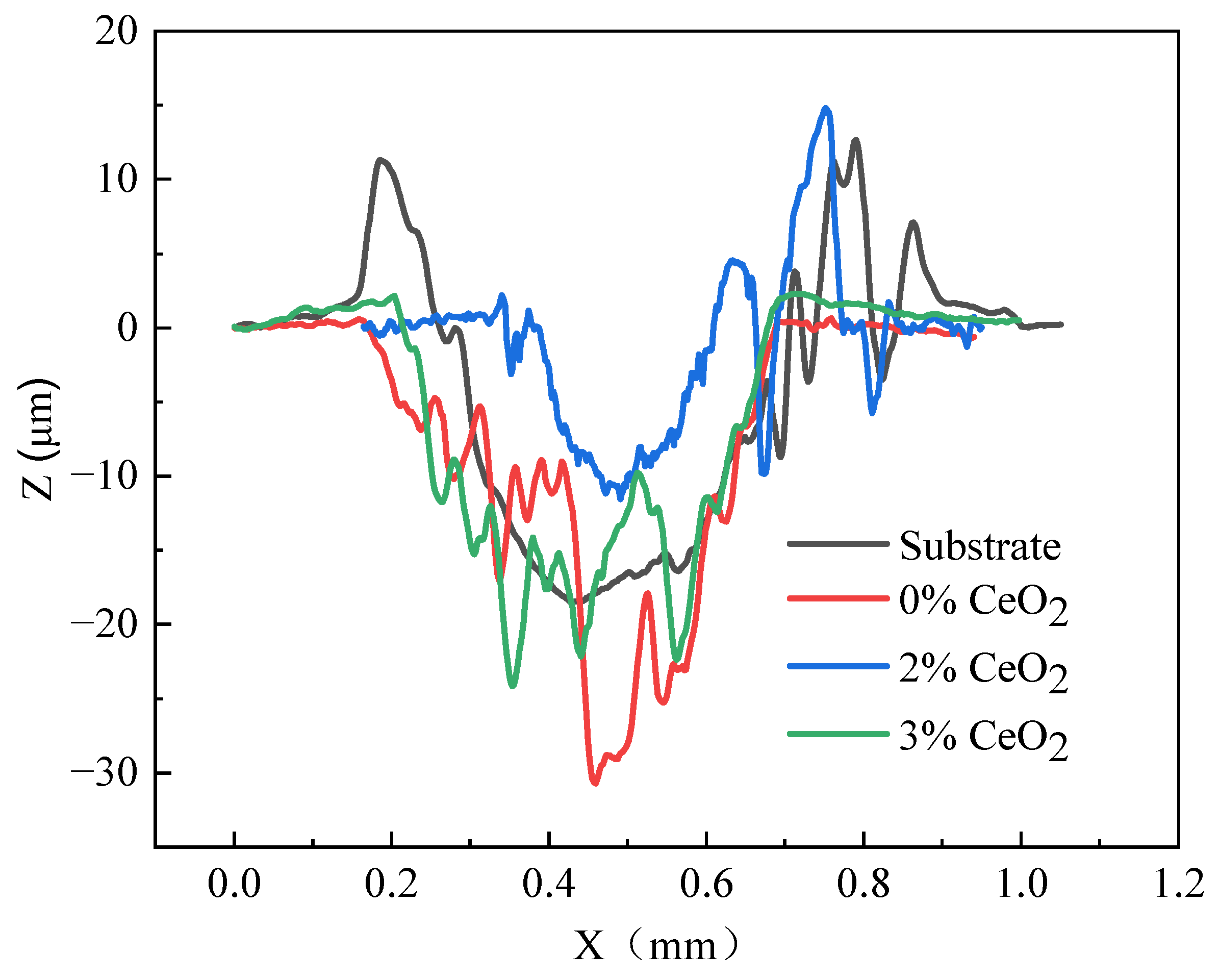
Figure 8 shows the wear cross-section profiles of the fusion cladding layers with different contents of CeO2 rare-earth powder and the substrate. From the figure, it is evident that the fusion cladding layer with 2% CeO2 rare-earth powder added has the smallest cross-sectional wear area. Its cross-sectional wear profile is relatively smooth, although it exhibits both abrasive wear and adhesive wear characteristics. The substrate’s cross-sectional profile curve is the smoothest, with no parallel grooves or plough marks, which explains why the substrate’s friction surface tends to become smooth, has a low friction coefficient, and is dominated by adhesive wear [21]. The cross-sectional profile curves of the fusion cladding layer without CeO2 powder and with 3% CeO2 powder added show obvious grooves and plough marks, which are dominated by abrasive wear, resulting in a large wear area and poor wear resistance.
Figure 8.
Cross-sectional contours of abrasion marks on fusion cladding layers and substrate with different contents of CeO2 rare-earth powders.
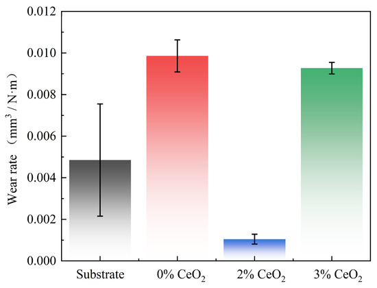
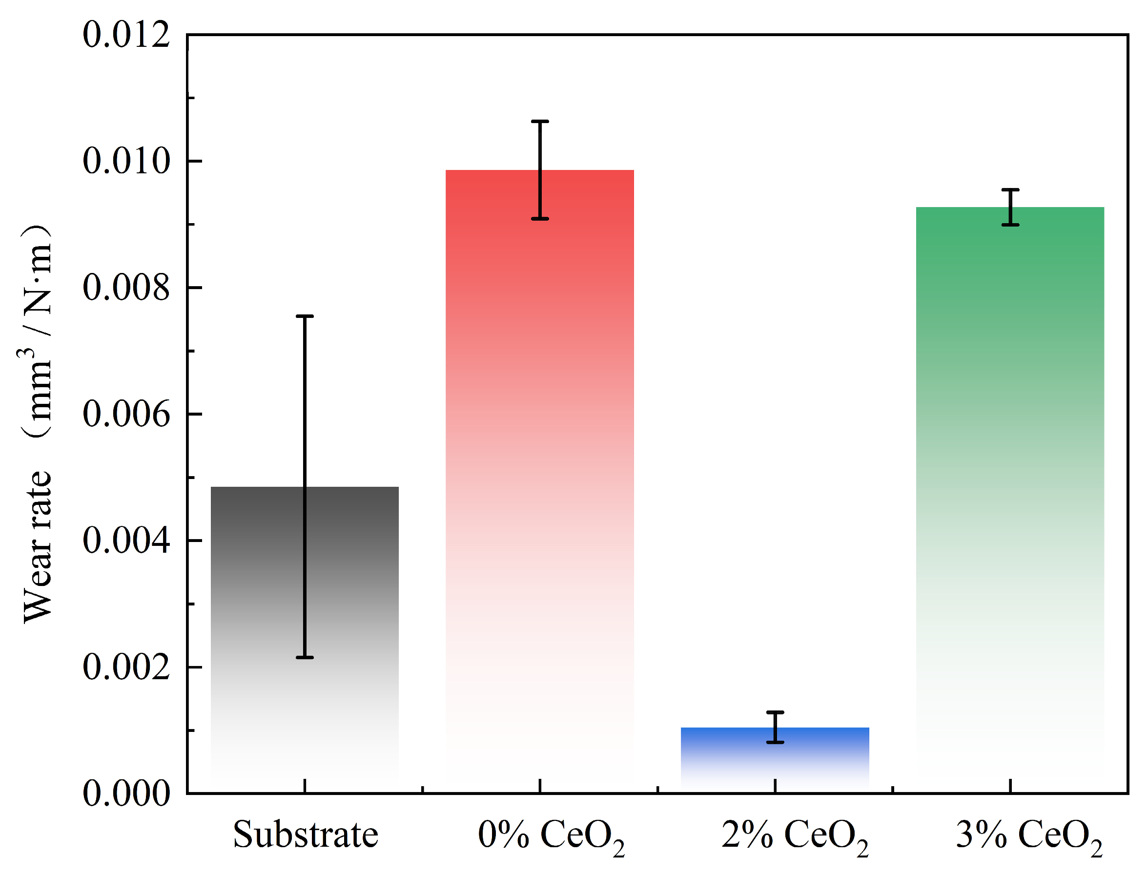
Figure 9 shows the wear rates of the fused cladding layers with different contents of CeO2 powder and the substrate. As can be seen, the wear rates of the fused cladding layer without CeO2 powder and with 3% CeO2 powder are large, at 0.0314 mm3/(N∙m) and 0.0295 mm3/(N∙m), respectively, exceeding the substrate’s wear rate of 0.0154 mm3/(N∙m). The wear rate of the fused cladding layer with 2% CeO2 powder is the smallest (0.0033 mm3/(N∙m)), which is 78.6% lower than that of the substrate. Combined with Figure 4, the results suggest that the inferior wear resistance of the CeO2-free cladding layer is associated with coarse, low-density equiaxed grains formed under reduced temperature gradients and cooling rates. The fused cladding layer with 2% CeO2 powder added undergoes heterogeneous nucleation, solute drag effect, the pinning effect, and enhanced molten pool mobility, resulting in the formation of fine and dense dendrites and improved wear resistance. The addition of 3% CeO2 powder to the fused cladding layer initially improves wear resistance, but excessive CeO2 causes agglomeration of rare-earth elements, leading to re-coarsening of dendrites and thus reduced wear resistance of the cladding layer. It is worth noting that the wear rate of the substrate is lower than that of the fused cladding layer without CeO2 powder and 3% CeO2 powder. It is hypothesized that during the friction and wear experiments, the friction pair rubbed against the surface of the high manganese steel at high speeds, causing work hardening on the surface of the high manganese steel, which enhanced the wear resistance of the substrate surface. It can be concluded that fusing Fe60 alloy powder with 2% CeO2 rare-earth powder on the surface of high manganese steel can significantly improve the wear resistance of the high manganese steel surface.
Figure 9.
Wear rates of fused cladding layers and substrates with different contents of CeO2 rare-earth powder added.
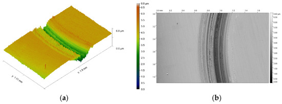
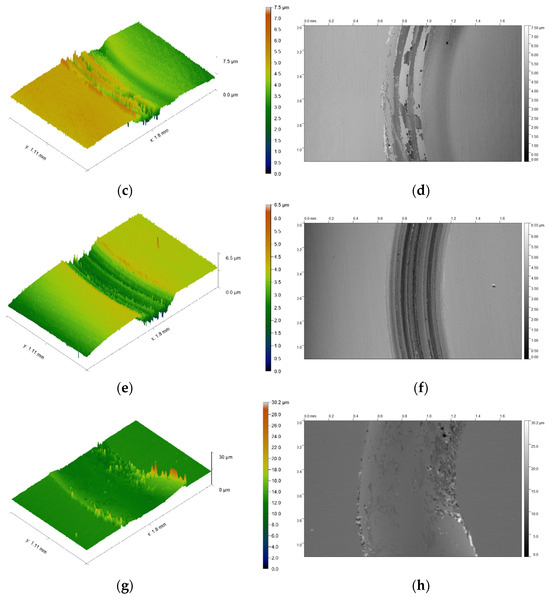
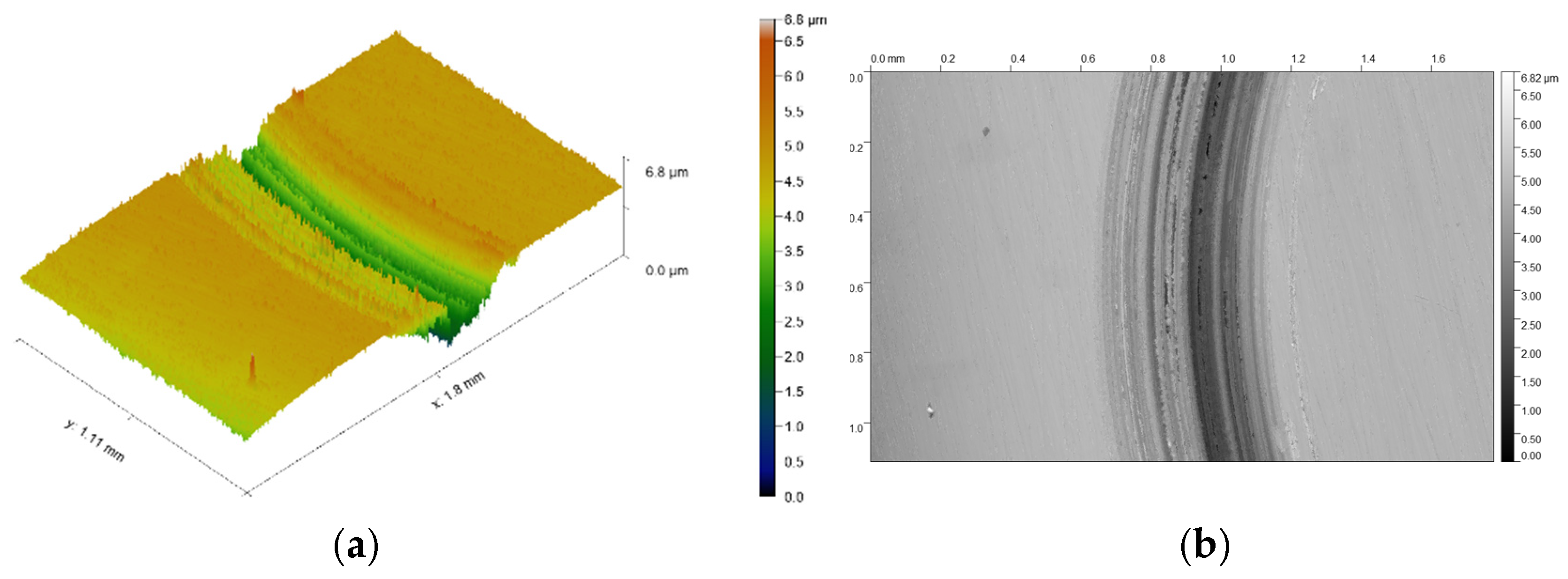
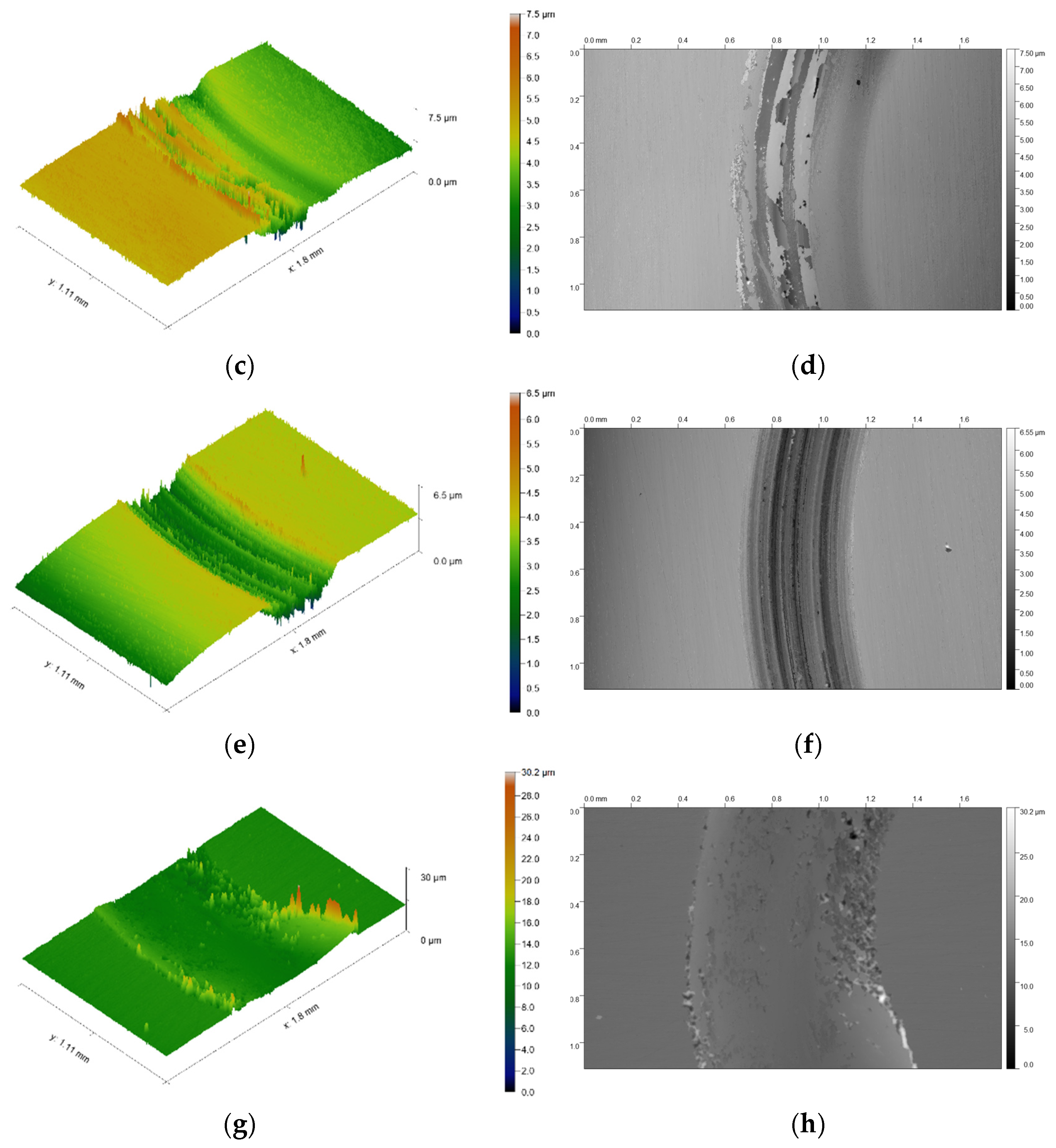
Figure 10 illustrates the three-dimensional topography scanning maps and abrasion topographies of the fused cladding layers with varying CeO2 rare-earth powder contents and the substrate surface. As shown, the surface of the fused cladding layer without CeO2 powder exhibits no obvious grooves or plough marks, indicating that abrasive wear is the dominant mechanism. A small number of grooves and adhesive shedding appeared on the surface of the fused cladding layer with 2% CeO2 powder added, and its wear type is a combination of abrasive and adhesive wear. The substrate shows indistinct parallel grooves or plough marks, with wear marks dominated by adhesive wear. It can also be seen that the trend of their wear characteristics is consistent with the previous results. These observations indicate that the addition of 2% CeO2 promotes a transition from purely abrasive wear to a mixed abrasive–adhesive wear mode, whereas the substrate is dominated by adhesive wear. The consistency with previous results further confirms the distinct influence of CeO2 content on the wear mechanisms of the cladding layers.
Figure 10.
Scanning images of 3D morphology and abrasion marks on the surface of fused cladding layers and substrate with different contents of CeO2 rare-earth powders. (a) Scan of the 3D morphology of the abrasion marks of the 0% CeO2-added cladding layer. (b) Abrasion mark with 0% CeO2 coating. (c) Scan of the 3D morphology of the abrasion marks of the 2% CeO2-added cladding layer. (d) Abrasion mark with 2% CeO2 coating. (e) Scan of the 3D morphology of the abrasion marks of the 3% CeO2-added cladding layer. (f) Abrasion mark with 3% CeO2 coating. (g) Scan of the 3D morphology of the abrasion marks of substrate abrasions. (h) Abrasion mark with substrate abrasions.
5. Conclusions
The effect of CeO2 rare-earth powder addition on the overall performance of laser-clad Fe60 alloy cladding layers on ZGMn13 high manganese steel jaw plates was systematically investigated in this work. Different from conventional rigid ceramic reinforcing particles such as Al2O3 and SiC which easily induce interfacial stress concentration and microcrack initiation under impact load, this study adopts low-concentration CeO2 ranging from 1 to 3 wt% to realize surface strengthening of Hadfield high manganese steel and effectively overcome the intrinsic cracking defect of ceramic-reinforced cladding coatings. The results demonstrated that single-pass laser cladding of Fe60 alloy powders with 1%, 2%, and 3% CeO2 powders revealed obvious microcracks in the 1% CeO2 cladding layer, whereas no cracks were produced in the 2% and 3% CeO2 cladding layers, indicating that the addition of an appropriate amount of CeO2 rare-earth powders can effectively inhibit cladding layer cracking. The average microhardness values for the layers without CeO2, with 2% CeO2, and with 3% CeO2 were 594.95 HV, 772.9 HV, and 600.5 HV, respectively, representing 1.95, 2.53, and 1.96 times the hardness of the substrate. The fused cladding layer with 2% CeO2 powder exhibits the highest microhardness, attributed to the heterogeneous nucleation and solute drag effects, which result in the finest and densest grains. Friction and wear experiments on the fused cladding layers with different CeO2 contents and the substrate revealed that the fused cladding layer with 2% CeO2 powder has the best wear resistance, with a wear rate of 0.0033 mm3/(N∙m), 78.6% lower than that of the substrate. In comparison, the wear resistance of the fused cladding layer with 3% CeO2 powder deteriorates, with a wear rate of 0.0295 mm3/(N∙m). During the friction and wear process, the surface wear of the fused cladding layers without CeO2 powder and with 3% CeO2 powder is dominated by abrasive wear, while the surface of the fused cladding layer with 2% CeO2 powder exhibits a combination of abrasive and adhesive wear. This research clarifies the optimal CeO2 doping concentration and its internal modification mechanism and provides reliable component selection reference and complete laser cladding process guidance for the surface strengthening of ZGMn13 high manganese steel jaw plate components in jaw crushers, possessing important engineering application value for prolonging the service life of heavy-duty crushing equipment parts.
Author Contributions
Conceptualization, X.C.; methodology, Z.Z.; software, R.J.; validation, R.J.; formal analysis, Z.Z. and R.J.; investigation, Z.Z. and R.J.; resources, X.C. and C.T.; data curation, Z.Z.; writing—original draft preparation, Z.Z.; writing—review and editing, C.T.; visualization, R.J.; supervision, C.T.; project administration, C.T.; funding acquisition, X.C. All authors have read and agreed to the published version of the manuscript.
Funding
This research received no external funding.
Institutional Review Board Statement
Not applicable.
Informed Consent Statement
Not applicable.
Data Availability Statement
Data are contained within the article.
Conflicts of Interest
The authors declare no conflicts of interest.
References
- Slobodianskii, M. Lifetime Prediction for the Jaw Crusher by the Criterion of Toggle Fatigue Strength Based on the Application of the Kinetic Concept of Material Destruction; Springer International Publishing: Cham, Switzerland, 2022. [Google Scholar]
- Guo, C.; Zhou, J.; Chen, J.; Zhao, J.; Yu, Y.; Zhou, H. High temperature wear resistance of laser cladding NiCrBSi and NiCrBSi/WC-Ni composite coatings. Wear 2011, 270, 492–498. [Google Scholar]
- Zhu, L.; Xue, P.; Lan, Q.; Meng, G.; Ren, Y.; Yang, Z.; Xu, P.; Liu, Z. Recent research and development status of laser cladding: A review. Opt. Laser Technol. 2021, 138, 106915. [Google Scholar] [CrossRef] [Scilit]
- Sun, J.; Zhao, Y.; Yang, L.; Zhao, X.; Qu, W.; Yu, T. Effect of shielding gas flow rate on cladding quality of direct laser fabrication AISI 316L stainless steel. J. Manuf. Process. 2019, 48, 51–65. [Google Scholar] [CrossRef] [Scilit]
- Shi, Q.; Zhu, H.; Li, C. The Effects of the Addition of Ti3SiC2 on the Microstructure and Properties of Laser Cladding Composite Coatings. Coatings 2020, 10, 498. [Google Scholar] [CrossRef] [Scilit]
- Kathuria, Y.P. Modulation and scanning-frequency effects in laser cladding process. In Proceedings of the SPIE Lasers and Optics in Manufacturing; SPIE: Bellingham, WA, USA, 1997. [Google Scholar]
- Wirth, F.; Wegener, K. Simulation of the multi-component process gas flow for the explanation of oxidation during laser cladding. Addit. Manuf. 2018, 24, 249–256. [Google Scholar] [CrossRef] [Scilit]
- Riquelme, A.; Rodrigo, P.; Dolores Escalera-Rodríguez, M.; Rams, J. Analysis and optimization of process parameters in Al-SiCp laser cladding. Opt. Lasers Eng. 2016, 78, 165–173. [Google Scholar] [CrossRef] [Scilit]
- Murugesan, A.; Biswas, K. Microstructural evolution and phase analysis of SS410–Al2O3-SiC multilayered functionally graded composite fabricated through laser cladding. Ceram. Int. 2024, 50, 34901–34913. [Google Scholar] [CrossRef] [Scilit]
- Moussaoui, K.; Segonds, S.; Rubio, W.; Mousseigne, M. Studying the measurement by X-ray diffraction of residual stresses in Ti6Al4V titanium alloy. Mater. Sci. Eng. A 2016, 667, 340–348. [Google Scholar] [CrossRef] [Scilit]
- Wang, K.; Liu, W.; Hong, Y.; Sohan, H.M.S.; Tong, Y.; Hu, Y.; Zhang, M.; Zhang, J.; Xiang, D.; Fu, H.; et al. An Overview of Technological Parameter Optimization in the Case of Laser Cladding. Coatings 2023, 13, 496. [Google Scholar] [CrossRef] [Scilit]
- Yang, C.; Jing, C.; Fu, T.; Lin, T.; Guo, W.; Liu, N. Effect of CeO2 on the microstructure and properties of AlCoCrFeNi2.1 laser cladding coatings. J. Alloys Compd. 2024, 976, 172948. [Google Scholar] [CrossRef] [Scilit]
- Zhang, G.Y.; Wang, C.L.; Gao, Y. Effect of Rare Earth CeO2 Contents on the Tissue Morphology of Laser Cladding on Al Alloy Layers. Surf. Technol. 2015, 44, 1–5. [Google Scholar]
- Pu, J.; Sun, Y.-B.; Wu, L.; He, P.; Long, W.-M. Effect of CeO2 Content on Microstructure and Properties of Ni-Based Tungsten Carbide Layer by Plasma Arc Cladding. Coatings 2022, 12, 342. [Google Scholar] [CrossRef] [Scilit]
- Ye, F.; Shao, W.; Ye, X.; Liu, M.; Xie, Y.; Bian, P.; Wang, X.; Liu, L.; Wu, H. Microstructure and Corrosion Behavior of Laser-Cladding CeO2-Doped Ni-Based Composite Coatings on TC4. J. Chem. 2020, 2020, 8690428. [Google Scholar] [CrossRef] [Scilit]
- Chen, L.; Zhao, Y.; Guan, C.; Yu, T. Effects of CeO2 addition on microstructure and properties of ceramics reinforced Fe-based coatings by laser cladding. Int. J. Adv. Manuf. Technol. 2021, 115, 2581–2593. [Google Scholar] [CrossRef] [Scilit]
- Xiang, D.; Wang, D.; Zheng, T.; Chen, Y. Effects of Rare Earths on Microstructure and Wear Resistance in Metal Additive Manufacturing: A Review. Coatings 2024, 14, 139. [Google Scholar] [CrossRef] [Scilit]
- Li, L.; Sang, S.; Zhu, T.; Li, Y.; Wang, H. Enhancing Hardness and Wear Resistance of MgAl2O4/Fe-Based Laser Cladding Coatings by the Addition of CeO2. Coatings 2024, 14, 550. [Google Scholar] [CrossRef] [Scilit]
- Wu, J.; Zhang, J.; Chen, D.; Huang, J.; Shi, W.; An, F.; Wu, X. Study on the Effect of CeO2 on the Performance of WC + Ni60 Laser Cladding Coating. Lubricants 2025, 13, 24. [Google Scholar] [CrossRef] [Scilit]
- Zhang, C.X.; Sun, W.C.; Liu, E.Y.; Liu, Y.W.; Liu, J.P.; Zhang, B.; Xu, Y.F.; Zhou, M.-R. Effects of CeO2/Y2O3 rare earth oxides on microstructure and properties of in-situ synthesized wc-reinforced ni-based cladding layer. J. Min. Metall. Sect. B-Metall. 2024, 60, 139–152. [Google Scholar] [CrossRef] [Scilit]
- Jia, Z.N.; Yang, Y.Y.; Qi, X.W.; Song, X.M. Influence of nano-serpentine mineral powder as a lubricating additive on the high-temperature tribological properties of metal friction pairs. Bulg. Chem. Commun. 2017, 49, 948–954. [Google Scholar]

Disclaimer/Publisher’s Note: The statements, opinions and data contained in all publications are solely those of the individual author(s) and contributor(s) and not of MDPI and/or the editor(s). MDPI and/or the editor(s) disclaim responsibility for any injury to people or property resulting from any ideas, methods, instructions or products referred to in the content. |
© 2026 by the authors. Licensee MDPI, Basel, Switzerland. This article is an open access article distributed under the terms and conditions of the Creative Commons Attribution (CC BY) license.