


Highlights
- An analytical uniaxial tensile σ-w model for 3D/4D/5D SFRC were proposed.
- Uniaxial tensile σ-w tests for SFRC were systematically conducted.
- Uniaxial tensile properties for multiple hooked-end SFRC were analyzed.
Abstract
Steel-fiber-reinforced concrete (SFRC), as a composite engineering material, exhibits excellent physical and mechanical properties, making it widely applied in civil engineering, construction, water conservancy, transportation, and port industries. To date, significant progress has been made in the research of plain and single-hook (3D) steel-fiber-reinforced concrete both domestically and internationally. With advancements in technology, multi-end hooked 4D and 5D steel fibers have emerged, offering more end hooks and a higher tensile strength. These fibers possess a stronger anchorage capacity with the matrix, and SFRC with multi-end hooked fibers exhibits superior tensile and flexural properties. However, research on multi-end hooked (4D and 5D) steel-fiber-reinforced concrete is still in its early stages, particularly regarding the axial tensile stress–crack width constitutive relationship. The accuracy and rationality of this constitutive relationship directly affect the reliability and precision of structural design. Therefore, in this study, a novel σ-w constitutive relationship model for steel-fiber-reinforced concrete and an axial tensile stress–crack width testing method for SFRC are proposed, based on 16 sets of uniaxial tensile tests. This model considers the comprehensive effects of the concrete matrix, fiber bridging, fiber volume fraction, fiber shape factor (effects of the number of hooked ends), aspect ratio, and crack width.
1. Introduction
Steel-fiber-reinforced concrete (SFRC) is a construction material with a significant crack-arresting capability [1,2,3,4]. The incorporation of steel fibers effectively enhances the mechanical performance of concrete, including the tensile strength, flexural capacity, and energy absorption ability [5,6], leading to its widespread application in various structural and engineering fields. At present, studies on the flexural and tensile behavior of steel fiber (SF)-reinforced concrete mainly focus on the influence of the fiber volume fraction and fiber properties. The existing research indicates that increasing the SF content leads to improvements in fracture toughness, residual strength, and the fracture energy of concrete [7,8,9,10,11].
Fiber geometry also plays an important role in fracture behavior. Compared with straight fibers, hooked-end steel fibers exhibit a superior crack-bridging capacity and provide a higher residual strength and ductility [12,13]. In addition, the fiber aspect ratio has a notable influence on fracture performance [14,15,16]. The inclusion of steel fibers alters the cracking pattern of concrete to a certain extent, and several studies have investigated the crack propagation in fiber-reinforced concrete under flexural tensile stress [17,18].
The post-cracking ductility enhancement in SFRC is largely attributed to the effective bond between steel fibers and the concrete matrix. Consequently, extensive research has been conducted on the bond-slip behavior between fibers and concrete [19,20,21,22,23]. In the design and application of SFRC, understanding the relationship between the uniaxial tensile stress and crack width is of critical importance. This relationship is commonly described by the tensile stress–crack width (σ-w) constitutive relationship, which is a key factor in evaluating the structural performance and safety.
In recent years, both researchers and design codes have emphasized the importance of the σ-w constitutive relationship for SFRC [24,25,26]. During the structural design and assessment, the appropriate selection and application of constitutive models are essential in order to ensure long-term stability and safety. This is particularly true for modern structures subjected to complex loading conditions and involving materials with diverse mechanical properties, where accurate constitutive models can provide more reliable predictions and improved design control.
The σ-w constitutive behavior of SFRC is influenced by multiple factors, including fiber type, fiber volume fraction, fiber aspect ratio, and concrete strength. The interaction among these factors makes the accurate prediction of the σ-w relationship challenging. However, the existing Chinese design specifications, such as the Technical Specification for Steel-Fiber-Reinforced Concrete Structures (CECS 38-1992) [27], Technical Specification for Application of Fiber-Reinforced Concrete (JGJ/T 221-2010) [28], Standard for Test Methods of Fiber-Reinforced Concrete (CECS 13-2009) [29], and Steel-Fiber-Reinforced Concrete (JG/T 472-2015) [30], do not provide experimental methods or constitutive models for the uniaxial tensile σ-w relationship of SFRC. The European Model Code 2010 [31] adopts a simplified linear σ-w relationship for design purposes. In recent studies, Faustmann et al. adopted the direct tensile test combined with the digital image correlation (DIC) technique, which provided detailed insights into the crack width evolution and post-cracking behavior of SFRC [32]. Based on the cohesive zone model (CZM), Sagar et al. proposed a multi-linear tensile stress–crack width relationship to characterize the post-peak softening behavior of SFRC [33].
In practice, however, the tensile response of SFRC varies significantly with the crack width, especially for concrete reinforced with multi-hooked 4D and 5D steel fibers that exhibit an enhanced anchorage capacity. Therefore, the experimental investigation of the uniaxial tensile σ-w relationship of multi-hooked steel-fiber-reinforced concrete is of great significance.
In this chapter, a dog-bone-shaped uniaxial tensile σ-w test method is employed to investigate the effects of fiber hook number, fiber volume fraction, fiber aspect ratio, and concrete strength on the mechanical behavior of notched dog-bone SFRC specimens. Based on the experimental results, the failure modes of SFRC dog-bone specimens are analyzed, and the influences of various parameters on the uniaxial tensile σ-w curves are discussed. In addition, digital image correlation (DIC) technology is utilized to monitor the surface strain field of the specimens, allowing for a detailed analysis of the strain evolution during tensile failure. Based on composite material mechanics theory and regression analysis, a calculation method for the uniaxial tensile strength of SFRC is proposed, and a four-stage uniaxial tensile σ-w constitutive model for SFRC is established.
2. Materials and Experiments
2.1. Materials
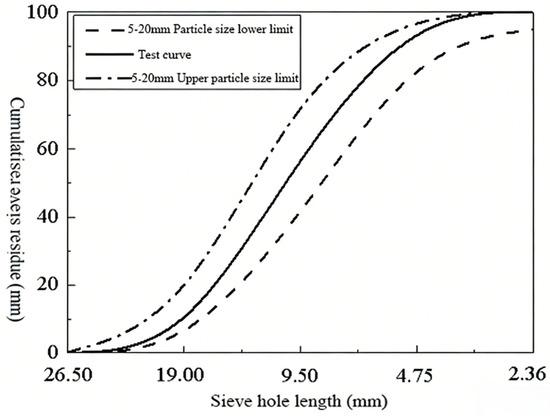
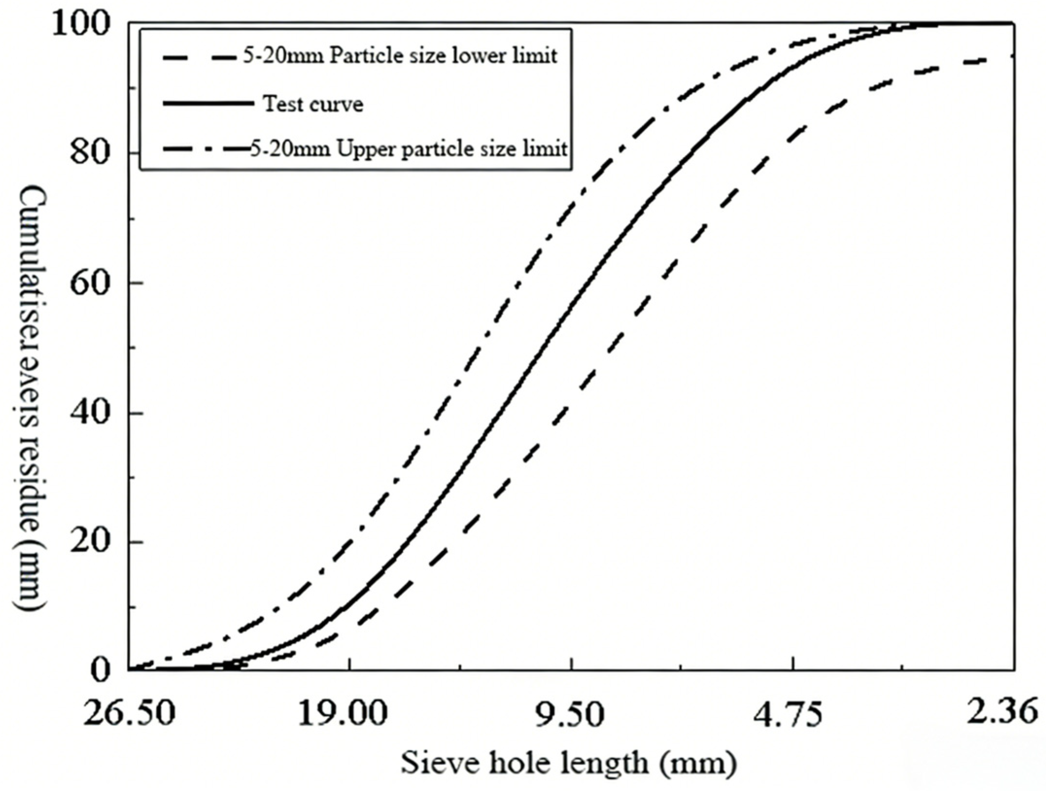
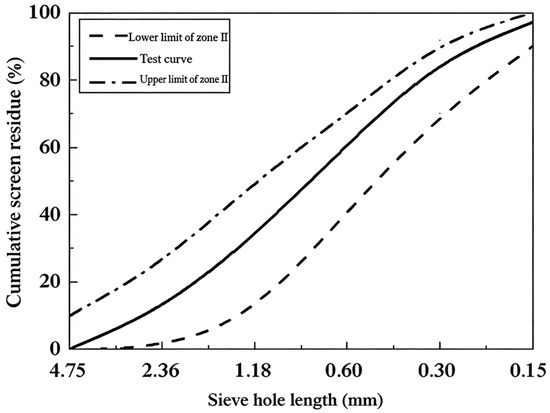
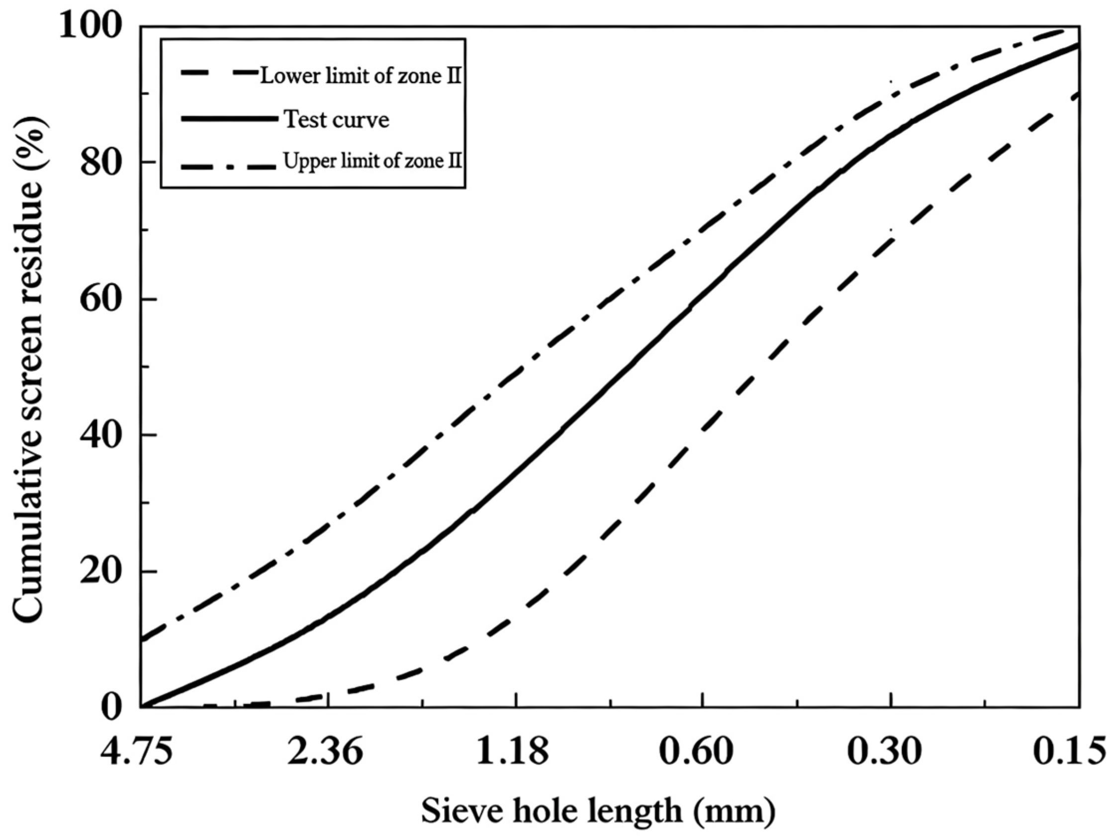
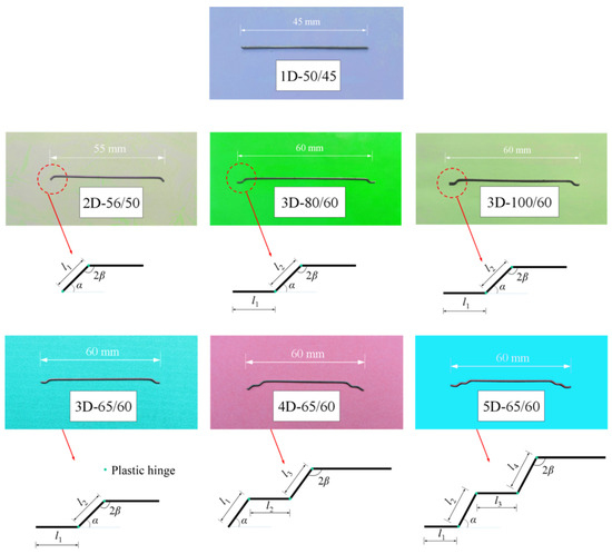
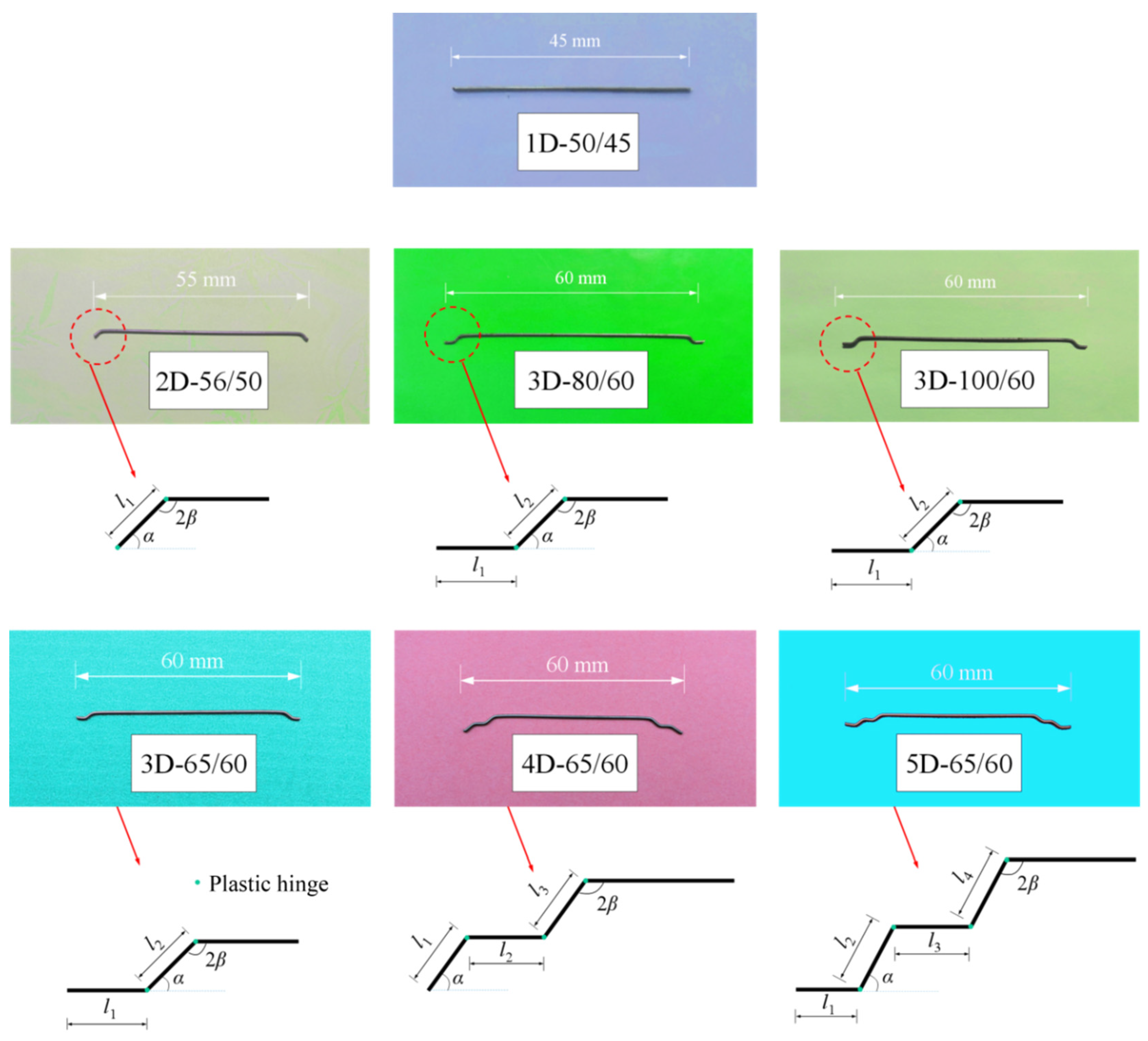
The cement used is P.O 42.5-grade ordinary Portland cement, produced by Tianrui Group Zhengzhou Cement Co., Ltd. (Zhengzhou, China). The performance indicators for the cement are provided in Table 1. Continuously graded limestone gravel with a particle size range of 5–20 mm was used as the coarse aggregate. The grading curve for the coarse aggregate is shown in Figure 1. The fine aggregate used is natural river sand, alongside standard sand from Xiamen Aisiou Standard Sand Co., Ltd. (Xiamen, China) The sand has a particle size range of 0.5–2.0 mm, a fineness modulus of 2.7, good grading, and a density of 2706 kg/m3. The grading curve for the fine aggregate is shown in Figure 2. Tap water was used as the mixing water for the concrete. The superplasticizer for cement mortar is a powder polycarboxylate superplasticizer with a water reduction efficiency of 20%. For the concrete, a high-efficiency polycarboxylate liquid superplasticizer (PCA-I type) produced by Jiangsu Sobute New Materials Co., Ltd., (Nanjing, China) with a water reduction efficiency of 20%, was used. End-hooked steel fibers, produced by Bekaert Shanghai (Shanghai, China), were used in the experiment. These fibers have distinct physical, mechanical, and chemical properties, as well as dimensions detailed in Table 2 and Table 3, and Figure 3. The steel fibers are categorized by their hook numbers: 2D, 3D, 4D, and 5D refer to fibers with 1, 2, 3, and 4 hooks (the number of hooked ends), respectively, while straight steel fibers are referred to as 1D steel fibers.
Table 1.
Cement performance indicators.
Figure 1.
Coarse aggregate gradation curve.
Figure 2.
Natural river sand gradation curve.
Table 2.
Physical and mechanical properties of steel fiber [25].
Table 3.
Chemical composition of steel fiber (%) [25].
Figure 3.
Steel fiber size and shape.
2.2. Mixture Proportions
Additionally, when the volume fraction of steel fibers changes, the proportions of other materials remain constant. The concrete strength grades used in the experiment are C40, C60, C80, CF40, CF60, and CF80, with corresponding water–cement ratios of 0.51, 0.31, 0.27, 0.51, 0.31, and 0.27, respectively. The specific mix ratios for each grade are shown in Table 4.
Table 4.
Concrete mix design (kg/m3).
An alphanumeric coding system was adopted to classify and identify the specimens. In this system, the symbol “C” designates the concrete strength class, “F” represents the volumetric fraction of steel fibers, and “D” denotes the steel fiber configuration. The numerical values following each symbol correspond to the associated parameters. The two parameters listed after the hyphen indicate the fiber aspect ratio and the fiber length, respectively. As an illustration, specimen C60F05D3-65/60 refers to a concrete with a strength class of C60, incorporating 0.5% (by volume) 3D hooked-end steel fibers with an aspect ratio of 65 and a length of 60 mm.
In this study, the dog-bone specimens with variable cross-sections of multi-hooked steel-fiber-reinforced concrete were prepared in accordance with the mix proportions listed in Table 4 and following the relevant requirements of the Chinese specification Standard for Test Methods of Mechanical Properties of Ordinary Concrete (GB/T 50081-2019) [34] and the European standard RILEM TC 162-TDF [35]. After demolding, the specimens were cured in a constant temperature and humidity curing room with a temperature of 20 °C ± 4 °C and a relative humidity of over 95%, for a total curing period of 28 days starting from the completion of concrete casting.
2.3. Test Procedure and Specimen Details
A total of 16 groups, comprising 80 specimens [32,36], were designed to study the effects of the number of hooks on steel fibers, the volume fraction of steel fibers, the aspect ratio of steel fibers, and the strength of the concrete on the full axial tensile stress–crack width curve of SFRC. The details are shown in Table 5 and Figure 4. For example, a specimen labeled C60F05D3-65/60 indicates a concrete strength grade of C60, a steel fiber volume fraction of 0.5%, 3D end-hooked steel fibers, a steel fiber aspect ratio of 65, and a steel fiber length of 60 mm.
Table 5.
Experimental design of full curve of axial tensile stress–crack width of steel-fiber-reinforced concrete with multiple hooks.
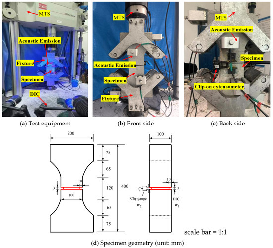
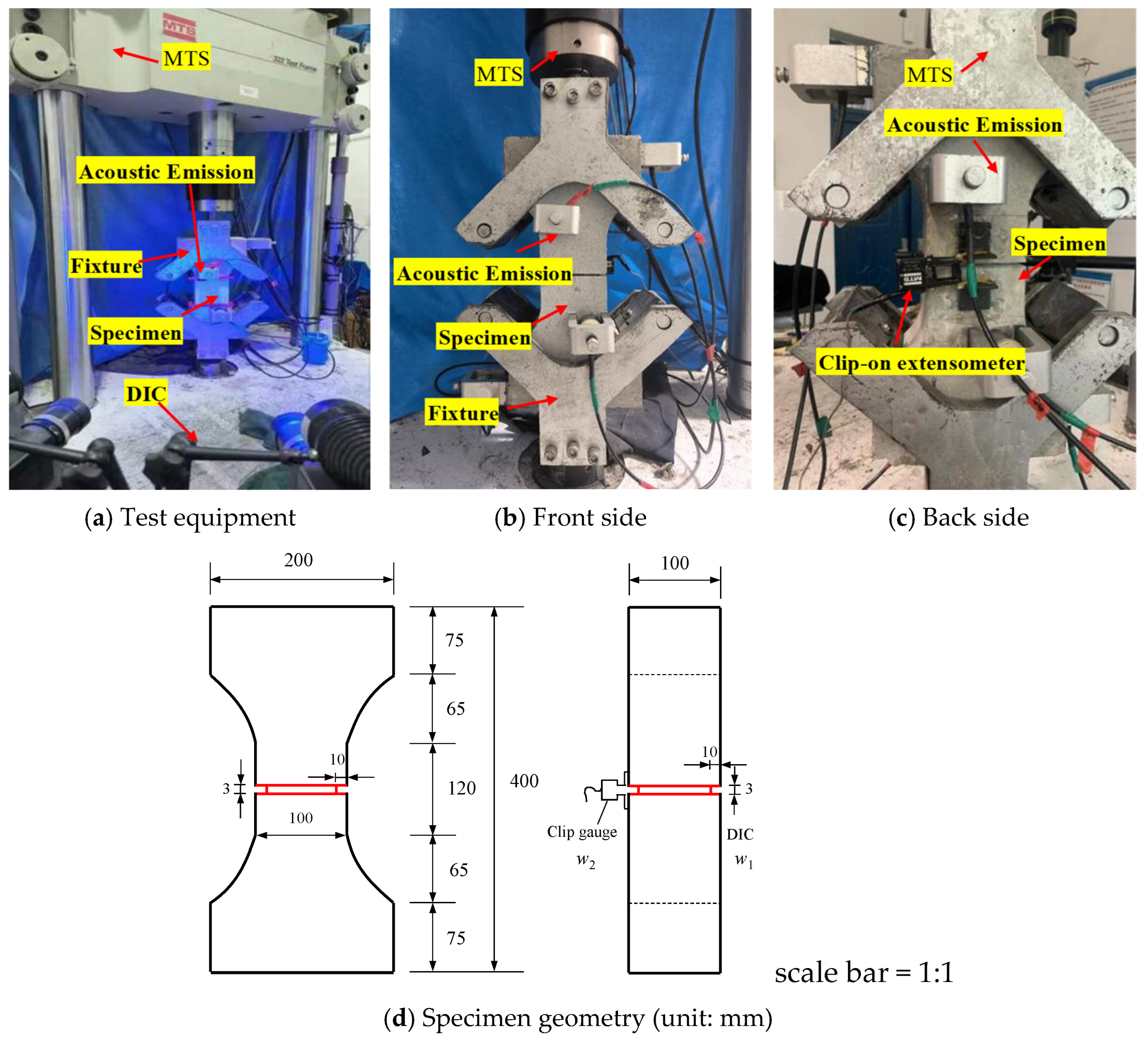
Figure 4.
Steel fiber concrete uniaxial tensile stress–crack width test device and specimen geometry.
The full axial tensile stress–crack width curve test for Steel-Fiber-Reinforced Concrete (SFRC) was conducted using a 500 kN MTS322 multifunctional fatigue testing machine (MTS Systems Corporation, Eden Prairie, MN, USA). Crack width measurements were obtained through three-dimensional digital imaging technology (3D-DIC) and clip-on extensometers. The loading speed during the test was set to 0.001 mm/s.
During the test, the load was recorded by the MTS system. The crack width on the front side was captured using the 3D-DIC system. In addition, during the test, the start and end times of MTS loading and DIC recording shall be kept consistent. The crack width on the back side (as shown in Figure 4c) was measured using clip-on extensometers, which dynamically collected data. An acoustic emission device was employed to capture signals generated during the formation and propagation of microcracks. A pre-test was conducted to check for eccentricity. The pre-tension load was set at approximately 15% to 20% of the failure load.
Prior to loading, an eccentricity check shall be conducted for the test. A pre-tension of approximately 15% of the failure load is applied, and the measured crack width values on both sides are observed to ensure that the eccentricity ratio does not exceed 15%. If not, the centering shall be re-performed. The eccentricity ratio is calculated according to the following formula:
where ew is the eccentricity rate of the specimen under tensile load, and w1 and w2 are the crack widths (mm) on both sides of the specimen.
A notch was introduced at the midsection of the axial tensile specimen, with a depth of 10 mm and a width of 3 mm, and the gauge length of the specimens is 100 mm. The test setup for the axial tensile stress–crack width measurement, along with the geometric dimensions of the specimen, is shown in Figure 4. When calculating the axial tensile stress, the cross-sectional area adopted is that at the dog-bone notch section. Since the notch depth is 10 mm, the cross-sectional dimensions shall be taken as 80 × 80 mm2. If the specimen fractures outside the pre-cut notch, the test results are deemed invalid. The formula for calculating the axial tensile stress of SFRC is as follows:
where σft is the axial tensile stress (MPa), F is the applied load (N), and An is the cross-sectional area of the specimen (mm2).
3. Results and Discussion
Dog-bone specimens were used in the axial tensile tests to obtain the axial tensile stress–crack width curves for SFRC. The axial tensile stress is calculated by dividing the tensile load by the net cross-sectional area. The crack width was measured using three-dimensional digital imaging technology (3D-DIC) and clip-on extensometers.
3.1. Number of Hooks on Steel Fibers
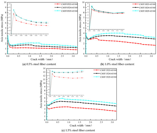
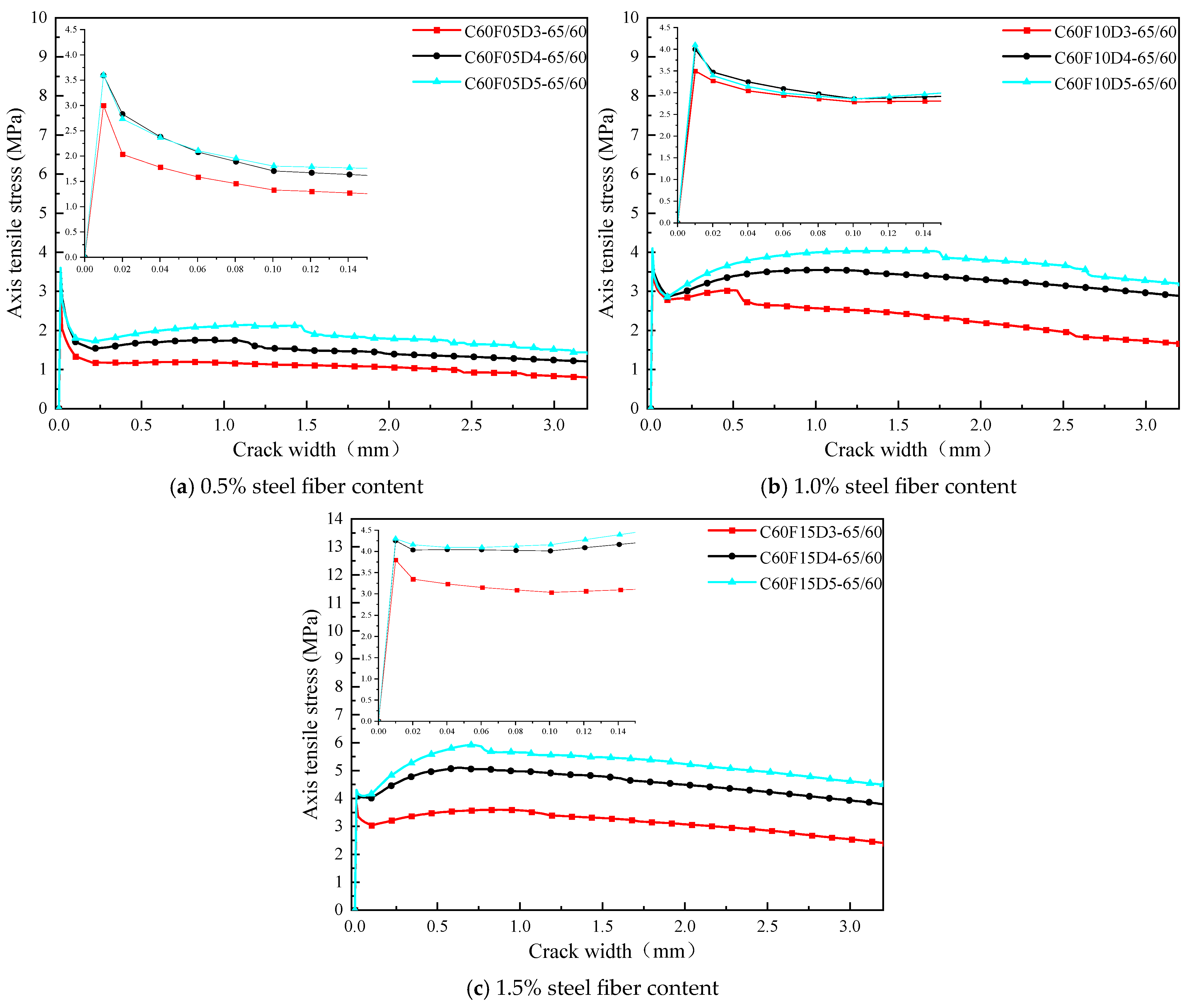
Figure 5a illustrates the influence of different types of steel fibers (3D, 4D, and 5D) on the σ-w curves for SFRC. These specimens had a concrete strength of C60, a steel fiber volume fraction of 0.5%, and an aspect ratio of 65. As seen in the figure, the peak stress of SFRC increases with the number of hooks on the steel fibers. However, the number of hooks has little effect on the slope of the ascending segment. After the peak point, all three curves exhibit a softening phenomenon, which is due to the rapid decrease in the mechanical interlocking force of the concrete after cracking, while the bridging effect of the steel fibers is still relatively weak. Subsequently, the steel fibers start to bridge the cracks, and the bridging stress increases with the number of hooks, as the increase in hooks enhances the mechanical anchoring effect of the steel fibers.
Figure 5.
Uniaxial tensile stress–crack width curve of steel fiber concrete with different numbers of steel fiber hooks.
Similarly, Figure 5b and Figure 5c present the test results for specimens with steel fiber volume fractions of 1.0% and 1.5%, respectively. The peak stress also increases with the number of hooks on the steel fibers. For specimens with 4D and 5D steel fibers and a volume fraction of 1.5%, strain hardening is observed.
3.2. Volume Fraction of Steel Fibers
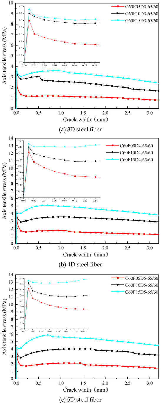
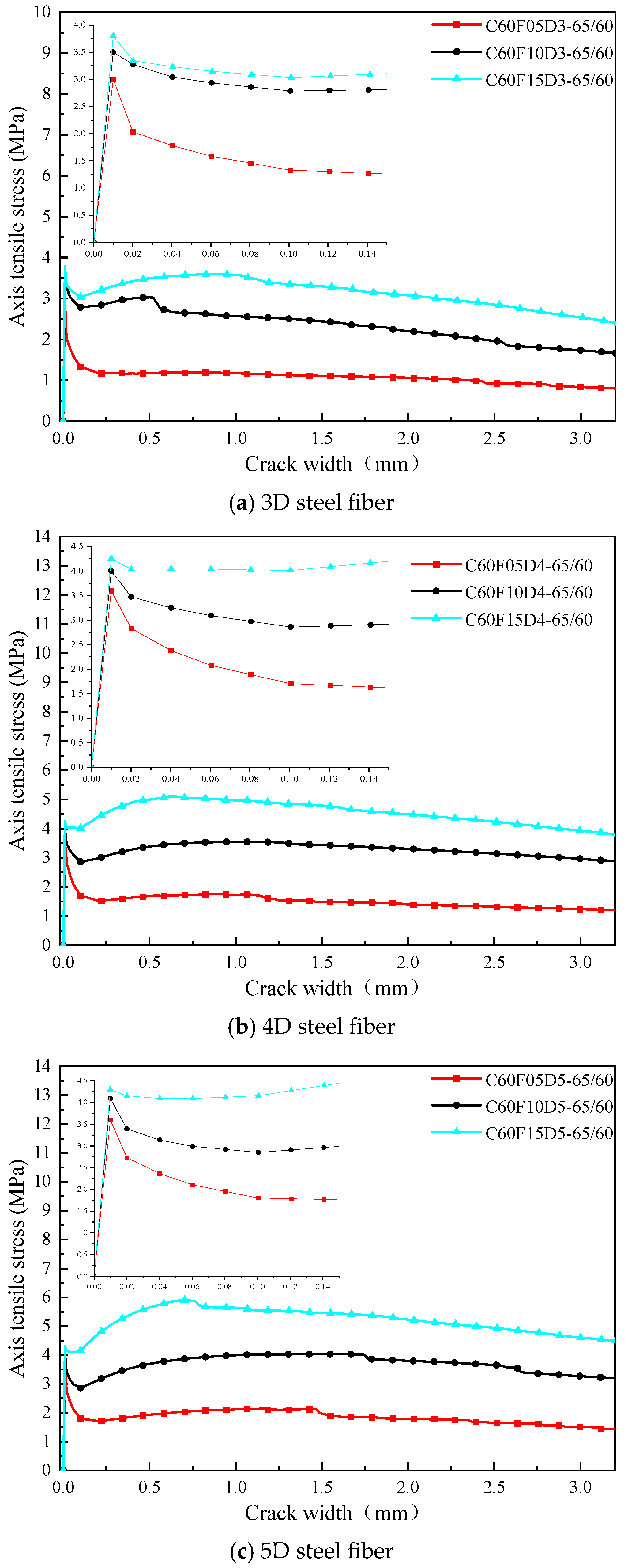
Figure 6a shows the influence of different steel fiber volume fractions (0.5%, 1.0%, and 1.5%) on the σ-w curves. These specimens had a concrete strength of C60, 3D steel fibers, and an aspect ratio of 65. As shown in the figure, the peak stress of SFRC increases with the volume fraction of steel fibers, while the slope of the ascending segment changes insignificantly. After the peak point, all three curves exhibit a softening phenomenon, but different volume fractions result in varying degrees of softening. The higher the volume fraction of steel fibers, the weaker the degree of softening. This is because an increase in the volume fraction increases the number of steel fibers crossing the crack surface, thereby enhancing the bridging effect of the steel fibers.
Figure 6.
Uniaxial tensile stress–crack width curves of SFRC with different steel fiber volume fractions.
Similarly, Figure 6b and Figure 6c present the test curves for dog-bone specimens with 4D and 5D steel fibers, respectively. The peak stress also increases with the volume fraction of steel fibers. The increase is greater for 5D steel fibers than for 4D steel fibers, and greater for 4D steel fibers than for 3D steel fibers.
3.3. Aspect Ratio of Steel Fibers
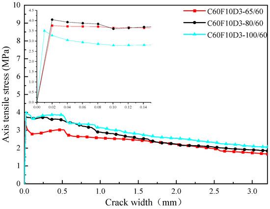
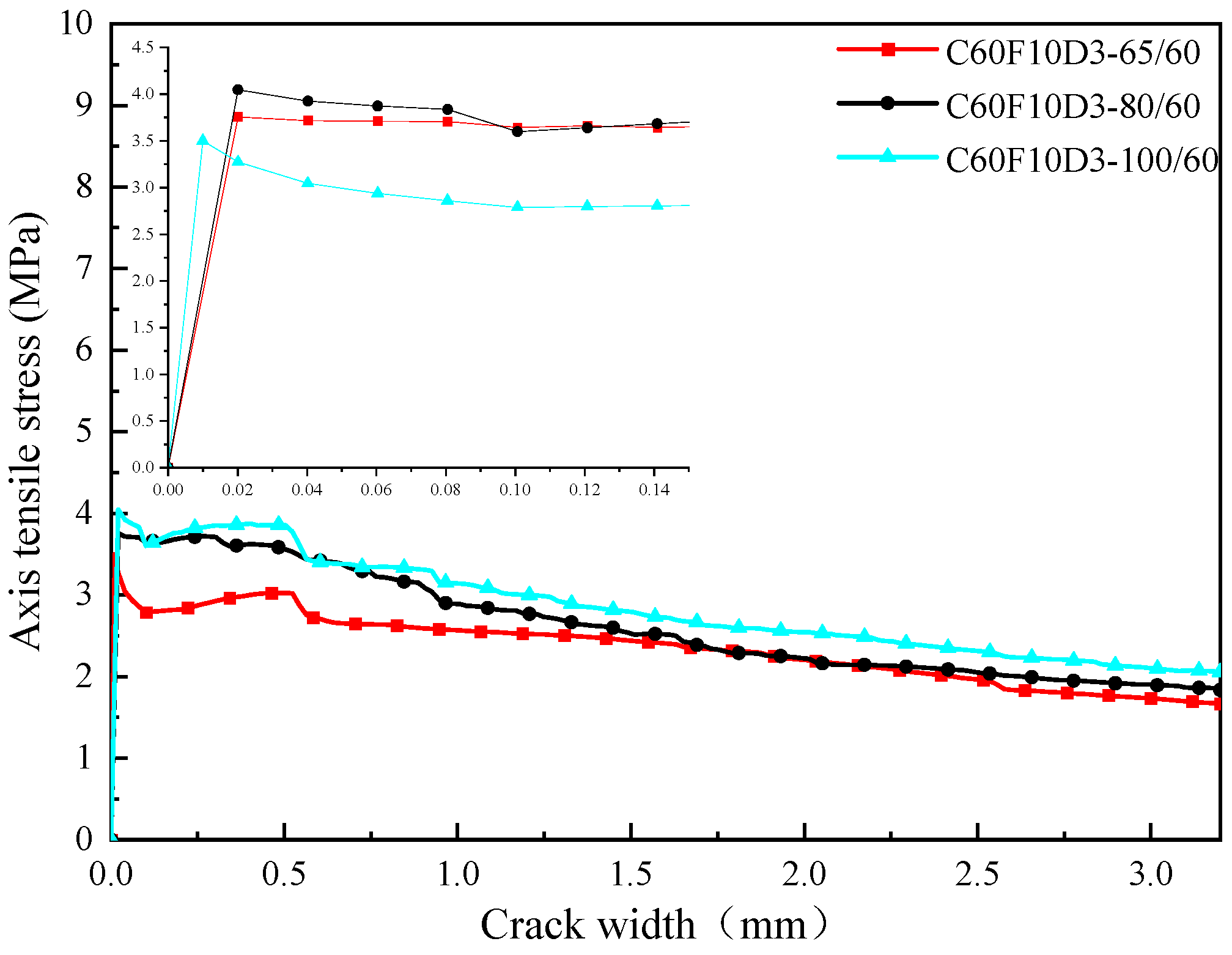
Figure 7 illustrates the influence of different steel fiber aspect ratios (65, 80, and 100) on the σ-w curves. These specimens had a concrete strength of C60, 3D steel fibers, and a volume fraction of 1.0%. As shown in the figure, the peak stress increases with the aspect ratio of the steel fibers. This is because a higher aspect ratio increases the number of steel fibers crossing the crack surface, thereby enhancing the bridging stress of the steel fibers. After the peak point, the three curves exhibit varying degrees of softening, and the residual strength slightly increases with the aspect ratio of the steel fibers.
Figure 7.
Uniaxial tensile stress–crack width curves of SFRC with different steel fiber aspect ratios.
3.4. Concrete Strength
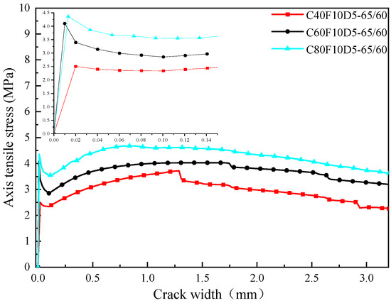
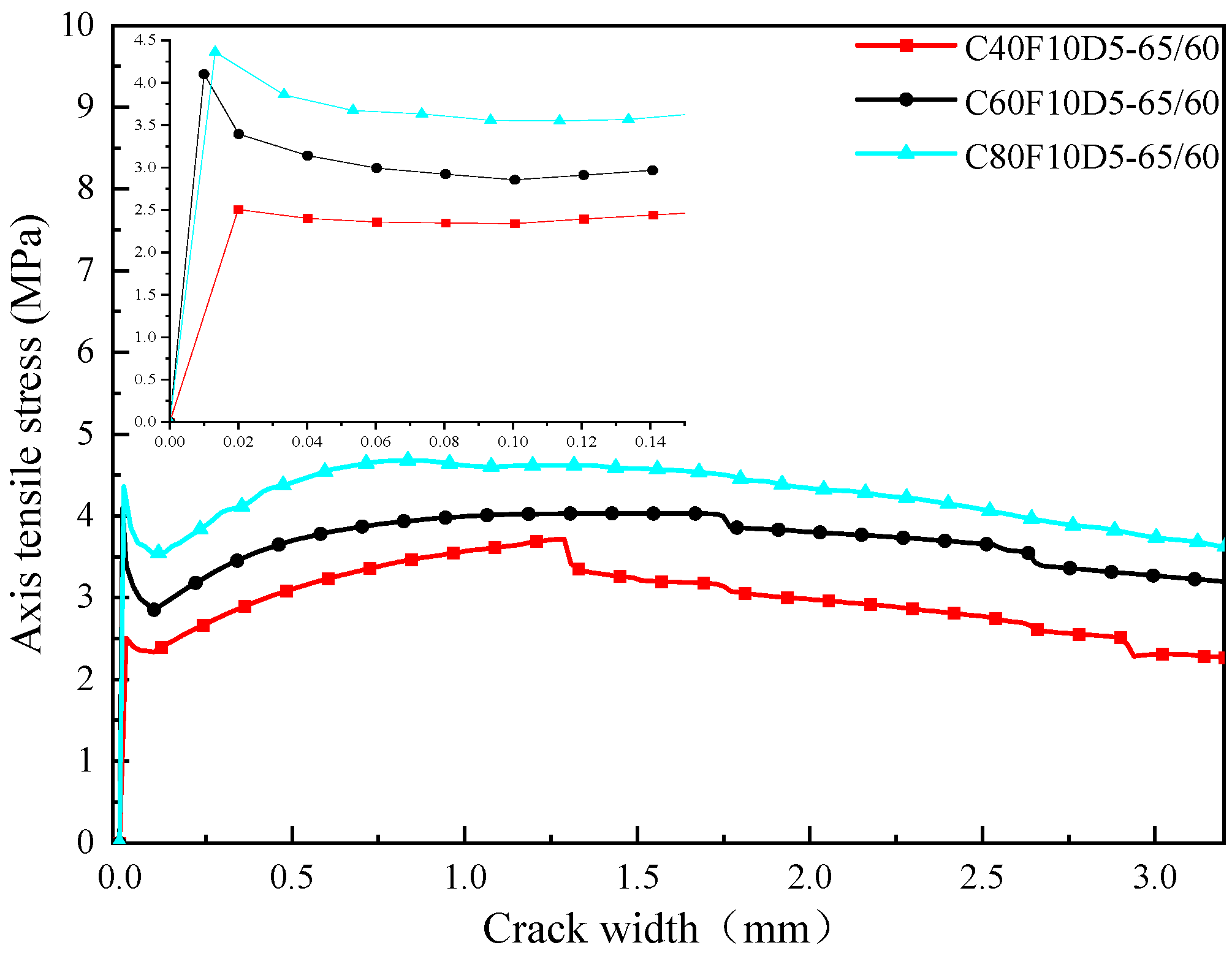
Figure 8 shows the influence of different concrete strengths (C40, C60, and C80) on the σ-w curves. These specimens used 5D steel fibers with a volume fraction of 1.0% and an aspect ratio of 65. As seen in the figure, the peak stress of SFRC increases with the concrete strength. This is because the increase in the matrix strength enhances the interfacial bond between the steel fibers and the concrete, as well as the mechanical anchorage effect of the hooked-end steel fibers, thereby increasing the total bridging stress of the steel fibers. After the peak point, the specimens with a higher concrete strength exhibit greater residual tensile stress.
Figure 8.
Uniaxial tensile stress–crack width curves of SFRC with different concrete strengths.
3.5. DIC-Based Analysis of Crack Evolution and Damage Progression
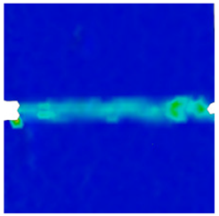
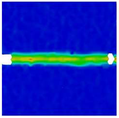
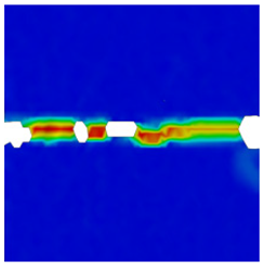
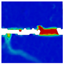
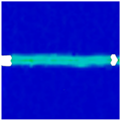
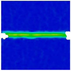
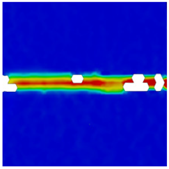
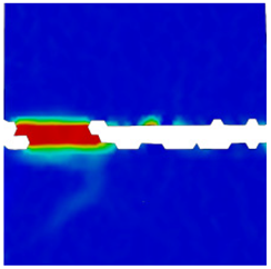
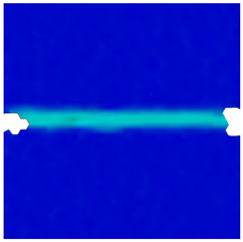
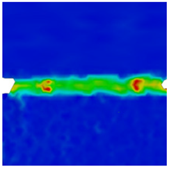
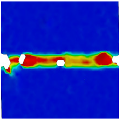
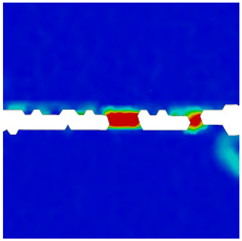
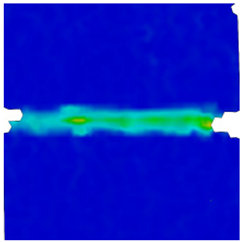
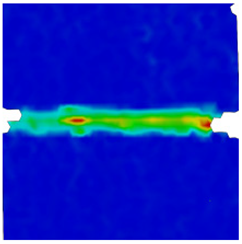
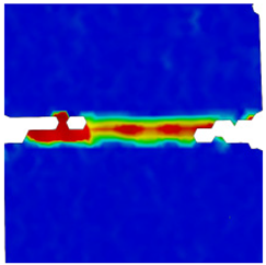
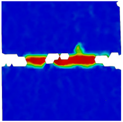
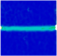
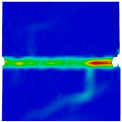
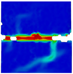
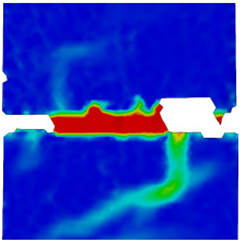
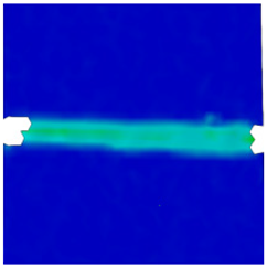
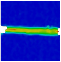
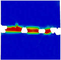
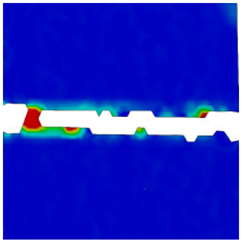
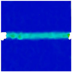
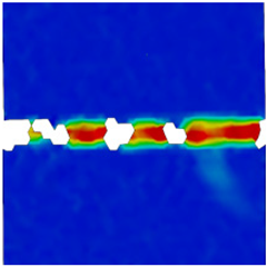
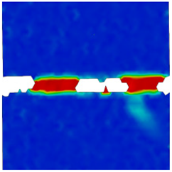
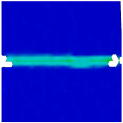
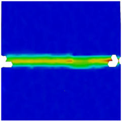
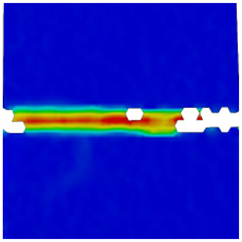
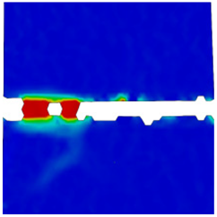
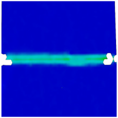
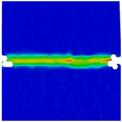
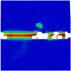
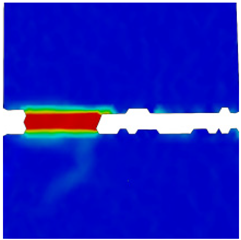
To investigate the effects of different parameters on the tensile performance and damage evolution of steel-fiber-reinforced concrete (SFRC) specimens under axial tension, the Digital Image Correlation (DIC) technique was employed to record the evolution of surface strain fields during the tensile failure process. The damage evolution of SFRC axial tensile specimens was divided into three stages. The DIC strain maps corresponding to the first peak load in Stage I, the second peak load in Stage II, a crack mouth opening displacement (CMOD) of 1.5 mm in Stage III, and a CMOD of 3.5 mm in Stage III were analyzed, as shown in Table 6.
Table 6.
Crack patterns and strain maps of SFRC axial tensile specimens at different stages.
As observed from Table 6, taking specimen C60F10D5-65/60 as an example, the specimen remained in the elastic deformation stage prior to reaching the first peak load, and no significant color variation was observed in the DIC strain maps. At the first peak load, initial cracks appeared uniformly at the notch, and the corresponding crack strain bands were characterized by a light green color. Subsequently, the specimen experienced initial cracking and entered the steel-fiber-reinforced stage, during which the applied load continued to increase. Meanwhile, the color of the crack strain bands gradually deepened, and yellow strain bands were observed at the second peak load. Thereafter, the specimen entered the softening stage. When the crack width reached 1.5 mm, a small number of blank fractured regions appeared, indicating that the crack width was too large to be captured by the DIC system. At this stage, the crack strain bands exhibited a dark red color. When the crack width further increased to 3.5 mm, secondary crack bands could be observed, while a large number of blank fractured regions appeared along the main crack band. At this point, the concrete on both sides of the notch was nearly completely separated.
Taking specimen C60F10D5-65/60 as an example, a comparative analysis with two groups of specimens with different concrete strengths indicates that specimens with a lower concrete strength exhibit a larger number of white fractured zones, reflecting a more severe degree of damage. In contrast, specimens with a higher concrete strength show more pronounced secondary crack bands, a greater number of surface cracks, and an enhanced deformation capacity.
A comparison between two groups of specimens with different steel fiber contents reveals that specimens with a steel fiber volume fraction of 1.5% exhibit clearly developed secondary crack bands. In these specimens, surface concrete spalling is the most severe, and the fracture energy accumulated at the notch is redistributed over the specimen surface. Even at a CMOD of 3.5 mm, the main crack band remains clearly visible, indicating that the overall deformation capacity of SFRC increases with increasing fiber content.
For specimens reinforced with different types of steel fibers, at a CMOD of 3.5 mm, the color of the main crack band in specimens containing 3D steel fibers almost entirely turns white, and no secondary crack bands are observed, indicating the severe damage of SFRC. In contrast, the evolution of strain bands in specimens reinforced with 4D steel fibers is similar to that of specimens with 5D steel fibers. This suggests that, compared with 3D steel fibers, 4D and 5D steel fibers provide a more significant enhancement in the tensile performance of SFRC.
A comparison between two groups of specimens with different steel fiber aspect ratios shows no significant differences in the strain bands. This indicates that varying the aspect ratio of steel fibers in SFRC has a negligible effect on the evolution of the surface strain field and crack patterns during tensile loading.
4. Uniaxial Tensile Stress–Crack Width Relationship for Multiple Hooked-End Steel-Fiber-Reinforced Concrete
The test results for the axial tensile strength, peak stress, and residual axial tensile strength of concrete reinforced with multi-end hooked steel fibers are presented in Table 7, wherein ft,SFRC denotes the axial tensile strength; ft,0 denotes the peak stress; and fr,1, fr,2, and fr,3 represent the residual axial tensile strengths corresponding to the crack widths w of wt,0, wt,0 + 0.1 mm, 1.5 mm, and 3.5 mm, respectively, on the axial tensile σ-w curve.
Table 7.
Test results of axial tensile strength, peak stress, and residual axial tensile strength of SFRC.
4.1. Basic Assumptions of the Model
4.1.1. Matrix Assumptions
- (1)
- Ordinary concrete bears the primary tensile stress prior to cracking.
- (2)
- The incorporation of steel fibers weakens the continuity of the concrete matrix, and the degree of weakening increases with increasing fiber volume fraction Vf, aspect ratio Lf/df, and the number of hooked ends nh [37].
- (3)
- The contribution of the matrix can be expressed using an exponential decay function to characterize the influence of interfacial disturbance.
4.1.2. Fiber Bridging Assumptions
- (1)
- After crack initiation, steel fibers provide bridging stress through anchorage effects induced by the hooked ends.
- (2)
- The bridging stress is proportional to the fiber content (volume fraction Vf), fiber aspect ratio Lf/df, and the number of hooked ends nh.
- (3)
- With increasing crack width, the bridging stress exhibits an exponential decay behavior.
4.1.3. Fiber Orientation Assumption
The three-dimensional random distribution of fibers is accounted for by introducing an orientation efficiency coefficient η0.
4.1.4. Total Uniaxial Tensile Strength Assumption
The axial tensile strength is obtained by the superposition of the matrix contribution and the fiber bridging contribution [38], expressed as follows:
4.2. Matrix Contribution Model
4.3. Multiple Hooked-End Steel Fiber Bridging Model
Building upon the existing σ-w relationship studies, the post-cracking bridging stress of steel-fiber-reinforced concrete (SFRC) depends on the fiber volume fraction and geometric parameters. Ding and Li [37,38] established the σ-w relationship and performed regression analysis for 3D/4D/5D steel fibers in SFRC, demonstrating that the peak bridging stress is closely related to the fiber parameters, which can be used for the calibration of the bridging coefficient parameters in this study. Based on this foundation, a new multi-end hooked fiber bridging model is proposed in this work:
where σ0 is the reference bridging coefficient; nh is the number of hooked ends of the multi-end hooked steel fibers; Vf is the steel fiber volume fraction; Lf/df is the fiber aspect ratio; λ is the crack propagation attenuation coefficient; w is the crack width; and df is the steel fiber diameter.
Based on Equations (3)–(5), the axial tensile strength ft,SFRRC of SFRC can be expressed as follows:
This expression can be further simplified as follows:
where A, B, C, D, and E are regression coefficients, which can be obtained by fitting Equation (7) to the axial tensile test results listed in Table 5. For the axial tensile strength of SFRC, the calibrated values are A = −11.9548, B = −0.2584, C = 1.1169, D = −0.9505, and E = 3.6758, with a coefficient of determination R2 = 0.8700, and RMSE = 0.2664.
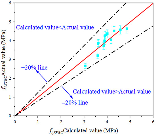
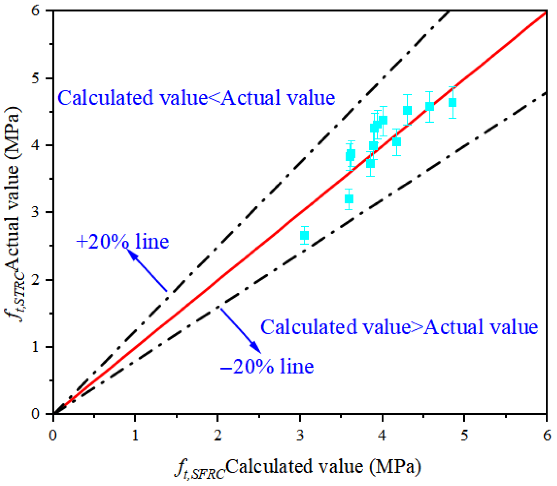
A comparison between the calculated axial tensile strength of SFRC using Equation (7) and the experimental results is presented in Figure 9. As shown in the figure, the coordinates of all predicted and experimental values fall within a deviation of ±20%, which verifies the accuracy and reliability of Equation (7).
Figure 9.
Comparison between calculated and experimental axial tensile strengths of SFRC.
4.4. Four-Segment Uniaxial Tensile Stress–Crack Width Constitutive Model
Based on the characteristics of the uniaxial tensile stress–crack width (σ-w) curves, the incorporation of multi-end hooked steel fibers effectively prevents the brittle failure behavior of SFRC immediately after first cracking. As a result, a secondary ascending branch (steel-fiber-reinforced stage) and a gradual descending branch (softening stage) are observed in the σ-w curve. When the crack width reaches 1.5 mm (corresponding to an ultimate strain of approximately 1.5%), SFRC is still able to maintain a relatively high axial tensile stress. According to the Chinese code [38], the ultimate tensile strain of ordinary concrete is approximately 0.08% (corresponding to a crack width smaller than 0.1 mm), which is significantly lower than the ultimate tensile strain of SFRC (about 1.5%).
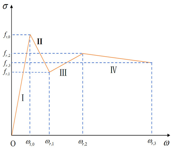
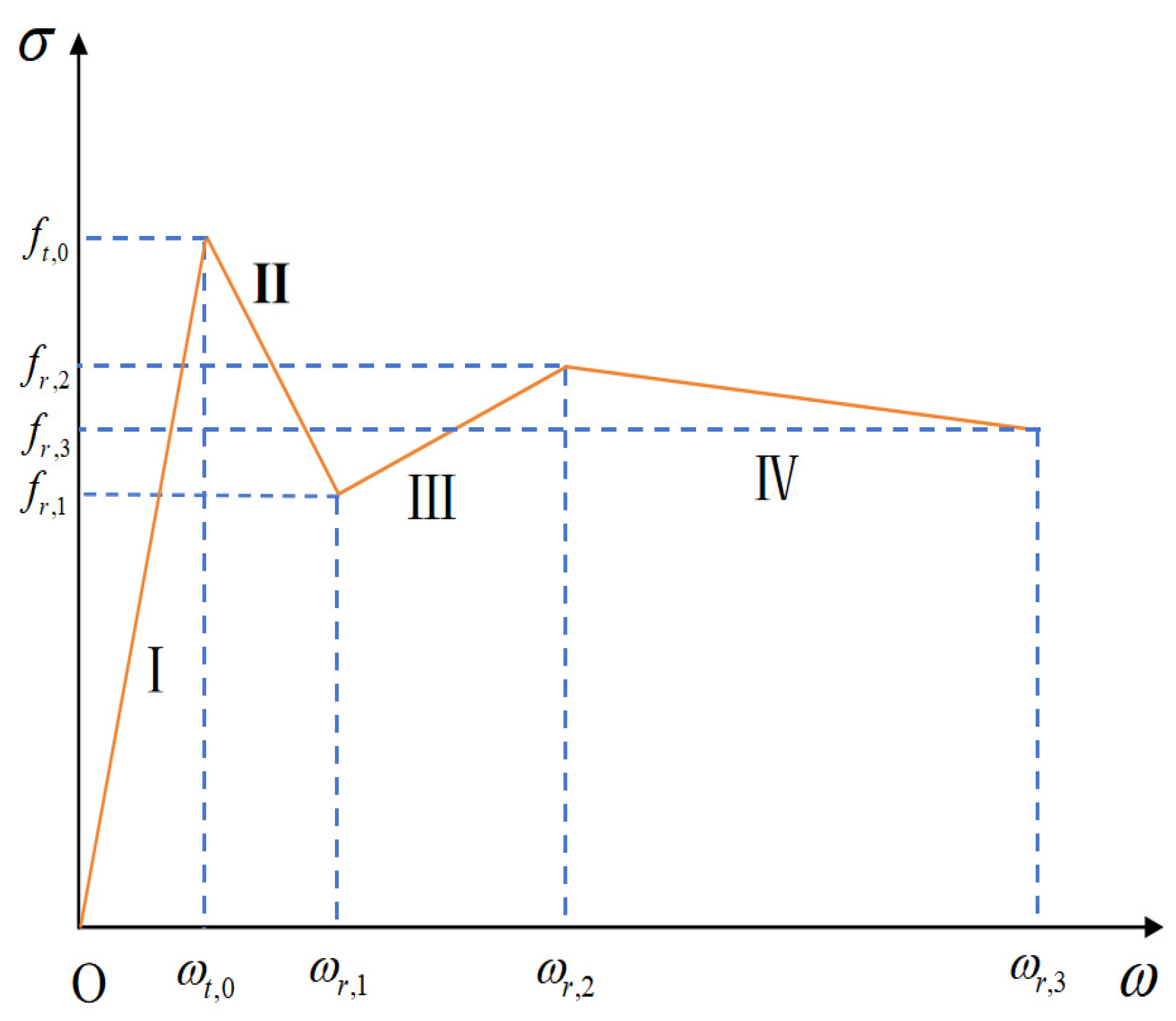
Based on the experimental results, the uniaxial tensile σ-w curve of SFRC can be divided into four distinct stages: the elastic ascending stage (Stage I, as shown in Figure 10), the rapid descending stage associated with crack initiation (Stage II), the secondary ascending stage governed by steel fiber reinforcement (Stage III), and the gradual descending stage corresponding to material softening (Stage IV). Accordingly, a four-segment constitutive model is proposed to describe the axial tensile σ-w relationship of SFRC, as illustrated in Figure 10. The corresponding expressions are given as follows:
where ft,0 and wt,0 denote the peak tensile stress and the corresponding crack width of multi-end hooked steel-fiber-reinforced concrete, respectively; fr,1, fr,2, and fr,3 represent the residual axial tensile strengths; and wr,1, wr,2, and wr,3 are the crack widths corresponding to the residual tensile strengths.
Figure 10.
Axial tensile σ-w constitutive model of multi-end hooked steel-fiber-reinforced concrete.
According to the analysis of the experimental axial tensile σ-w curves of SFRC, the characteristic crack widths are selected as wr,1 = wt,0 + 0.1 mm, wr,2 = 1.5 mm, and wr,3 = 3.5 mm. After concrete cracking, the peak tensile stress ft,0 and the residual axial tensile strengths fr,1, fr,2, and fr,3 in Equation (8) are affected by the same parameters governing the axial tensile strength. These parameters can be calculated using Equations (9)–(12), respectively:
where ft,0 is the axial tensile strength of ordinary concrete; Vf is the steel fiber volume fraction (Vf = 0%–1.5%); λn is the steel fiber shape factor (λn); Lf/df is the fiber aspect ratio; w is the crack width; df is the steel fiber diameter; and Ai, Bi, Ci, Di, Ei (i = 0, 1, 2, 3), which can be obtained by fitting Equations (9)–(12) to the axial tensile test results listed in Table 7. They are regression coefficients for the peak tensile stress and residual axial tensile strengths. These coefficients were obtained by fitting the experimental results and are listed in Table 8.
Table 8.
Regression coefficients for peak tensile stress and residual axial tensile strength of SFRC axial tensile specimens.
The selected transition crack widths are wr,1 = wt,0 + 0.1 mm, wr,2 = 1.5 mm, and wr,3 = 3.5 mm, respectively. The determination of these values is a comprehensive consideration of experimental observations, the characteristic inflection points of the tensile stress–crack width curves, and consistency with the crack width ranges reported in existing studies on steel-fiber-reinforced concrete. For example, early analytical tensile stress–crack width (σ-w) models for multi-hooked steel fibers have indicated that the different stages of tensile performance correspond to the changes in fiber engagement and pullout mechanisms, which provides a basis for the adoption of multiple transition points in the constitutive description [36]. Similar transition concepts are also introduced in the semi-empirical constitutive models for fibrous concrete, and these concepts are correlated with the changes in bridging stress and slip behavior across cracks. In addition, micromechanical studies on fiber pullout reveal the evolution law of fiber–matrix interfacial behavior with the crack opening, which provides mechanical mechanism support for associating transition crack widths with dominant damage mechanisms such as initial cracking, interfacial debonding, and fiber pullout [39,40]. In addition, the moment of the first peak load in Stage I, the moment of the second peak load in Stage II, and the moment when the crack mouth opening displacement (CMOD) reaches 3.5 mm in Stage III in the digital image correlation (DIC) measurements correspond to wt,0, wr,1, and wr,3 = 3.5 mm, respectively.
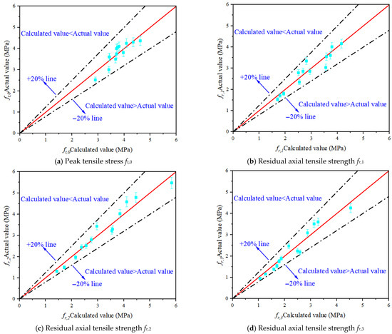
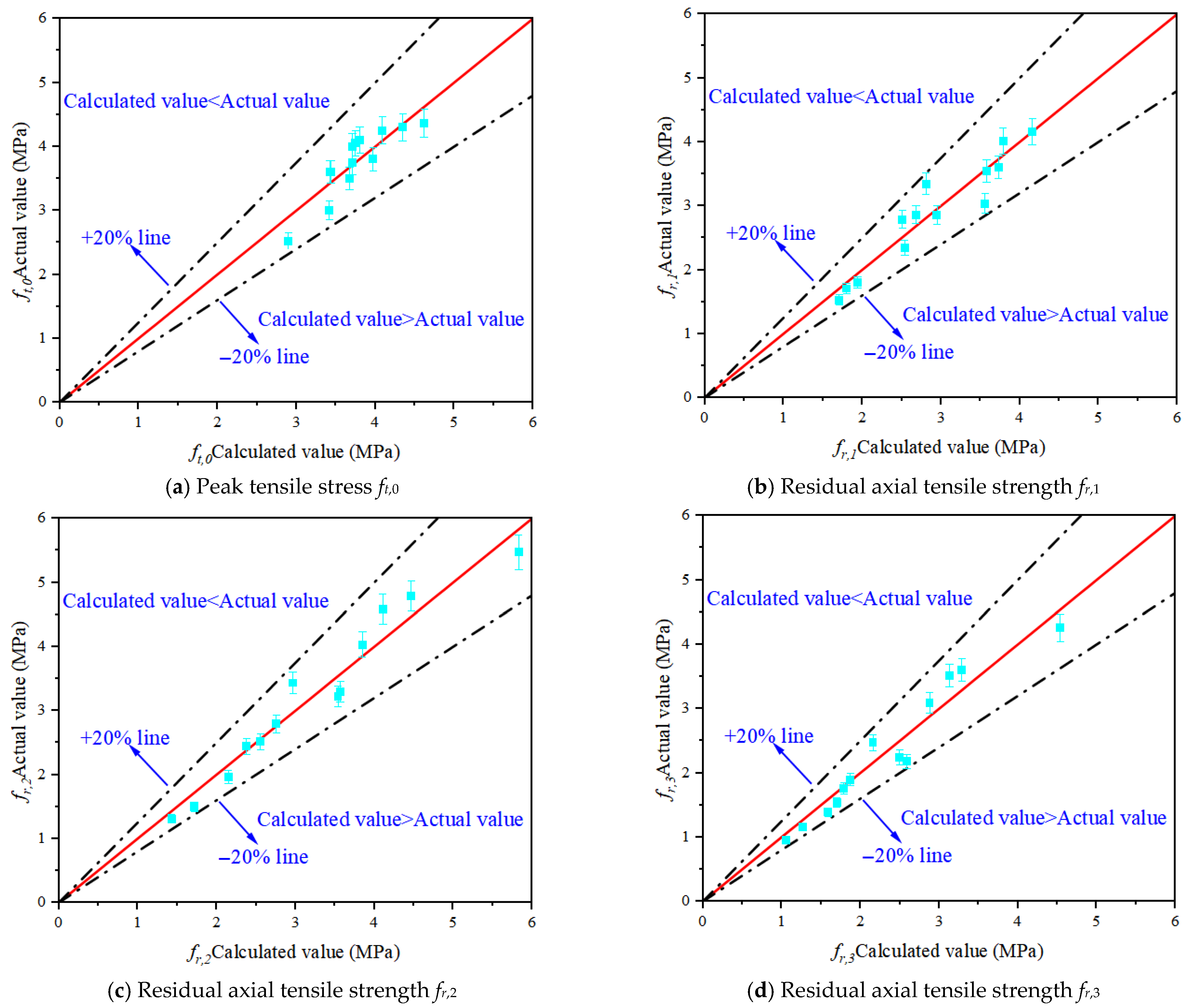
Based on the results listed in Table 8, the axial tensile strengths at the key points of the SFRC σ-w curve were calculated using Equations (9)–(12). A comparison between the calculated and experimental values is shown in Figure 11. It can be observed that the calculated values agree well with the experimental results, verifying the accuracy of the proposed calculation method.
Figure 11.
Comparison between calculated and experimental values of peak tensile stress and residual axial tensile strength of SFRC.
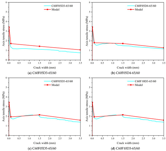
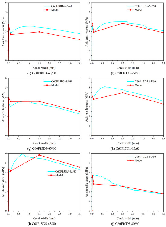
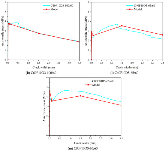
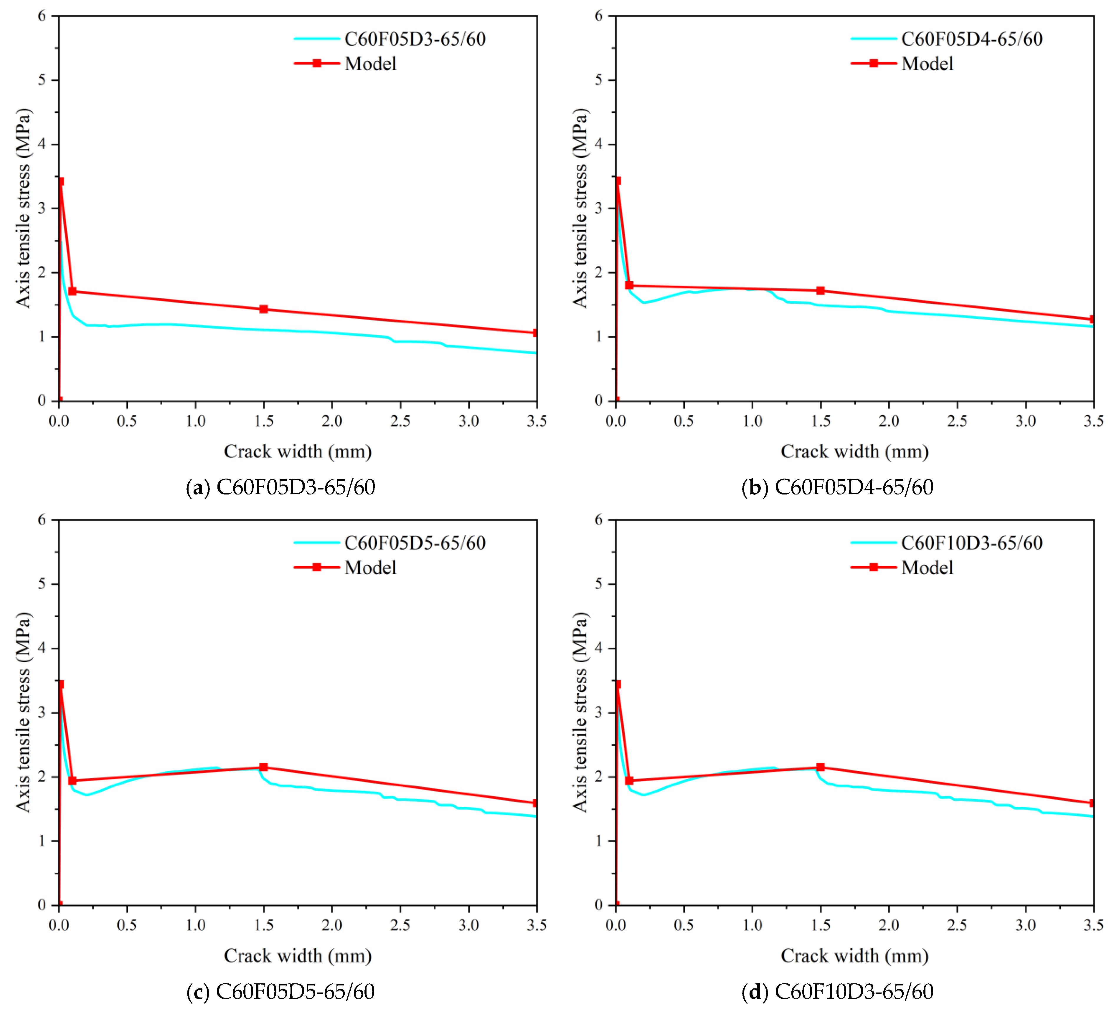
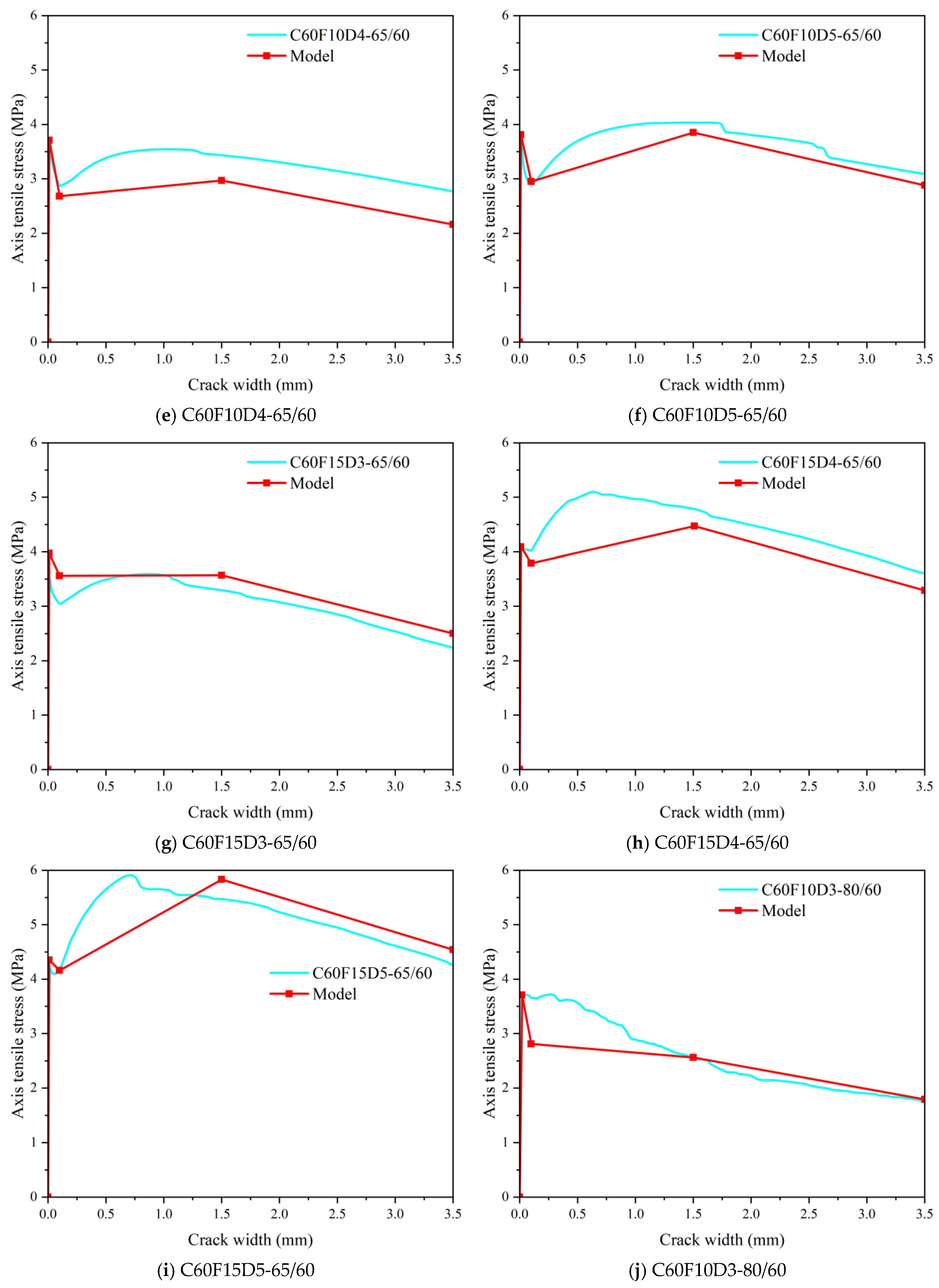
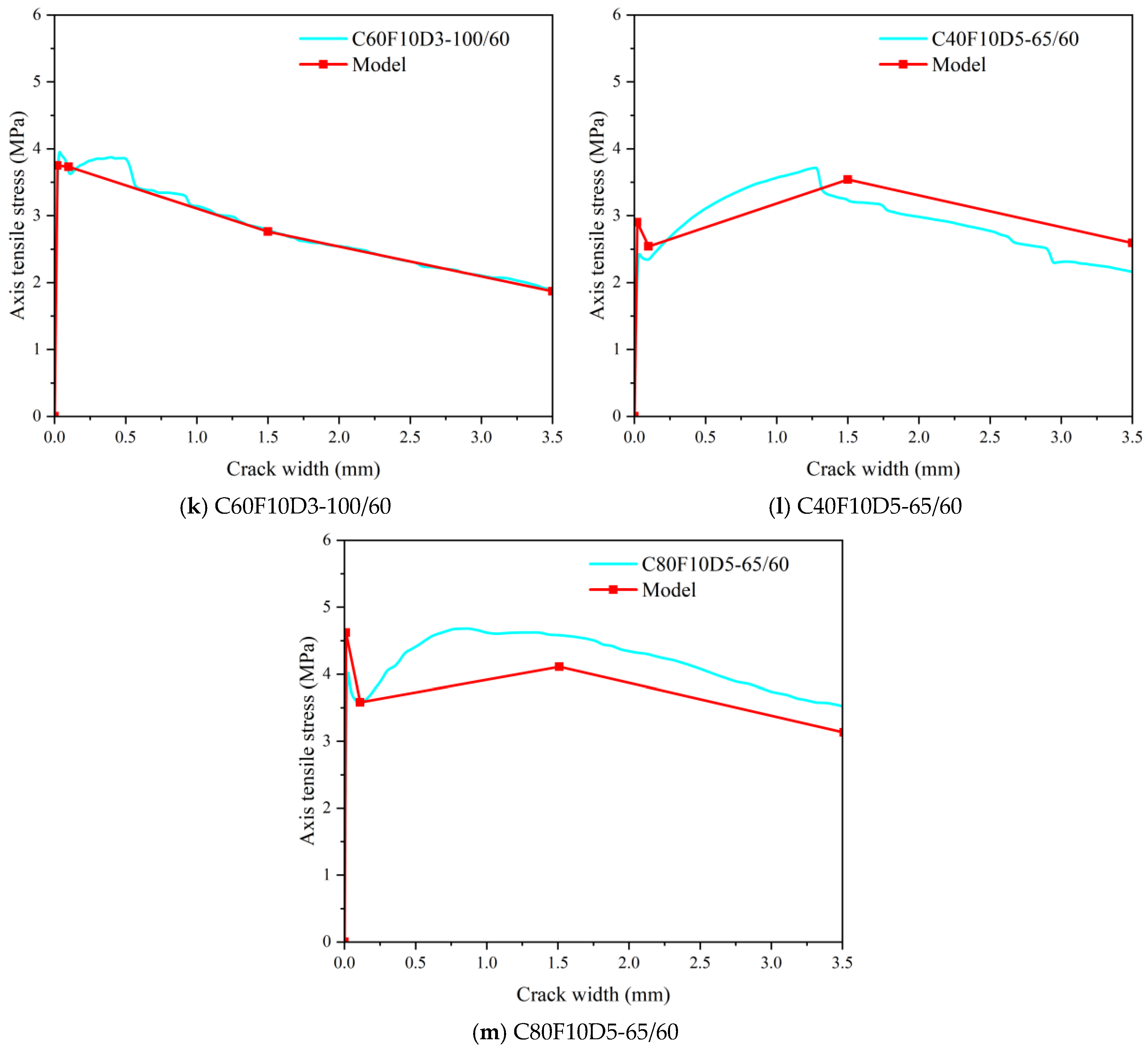
Based on Equation (8), the four-segment axial tensile σ-w curves of SFRC were obtained. A comparison between the calculated σ-w curves and the experimental results is presented in Figure 12. It can be seen that the calculated results exhibit a consistent variation trend with the experimental curves, which further verifies the feasibility of Equation (8) for predicting the axial tensile σ-w constitutive behavior of SFRC.
Figure 12.
Axial tensile σ-w constitutive relationships of multi-end steel-fiber-reinforced concrete.
4.5. Limitations of the Four-Segment Uniaxial Tensile Stress–Crack Width Constitutive Model
Despite the good agreement observed between the experimental results and model predictions within the investigated parameter ranges, several limitations of the proposed constitutive model should be acknowledged. The empirical coefficients in the four-segment formulation were calibrated based on a specific range of concrete compressive strength, steel fiber volume fraction, fiber aspect ratio, and hook configurations. Consequently, the applicability of the model is primarily confined to the parameter domains validated by the experimental program.
When the model is extrapolated beyond these ranges, increased uncertainty may arise due to potential changes in the dominant damage and load-transfer mechanisms. For example, at higher fiber contents or different fiber geometries, fiber rupture or alternative pullout behaviors may become significant, which are not explicitly accounted for in the current formulation. In addition, variations in the matrix properties or fiber–matrix interfacial characteristics may further influence the post-cracking response.
Therefore, predictions obtained outside the validated parameter ranges should be interpreted with caution. Future studies incorporating broader material properties and fiber configurations are recommended to further extend and generalize the proposed model.
5. Model Application in Structural Design
5.1. Design Calculation Procedure
The proposed five-end-hook steel-fiber-reinforced concrete model can be directly applied in the structural design to evaluate the tensile and post-cracking behavior of SFRC members. The design procedure consists of the following steps.
First, the steel fiber parameters, including the fiber type, volume fraction Vf, and geometric characteristics, are selected according to the recommendations given in Table 5. Second, the tensile strength of the concrete matrix ft is determined from material tests or code-based expressions.
After cracking, the fiber bridging stress σ(w) corresponding to a given crack width w is calculated using the proposed exponential softening relationship:
σ(w) = σ0 exp(−λw)
The residual tensile strength of SFRC, fr, is then obtained by superposing the matrix contribution and the fiber bridging contribution:
fr = ft + Σ σ(wi) Af
Finally, the calculated residual tensile strength is verified against the requirements specified in relevant design codes, such as EN 14651 and ACI 318, to ensure compliance with serviceability and safety criteria.
5.2. Design Example
To illustrate the application of the proposed model, an SFRC beam with the following parameters is considered:
- Concrete tensile strength: ft = 4.25 MPa;
- Steel fiber volume fraction: Vf = 1.0%;
- Fiber geometry: Lf/df = 65 (five-end-hook fibers).
Based on the recommended parameters, the fiber bridging stress is expressed as follows:
σ(w) = 1.2 exp(−2.0w)
Using the above relationship, the residual tensile strength fr is calculated and compared with the corresponding code-specified limits. The results confirm that the proposed model provides a sufficient post-cracking tensile capacity to satisfy the design requirements.
5.3. Finite Element Analysis
The proposed constitutive relationship can be readily implemented in finite element software for the nonlinear analysis of SFRC structures. Owing to the simple exponential stress–crack width formulation, the model offers a high computational efficiency while accurately capturing the post-cracking tensile behavior, making it suitable for large-scale structural simulations.
5.4. Comparison with Design Codes
To verify the applicability and safety of the proposed model, the calculated residual tensile strength (fr) is compared with the minimum values specified in the established design codes for SFRC, particularly EN 14651 and ACI 318 [40,41]. These comparisons ensure that the model’s predictions align with the widely accepted standards for both serviceability and ultimate limit states.
- (1)
- EN 14651
According to EN 14651, the residual tensile strength requirements are defined as follows:
- -
- fr1 (crack width = 0.5 mm) ≥ 0.7ft
- -
- fr3 (crack width = 2.5 mm) ≥ 0.5ft
For a concrete matrix tensile strength ft = 4.25 MPa, the minimum required residual strengths are as follows:
- -
- fr1 ≥ 2.98 MPa
- -
- fr3 ≥ 2.13 MPa
The proposed model predicts the residual strengths of approximately 3.70 MPa at fr1 and 3.66 MPa at fr3, which both exceed the EN 14651 requirements.
- (2)
- ACI 318
ACI 318 specifies that the residual tensile strength of SFRC should satisfy the minimum limits for crack control and structural integrity:
- -
- Residual tensile strength ≥ 0.5ft for serviceability
- -
- Post-cracking tensile strength ≥ 0.7ft for ultimate limit states
For ft = 4.25 MPa, the corresponding limits are 2.13 MPa and 2.98 MPa, respectively. The model predictions satisfy both criteria, confirming their compliance with ACI 318.
6. Conclusions
This study focuses on the uniaxial tensile stress–crack width relationship of SFRC, deeply explores the influence of the number of hooks, volume fraction, aspect ratio of steel fibers, and concrete strength on its performance, and proposes a model based on the influence of different parameters. The main conclusions are as follows:
- (1)
- The uniaxial tensile strength of concrete specimens reinforced with 4D and 5D steel fibers is higher than that of specimens reinforced with 3D steel fibers. In general, steel-fiber-reinforced concrete (SFRC) exhibits strain-softening behavior; however, when the volume fraction of 4D and 5D steel fibers reaches 1.5%, a distinct strain-hardening response is observed. For SFRC reinforced with 4D/5D steel fibers at a volume fraction of 1.5%, the strain-hardening behavior originates from the synergistic interaction between the steel fibers and the concrete matrix. At this dosage, the spatial distribution density of fibers satisfies the crack-bridging requirement, while the hooked and anchored end configuration of 4D/5D steel fibers significantly enhances the interfacial bond strength with the matrix. After the crack initiation in the matrix, the fibers provide sustained bridging stress through the elastic stretching, frictional sliding, and mechanical interlocking of the hooked ends, effectively restraining the crack propagation and redistributing the tensile stress. Consequently, the specimens are able to maintain a relatively high load-carrying capacity beyond the peak stress with increasing strain, resulting in a typical strain-hardening behavior.
- (2)
- The uniaxial tensile σ-w response of SFRC is strongly affected by the concrete strength, steel fiber volume fraction, number of hooked ends, and fiber aspect ratio. With increasing values of these parameters, the σ-w curves become fuller and more ductile, exhibiting an enhanced post-cracking tensile capacity. Increasing the matrix strength from C40 to C60 and C80 results in tensile strength increases of 62.70% and 73.02%, respectively. Increasing the fiber volume fraction from 0.5% to 1.0% and 1.5% improves the tensile strength by 13.89% and 19.44%. Compared with 3D fibers, 4D and 5D fibers enhance the tensile strength by 14.29% and 17.14%, respectively, while increasing the fiber aspect ratio from 65/60 to 80/60 and 100/60 leads to strength gains of 7.14% and 15.71%. The influence of steel fibers is mainly manifested in the fiber-strengthening and softening stages, where fiber-related parameters directly govern the evolution of the σ-w curve.
- (3)
- At the micromechanical level, the tensile behavior of SFRC is governed by the transition of the load transfer from the concrete matrix to steel fibers after cracking. Multi-hooked steel fibers provide bridging stress through elastic stretching, interfacial friction, and mechanical anchorage at hooked ends. Compared with 3D fibers, 4D and 5D fibers exhibit stronger mechanical interlocking, delaying fiber pull-out. As the crack width increases, the effective embedment length and the number of fibers bridging the crack decrease, leading to a progressive degradation of bridging stress. This mechanism explains the observed four-stage σ-w response, and the proposed constitutive model provides a rational macroscopic representation of the underlying micromechanical behavior [39].
- (4)
- The comparison demonstrates that the proposed five-end-hook SFRC tensile model reliably meets or exceeds the residual strength requirements specified in EN 14651 and ACI 318. Therefore, the model is suitable for structural design applications and provides a practical tool for evaluating SFRC performance in both serviceability and ultimate limit states.
Author Contributions
Methodology, K.Z.; Software, Z.F.; Formal analysis, K.Z.; Resources, Zhe Fang; Writing—review & editing, D.G., C.D. and Z.F.; Supervision, D.G. and C.D.; Funding acquisition, D.G. and C.D. All authors have read and agreed to the published version of the manuscript.
Funding
This research was funded by the National Natural Science Foundation of China (52308294) and Key Research Project of Higher Education Institutions in Henan Province (N0. 24A560020).
Institutional Review Board Statement
Not applicable.
Informed Consent Statement
Not applicable.
Data Availability Statement
No new data were created or analyzed in this study.
Conflicts of Interest
The authors declare no conflict of interest.
References
- Larsen, I.L.; Thorstensen, R.T. The influence of steel fibres on compressive and tensile strength of ultra high performance concrete: A review. Constr. Build. Mater. 2020, 256, 119459. [Google Scholar] [CrossRef] [Scilit]
- Bernard, E.S.; Amin, A.; Gilbert, R.I. Assessment of MC2010 and AS3600 models for estimating instantaneous flexural crack widths in fibre reinforced concrete members. Eng. Struct. 2020, 208, 110271. [Google Scholar] [CrossRef] [Scilit]
- Zhang, S.; Zhang, C.; Liao, L.; Wang, C. Investigation into the effect of fibre distribution on the post-cracking tensile strength of SFRC through physical experimentation and numerical simulation. Constr. Build. Mater. 2020, 248, 118433. [Google Scholar] [CrossRef] [Scilit]
- Nonato Da Silva, C.A.; Ciambella, J.; Barros, J.A.O.; dos Santos Valente, T.D.; Costa, I.G. A multiscale model for optimizing the flexural capacity of FRC structural elements. Compos. Part B-Eng. 2020, 200, 108325. [Google Scholar] [CrossRef] [Scilit]
- Xu, F.; Wang, S.; Li, T.; Li, Z. Effect of metakaolin on the mechanical properties and pore characteristics of fiber-reinforced tailing recycled aggregate concrete. Structures 2022, 35, 15–25. [Google Scholar] [CrossRef] [Scilit]
- Ahmed, W.; Lim, C.W. Production of sustainable and structural fiber reinforced recycled aggregate concrete with improved fracture properties: A review. J. Clean. Prod. 2021, 279, 123832. [Google Scholar] [CrossRef] [Scilit]
- Liu, Y.; Shi, C.; Zhang, Z.; Li, N.; Shi, D. Mechanical and fracture properties of ultra-high performance geopolymer concrete: Effects of steel fiber and silica fume. Cem. Concr. Compos. 2020, 112, 103665. [Google Scholar] [CrossRef] [Scilit]
- Mezzal, S.K.; Al-Azzawi, Z.; Najim, K.B. Effect of discarded steel fibers on impact resistance, flexural toughness and fracture energy of high-strength self-compacting concrete exposed to elevated temperatures. Fire Saf. J. 2021, 121, 103271. [Google Scholar] [CrossRef] [Scilit]
- Mousavi, S.M.; Ranjbar, M.M.; Madandoust, R. Combined effects of steel fibers and water to cementitious materials ratio on the fracture behavior and brittleness of high strength concrete. Eng. Fract. Mech. 2019, 216, 106517. [Google Scholar] [CrossRef] [Scilit]
- Bhosale, A.; Rasheed, M.A.; Prakash, S.S.; Raju, G. A study on the efficiency of steel vs. Synthetic vs. Hybrid fibers on fracture behavior of concrete in flexure using acoustic emission. Construct. Build. Mater. 2019, 199, 256–268. [Google Scholar] [CrossRef] [Scilit]
- Qin, S.; Gao, D.; Wang, Z.; Zhu, H. Research on the fracture behavior of steel-fiber-reinforced high-strength concrete. Materials 2022, 15, 135. [Google Scholar] [CrossRef] [Scilit]
- Laranjeira, F.; Aguado, A.; Molins, C. Predicting the pullout response of inclined straight steel fibers. Mater. Struct. 2010, 43, 875–895. [Google Scholar] [CrossRef] [Scilit]
- Wang, Q.; Bao, X.; Yang, J.; Xu, G.; Zhang, M. Investigation of ultrahigh-performance concrete fracture characteristics with different steel fiber fractions based on acoustic emission. J. Mater. Civ. Eng. 2023, 35, 04023437. [Google Scholar] [CrossRef] [Scilit]
- Ige, O.; Barnett, S.; Chiverton, J.; Nassif, A.; Williams, J. Effects of steel fibre-aggregate interaction on mechanical behaviour of steel fibre reinforced concrete. Adv. Appl. Ceram. 2017, 116, 193–198. [Google Scholar] [CrossRef] [Scilit]
- Han, J.; Zhao, M.; Chen, J.; Lan, X. Effects of steel fiber length and coarse aggregate maximum size on mechanical properties of steel fiber-reinforced concrete. Construct. Build. Mater. 2019, 209, 577–591. [Google Scholar] [CrossRef] [Scilit]
- Choi, W.-C.; Jung, K.-Y.; Jang, S.-J.; Yun, H.-D. The influence of steel fiber tensile strengths and aspect ratios on the fracture properties of high-strength concrete. Materials 2019, 12, 2105. [Google Scholar] [CrossRef] [Scilit]
- Bhosale, A.B.; Prakash, S.S. Crack propagation analysis of synthetic vs. Steel vs. Hybrid fibre-reinforced concrete beams using digital image correlation technique. Int. J. Concr. Suruct. M. 2020, 14, 939–957. [Google Scholar] [CrossRef] [Scilit]
- Li, T.; Xiao, J.; Zhang, Y.; Chen, B. Fracture behavior of recycled aggregate concrete under three-point bending. Cem. Concr. Compos. 2019, 104, 103353. [Google Scholar] [CrossRef] [Scilit]
- Li, T.; Xiao, J.; Zhang, Y.; Chen, B. Experimental and numerical study of hooked-end steel fiber-reinforced concrete based on the meso- and macro- models. Compos. Struct. 2023, 309, 116750. [Google Scholar]
- Li, T.; Xiao, J.; Zhang, Y.; Chen, B. A semi-analytical model to predict the pull-out behaviour of inclined hooked-end steel fibres. Construct. Build. Mater. 2013, 43, 253–265. [Google Scholar]
- Tai, Y.-S.; El-Tawil, S.; Chung, T.-H. Performance of deformed steel fibers embedded in ultra-high performance concrete subjected to various pullout rates. Cem. Concr. Res. 2016, 89, 1–13. [Google Scholar] [CrossRef] [Scilit]
- Benvenuti, E.; Orlando, N. Failure of frp-strengthened sfrc beams through an effective mechanism-based regularized xfem framework. Compos. Struct. 2017, 172, 345–358. [Google Scholar] [CrossRef] [Scilit]
- Yoo, D.Y.; Kim, S. Comparative pullout behavior of half-hooked and commercial steel fibers embedded in UHPC under static and impact loads. Cem. Concr. Compos. 2019, 97, 89–106. [Google Scholar] [CrossRef] [Scilit]
- Guo, Y.X. Study on Mix Proportion Design Method of Recycled Concrete Based on Quality and Replacement Ratio of Recycled Aggregate; Qingdao University of Technology: Qingdao, China, 2018. [Google Scholar]
- Gao, D.; Li, Z.; Ding, C.; Yu, Z. Uniaxial tensile stress-strain constitutive relationship of 3D/4D/5D steel fiber-reinforced concrete. Construct. Build. Mater. 2025, 470, 140539. [Google Scholar] [CrossRef] [Scilit]
- Gao, D.; Ding, C.; Pang, Y.; Yang, L.; Huang, Y.; Tang, J. Diverse angle-length-width model for 3D/4D/5D steel fiber reinforced concrete under tension. Constr. Build. Mater. 2021, 266, 121149. [Google Scholar] [CrossRef] [Scilit]
- CECS 38-1992; Specification for Design and Construction of Steel Fiber Reinforced Concrete Structures. China Architecture & Building Press: Beijing, China, 1992.
- JGJ/T 221-2010; Technical Specification for Application of Fiber Reinforced Concrete. Guangming Daily Press: Beijing, China, 2010.
- CECS 13:2009; Standard for Test Methods of Fiber Reinforced Concrete. China Planning Press: Beijing, China, 2010.
- JG/T 472-2015; Ministry of Housing and Urban-Rural Development of the People’s Republic of China. Steel Fiber Reinforced Concrete. China Standard Press: Beijing, China, 2022.
- Fib. Fib Model Code for Concrete Structures 2010; Wiley: Hoboken, NJ, USA, 2013. [Google Scholar]
- Faustmann, S.; Kronau, M.; Fischer, O. Direct tensile tests on steel fiber reinforced concrete with focus on wall effect and fiber orientation. Mater. Struct. 2024, 57, 185. [Google Scholar] [CrossRef] [Scilit]
- Sagar, R.V.; Samadhan, S.A.; Kundu, T. Tensile stress-crack width relationship for steel fiber reinforced concrete under mode I fracture. Mech. Res. Commun. 2025, 144, 104378. [Google Scholar] [CrossRef] [Scilit]
- GB/T 50081-2019; Ministry of Construction of the People’s Republic of China, General Administration of Quality Supervision, Inspection and Quarantine of the People’s Republic of China. Standard for Test Methods of Mechanical Properties on Ordinary Concrete. China Architecture & Building Press: Beijing, China, 2003.
- Vandewalle, L.; Nemegeer, D.; Balazs, G.L.; Barr, B. RILEM TC 162-TDF: Test and design methods for steel fibre reinforced concrete. Mater. Struct. 2000, 33, 3–6. [Google Scholar]
- Shi, K.; Gao, Z. Experimental and numerical study on flexural behavior of steel fiber reinforced high-strength concrete (SFRHC) beams. Sci. Rep. 2025, 15, 18338. [Google Scholar] [CrossRef] [Scilit] [PubMed]
- Ding, C.; Gao, D.; Guo, A. Analytical methods for stress-crack width relationship and residual flexural strengths of 3D/4D/5D steel fiber reinforced concrete. Constr. Build. Mater. 2022, 346, 128438. [Google Scholar] [CrossRef] [Scilit]
- Li, V.C.; Stang, H.; Krenchel, H. Micromechanics of crack bridging in fiber reinforced concrete. Mater. Struct. 1993, 26, 486–494. [Google Scholar] [CrossRef] [Scilit]
- Wu, C.; Shi, Y.; Xu, J.; Luo, M.; Lu, Y.; Zhu, D. Experimental Study of Mechanical Properties and Theoretical Models for Recycled Fine and Coarse Aggregate Concrete with Steel Fibers. Materials 2024, 17, 2933. [Google Scholar] [CrossRef] [Scilit] [PubMed]
- EN 14651:2005+A1:2007; Test Method for Metallic Fibered Concrete—Measuring the Flexural Tensile Strength (Limit of Proportionality (LOP), Residual). European Committee for Standardization: Brussels, Belgium, 2005.
- ACI 318-25; Building Code Requirements for Structural Concrete and Commentary. American Concrete Institute: Farmington Hills, MI, USA, 2025.



Disclaimer/Publisher’s Note: The statements, opinions and data contained in all publications are solely those of the individual author(s) and contributor(s) and not of MDPI and/or the editor(s). MDPI and/or the editor(s) disclaim responsibility for any injury to people or property resulting from any ideas, methods, instructions or products referred to in the content. |
© 2026 by the authors. Licensee MDPI, Basel, Switzerland. This article is an open access article distributed under the terms and conditions of the Creative Commons Attribution (CC BY) license.