


Highlights
What are the main findings?
- Nanolayer thickness gradient (Zr,Hf,Al)N coatings exhibit optimal marine corrosion resistance.
- Thickness gradients disrupt columnar grains, forming dense interfaces that block Cl− and O2.
- Although multilayer structures can resist the penetration of corrosive media, surface pitting corrosion is more severe.
- Compositional gradients form continuous columnar boundaries, causing severe galvanic corrosion.
What are the implications of the main findings?
- Coating architecture design is crucial for controlling grain growth in multicomponent nitrides.
- Nanolayer interface density dictates electrochemical kinetics and failure mechanisms.
- Thickness gradient strategies effectively protect high-strength Al alloys in marine environments.
Abstract
Severe micro-galvanic corrosion in harsh marine environments greatly limits the corrosion resistance of high-strength aluminum alloys. To address this issue, this study employs a filtered cathodic vacuum arc deposition (FCVAD) system to deposit three Al-(Zr,Hf,Al)N composite coatings with different structures on the surface of 7050 aluminum alloy: a constant-thickness multilayer (S1), a nanolayer thickness gradient (S2), and a compositional gradient (S3). Their microstructural evolution and initial electrochemical corrosion failure modes in a 3.5 wt.% NaCl solution are systematically investigated. The results indicate that, due to the lack of nanolayer interfaces and the compositional-gradient strategy forcing a lower coating thickness, the electrolyte in the S3 coating rapidly penetrates along through-thickness columnar grain boundaries and pinhole defects, thereby resulting in severe corrosion failure. In contrast, the S2 coating, designed by dynamically increasing the substrate rotation speed, exhibits superior protective performance, with its corrosion current density as low as 3.58 × 10⁻⁷ A·cm−2, and obtains the optimal low-frequency impedance(|Z|0.01 Hz). The increased interfacial density in the upper region of the S2 coating effectively interrupts the continuous growth of columnar grains and hinders the vertical diffusion of corrosive media, thereby transforming the failure mode from deep discrete pitting to shallow flake-like spallation. This study compares the short-term electrochemical failure modes of the three structured coatings mentioned above, providing a certain reference basis for the microstructural design of coatings in Cl-containing environments.
1. Introduction
Aluminum (Al) alloys are considered highly attractive lightweight materials in the automotive, aviation, and aerospace fields due to their low density, good thermal conductivity, and high specific strength [1,2,3,4]. However, shortcomings such as low hardness, low load-bearing capacity, and poor wear and corrosion resistance limit the development of aluminum alloys. In particular, when aluminum alloy components are subjected to erosion, it leads to changes in geometric shape, which further reduces their strength [5]. In addition, despite having a natural surface-passivation film, aluminum alloys with relatively high chemical activity are still highly susceptible to severe localized corrosion in Cl−-containing environments [6]. These disadvantages of aluminum alloys have a negative impact on their durability in practical applications and greatly limit their use under harsh working conditions. To address this issue, plastic deformation processes based on equal-channel angular pressing (ECAP) have been widely used to improve the corrosion performance of aluminum alloys [7]. On this basis, the combination of ECAP and aging processes with DLC coating surface modification has been proven to improve the adhesion performance between the coating and the aluminum alloy substrate, and significantly increase the hardness of the system [8]. However, the improvement of corrosion performance by DLC coatings remains limited. In terms of deposition processes and coating structures, therefore, surface modification technologies for aluminum alloys have attracted increasing attention from researchers.
To date, a variety of surface modification technologies have been developed, mainly including plasma electrolytic oxidation (PEO) [9], anodizing [10], micro-arc oxidation [11], laser cladding [12], electroplating [13], physical vapor deposition (PVD), and chemical vapor deposition (CVD) [14,15]. As one of the most promising protective materials, hard ceramic coatings can effectively change surface characteristics to enhance the performance of components. Among them, multi-component nitride coatings exhibit comprehensive properties such as high hardness, high toughness, excellent wear resistance, and good oxidation resistance, which may make them a good choice for the surface protection of aluminum alloys [16]. However, the poor adhesion between the hard coating and the soft substrate limits the application of multi-component nitride coatings in the surface protection of aluminum alloys, which is attributed to the high residual stress. According to literature reports [17,18], the high interfacial thermal stress caused by the mismatch in chemical and thermal expansion compatibility between the hard coating and the soft substrate is the main factor leading to adhesion failure. On the other hand, during the coating growth process, the cumulative effect of defects will also lead to an increase in internal stress.
In recent years, many efforts have been made in multilayer coatings to reduce thermal stress and internal stress. Due to the barrier effect, nanolayer interfaces can prevent the growth of columnar grains and hinder dislocation movement and crack propagation. Therefore, this can release residual stress, enhance adhesion strength, reduce porosity, and improve the mechanical and tribological properties of the coatings. Shugurov et al. [19] reported that multilayer coatings have higher critical loads and lower wear rates, and their toughness, adhesion, and wear resistance are enhanced. In multilayer coatings, the increased dissipated strain energy from crack deflection at the interlayer interfaces can effectively compensate for the dissipation work generated by crack propagation in the ductile metal layer, thereby improving the toughness of the multilayer coatings. In addition, Pac et al. [20], after studying the microstructure and mechanical properties of multilayer coatings with different modulation periods, found that multilayer coatings with periods in the range of 4–16 nm have a better elastic modulus and higher hardness due to the formation of a superlattice structure.
In addition to improving the mechanical properties of the coatings, the multilayer structure design can also enhance their adhesion, tribological, and electrochemical properties. For example, Wang et al. [21] studied the electrochemical properties of CrN, TiAlN, and TiAlN/CrN coatings, and revealed that compared with single-layer coatings, the multilayer TiAlN/CrN coating has the best corrosion resistance. This is mainly because the multilayer design can block pinholes and reduce inherent defects by changing the original growth mode of the coating, and can form a dense passivation layer. Furthermore, Mani et al. [22] reported that due to the enhancement of oxidation resistance, compared with single-layer CrN and CrAlN coatings, the multilayer CrN/CrAlN coating exhibited better corrosion resistance, with lower interfacial resistance values and higher impedance values. Zhou et al. [23] confirmed that the gradient CrNx coating can effectively interrupt the continuity of pinhole defects and optimize the internal phase composition, thereby exhibiting better corrosion resistance than traditional bilayer coatings. Similarly, Kameneva et al. [24] studied the corrosion behavior of multi-component metal nitride coatings with compositional and structural gradients. The study pointed out that a multilayer structure with clear phase interfaces can significantly improve the corrosion resistance of the coating, but a continuous compositional gradient within a single-layer coating, due to the lack of blocking by physical interfaces, will conversely lead to the deterioration of its overall protective performance. Chen et al. [25] deposited metal coatings on Al alloys and studied their corrosion resistance. The results showed that the multilayer structure can effectively interrupt columnar defects and prolong the corrosion path.
Ternary metal nitride coatings can provide excellent corrosion resistance and mechanical properties to the substrate and are considered effective protective coatings [26,27]. However, because the formation of a porous oxide film leads to rapid degradation of mechanical properties, the insufficient oxidation resistance of ternary nitride coatings limits their development in high-temperature environments. By adding doped metal elements, quaternary nitride coatings can obtain better comprehensive properties, including high hardness, good electrical characteristics, and outstanding wear, corrosion, and oxidation resistance. The choice of metal elements has a very important impact on coating performance. Hf exhibits excellent oxidation resistance by delaying structural degradation and reducing oxide scale wrinkling. The formation of Hf-O bonds with covalent characteristics promotes the formation of fine-grained, dense, and highly adherent oxide scales, thereby improving the resistance to NaCl-induced corrosion [28]. It is reported that Zr can reduce the oxide growth rate, inhibit pore formation, and minimize surface wrinkling, thereby jointly enhancing oxidation and corrosion resistance [29,30]. Barshilia et al. [31] elucidated that the addition of the Al element can significantly enhance the mechanical properties, oxidation resistance, and corrosion resistance of nitride coatings. Therefore, further improving the corrosion performance of (Zr,Hf,Al)N coatings by optimizing their structures is of great research significance.
Cathodic arc evaporation deposition technology is considered one of the most promising PVD methods for industrial applications of hard protective coatings due to its high deposition rate, high target ionization degree, and excellent adhesion between the coating and the substrate [32,33]. However, at high temperatures, the microparticles generated in the arc discharge region easily lead to high surface roughness and low density of the coatings [34]. In addition, the deposition process inevitably leads to the formation of inherent microstructural defects in the coatings, which undoubtedly will greatly deteriorate the performance of the coatings, especially the corrosion resistance. As effective diffusion paths for corrosion propagation, these defects exacerbate the crevice corrosion and localized galvanic corrosion between the anodic substrate and the cathodic coating, thereby reducing the protective efficiency of the coating and accelerating the destruction of the coating–substrate system [35,36]. The filtered cathodic vacuum arc deposition (FCVAD) method was developed on the basis of CAED. By filtering out most of the metal microparticles and neutral atoms through an electromagnetic field, it has been widely used to prepare high-quality hard coatings. In this study, three structures of (Zr,Hf,Al)N coatings were deposited on aluminum alloy substrates using FCVAD equipment. Building upon their proven excellent wear resistance [37], their electrochemical corrosion properties were investigated and compared. This provides an important reference for improving the protective performance of aluminum alloy surfaces under complex tribocorrosion conditions.
2. Materials and Methods
2.1. Coating Deposition
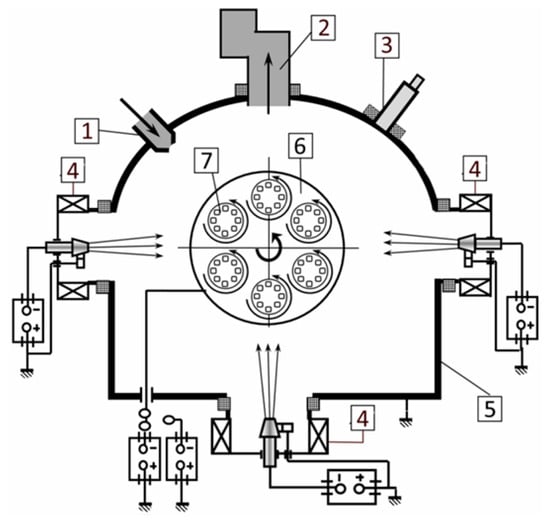
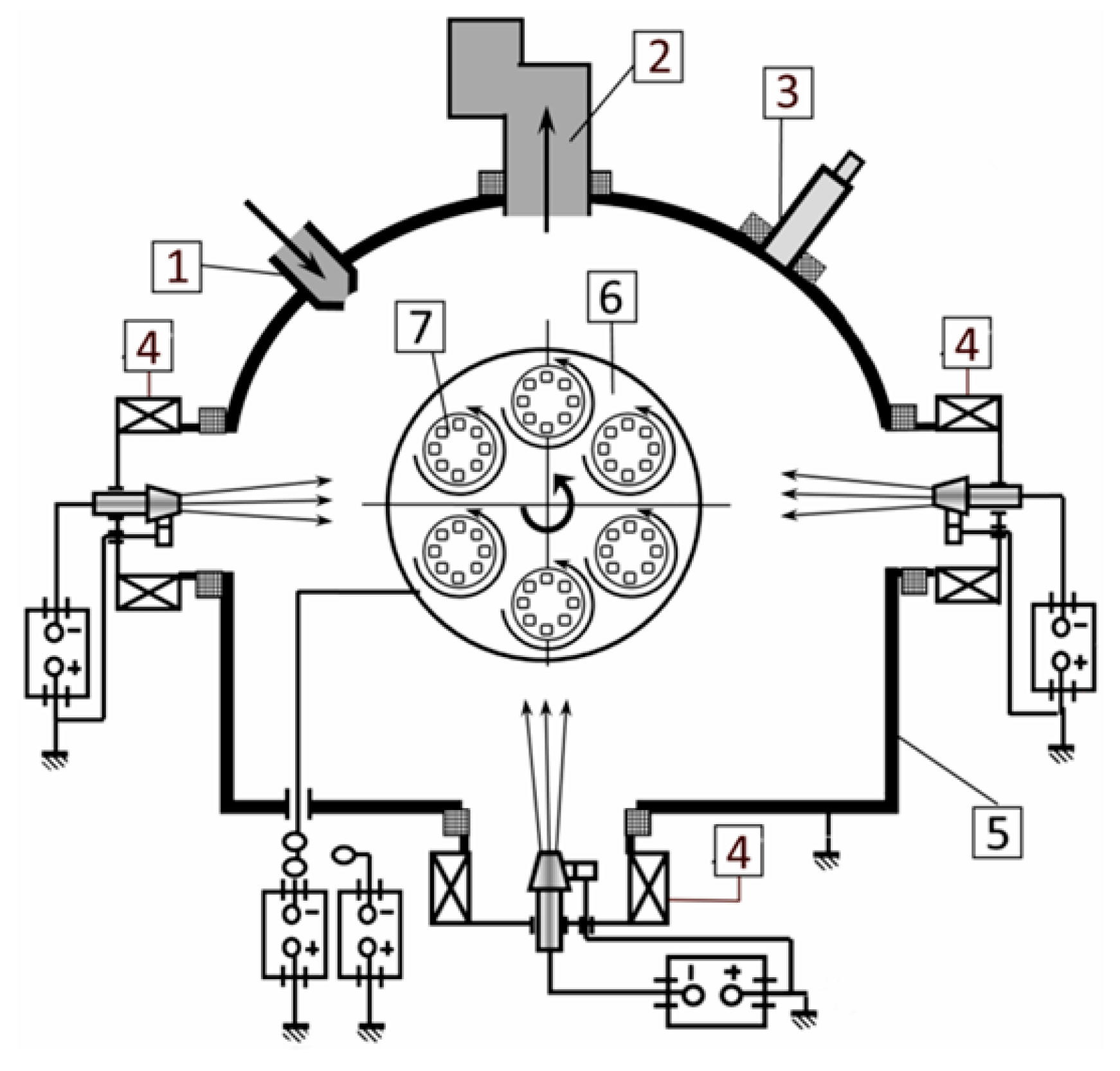
The coatings studied in the experiment were deposited using the VIT-2 experimental research installation (IDTI RAS-MSTU STANKIN, Moscow, Russia), and Figure 1 shows a schematic diagram of this equipment [38]. Two types of evaporators were installed: one is a filtered cathodic vacuum arc deposition (FCVAD) system, which allows for an up to 98% phase separation of microparticles and can provide a highly focused plasma flow. In addition, two controlled accelerated arc (CAA-PVD) system evaporators were also installed, which are characterized by high energy efficiency and can reduce the number of microparticles. The Al cathode (99.5% Al + 0.4% Si) was installed on the FCVAD evaporator, and through a magnetic-field-filtering device, the formation of Al droplets can be effectively reduced. The Zr-Hf cathode (50% Zr + 50% Hf) was installed on the evaporator of the CAA-PVD system.
Figure 1.
A schematic diagram of the VIT-2 installation for coating deposition. 1—gas leak; 2—vacuum system; 3—pyrometer; 4—CAA-PVD system evaporators; 5—vacuum chamber; 6—rotary table; 7—planetary rotating equipment [38].
The coatings were deposited on 7050-T7451 aluminum alloy substrates (diameter 28 mm × 3 mm). To enhance the adhesion between the coating and the substrate, the substrates were not subjected to grinding and polishing treatments prior to deposition. The samples were ultrasonically cleaned in acetone and absolute ethanol at 80 °C for 15 min each to remove surface oil and impurities, and dried in purified hot air. After loading the samples into the vacuum chamber, the system was pumped down to a base vacuum of 5.0 × 10⁻³ Pa.
In situ plasma etching (glow cleaning) was performed before deposition to thoroughly remove natural surface oxides and activate the substrates, thereby maximizing coating adhesion. During this process, 100 sccm of pure argon gas was introduced to maintain a pressure of 5.0 Pa, and the substrates were subjected to high-energy Ar+ bombardment at a bias voltage of −1200 V for 10 min.
An Al bond layer (deposition time: 5 min) and a (Zr,Hf,Al)N corrosion-resistant layer (deposition time: 45 min) were subsequently deposited. The deposition temperature was maintained between 300 °C and 350 °C, and the target-to-substrate distance was kept constant at 150 mm. The working gas was N2 (flow rate 150 sccm), and the deposition working pressure was precisely controlled at 0.42 Pa. This pressure ensured sufficient nitrogen reactants to form stoichiometric nitrides, while avoiding excessive plasma energy dissipation. A constant negative bias voltage of −150 V was applied to accelerate ions toward the substrate, providing sufficient atomic surface migration energy to promote coating densification and grain refinement without causing intense back-sputtering. The Al target current was maintained at 160 A to provide a stable Al ion flux, and the specific values of the process parameters were selected based on previous literature [37].
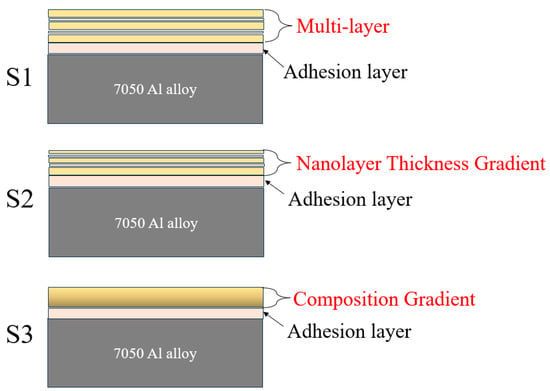
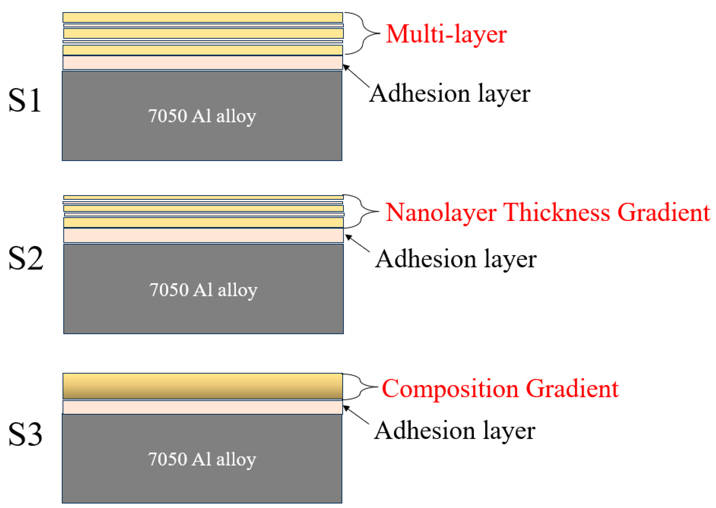
The nanolayered structure of the coatings was formed due to the planetary rotation of the substrate rotary table. Three groups of Al-(Zr,Hf,Al)N coatings were prepared, denoted as S1, S2, and S3, with their schematic structural diagrams shown in Figure 2. For the multilayer structure (S1), the cathodic arc current of the Zr-Hf target was kept constant at 85 A, and the sample turntable rotated at a constant speed of 0.7 rpm. For the nanolayer thickness gradient structure (S2), the Zr-Hf target current was also kept constant at 85 A, but during the deposition of the (Zr,Hf,Al)N layer, the initial rotation speed of the samples was set to 0.5 rpm and linearly increased at a gradual rate of approximately 0.044 rpm/min, reaching 2.5 rpm at the end of deposition. This controlled rotational acceleration led to a gradual decrease in the nanolayer thickness along the growth direction. Finally, for the compositional-gradient structure (S3), the initial cathodic arc current of the Zr-Hf target was set to 90 A and linearly decreased at a gradual rate of approximately 0.89 A/min, reaching 50 A at the end of the deposition. Crucially, it must be explicitly stated that no substrate rotation (0 rpm) was applied during the deposition of the S3 coating. This precisely controlled attenuation of the target evaporation rate and ion flux achieved a smooth transition and gradient evolution of the (Zr,Hf)/Al element ratio within the coating.
Figure 2.
Schematic diagrams of the structures of the three groups of samples.
2.2. Characterizations and Tests
The surface and cross-sectional morphologies and elemental distributions of the Al-(Zr,Hf,Al)N nano-multilayer coatings with different structures were characterized using a scanning electron microscope (SEM, EVO18, Carl Zeiss Microscopy GmbH, Jena, Germany) and an energy-dispersive spectrometer (EDS, X-Max20, Oxford Instruments, Abingdon, UK). The surface roughness of the coatings was measured by atomic force microscopy (AFM, NX7, Park Systems Corp., Suwon, Republic of Korea) operating in contact mode over a scanning area of 10 × 10 μm2. To reveal the microstructure of the (Zr,Hf,Al)N coating and the interfacial evolution between the coating and the 7050 Al substrate, samples were prepared by focused ion beam (FIB, Helios 5 CX, Thermo Fisher Scientific Inc., Waltham, MA, USA) and subsequently examined by transmission electron microscopy (TEM, JEM-F200, JEOL Ltd., Tokyo, Japan).
The electrochemical corrosion behaviors of the coatings were evaluated in a 3.5 wt.% NaCl solution. This specific concentration is universally utilized to simulate a typical harsh marine environment, elucidating its direct correlation with the industrial application conditions of aerospace and marine aluminum alloy components. A standard three-electrode cell was employed using a CHI660E electrochemical workstation (CH Instruments, Inc., Austin, TX, USA). A platinum plate served as the counter-electrode, and a saturated calomel electrode (SCE) was used as the reference electrode. Prior to testing, the non-working areas of the samples were strictly masked with epoxy resin, exposing an exact surface area of 1 cm2 to the electrolyte. All electrochemical measurements were conducted in naturally aerated solutions maintained at a constant ambient temperature of 25 ± 1 °C. The electrochemical measurements, including 30 min of open-circuit potential (OCP) monitoring, electrochemical impedance spectroscopy (EIS), and subsequent potentiodynamic polarization (PDP) tests, were conducted sequentially on the exact same specimen. After OCP testing, EIS tests were performed using an excitation signal with a frequency range from 100 kHz to 0.01 Hz. The AC amplitude was 10 mV. PDP tests were conducted at a scan rate of 0.001 V/s, with a potential range from −1600 mV to 0 mV.
Three sets of parallel experiments were conducted for both the PDP and EIS tests, and representative duplicate curves were adopted for analysis to ensure the absolute reproducibility and repeatability of the experimentations. All quantitative values and dimensions discussed throughout this manuscript are accompanied by their error ranges (±standard deviation). The corrosion morphologies were obtained by SEM after the potentiodynamic polarization tests, following ultrasonic cleaning of the briefly air-exposed samples in deionized water for 3 min.
3. Results
3.1. Surface and Cross-Sectional Morphology of the Coatings
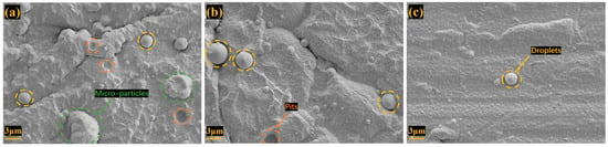
Figure 3 displays the surface morphologies of the Al-(Zr,Hf,Al)N coatings with three different structures. S1 and S2 exhibit non-smooth surface morphologies, and a greater number of microparticles are distributed on the surface of S1. In contrast, the surface of S3 is extremely smooth. The surface morphology of PVD coatings is strongly influenced by the deposition process, the target properties, and the initial surface state of the substrate [39]. Due to its flat surface, S3 exhibits the most obvious scratch-like features, which are presumed to originate from the initial surface state of the substrate prior to deposition. The presence of more microparticles observed on the surface of S1 is attributed to the instability of the cathodic arc and the irregular movement of the arc spots. The microparticles are generated through the collision, agglomeration, and growth of the (Zr,Hf,Al)N-containing plasma on the substrate surface. The enhancement of the mutual collision effect of the plasma leads to an increase in the conversion of the internal charges of the particles from negative to positive; therefore, the particles are more likely to be attracted to the substrate under a negative bias [40,41]. During the deposition process, weakly attached microparticles may be detached under high-energy particle bombardment, leading to the formation of pits, which are observed in S1. All three groups of samples exhibit typical fine-grained surface structural features, indicating the characteristics of columnar grain growth [42,43]. Due to lattice mismatch, columnar grain boundaries may develop into defects such as pinholes during the coating growth process, thereby reducing the corrosion resistance.
Figure 3.
The surface morphologies of the Al-(Zr,Hf,Al)N coatings: (a) S1; (b) S2; and (c) S3.
The primary factors for the fewer apparent defects in S3 are shallow ion implantation and ion sputtering during the deposition process. Due to the shallow ion implantation, growth occurs in the sub-surface layer of the coating, and the surface formed by this mechanism can effectively reduce apparent defects. The decrease in the ion sputtering rate can ensure that more ions are available to fill or smooth the protrusions and dents formed during the deposition process [44]. During the deposition of the near-surface layer of S3, the extremely small cathodic arc current of the Zr-Hf alloy target at this stage reduces the ion energy, leading to a decrease in the sputtering rate.
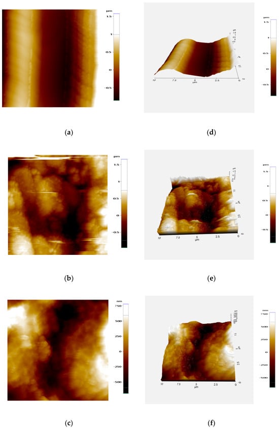
As shown in Figure 4, the surface roughness (Ra) of the three groups of samples was quantitatively measured by AFM. The relatively high Ra values of the three groups of samples are related to the unpolished substrate surface. The measurement results present a high degree of consistency with the surface morphologies. The multilayer structure significantly increases the surface Ra of the coating. A rough surface morphology caused by the agglomeration of microparticles was observed in both the S1 and S2 samples, with their Ra values being 0.444 ± 0.021 and 0.301 ± 0.015 μm, respectively, while the S3 sample exhibited the minimum roughness (0.250 ± 0.012 μm).
Figure 4.
AFM images showing the surface morphology and corresponding roughness of coatings: S1 (a,d); S2 (b,e); S3 (c,f).
The higher surface roughness of the nano-multilayer structure compared to the single-layer structure mainly originates from interlayer lattice mismatch. Due to the difference in lattice constants between the nanolayers, coherent strain energy is generated at the nanolayer interfaces. To release this continuously accumulating strain energy, the growth front of the coating undergoes morphological instability. It spontaneously evolves from smooth two-dimensional layer growth to rough three-dimensional island growth. In contrast, the single-layer coating maintains a relatively flat growth front due to its constant lattice parameters [45].
Furthermore, there was no substrate rotational motion during the deposition of the S3 sample, enabling the plasma flux to continuously bombard the substrate. Conversely, the substrate rotational motion during the deposition of the S1 and S2 samples caused the incident angle of the plasma flux bombarding the coating surface to fluctuate periodically. Obliquely incident high-energy ions will be blocked by the initial micro-protrusions on the coating surface, causing the protrusions to adsorb more ions and accelerate the coating growth rate, while the growth rate in the shadowed areas decreases due to being obstructed. This kinetic factor is speculated to be a major cause of the differences in coating surface roughness.
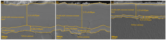
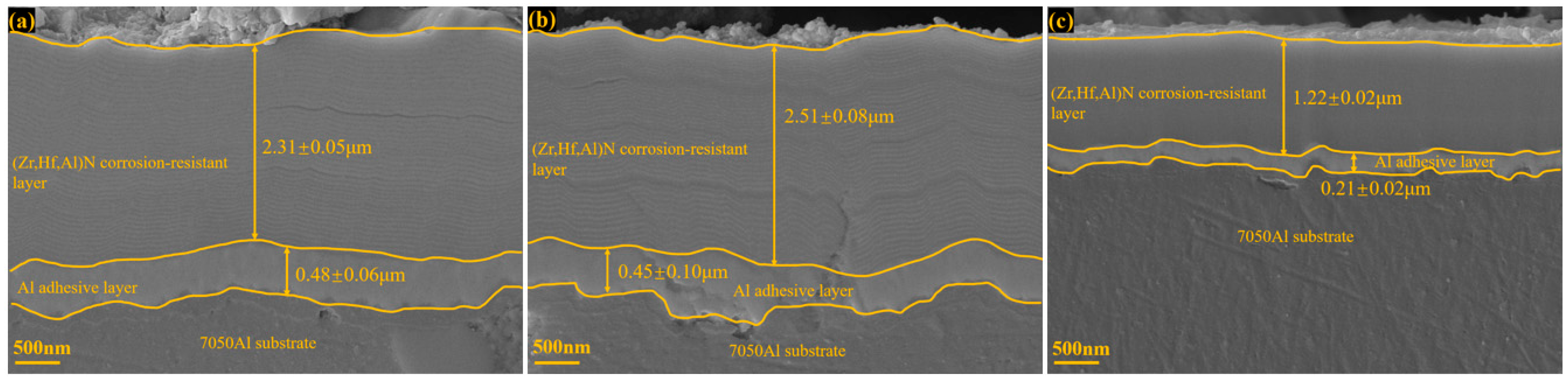
As shown in Figure 5, in terms of cross-sectional morphology, all three groups of samples exhibit a uniform and dense microstructure across the entire thickness range, with no obvious defects such as cracks or large inclusions, clearly displaying the bottom Al adhesion layer and the top (Zr,Hf,Al)N corrosion-resistant layer. However, the grain growth mode of the corrosion-resistant layer presents significant structural differences due to the different deposition strategies. Under a constant target current and a constant rotation speed, S1 formed a nano-multilayer structure with a constant modulation period. For S2, the linear variation in the sample turntable rotation speed manifests as a gradual decrease in the nanolayer thickness along the growth direction on its cross-section. The specific variations in the modulation period are shown in the transmission electron microscopy (TEM) characterization results below. The increase in the number of nanolayer interfaces led to an increase in the number of lattice distortion regions, resulting in a slight increase in the (Zr,Hf,Al)N layer thickness of S2 relative to S1, while the nanolayer interfaces can prevent the propagation of corrosion microcracks, which is beneficial for preventing the cracking and spallation of the coating [16]. S3 exhibits a dense and continuous morphology, without the clear nanolayer interfaces present in S1 and S2. At the same time, the significant reduction in the coating thickness of S3 reveals the positive correlation effect of the target cathodic arc current on the plasma flux and deposition rate. Due to the multilayer structure, S1 and S2 show nanolayer delamination phenomena in localized regions.
Figure 5.
The cross-sectional morphologies of the Al-(Zr,Hf,Al)N coatings: (a) S1; (b) S2; and (c) S3.
3.2. TEM Characterization Results
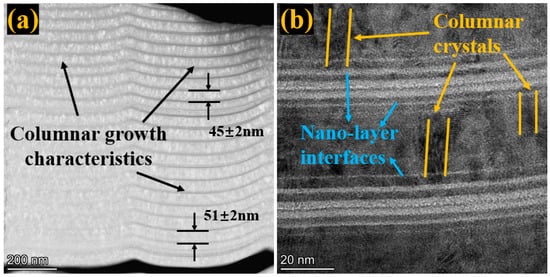
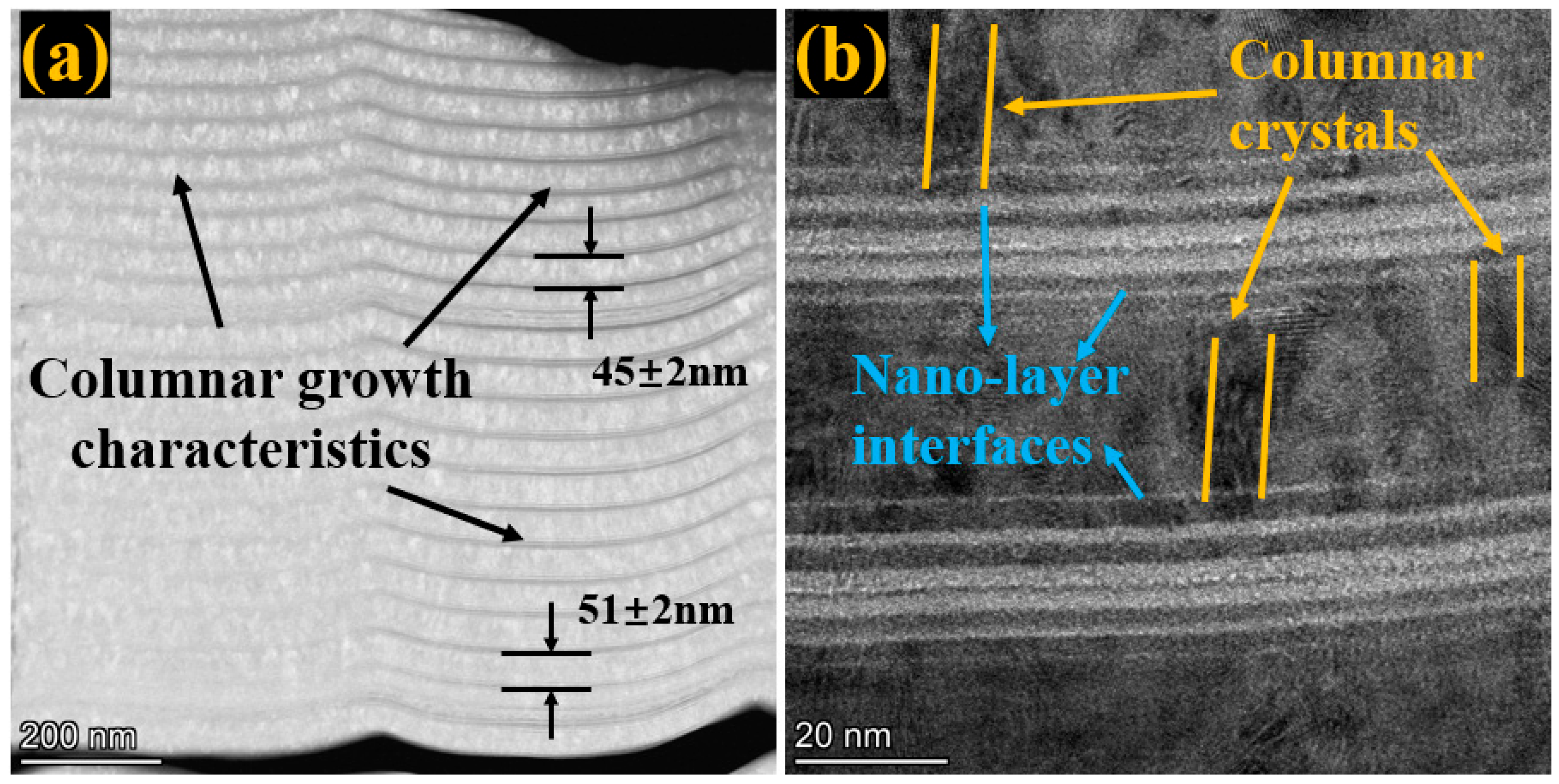
Figure 6 presents the transmission electron microscopy (TEM) analysis of S2. As shown in the low-magnification TEM cross-sectional image in Figure 6a, the coating exhibits a dense structure, and its thickness distribution presents inconsistency. The modulation periods were measured in two regions at different distances from the substrate; the modulation period in the lower region is 51 ± 2 nm, and the modulation period in the upper region is 45 ± 2 nm, confirming the formation of the nanolayer thickness gradient. The overall coating has no obvious defects, and distinct columnar grain growth characteristics can be observed within the nanolayers.
Figure 6.
TEM characterization of S2: (a) low-resolution overall morphology; (b) high-resolution local morphology.
Figure 6b displays a higher-resolution local nanolayer morphology, where nanosublayers inside the nanolayers are observed. Columnar grains blocked by nanolayer interfaces were observed in the coating, proving that the multilayer structure can effectively suppress the formation of penetrating columnar grains. Meanwhile, it can be reasonably considered that, compared to S1, the upper region of S2 has a higher density of nanolayer interfaces, which can further hinder the formation of columnar grain boundaries and pinhole defects, having a more effective diffusion-inhibiting effect on corrosive media.
3.3. Electrochemical Impedance Spectroscopy Test Results
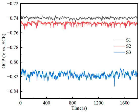
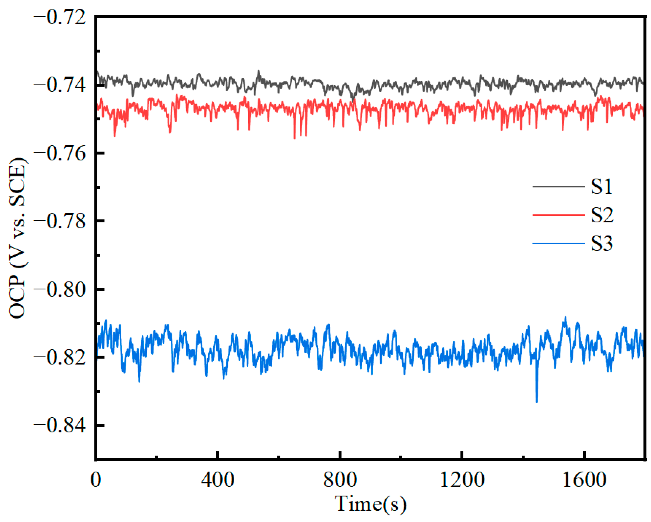
Prior to the EIS measurements, the open-circuit potential (OCP) of the coatings was continuously monitored for 1800 s in the 3.5 wt.% NaCl solution to evaluate the initial thermodynamic stability of the coating–substrate systems. As shown in Figure 7, the S1 and S2 coatings exhibited relatively noble and highly stable OCP values plateauing at approximately −0.74 V and −0.75 V (vs. SCE), respectively, indicating the establishment of a steady-state surface and excellent barrier protection. Conversely, the OCP of the S3 coating shifted significantly in the negative direction to approximately −0.82 V (vs. SCE). This notable negative shift indicates the rapid penetration of the electrolyte through structural defects, exposing the electrochemically active Al bond layer or 7050 Al substrate. More importantly, unlike the smooth curves of S1 and S2, the OCP of S3 exhibited continuous, high-frequency dynamic fluctuations (oscillations) throughout the entire monitoring period. These severe potential transients directly reflect the occurrence of intense active micro-galvanic corrosion and the dynamic detachment of hydrogen bubbles, confirming that the S3 electrode surface was in a highly non-stationary state.
Figure 7.
Open-circuit potential test curves for three sets of samples.
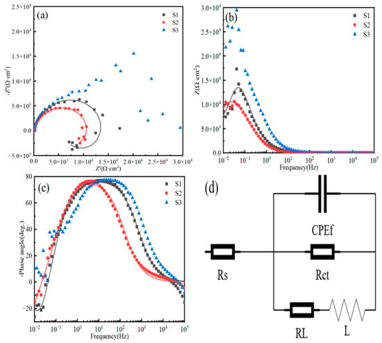
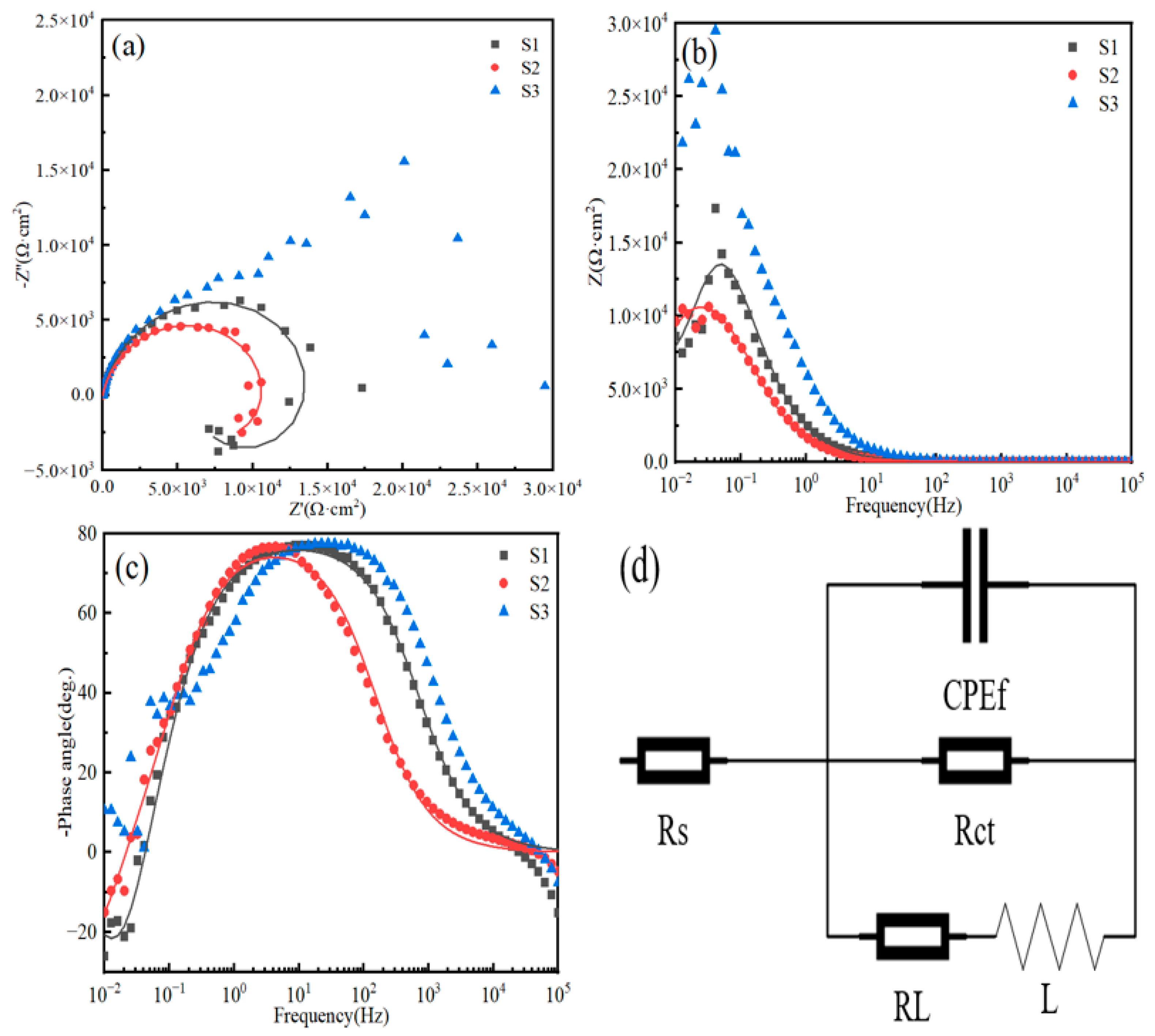
Following the OCP monitoring, EIS tests were conducted, as shown in Figure 8a–c. In these plots, the discrete points represent the experimental data, while the solid lines denote the corresponding simulated results fitted using the equivalent circuits shown in Figure 8d. The highly scattered impedance signals of S3 in the low-frequency region are the direct consequence of its severe non-stationary state, which was fully corroborated by the dynamically fluctuating OCP behavior discussed above. The rapid penetration of the electrolyte triggers intense micro-galvanic corrosion and rapid hydrogen bubble evolution, causing continuous dynamic disturbances at the solid–liquid interface. This inherently violates the linear time-invariant condition required for valid EIS measurements, manifesting as irreproducibly scattered impedance data. This phenomenon was consistently observed across all three independent S3 replicates, verifying its early-stage catastrophic failure.
Figure 8.
EIS test results for the Al-(Zr,Hf,Al)N coatings: (a) Nyquist plot; (b) Bode plot of impedance magnitude; (c) Bode plot of phase angle; (d) fitted circuit diagram.
S1 and S2 exhibit a complete capacitive semicircle and an incomplete inductive semicircle across the entire frequency range. The shape and radius of the semicircle related to the charge transfer resistance (Rct) are usually used to characterize the corrosion resistance. Generally, a larger radius of the capacitive arc implies a larger Rct and a lower corrosion rate, which is an important indicator for evaluating excellent corrosion resistance [46]. Obviously, S1 exhibits a higher impedance value.
The Bode plots shown in Figure 8b,c display the relationship of the impedance modulus |Z| and the phase angle θ with logarithmic frequency. The high-frequency region in the Bode plots represents the contact characteristics between the solution interface and the coating, the mid-frequency region is related to the corrosion situation inside the coating, and the low-frequency region indicates the contact characteristics between the coating and the substrate [47]. The impedance value |Z| corresponding to the lowest frequency (10−2 Hz) is used to characterize the potential of the electrochemical reaction in the electrolyte. The higher this value, the better the protective effect of the coating against further corrosion [48]. As shown in Figure 8b, S2 presents a higher low-frequency impedance(|Z|0.01 Hz) value relative to S1, indicating that S2 exhibits relatively better corrosion resistance at the interface between the coating and the substrate. Usually, a dense coating with fewer defects will exhibit a higher phase angle value; therefore, a larger maximum phase angle and a broader peak in the mid-frequency region also indicate better anti-corrosion performance [21]. The maximum phase angle values of the three groups of samples are close, all approximately 77°, but S1 possesses a broader peak in the mid-frequency range, indicating relatively better corrosion resistance of the coating. In addition, it can be found that the phase angle plots of S1 and S2 in the low-frequency region do not exhibit a “plateau” feature. On the contrary, when the applied frequency is less than 1 Hz, the phase angle drops sharply, indicating that a complete passive film is not formed on the coating surface in the NaCl solution.
To ensure the reliability of the EIS analysis and strictly validate the proposed equivalent circuits for the S1 and S2 samples, we conducted a statistical evaluation of the fitting quality. The attained experimented impedance data are compared with simulated results by using a complex non-linear least squares (CNLS) simulation [49,50]. For this purpose, the chi-squared (χ2) values are obtained and excellent fitting quality between the experimental and simulated values is achieved.
To assure the fundamental validity of the EIS data for S1 and S2, Kramers–Kronig (K-K) consistency transformations were performed prior to equivalent circuit modeling. The K-K tests yielded pseudo-χ2 values of less than 10−4 for both S1 and S2, with relative residuals for impedance modulus and phase angle randomly distributed within a narrow band of ±3%, confirming that the system satisfied the causality, linearity, and stability prerequisites. Subsequently, the proposed equivalent circuits (Figure 8d) were applied. The goodness-of-fit (χ2) of the S1 and S2 models was optimized to approximately 4.8 × 10⁻⁴ and 3.2 × 10⁻⁴, respectively. The solid lines plotted in the Nyquist and Bode plots represent these optimal fitted curves, perfectly matching the experimental data.
Considering that fitting an equivalent circuit to non-stationary |Z|0.01 Hz data violates the validity conditions of the K-K transforms, making the fitted circuit elements lack validity, and that performing equivalent circuit fitting for a rapidly failed coating has no practical significance, the equivalent circuit diagrams were only fitted for S1 and S2, utilizing the scattered EIS characteristics of S3 as a qualitative indicator of its rapid failure. Figure 8d displays the simulated equivalent circuit models for S1 and S2, and the EIS fitting parameters are shown in Table 1.
Table 1.
EIS parameters of S1 and S2 samples in 3.5 wt.% NaCl solution.
The confidence intervals of all extracted independent parameters were also strictly evaluated; the relative errors of the high-frequency and mid-frequency elements Rs and CPEf were consistently lower than 4%, while the errors of Rct, RL, and L were also well controlled, all within 10%. These statistical indicators confirm that the equivalent circuits closely reflect the electrochemical behavior of S1 and S2, with almost no systematic deviation.
In the fitted circuit diagrams, Rs represents the solution resistance between the working electrode and the reference electrode, and its value depends only on the conductivity of the test medium, which is negligible compared to other resistances [51]. Rct corresponds to the charge transfer resistance [52], and CPE represents the constant phase element. The impedance of CPE can be defined by the following formula [53]:
Here, n is introduced as an empirical exponent to explain the deviation from ideal capacitive behavior due to surface inhomogeneity, roughness factors, and adsorption effects, with its value ranging between 0 and 1. A larger value of n indicates that the behavior of the CPE is similar to that of a capacitor, while a lower value of n indicates that the coating has a rougher surface [54]. CPEf is related to the corroded area of the electrode, and a smaller value of CPEf implies a smaller electroactive surface area [55], which mutually verifies a higher Rct. RL is the pitting corrosion with inductance, and L represents the breakdown of the partial protective film on the surface of the alloy substrate [56]. The inductance L and resistance RL are connected in series in the circuit, indicating coating rupture. In summary, S2 exhibits better corrosion performance in the low-frequency range, while S1 exhibits better corrosion performance in the mid-frequency range.
ZCPE = 1/Y0(jω)n
3.4. Potentiodynamic Polarization Test Results
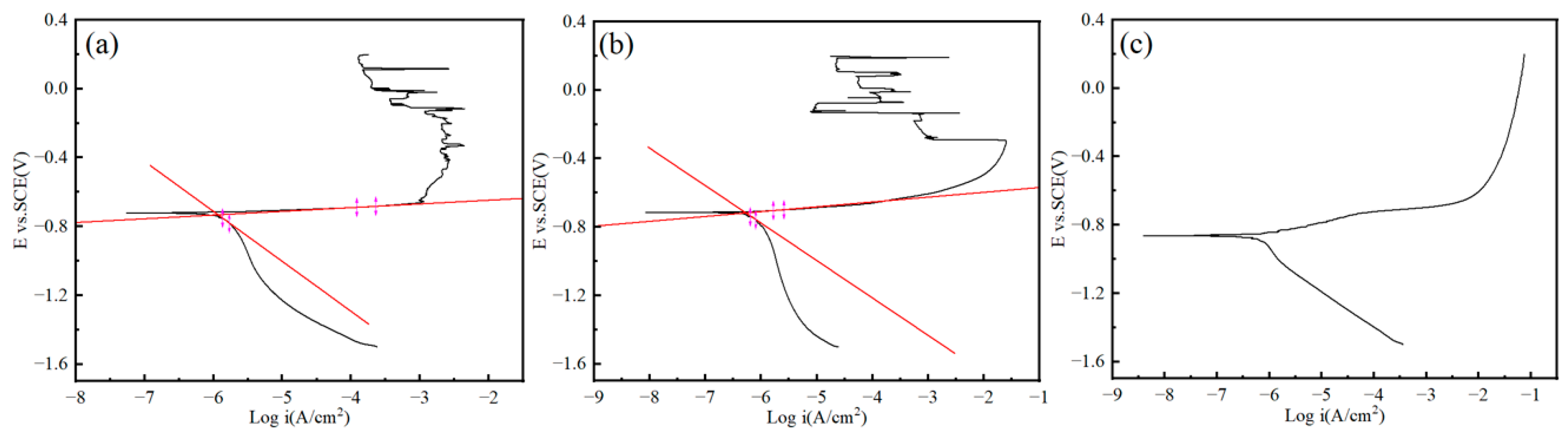
To analyze the corrosion process more comprehensively, particularly to analyze the reasons for the scattered low-frequency signals of S3, potentiodynamic polarization (PDP) tests were performed on the coatings. Figure 9 displays the polarization curves of the three groups of samples. In these curves, the anodic region represents the dissolution of the Al substrate, while the cathodic region represents the hydrogen evolution reaction (HER) and oxygen reduction reaction (ORR), with the reaction rates increasing as the current increases. The segment of the cathodic region close to the corrosion potential represents the ORR. The figure shows that the ORR of S1 and S2 is located between −0.7 V and −1.1 V, and the slope of the curve is relatively flat, indicating that the multilayer structure hindered the diffusion of corrosive media, which in turn hindered the diffusion of dissolved O in the corrosive media. As the potential continued to shift negatively, the HER acquired sufficient chemical driving force. The figure shows that the boundary of the linear regions between the HER segment and the ORR segment in the cathodic region is relatively distinct, indicating that the reaction rates of the HER and ORR are relatively stable, and the corrosion rate is uniform [57].
Figure 9.
Dynamic potential polarization curve of the Al-(Zr,Hf,Al)N coatings: (a) S1; (b) S2; and (c) S3.
The corresponding electrochemical parameters obtained from the anodic and cathodic polarization curves are summarized in Table 2. Generally, the absolute value of the corrosion potential (Ecorr) and the corrosion current density (icorr) are proportional to the corrosion rate measured by the polarization tests; that is, a smaller icorr and a higher Ecorr indicate better corrosion resistance of the coating [8,16]. To ensure the rigorous determination of icorr, the actual fitting intervals for Tafel extrapolation are explicitly depicted in the polarization plots in Figure 9a,b. The boundaries of the fitting intervals are marked by magenta lines, and the extrapolated linear regions are represented by solid red lines.
Table 2.
Fitting data of PDP curves of S1 and S2 samples in 3.5 wt.% NaCl solution.
The identification of these suitable Tafel regions required careful distinction from non-ideal electrochemical behaviors. For the cathodic branch, the extrapolation strictly avoided the deep negative potential range (where the slope flattens) to eliminate the interference of diffusion-controlled oxygen reduction. For the anodic branch, a clear distinction was made between the near-Ecorr activation region and the unstable response at more positive potentials. The severe, highly reproducible current serrations observed in S1 and S2 at higher anodic potentials indicate a dynamic breakdown of the passive film or localized flake spallation. Therefore, the anodic fitting intervals were strictly terminated prior to the onset of these transients to adhere to the steady-state assumption of Tafel kinetics. The statistical goodness-of-fit (R2) for these linear regions was evaluated and is appended to Table 2, confirming highly reliable extrapolation for S1 and S2 (R2 > 0.98).
Additionally, a distinct primary passivation current density (ipp) is clearly characterized for all examined samples in the anodic branch, indicating the initial formation of corrosion product films. However, as the potential further shifts anodically, both the S1 and S2 samples exhibit a pronounced trend toward “quasi-transpassivation”. This behavior is characterized by a gradual escalation in current density, suggesting localized breakdown or dynamic transpassive dissolution of the top layer. In sharp contrast, this quasi-transpassivation is entirely absent in S3; instead, it rapidly enters a state of active dissolution, further confirming its structural failure.
It is crucial to note that the anodic branches of S1 and S2 exhibit severe and continuous serrated fluctuations (current transients) when the potential exceeds approximately −0.4 V. Rather than instrumental noise, these highly reproducible fluctuations are interpreted as the in situ dynamic electrochemical response of the coating undergoing localized breakdown or shallow spallation. It is hypothesized that the localized release of high stress at the nanolayer interfaces leads to the momentary detachment of the coating flakes, exposing the underlying surface and causing a sharp increase in current. This is immediately followed by current drops due to temporary physical shielding by corrosion products. Due to the severe dynamic localized spallation observed in S1 and S2 during anodic polarization, their corrosion behavior significantly deviates from the uniform corrosion model. Consequently, the Stern–Geary equation is strictly inapplicable here, and the traditional polarization resistance (Rp) cannot be calculated, as the system is no longer under an activation-controlled steady state.
Previous electrochemical tests conducted by our group on the bare 7050 aluminum alloy substrate under identical conditions yielded an icorr of 3.474 × 10⁻⁵ A·cm−2 and an Ecorr of −1.187 V [25]. Compared to the substrate, S1 and S2 possess higher Ecorr and lower icorr, indicating that the multilayer (Zr,Hf,Al)N coatings effectively protected the substrate. The icorr of S2 is lower than that of S1, indicating that S2 exhibited better corrosion performance in the PDP tests.
In contrast, the S3 curve presents obvious non-Tafel characteristics because its electrochemical mechanism has deviated from the activation-controlled model, resulting in the absence of a Tafel linear region on the curve that can be used for linear extrapolation. This is primarily due to the existence of through-thickness columnar grain boundaries or pinhole defects within S3, which causes the electrolyte to directly penetrate the coating and make contact with the active aluminum alloy substrate or the Al adhesion layer. From the perspective of the cathodic branch, unlike S1 and S2, which possess a relatively flat diffusion-controlled ORR region, the cathodic branch of S3 is extremely steep and exhibits a continuous bending shape. This is because the direct exposure of the substrate triggered severe micro-galvanic corrosion and HER, and the generation and desorption of massive bubbles caused intense interfacial disturbance. Meanwhile, the Ecorr of S3 shifted significantly negatively, proving that the signal measured at this point was no longer the corrosion resistance behavior of the coating itself, but rather the characteristic potential of the active dissolution of the bottom adhesion layer or the Al substrate. In the early stage of anodic polarization, the dissolution of the Al adhesion layer or the substrate at the bottom of the defects might generate corrosion product precipitation. The products blocked the pores and reduced the active reaction area. Under this physical shielding effect, the anodic current could not increase linearly according to the exponential law of activation control, causing the anodic curve to bend sharply toward the upper right. The PDP test results further proved the phenomenon of the scattered low-frequency signals in the EIS tests, that is, the coating had already undergone severe corrosion failure in the early stage.
3.5. Electrochemical Corrosion Morphology of the Coatings
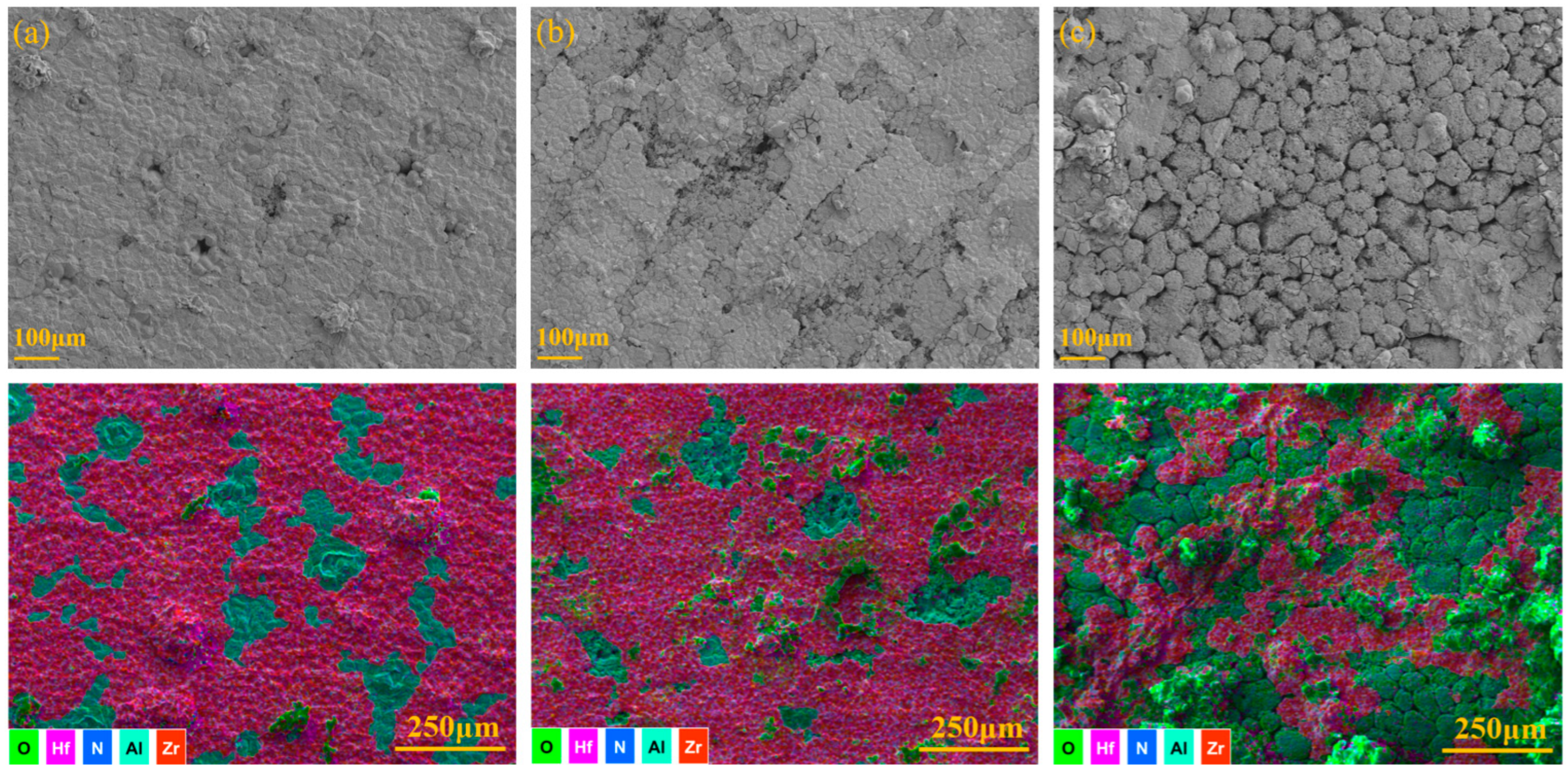
As shown in Figure 10, after the sequential electrochemical tests (OCP, EIS, and PDP), the surface morphologies and elemental distributions of the Al-(Zr,Hf,Al)N coatings visually reveal the ultimate corrosion damage. It must be explicitly noted that the necessary post-polarization ultrasonic cleaning step inevitably removed loosely adhered corrosion products and structurally compromised coating flakes. Consequently, the SEM images document the cumulative damage after the entire testing sequence and cleaning process, which likely exaggerates the visual extent of the spallation damage compared to the coating’s physical state during the earlier EIS measurements.
Figure 10.
Electrochemical corrosion morphology and elemental distribution of the Al-(Zr,Hf,Al)N coatings: (a) S1; (b) S2; and (c) S3.
For S1 and S2, the coating structures exhibit better integrity. The EDS elemental mapping results show that pitting corrosion dominates the corrosion behavior of S1 and S2. The relatively large number of surface microparticles serve as preferential adsorption sites for Cl− and O2 molecules, which then penetrate inward through pinhole defects. It can be observed that S1 formed a greater number of penetrating holes, while S2 exhibited significant flake-like spallation of the surface layer. This phenomenon may be related to the microstructure and elemental diffusion at the nanolayer interfaces. Furthermore, although the dense nanolayer interfaces in S1 and S2 effectively block the vertical penetration of the electrolyte, the lattice mismatch between the alternating sublayers inevitably generates localized micro-stresses. Supported by the relevant literature [58,59], it is proposed as a mechanistic hypothesis that this micro-regional residual stress, combined with the dynamic hydrogen evolution during polarization, weakens the localized interfacial adhesion. Consequently, this proposed mechanism leads to the observed shallow flake-like spallation rather than deep pitting. Future quantitative investigations focusing on the interfacial adhesion and macroscopic residual stress will be conducted to further validate these micro-mechanical behaviors.
In contrast, S3 suffered significant corrosion failure, and widely distributed large holes were observed. The columnar grain boundaries evolved into pinholes during the coating growth process, which developed into the large holes shown in the figure after erosion by the corrosive media. The EDS elemental mapping shows large areas of continuous Al and O signals, proving the exposure of the Al adhesion layer or Al substrate, and also indicating the generation of oxygen-rich corrosion products on the surface, which confirms that S3 suffered severe failure in the early stage of corrosion.
4. Discussion
This study evaluated the corrosion resistance of the three samples through EIS and PDP tests, respectively. Indisputably, S3 possesses the poorest corrosion resistance. However, regarding the performance comparison between S1 and S2, discrepancies exist in the results obtained from the different tests. S1 exhibits a larger capacitive arc radius in the Nyquist plot, simultaneously possessing a higher Rct, and shows a broader peak in the mid-frequency range in the Bode phase angle plot. In contrast, S2 exhibits a higher |Z|0.01 Hz value in the Bode impedance modulus plot, and shows a lower icorr in the early stage of the PDP test. Despite these seemingly contradictory conclusions, upon investigating the corrosion failure modes of the coatings, a high degree of consistency between them can be found.
Through the characterization of the corrosion morphologies, it can be concluded that the failure mode of S1 is pitting failure induced by discrete penetrating holes. Because its surface possesses the most widely distributed microparticle defects, and the surface layer lacks high-density nanolayer interfaces, the corrosive Cl− and O2 molecules extremely easily erode the surface defects and diffuse toward the substrate along the pinhole defects that developed from grain boundaries and phase boundaries. Therefore, S1 is prone to forming deeper corrosion paths, causing corrosion failure at the substrate interface, resulting in poor low-frequency electrochemical performance. However, because the coating structure is relatively well maintained, its high-frequency electrochemical performance is better, and it simultaneously has a relatively higher Rct. The failure mode of S2 is shallow spallation failure in the surface layer. Because the upper region of the S2 coating possesses more nanolayer interfaces, which hindered the continuous growth of columnar grains along the deposition direction during the coating deposition process, thereby hindering the diffusion of corrosive media to the substrate, its low-frequency electrochemical performance is better. However, the lattice distortion behavior at the nanolayer interfaces results in high stress in the upper region of the coating. During the erosion by corrosive media, microcracks easily initiate at the defects and shallow spallation failure occurs, reducing the structural integrity of the coating; thus, its high-frequency electrochemical performance is poor. Due to the fewer internal penetrating pinhole defects in S2, the amount of electron transfer at its exposed electrode is lower, resulting in a lower initial icorr.
From the microstructural characterization and corrosion performance test results, it is known that due to the lack of nanolayer interfaces, the coating structure of S3 had already failed in the early stage of the electrochemical tests. In the EIS tests, it manifested as scattered electrochemical signals. In the PDP tests, it manifested as a significant shift in electrochemical signals, which is attributed to the mixed signals of the corrosion behaviors of the coating and the substrate obtained due to the large-area exposure of the substrate. Considering the Nyquist plot of the examined sample S3, it is evident that a porous electrode behavior is characterized at a frequency domain between 10−1 and 10−2 Hz. This seems to characterize a porous electrode behavior associated with a trend toward inductor behavior in the lowest frequency domain range. A straight line forming an approximately 45-degree angle is constructed at this specified frequency range. Figure 4 and Figure 9 corroborate this trend toward porous electrode behavior. Thus, this distinctly suggests that the corrosion behavior of the examined S3 sample is provided by both planar and porous electrode behavior [60]. Consequently, a Warburg element was introduced in its equivalent circuit to simulate the diffusion processes through these pores.
However, as can be seen from the SEM results, the coating thickness might also be an important factor affecting the corrosion resistance of the coating. The decrease in the cathodic arc current caused a sharp reduction in the Zr and Hf ion fluxes. Coupled with the filtering and sputtering effects of Al ions, this sharply reduced the coating growth rate in the later deposition stage, ultimately resulting in a significantly lower thickness for S3 compared to S1 and S2. The decrease in thickness inevitably shortened the diffusion paths of the corrosive media. Therefore, in this case, the influence of thickness on corrosion resistance cannot be ruled out, and it would be necessary to increase the thickness of S3 to achieve the aim of controlling variables. However, an excessively high cathodic arc current will cause an increase in the surface defect density, aggravating the tendencies toward grain coarsening and elemental segregation. Conversely, an excessively low cathodic arc current will increase arc instability, reducing the structural continuity of the coating [61]. Broadening the gradient variation range of the cathodic arc current for the sake of controlling variables would further deteriorate the corrosion resistance of the coating. Therefore, in addition to the micro-defects analyzed previously, the poor corrosion resistance of S3 is also related to the important factor of thickness. In summary, the strategy of preparing compositional-gradient-structured coatings by regulating the cathodic arc current will inevitably produce the unfavorable factor of reduced coating thickness, which needs to be considered in practical engineering applications.
It must be emphasized that the PDP and EIS tests in this study primarily reflect the short-term electrochemical response and initial corrosion behavior of the coatings [62]. The blocking effect of the coating structure on the diffusion paths of the corrosive media is particularly evident during this initial stage. However, due to the lack of long-term immersion, cyclic corrosion, or salt spray test data, this study did not evaluate the long-term service life of the coatings. Long-term tests still need to be carried out in the future to further verify the long-term protective performance of these multilayer and gradient structures in complex marine environments.
The limitations of this paper and future research directions also need to be pointed out. First, because the corrosion resistance of S3 is extremely poor, this paper focused on the multilayer coatings and did not conduct a fine characterization of the microstructure of S3. In fact, carefully studying the microstructure of S3 to explore the essential reasons for the extremely poor corrosion resistance of the compositional-gradient-structured coating is equally important. F. C. da Silva et al. [63] conducted a more in-depth analysis of gradient structures through TEM, XPS, and grazing incidence XRD, which could provide an important reference basis for future research. On the other hand, the deposition temperature of 300–350 °C in this experiment is relatively high for the 7050 aluminum alloy, which might cause the growth of precipitated phases in the substrate and the degradation of its mechanical properties. Furthermore, this study did not involve quantitative residual stress and adhesion force tests on the coatings. Consequently, this study solely discusses the influence of structural design on the intrinsic electrochemical corrosion performance of the coatings. In future research, evaluations of the mechanical and tribological properties of both the substrate and the coatings should be conducted to ensure that this deposition process does not damage the structure of the light alloy substrate, and to systematically clarify the correlations among mechanical properties, tribological properties, and corrosion performance.
5. Conclusions
In this study, Al-(Zr,Hf,Al)N composite coatings with three different architectures (constant multilayer S1, nanolayer thickness gradient S2, and compositional gradient S3) were successfully deposited on 7050 aluminum alloy using the FCVAD technique. By systematically correlating the microstructural evolution with the electrochemical responses in a 3.5 wt.% NaCl solution, the following primary conclusions can be drawn:
- (1)
- Microstructural Tailoring via Deposition Strategy: The dynamic regulation of the substrate turntable rotation and target arc current significantly altered the coating architecture and thickness. S1 exhibited a constant nanolayer thickness, while the linearly increased rotation speed for S2 successfully induced a nanolayer thickness gradient. In S3, the stationary substrate turntable resulted in the formation of a single-layer structure without nanolayer interfaces, and the continuous current attenuation led to a significant reduction in the overall coating thickness.
- (2)
- Deposition-Strategy-Induced Variations in Corrosion Resistance: S1 and S2 exhibited similar corrosion performance, with their corrosion potentials significantly higher than that of the S3 coating. The corrosion resistance of the multilayer structure was vastly superior to that of the single-layer coating, whereas the nanolayer thickness gradient structure showed an insignificant enhancement effect on corrosion resistance. The dense interfaces in the upper region are interpreted to effectively block the continuous growth of columnar grains, thereby dynamically inhibiting the vertical penetration of corrosive media. However, the localized micro-stress at these interfaces is hypothesized to trigger shallow flake-like spallation under high anodic polarization. The compositional-gradient deposition strategy in S3 caused early-stage failure of the coating, primarily due to the dual factors of lacking nanolayer interfaces and a thinner coating thickness. These factors allowed the almost through-thickness columnar grain boundaries and pinhole defects to act as channels for rapid electrolyte penetration.
- (3)
- Failure Mechanisms of Multilayer Coatings: Although S1 demonstrated excellent high-frequency impedance, its relatively fewer nanolayer interfaces failed to completely block the propagation of discrete penetrating pinholes, leading to localized pitting failure at the substrate interface. In contrast, the increased interfacial density in the upper region of S2 effectively interrupted columnar grain growth and hindered vertical electrolyte diffusion, yielding the lowest corrosion current density and the highest |Z|0.01 Hz. However, the accumulated lattice distortion and stress at the dense nanolayer interfaces induced shallow flake-like spallation under corrosive erosion.
- (4)
- Engineering Implications: This study elucidates that utilizing a multilayer structural design to increase the nanolayer interfacial density is a highly effective strategy for enhancing the short-term intrinsic corrosion resistance of protective coatings. However, future in-depth evaluations of long-term service stability (e.g., via prolonged immersion or salt spray tests) and corresponding mechanical properties (e.g., adhesion and residual stress) are essential to comprehensively validate the practical applicability of multilayer structures in harsh marine environments.
Author Contributions
Conceptualization, data curation, writing—original draft, Y.W. and T.H.; methodology, resources, writing—review and editing, A.V.; investigation, writing—review and editing, X.D., A.O. and M.N.; supervision, project administration, funding acquisition, T.H. All authors have read and agreed to the published version of the manuscript.
Funding
This research was funded by the National Natural Science Foundation of China (Grant No. 52275350) and the International Cooperation Research Platform Construction Project of Shanghai University of Engineering Science (Grant No. 0301006).
Institutional Review Board Statement
Not applicable.
Informed Consent Statement
Not applicable.
Data Availability Statement
Data are contained within the article.
Conflicts of Interest
The authors declare no conflicts of interest.
References
- Dursun, T.; Soutis, C. Recent developments in advanced aircraft aluminium alloys. Mater. Des. (1980–2015) 2014, 56, 862–871. [Google Scholar] [CrossRef] [Scilit]
- Tisza, M.; Czinege, I. Comparative study of the application of steels and aluminium in lightweight production of automotive parts. Int. J. Lightweight Mater. Manuf. 2018, 1, 229–238. [Google Scholar] [CrossRef] [Scilit]
- Wen, L.; Wang, Y.; Zhou, Y.; Ouyang, J.-H.; Guo, L.; Jia, D. Corrosion evaluation of microarc oxidation coatings formed on 2024 aluminium alloy. Corros. Sci. 2010, 52, 2687–2696. [Google Scholar] [CrossRef] [Scilit]
- Wang, R.-Q.; Wu, Y.-K.; Wu, G.-R.; Chen, D.; He, D.-L.; Li, D.; Guo, C.; Zhou, Y.; Shen, D.; Nash, P. An investigation about the evolution of microstructure and composition difference between two interfaces of plasma electrolytic oxidation coatings on Al. J. Alloys Compd. 2018, 753, 272–281. [Google Scholar] [CrossRef] [Scilit]
- Miller, W.; Zhuang, L.; Bottema, J.; Wittebrood, A.J.; De Smet, P.; Haszler, A.; Vieregge, A. Recent development in aluminium alloys for the automotive industry. Mater. Sci. Eng. A 2000, 280, 37–49. [Google Scholar] [CrossRef] [Scilit]
- Chen, Q.; Jiang, Z.; Tang, S.; Dong, W.; Tong, Q.; Li, W. Influence of graphene particles on the micro-arc oxidation behaviors of 6063 aluminum alloy and the coating properties. Appl. Surf. Sci. 2017, 423, 939–950. [Google Scholar] [CrossRef] [Scilit]
- Li, J.; He, T.; Du, X.-Y.; Vereschaka, A. Enhancing the corrosion resistance of high-strength Al-Zn-Mg-Cu alloys after equal channel angular pressing by developing retrogression and re-aging strategies. Corros. Sci. 2025, 246, 112736. [Google Scholar] [CrossRef] [Scilit]
- Wang, Y.; He, T.; Du, X.; Okulov, A.; Vereschaka, A.; Li, J.; Ding, Y.; Chen, K.; He, P. Aging-Induced Microstructural Transformations and Performance Enhancement of Cr/DLC Coatings on ECAP-7075 Aluminum Alloy. Coatings 2025, 15, 1017. [Google Scholar] [CrossRef] [Scilit]
- Huang, Q.; Liu, L.; Wu, Z.; Ji, S.; Wu, H.; Chen, P.; Ma, Z.; Wu, Z.; Fu, R.K.; Lin, H. Corrosion-resistant plasma electrolytic oxidation coating modified by Zinc phosphate and self-healing mechanism in the salt-spray environment. Surf. Coat. Technol. 2020, 384, 125321. [Google Scholar] [CrossRef] [Scilit]
- Chen, L.; Liu, Z.; Shen, Q. Enhancing tribological performance by anodizing micro-textured surfaces with nano-MoS2 coatings prepared on aluminum-silicon alloys. Tribol. Int. 2018, 122, 84–95. [Google Scholar] [CrossRef] [Scilit]
- Wang, J.; Huang, S.; He, M.; Wangyang, P.; Lu, Y.; Huang, H.; Xu, L. Microstructural characteristic, outward-inward growth behavior and formation mechanism of MAO ceramic coating on the surface of ADC12 Al alloy with micro-groove. Ceram. Int. 2018, 44, 7656–7662. [Google Scholar] [CrossRef] [Scilit]
- Wang, Y.; Liu, X.-B.; Liu, Y.-F.; Luo, Y.-S.; Meng, Y. Microstructure and tribological performance of Ni60-based composite coatings on Ti6Al4V alloy with different Ti3SiC2 ceramic additions by laser cladding. Ceram. Int. 2020, 46, 28996–29010. [Google Scholar] [CrossRef] [Scilit]
- Chen, L.; Guo, Z.; Zhang, C.; Wu, C.; Li, Y.; Jia, Y.; Liu, G. Effects of Ni coating thickness on the microstructure and mechanical properties of resistance-welded WC-Co/B318 steel joints. Ceram. Int. 2021, 47, 25634–25644. [Google Scholar] [CrossRef] [Scilit]
- Deng, H.; Chen, D.; Wang, Y.; Zhou, Y.; Gao, P. Effects of silicon on microstructure and corrosion resistance of diamond-like-carbon film prepared on 2024 aluminum alloy by plasma-enhanced chemical vapor deposition. Diam. Relat. Mater. 2020, 110, 108144. [Google Scholar] [CrossRef] [Scilit]
- Liu, W.; Chu, Q.; Zeng, J.; He, R.; Wu, H.; Wu, Z.; Wu, S. PVD-CrAlN and TiAlN coated Si3N4 ceramic cutting tools—1. Microstructure, turning performance and wear mechanism. Ceram. Int. 2017, 43, 8999–9004. [Google Scholar] [CrossRef] [Scilit]
- Ding, Y.; He, T.; Xiangyang, D.; Vereschaka, A.; Sotova, C.; Li, J.; Wang, Y.; He, P. Influence of nitrogen pressure on microstructure, mechanical, and tribocorrosion properties of (Zr, Cr, Al) N coatings on aluminum alloy. Tribol. Int. 2026, 218, 111720. [Google Scholar] [CrossRef] [Scilit]
- Vogli, E.; Tillmann, W.; Selvadurai-Lassl, U.; Fischer, G.; Herper, J. Influence of Ti/TiAlN-multilayer designs on their residual stresses and mechanical properties. Appl. Surf. Sci. 2011, 257, 8550–8557. [Google Scholar] [CrossRef] [Scilit]
- Liu, L.; Tang, W.; Zhou, L.; Wu, Z.; Ruan, Q.; Li, X.; Qasim, A.M.; Cui, S.; Li, T.; Fu, R.K. Comparative study of TiAlN coatings deposited by different high-ionization physical vapor deposition techniques. Ceram. Int. 2020, 46, 10814–10819. [Google Scholar] [CrossRef] [Scilit]
- Shugurov, A.R.; Kazachenok, M.S. Mechanical properties and tribological behavior of magnetron sputtered TiAlN/TiAl multilayer coatings. Surf. Coat. Technol. 2018, 353, 254–262. [Google Scholar] [CrossRef] [Scilit]
- Pac, M.J.; Pinot, Y.; Giljean, S.; Rousselot, C.; Delobelle, P.; Ulhaq-Bouillet, C.; Tuilier, M.H. Investigation of Ti0.54Al0.46/Ti0.54Al0.46 N multilayer films deposited by reactive gas pulsing process by nano-indentation and electron energy-loss spectroscopy. Thin Solid Films 2017, 634, 96–106. [Google Scholar] [CrossRef] [Scilit]
- Wang, L.; Wang, M.; Chen, H. Corrosion mechanism investigation of TiAlN/CrN superlattice coating by multi-arc ion plating in 3.5 wt% NaCl solution. Surf. Coat. Technol. 2020, 391, 125660. [Google Scholar] [CrossRef] [Scilit]
- Mani, S.P.; Agilan, P.; Kalaiarasan, M.; Ravichandran, K.; Rajendran, N.; Meng, Y. Effect of multilayer CrN/CrAlN coating on the corrosion and contact resistance behavior of 316L SS bipolar plate for high temperature proton exchange membrane fuel cell. J. Mater. Sci. Technol. 2022, 97, 134–146. [Google Scholar] [CrossRef] [Scilit]
- Zhou, Q.; Bai, X.; Chen, X.; Peng, D.; Ling, Y.; Wang, D. Corrosion resistance of duplex and gradient CrNx coated H13 steel. Appl. Surf. Sci. 2003, 211, 293–299. [Google Scholar] [CrossRef] [Scilit]
- Kameneva, A.; Kichigin, V. Corrosion, wear, and friction behavior of a number of multilayer two-, three-and multicomponent nitride coatings on different substrates, depending on the phase and elemental composition gradient. Appl. Surf. Sci. 2019, 489, 165–174. [Google Scholar] [CrossRef] [Scilit]
- Chen, K.; He, T.; Du, X.; Vereschaka, A.; Sotova, C.; Ding, Y.; Li, J. Corrosion Resistance of Ti/Cr Gradient Modulation Period Nanomultilayer Coatings Prepared by Magnetron Sputtering on 7050 Aluminum Alloy. Inorganics 2025, 13, 242. [Google Scholar] [CrossRef] [Scilit]
- Akhter, R.; Zhou, Z.; Xie, Z.; Munroe, P. TiN versus TiSiN coatings in indentation, scratch and wear setting. Appl. Surf. Sci. 2021, 563, 150356. [Google Scholar] [CrossRef] [Scilit]
- Wang, Q.; Lin, Y.; Zhou, F.; Kong, J. Electrochemical properties promotion of CrSiN coatings in seawater via Ni incorporation. J. Alloys Compd. 2021, 856, 157450. [Google Scholar] [CrossRef] [Scilit]
- Feng, C.; Zhu, S.; Li, M.; Xin, L.; Wang, F. The effect of Hf on the oxidation and corrosion behavior of Ti0.7Al0.3N coating prepared by arc-ion plating. Oxid. Met. 2009, 71, 63–76. [Google Scholar] [CrossRef] [Scilit]
- Jiang, C.; Qian, L.; Feng, M.; Liu, H.; Bao, Z.; Chen, M.; Zhu, S.; Wang, F. Benefits of Zr addition to oxidation resistance of a single-phase (Ni,Pt)Al coating at 1373 K. J. Mater. Sci. Technol. 2019, 35, 1334–1344. [Google Scholar] [CrossRef] [Scilit]
- Jiang, C.Y.; Yang, Y.F.; Zhang, Z.Y.; Bao, Z.B.; Chen, M.H.; Zhu, S.L.; Wang, F.H. A Zr-doped single-phase Pt-modified aluminide coating and the enhanced hot corrosion resistance. Corros. Sci. 2018, 133, 406–416. [Google Scholar] [CrossRef] [Scilit]
- Barshilia, H.C.; Selvakumar, N.; Deepthi, B.; Rajam, K. A comparative study of reactive direct current magnetron sputtered CrAlN and CrN coatings. Surf. Coat. Technol. 2006, 201, 2193–2201. [Google Scholar] [CrossRef] [Scilit]
- Aihua, L.; Jianxin, D.; Haibing, C.; Yangyang, C.; Jun, Z. Friction and wear properties of TiN, TiAlN, AlTiN and CrAlN PVD nitride coatings. Int. J. Refract. Met. Hard Mater. 2012, 31, 82–88. [Google Scholar] [CrossRef] [Scilit]
- Chen, W.; Lin, Y.; Zheng, J.; Zhang, S.; Liu, S.; Kwon, S.C. Preparation and characterization of CrAlN/TiAlSiN nano-multilayers by cathodic vacuum arc. Surf. Coat. Technol. 2015, 265, 205–211. [Google Scholar] [CrossRef] [Scilit]
- Anders, A. Approaches to rid cathodic arc plasmas of macro-and nanoparticles: A review. Surf. Coat. Technol. 1999, 120, 319–330. [Google Scholar] [CrossRef] [Scilit]
- He, C.; Zhang, J.; Wang, J.; Ma, G.; Zhao, D.; Cai, Q. Effect of structural defects on corrosion initiation of TiN nanocrystalline films. Appl. Surf. Sci. 2013, 276, 667–671. [Google Scholar] [CrossRef] [Scilit]
- Cedeño-Vente, M.L.; Manríquez, J.; Mondragón-Rodríguez, G.C.; Camacho, N.; Gómez-Ovalle, A.E.; Gonzalez-Carmona, J.M.; Alvarado-Orozco, J.M.; Espinosa-Arbelaez, D.G. Application of a transmission line model to evaluate the influence of structural defects on the corrosion behavior of arc-PVD CrN coatings. Ceram. Int. 2021, 47, 20885–20899. [Google Scholar] [CrossRef] [Scilit]
- Grigoriev, S.; Vereschaka, A.; Uglov, V.; Milovich, F.; Tabakov, V.; Cherenda, N.; Andreev, N.; Migranov, M. Influence of the tribological properties of the Zr, Hf-(Zr, Hf) N-(Zr, Me, Hf, Al) N coatings (where Me is Mo, Ti, or Cr) with a nanostructured wear-resistant layer on their wear pattern during turning of steel. Wear 2023, 518, 204624. [Google Scholar] [CrossRef] [Scilit]
- Grigoriev, S.; Volosova, M.; Bublikov, Y.; Sotova, C.; Milovich, F.; Seleznev, A.; Shmakov, I.; Vereschaka, A. A Study of the Features of Coating Deposition on a Carbide Substrate Using Preliminary Etching with Glow-Discharge Plasma. Surfaces 2024, 7, 920–937. [Google Scholar] [CrossRef] [Scilit]
- Ma, G.; Lin, G.; Sun, G.; Zhang, H.; Wu, H. Characteristics of DLC containing Ti and Zr films deposited by reactive magnetron sputtering. Phys. Procedia 2011, 18, 9–15. [Google Scholar] [CrossRef] [Scilit]
- Bilek, M.M.M.; Martin, P.J.; McKenzie, D.R. Influence of gas pressure and cathode composition on ion energy distributions in filtered cathodic vacuum arcs. J. Appl. Phys. 1998, 83, 2965–2970. [Google Scholar] [CrossRef] [Scilit]
- Cao, H.; Yang, J.; Li, Y.; Ren, L.; Qi, F.; Zhao, N.; Zhou, Y.; Li, B.; Ouyang, X. Effect of nitrogen pressure on the microstructure, mechanical and electrochemical properties of CrAlN coatings deposited by filter cathode vacuum arc. Ceram. Int. 2022, 48, 36570–36584. [Google Scholar] [CrossRef] [Scilit]
- Liu, L.; Ruan, Q.; Wu, Z.; Li, D.; Huang, C.; Wu, Y.; Li, T.; Wu, Z.; Tian, X.; Fu, R.K. Fabrication and cutting performance of CrAlN/CrAl multilayer coatings deposited by continuous high-power magnetron sputtering. Ceram. Int. 2022, 48, 14528–14536. [Google Scholar] [CrossRef] [Scilit]
- Cunha, L.; Andritschky, M.; Pischow, K.; Wang, Z. Microstructure of CrN coatings produced by PVD techniques. Thin Solid Films 1999, 355, 465–471. [Google Scholar] [CrossRef] [Scilit]
- Shu, C.; Ye, Y.; Yin, S.; Zhang, D.; Huang, S.; Cao, H. Microstructure, mechanical, tribological, and glass molding properties of ta-C coating on tungsten carbide molds via filtered cathodic vacuum arc technology. Ceram. Int. 2025, 51, 37144–37156. [Google Scholar] [CrossRef] [Scilit]
- Petrov, I.; Barna, P.; Hultman, L.; Greene, J. Microstructural evolution during film growth. J. Vac. Sci. Technol. A Vac. Surf. Films 2003, 21, S117–S128. [Google Scholar] [CrossRef] [Scilit]
- He, T.; Valery, Z.; Vereschaka, A.; Keshin, A.; Huo, Y.; Milovich, F.; Sotova, C.; Seleznev, A. Influence of niobium and hafnium doping on the wear and corrosion resistance of coatings based on ZrN. J. Mater. Res. Technol. 2023, 27, 6386–6399. [Google Scholar] [CrossRef] [Scilit]
- Jin, J.; He, Z.; Zhao, X. Effect of Al content on the corrosion resistance and conductivity of metal nitride coating in the cathode environment of PEMFCs. Mater. Chem. Phys. 2020, 245, 122739. [Google Scholar] [CrossRef] [Scilit]
- Wang, Y.; He, T.; Du, X.; Vereschaka, A.; Sotova, C.; Ding, Y.; Chen, K.; Li, J.; He, P. Influence of Aluminum Alloy Substrate Temperature on Microstructure and Corrosion Resistance of Cr/Ti Bilayer Coatings. Coatings 2025, 15, 891. [Google Scholar] [CrossRef] [Scilit]
- Meyer, Y.A.; Menezes, I.; Bonatti, R.S.; Bortolozo, A.D.; Osório, W.R. EIS investigation of the corrosion behavior of steel bars embedded into modified concretes with eggshell contents. Metals 2022, 12, 417. [Google Scholar] [CrossRef] [Scilit]
- Orazem, M.E.; Pébère, N.; Tribollet, B. Enhanced graphical representation of electrochemical impedance data. J. Electrochem. Soc. 2006, 153, B129–B136. [Google Scholar] [CrossRef] [Scilit]
- Hu, Z.; Yin, Z.; Yin, Z.; Wang, K.; Liu, Q.; Sun, P.; Yan, H.; Song, H.; Luo, C.; Guan, H. Corrosion behavior characterization of as extruded Mg-8Li-3Al alloy with minor alloying elements (Gd, Sn and Cu) by scanning Kelvin probe force microscopy. Corros. Sci. 2020, 176, 108923. [Google Scholar] [CrossRef] [Scilit]
- Ascencio, M.; Pekguleryuz, M.; Omanovic, S. Corrosion behaviour of polypyrrole-coated WE43 Mg alloy in a modified simulated body fluid solution. Corros. Sci. 2018, 133, 261–275. [Google Scholar] [CrossRef] [Scilit]
- Vengesa, Y.; Fattah-alhosseini, A.; Elmkhah, H.; Imantalab, O. Influence of post-deposition annealing temperature on morphological, mechanical and electrochemical properties of CrN/CrAlN multilayer coating deposited by cathodic arc evaporation-physical vapor deposition process. Surf. Coat. Technol. 2022, 432, 128090. [Google Scholar] [CrossRef] [Scilit]
- Shi, X.; Wang, Y.; Li, H.; Zhang, S.; Zhao, R.; Li, G.; Zhang, R.; Sheng, Y.; Cao, S.; Zhao, Y. Corrosion resistance and biocompatibility of calcium-containing coatings developed in near-neutral solutions containing phytic acid and phosphoric acid on AZ31B alloy. J. Alloys Compd. 2020, 823, 153721. [Google Scholar] [CrossRef] [Scilit]
- Wei, X.; Feng, H.; Liu, Z.; Chen, Z.; Yin, P.; Lu, S.; Ding, J.; Du, N.; Li, X.; Zhang, G. Insight into the corrosion behaviors and mechanism of the self-healing Si/N-DLC films in oilfield environment. Corros. Sci. 2024, 231, 111989. [Google Scholar] [CrossRef] [Scilit]
- Zhu, Y.; Gao, W.; Huang, H.; Chang, W.; Zhang, S.; Zhang, R.; Zhao, R.; Zhang, Y. Investigation of corrosion resistance and formation mechanism of calcium-containing coatings on AZ31B magnesium alloy. Appl. Surf. Sci. 2019, 487, 581–592. [Google Scholar] [CrossRef] [Scilit]
- Yin, S.; Duan, W.; Liu, W.; Wu, L.; Yu, J.; Zhao, Z.; Liu, M.; Wang, P.; Cui, J.; Zhang, Z. Influence of specific second phases on corrosion behaviors of Mg-Zn-Gd-Zr alloys. Corros. Sci. 2020, 166, 108419. [Google Scholar] [CrossRef] [Scilit]
- Yang, J.; Shou, D.; Zhao, N.; Tang, Y.; Cao, H.; Qi, F.; Ouyang, X. Interfacial structure, mechanical properties, and corrosion resistance of Cr/TiSiN nano-multilayer coating by filtered cathode vacuum arc technique. J. Manuf. Process. 2025, 136, 267–281. [Google Scholar] [CrossRef] [Scilit]
- Wang, Y.; He, T.; Du, X.; Vereschaka, A.; Okulov, A.; Sotova, C.; Ding, Y. Modulation of metal ion deposition behavior and evolution of wear and corrosion failure mechanisms in (Zr, Cr, Al) N nanolayered composite coatings via substrate bias voltage. Appl. Surf. Sci. 2026, 751, 168251. [Google Scholar] [CrossRef] [Scilit]
- Lasia, A. Modeling of impedance of porous electrodes. In Modeling and Numerical Simulations; Springer: New York, NY, USA, 2008; pp. 67–137. [Google Scholar]
- Grigoriev, S.; Vereschaka, A.; Milovich, F.; Sitnikov, N.; Seleznev, A.; Sotova, C.; Bublikov, J. Influence of the yttrium cathode arc current on the yttrium content in the (Ti, Y, Al) N coating and the coating properties. Vacuum 2024, 222, 113028. [Google Scholar] [CrossRef] [Scilit]
- Wang, X.; Guo, L.; Liu, X.; Dai, Y.; She, J.; Zhang, D.; Qi, F.; Wei, W.; Ouyang, X. Enhanced corrosion resistance and cell activity of magnesium alloy by DCPD/MgHPO4· 3H2O coating via one-step chemical conversion. Surf. Coat. Technol. 2024, 476, 130228. [Google Scholar] [CrossRef] [Scilit]
- da Silva, F.C.; Tunes, M.; Edmondson, P.D.; Lima, N.B.; Sagás, J.C.; Fontana, L.C.; Schön, C.G. Grid-assisted magnetron sputtering deposition of nitrogen graded TiN thin films. SN Appl. Sci. 2020, 2, 865. [Google Scholar] [CrossRef] [Scilit]

Disclaimer/Publisher’s Note: The statements, opinions and data contained in all publications are solely those of the individual author(s) and contributor(s) and not of MDPI and/or the editor(s). MDPI and/or the editor(s) disclaim responsibility for any injury to people or property resulting from any ideas, methods, instructions or products referred to in the content. |
© 2026 by the authors. Licensee MDPI, Basel, Switzerland. This article is an open access article distributed under the terms and conditions of the Creative Commons Attribution (CC BY) license.