


Abstract
Reactive power compensation (RPC) in ships is critical for the stability, efficiency, and safety of the electric power system. It ensures voltage stability, reduces generator and alternator load, and adapts to dynamic and variable loads. This study evaluates the ship’s electrical power system. The implementation of advanced compensation strategies across three distinct operational scenarios is intended to systematically mitigate reactive load demand, thereby contributing to the enhancement of overall power utilization efficiency and ensuring improved stability of the vessel’s energy management framework. Three real-life data sets (148, 120, and 102 min) were analyzed to extract reactive power variations. MATLAB R2023b is used to calculate and graph required compensation and capacitance, generated time-series responses, and produced comparative graphs, enabling evaluation of the most effective compensation strategy for a shipboard microgrid in diesel–electric supply vessel systems. The findings highlight the importance of advanced control algorithms, predictive management, and hybrid compensation topologies in achieving reliable and efficient reactive power management in ships. There were three distinct situations in which the goal power factor (PF) values of 0.90, 0.95, and 0.98 were analyzed. These values were determined under three load conditions. Within the context of operations, compensating just up to 0.90 resulted in savings of 6.26%; however, optimizing up to 0.98 resulted in an increase in savings to 13.91%, which is over double the amount.
1. Introduction
For a sustainable future, global warming requires immediate action. The Paris Agreement aims to achieve net-zero emissions by 2050 and a 45% decrease in CO2 emissions from 2010 levels by 2030. In keeping with these objectives, the International Maritime Organization (IMO) has established challenging climate goals for the shipping industry, which is a significant source of greenhouse gases (GHGs) worldwide [1,2]. The IMO wants to achieve a 5–10% adoption of zero-emission fuels and reduce CO2 emissions by 40% and total GHGs by at least 20% (preferably 30%) by 2030. The objective is to reduce GHG emissions by 70–80% by 2040 to reach net-zero by 2050 [3].
The maritime industry is currently navigating a period of unprecedented technological transformation, driven by the dual imperatives of environmental sustainability and operational efficiency. As the IMO tightens its grip on carbon intensity through frameworks such as the Energy Efficiency Existing Ship Index (EEXI) and the Carbon Intensity Indicator (CII), the electrification of vessel propulsion has moved from a niche innovation to a mainstream necessity [4,5]. Within this context, supply vessels represent a particularly complex challenge and opportunity for electrical engineering. These vessels operate in some of the most demanding marine environments, performing tasks that range from very low load conditions to high load conditions [6]. The shift toward diesel–electric hybrid propulsion allows for the decoupling of engine speed from propeller demand, offering significant fuel savings. However, this transition also introduces sophisticated power quality (PQ) issues, primarily centered on the management of reactive power and harmonic distortion caused by the widespread use of non-linear loads, such as variable frequency drives (VFDs) and high-power induction motors [7,8,9].
The demand for electrical energy is growing due to population growth and industrialization, requiring higher quality and reliability. PQ is crucial for the efficient use of electrical energy, encompassing voltage stability, frequency accuracy, and harmonic distortion. High PQ ensures optimal equipment performance, reduces energy losses, and minimizes downtime, while poor PQ results in elevated operating costs and potential equipment damage. In recent years, efforts to improve PQ have increased, focusing on ensuring a continuous energy supply, maintaining a PF close to 1, balancing phase voltages, and keeping total harmonic distortion (THD) within standard limits [10,11,12].
The energy efficiency of ship power systems depends on the effective and rational control of electrical energy. During the transmission and conversion of electrical energy into different forms, a reactive power exchange occurs between the inductive and capacitive elements of the system [13]. Enhancing reactive power can lead to increased system load ability and improved ship efficiency, manifested as a reduction in active power losses, which subsequently decreases fuel oil consumption and negative environmental impacts [14].
Reactive power is directly related to voltage stability, and insufficient reactive power leads to voltage instability and reduced system efficiency. It is generated by capacitors and generators and consumed by inductors. This power is essential for power factor correction (PFC) and the stable operation of power transmission lines. The main goal is to minimize reactive power flow and ensure the efficient utilization of transmission systems [15,16,17]. Under varying operating conditions, the voltage and frequency deviations in ship electrical power systems are higher than their nominal values, and this situation is particularly evident in ships with electric propulsion systems. The increase in the number and power of onboard loads, especially impulsive and fluctuating loads, leads to higher harmonic levels, voltage fluctuations, transient phenomena, three-phase imbalances, and higher reactive power, which negatively affect the stability of the ship’s electrical network [18,19].
The availability of diesel electric propulsion systems has provided numerous advantages to ship owners, including improved compliance with international regulations, more flexibility and reliability, decreased operational expenses, and enhanced access to innovative automation technologies [20]. However, owners also encounter highly dynamic and unpredictable fluctuations in propulsion load due to atmospheric conditions and operational modes, which decrease PQ [21,22]. High-power, non-linear propulsion loads, and power–electronic converters in supply vessel AC (alternating current) power systems can cause significant PQ problems. These include voltage and frequency instability, oscillations in active and reactive power, imbalanced loads, and increased harmonic currents. Such issues place additional stress on parallel generators, raise system losses, contribute to electromagnetic compatibility (EMC) challenges, and, under extreme transient events such as short circuits, sudden load changes, or pulsed operations, may even threaten overall system stability [23].
Early studies on power compensation in ship electrical systems initially focused on identifying PQ and reactive power problems arising from the isolated, low-inertia nature of shipboard microgrid (SMG) networks, particularly in diesel–electric and early all-electric ship concepts. They demonstrated that rapidly varying propulsion and auxiliary loads lead to voltage instability, elevated reactive power circulation, harmonic distortion, and increased losses, making compensation a system-level necessity rather than a local corrective measure. These studies established simulation-based analysis and PQ measurement as essential foundations for compensation design. As a solution, converter-based equipment, such as shunt active power filters, was introduced, showing that dynamic compensation could simultaneously mitigate reactive power demand and harmonics under pulsed and non-linear loading conditions, where passive capacitor banks were insufficient [4,18,19,24,25].
More recent studies have expanded to include economic and operational justification, linking poor PF to higher generator loading, fuel consumption, and emissions, and demonstrating that automatic PF compensation could deliver measurable efficiency and cost benefits. The literature increasingly framed ships as islanded microgrids, investigate advanced compensation methods—such as capacitor-based dynamic compensation, static synchronous compensator (STATCOM) and hybrid topologies, virtual impedance control, and deep reinforcement learning—to stabilize voltage, enhance reactive power sharing, and maintain system reliability during propulsion transients, pulsed loads, environmental fluctuations, and complex operational modes [19,23,26,27,28,29].
The latest studies address reactive power sharing among inverter-dominated sources, adaptive droop and virtual impedance control, and the integration of compensation strategies with energy management systems to meet IMO efficiency and emission targets. Collectively, this body of work converges on the view that modern shipboard power compensation must be dynamic, coordinated, data-driven, and economically optimized, forming a core element of resilient and energy-efficient maritime power systems [13,21,30,31,32].
However, regarding research on shipboard PQ and using dynamic and hybrid reactive power compensation (HRPC), the literature includes nonsystematic evaluations of advanced RPC strategies under multiple real-world operational scenarios for hybrid or diesel–electric supply vessels (DESVs).
This research examines how the efficiency of DESVs can be improved by implementing the HRPC strategy. As vessels become increasingly dependent on complex electronic propulsion systems and VFDs, they face the issue of low PF, which leads to wasted generator capacity and increased harmful emissions. This study does not evaluate instantaneous frequency and harmonic changes in voltage and current values.
A global PF analysis was conducted, focusing on the compensation that can be applied to the system and the utilization of generator capacity. To make the electrical capacity produced by generators more effective according to demand, it is recommended to combine static capacitor banks for fixed base loads with dynamic compensation, which provides fast, real-time adjustments to propulsion power demands that vary at specific intervals during operations. Using this dual-layer architecture, ships can recover more than 13% of their electrical capacity and significantly reduce fuel consumption, thereby ensuring grid stability and compliance with environmental standards.
2. Literature Review
The history of marine electrification began in the late 19th century with simple lighting systems, but the modern era is defined by the integrated power system (IPS), where a common electrical platform supports both propulsion and auxiliary loads [9,33]. In a DESV, the traditional mechanical link between the prime mover and the propeller is replaced by an electrical transmission line [7,14]. This architecture typically utilizes several medium-speed diesel generators (DGs) feeding a main AC switchboard, which then distributes power to propulsion drives, thrusters, and hotel loads [23,30]. The primary advantage is the ability to run the optimal number of generators at their most efficient load point, typically between 75% and 100% of their rated capacity [14,23,29].
Despite these benefits, the integration of high-power semiconductor-based drives introduces significant PQ disturbances. PQ on ships is generally characterized by voltage and frequency stability and the absence of harmonic distortion [8,10,34]. When induction motors are driven by VFDs, the rectification process draws current in non-sinusoidal pulses. This non-linearity creates harmonic currents that propagate through the SMG, causing voltage notches, increased electromagnetic interference (EMI), and significant thermal stress on electrical equipment [8,9,35]. Furthermore, the magnetizing current required by induction motors inherently lags the voltage, creating a demand for reactive power (Q) that does not contribute to propulsion but consumes the capacity of the generators [10,36].
The global maritime industry is currently undergoing a paradigm shift in energy management, driven by the dual imperatives of stringent environmental regulations and the pursuit of operational cost optimization. As vessels transition toward more integrated electrical propulsion systems, the complexity of SMG has increased significantly [4,5]. These systems, which are effectively isolated microgrids, must maintain high PQ under highly variable and often extreme operational conditions [6]. A critical challenge in this context is the management of reactive power and the mitigation of harmonic distortion, which are exacerbated by the proliferation of non-linear loads such as VFDs and high-capacity induction motors [7,8,9].
This research presents an exhaustive investigation into RPC strategies, specifically proposing HRPC architecture, which includes static and dynamic compensation for DESVs to optimize PF and enhance overall system efficiency.
Within this context, the DESV represents a particularly complex challenge and opportunity for electrical engineering in SMG. These vessels operate in some of the most demanding marine environments, performing tasks that range from high-speed transits to precise station-keeping via dynamic positioning (DP) systems [6]. The shift toward diesel–electric hybrid propulsion allows for the decoupling of engine speed from propeller demand, offering significant fuel savings. However, this transition also introduces sophisticated PQ issues, primarily centered on the management of reactive power and harmonic distortion caused by the widespread use of non-linear loads [7,9].
The fundamental efficiency of a ship’s electrical grid is governed by the PF, which dictates the relationship between the active power performing work and the apparent power that the DGs must provide. A low PF results in increased current flow for the same active power output, leading to thermal losses in cables, transformers, and alternators, necessitating the over-dimensioning of the vessel’s power plant [10,11,12].
In modern vessels, the presence of non-linear loads further complicates this relationship, as traditional displacement PF is supplemented by distortion PF, necessitating a more advanced approach to compensation [18,34,35].
In this study, the Fryze approach has been adopted for the calculations of apparent power, active power, and reactive power. This study explores the implementation of various RPC architectures—static, dynamic, and hybrid—specifically tailored for a DESV equipped with four generators and two asynchronous propulsion motors. By developing specific calculation methodologies for these architectures across diverse operational modes, it is demonstrated that a hybrid (static–dynamic) approach provides the optimal balance of speed, precision, and cost-effectiveness for maritime applications.
3. Materials and Methods
This section states that the primary engine of the tugboat operated for 148, 120, and 102 min at three distinct intervals. The calculated loads for the main engine were employed. It was anticipated that thrusters powered by asynchronous (induction) motors would be used to compensate for the traditional engine loads. To ensure that the diesel generator set (GenSet) can supply the system with the electrical energy that it requires, calculations and evaluations were carried out.
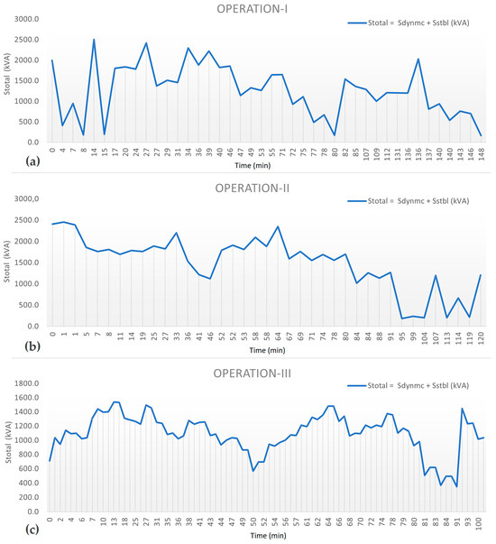
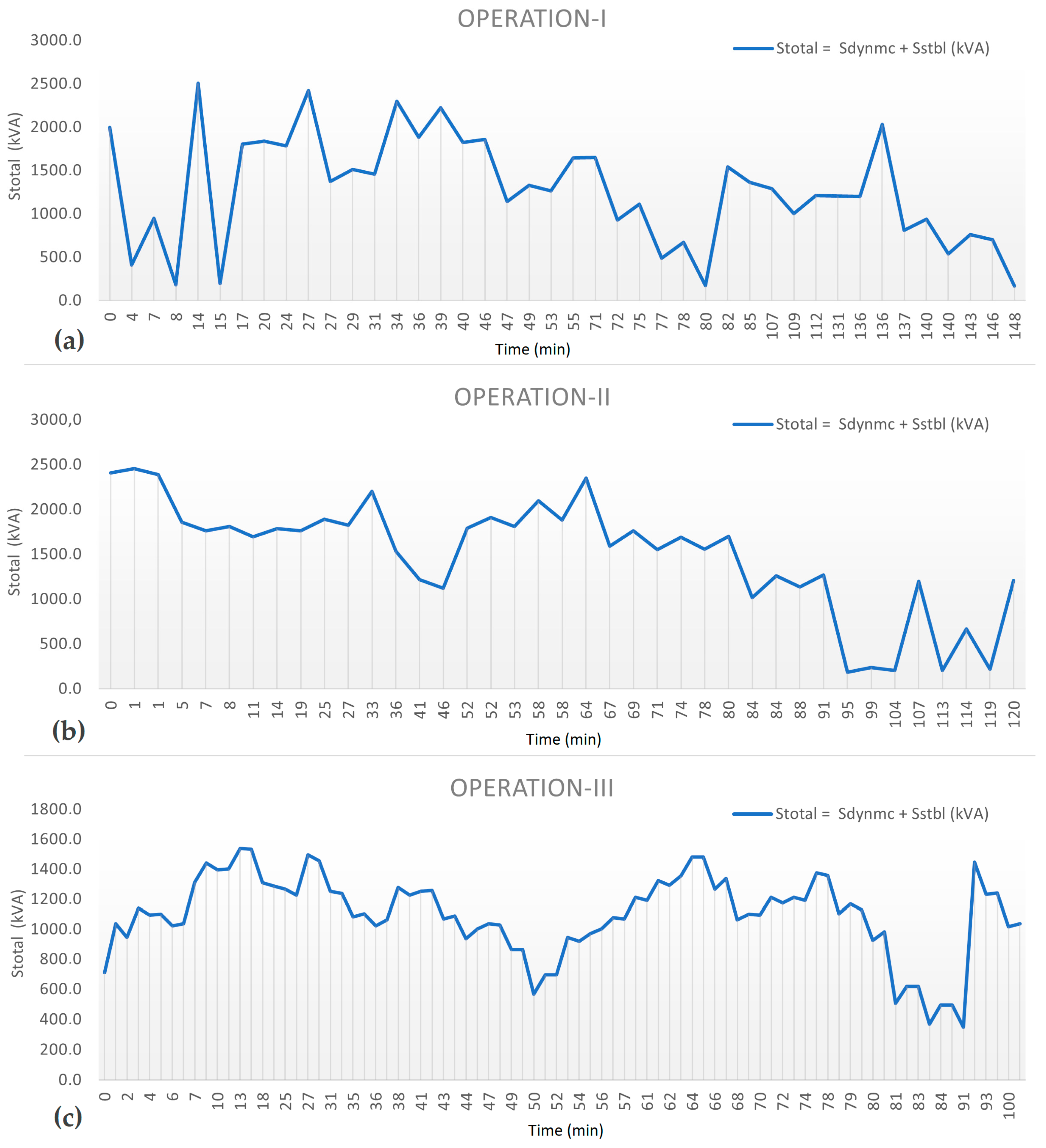
In Figure 1, 148, 120, and 102 min are the three operating values of the supply ship’s electrical loads, and the graph that follows contains an illustration of the load variation that occurred during those three time periods.
Figure 1.
Electrical load–time variation graphs for three operations of supply vessel: (a) Operation-I, (b) Operation-II, and (c) Operation-III.
Prior to the computation of the compensation values that are required by the system as a result of these load variations, the interrelationships between active power, reactive power, apparent power, and PF are explained through the utilization of formulas. The computations that are relevant to this matter are also determined. Within the scope of this evaluation, the Fryze method was utilized for the purpose of calculating apparent power, active power, and reactive power [37].
The assumption was made that the present operational data would draw power from the system at a consistent pace measured in minutes, and calculations were carried out in accordance with this assumption. While it was intended to be an overall assessment, voltage and current harmonics that could be caused by drive systems and instantaneous load changes were not taken into consideration.
3.1. Theoretical Foundations of Reactive Power and PF Correction
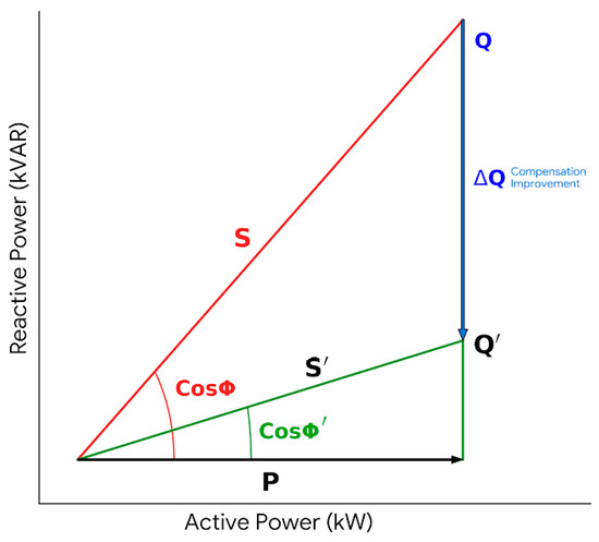
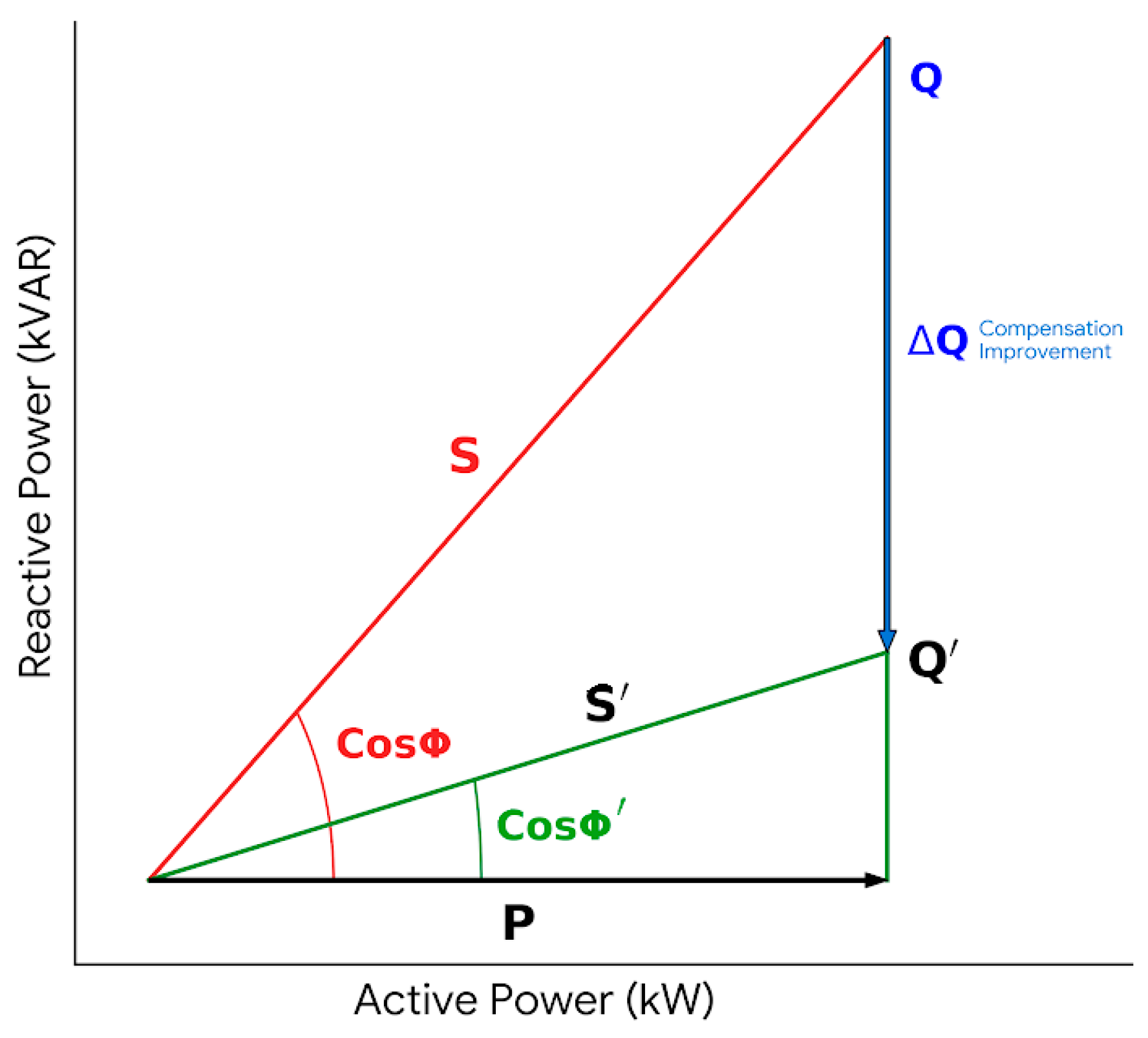
In a standard AC electrical system, the total power supplied, known as apparent power (S), is the vector sum of active power (P) and reactive power (Q). This relationship is visually represented by the power triangle in Figure 2, where the angle (Φ) between active and apparent power determines the PF [11,14,36].
Figure 2.
Power triangle: RPC improvement.
The PF is mathematically defined as:
PF = P/S
In a balanced three-phase marine system, the apparent power is calculated as:
where V is the line-to-line voltage and I is the line current. The relationship between the three components follows the Pythagorean theorem:
Improving the PF involves injecting “leading” reactive power into the system to counteract the “lagging” reactive power consumed by inductive loads. This reduces the total apparent power demand (S) and, consequently, the current (I) drawn from the generators [11,38,39]. The reduction in current leads to lower I2R copper losses in the distribution network and prevents the unnecessary heating of alternators [10,12].
To calculate the required compensation capacity (ΔQ) to move from an existing PF (Cos Φ) to a target PF′ (Cos Φ′), the following formula is utilized:
where:
ΔQ = P × (Tg Φ − Tg Φ′)
Φ = Arccos(Cos Φ)
Φ′ = Arccos(Cos Φ′)
3.2. Comparative Analysis of RPC Architectures
RPC on ships can be implemented through various architectures, each offering different levels of performance and complexity. These are generally classified into static, dynamic, and hybrid systems. In this subsection, RPC architectures are examined and a comparison table is provided in summary form in Table 1.
3.2.1. Static Compensation Systems
Static compensation typically employs fixed or switched capacitor banks. These systems are “static” because they do not utilize high-speed power electronics for continuous control, although they may use contactors or thyristors to switch capacitor steps in and out of the circuit [12,39,40].
In a marine context, static compensation is most effective for loads that are constantly in operation and have a stable reactive power demand, such as large fans, pumps, or the vessel’s hotel load [41,42]. Capacitor banks are relatively simple to install and maintain, and they provide a cost-effective way to improve the baseline PF of the vessel [12,39]. However, they suffer from several limitations. The response speed of contactor-switched banks is in the range of seconds, which is too slow to follow the rapid load changes of a propulsion motor during maneuvering [40,43,44]. Furthermore, fixed capacitors can create a risk of harmonic resonance if the system’s inductive reactance matches the capacitance at a harmonic frequency, potentially leading to over-voltages and equipment failure [40,45,46].
3.2.2. Dynamic Compensation Systems
Dynamic compensation technologies, such as static var generators (SVGs) or STATCOMs, represent a significant advancement in PQ management. These devices use voltage source converters (VSCs) based on insulated gate bipolar transistors (IGBTs) to generate or absorb reactive power in real-time [40,44].
Unlike capacitor banks, which are passive sources of reactive current, an SVG acts as an active current source. It can respond to changes in the grid within a few milliseconds, providing seamless and precise control of the PF. This speed is essential for mitigating the effects of voltage flickers and sags during the starting of large asynchronous motors or during sudden load changes in DP mode [43]. Beyond that, SVGs do not run the risk of harmonic resonance and can even be programmed to provide active harmonic filtering, canceling out the distortions produced by other non-linear loads on the ship [44,47]. The primary drawback of purely dynamic systems is their higher capital cost and the need for more sophisticated cooling and control infrastructure [41].
Table 1.
Comparative analysis of RPC architectures [5,48,49].
3.2.3. Hybrid Compensation Systems
The hybrid architecture combines the advantages of both static and dynamic systems. In this configuration, a set of static capacitor banks handles the majority of the steady-state reactive power demand, while a dynamic module provides the fine-tuning and transient response [38,41,44,46,48].
For a modern DESV, the hybrid approach is highly recommended. It allows for a more compact and cost-efficient design by reducing the required power rating of the expensive SVG component. The static part handles the “coarse” baseline compensation, while the dynamic part handles the “fine” rapidly changing components and mitigates harmonics. This collaborative approach ensures that the vessel maintains a near-unity PF across all operating conditions, from quiet harbor modes to intensive DP operations.
3.3. Detailed Calculation Methodology for Hybrid Compensation in DESV
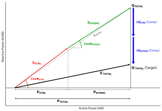
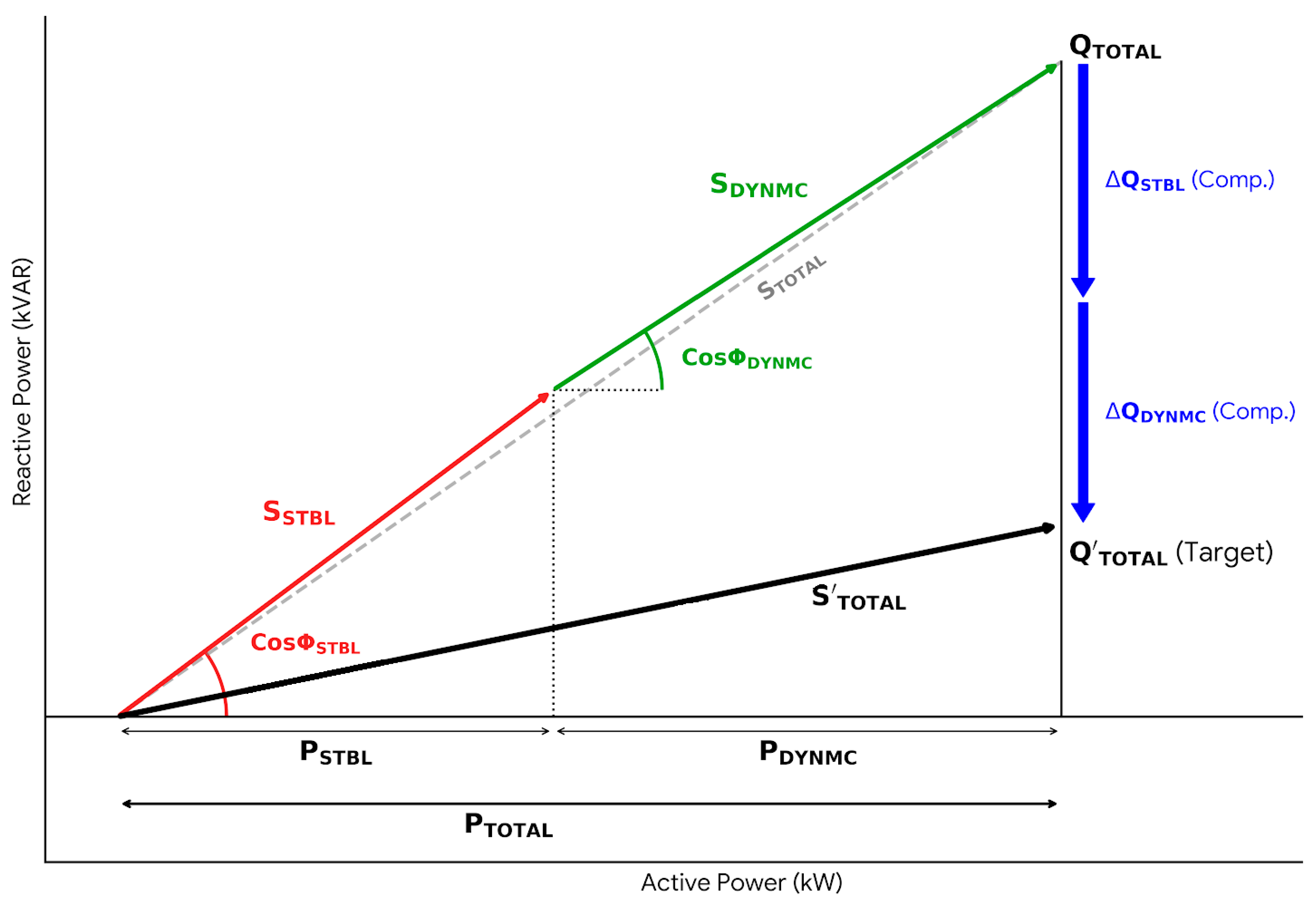
To implement the hybrid compensation strategy on a DESV, a two-layer calculation methodology must be developed. The total reactive power (QTOTAL) is partitioned into a static layer (QSTBL) and a dynamic layer (QDYNMC). The hybrid compensation scheme is shown graphically in Figure 3. Within the context of this discussion, electrical loads that are withdrawn from the system, such as auxiliary machinery, navigation, and hotel loads, may exhibit changes at significantly smaller magnitudes in comparison to thrusters. In terms of the dynamics of the system, this has been determined to be stable.
Figure 3.
Hybrid compensation scheme for stable and dynamic loads.
3.3.1. Static Layer Calculation (Constant Loads)
The static layer is designed to cover the fixed and continuous electrical loads of the ship. In a DESV, these typically include auxiliary machinery (cooling pumps and fuel oil separators), bridge electronics, and hotel loads (HVAC, lighting, and galley). These loads are characterized by a relatively stable active power PSTBL and a constant PF Cos ΦSTBL.
The required static compensation ΔQSTBL to reach a target PF Cos ΦSTBL_AIM is:
ΔQSTBL = PSTBL × [Tg (Arcos (Cos ΦSTBL)) − Tg (Arccos (Cos ΦSTBL_AIM))]
3.3.2. Dynamic Layer Calculation (Non-Linear and Variable Loads)
The dynamic layer addresses the propulsion system, which consists of four high-power asynchronous motors. These motors are the largest consumers on the vessel and exhibit highly variable PFs depending on their load factor and the presence of VFD control. The dynamic compensation QDYNMC must be sized to handle the maximum variance in reactive power demand during transients.
For induction motors, the PF can drop significantly at low loads (e.g., from 0.85 at full load to 0.20 at no load [50]). The SVG module calculates the instantaneous reactive current Ir and injects an equal and opposite current to neutralize the lag. The dynamic capacity QDYNMC is calculated based on reactive demand provided by the dynamic layer:
ΔQDYNMC = PDYNMC × [Tg (Arcos (Cos ΦSTBL)) − Tg (Arccos (Cos ΦSTBL_AIM))]
3.3.3. Proposed Hybrid System Integration Methodology
The total system compensation ΔQTOTAL at any given time t is the sum of the contributions from the static steps and the dynamic layer:
ΔQTOTAL = ΔQSTBL + ΔQDYNMC
For marine applications, the target PF is usually set between 0.85 and 0.90 to avoid the risks of over-compensation and self-excitation in motors [36,45,51].
Table 2.
Technical specifications of power sources for DESV.
3.4. Case Study: Analysis of a Diesel–Electric Supply Vessel
The proposed methodology is applied to a representative DESV. This vessel features redundant power generation and a distribution system designed to support high-intensity DESV tasks.
3.4.1. Vessel Configuration and Loads
The vessel’s power plant consists of four identical DGs, providing a total installed capacity for propulsion, auxiliary systems, and hotel loads. Table 2 lists the specifications of power sources, and Table 3 lists the loads of auxiliary machines and hotel load for a DESV in operation.
The electrical loads are categorized into propulsion, auxiliary, and hotel services.
- Auxiliary machinery, bridge, and hotel loads (static loads): compressor, pumps, navigation systems, communication, lighting, HVAC, etc.
- Propulsion system (dynamic loads): 2 × asynchronous (induction) motors for starboard and port configuration. The features of asynchronous (induction) motors for thrusters are shown in Table 4.
Electrical loads for auxiliary and hotel services do not change significantly during navigation. Additionally, some electrical loads are not activated during navigation and operation. Therefore, the load factor coefficient has been accepted as zero for some loads. Other auxiliary machinery loads have also been drafted as approximate values based on the equipment used on the supply vessel.
Table 3.
Electrical loads of auxiliary machines and hotel load for a DESV in operation mode.
Table 4.
Technical specifications of asynchronous (induction) motors for thrusters.
3.4.2. Operational Mode Analysis
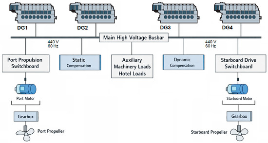
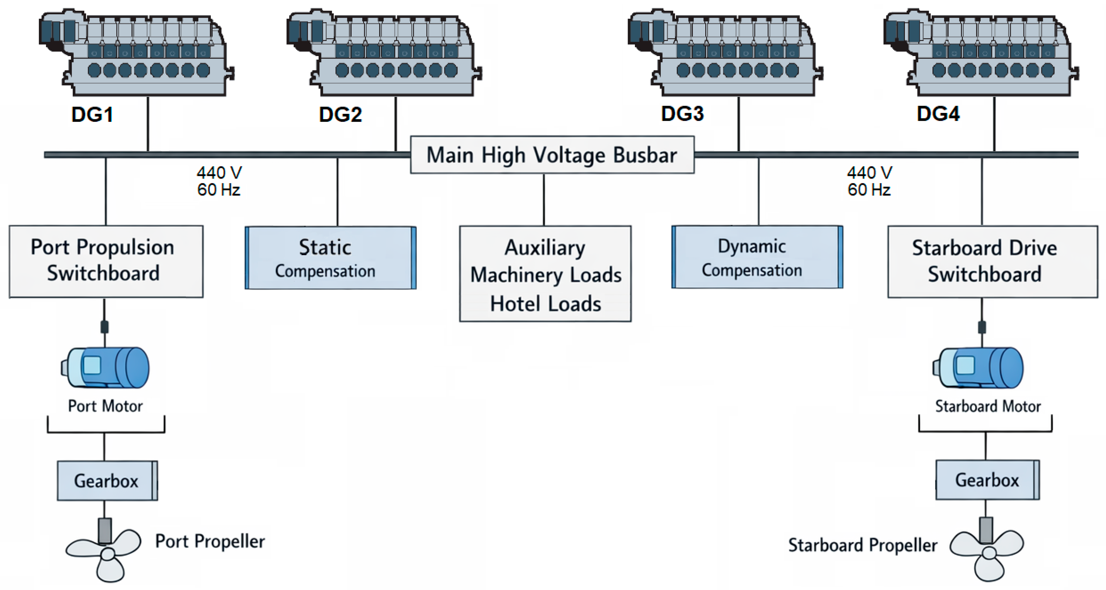
The beginning of this section establishes the framework for evaluating the vessel’s performance, focusing specifically on the assessment of PF and efficiency across varying conditions. It introduces a quantitative analysis of the proposed HRPC system, which is tested across three distinct operating profiles designated as Operation-I, Operation-II, and Operation-III to capture different load behaviors. The HRPC diagram proposed for DESV is shown schematically on the main high-voltage busbar in Figure 4. Proposed HRPC diagram for a DESV. The representation of DGs and compensation methods is presented with thrusters and auxiliary machines.
Figure 4.
Proposed HRPC diagram for a DESV.
The section concludes by defining the specific metrics and benchmarks used to measure the system’s success, specifically the reduction in fuel consumption and the corresponding decrease in CO2 emissions. It details the experimental setup where the system is evaluated against three target PF values (0.90, 0.95, and 0.98) and compared to a baseline uncompensated system operating at a PF of approximately 0.84–0.87.
In the preparation of this article, the authors utilized generative artificial intelligence tools to enhance the quality and technical execution of this study. Specifically, these tools were employed to assist in the refinement of illustrative graphics and ensure grammatical accuracy and stylistic coherence through text editing. The authors have meticulously reviewed, verified, and edited all AI-generated content to ensure accuracy and scientific integrity, taking full responsibility for the final published material.
4. Results
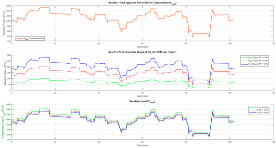
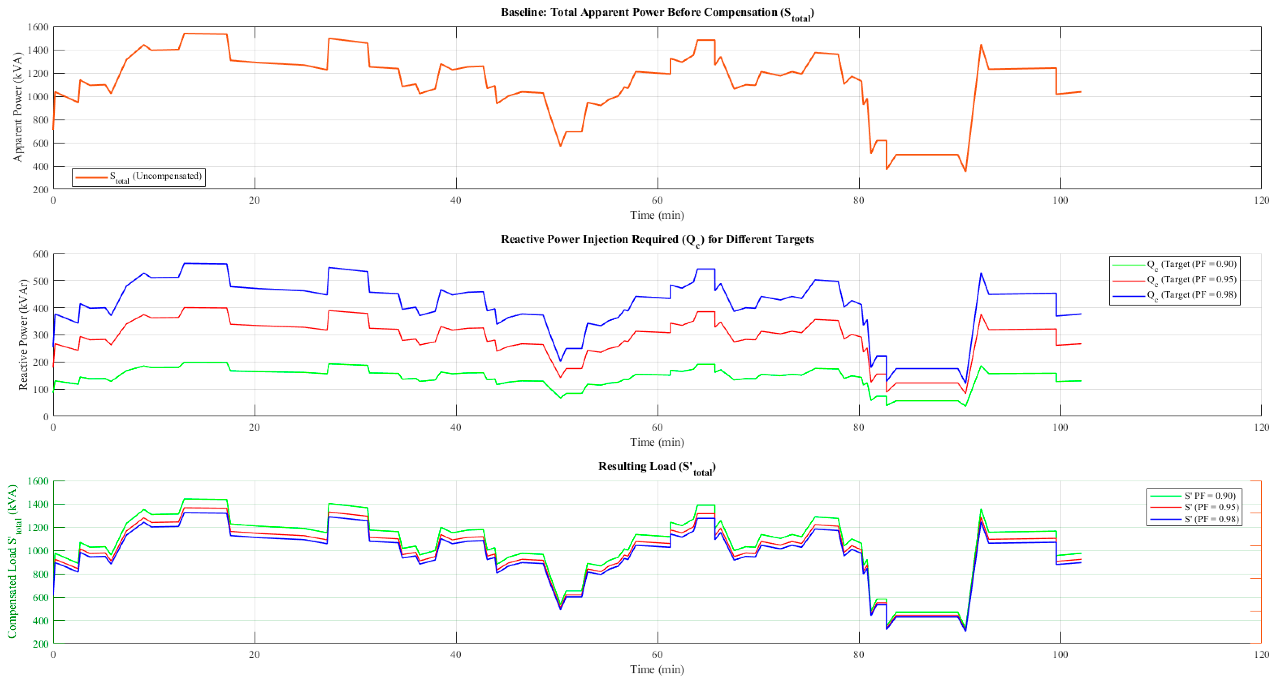
This section presents the quantitative analysis of the proposed HRPC system across three distinct operational profiles (Operation-I, Operation-II, and Operation-III). The performance was evaluated based on fuel consumption reduction and the consequent mitigation of CO2 emissions. The system was tested against three target PF values: 0.90, 0.95, and 0.98, compared against a baseline uncompensated system operating at an average PF ≈ 0.84–0.87. The HRPC data from Operation-III were analyzed in the MATLAB R2023b for each of the separate PF values of 0.90, 0.95, and 0.98, and the comparative graph is shown in Figure 5.
Figure 5.
Graphic of HRPC analysis in Operation-III (PF = 0.90, 0.95, and 0.98).
4.1. Operational Fuel Consumption Analysis
The implementation of dynamic PFC demonstrated a consistent and significant reduction in fuel consumption across all operational profiles. The fuel usage was calculated based on a constant SFOC of 210.0 g/kWh for the generator set.
The results of the multiple scenarios of the HRPC analysis were calculated for PF values of 0.90, 0.95, and 0.98 and are detailed in Table 5.
For Operation-I, which represented the highest load profile with a baseline consumption of 805.749 L, the compensation strategies yielded the following results:
- Target PF = 0.90: Fuel consumption decreased to 755.319 L, representing savings of 6.259% (50.430 L).
- Target PF = 0.95: Consumption was further reduced to 715.565 L, a saving of 11.193% (90.184 L).
- Target PF = 0.98: The system achieved optimal efficiency with a consumption of 693.660 L, yielding a total reduction of 13.911% (112.089 L).
Operation-II and Operation-III exhibited nearly identical efficiency trends, validating the system’s robustness across varying load magnitudes. Operation-II (baseline 736.744 L) achieved a maximum reduction of 13.953% at the 0.98 target. Operation-III, the lowest load profile (baseline 484.886 L), achieved a maximum reduction of 13.858%.
Table 5.
Results for multiple scenarios of HRPC analysis (PF = 0.90, 0.95, and 0.98).
4.2. Environmental Impact and Decarbonization
The environmental impact was assessed using a carbon factor (CF) of 3.114, in accordance with ANNEX 12 RESOLUTION MEPC.350(78) guidelines. The reduction in apparent power demand (STOTAL) directly correlated with a decrease in carbon emissions.
The data indicate a linear relationship between fuel savings and emission reductions. For the aggregate of all operations, shifting the PF target from 0.90 to 0.98 resulted in an approximate doubling of the emission reduction efficiency. Specifically, in Operation-I, the CO2 emission reduction improved from 6.259% at PF = 0.90 to 13.911% at PF = 0.98. This confirms that higher compensation targets are essential for maximizing the EEXI performance of diesel–electric ships.
4.3. Interpretation of Compensation Efficiency
The experimental results indicate diminishing marginal returns as the PF approaches unity, which is consistent with the trigonometric nature of power triangles.
- The transition from uncompensated (≈0.84) to PF = 0.90 yielded a ~6.3% efficiency gain.
- The transition from 0.90 to 0.95 added a further ~4.9% gain.
- The transition from 0.95 to 0.98 added a further ~2.7% gain.
Despite the slight tapering in marginal gain, the absolute reduction at PF = 0.98 remains technically and economically viable. The calculations show that maintaining the target PF required precise dynamic adjustments of capacitive reactive power (QC), ranging from minimal injection during low loads to substantial correction during peak demands.
4.4. Experimental Conclusions
The data conclusively support the integration of the proposed compensation system. The varying operational profiles (I, II, and III) did not negatively impact the system’s ability to reduce apparent power. The standard deviation in percentage savings across different operations for the same target PF was negligible (<0.1%), indicating high system stability.
The fuel savings (in liters) scaled linearly with the total energy demand of the operation, suggesting the solution is scalable to vessels with higher power requirements. While PF = 0.95 offers substantial benefits (savings of over 11%), pushing the target to 0.98 maximizes the decarbonization potential (≈14% savings) without introducing system instability, as evidenced by the successful load flow calculations in the operational logs.
5. Discussion
This study analyzed the efficacy of an HRPC strategy applied to a DESV. By integrating static capacitor banks with dynamic compensation, the system addresses the specific challenges of AC microgrids characterized by high-power inductive loads and non-linear propulsion drives. The following subsections discuss the implications of the simulation results regarding electrical stability, fuel economy, environmental compliance, and future research directions.
In SMGs, auxiliary machinery and cruise loads are consistently drawn at a constant rate during navigation, irrespective of variations in load during ship maneuvering or operation. A static compensation system is recommended to offset the reactive loads gathered by the system, while a dynamic compensation system is suggested for thrust loads that differ at specific intervals during operation and maneuvering situations. Consequently, static compensation is advised for loads that remain constant during navigation, whereas dynamic compensation is suggested for amounts that alter continuously during operations.
5.1. Enhancement of Generator Efficiency and Load Optimization
The primary technical benefit observed in this study is the substantial reduction in the apparent power (S) demand placed on the vessel’s DGs. In uncompensated diesel–electric systems, induction motors and converters draw significant reactive current, forcing the generators to operate at a low PF, often between 0.82 and 0.85. This necessitates the running of additional generators solely to support the reactive load (kVAR), even if the active power (kW) demand does not require it.
The calculation results indicate that by elevating the target PF to 0.98 via hybrid compensation, the apparent power demand was reduced by approximately 16% to 19% across the analyzed scenarios. This reduction has profound implications for the vessel’s power management system (PMS). In high-load scenarios (Operation-I), the reduction in kVA demand enables the PMS to take one DG offline (e.g., operating three units instead of four) without compromising the spinning reserve. Consequently, the remaining online generators operate at a higher load percentage, shifting their working point to a more optimal region of the SFOC curve. This aligns with findings by Su et al. [27], which suggest that correcting the PF not only releases system capacity but also significantly improves the operating efficiency of diesel engines by reducing thermal losses in alternators and distribution cables.
5.2. Economic Analysis of Fuel Consumption
The quantitative analysis of fuel consumption across three operational modes (Operation-I, -II, and -III) highlights the economic viability of the proposed hybrid architecture. As detailed in the calculation results, the system achieved consistent fuel savings when the PF was compensated from a baseline of ~0.84 to 0.98.
- Operation-I: The total GenSet fuel usage decreased from 805.749 L (uncompensated) to 693.660 L (compensated to PF 0.98). This represents a saving of 112.089 L, or a 13.91% reduction in fuel consumption.
- Operation-II: Fuel consumption dropped from 736.744 L to 633.950 L, yielding a 13.95% reduction (102.795 L).
- Operation-III: Even in lower load conditions, the system saved 67.197 L, equating to a 13.86% reduction.
It is noteworthy that the marginal gain between compensating for PF 0.90 versus PF 0.98 is significant. For instance, in Operation-I, compensating only to 0.90 resulted in a 6.26% saving, whereas optimizing it to 0.98 more than doubled the savings to 13.91%. This non-linear benefit justifies the implementation of precise dynamic compensation alongside static banks to achieve near-unity PFs, rather than settling for standard correction levels.
5.3. Environmental Impact and Regulatory Compliance (IMO)
The reduction in fuel consumption correlates directly with a decrease in GHG emissions, a critical metric for compliance with the IMO regulations. The study results show that CO2 emissions were reduced by the same percentages as fuel consumption (approx. 13.9% for Operation-I).
For DESVs, which often operate in modes with high auxiliary consumption, these reductions are vital for meeting the EEXI and improving the CII rating. By reducing the auxiliary power required from the generators, the vessel improves its energy efficiency per transport work metric, ensuring that the vessel maintains its operational safety margins without excessive carbon emissions. This supports the maritime industry’s broader goal of reaching net-zero emissions by 2050 by maximizing the efficiency of existing diesel–electric assets before the widespread adoption of zero-carbon fuels.
5.4. Limitations and Future Work
While this study demonstrates the effectiveness of HRPC through simulation based on real operational data, several avenues for future research remain. First, the current study focused primarily on fundamental frequency reactive power. However, diesel–electric vessels with extensive VFDs are prone to significant harmonic distortion. Future studies should include a detailed analysis to quantify the active filtering capabilities of the SVG module within the hybrid topology, including assessments related to other AC power systems for systems that generate harmonics and disturbances as a result of non-linear transient changes [52].
Secondly, as the maritime sector moves toward hybridization, the integration of the compensation system with energy storage systems (ESSs) presents a promising frontier. Future research should investigate architectures where the DC (direct current) link of the SVG is coupled with battery storage. This would allow the system to perform simultaneous RPC and active power peak-shaving, further flattening the generator load profile and enhancing response to pulsed loads common in supply vessels.
Finally, experimental validation on a physical testbed or a pilot vessel is recommended to assess the long-term reliability of the control algorithms under harsh marine environmental conditions, such as vibration and temperature fluctuations.
In this analysis, capital investment and operating expenses are not taken into consideration. In the course of following inquiries, it would be prudent to carry out an economic evaluation.
In summary, the HRPC approach offers a robust solution for modern DESVs. It transcends simple PFC by acting as a comprehensive grid stability and energy efficiency tool. By alleviating generator stress, significantly cutting fuel consumption by over 13%, and ensuring stricter compliance with IMO emission standards, this technology serves as a critical enabler for the sustainable operation of the diesel–electric fleet.
6. Conclusions
This work extensively examined an HRPC technique for DESVs, which have significantly varied load profiles from steady-state cruising to high-intensity DP. The study found that static compensation approaches are insufficient for non-linear power circuits and variable frequency motors in SMGs. The suggested hybrid architecture improves PQ and operational stability by using static capacitor banks for baseload reactive demand and dynamic compensation for quick transient variations.
Based on real operational data, the simulation findings show significant quantitative gains. Optimizing the PF from 0.82–0.84 to 0.98 reduced fuel usage by 13.91% (112.1 L) in Operation-I, the cruising scenario. Additionally, the hybrid technique lowered generator apparent power demand by around 6–14%. Due to this reduction, the PMS can optimize generator loading and allow the vessel to operate with three generators instead of four during specific load conditions, shifting engine operation to a more efficient point on the SFOC curve.
This study examined DESVs; however, the hybrid compensation methodology can be applied to tugboats, ferries, and offshore construction vessels with complex load profiles. By decoupling static and dynamic compensation, a scalable solution that balances cost and performance is available across the maritime sector.
Efficiency increases affect IMO decarbonization framework compliance. Fuel consumption reduction and power demand optimization immediately improve the vessel’s CII rating and EEXI. The hybrid compensation technique allows shipowners to meet stricter environmental rules without compromising operating capabilities by minimizing the carbon footprint per transit task. The EEDI (Energy Efficiency Design Index) targets new ship designs, but these concepts of reduced auxiliary power demand and enhanced main engine efficiency apply to new constructions.
Author Contributions
Conceptualization, E.F. and M.N.; methodology, E.F. and M.N.; software, E.F.; validation, E.F. and M.N.; formal analysis, E.F.; investigation, E.F. and M.N.; data curation, M.N.; writing—original draft preparation, E.F. and M.N.; writing—review and editing, E.F. and M.N.; visualization, E.F. All authors have read and agreed to the published version of the manuscript.
Funding
This research received no external funding.
Data Availability Statement
All data and materials are available on request from the corresponding author. The data are not publicly available due to ongoing studies using a part of the data.
Acknowledgments
During the preparation of this research, the author(s) used PhD thesis data from Erdem Fikir under the supervision of Mustafa NURAN for the purposes of analyzing the power quality and efficiency of electric power systems in marine vessels. In the preparation of this article, the authors used artificial intelligence tools for purposes such as editing grammar and drawing diagrams. The authors have reviewed and edited the output and take full responsibility for the content of this publication.
Conflicts of Interest
The authors declare no conflicts of interest.
Abbreviations
The following abbreviations are used in this manuscript:
| IMO | International Maritime Organization |
| GHG | Greenhouse Gases |
| EEXI | Energy Efficiency Existing Ship Index |
| CII | Carbon Intensity Indicator |
| RPC | Reactive Power Compensation |
| HRPC | Hybrid Reactive Power Compensation |
| DG | Diesel Generator |
| GenSet | Diesel Generators Set |
| VFD | Variable Frequency Drive |
| PQ | Power quality |
| THD | Total Harmonic Distortion |
| EMC | Electromagnetic Compatibility |
| DP | Dynamic Positioning |
| PF | Power Factor |
| PFC | Power Factor Correction |
| SMG | Shipboard Microgrid |
| DESV | Diesel–Electric Supply Vessel |
| SFOC | Specific Fuel Consumption Rate |
| HVAC | Heating, Ventilation and Air-Conditioning |
| AC | Alternating Current |
| DC | Direct Current |
| EMI | Electromagnetic Interference |
| SVG | Static Var Generator |
| STATCOM | Static Synchronous Compensator |
| VSC | Voltage Source Converter |
| IGBT | Insulated Gate Bipolar Transistor |
| EEDI | Energy Efficiency Design Index |
| PMS | Power Management System |
References
- IMO Strategy on Reduction of GHG Emissions from Ships. Available online: https://www.imo.org/en/ourwork/environment/pages/imo-strategy-on-reduction-of-ghg-emissions-from-ships.aspx (accessed on 17 November 2025).
- United Nations. Review of Maritime Transport-Navigating Maritime Chokepoints; United Nations Publications: New York, NY, USA, 2024; ISBN 9789210032063. Available online: https://unctad.org/system/files/official-document/rmt2024_en.pdf (accessed on 20 November 2025).
- Nuran, M.; Bayraktar, M.; Yuksel, O. Simulation of a Hybrid Propulsion System on Tugboats Operating in the Strait of Istanbul. Sustainability 2025, 17, 5834. [Google Scholar] [CrossRef] [Scilit]
- Mindykowski, J.; Szmit, E.; Tarasiuk, T. Electric Power Quality and Ship’s Safety. Pol. Acad. Sci. Branch Gdan. Mar. Technol. Trans. 2004, 15, 351–360. [Google Scholar]
- Dixon, J.; Morán, L.; Rodríguez, J.; Domke, R. Reactive Power Compensation Technologies: State-of-the-Art Review. Proc. IEEE 2005, 93, 2144–2163. [Google Scholar] [CrossRef] [Scilit]
- Mindykowski, J.; Tarasiuk, T.; Rupnik, P. Problems of passive filters application in system with varying frequency. In 2007 9th International Conference on Electrical Power Quality and Utilisation; IEEE: Piscataway, NJ, USA, 2007. [Google Scholar] [CrossRef] [Scilit]
- Mindykowski, J.; Tarasiuk, T. Development of DSP-Based Instrumentation for Power Quality Monitoring on Ships. Measurement 2010, 43, 1012–1020. [Google Scholar] [CrossRef] [Scilit]
- Gnacinski, P.; Mindykowski, J.; Tarasiuk, T. A New Concept of the Power Quality Temperature Factor and Its Experimental Verification. IEEE Trans. Instrum. Meas. 2008, 57, 1651–1660. [Google Scholar] [CrossRef] [Scilit]
- Tarasiuk, T. A Few Remarks about Assessment Methods of Electric Power Quality on Ships-Present State and Further Development. Measurement 2009, 42, 1153–1163. [Google Scholar] [CrossRef] [Scilit]
- Bidram, A.; Davoudi, A. Hierarchical Structure of Microgrids Control System. IEEE Trans. Smart Grid 2012, 3, 1963–1976. [Google Scholar] [CrossRef] [Scilit]
- Hofmann, W.; Schlabbach, J.; Just, W. Reactive Power Compensation a Practical Guide; John Wiley & Sons, Ltd.: West Sussex, UK, 2012; ISBN 9780470977187. [Google Scholar]
- Pilat, A.; Tarasiuk, T. Comparative Analysis of Power Quality on Bus-Bars of the Main Switchboard and Terminal of Exemplary Load at Marine Microgrid. In 2014 International Conference and Exposition on Electrical and Power Engineering; IEEE: Piscataway, NJ, USA, 2014; pp. 764–768. [Google Scholar] [CrossRef] [Scilit]
- Vyshnevskyi, L.; Mukha, M.; Veretennik, O.; Drankova, A.; Kozyryev, I.; Vyshnevskyi, O. Dynamic Compensation of Reactive Power in Ship Power Plants. TransNav-Int. J. Mar. Navig. Saf. Sea Transp. 2025, 19, 537–541. [Google Scholar] [CrossRef] [Scilit]
- Prousalidis, J.; Antonopoulos, G.; Mouzakis, P.; Sofras, E. On Resolving Reactive Power Problems in Ship Electrical Energy Systems. J. Mar. Eng. Technol. 2015, 14, 124–136. [Google Scholar] [CrossRef] [Scilit]
- Mahdavi, N.; Ali, T.; Aghbolaghi, J.; Bizon, N.; Blaabjerg, F. Power Systems Reactive Power Control in AC Power Systems Fundamentals and Current Issues; Springer: Cham, Switzerland, 2017; ISBN 978-3-319-51118-4. [Google Scholar]
- Anaya, K.L.; Pollitt, M.G. Reactive Power Procurement: A Review of Current Trends. Appl. Energy 2020, 270, 114939. [Google Scholar] [CrossRef] [Scilit]
- Sauer, P.W. Reactive Power and Voltage Control Issues in Electric Power Systems. In Applied Mathematics for Restructured Electric Power Systems; Chow, J.H., Wu, F.F., Momoh, J.A., Eds.; Springer: New York, NY, USA, 2006; pp. 11–24. [Google Scholar] [CrossRef] [Scilit]
- Mindykowski, J. Power Quality on Ships: Today and Tomorrow’s Challenges. In 2014 International Conference and Exposition on Electrical and Power Engineering; IEEE: Piscataway, NJ, USA, 2014. [Google Scholar] [CrossRef] [Scilit]
- Barros, J.; Diego, R.I. A Review of Measurement and Analysis of Electric Power Quality on Shipboard Power System Networks. Renew. Sustain. Energy Rev. 2016, 62, 665–672. [Google Scholar] [CrossRef] [Scilit]
- Nguyen, H.P.; Hoang, A.T.; Nizetic, S.; Nguyen, X.P.; Le, A.T.; Luong, C.N.; Chu, V.D.; Pham, V.V. The Electric Propulsion System as a Green Solution for Management Strategy of CO2 Emission in Ocean Shipping: A Comprehensive Review. Int. Trans. Electr. Energy Syst. 2021, 31, e12580. [Google Scholar] [CrossRef] [Scilit]
- Xie, P.; Tan, S.; Bazmohammadi, N.; Guerrero, J.M.; Vasquez, J.C. A Real-Time Power Management Strategy for Hybrid Electrical Ships Under Highly Fluctuated Propulsion Loads. IEEE Syst. J. 2023, 17, 395–406. [Google Scholar] [CrossRef] [Scilit]
- Gao, J.; Lan, H.; Cheng, P.; Hong, Y.Y.; Yin, H. Optimal Scheduling of an Electric Propulsion Tugboat Considering Various Operating Conditions and Navigation Uncertainties. J. Mar. Sci. Eng. 2022, 10, 1973. [Google Scholar] [CrossRef] [Scilit]
- Guerrero, J.M.; Jin, Z.; Liu, W.; Othman, M.B.; Savaghebi, M.; Anvari-Moghaddam, A.; Meng, L.; Vasquez, J.C. Shipboard Microgrids: Maritime Islanded Power Systems Technologies. In PCIM Asia 2016; International Exhibition and Conference for Power Electronics, Intelligent Motion, Renewable Energy and Energy Management; VDE: Frankfurt am Main, Germany, 2016; pp. 135–142. ISBN 978-3-8007-4227-1. [Google Scholar]
- Prousalidis, J.; Styvaktakis, E.; Hatzilau, I.K.; Kanellos, F.; Perros, S.; Sofras, E. Electric Power Supply Quality in Ship Systems: An Overview. Int. J. Ocean Syst. Manag. 2008, 1, 68–83. [Google Scholar] [CrossRef] [Scilit]
- Tsvetanov, D.; Djagarov, N.; Grozdev, Z.; Djagarova, J. Harmonic Compensation in Ship Power System Using P-q Theory Control Based Shunt Active Power Filter. In 8th International Conference on Energy Efficiency and Agricultural Engineering; IEEE: Piscataway, NJ, USA, 2022; pp. 1–10. [Google Scholar] [CrossRef] [Scilit]
- Bhujade, R.; Khambadkone, A.M.; Maharjan, S.; Mohzani, Z. Optimal Operation and Sizing of Energy Storage System for a Ship Electrical Power System. In IEEE International Conference on Electrical Systems for Aircraft, Railway, Ship Propulsion and Road Vehicles and International Transportation Electrification Conference; IEEE: Piscataway, NJ, USA, 2022. [Google Scholar] [CrossRef] [Scilit]
- Su, C.L.; Lin, M.C.; Liao, C.H. A Method for Evaluating Energy Efficiency to Justify Power Factor Correction in Ship Power Systems. IEEE Trans. Ind. Appl. 2013, 49, 2773–2782. [Google Scholar] [CrossRef] [Scilit]
- Tsekouras, G.J.; Kanellos, F.D.; Prousalidis, J. Simplified Method for the Assessment of Ship Electric Power Systems Operation Cost Reduction from Energy Storage and Renewable Energy Sources Integration. IET Electr. Syst. Transp. 2015, 5, 61–69. [Google Scholar] [CrossRef] [Scilit]
- Babaei, M.; Jafari-Marandi, R.; Abdelwahed, S.; Smith, B. Application of STATCOM for MVDC Shipboard Power System. In 2017 IEEE Electric Ship Technologies Symposium; IEEE: Piscataway, NJ, USA, 2017; pp. 142–147. [Google Scholar] [CrossRef] [Scilit]
- Ni, K.; Hu, Y.; Li, X. An Overview of Design, Control, Power Management, System Stability and Reliability in Electric Ships. Power Electron. Drives 2017, 2, 5–29. [Google Scholar] [CrossRef]
- Li, W.; Zhao, H.; Zhu, J.; Yang, T. A Novel Reactive Power Sharing Control Strategy for Shipboard Microgrids Based on Deep Reinforcement Learning. J. Mar. Sci. Engenering 2025, 13, 718. [Google Scholar] [CrossRef] [Scilit]
- Ding, Y.; Zhao, K.; Duan, J.; Sun, L. Proactive Power Compensation Strategy of Pulsed Load for Transient Ride-Through of Ship Microgrid. Electronics 2025, 14, 4665. [Google Scholar] [CrossRef] [Scilit]
- Romero, G.; Martinez, L. Electrical Generation and Distribution Systems and Power Quality Disturbances; InTechOpen: Rijeka, Croatia, 2011; ISBN 978-953-51-4397-0. [Google Scholar]
- Mindykowski, J.; Tarasiuk, T. Problems of Power Quality in the Wake of Ship Technology Development. Ocean. Eng. 2015, 107, 108–117. [Google Scholar] [CrossRef] [Scilit]
- Spathis, D.; Nikolopoulou, E.; Dallas, S.; Prousalidis, J.; Kladas, A.; Tatakis, E.; Pallis, I.; Beniakar, M.; Kanellos, F.; Sarigiannidis, A. Analysis of Various Power Quality Phenomena in a Highly Electrified Vessel. In 2015 IEEE Electric Ship Technologies Symposium (ESTS); IEEE: Piscataway, NJ, USA, 2015; pp. 420–426. [Google Scholar] [CrossRef] [Scilit]
- Zobaa, A.F.; Abdel Aleem, S.H.E. Power Quality in Future Electrical Power Systems; The Institution of Energy and Technology: London, UK, 2017; ISBN 9781523123209. [Google Scholar]
- Czarnecki, L.S. Budeanu and Fryze: Two Frameworks for Interpreting Power Properties of Circuits with Nonsinusoidal Voltages and Currents. Electr. Eng. 1997, 80, 359–367. [Google Scholar] [CrossRef] [Scilit]
- Liu, Y.W.; Rau, S.H.; Wu, C.J.; Lee, W.J. Improvement of Power Quality by Using Advanced Reactive Power Compensation. IEEE Trans. Ind. Appl. 2018, 54, 18–24. [Google Scholar] [CrossRef] [Scilit]
- Tarnapowicz, D.; German-Galkin, S.; Staude, M. Investigation Concerning the Excitation Loss of Synchronous Generators in a Stand-Alone Ship Power Plant. Energies 2021, 14, 2828. [Google Scholar] [CrossRef] [Scilit]
- Terriche, Y.; Lashab, A.; Çimen, H.; Guerrero, J.M.; Su, C.L.; Vasquez, J.C. Power Quality Assessment Using Signal Periodicity Independent Algorithms–A Shipboard Microgrid Case Study. Appl. Energy 2022, 307, 118151. [Google Scholar] [CrossRef] [Scilit]
- Li, G.; Song, W.; Liu, X. A Dynamic Reactive Power Control Strategy of LC-Type Energy Storage Converter for Achieving Zero Reactive Power and Improving Power Quality. In 6th International Conference on Energy, Electrical and Power Engineering; IEEE: Piscataway, NJ, USA, 2023; pp. 660–665. [Google Scholar] [CrossRef] [Scilit]
- Patel, M.R. Shipboard Electrical Power Systems, 2nd Edition; CRC Press: Boca Raton, FL, USA, 2022; ISBN 9780367430351. [Google Scholar]
- Awasthi, V.M.; Huchche, V.A. Reactive Power Compensation Using D-STATCOM. In International Conference on Energy Efficient Technologies for Sustainability; IEEE: Piscataway, NJ, USA, 2016; pp. 583–585. [Google Scholar] [CrossRef] [Scilit]
- Sah, P.; Singh, B.K. Power Quality Improvement Using Distribution Static Synchronous Compensator. Comput. Electr. Eng. 2023, 106, 108599. [Google Scholar] [CrossRef] [Scilit]
- Mutarraf, M.U.; Guan, Y.; Terriche, Y.; Su, C.L.; Nasir, M.; Vasquez, J.C.; Guerrero, J.M. Adaptive Power Management of Hierarchical Controlled Hybrid Shipboard Microgrids. IEEE Access 2022, 10, 21397–21411. [Google Scholar] [CrossRef] [Scilit]
- Aboelezz, A.M.; Sedhom, B.E.; El-Saadawi, M.M.; Eladl, A.A.; Siano, P. State-of-the-Art Review on Shipboard Microgrids: Architecture, Control, Management, Protection, and Future Perspectives. Smart Cities 2023, 6, 1435–1484. [Google Scholar] [CrossRef] [Scilit]
- Gangolu, S.; Sarangi, S.; Mohanty, R. Relay Algorithm for STATCOM Compensated Line Using Differential Current Ratio. Int. J. Electr. Power Energy Syst. 2024, 155, 109473. [Google Scholar] [CrossRef] [Scilit]
- Tarasiuk, T.; Gamini Jayasinghe, S.; Gorniak, M.; Pilat, A.; Shagar, V.; Liu, W.; Guerrero, J.M. Review of Power Quality Issues in Maritime Microgrids. IEEE Access 2021, 9, 81798–81817. [Google Scholar] [CrossRef] [Scilit]
- Gayatri, M.T.L.; Parimi, A.M.; Pavan Kumar, A.V. A Review of Reactive Power Compensation Techniques in Microgrids. Renew. Sustain. Energy Rev. 2018, 81, 1030–1036. [Google Scholar] [CrossRef] [Scilit]
- Gnacinski, P.; Tarasiuk, T.; Mindykowski, J.; Peplinski, M.; Gorniak, M.; Hallmann, D.; Pillat, A. Power Quality and Energy-Efficient Operation of Marine Induction Motors. IEEE Access 2020, 8, 152193–152203. [Google Scholar] [CrossRef] [Scilit]
- Mindykowski, J.; Tarasiuk, T.; Gnaciński, P. Review of Legal Aspects of Electrical Power Quality in Ship Systems in the Wake of the Novelisation and Implementation of Iacs Rules and Requirement. Energies 2021, 14, 3151. [Google Scholar] [CrossRef] [Scilit]
- Kukačka, L.; Kraus, J.; Kolár, M.; Dupuis, P.; Zissis, G. Review of AC Power Theories under Stationary and Non-Stationary, Clean and Distorted Conditions. IET Gener. Transm. Distrib. 2016, 10, 221–231. [Google Scholar] [CrossRef] [Scilit]
Disclaimer/Publisher’s Note: The statements, opinions and data contained in all publications are solely those of the individual author(s) and contributor(s) and not of MDPI and/or the editor(s). MDPI and/or the editor(s) disclaim responsibility for any injury to people or property resulting from any ideas, methods, instructions or products referred to in the content. |
© 2026 by the authors. Licensee MDPI, Basel, Switzerland. This article is an open access article distributed under the terms and conditions of the Creative Commons Attribution (CC BY) license.