


Abstract
To assess the feasibility of replacing titanium heat transfer plates with aluminum in ocean thermal energy conversion (OTEC) system heat exchangers, an investigative study on the resistance to seawater corrosion of aluminum plates was conducted. In this study, a long-term field corrosion test was conducted using deep seawater continuously supplied from an operational deep seawater facility in Kumejima, Japan. Flat A5052 aluminum plates with and without anodizing were installed in a plate heat exchanger, allowing corrosion behavior to be evaluated under realistic flow conditions for 12 months. The corrosion behavior of the plates was evaluated at 1, 3, 6, and 12 months. The results showed that, for the A5052 aluminum plates with anodizing, no apparent corrosion was observed on the anodized specimens throughout the test period. Although localized corrosion developed on the untreated specimens, the overall mass loss remained limited. Surface deposits containing inorganic and organic constituents were observed. The maximum corrosion rate of untreated A5052 was 2.56 × 10⁻² mm/y. Overall, the results suggest that anodized A5052 has potential as a heat-transfer material for OTEC systems under the tested conditions.
1. Introduction
This study was performed for the practical application of 1–10 MW class ocean thermal energy conversion (OTEC) systems as the next stage of the demonstration experiment. OTEC typically uses a “plate heat exchanger (PHE).” The cost of the PHE accounts for approximately one-third of the construction cost of the OTEC system. Therefore, improving the heat transfer performance of the heat exchanger leads to a reduction in construction cost in the OTEC. As OTEC uses ammonia and seawater as the working and heat source fluids, respectively, Kapranos [1] described titanium as the optimal material for heat-transfer plates owing to its corrosion resistance. Consequently, titanium is typically used as the heat-transfer surface for the PHE in OTEC systems. However, owing to the high manufacturing cost of titanium PHEs, alternative materials are required.
The authors focused on aluminum, which is less expensive than titanium, as a replacement material and considered its compatibility with ammonia. Incidentally, studies on the application of aluminum alloys to OTEC heat exchangers were originally conducted using the research facilities at the Natural Energy Laboratory of Hawaii Authority (NELHA). These studies established A5052 and A3003 as promising candidates but also revealed the persistent challenges of pitting and crevice corrosion in deep seawater (DSW). In particular, the use of aluminum materials in OTEC heat exchangers requires careful consideration of seawater-induced corrosion and biofouling. Dexter et al. [2], Foust [3], Darby [4], Larsen-Basse [5], Panchal et al. [6], Fitzpatrick et al. [7], Hihara et al. [8], Vega [9], Makai Ocean Engineering [10] and Vega [11] studied the influence of seawater corrosion on aluminum alloys employed in OTEC heat exchangers. Dexter et al. [2] evaluated the suitability of aluminum for OTEC applications by investigating the effects of seawater pH and dissolved oxygen on the corrosion rate of A5052. Foust [3] proposed the use of aluminum plate-fin type heat exchangers for OTEC applications, but noted that corrosion attacks and pitting caused by seawater are issues and emphasized the need for sufficient wall thickness in the heat exchanger. Darby [4] conducted seawater immersion corrosion tests on aluminum alloys, copper alloys, stainless steels, and titanium to investigate materials suitable for use in OTEC systems and observed that the corrosion rate of A5052 was slower than that of A3004. Larsen-Basse [5] performed seawater exposure tests for up to three years on five aluminum alloy materials, including Alclad (7072) 3003 and 3004, bare 3004, and 5052. The results indicated a low corrosion rate of approximately 3 µm/y in warm seawater (WSW). Although pitting corrosion was observed in all specimens exposed to DSW, the extent of corrosion was insufficient to penetrate the clad layer. Panchal et al. [6] conducted a study using Bare A3003, Bare A5052, Alclad A3004, Zinc A3003, and Alclad to build a technical certification database for aluminum alloys used in OTEC heat exchangers. They investigated the effects of the alloy type and surface treatment on seawater corrosion and demonstrated that Alclad exhibited the greatest wall thickness loss in cold seawater (CSW). Fitzpatrick et al. [7] conducted a five-year study to investigate the effects of seawater corrosion on aluminum materials used in seawater heat exchangers using bare AA-3003 and A7072-clad specimens. They observed that the material loss was greater in DSW than in surface seawater. Hihara et al. [8] investigated the corrosion behavior of Al 5052-H3 and Al 6061-T6 in ASTM artificial seawater and actual seawater environments. The results showed that, among the bare alloys, Al 5052-H3 possessed slightly superior corrosion resistance compared with Al 6061-T6. Among these studies, Vega [9] performed long-term corrosion exposure tests on Al 1100 H112, Al 3003-H14, and Al 5086-H116 in DSW under both near-stagnant and flowing conditions (1 m/s). The corrosion behavior of untreated specimens, WSW-pretreated specimens, and hypochlorite-treated specimens was compared. Among the treatments evaluated, hypochlorite treatment was found to be the most effective in mitigating pitting and/or crevice corrosion in Al 3003 and Al 5086. Makai Ocean Engineering [10] conducted a 10-year seawater corrosion program using several aluminum alloys, including A1100, A3003, A5052, A6063, LA83I, and LA83P, under WSW, CSW, and DSW exposure conditions. Overall, good corrosion resistance was observed in WSW, although localized pitting was found on some specimens. In CSW, corrosion behavior varied significantly among alloys and even among specimens of the same alloy. A3003 generally exhibited relatively minor pitting after 10 years of exposure, whereas A1100, LA83I, and LA83P showed severe pitting in several samples. A5052 and A6063 also exhibited considerable variability in corrosion performance. In DSW, both pitting corrosion and crevice corrosion became more pronounced, resulting in the most severe degradation among the tested environments. Furthermore, the study concluded that the corrosion performance of aluminum alloys in seawater was highly variable and difficult to predict. Based on the long-term seawater exposure results reported by Makai Ocean Engineering [10], Vega [11] summarized the applicability of aluminum heat exchangers for OTEC systems. The report suggested that heat exchangers fabricated from A3003 or A5052 could achieve service lives of up to approximately 15 years when used as WSW evaporators and about 10 years when used as DSW condensers. However, it also highlighted that brazed heat exchanger configurations may be susceptible to crevice corrosion under DSW conditions, which could limit long-term reliability.
The corrosion behavior of aluminum alloys in seawater environments has been extensively investigated over the past several decades. Zhang et al. [12] considered the application of aluminum materials in low-temperature multi-effect distillation desalination systems, examined the effects of copper and iron ions on the corrosion behavior of A5052 in NaCl solutions, and demonstrated that reduced pressure had a suppressive effect on corrosion. Peng et al. [13] investigated the influence of low-temperature sensitization of Al-Mg alloys on their corrosion behavior in seawater and clarified that the presence of Mg promoted the formation of a natural oxide film, thereby enhancing the corrosion resistance. Ji et al. [14] studied the effects of a two-year exposure on the surface film formation of 5083-series Al-Mg alloys in splash and tidal zones and reported that the environmental conditions in these zones influenced the film formation differently. Wang et al. [15] analyzed the corrosion characteristics of A5083 in seawater using electrochemical methods and showed that phosphate had an inhibitory effect on corrosion.
To mitigate seawater corrosion of aluminum alloys, various surface-treatment and coating technologies have been investigated. Hihara et al. [8] adopted HCLCoat11, HCLCoat13, and Alodine 1201 with epoxy/polyurethane topcoats for Al 5052-H3 and Al 6061-T6. HCLCoat11 and HCLCoat13 reduced the corrosion current density compared with the bare alloys, although pitting corrosion was not eliminated. The authors suggested that these thin ceramic-polymer coatings may be suitable for OTEC heat exchanger applications. Hagiwara [16] examined several types of surface-treated aluminum alloys immersed in seawater and observed their corrosion effects. To improve resistance to seawater corrosion, Kim et al. [17] investigated A2024 aluminum plates coated with nanoceramics using the acetic acid salt spray method and clarified the variations in pitting corrosion owing to the coating thickness. Yabuki et al. [18] employed a self-healing corrosion-protective treatment and demonstrated its effectiveness in preventing corrosion. Abdeslam et al. [19] demonstrated, through electrochemical analysis, that coating A2024-T3 with bisphenol S tetraglycidyl ether dianiline dipropoxy (TGEDADPDS) epoxy resin provides protection against NaCl-induced corrosion. Deflorian et al. [20] showed that applying environmentally friendly surface pretreatments, such as water-based paints and powder coatings, to aluminum alloys used in marine propulsion systems effectively protected them from seawater corrosion. Lin et al. [21] reported that coating A7075-T6 with conductive polymeric complexes enhanced its corrosion resistance in seawater.
Among these approaches, surface coatings have attracted particular attention because they can improve corrosion resistance without significantly affecting the thermal conductivity of aluminum heat exchangers. The authors also investigated the effects of PEEK resin and DLC [22] coatings on aluminum plates. Seawater flow experiments were conducted over five months using a PHE with aluminum plates surface-treated with PEEK resin and DLC. No changes were observed on the DLC-coated surfaces; however, localized peeling of the PEEK resin was observed. In addition, erosion was observed around the seawater inlet holes on both coated plates. Long-term seawater immersion tests with surface-treated aluminum are required to confirm the feasibility of using aluminum in PHEs for seawater applications. As reported by the author [23], a 12-month experimental study was conducted to evaluate the ammonia resistance of several coating systems on aluminum alloys, including PEEK resin, DLC coatings, anodized coatings, and composite anodized films. As anodized aluminum has been identified as the best coating method for improving ammonia corrosion resistance [23], it is expected to provide similar resistance to seawater.
Based on these findings, the authors investigated the seawater corrosion resistance of anodized aluminum alloys. In a previous study [24], long-term seawater flow tests were conducted using anodized A1050 heat-transfer plates, and the results demonstrated favorable corrosion resistance. However, for material selection in OTEC heat exchangers, evaluating only A1050 is insufficient. A5052 is an Al-Mg alloy that is widely recognized for its superior seawater corrosion resistance and has been repeatedly identified as a promising candidate in previous OTEC-related studies [2,3,4,5,6,7,8,9,10,11]. According to Darby [4], the seawater corrosion rate of A5052 pipes is approximately 1.0 × 10⁻² mm/year, indicating its potential for practical use as shown in Table 1. Several studies have also demonstrated that the seawater corrosion resistance of aluminum alloys can be further improved through appropriate surface treatments. Vega [9] reported that hypochlorite treatment effectively mitigated pitting and crevice corrosion in Al 5086 exposed to DSW, while Hihara et al. [8] showed that HCLCoat11 and HCLCoat13 coatings reduced the corrosion current density of aluminum alloys in seawater. These findings suggest that combining a corrosion-resistant alloy with an appropriate surface treatment may further enhance durability in marine environments.
Table 1.
Comparison of Corrosion Rates of A5052 under Various Seawater Conditions.
Among the available surface-treatment methods, anodizing is particularly attractive because it is a simple, well-established, and industrially practical process. Furthermore, our previous study demonstrated that anodized aluminum exhibits excellent resistance to ammonia corrosion [23]. Despite the extensive research on A5052 and various corrosion-protection methods, most previous studies have focused on the corrosion behavior of A5052 under static seawater exposure conditions. However, the heat transfer surfaces of OTEC heat exchangers are subjected to continuous seawater flow for extended periods, making long-term corrosion evaluation under flowing seawater conditions indispensable.
Therefore, the novelty of this work is twofold: (1) the investigation of the long-term corrosion behavior of A5052 during one year of continuous deep seawater circulation, and (2) the evaluation of the protective effect of anodizing treatment on A5052, which has not been sufficiently investigated under conditions relevant to OTEC heat exchanger applications. These results provide new insights into the applicability of anodized A5052 as a candidate heat-transfer material for OTEC systems.
Accordingly, the objective of the present study was to evaluate the seawater corrosion behavior of anodized A5052 under long-term deep seawater (DSW) exposure conditions. A plate heat exchanger equipped with flat A5052 aluminum plates, both with and without anodizing treatment, was operated in a DSW circulation facility. The specimens were exposed to DSW for 12 months, and their corrosion behavior was systematically evaluated.
2. Experimental Procedure
2.1. Experimental Apparatus
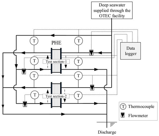
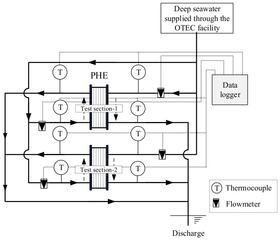
Figure 1 shows a schematic of the experimental apparatus. This apparatus consisted of two PHEs installed with the test specimens (Figure 2) and a DSW supply system. The seawater supply system was connected to the DSW pipeline of the Okinawa Prefectural Ocean Deep Water Research Center in Kumejima, Okinawa Prefecture. The DSW supplied to the test sections was obtained from the discharge line downstream of the OTEC condenser. Consequently, the seawater temperature was slightly higher than that of the intake deep seawater because of heat transfer within the OTEC facility. Seawater supplied to the experimental apparatus passed through the PHEs and was discharged into the ocean. To measure the temperature and flow rate of the seawater, a K-type thermocouple (Hayashi Denko, Tokyo, Japan: ST6-K-S1.6-150-3KX) and an ultrasonic flowmeter (Keyence Osaka, Japan: FD-Q10C, 0–30 L/min) were installed on the piping of the DSW supply system. The measurements were collected and recorded using a data logger (GRAPHTEC, Kanagawa, Japan: Midi LOGGER GL820).
Figure 1.
Schematic of experimental apparatus to flow seawater into two test sections (PHEs).
Figure 2.
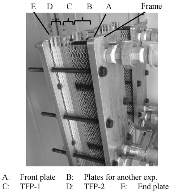
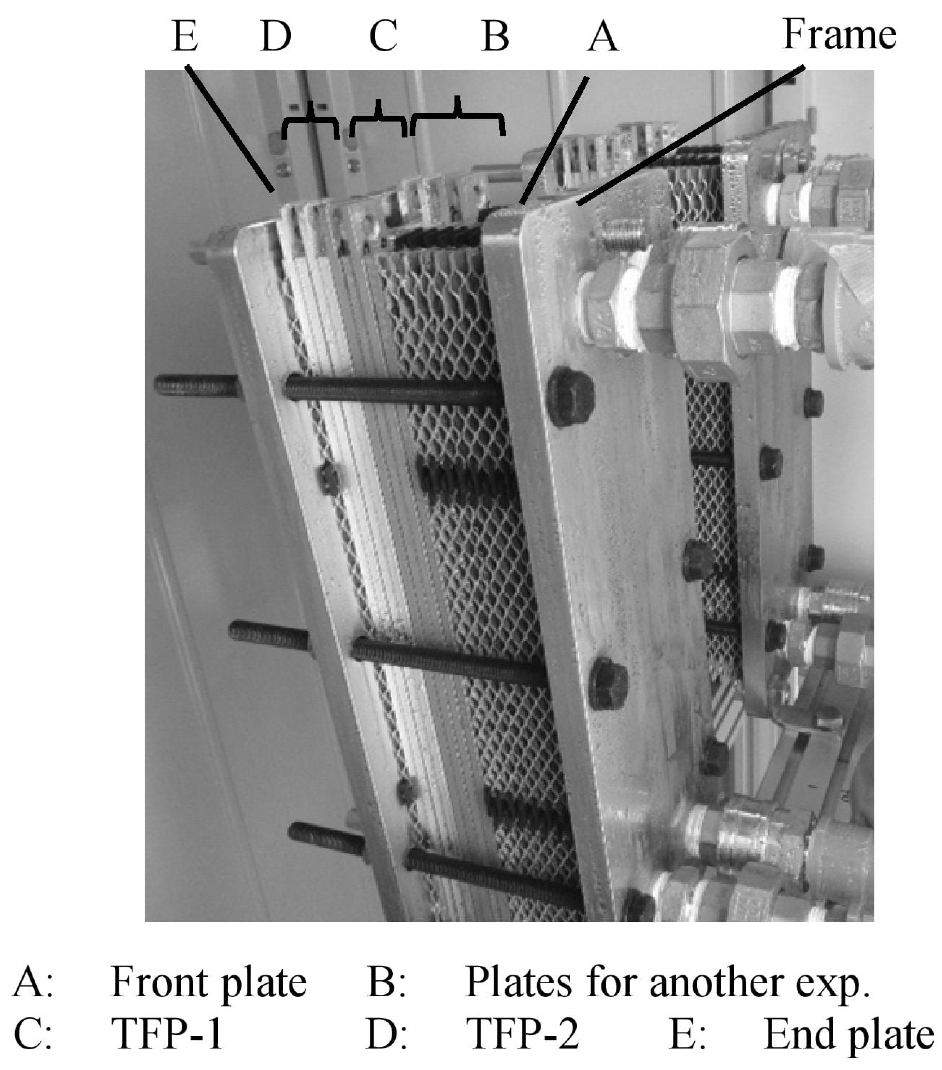
Configurations of test section with test specimens between two frames.
The test specimens obtained from the experiment were analyzed using the following equipment to measure the mass, observe the surface features, and identify the surface elements.
- Mass measurement: Electronic balance (Sartorius, Tokyo, Japan: TE1502S);
- Surface observation: Digital camera (RICOH, Tokyo, Japan: PENTAX K-S1);
- Enlarged surface observation was performed using a digital microscope (Keyence, Osaka, Japan: VHX-X1);
- Elemental surface analysis: Scanning electron microscopy/energy-dispersive X-ray spectroscopy (SEM/EDX, Hitachi High-Tech, Tokyo, Japan: SU5000);
- Simplified elemental surface analysis: laser-induced breakdown spectroscopy (Keyence, Osaka, Japan; EA-300 with VHX-X1);
- Analysis of corrosion products: Fourier Transform Infrared Spectroscopy (FTIR, Bruker, Kanagawa, Japan, VERTEX70-S).
2.2. Test Section and Test Plate
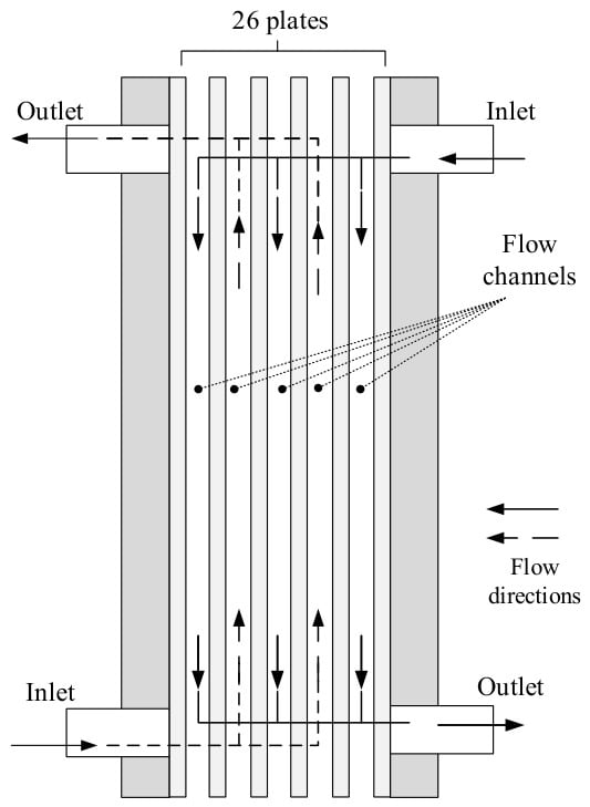
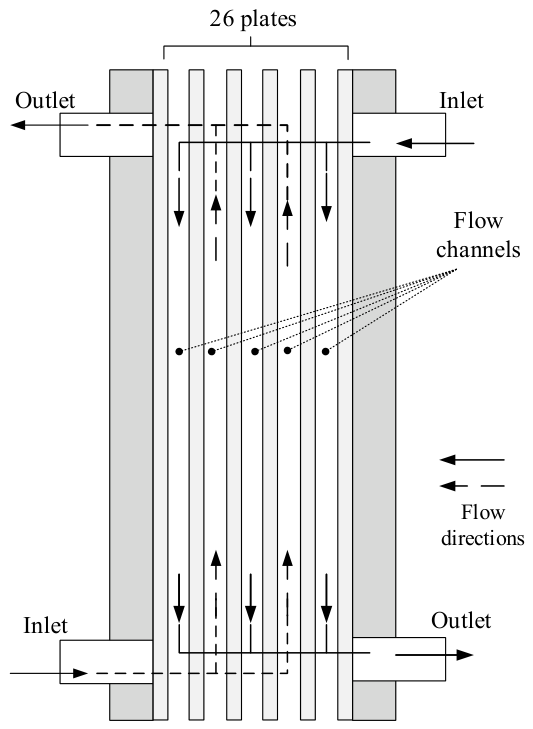
The PHEs used as the test sections are shown in Figure 2. The two test sections, referred to as test section-1 and test section-2, consisted of front and rear frames made of SUS304 (380 mm in height, 140 mm in width, and 15 mm in thickness), test plates made of A5052 aluminum (Figure 3), and gaskets. Test section-1 was used for the 1-month and 3-month seawater flow tests, whereas test section-2 was used for the 6-month and 12-month tests.
Figure 3.
Configuration of the flow channels and seawater directions in the PHE.
As shown in Figure 1, each test section is supplied with DSW branched from a common DSW source, and therefore no differences in water quality or temperature arise between the test sections. Variations in flow rate and water temperature, on the other hand, are described in Section 2.4.
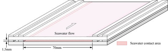
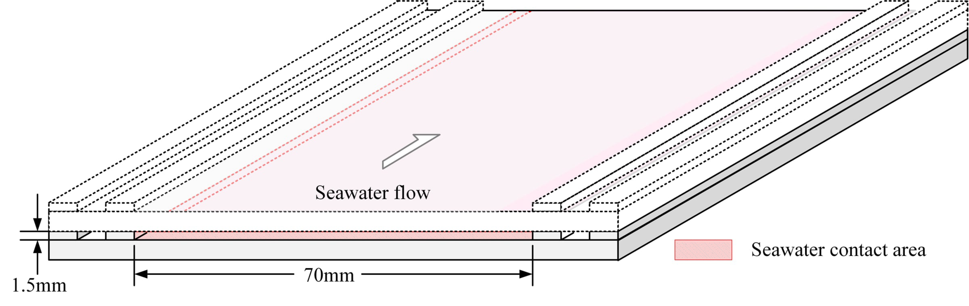
Figure 3 shows the configuration of the PHE. A single flow channel was formed using a pair of specimen plates. Seawater entered from the respective inlets and flowed alternately in opposite directions through each channel. Figure 4 shows a cross-sectional view of the flow channel along the flow direction. Seawater flowed through a channel formed between two specimen plates, with a cross-section 70 mm in width and 1.5 mm in height, coming into contact with the hatched area.
Figure 4.
Cross-sectional structure of flow channel between two test specimens.
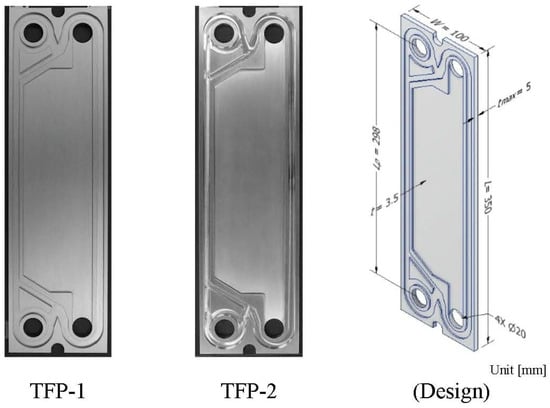
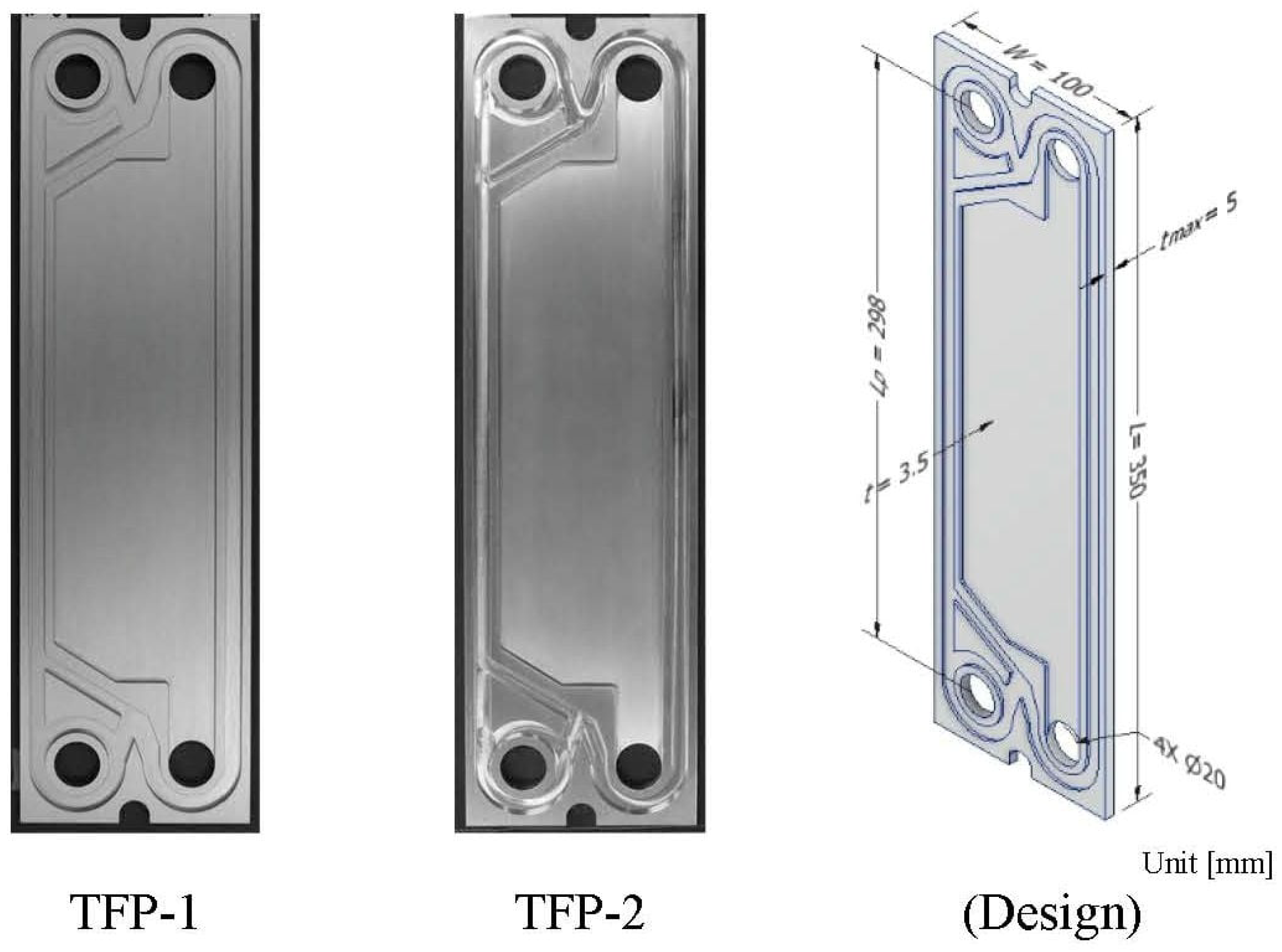
Figure 5 shows the flat test plates. The test plates were made of A5052 aluminum and were 350 mm in height, 100 mm in width, and 3.5 mm in thickness as shown in Table 2. The chemical composition of A5052 used in this study is summarized in Table 3.
Figure 5.
Photographs and designs of the test specimens.
Table 2.
Design of test specimens and flow channels.
Table 3.
Chemical composition of A5052.
Two types of test plates with different surface treatments were used: anodized treated (TFP-1) and untreated (TFP-2). The anodized process was performed in accordance with the surface treatment standards outlined in JIS H8601 [25], resulting in an anodized layer thickness of approximately 20 to 25 µm. The anodizing treatment was also carried out by a specialized manufacturer under the following conditions [26]: current density, 0.6–1.5 A/dm2; voltage, 12–18 V; electrolyte composition, H2SO4 at 13–17 W/V%; duration, 30–45 min; temperature, 19–23 °C. Oxidation was performed using the sulfuric acid method, and post-treatment was performed with boiling water sealing. The initial surface roughness (Ra) was 0.290 μm for the anodized specimens and 0.503 μm for the non-anodized specimens. Two test sections (Test section-1, Test section-2) were prepared. Each test section contained a total of 26 plates, consisting of four anodized A5052 specimens, four non-anodized A5052 specimens, and 18 additional plates used for another experiment [24]. Test section-1 was used for the 1-month and 3-month tests, whereas test section-2 was used for the 6-month and 12-month tests.
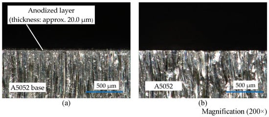
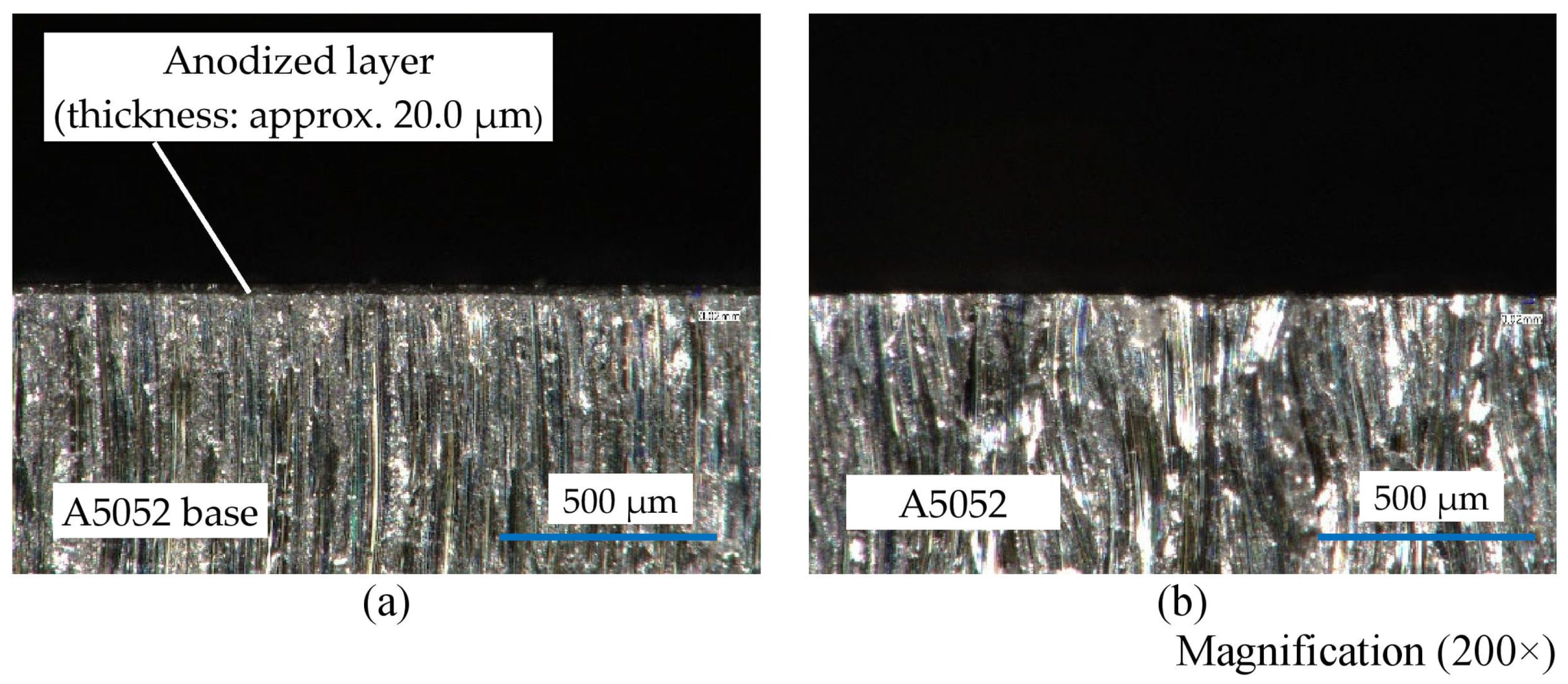
Figure 6 shows the photographs of the cross-sectional structures of the test specimens obtained using a digital microscope. TFP-1 had an anodized layer of thickness approximately 20 μm on the surface of the base A5052 as shown in Figure 6a. In addition, TFP-2 showed only A5052, as shown in Figure 6b.
Figure 6.
Cross-sectional microstructure of the specimens. (a) TFP-1. (b) TFP-2.
2.3. Pre-Processing
The test plates removed from the test section underwent the following pre-treatment steps before analysis:
The specimens were cleaned using an approximately 2 wt% sodium hydrogen carbonate solution at room temperature for approximately 30 min. A soft brush was used to clean the entire specimen surface, with additional brushing applied to areas where deposits adhered strongly. After cleaning, the specimens were air-dried indoors for 24 h prior to weighing.
It should be noted that the influence of the cleaning procedure on specimen mass was not independently evaluated using unexposed control specimens or repeated cleaning-weighing tests. Therefore, the measured mass loss may include uncertainties associated with the removal of corrosion products, seawater deposits, anodized-layer material, and/or substrate material. In addition, for anodized specimens, the measured mass loss may include contributions from both the anodized layer and the aluminum substrate. Consequently, the equivalent thickness-loss values calculated using the density of A5052 should be considered approximate.
2.4. Experimental Conditions
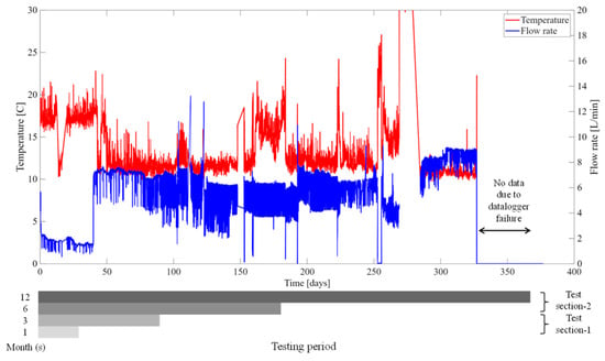
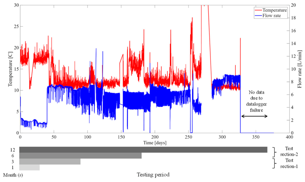
The experimental conditions of this study are as follows: The DSW flow rates ranged from approximately 2.7 to 8 L/min (2.5 to 7.4 cm/s) and were not constant. The reported DSW flow rate represents the flow supplied to an individual test section. Two test sections were operated simultaneously under identical flow-rate conditions, and the same DSW flow rate was supplied to each section. The flow velocity was calculated by dividing the flow rate by the total cross-sectional area of all flow channels within a test section. The seawater flow rate in the 100 kW OTEC demonstration facility on Kumejima Island is approximately 300 t/h (5000 L/min), whereas the flow rate used in the present study was approximately 1/2000 of this value. Under these operating conditions, the flow velocity in the heat exchanger of the OTEC demonstration facility is approximately 20 cm/s. Therefore, the flow velocity used in the present study corresponds to approximately one-eighth of that in the OTEC heat exchanger. The DSW was supplied by the Okinawa Prefectural Ocean Deep Water Research Center. The DSW supply facility operated the pump intermittently, resulting in periodic fluctuations in the flow rate. In addition, the DSW temperature varied seasonally. The inlet temperatures of the test sections were approximately 12.7–16.9 °C. The average temperatures for each exposure period (0–1 month: 16.9 °C, 1–3 months: 13.1 °C, 3–6 months: 12.7 °C, and 6–12 months: 13.8 °C). Because the DSW was supplied from the discharge line of the OTEC condenser system, the DSW temperature varied with operating and environmental conditions and could not be directly controlled in the present experiment.
Each test plate was removed for analysis at 1, 3, 6, and 12 months. The pH, salinity, and dissolved oxygen concentration were not measured directly during the present experiment. Therefore, values reported in previous studies that analyzed the seawater used at the experimental site were adopted: pH 8.0, salinity 3.45% [27], and dissolved oxygen 3.0 mL/L [28].
Owing to the limited number of specimens that could be accommodated in a single test section, all specimens were distributed between two test sections. In Section 1, twelve plates were removed after one month of exposure (four plates for the present study and eight plates for other experiments), and the remaining 14 plates were exposed until the three-month sampling period. Similarly, in Section 2, 12 plates were removed after six months of exposure, and the remaining 14 plates were exposed until the twelve-month sampling period. Since DSW was supplied simultaneously to both test sections, the two sections were operated under identical flow rate conditions.
The specimen identification number, surface treatment, channel position, and exposure start and end dates for each specimen are summarized in Table 4.
Table 4.
Exposure history of the specimens.
Figure 7 shows the temporal variation in the DSW flow rate and temperature. The immersion durations for each specimen are also indicated in Figure 7. Although both test sections were operated under the same DSW supply conditions, the exposure histories of the specimens differed because they were removed at different sampling intervals. Consequently, the specimens were not exposed to completely identical environmental conditions throughout the entire test period.
Figure 7.
Time variation in temperature and flow rate.
3. Result and Discussion
3.1. Mass Reductions in Test Plate
To confirm the average corrosion rate during the exposure period of each specimen, their masses at 1, 3, 6, and 12 months were compared with their initial masses before testing. Mass measurements were performed using an electronic balance with a measurement accuracy of 0.015 g. Each sample was measured three times, and each specimen was weighed three times; the maximum standard deviation of the repeated measurements was 0.012 g. The corrosion rate, Vc [mm/y], was determined based on the measured mass changes as follows:
where mA [g] is the mass after seawater flow, mB [g] is the mass of the specimen before continuous water flow, S [mm2] is the surface area of the specimen, ρ [g/mm3] is the specimen density, and M [months] represents the measurement period in months. The projected dimensions of the plate were 350 mm × 100 mm, while the total surface area S increased to 76,890 mm2 owing to the side surfaces and the gasket-groove geometry. This value includes both sides of the plate, the side surfaces, and the additional surface area associated with the gasket grooves on the corrugated plate surface.
Table 5 presents the original mass, mass loss, and corrosion rate Vc at 1, 3, 6, and 12 months for TFP-1 and TFP-2. As shown in Table 5, the mass loss increased with seawater flow time for all samples. Between 1 and 6 months, the mass loss for both specimens remained within the same order of magnitude. However, at the 12-month measurement point, the value for TFP-2 was approximately four times higher than that of TFP-1. When comparing the corrosion rates by measurement month, TFP-1 exhibited higher corrosion rates in the 1- and 3-month results, which decreased to half the values at 6 and 12 months. In contrast, although the corrosion rate of TFP-2 decreased after six months, it showed an overall increasing trend throughout the entire measurement period. Note that, from 3 to 6 months, both specimens showed mass losses of similar magnitude. However, as described later in Section 3.2, surface observations indicated that corrosion progressed more prominently in TFP-2. This suggests that TFP-2 should exhibit a larger mass loss than TFP-1; however, the influence of corrosion on mass change is discussed in Section 3.3. The corrosion rate of TFP-2 after 12 months was compared with the value reported for untreated A1050 on a herringbone plate in the author’s previous study [24]. While the corrosion rate of untreated A1050 reported in a previous study reached 3.07 × 10⁻² mm/y, the maximum corrosion rate of A5052 observed in the present study was 2.56 × 10⁻² mm/y, approximately 17% lower. Although this comparison suggests that A5052 may exhibit improved corrosion resistance relative to pure aluminum, the specimen geometry and exposure conditions differed between the studies. Therefore, a direct comparison should be interpreted with caution. On the other hand, in the study by Darby [4] on the corrosion loss of A5052 seawater pipes, a corrosion rate of approximately 1.0 × 10⁻² mm/y was observed after 12 months, which is approximately half the value determined in this study. Although the flow conditions of seawater differed between Darby’s experiment and the present study, both results indicate a consistent corrosion rate on the order of 10 μm/y. In contrast, the corrosion experiment on an A5052 CSW intake pipe conducted by Panchal et al. [6] reported a corrosion rate of 3.5 × 10⁻³ mm/y, which is approximately 1/8 of the rate observed in this study.
Table 5.
Corrosion rates of test specimens at each month of measurement.
3.2. Surface Conditions
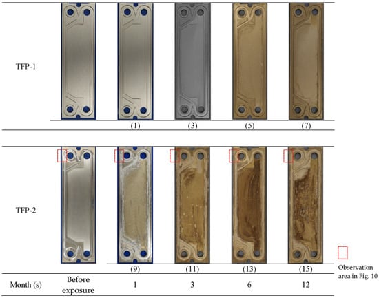
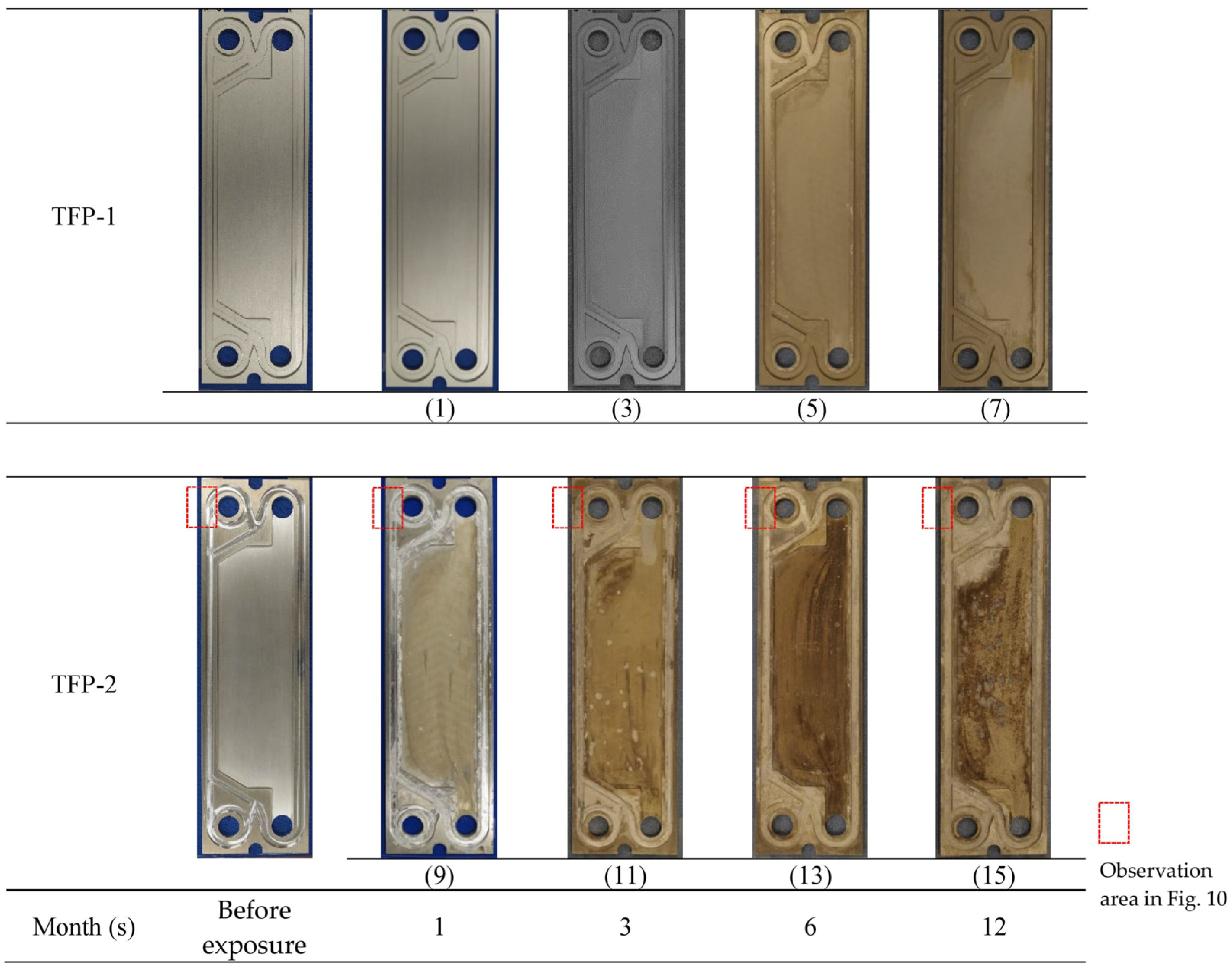
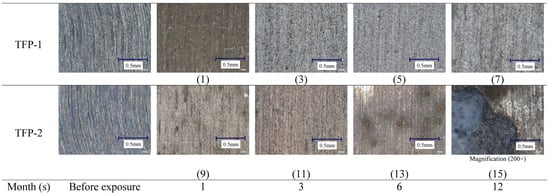
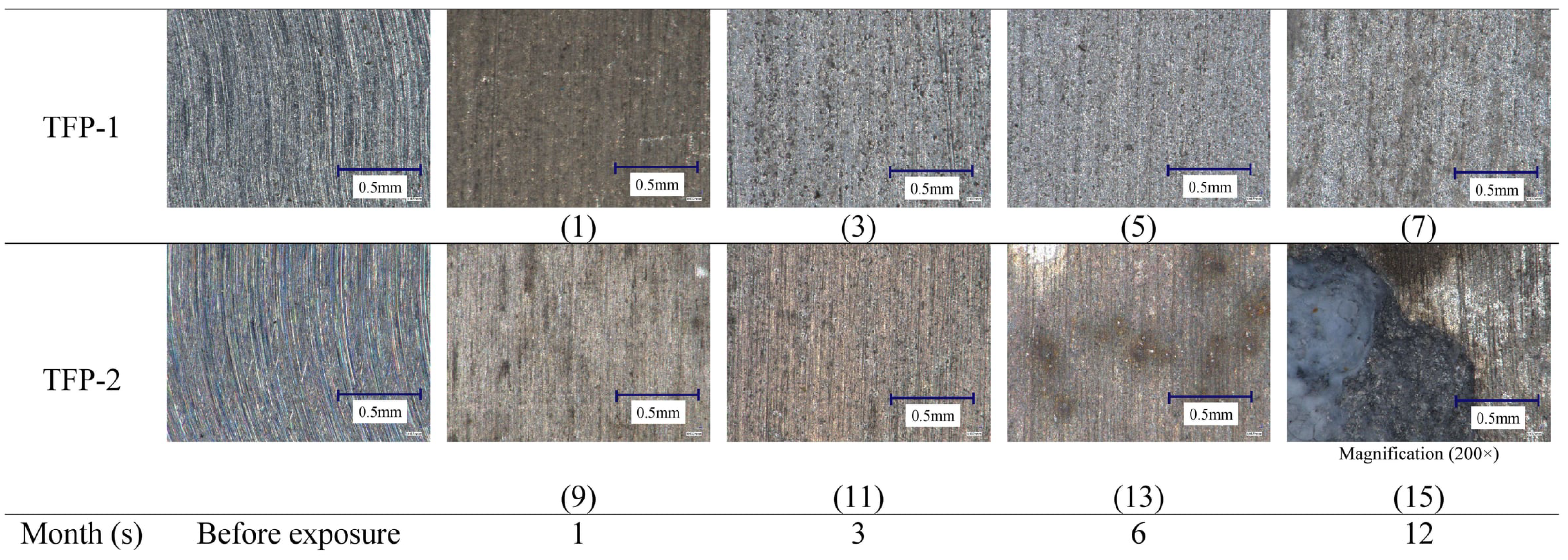
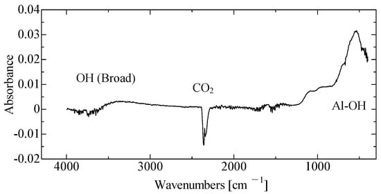
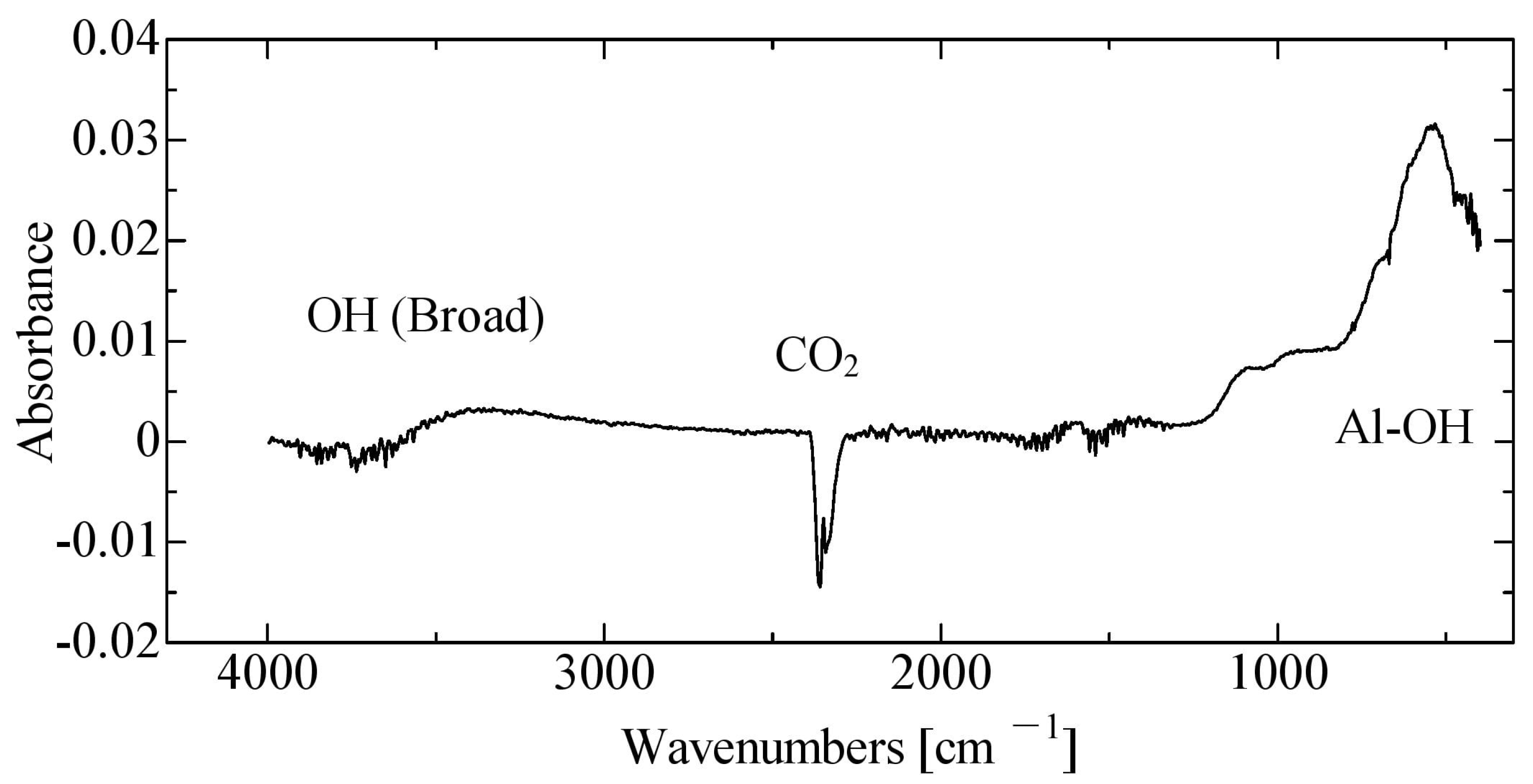
To confirm the changes in the surface conditions of the test plates owing to corrosion, comparative observations were made using digital still camera photography and a digital microscope. Photographs of the test plates captured at different months are shown in Figure 8 and Figure 9. For TFP-1 in Figure 9, the observation was conducted at 200× magnification near the center of a surface depression located in the central region of the specimen. For TFP-2, corrosion was observed at multiple locations on the specimen surface; therefore, a region exhibiting relatively pronounced corrosion was selected for observation at 200× magnification. No noticeable changes in the surface condition of TFP-1 were observed throughout the test period. In addition, no apparent corrosion was detected on the surface of TFP-1, as shown in Figure 8(1)–(7) and Figure 9(1)–(7). In contrast, TFP-2 plates exhibited noticeable changes. White deposits were observed along the gasket grooves on every specimen. The white deposits were analyzed using FTIR, and the resulting spectrum is shown in Figure 10. As shown in Figure 8, characteristic features include a peak at approximately 520 cm−1, a peak near 2350 cm−1, and a broad absorption band in the range of 3200–3500 cm−1. The peak around 520 cm−1 is attributed to Al-OH vibrations, while the broad absorption band at 3200–3500 cm−1 corresponds to hydroxyl (OH) groups. The peak near 2350 cm−1 is associated with CO2 absorption. Based on these characteristic absorption bands, the white deposits were identified as Al(OH)3.
Figure 8.
Photographs of surface images of test specimens at each month.
Figure 9.
Photographs of enlarged surface images of test specimens by digital microscope at each month.
Figure 10.
FTIR spectrum of the corrosion products.
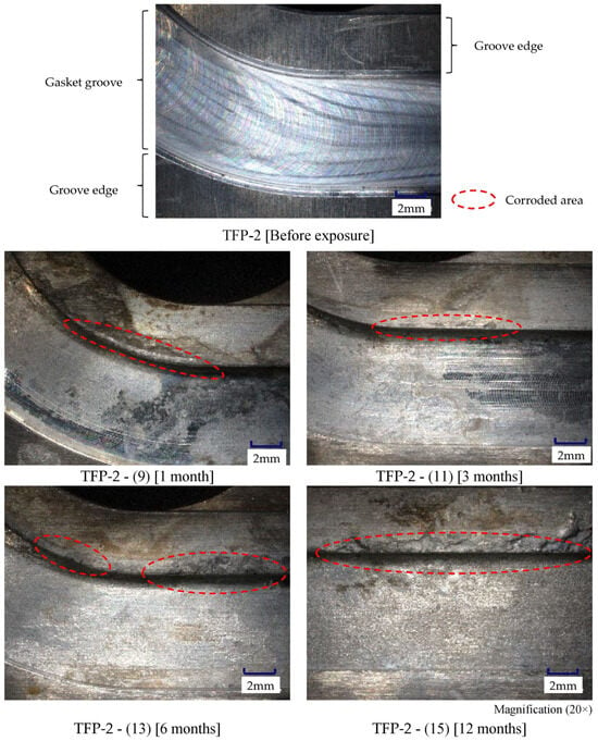
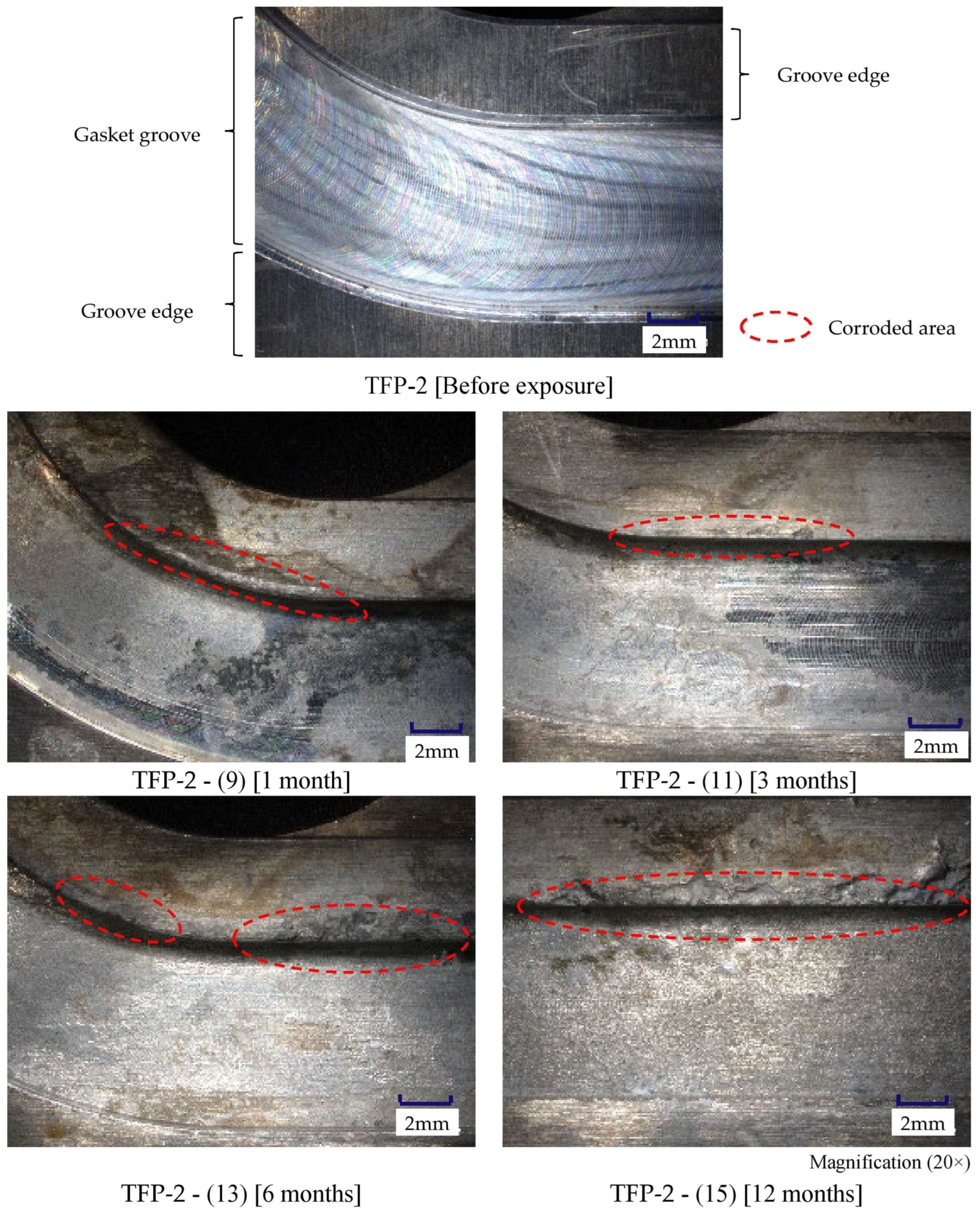
Along the gasket groove, localized and continuous corrosion was observed. An image illustrating this condition is shown in Figure 11. The observation region shown in Figure 11 corresponds to the area enclosed by the red dashed line in Figure 8. Surface discoloration and pit-like localized corrosion were also observed in each interval, as shown in Figure 8(9)–(15). The observed localized attack is considered to be crevice corrosion caused by stagnant seawater trapped between the gasket and the aluminum surface. This interpretation is consistent with the findings of Makai Ocean Engineering [10], which reported severe crevice corrosion in DSW environments. Test plates without surface treatment (TFP-2) were strongly affected by seawater. Furthermore, owing to the structural tendency of the grooves to retain seawater, corrosion progressed and deposits were formed. In contrast, significant corrosion was observed for the surface shown in Figure 9(15). A white, translucent deposit was observed on the surface of the corroded aluminum alloy, which differed from the aluminum hydroxide found in the grooves shown in Figure 8. Preliminary elemental analysis using laser-induced breakdown spectroscopy revealed that this substance is an organic compound.
Figure 11.
Photographs of corrosion along the gasket grooves of TFP-2 by digital microscope at each month.
3.3. Chemical Analysis of the Surface Condition
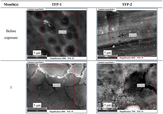
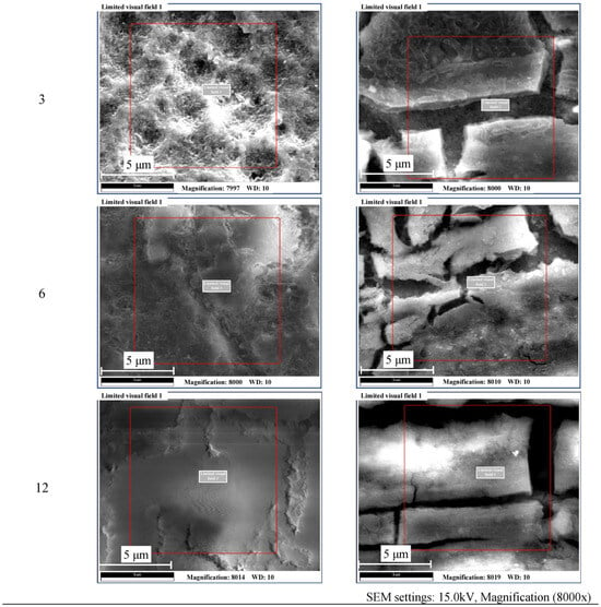
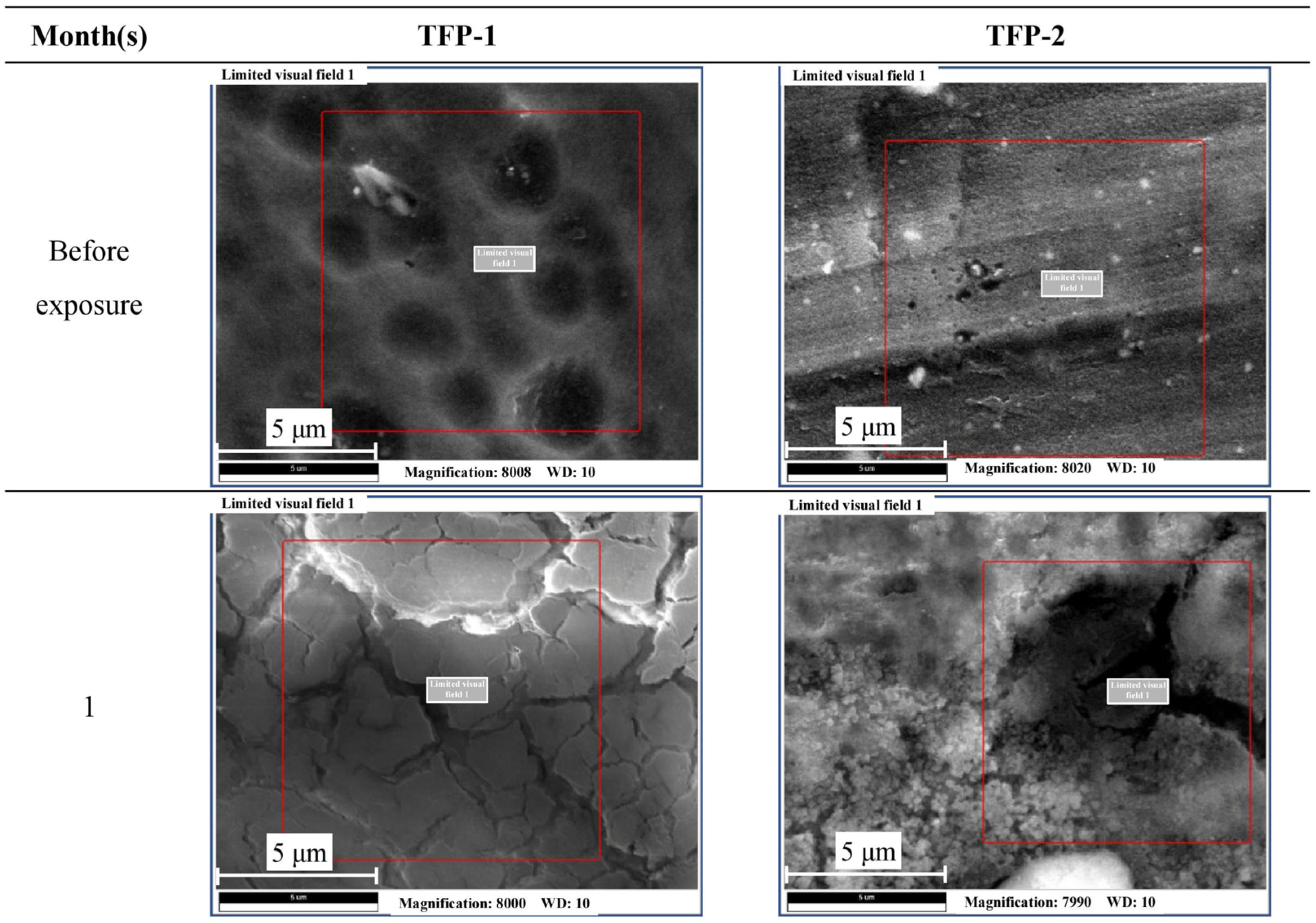
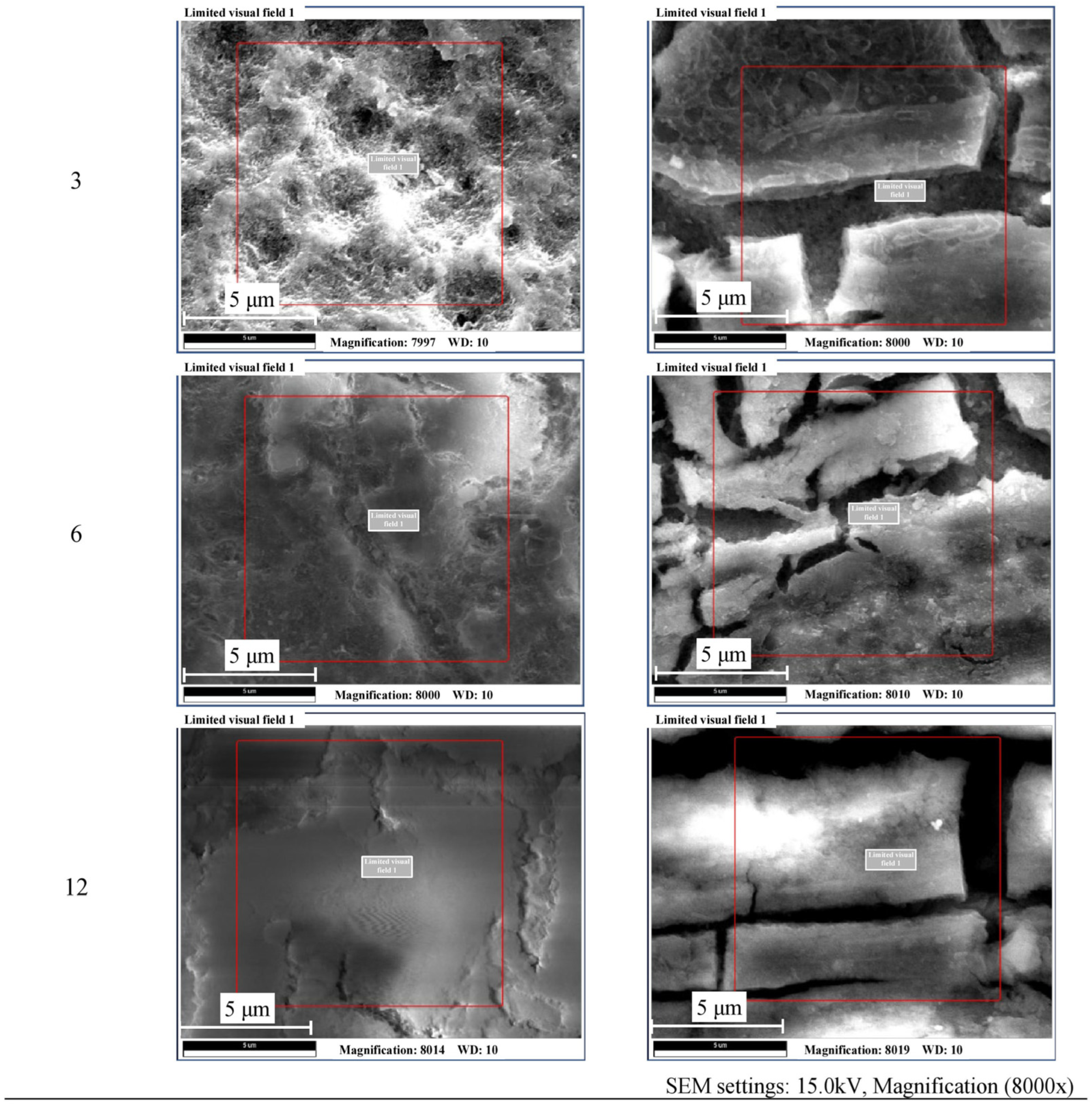
To confirm the surface condition of the test plates, the test plates were analyzed using SEM/EDX. Figure 12 shows the SEM images, and Table 6 shows the results of the compositional analysis by EDX. The test piece used for the SEM observations shown in Figure 12 was cut from a flat surface region adjacent to the edge of the gasket groove. SEM/EDX analysis was performed as follows. After the seawater circulation test, the test plates were cut into specimens approximately 1 cm × 5 cm in size using a wire cutter. The specimens were then mounted on SEM stubs using conductive carbon tape. For the anodized specimens, osmium coating was applied using a sputter coater prior to observation. SEM/EDX measurements were conducted at one representative location on each specimen. The elemental composition was automatically quantified from the acquired EDX spectra using the APEX™ 2.0 (Version 2.0) EDS/EBSD software package (EDAX Inc., Mahwah, NJ, USA). The red frame in the SEM image represents the EDX measurement area.
Figure 12.
SEM images of the specimen surface.
Table 6.
Mass distribution of elements analyzed by EDX (APEX™ EDS, EBSD software, Vsersion 2.0, EDAX Inc., Mahwah, NJ, USA).
The SEM image of TFP-1 reveals a surface with multiple depressions, as shown in Figure 12. These depressions were considered to have formed as a result of the sealing treatment during anodization.
In contrast, the TFP-2 surface shown in Figure 12 exhibits a crystalline layer containing numerous cracks. Diderot et al. [29] conducted a detailed investigation on the formation of biomineralized films in seawater for A5083, an Al–Mg alloy similar to A5052. Their study reported the formation of a film containing cracks caused by drying shrinkage on the aluminum surface, and EDX analysis detected O, Mg, Si, and Ca. Similarly, in TFP-2 shown in Figure 12, a cracked film was observed, and the EDX results in Table 6 were consistent with the findings of Diderot et al. [29]. Similarly, laser-induced breakdown spectroscopy (LIBS) analysis detected organic constituents on the surface of TFP-2 (C: 50.3%, O: 41.7%, and H: 8.0%). Together with the cracked morphology and elemental composition, these observations are consistent with the characteristics of deposits reported by Diderot et al. [29]. However, the biological origin and formation mechanism of the observed layer were not directly investigated in the present study. Therefore, the possibility of biomineralization is discussed as a potential explanation rather than a confirmed mechanism. In conclusion, for TFP-1, only the elements originating from the composition of the test plate and anodized aluminum were detected, and no corrosion products were observed. In contrast, for TFP-2, the passive oxide film was thin, and the seawater environment with a pH of around 8 facilitated the dissolution of Al3+, making corrosion more likely. At the same time, co-precipitation of Mg2+, Ca2+, and SiO2, similar to that reported by Diderot et al. [29], may have occurred on the specimen surface. However, the involvement of microorganisms and the protective function of the deposited layer were not directly evaluated in the present study. Consequently, significant mass loss due to corrosion was not observed, except in the 12-month specimen. However, the role of the deposited layer in suppressing corrosion could not be conclusively determined from the present results.
4. Conclusions
To determine the effect of surface treatment on A5052 aluminum alloy in seawater, a one-year seawater flow experiment was performed. The test plates were anodized A5052 and untreated A5052 aluminum alloy.
- (1)
- The anodized A5052 aluminum alloy exhibited no surface changes after one year of seawater flow using digital still camera and SEM observations. In addition, there was no significant mass loss associated with corrosion, except for the 12-month specimen.
- (2)
- For the 12-month anodized aluminum specimen, a significant decrease in mass was observed. However, the mechanism responsible for this mass loss could not be clarified based on the data obtained in the present study.
- (3)
- On the untreated A5052 surface, the attachment of a white powdery compound identified as Al(OH)3 was observed, indicating that corrosion occurred through anodic dissolution of aluminum from the surface.
- (4)
- For the untreated A5052, surface discoloration and pit-like localized corrosion were observed as early as the first month, and similar surface degradation continued to appear in the subsequent specimens. However, the mass losses of the untreated and anodized specimens were of a similar magnitude during the first six months of exposure. After 12 months, the untreated specimens exhibited substantially greater mass loss than the anodized specimens. Although surface deposits containing Mg, Ca, and Si were observed, their formation mechanism and contribution to corrosion protection could not be determined from the present study.
The results demonstrate that anodizing improves the corrosion resistance of A5052 under long-term deep seawater exposure conditions. However, the relatively large mass loss observed in the 12-month anodized specimen indicates that the long-term degradation behavior of the anodized layer requires further investigation.
From an engineering perspective, anodized A5052 has potential as a lower-cost alternative to titanium for OTEC heat exchanger applications. In addition, our previous work demonstrated improved heat-transfer performance of anodized aluminum in OTEC evaporators [30]. Nevertheless, the present study evaluated only corrosion behavior using a laboratory-scale heat exchanger, and important factors such as heat-transfer performance, pressure loss, leakage resistance, maintainability, and long-term coating stability were not examined.
Several limitations should therefore be recognized. Comparative evaluations with titanium and STS316 were outside the scope of the present study, and quantitative characterization of localized corrosion, such as pit-depth measurements, remaining wall thickness, and cross-sectional analysis, was not performed. Consequently, the resistance of anodized A5052 to perforation cannot be conclusively established. Future studies should include comparative testing with conventional heat exchanger materials, electrochemical measurements, and quantitative evaluations of localized corrosion in order to establish a more comprehensive basis for the application of aluminum alloys to OTEC heat exchangers.
Funding
This research was funded by the Japan Keirin Association Foundation grant number 2023M-324.
Institutional Review Board Statement
Not applicable.
Informed Consent Statement
Not applicable.
Data Availability Statement
The original contributions presented in the study are included in the article; further inquiries can be directed to the corresponding author.
Acknowledgments
The author wishes to thank the Japan Keirin Association Foundation (JKA Foundation:2023M-324) for providing the research funds. The FTIR measurements were conducted at the Analytical Research Center for Experimental Sciences, Saga University.
Conflicts of Interest
The author declares no conflicts of interest. The funders had no role in the design of the study; in the collection, analysis, or interpretation of data; in the writing of the manuscript; or in the decision to publish the results.
References
- Kapranos, P.; Priestner, R. Overview of metallic materials for heat exchangers for ocean thermal energy conversion systems. J. Mater. Sci. 1987, 22, 1141–1149. [Google Scholar] [CrossRef] [Scilit]
- Dexter, S.C. Localized Corrosion of Aluminum Alloys for OTEC Heat Exchangers; ANL/OTEC-BCM-009; Argonne National Laboratory: Lemont, IL, USA, 1979; pp. 1–57. [Google Scholar] [CrossRef] [Scilit]
- Foust, H.D. Brazed Aluminum, Plate-Fin Heat Exchanger for OTEC, Alternative Energy Source III, 4; Hemisphere Publishing: Washington, DC, USA, 1983; pp. 267–276. [Google Scholar]
- Darby, J.B. Ocean thermal energy conversion-materials issues. J. Mater. Energy Syst. 1984, 6, 130–137. [Google Scholar] [CrossRef] [Scilit]
- Larsen-Basse, J. Performance of OTEC heat exchanger materials in tropical seawaters. J. Met. 1985, 37, 24–27. [Google Scholar] [CrossRef] [Scilit]
- Panchal, C.B.; Stevens, H.; Genens, L.; Thomas, A.; Clark, C.; Sasscer, D.; Yaggee, F.; Darby, J.; Larsen-Basse, J.; Liebert, B.; et al. OTEC Biofouling and Corrosion Study at the Natural Energy Laboratory of Hawaii; Argonne National Laboratory Report, ANL/ESD-10; Argonne National Laboratory: Lemont, IL, USA, 1990. [Google Scholar] [CrossRef] [Scilit] [PubMed]
- Fitzpatrick, N.P.; Hron, V.; Hryb, P.J. Aluminum in the marine environment five years of testing at Keahole Point, Hawaii. In Proceedings of the OCEANS 91, Honolulu, HI, USA, 1991; pp. 232–234. [Google Scholar] [CrossRef] [Scilit]
- Hihara, L.H.; Kusada, K. Corrosion of Bare and Coated Al 5052-H3 and Al 6061-T6 in Seawater; Hawaii National Marine Renewable Energy Center (HINMREC): Honolulu, HI, USA, 2011; pp. 1–23.
- Vega, L.A. Ultrasonic Scanning for Corrosion Monitoring; OTEC Heat Exchanger Program: 2016 Ultrasonic Scanning for Corrosion Monitoring Report; Hawaii National Marine Renewable Energy Center (HINMREC): Honolulu, HI, USA, 2016; pp. 1–87.
- Makai Ocean Engineering. Makai Ocean Engineering Annual Report Redacted; Technical Report Prepared for Hawaii Natural Energy Institute; Hawaii Natural Energy Institute: Honolulu, HI, USA, 2020. [Google Scholar]
- Vega, L.A. Ocean Thermal Energy Conversion (OTEC): Economics Update (2023); IEA-OES: Lisbon, Portugal, 2023. [Google Scholar]
- Zhang, D.; Yan, Z.; Gao, L.; Xin, Z.; Zhu, Y.; Wu, W. Corrosion behavior of AA5052 aluminum alloy in the presence of heavy metal ions in 3.5% NaCl solution under negative pressure. Desalination 2024, 570, 117082. [Google Scholar] [CrossRef] [Scilit]
- Peng, C.; Zhang, L.; Fu, Q.; Huang, Y. The effect of low temperature sensitization on the corrosion process of the 5083 Al alloy in artificial seawater. Electrochim. Acta 2025, 544, 147662. [Google Scholar] [CrossRef] [Scilit]
- Ji, Y.; Wu, Y.; Qin, W.; Jin, W.; Hu, W.; Yao, X.; Fan, H.; Xia, D.-H.; Tribollet, B. Improved corrosion resistance of AA5083 after 2 years of exposure in seawater splash and tidal zones: Formation of a protective surface film. Corros. Sci. 2026, 260, 113573. [Google Scholar] [CrossRef] [Scilit]
- Wang, J.; Yang, H.; Du, M.; Hou, J.; Peng, W.; Lin, C. Corrosion mechanism of 5083 aluminum alloy in seawater containing phosphate. J. Ocean Univ. China 2021, 20, 372–382. [Google Scholar] [CrossRef] [Scilit]
- Hagiwara, M. Studies on corrosion of surface-treated aluminum alloys in sea water. J. Jpn. Inst. Light Met. 1969, 19, 136–141. [Google Scholar] [CrossRef] [Scilit]
- Kim, J.-S.; Kang, T.-H.; Kim, I.-K. Surface treatment to improve corrosion resistance of Al plate heat exchangers. Trans. Nonferrous Met. Soc. China 2009, 19, s28–s31. [Google Scholar] [CrossRef] [Scilit]
- Yabuki, A.; Nagayama, Y.; Kanagaki, M. Self-healing Corrosion protective treatment for aluminum in simulated seawater. Bull. Soc. Sea Water Sci. Jpn. 2017, 71, 16–21. (In Japanese) [Google Scholar] [CrossRef] [PubMed]
- Abdeslam, E.A.; Naoual, E.-A.; Omar, D.; Kim, H.; Anvi, B.; Rajesh, H.; Moussa, O.; Mohamed, R.; Khalil, E.M.; Mohamed, E.T.; et al. Novel sulfur epoxy-based protection of aluminum alloy in marine conditions: A combined electrochemical and computational study. J. Mater. Sci. 2025, 60, 13705–13729. [Google Scholar] [CrossRef] [Scilit]
- Deflorian, F.; Rossi, S.; Fedel, M. Aluminium components for marine applications protected against corrosion by organic coating cycles with low environmental impact. Corros. Eng. Sci. Technol. 2011, 46, 237–244. [Google Scholar] [CrossRef] [Scilit]
- Lin, Y.; Yang, S.-C.; Clark, R.; Brown, R. A polyaniline coating material for inhibiting corrosion in marine environment. Mater. Res. Soc. Symp. Proc. 2000, 598, BB5.8.1–BB5.8.5. [Google Scholar] [CrossRef] [Scilit]
- Arima, H.; Inadomi, R.; Matsuda, S. Heat transfer performance of plate heat exchanger for seawater desalination using special coating aluminum alloy plates. Ocean Therm. Energy Convers. 2016, 21, 7–15. Available online: https://www.ioes.saga-u.ac.jp/jp/files/uploads/21-2.pdf (accessed on 30 October 2026). (In Japanese)
- Arima, H. Ammonia corrosion resistance of surface-treated aluminum materials. J. Jpn. Inst. Light Met. 2020, 70, 179–186. (In Japanese) [Google Scholar] [CrossRef] [Scilit]
- Arima, H. Seawater corrosion of the anodized A1050 aluminum plate for heat exchangers. Metals 2025, 15, 300. [Google Scholar] [CrossRef] [Scilit]
- JIS H 8601:1999; Anodic Oxide Coatings on Aluminium and Aluminium Alloys. Japanese Standards Association (JSA): Tokyo, Japan, 1999.
- Ueda Anodizing Industry Co., Ltd. Available online: https://www.uedaalmite.co.jp/textbook/ (accessed on 30 October 2026). (In Japanese)
- Water Quality Test Results of Deep Ocean Water and Surface Water, Okinawa Prefectural Deep Water Research Center. Available online: https://www.pref.okinawa.jp/shigoto/kenkyu/1011194/1022742/1011207.html (accessed on 10 March 2024). (In Japanese)
- Urata, K.; Yasunaga, T.; Ikegami, Y.; Omi, S.; Fukami, K.; Tanaka, T.; Kamano, T.; Ishida, M.; Ohara, J.; Nishida, T.; et al. Oceanic observation and investigation for ocean thermal energy conversion and deep ocean water use in coast of Kemejima island. Deep Ocean Water Res. 2021, 22, 39–47. (In Japanese) [Google Scholar] [CrossRef]
- Diderot, A.; D’elia, M.L.; Bass’eguy, R. Advances in understanding the initial stages of biomineralisation on AlMg 5083 aluminium alloy in a marine environment: Influence of microbial activity and polarisation. Corros. Sci. 2025, 255, 113071. [Google Scholar] [CrossRef] [Scilit]
- Arima, H.; Nishiguchi, M.; Suehiro, S. Effect of the surface form of the herringbone aluminum plate in a plate heat exchanger on the boiling heat transfer performance of ammonia. Appl. Therm. Eng. 2024, 256, 124057. [Google Scholar] [CrossRef] [Scilit]

Disclaimer/Publisher’s Note: The statements, opinions and data contained in all publications are solely those of the individual author(s) and contributor(s) and not of MDPI and/or the editor(s). MDPI and/or the editor(s) disclaim responsibility for any injury to people or property resulting from any ideas, methods, instructions or products referred to in the content. |
© 2026 by the author. Licensee MDPI, Basel, Switzerland. This article is an open access article distributed under the terms and conditions of the Creative Commons Attribution (CC BY) license.