


Abstract
Natural gas hydrate is a promising energy resource. However, the dissociation of hydrates during exploitation poses a significant risk of reservoir instability. A thorough understanding of the mechanical behavior of hydrate-bearing sediments (HBS) during hydrate dissociation is essential for the safe and efficient exploitation of this resource. In this study, we employed the discrete element method to numerically investigate the shear test results of HBS with varying initial hydrate saturations and dissociation ratios. A key innovation of our work is the finding that specimens with higher initial hydrate saturation are more susceptible to the mechanical effects of hydrate dissociation. The microscopic parameters of specimens with different initial hydrate saturations and their corresponding dissociation ratios can be described by a new unified function. Both hydrate saturation and dissociation path significantly affect the mechanical behavior of HBS, and these two factors must be considered simultaneously when constructing relevant constitutive models. This study offers new theoretical insights and provides important reference values for the future development of accurate constitutive models for HBS.
1. Introduction
Natural gas hydrate is a white combustible crystalline solid formed from methane and water under low-temperature and high-pressure conditions [1,2]. It occurs in enormous quantities within submarine sediments and permafrost worldwide, making it a promising alternative energy resource [3]. Currently, most exploitation methods for natural gas hydrate require its in-situ dissociation within the reservoir prior to methane gas recovery [4,5,6]. This process, however, weakens the mechanical reinforcement effect that hydrates exert on the reservoir, leading to a sharp increase in risks such as wellbore instability, uneven reservoir subsidence, and even submarine landslides [7,8]. To ensure the safe and efficient exploitation of natural gas hydrate resources, it is necessary to gain a deep understanding of the degradation patterns and underlying mechanisms by which hydrate dissociation compromises the mechanical strength of hydrate-bearing sediments (HBS).
The presence of hydrates significantly alters the mechanical behavior of sediment grains [9,10,11]. Early triaxial tests of HBS revealed that once hydrates form within the sediment, both its stiffness and strength increase markedly [12,13,14,15,16]. However, this enhancement effect on the mechanical properties of sediments only occurs when the hydrate saturation exceeds a certain threshold, such as 15% [17]. In addition, the shear dilation behavior of HBS becomes more pronounced with increasing hydrate saturation [18]. As research advances, particularly with the development of visualization testing techniques, various contact modes between hydrates and sediments have been identified [19,20]. Pore filling, cementation, and grain coating each play distinct roles during the shearing process. Among these, cementation is the dominant factor altering the mechanical behavior of sediments. Based on this finding, a large number of constitutive models have been developed to predict the mechanical characteristics of HBS under different experimental conditions [21]. Given that factors such as temperature and pressure inherently affect the stability of hydrates, some constitutive models also incorporate multiple influencing factors on the mechanical behavior of HBS [15,22]. In these models, hydrate saturation is typically treated as a fixed value representing an initial condition. Alternatively, some researchers simply adjust the hydrate saturation parameter to simulate the mechanical effects of hydrate dissociation on the sediment [23,24,25]. Such an approach results in a monotonic correlation between hydrate saturation and the mechanical behavior of HBS. However, results from dissociation mechanical tests on HBS show that even a slight dissociation of hydrates leads to a significant reduction in their mechanical properties [26,27]. In other words, even if a substantial amount of undissociated hydrates remains within the sediment, their contribution to enhancing the mechanical strength of the sediment has already diminished considerably.
Since the formation and dissociation of hydrates involve complex heat and mass transfer processes, they are difficult to control precisely during experiments. If hydrates cannot grow uniformly within the sediment, the mechanical properties of HBS are hardly reproducible, even if the hydrate saturation remains constant. Subsequently, the ice seeding method or frost seeding method was developed in an attempt to address this issue [28,29]. However, the problem of achieving uniform hydrate dissociation has still not been satisfactorily resolved. Numerical simulations have already demonstrated that non-uniform hydrate dissociation exerts a significant influence on the mechanical properties of HBS [30,31]. In other words, it is extremely challenging to conduct an in-depth investigation into the mechanical behavior of HBS during hydrate dissociation using conventional experimental approaches.
The discrete element method (DEM) simulates the complex mechanical behaviors of granular materials through various inter-particle contact models. In recent years, this approach has yielded substantial findings in investigating the mechanical properties of HBS [32]. The cementing effect of hydrates on sediment particles can be captured using a parallel-bond model [31,33], while the mechanical behavior of sediment particles themselves can be described via a rolling resistance linear contact model [34,35]. In DEM numerical simulations, both the location and quantity of hydrate formation and dissociation can be precisely controlled. This enables a thorough investigation into how hydrates influence the mechanical characteristics of sediments. For instance, previous researchers have explored the effects of hydrate distribution, content, and dissociation patterns on sediment mechanical properties [31,33,36,37]. Our earlier work also developed a DEM model to simulate the impact of hydrate dissociation on sediment mechanics [33]. Although some mesoscopic mechanisms had been identified, the relevant experimental data at that time were insufficient. This prevented a deep understanding of the underlying mechanism by which hydrate dissociation influences the mechanical behavior of HBS.
In this study, we conducted numerical investigations using the discrete element method (DEM, PFC3D, version 6.00) to examine the mechanical properties of HBS under varying initial hydrate saturations and dissociation ratios. Special emphasis was placed on the cementing effect of hydrates on sediment particles. By analyzing the results of mechanical tests on HBS alongside the evolution of mesoscopic parameters derived from the corresponding DEM models, the mechanical behavior of these sediments under different initial saturations and dissociation ratios was thoroughly examined. Subsequently, by integrating unique DEM-based descriptions of particle-scale behaviors, such as particle displacement and force chain development, the underlying mechanisms through which hydrate dissociation affects sediment mechanical properties were revealed. These findings provide an important theoretical reference for developing accurate predictive models of the mechanical behavior of hydrate-bearing sediments in the future.
2. Materials and Methods
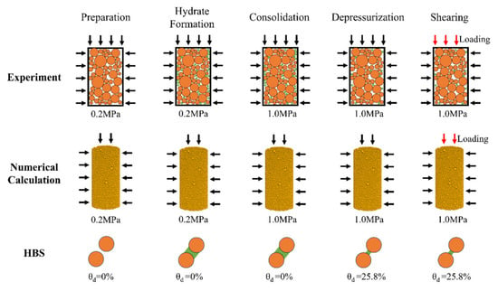
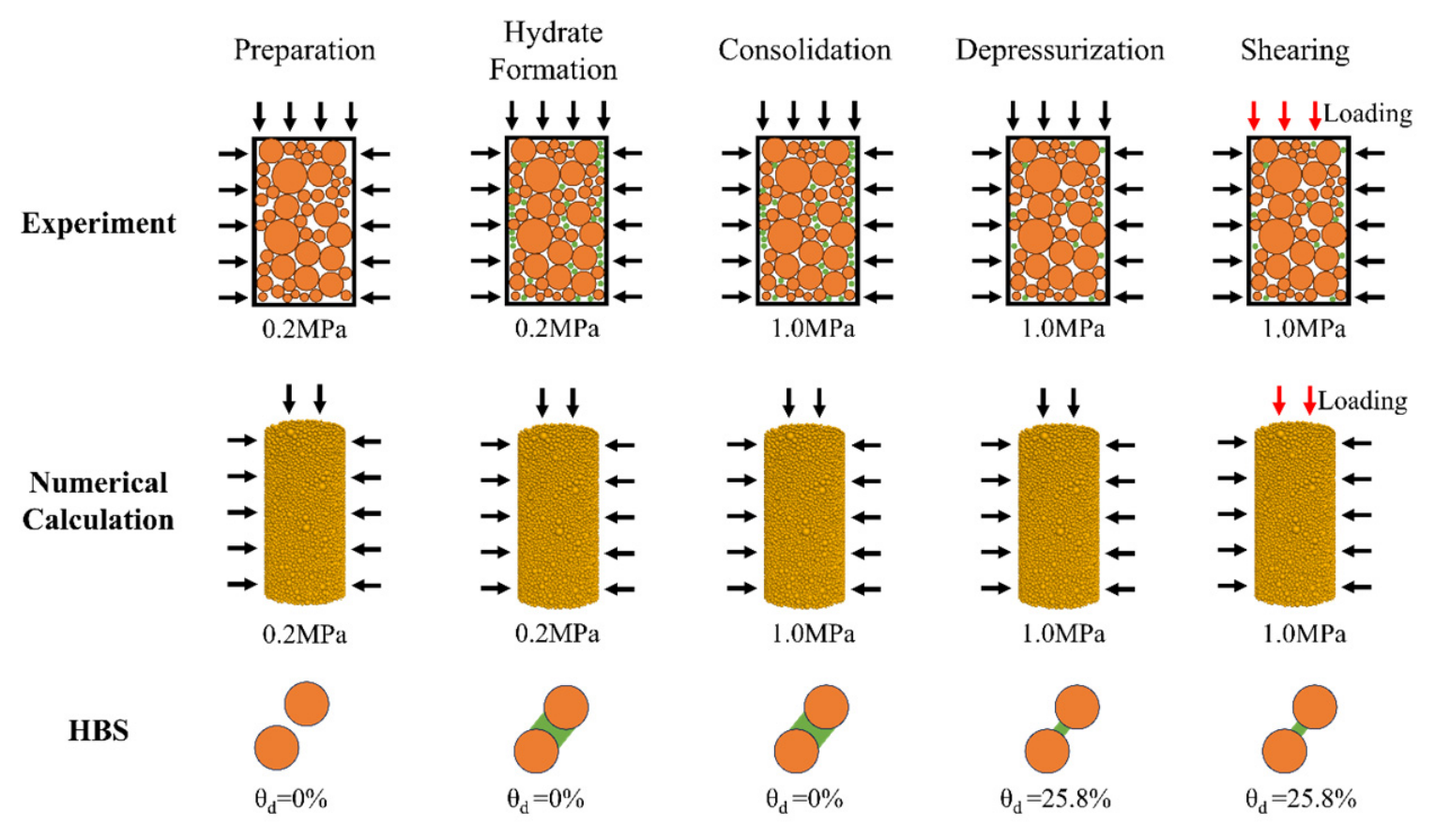
Figure 1 presents a schematic diagram of the experimental procedure and the corresponding process of constructing numerical calculation models. The experiment was conducted using a self-developed integrated testing apparatus (Jiangsu Kedi Scientific Research Instrument Co., Ltd., Hai’an, Jiangsu, China) for the mechanical properties of HBS. The apparatus mainly consists of a pressure chamber, a pressure control system, a temperature control system, and a data acquisition system. The pressure chamber is made of 304 stainless steel, with a maximum bearing capacity of 35.0 MPa, providing a high-pressure environment for hydrate formation. The pressure control system comprises four independently controllable high-precision servo systems, with pressure sensors having a measurement range of 0–30 MPa and an accuracy of 0.1% F.S. These provide confining pressure, pore pressure, axial pressure, and back pressure for the testing apparatus. The temperature control system utilizes a constant-temperature water bath, with an adjustable temperature range of 248.15–323.15 K and an accuracy of ±0.1 K. The methane gas used in the experiments was purchased from Foshan Huate Gas Co., Ltd., Foshan, China, with a purity of 99.9%, and the water used throughout the experiments was laboratory-prepared distilled water.
Figure 1.
A schematic diagram of the experimental procedure and the corresponding process of constructing numerical calculation models (Red arrows and black arrows represent axial stress and effective confining pressure, respectively; yellow particles represent sand, and green particles represent hydrate).
The experimental procedure is briefly described as follows. First, a certain amount of sand was thoroughly mixed with deionized water and then compacted into the mold in layers. After specimen preparation, the confining pressure was increased to 0.2 MPa to ensure stability. Methane gas was subsequently injected into the specimen while maintaining an effective confining pressure of 0.2 MPa until the pore pressure reached 8.0 MPa. The temperature was then lowered to 275.15 K to form hydrates. Thereafter, the effective confining pressure was increased to 1.0 MPa for full consolidation. If hydrate dissociation is not considered, the shear test was performed directly at a rate of 0.12 mm/min. The detailed experimental conditions are summarized in Table 1.
Table 1.
The detailed experimental conditions [28].
In this study, hydrate dissociation was controlled by reducing the pore pressure. When the pore pressure fell below the hydrate phase-equilibrium condition, part of the hydrate dissociated. During this process, the effective confining pressure on the specimen was maintained constant. The hydrate saturation in the specimen was calculated based on the volume of dissociated gas. Once the hydrate saturation reached a predetermined value, the shear test was initiated. Further detailed information can also be found in our previous report [28].
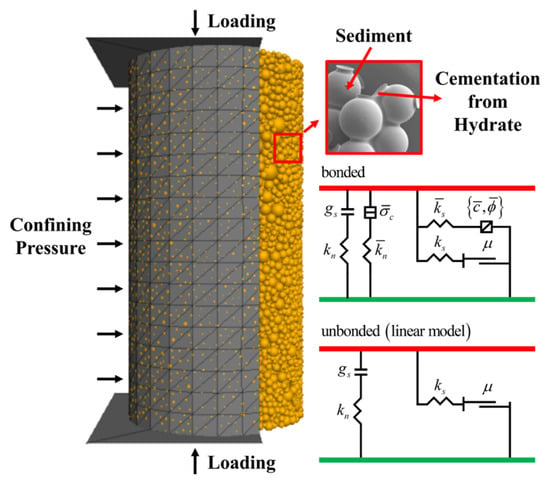
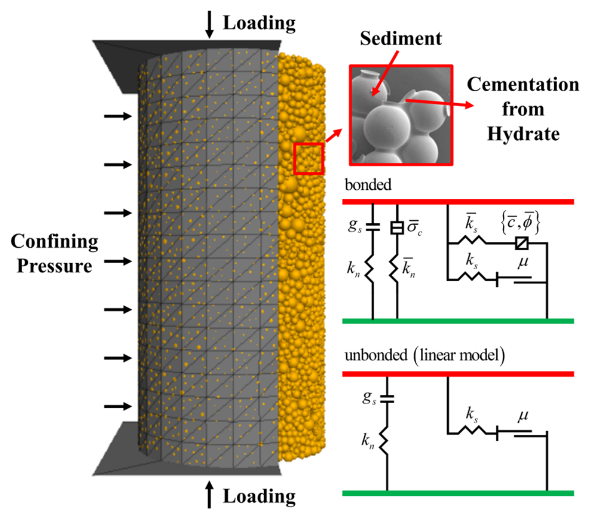
In discrete element modeling, the basic properties of particles, such as particle size distribution and density, are kept consistent with those in the experiment [28]. Similarly, a cylindrical specimen with a diameter of 5 mm and a height of 10 mm was first generated. The model contains a total of 332,479 particles, with a porosity of 0.396 and a median particle diameter of 0.29 mm. For sand particles, the rolling resistance model was adopted for particle contacts. As shown in Figure 2, instead of incorporating solid hydrate particles into the specimen, the contact model between some sand particles was replaced with a parallel bond model. This approach effectively captures the cementing effect of hydrates on sand particles [31,33]. The hydrate saturation is defined by the ratio of the two different contact models. The cementing effect of hydrates takes effect after the pre-consolidation of the specimen. Thereafter, the effective confining pressure was increased to 1.0 MPa. If hydrate dissociation is not considered, the shear test was conducted directly.
Figure 2.
Schematic illustration of the grain contact model.
In the discrete element model, the dissociation rate of hydrates is controlled by adjusting the value of (the parallel-bond radius multiplier) in the model. The advantage of this approach is that it avoids the need to reconsider the non-uniformity of hydrate dissociation. A similar method can be found in previous studies [31]. It should be noted that, to simulate the progressive dissociation of hydrates during the experiment, the value of is also decreased stepwise. Each time is changed, the model must be allowed to reach a new steady state. This treatment ensures that the movement behavior of sediment particles during hydrate dissociation is more realistic. The parameter optimization for DEM model is shown in Appendix A.
The stress–strain results of the host sand were first used for parameter calibration of the DEM model. Once the experimental results agreed with the numerical results, the relevant contact-model parameters for the host sand were retained. Subsequently, parameter calibration for shear tests was performed using HBS specimens. Here, only the stress–strain results of HBS with the lowest hydrate saturation and dissociation ratio were employed for calibration. Results from all other test conditions served as validation.
3. Results and Discussion
3.1. Stress–Strain Curve
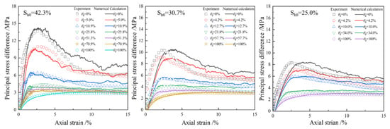
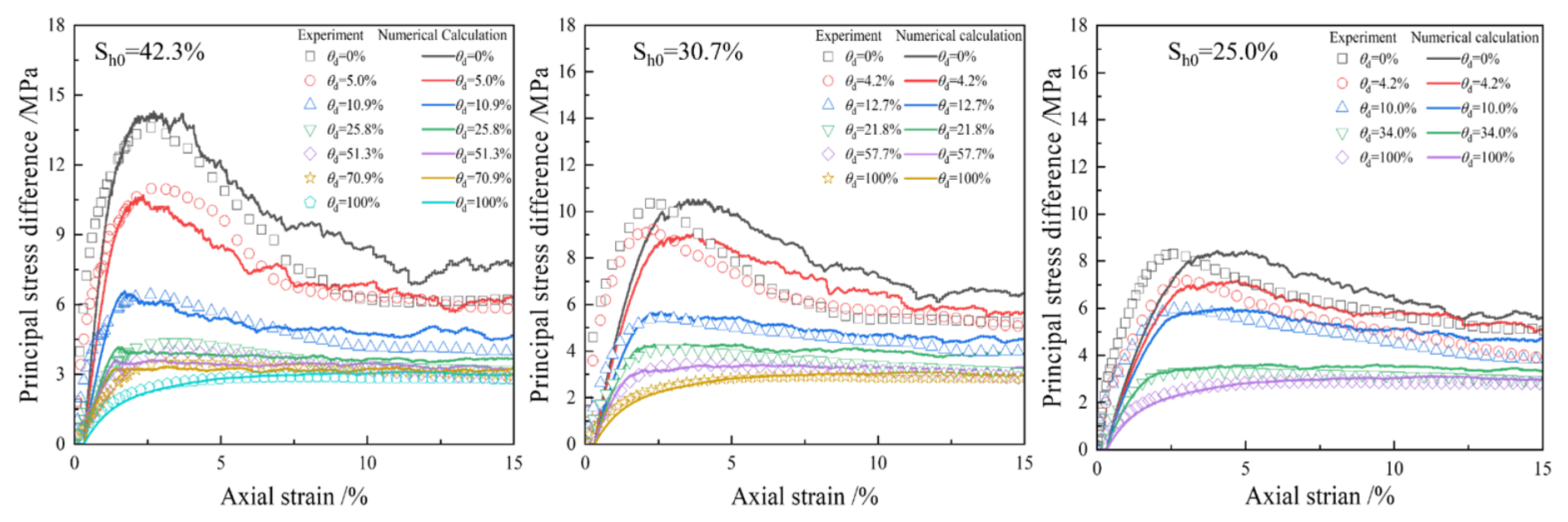
Figure 3 presents the stress–strain curves of HBS under varying initial hydrate saturations and dissociation ratios, as obtained from both experiments and numerical calculations [28]. It can be observed from Figure 3 that the stress–strain characteristics of the sediments under different experimental conditions are well captured and replicated by the numerical calculations. Specimens with higher initial hydrate saturation exhibit a notable increase in both stiffness and peak strength. However, the dissociation of hydrates leads to a marked deterioration in the mechanical strength of the sediments. This degradation becomes even more pronounced for specimens with a higher initial hydrate saturation. Similar findings have also been reported in previous studies [9,33,38].
Figure 3.
The stress–strain curves of HBS under varying initial hydrate saturations and dissociation ratios.
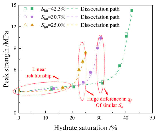
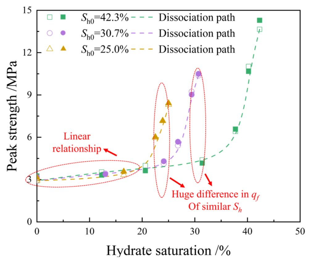
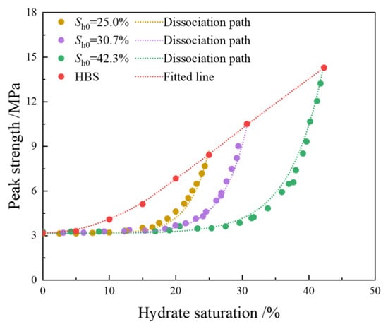
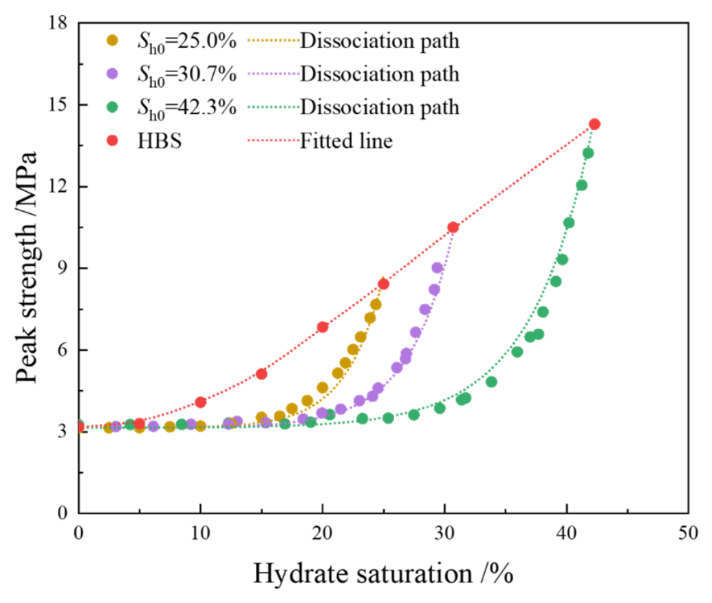
Figure 4 presents the peak strength of HBS under various experimental conditions. Hollow and solid symbols denote experimental and numerical results, respectively. Additionally, the hydrate dissociation paths are delineated by dashed lines in Figure 4. First, the relationship between hydrate dissociation and the degradation of sediment mechanical properties is not linear. During the early stage of hydrate dissociation, the decline in sediment mechanical strength is more pronounced. However, when the hydrate saturation is relatively low (e.g., around 20%), the hydrate saturation and the peak strength of the specimen exhibit an almost linear relationship. By comparing data points along different dissociation paths, it can be observed that at similar hydrate saturations, the peak strengths of the specimens differ significantly. That is, when assessing the mechanical properties of HBS, hydrate saturation alone cannot be directly correlated with their shear strength. The hydrate dissociation path must also be taken into account; otherwise, substantial prediction errors may arise.
Figure 4.
The peak strength of HBS under various experimental conditions.
3.2. Microscopic Parameter Evolution
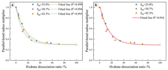
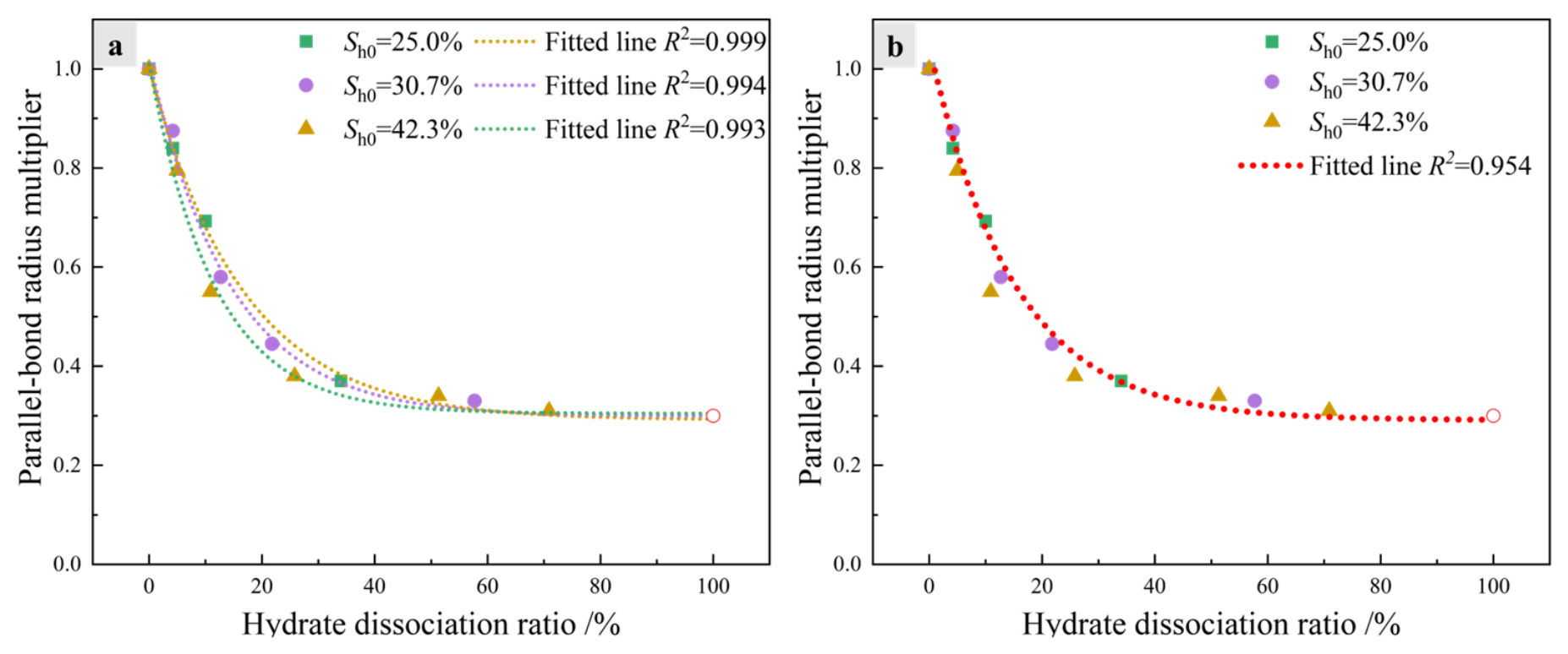
As previously described, the degree of hydrate dissociation in this study is correlated with parameter . Figure 5 illustrates the relationship between the degree of hydrate dissociation and parameter under various experimental conditions. In Figure 5a, the dashed line represents the fitted curve, with the fitting equation given as follows:
where A, B, and C are fitting parameters, whose specific values are listed in Table 2. As shown in Figure 5a, the distribution relationships between and are relatively similar across specimens with different initial hydrate saturations. To simplify the calculation procedure, all data points in Figure 5b are simultaneously fitted using Equation (1), yielding a new fitted curve. In subsequent calculations, this fitted curve will serve as the basis for determining values under different experimental conditions. From these fitted curves, it is evident that during the early stage of hydrate dissociation, the value of decreases rapidly. When the hydrate dissociation ratio approaches approximately 50%, the change in becomes minimal. This observation is consistent with the relationship between the stress–strain behavior of hydrates and the degree of hydrate dissociation shown in Figure 3.
Figure 5.
(a) The evolutionary relationships between the hydrate dissociation rate and microscopic parameters are fitted separately. (b) The evolutionary relationships between the hydrate dissociation rate and microscopic parameters are fitted together.
Table 2.
The fitted line information.
To further investigate the deterioration process of the mechanical properties of HBS during hydrate dissociation, the mechanical behavior of sediments under varying degrees of dissociation was extended based on the fitting results presented in Figure 6. Figure 6 depicts the relationship between the peak strength of HBS and hydrate saturation after this extension. Similarly, the dashed lines represent the dissociation paths of hydrates in specimens with different initial hydrate saturations. It can be observed that the variation pattern of peak strength with hydrate dissociation for specimens with different initial hydrate saturations is analogous to that shown in Figure 4. This implies that time-consuming experimental results can be efficiently obtained using the model developed in this study [28]. Based on the experimental results and preliminary simulation calculations, data regarding the influence of extensive hydrate dissociation on the mechanical behavior of sediments can be obtained through numerical simulations. This makes it possible to interpret in greater detail the mechanisms by which dissociation affects the mechanical properties of sediments.
Figure 6.
The relationship between the peak strength of HBS and hydrate saturation.
3.3. Particle Displacement
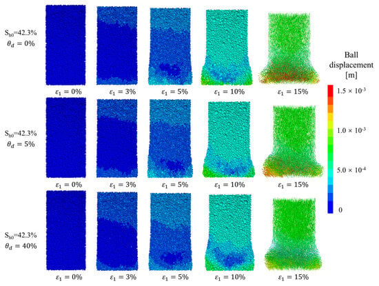
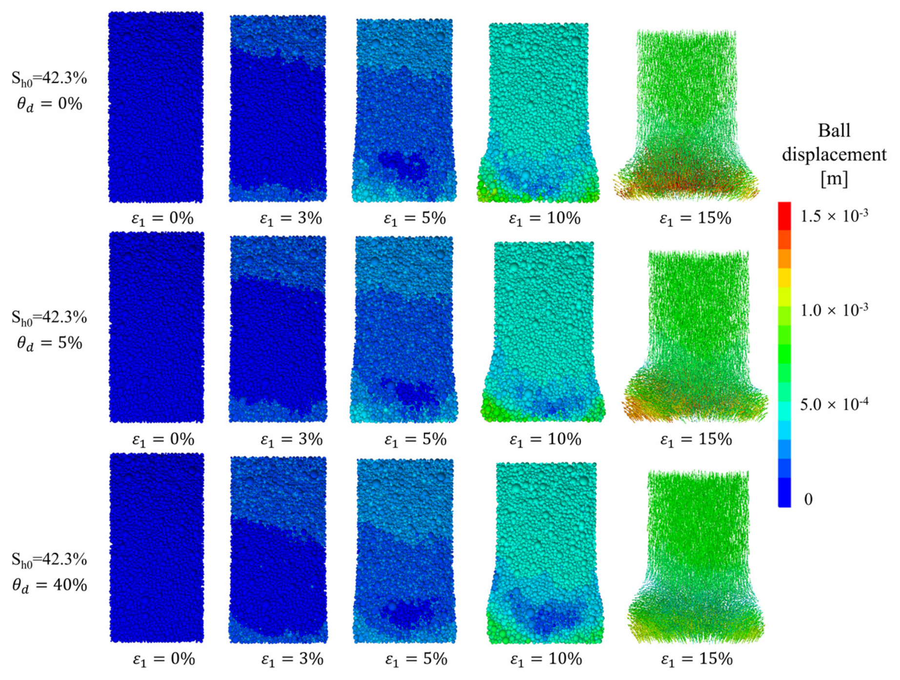
The evolution of particle shear displacement under different hydrate dissociation ratios is illustrated in Figure 7. When no hydrate dissociation occurs, as shearing progresses, the displacement of particles at the bottom of the specimen gradually becomes significant, accompanied by dislocation phenomena. This pronounced particle displacement and dislocation are also the reasons for the formation of shear bands and the relatively high volumetric dilation in the specimen. Even at a hydrate dissociation ratio of only 5%, it can be observed that the extent of particle displacement decreases markedly. However, at the final stage of shearing, notable particle dislocation still persists at the bottom of the specimen. When the hydrate dissociation ratio reaches 40%, the deformation of the specimen has been substantially suppressed. Previous studies have reported that as the hydrate dissociation ratio increases, the volumetric strain of the specimen decreases significantly [9,28,38]. Here, the gradual mitigation of sediment particle migration with increasing hydrate dissociation degree precisely accounts for this phenomenon.
Figure 7.
The evolution of particle shear displacement under different hydrate dissociation ratios.
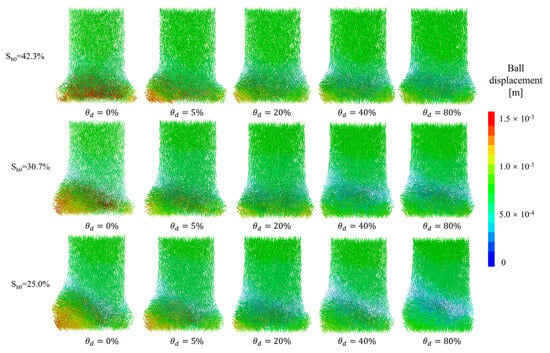
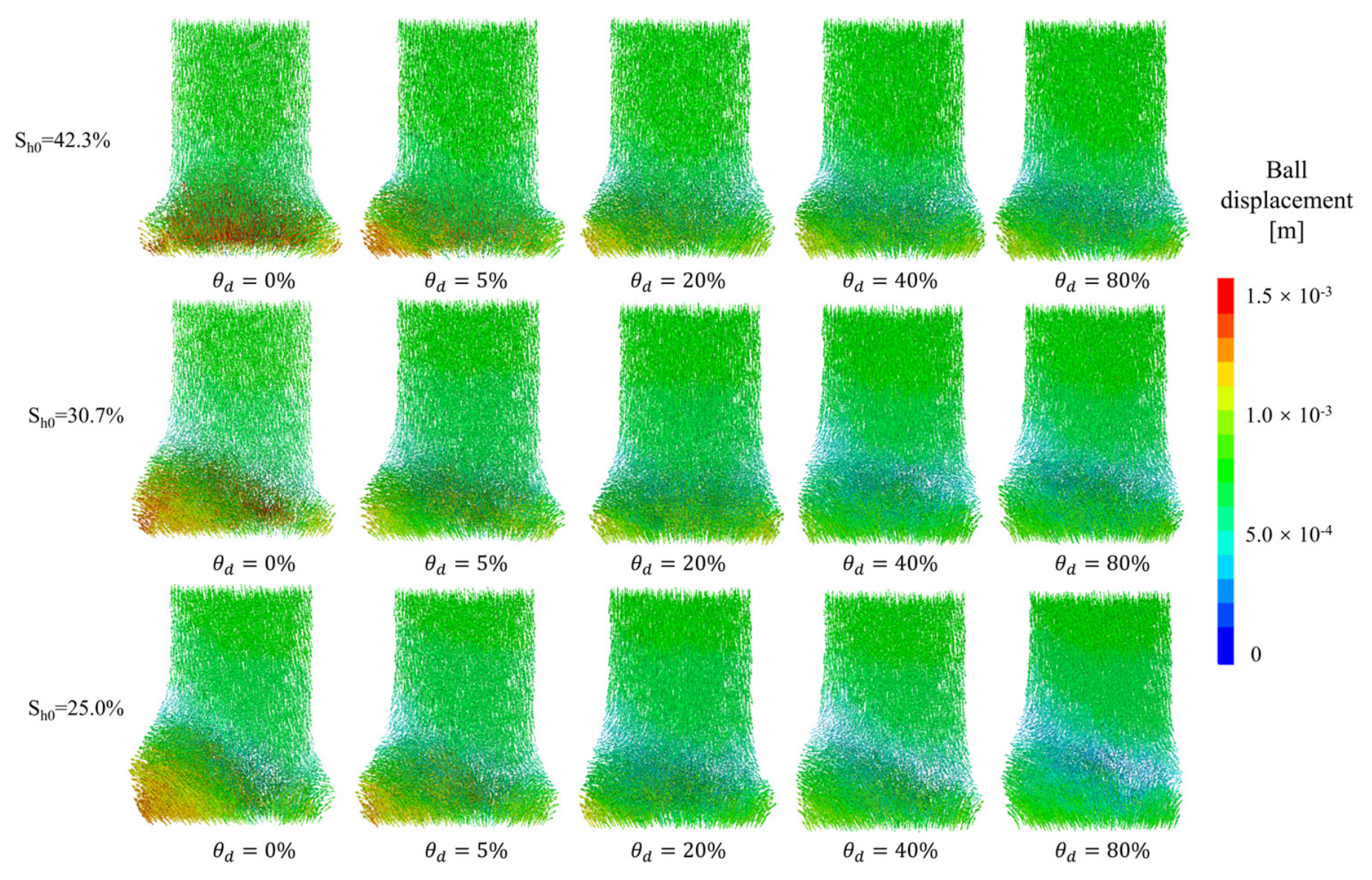
Figure 8 shows the final particle migration patterns of HBS under different initial hydrate saturations and dissociation ratios. First, consider the case without hydrate dissociation. As the hydrate saturation decreases, the intensity of particle displacement diminishes markedly. This is attributed to the cementation effect of hydrates on sediment particles, which restricts their free movement, requiring larger displacements to counteract the increase in axial stress. Furthermore, the initial hydrate saturation exerts a significant influence on the mode of particle displacement. For instance, as the hydrate dissociation ratio increases, the displacement behavior of specimen particles remains qualitatively similar to that of the original HBS, albeit with reduced magnitude. For HBS with different initial hydrate saturations, when the hydrate dissociation ratio is high, their particle displacement behaviors are nevertheless distinctly different. This implies that the movement behavior of particles is governed by the initial distribution of hydrates [35]. Although a large portion of hydrates has dissociated, their initial cementation effect on the particles may lead to structural differences in the particle arrangement. Such an influence persists even after hydrate dissociation. In other words, the strain behavior of a specimen is not solely related to its current hydrate saturation, but is also affected by the history of hydrate formation and dissociation.
Figure 8.
The final particle migration patterns of HBS under different initial hydrate saturations and dissociation ratios.
3.4. Force Chain Evolution
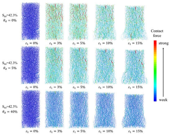
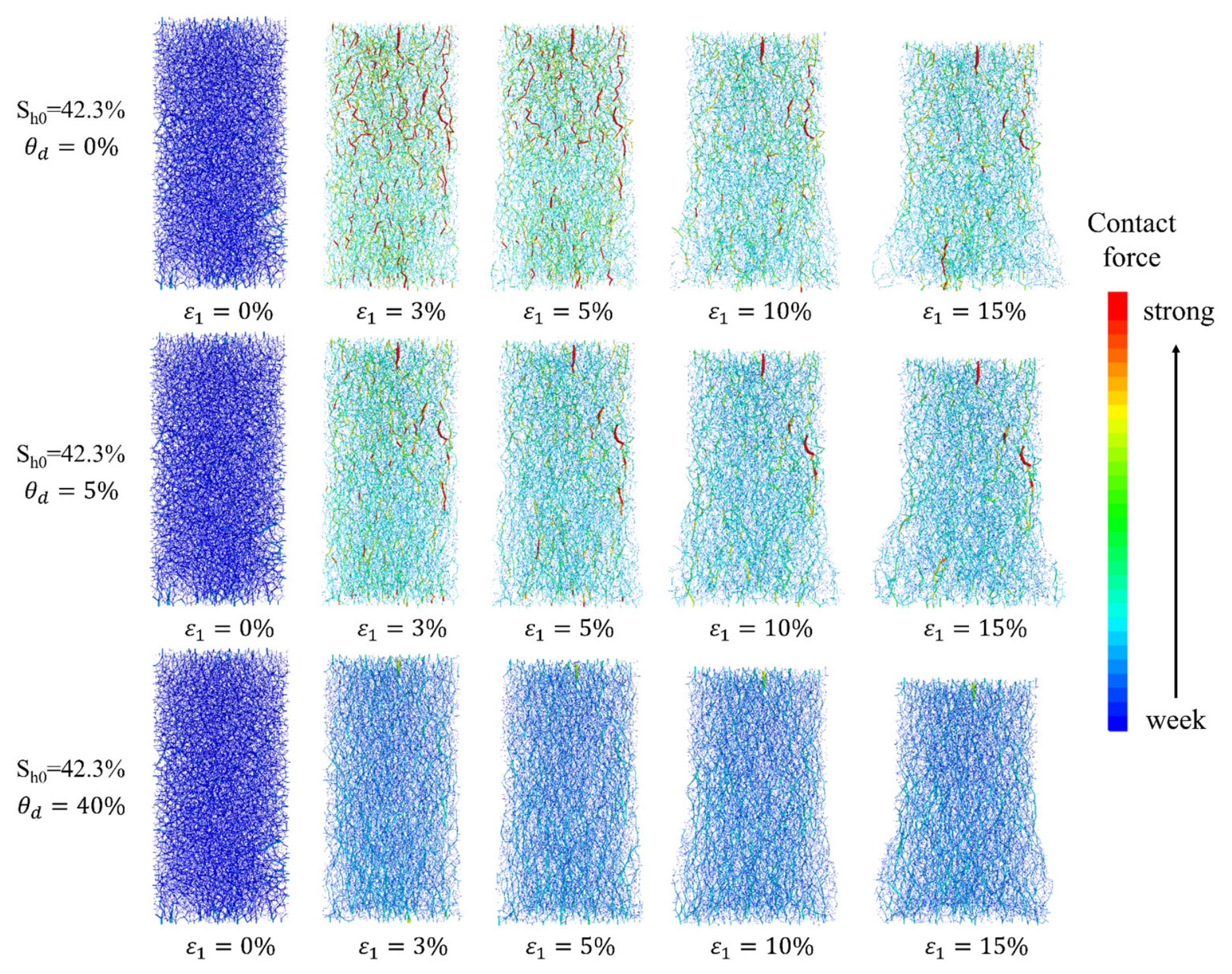
Figure 9 illustrates the evolution of force chains within HBS characterized by a high initial hydrate saturation, subjected to varying hydrate dissociation ratios during shearing. In specimens without hydrate dissociation, the initially dense network of weak force chains is progressively supplanted by strong force chains oriented along the principal stress direction at the early stage of shearing. As shearing continues, these strong force chains gradually weaken and become dispersed; nevertheless, the overall force chain intensity within the specimen remains relatively elevated. For HBS with merely 5% hydrate dissociation, the strong force chains along the principal stress direction have already undergone a marked reduction at the initial shearing stage. This observation aligns consistently with the previously noted phenomenon that even a minor degree of hydrate dissociation can significantly degrade the mechanical strength of the sediment. Consequently, the strong force chains in the principal stress direction become sparser, while the overall force chain intensity of the specimen also diminishes progressively. This trend becomes even more pronounced in specimens with 40% hydrate dissociation. Under conditions of high hydrate dissociation, no discernible strong force chains emerge along the axial direction at the onset of shearing; instead, the density of weak force chains increases notably, and this densification does not attenuate with rising axial strain. This implies that once the shear strength attains its peak value, the residual strength does not undergo a substantial decline.
Figure 9.
The evolution of force chains within HBS characterized by a high initial hydrate saturation, subjected to varying hydrate dissociation ratios during shearing.
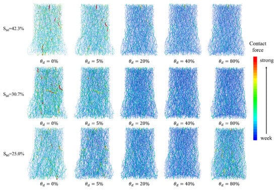
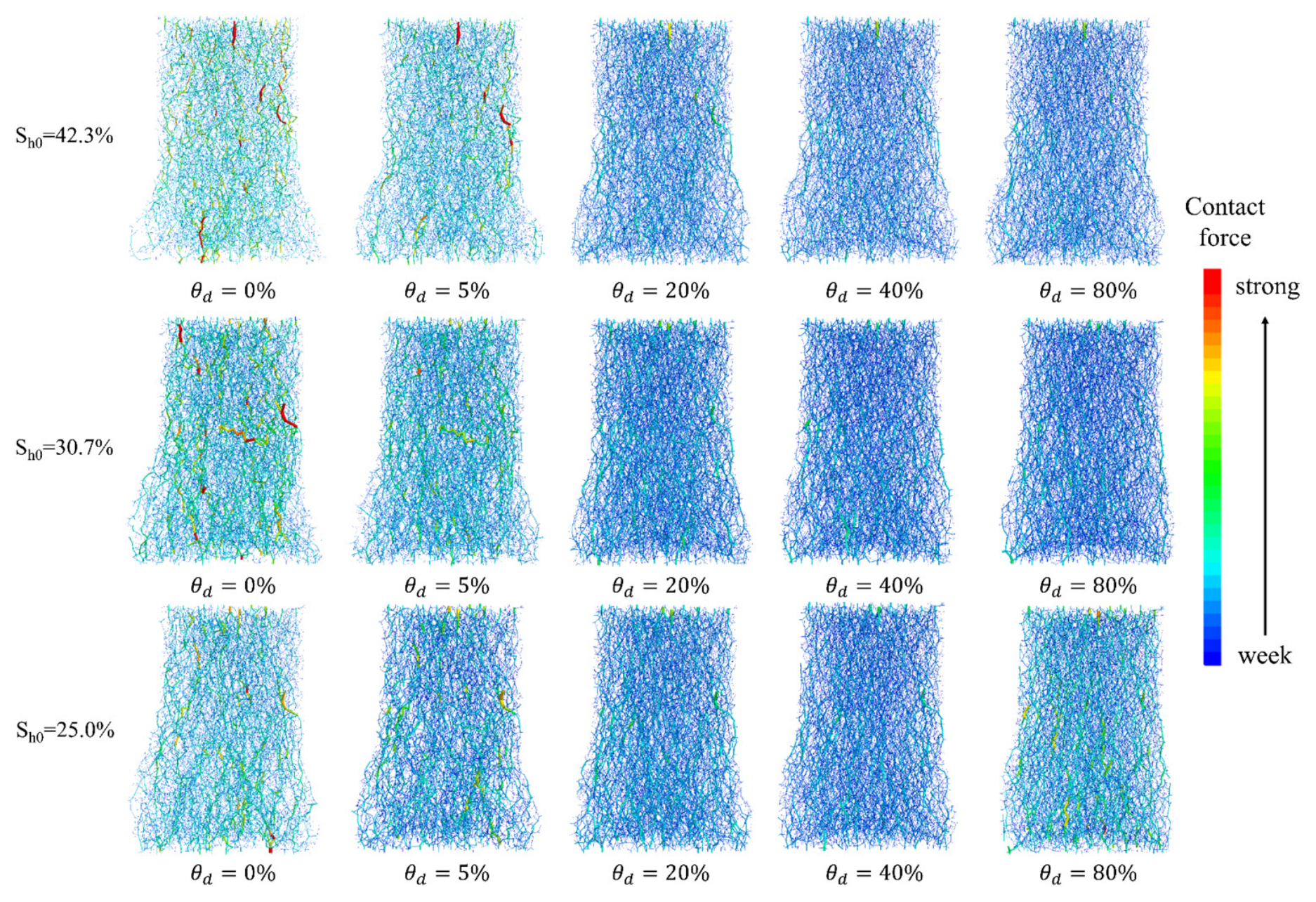
The final force chain distribution patterns for HBS with varying initial hydrate saturations and dissociation ratios after shearing are shown in Figure 10. Similarly, in HBS without hydrate dissociation, the number of strong force chains within the specimen gradually decreases as the initial hydrate saturation declines. Hydrate dissociation disrupts the cementation between sediment particles, rendering the interparticle force chains incapable of sustaining high shear stresses; consequently, they progressively transform into weak force chains oriented in other directions. Notably, regardless of the initial hydrate saturation, once the hydrate dissociation ratio reaches 20%, the final force chain distributions across specimens become essentially identical. This indicates that when the hydrate dissociation ratio exceeds 20%, the influence of the remaining hydrates on sediment particles is very limited. The initial hydrate saturation significantly influences the final deformation mode of HBS. Similarly, as the hydrate dissociation ratio increases, the final degree of deformation decreases slightly. This is likely because the binding effect among particles within HBS weakens, rendering the specimen more compressible and thus reducing its volumetric expansion. Notably, once the hydrate dissociation ratio exceeds 20%, there is virtually no difference in the final deformation mode. This further indicates that beyond a dissociation ratio of 20%, the binding effect exerted by hydrates between sediment grains becomes negligible.
Figure 10.
The final force chain distribution patterns for HBS with varying initial hydrate saturations and dissociation ratios after shearing.
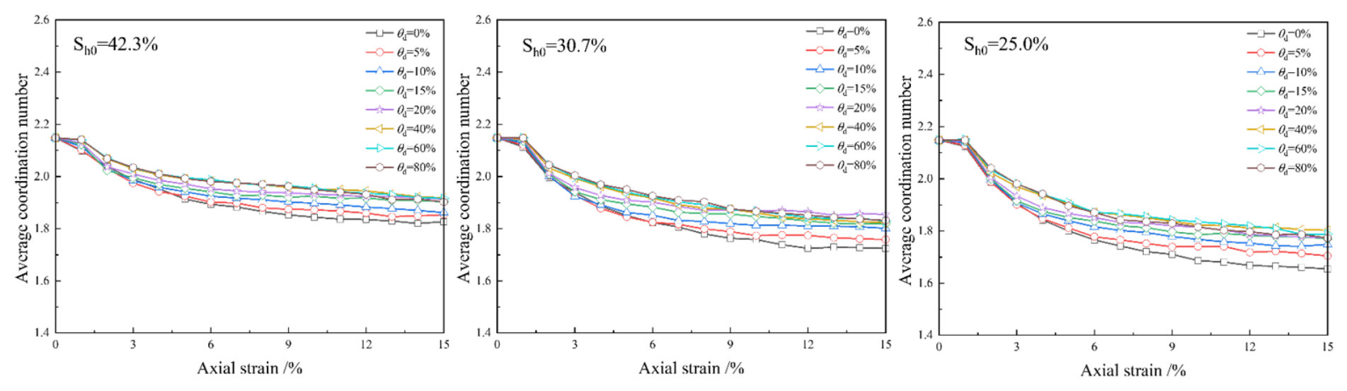
To provide a clearer illustration of how individual particles participate in force chain transmission, Figure 11 presents the evolution of the average coordination number of particles within HBS under various initial hydrate saturations and dissociation ratios. A higher initial hydrate saturation corresponds to a larger average coordination number, indicating tighter interparticle contacts. The strength, stiffness, and toughness of a granular system all depend on the contact force transmission pathways among particles [39,40,41]. A higher coordination number implies a more developed stress chain network, which in turn yields greater macroscopic stiffness and higher shear strength. This finding is consistent with experimental observations [28]. Upon hydrate dissociation, the average coordination number of HBS decreases in all cases, with particularly pronounced reductions observed in specimens having a low initial hydrate saturation. Moreover, the decline in the average coordination number during shearing is also more significant for these specimens. Owing to the weak cementation between sediment particles at low initial hydrate saturation, the particles possess a higher degree of freedom for movement. Under axial loading, they are unable to sustain high stresses and thus gradually disperse, leading to a substantial drop in the average coordination number. Although hydrate dissociation universally results in a marked reduction in macroscopic mechanical strength, notable differences persist in the mesoscopic evolution of force chains and the variation of the average coordination number [35]. This discrepancy may be attributed to the fact that the initial hydrate cementation influences both the migration mode and the contact mode of particles, ultimately giving rise to distinct structural evolutionary behaviors.
Figure 11.
The evolution of the average coordination number of particles within HBS under various initial hydrate saturations and dissociation ratios.
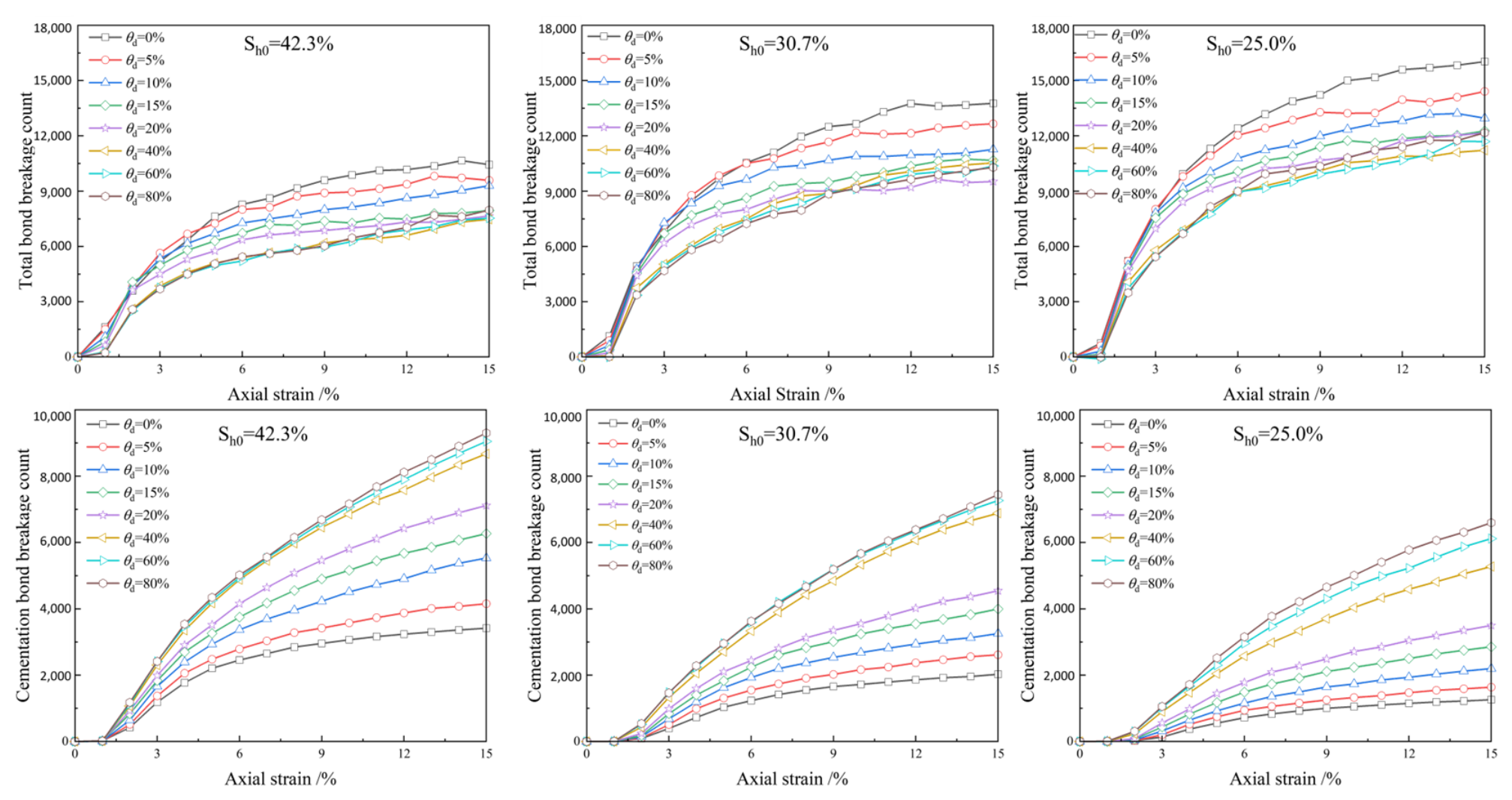
Figure 12 shows the evolution of the total bond breakage count and the cementation bond breakage count for HBS with varying initial hydrate saturations and dissociation ratios. From the total bond breakage count, it can be observed that specimens with a higher initial hydrate saturation exhibit fewer total bond breakages as axial strain increases, owing to the greater load-bearing capacity of interparticle contacts. However, when comparing the cementation bond breakage curves, specimens with a higher initial hydrate saturation display a larger cumulative number of cementation bond breakages than other specimens. This implies that, at higher initial hydrate saturations, the internal failure is dominated by the rupture of cementation bonds, whereas in other specimens, non-cementation bonds are predominantly broken. As the hydrate dissociation ratio increases, this disparity becomes increasingly pronounced. In particular, when the hydrate dissociation ratio reaches 20%, the incidence of cementation bond breakage rises markedly.
Figure 12.
The evolution of the total bond breakage count and the cementation bond breakage count for HBS with varying initial hydrate saturations and dissociation ratios.
3.5. Strength Degradation Mechanism
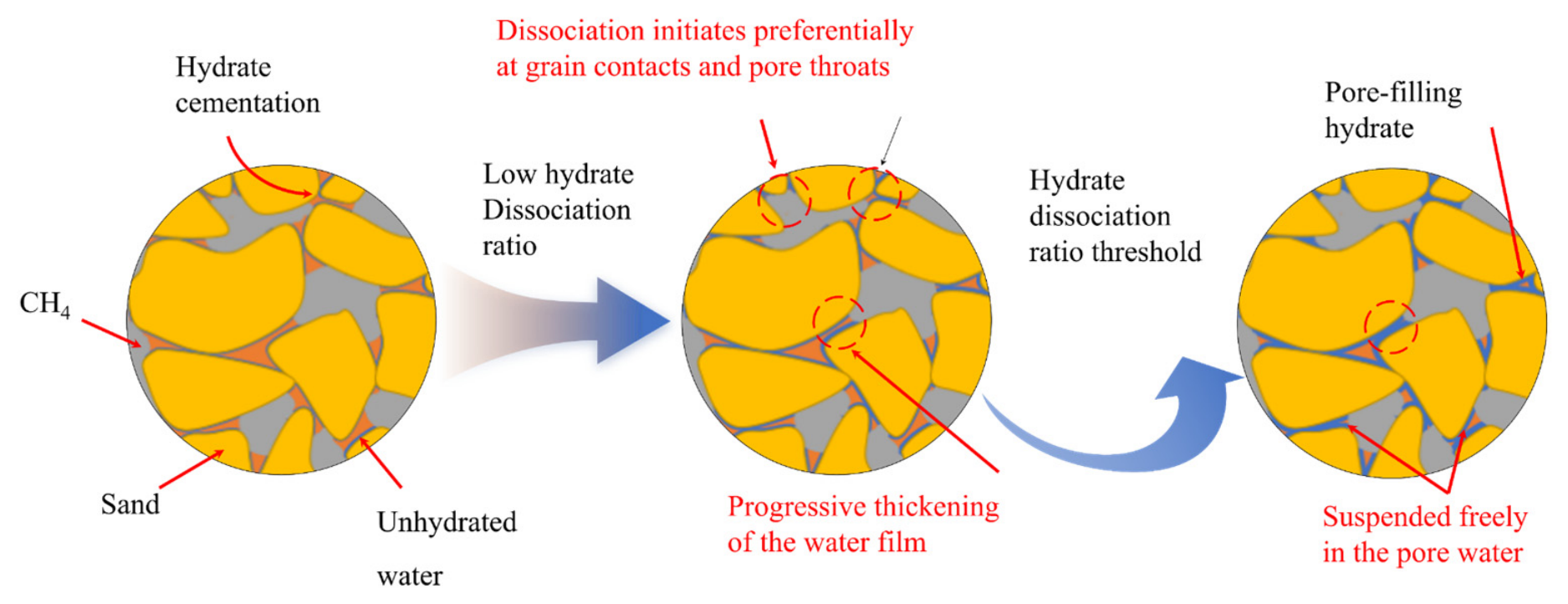
From the above results, it can be seen that the strength of HBS is not solely influenced by the hydrate saturation within the sediments. Figure 13 illustrates the conceptual schematic evolution of microstructural characteristics during the hydrate dissociation process. Previous studies have found that when hydrates undergo dissociation, it preferentially occurs at the interface where gas contacts the hydrate [42,43]. In contrast, hydrates located in small pores remain more stable due to capillary effects. At a low hydrate dissociation ratio, cementing hydrates at the grain contact points on the walls of large pores and at pore throats dissociate first, leading to a sharp weakening of the cementation effect. Subsequently, the sediment structure is disrupted, resulting in a significant decrease in strength. On the other hand, hydrate dissociation generates water and gas. The dissociated water accumulates on the surface of sediment particles, thickening the water film and thereby weakening the frictional force between soil particles [44,45]. Meanwhile, the combined action of gas and water flow may detach some hydrates from the soil particles, causing residual hydrates to float in the interstitial water, which continuously undermines the strength of HBS. When the hydrate dissociation ratio reaches a certain extent, extensive dissociation alters the occurrence mode of hydrates, transitioning from cementing type to pore-filling type. At this stage, most residual hydrates are suspended in the interstitial water, exerting negligible influence on strength. The strength is primarily governed by the soil particle skeleton itself and the cementing hydrates in some small pores. As hydrate dissociation continues, the differences in strength among HBS gradually diminish or even become invariant.
Figure 13.
The conceptual schematic evolution of microstructural characteristics during the hydrate dissociation process.
The strength enhancement of HBS primarily originates from the cementation effect of hydrates, and hydrate dissociation preferentially initiates at the hydrate–sediment particle contact interface [46]. Samples with higher initial hydrate saturation possess relatively more cementation contact points, implying that the soil particle skeleton undergoes simultaneous fracturing at a greater number of connections. This instantaneous collapse of the sediment skeleton leads to a rapid decline and substantial degradation in strength for specimens with high initial hydrate saturation. Moreover, the higher the initial hydrate saturation, the greater the amount of water and gas generated under the same hydrate dissociation ratio. The production of dissociated water continuously weakens the frictional force between soil particles. At the same time, a large volume of gas generated in a short period cannot be discharged instantaneously; local accumulation causes a sharp increase in pore pressure. On one hand, the elevated pressure significantly reduces the effective stress between particles, thereby lowering the shear strength of the soil mass. On the other hand, the pressure generated inside the pores further detaches hydrate particles, making them more susceptible to shear failure, thus accelerating strength degradation [47].
For HBS with lower initial hydrate saturation, the strength gain is entirely governed by the cementation effect of hydrates [2]. Hydrate dissociation leads to a drastic disruption of the sediment structure, resulting in a rapid decline in strength. When the hydrate dissociation ratio reaches a certain value, the meltwater generated from hydrate dissociation accumulates in the contact zones between sediment particles. While providing lubrication, this accumulation also promotes the transition of the hydrate occurrence mode from a cementing type to a pore-filling type. However, pore-filling hydrates have a minor influence on strength, and the specimen strength does not undergo significant changes with further hydrate dissociation.
In the future development of constitutive models, the hydrate saturation should not only account for its residual value but also incorporate its dissociation history. That is, only when the initial hydrate saturation and the hydrate dissociation ratio are given can the mechanical behavior of HBS be predicted with greater accuracy.
4. Conclusions
This study investigated the mechanical behavior of HBS under various conditions of initial hydrate saturation and dissociation ratio using discrete element simulations. The main conclusions are as follows:
- (1)
- For HBS with high initial hydrate saturation, even a small amount of hydrate dissociation leads to a significant decrease in their mechanical strength.
- (2)
- For specimens with different initial hydrate saturations, although the strength of HBS and the hydrate dissociation ratio cannot be described by a single equation, the evolution of their microscopic parameters conforms to a unified function.
- (3)
- For specimens with high initial saturation, the abundance of cementation contact points leads to a rapid loss of the cementation effect upon hydrate dissociation, resulting in a sharp decline in strength. In contrast, for specimens with low initial saturation, the hydrate occurrence mode transitions from cementing type to pore-filling type at later stages of hydrate dissociation, causing the strength variation to level off.
- (4)
- When assessing the mechanical properties of HBS, hydrate saturation and dissociation path must also be taken into account; otherwise, substantial prediction errors may arise.
Author Contributions
Conceptualization, Q.W. and R.Y.; methodology, X.L. and S.Z.; software, R.Y.; validation, Q.W. and Y.D.; formal analysis, H.M.; data curation, S.Z.; writing—original draft preparation, Q.W. and H.M.; writing—review and editing, D.Y. and X.D. Funding acquisition, Q.W., R.Y., D.Y. and X.D. Supervision, H.M.; Project administration, H.M. All authors have read and agreed to the published version of the manuscript.
Funding
This research was supported by the National Natural Science Foundation of China (No. 42306237), the Natural Science Foundation of Guangxi (No. 2025GXNSFBA069399), and the National Natural Science Foundation of China (No. 42562034, 12262009, 42407238, 42506225).
Data Availability Statement
Data can be obtained from the corresponding author upon reasonable request.
Conflicts of Interest
The authors declare no conflicts of interest.
Nomenclature
| Shear stiffness (Linear) | |
| Normal stiffness (Linear) | |
| s | Shear stiffness (Parallel-Bond) |
| n | Normal stiffness (Parallel-Bond) |
| Surface gap | |
| Tensile strength | |
| Friction coefficient | |
| Normal stress at bond periphery | |
| Cohesion |
Appendix A. Parameter Optimization for DEM Model
| Parameters | Optimization Values |
| RR-linear model | |
| Effective modulus [Pa] | 0.8 × 10⁹ |
| Normal-to-shear stiffness ratio | 1.33 |
| Friction coefficient | 0.4 (sand–sand contacts) |
| 0 (sand–facet contacts) | |
| Rolling resistance coefficient | 0.3 (sand–sand contacts) |
| 0 (sand–facet contacts) | |
| linear-PB model | |
| Effective modulus [Pa] | 5 × 10¹⁰ |
| Normal-to-shear stiffness ratio | 1.2 |
| Friction coefficient | 0.3 |
| Parallel-bond effective modulus [Pa] | 3.0 × 10⁸ |
| Parallel-bond normal-to-shear stiffness ratio | 1.2 |
| Parallel-bond tensile strength [Pa] | 30.0 × 10⁷ |
| Parallel-bond cohesion strength [Pa] | 19.5 × 10⁷ |
References
- Sloan, E.D. Fundamental Principles and Applications of Natural Gas Hydrates. Nature 2003, 426, 353–359. [Google Scholar] [CrossRef] [Scilit] [PubMed]
- Ning, F.; Yu, Y.; Kjelstrup, S.; Vlugt, T.J.H.; Glavatskiy, K. Mechanical Properties of Clathrate Hydrates: Status and Perspectives. Energy Environ. Sci. 2012, 5, 6779. [Google Scholar] [CrossRef] [Scilit]
- Gajanayake, S.M.; Gamage, R.P.; Li, X.-S.; Huppert, H. Natural Gas Hydrates—Insights into a Paradigm-Shifting Energy Resource. Energy Rev. 2023, 2, 100013. [Google Scholar] [CrossRef] [Scilit]
- Liang, Y.; Tan, Y.; Luo, Y.; Zhang, Y.; Li, B. Progress and Challenges on Gas Production from Natural Gas Hydrate-Bearing Sediment. J. Clean. Prod. 2020, 261, 121061. [Google Scholar] [CrossRef] [Scilit]
- Yang, M.; Zhao, J.; Zheng, J.; Song, Y. Hydrate Reformation Characteristics in Natural Gas Hydrate Dissociation Process: A Review. Appl. Energy 2019, 256, 113878. [Google Scholar] [CrossRef] [Scilit]
- Li, B.; Liu, S.-D.; Liang, Y.-P.; Liu, H. The Use of Electrical Heating for the Enhancement of Gas Recovery from Methane Hydrate in Porous Media. Appl. Energy 2018, 227, 694–702. [Google Scholar] [CrossRef] [Scilit]
- Yan, C.; Ren, X.; Cheng, Y.; Song, B.; Li, Y.; Tian, W. Geomechanical Issues in the Exploitation of Natural Gas Hydrate. Gondwana Res. 2020, 81, 403–422. [Google Scholar] [CrossRef] [Scilit]
- Zhao, Y.; Hu, G.; Liu, L.; Liu, C.; Wan, Y.; Bu, Q.; Ji, Y.; Zhang, Z.; Kong, L. Mechanical Properties of Gas Hydrate-Bearing Sediments: Research Progress, Challenges and Perspectives. Earth-Sci. Rev. 2025, 262, 105058. [Google Scholar] [CrossRef] [Scilit]
- Wang, L.; Yu, W.; Zhang, K.; Liu, Z.; Wu, Z.; Liu, Z.; Ma, S.; Li, Y. Strength Characteristics of Fractured Methane Hydrate-Bearing Sediments. Eng. Fract. Mech. 2025, 319, 110986. [Google Scholar] [CrossRef] [Scilit]
- Wu, Y.; Hyodo, M.; Cui, J. On the Critical State Characteristics of Methane Hydrate-Bearing Sediments. Mar. Pet. Geol. 2020, 116, 104342. [Google Scholar] [CrossRef] [Scilit]
- Ma, H.-L.; Feng, X.-L.; Liu, L.-L.; Zhang, A.; Wang, D. Changes in the Effective Absolute Permeability of Hydrate-Bearing Sands during Isotropic Loading and Unloading. Pet. Sci. 2026, 23, 998–1013. [Google Scholar] [CrossRef] [Scilit]
- You, Z.; Hao, Y.; Hu, W.; Shen, S.; Wu, P.; Li, Y. Strength Analysis of Hydrate-Bearing Sandy Sediments in Excess Gas and Excess Water Based on Drained Triaxial Compression Tests. Eng. Geol. 2023, 325, 107292. [Google Scholar] [CrossRef] [Scilit]
- Kim, J.; Zhang, Y.; Seol, Y.; Dai, S. Particle Crushing in Hydrate-Bearing Sands. Geomech. Energy Environ. 2020, 23, 100133. [Google Scholar] [CrossRef] [Scilit]
- Li, Y.; Hu, W.; Tang, H.; Wu, P.; Liu, T.; You, Z.; Yu, T.; Song, Y. Mechanical Properties of the Interstratified Hydrate-Bearing Sediment in Permafrost Zones. Energy 2023, 282, 128970. [Google Scholar] [CrossRef] [Scilit]
- Sun, Y.; Cheng, Y.; Zhao, J.; Yan, C.; Shi, X.; Shi, F. Strength Properties and Strength Criterion of Unconsolidated Hydrate-Bearing Sediment under the Effect of Clay Minerals. Appl. Ocean Res. 2025, 163, 104738. [Google Scholar] [CrossRef] [Scilit]
- Yu, J.; Cheng, C.; Yang, J. Evolution Characteristics of the Strength and Dilation Parameters of Gas Hydrate-Bearing Sediments and a Modeling Study. Appl. Sci. 2024, 14, 2517. [Google Scholar] [CrossRef] [Scilit]
- Yoneda, J.; Suzuki, K.; Oshima, M.; Muraoka, M.; Jin, Y. Empirical Evaluation of the Strength and Deformation Characteristics of Natural and Synthetic Gas Hydrate-Bearing Sediments with Different Ranges of Porosity, Hydrate Saturation, Effective Stress, and Strain Rate. Prog. Earth Planet. Sci. 2024, 11. [Google Scholar] [CrossRef] [Scilit]
- Kajiyama, S.; Hyodo, M.; Nakata, Y.; Yoshimoto, N.; Wu, Y.; Kato, A. Shear Behaviour of Methane Hydrate Bearing Sand with Various Particle Characteristics and Fines. Soils Found. 2017, 57, 176–193. [Google Scholar] [CrossRef] [Scilit]
- Lei, L.; Seol, Y.; Choi, J.-H.; Kneafsey, T.J. Pore Habit of Methane Hydrate and Its Evolution in Sediment Matrix—Laboratory Visualization with Phase-Contrast Micro-CT. Mar. Pet. Geol. 2019, 104, 451–467. [Google Scholar] [CrossRef] [Scilit]
- Lei, L.; Liu, Z.; Seol, Y.; Boswell, R.; Dai, S. An Investigation of Hydrate Formation in Unsaturated Sediments Using X-Ray Computed Tomography. J. Geophys. Res. Solid Earth 2019, 124, 3335–3349. [Google Scholar] [CrossRef] [Scilit]
- Wang, L.; Zhao, J.; Sun, X.; Wu, P.; Shen, S.; Liu, T.; Li, Y. Comprehensive Review of Geomechanical Constitutive Models of Gas Hydrate-Bearing Sediments. J. Nat. Gas Sci. Eng. 2021, 88, 103755. [Google Scholar] [CrossRef] [Scilit]
- Sun, Y.; Zhang, Y.; Liu, L.; Lu, J.; Tian, S.; Li, G. Strength Behaviors and Constitutive Model of Gas-Saturated Methane Hydrate-Bearing Sediment in Gas-Rich Phase Environment. J. Mar. Sci. Eng. 2023, 11, 142. [Google Scholar] [CrossRef] [Scilit]
- Uchida, S.; Xie, X.-G.; Leung, Y.F. Role of Critical State Framework in Understanding Geomechanical Behavior of Methane Hydrate-Bearing Sediments. J. Geophys. Res.-Solid Earth 2016, 121, 5580–5595. [Google Scholar] [CrossRef] [Scilit]
- Uchida, S.; Soga, K.; Yamamoto, K. Critical State Soil Constitutive Model for Methane Hydrate Soil. J. Geophys. Res.-Solid Earth 2012, 117, B03209. [Google Scholar] [CrossRef] [Scilit]
- Wang, Z.; Qi, C.; Yu, H.; Zhao, F.; Luo, Y. Elastoplastic Constitutive Model for Gas Hydrate Bearing Sediments Considering Hydrate Occurrence Habits. Geomech. Geophys. Geo-Energy Geo-Resour. 2022, 8, 190. [Google Scholar] [CrossRef] [Scilit]
- Zhang, Y.; Wei, J.; Zhang, X.; Ren, W.; Lu, X.; Guo, H.; Wang, T. Linear Stability and Numerical Analysis of Gas Hydrate Dissociation in Hydrate Bearing Sediments. Appl. Ocean Res. 2025, 154, 104394. [Google Scholar] [CrossRef] [Scilit]
- Yang, D.; Zhu, Z.; Fan, Q.; Yan, M.; Yan, R.; Wei, C. The Shear Strength Characteristics and Weakening Effect of Methane Hydrate-Bearing Sediments under Partial Hydrate Dissociation. Int. J. Geomech. 2026, 26, 04025297. [Google Scholar] [CrossRef] [Scilit]
- Yang, D.; Chen, C.; Wu, Q.; Wu, Y.; Wei, C.; Yan, R. Mechanical Behavior of Methane Hydrate-Bearing Sediments with Various Hydrate Saturations and Morphologies under a Complicated Environment. J. Ocean Eng. Sci. 2026. [Google Scholar] [CrossRef] [Scilit]
- Hyodo, M.; Nakata, Y.; Yoshimoto, N.; Ebinuma, T. Basic Research on the Mechanical Behavior of Methane Hydrate-Sediments Mixture. Soils Found. 2005, 45, 75–85. [Google Scholar]
- Dou, X.; Wu, Q.; Liu, Z.; Zhao, Y.; Li, Y.; Gao, D.; Ning, F. Effects of Hydrate Distribution Heterogeneity on the Mechanical Properties of Hydrate-Bearing Sediments with Consideration of the Coalescence Phenomenon: Insights from DEM Simulations. Comput. Geotech. 2023, 162, 105627. [Google Scholar] [CrossRef] [Scilit]
- Wu, Q.; Dou, X.; Zhao, Y.; Liu, Z.; Li, Y.; Yoshimoto, N.; Ning, F. Discrete Element Simulation of the Hydrate-Bearing Sediments Mechanical Behaviors under Typical Hydrate Dissociation Patterns. Gas Sci. Eng. 2023, 115, 205020. [Google Scholar] [CrossRef] [Scilit]
- Ding, Y.; Qian, A.; Lu, H. Applications of the Discrete Element Method for Gas Hydrate-Bearing Sediments: Recent Advances and Perspectives. Energy Fuels 2022, 36, 10766–10784. [Google Scholar] [CrossRef] [Scilit]
- Dou, X.; Liu, Z.; Ning, F.; Li, Y.; Li, X.; Zhao, Y.; Hu, W.; Gao, D. 3D DEM Modeling on Mechanical Weakening of Gas Hydrate-Bearing Sandy Sediments during Hydrate Dissociation. Comput. Geotech. 2023, 154, 105116. [Google Scholar] [CrossRef] [Scilit]
- Jiang, M.; Shen, Z.; Wang, J. A Novel Three-Dimensional Contact Model for Granulates Incorporating Rolling and Twisting Resistances. Comput. Geotech. 2015, 65, 147–163. [Google Scholar] [CrossRef] [Scilit]
- Wu, Q.; Liu, X.; Yan, R.; Yang, D.; Dou, X.; Lu, J.; Li, D.; Yoshimoto, N. Dynamic Pore Architecture Transformation of Hydrate-Bearing Sediments during Shearing: A DEM Micro-Mechanical Perspective. Granul. Matter 2026, 28, 106. [Google Scholar] [CrossRef] [Scilit]
- Liu, J.-W.; Li, X.-S.; Kou, X.; Wang, Y.; Li, L.-J. Analysis of Hydrate Heterogeneous Distribution Effects on Mechanical Characteristics of Hydrate-Bearing Sediments. Energy Fuels 2021, 35, 4914–4924. [Google Scholar] [CrossRef] [Scilit]
- Tian, B.; You, Z.; Wu, P.; Song, Y.; Li, Y. Stress-Strain Response and Particle-Scale Behavior of Sandy Sediments Containing Hydrate Interlayer: A Numerical Investigation Using DEM. Gas Sci. Eng. 2025, 134, 205541. [Google Scholar] [CrossRef] [Scilit]
- Yoshimoto, N.; Wu, Q.; Fujita, K.; Kajiyama, S.; Nakata, Y.; Hyodo, M. Hydrate Dissociation and Mechanical Properties of Hydrate-Bearing Sediments under Local Thermal Stimulation Conditions. Gas Sci. Eng. 2023, 116, 205045. [Google Scholar] [CrossRef] [Scilit]
- Jiang, M.; Chen, H.; Tapias, M.; Arroyo, M.; Fang, R. Study of Mechanical Behavior and Strain Localization of Methane Hydrate Bearing Sediments with Different Saturations by a New DEM Model. Comput. Geotech. 2014, 57, 122–138. [Google Scholar] [CrossRef] [Scilit]
- Gong, B.; Zhang, R.; Ye, R.; Jiang, Y.; Zhang, B. Mechanical Response of Stratified Methane Hydrate Reservoirs: Multiscale Insights into Dip Angle Effects on Geomechanical Stability. Gas Sci. Eng. 2026, 145, 205791. [Google Scholar] [CrossRef] [Scilit]
- Jiang, M.; He, J.; Wang, J.; Zhou, Y.; Zhu, F. Discrete Element Analysis of the Mechanical Properties of Deep-Sea Methane Hydrate-Bearing Soils Considering Interparticle Bond Thickness. Comptes Rendus Méc. 2017, 345, 868–889. [Google Scholar] [CrossRef] [Scilit]
- Yang, J.; Wang, Y.; Wang, P.; Zhu, J.; Chen, Y.J. Unveiling Gas Hydrate Dynamics: A Microfluidic Investigation of Formation, Decomposition Pathways, and Kinetic Impacts. Gas Sci. Eng. 2025, 142, 205709. [Google Scholar] [CrossRef] [Scilit]
- Li, X.; Wei, H.; Li, X.; Wang, Y.; Zhou, S.; Liu, Y.; Lv, X.; Rao, Y. Experimental Study on the Microscopic Dissociation Behavior of Methane Hydrate in Pore-Scale through Direct Visualization. Chem. Eng. Sci. 2025, 306, 121301. [Google Scholar] [CrossRef] [Scilit]
- Lei, L.; Seol, Y.; Myshakin, E.M. Methane Hydrate Film Thickening in Porous Media. Geophys. Res. Lett. 2019, 46, 11091–11099. [Google Scholar] [CrossRef] [Scilit]
- Pan, L.; Lei, L.; Seol, Y. Pore-Scale Influence of Methane Hydrate on Permeability of Porous Media. J. Nat. Gas Sci. Eng. 2021, 87, 103758. [Google Scholar] [CrossRef] [Scilit]
- Hou, X.; Qi, S.; Huang, X.; Guo, S.; Zou, Y.; Ma, L.; Zhang, L. Hydrate Morphology and Mechanical Behavior of Hydrate-Bearing Sediments: A Critical Review. Geomech. Geophys. Geo-Energy Geo-Resour. 2022, 8, 161. [Google Scholar] [CrossRef] [Scilit]
- Zhou, Y.; Zhou, J.; Chen, P.; Wei, C. Shear Strength Degradation of Gas Hydrate-Bearing Sediment Due to Partial Hydrate Dissociation. J. Rock Mech. Geotech. Eng. 2024, 16, 2749–2763. [Google Scholar] [CrossRef] [Scilit]

Disclaimer/Publisher’s Note: The statements, opinions and data contained in all publications are solely those of the individual author(s) and contributor(s) and not of MDPI and/or the editor(s). MDPI and/or the editor(s) disclaim responsibility for any injury to people or property resulting from any ideas, methods, instructions or products referred to in the content. |
© 2026 by the authors. Licensee MDPI, Basel, Switzerland. This article is an open access article distributed under the terms and conditions of the Creative Commons Attribution (CC BY) license.