


Abstract
To fill up the research gap on immersed tunnel towing in restricted waters, towing tank experiments are conducted in this study to investigate the hydrodynamic resistance of a novel catamaran-assisted tunnel towing system under combined shallow-water and bank-confined conditions. The influences of the multi-body hydrodynamic interactions on the resistance performance of the towing system are highlighted. The results reveal that the shallow-water effect aggravates the total resistance by 44.2% for the integrated towing system and the bank effect introduces an additional 14.2% rise. The catamaran–tunnel system exhibits stronger sensitivity to the shallow water than the standalone catamaran, reaching 15.57-fold and 6.73-fold of those of the isolated catamaran across the entire test range. Furthermore, the confined water effects contribute to a high residual resistance share in total resistance, attaining 80.9% for the single catamaran and 96.0% for the coupled system in confined waterways.
1. Introduction
Amidst the accelerating economic progress and the vigorous development of coastal cities, enhancing traffic infrastructure across bays and straits has become a critical priority. Distinct from conventional tunneling methods, immersed tube tunnels offer a unique combination of optimal route alignment, structural stability, and superior seismic resilience, playing a pivotal role in the development of underwater transportation networks. The construction of immersed tube tunnels entails a systematic process wherein massive precast concrete segments are manufactured onshore, and towed to the installation site for assembly, which features extended transit distance and complicated channel constraints. This is particularly true as the immersed tunnel evolves towards larger dimensions and small freeboard, which renders inevitable shallow-water effect and bank effect on the towing vessels and adversely influences their maneuverability and stability. Thus, it is imperative to examine the towing characteristics of immersed tunnels in restricted waters for further improvement of the prediction accuracy and advancement of immersed tunnel technology.
To date, existing research on immersed tube tunnels predominantly focuses on structural mechanical characteristics, the joint waterproofing performance, foundation stability and seismic analysis. In comparison, far less effort has been devoted to offshore construction operations, particularly the hydrodynamic responses of tunnel elements during the floating transportation and installation processes. Regarding the initial launch of zero-freeboard tunnel segments, Huang et al. [1] highlighted the critical influence of green water occurrence on the frequent slack-taut of the suspension lines and this was mitigated effectively by suitable ballasting, as reported by Song et al. [2]. Zhou et al. [3] developed and optimized the ballast water system for immersed tube installation construction. Building upon this foundation, Song et al. [4] and Song et al. [5,6] performed systematic experimental and numerical studies to reveal the influence of the lowering depth on the coupled hydrodynamic characteristics of the tunnel-barge installation system subjected to wave excitation. Unlike the well-established hydrodynamic research on the lowering of tunnel segments, the research concerning tunnel towing remains notably scarce and limited to a single tunnel segment during transit, such as Xiao et al. [7], Wu et al. [8] and Wu et al. [9]. Note that existing literature has primarily focused on the hydrodynamic forces on the sole tunnel segment in open water. In practice, the tunnel segments with large tonnage possess a deep draught and a rather low water depth-to-draft ratio, which easily counters the shallow-water effect and bank effect during long-distance towing. It has been reported that ship speed was decreased by up to 30% due to the shallow-water effect [10], and this reduction reached as high as 60% in rivers or canals [11]. However, to the best of the authors’ knowledge, confined-water effects on tunnel-towing operations and the inherent coupled hydrodynamic interactions between the immersed tunnel and towing barges remain poorly understood, and deeper physical insights into these phenomena are highly desirable.
Based on the International Towing Tank Conference (ITTC) Manoeuvring Committee’s reports and contemporary research, the analysis of ship hydrodynamic performance in restricted waters primarily employs three methodologies: model tests in towing tanks, numerical computations grounded in potential flow theory, and computational fluid dynamics (CFD) simulations. Adopting potential flow theory, Müller [12] carried out a numerical study on the restricted water depth and Yao et al. [13] on the bank effect on the ship resistance. However, the assumption of negligible viscous effects becomes invalid when the water depth-to-draft ratio falls below 1.3, and thus the potential flow solutions yield inaccurate results [14]. In light of this, CFD simulations were performed to investigate the shallow-water effect by Wang and Zou [15] for a bulk carrier ship and Li et al. [16] for an offshore wind farm O&M catamaran. Given the strong sensitivity to the specified boundary conditions in CFD modeling, conducting model tests remains the most reliable method for assessing ship hydrodynamics in restricted waterways and for providing critical validation for numerical models. Du et al. [17] combined CFD and experimental approaches to analyze the resistance for an inland convoy as a function of water depth, pier distance and draft. The influence of bridge piers on the mean properties was found to be marginal. The effect of water depth on the resistance, propulsion and maneuvering performances of an inland ship was analyzed by Wu et al. [18] and Mucha et al. [19], considering varying towing speeds. The blockage effect of the narrow canal was experimentally examined by Elsherbiny et al. [20] on the KCS and by Liu et al. [21] on the KVLCC2. However, these existing studies address shallow-water effects or side-bank blockage independently for a single floating vessel. Thus, their empirical power-law relations are derived from isolated single-hull cases at specific blockage ratios in unconfined shallow waters, neglecting vertical sidewall confinement and multi-body hydrodynamic interference between catamaran and tunnel. Hence, the current design specifications are hardly applicable to the catamaran-assisted towing of the tunnel under coupled shallow-water and side-wall blockage conditions.
In light of this, towing tank experiments are performed in this study to address two major research gaps. On one hand, experimental quantification of their synergistic coupled influences on the resistance of the catamaran-assisted tunnel towing system is still lacking, even though this coupled hydrodynamic condition dominates the safety of real tunnel towing operations. Hence, in this study, the measured resistance and the derived dimensionless confined-water-effect ratio form physical correlations instead of pure mathematical curve fitting. This can directly support the design and safety evaluation of immersed-tunnel transportation within narrow restricted waterways. On the other hand, this study examines multi-body hydrodynamic interactions between the catamaran and the blunt tunnel element by comparing unladen and loaded towing cases. To the authors’ knowledge, experimental measurements targeting this specific coupled floating system under combined shallow-water and bank confinement have rarely been reported in the available literature. Note that the present physical model tests without detailed flow field data do not account for flow-field contours and pressure distributions. And the direct quantitative comparisons against independent CFD or full-scale data are unavailable for visual validation, leading to limitations in the inherent physical mechanisms. Despite this, the existing experimental results herein provide valuable technical support for the promotion of the catamaran towing method as well as essential insights into the hydrodynamic behaviors of large blunt bodies in confined waterways.
2. Materials and Methods
2.1. The Physical Model and Similarity Criteria
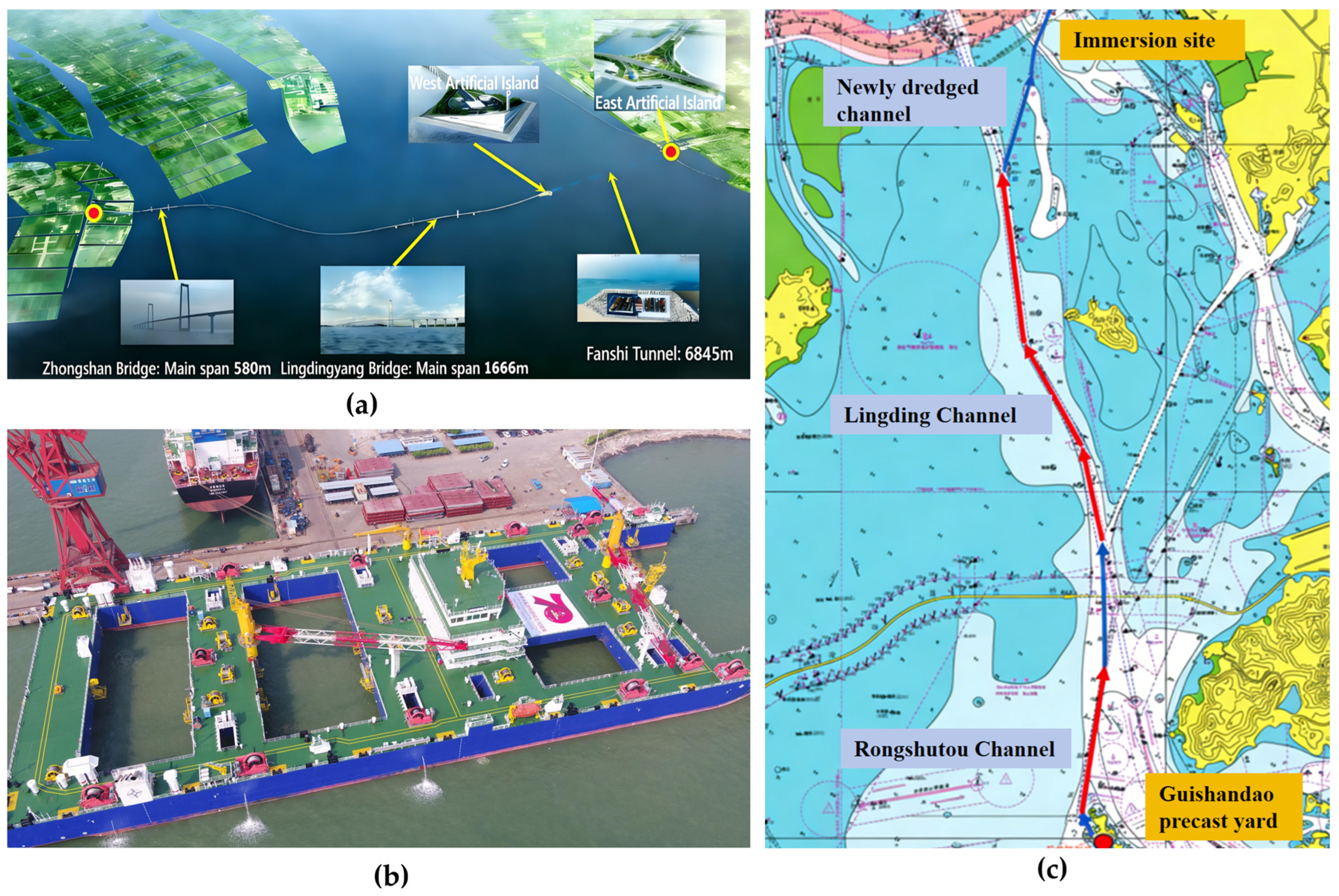
To assess the towing performance of the catamaran for large immersed tunnels, the Shenzhen–Zhongshan Link is adopted as the prototype for model fabrication in this study. As illustrated in Figure 1a, the Shenzhen–Zhongshan Link, spanning a critical maritime artery of 22.4 km across the Pearl River Estuary, is featured by a submerged tunnel section of 6.8 km within the Lingdingyang channel. The tunnel section is comprised of 32 prefabricated tube elements joined to form a final closure, each of which measures a dimension of 165 m in length, 46 m in width, and 10.6 m in height, weighing approximately 80,000 tons. The towing catamaran (Figure 1b) is specifically designed with a twin-hull configuration with a cross deck, with an overall length of 190.4 m, a molded breadth of 75 m, and a molded depth of 14.7 m. To ensure operational stability, the catamaran itself is designed with a ballast draft of 6.6 m, which rises to 7.1 m during tunnel towing operations to bear the additional loads. Comprehensive principal dimensions and key dynamic parameters for both the tunnel element and the catamaran are summarized in Table 1. As depicted in the engineering scheme of Figure 1c, the towing route for the precast tunnel elements spans over 50 km from the Guishan Island prefabrication yard to the pre-dredged installation trench, including a newly dredged 10 km channel. Given the constraints imposed by the limited channel width along the entire route, the water depths and bank conditions in this study have been determined according to practical engineering.
Figure 1.
The towing strategy of the immersed tunnel in Shenzhong Link (a) Shenzhen–Zhongshan Link; (b) towing-installation integrated catamaran; (c) transportation route of the tunnel.
Table 1.
Geometrical and structural parameters of the catamaran and tunnel segment.
To accurately reproduce the real physical properties through model testing, it is essential to ensure that the fabricated tunnel and catamaran models satisfy the requirements of geometric, kinematic, and dynamic similarity. First of all, the gravity similarity criterion is applied in the model fabrication to ensure the equivalent Froude number in the prototype and model scale, which can be defined as
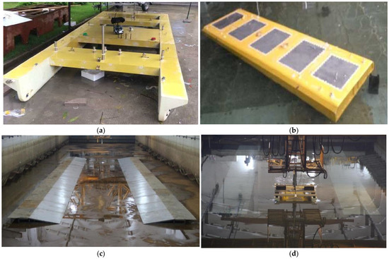
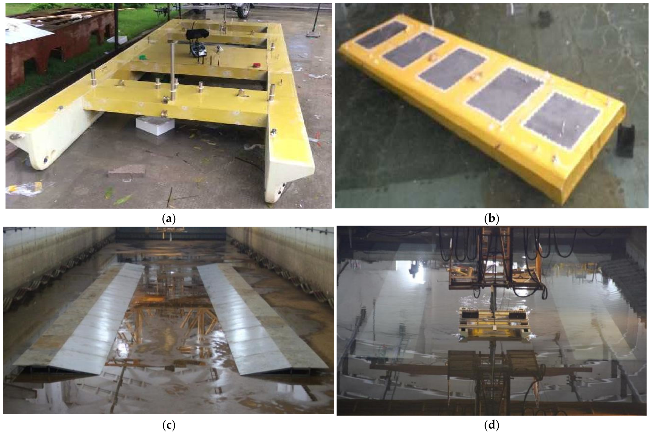
where V is the characteristic velocity, g is the gravitational acceleration, L is the characteristic length, and the subscripts m and p present the model scale and prototype ship, respectively. Given the constraints of the towing basin dimensions and the large scale of the full-scale tunnel element, a geometric scale ratio of λ = 40 was adopted for model fabrication based on Froude similarity principles. As summarized in Table 1, the geometric configurations and structural parameters of both the tunnel and catamaran models demonstrate a high degree of fidelity, with deviations within a tolerance of ±2%. This ensures the preservation of the essential geometric configurations and spatial relationships inherent to the prototype system, while mass equivalence and other critical mechanical parameters were meticulously calibrated to accurately replicate the full-scale dynamic behaviors. To guarantee structural integrity and watertightness during testing, both the scaled tunnel and catamaran models were fabricated from acrylic with a density of 1200 kg/m3 and an elastic modulus of 3.1 Gpa, and rigidly connected to eliminate any relative motion. The photos of the fabricated catamaran–tunnel towing system and the channel model during the tests are presented in Figure 2.
Figure 2.
The fabrication of the catamaran–tunnel towing system and channel bank. (a) The scale-down catamaran model in the tests; (b) the scale-down tunnel model in the tests; (c) photo of the fabricated model of channel bank; (d) photo of the towing system in channel.
Most importantly, to account for the viscous hydrodynamic interference of the flow field surrounding the hull, the Reynolds similarity should be achieved in the towing tests. However, under Froude scaling, it is practically impossible to achieve full Reynolds number similarity between the model and the prototype, introducing distortions and uncertainties in hull and propeller boundary-layer flows. Nevertheless, prior studies confirm that model boundary layers develop prototype-like turbulent features once the Reynolds number surpasses a critical value, thereby achieving acceptable viscous similarity for reliable hydrodynamic data. According to the 1978 ITTC Performance Committee, this critical Reynolds number was initially set at 2.0 × 10⁵, and later updated to 3.0 × 10⁵, as proposed by Shanghai JiaoTong University. According to the hull parameters illustrated in Table 1 and the forward speed in Table 2, the full-scale Reynolds number for the sole catamaran lies in 1.96 × 10⁸ to 1.17 × 10⁹, while the model-scale Reynolds number reaches 7.75 × 10⁵ to 4.64 × 10⁶. Regarding the catamaran–tunnel towing system, the full-scale Reynolds number lies in 1.96 × 10⁸ to 7.25 × 10⁸, while the model-scale Reynolds number ranges from 7.75 × 10⁵ to 2.87 × 10⁶. To further destabilize the boundary layer and promote its transition from laminar to turbulent flow, a flow trip wire of 1 mm diameter was installed at a distance of LPP/20 from the bow of the catamaran model. The wire location is chosen to trigger transition upstream of the gap flow and separation regions, so that a fully turbulent boundary layer develops over most of the wetted surface and matches the full-scale conditions. The non-dimensional wire height k/LPP = 0.001 and the ratio of wire diameter to the estimated local laminar boundary-layer thickness is k/δ = 0.87, which is large enough to achieve effective transition and small enough to avoid excessive additional drag. Thus, viscous similarity is acceptably approximated for the resistance performance measurements.
Table 2.
Test matrix of the resistance and propulsion performance study.
The towing tests were carried out in a towing tank of 474 m in length and 14 m in width. Given the width of the catamaran model of 1.875 m, the model-to-tank width ratio is 0.134, and the side clearance between the model and tank sidewall is approximately 6.06 m. The maximum draught of the model is 0.260 m, giving a bottom clearance of 0.0475 m to 0.740 m. The blockage ratio, defined as the ratio of the model submerged cross-sectional area to the tank cross-section, reaches 8.71% to 11.32% for the prototype water depth of 16 m and 12.3 m. Thus, the blockage effects should be considered and corrected according to Schuster’s equation in the ITTC recommendation. However, it should be noted that this correction cannot completely remove the viscous gap flow between the model bottom and tank floor. Fortunately, this residual viscous interference is consistent for all test cases and does not change the relative hydrodynamic trend.
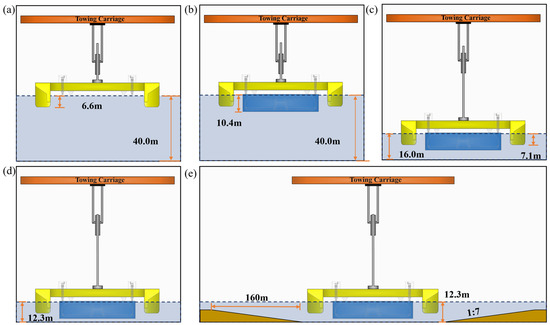
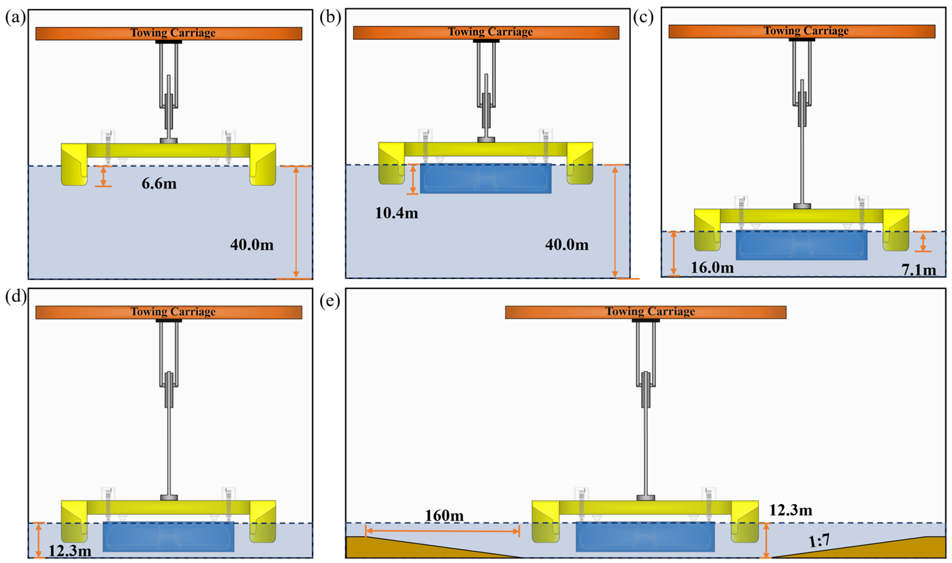
The schematic diagram of varying channel topology in the tests is depicted in Figure 3. According to the geological and hydrological conditions of the practical engineering project, three representative channel conditions were established: (a) an open-water channel with a water depth of 40.0 m in Figure 3a,b; (b) the main towing channel featuring a depth of 16.0 m in Figure 3c; and (c) the newly dredged channel characterized by a slope of angle tan θ = 1/7 and the original seabed of 6 m depth, resulting in a shallow-water depth of 12.3 m and a constraint bottom of 160 m in width as shown in Figure 3e. To isolate and evaluate the specific effects of shallow water and bank boundaries, a fourth baseline scenario was defined as an open-water channel with a depth of 12.3 m in Figure 3d. Furthermore, to accurately simulate the hydrodynamic constraints imposed by narrow channels, the side slopes of the dredged channel were physically reproduced as bank boundaries using PVC plates supported by steel structures. The photo of the scaled-down terrain model for the simulation of the newly dredged channel is given in Figure 2c.
Figure 3.
The schematic diagram of varying channel topology in the tests (a) catamaran in water depth of 40.0 m; (b) catamaran–tunnel towing system in water depth of 40.0 m; (c) catamaran–tunnel towing system in water depth of 16.0 m; (d) catamaran–tunnel towing system in water depth of 12.3 m; (e) catamaran–tunnel towing system in water depth of 12.3 m and bank terrain.
2.2. Experimental Setup and Measuring Apparatus
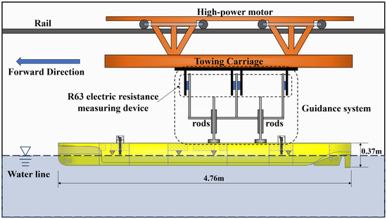
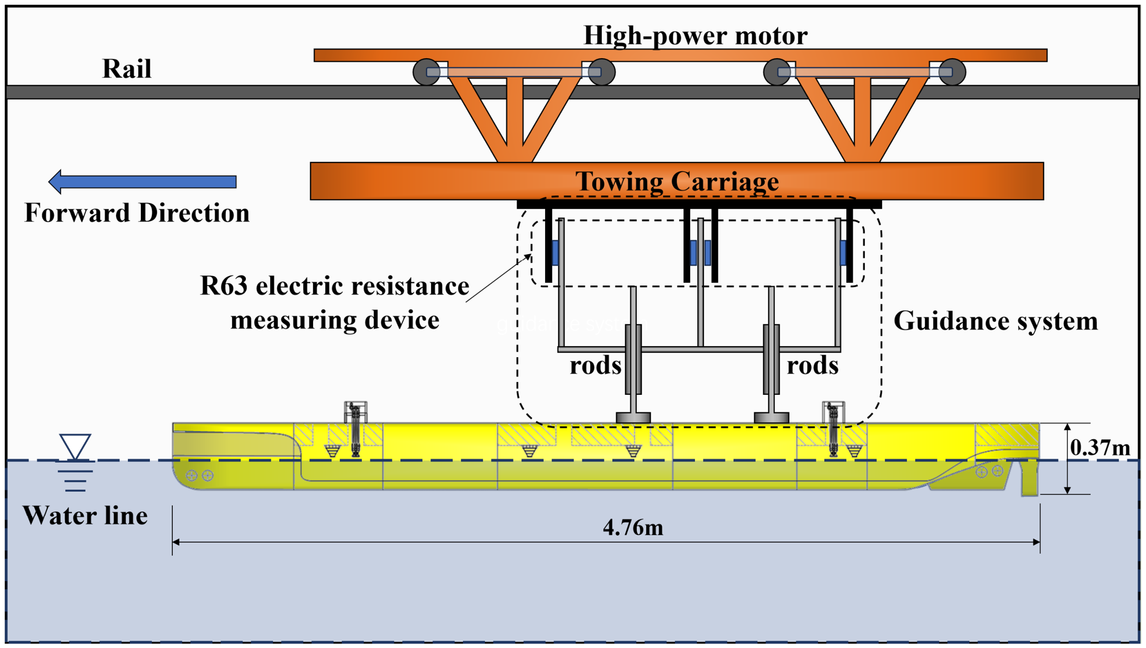
To clarify the resistance characteristics of the catamaran transporting an immersed tunnel element, resistance tests are conducted in this study. The laboratory investigations were carried out in a towing tank, which has a length of 474 m, a width of 14 m and a maximum water depth of 7.0 m. The resistance test was conducted in accordance with the Recommended Procedures and Guidelines of the International Towing Tank Conference (ITTC) for marine vehicle testing, specifically referencing Resistance Section 7.5-02-02-01 (ITTC, 2021). The detailed experimental setup of the catamaran–tunnel system is illustrated in Figure 4, along with the schematic diagram of the towing equipment. During the tests, the towing carriage was equipped with a closed-loop controlled system and a high-power motor, which enabled both constant-speed and variable-speed towing to simulate the dynamic behavior of ships under different operational conditions. The maximum speed of the towing carriage is 2.0 m/s, whereas the resistance experiments were conducted at a maximum towing speed of 0.98 m/s, ensuring the error is limited to within 0.1%. And more importantly, a guidance system, composed of two sets of rods at the bow and the stern of the catamaran model, is suspended from the carriage and connected to the catamaran model. Additionally, it should be noted that, regarding the catamaran–tunnel resistance tests, the catamaran and tunnel were rigidly connected to restrict relative motions between the floating bodies. Note that the immersed tunnel segment in practical engineering is semi-rigidly connected via supporting saddles and lifting cables to minimize relative motion, which reveals that potential relative motions occur. Thus, the rigid connection in this study would alter the hydrodynamic forces of the immersed-tunnel transportation and will hopefully be addressed in future studies. To measure the resistance characteristics of the catamaran and catamaran–tunnel models, the R63 electric resistance measuring device was adopted in the tests, with a maximum range of 400 N and a resolution of 0.1%.
Figure 4.
Experimental setup of the catamaran–tunnel system in the towing tank.
Considering the marine environmental conditions, the prototype operation speed in the resistance tests spanned from 2 to 12 kn for the catamaran alone, and the speed range was 2~7 kn for the catamaran–tunnel system. To comprehensively investigate the hydrodynamic performance of the sole catamaran, twenty-one distinct speeds were selected covering the range of 1.03 m/s~6.17 m/s, corresponding to the Froude number Fn = 0.0242~0.145. Regarding the catamaran–tunnel towing system, eleven speeds were chosen within the range of 1.03 m/s~3.60 m/s, corresponding to Fn = 0.0242~0.0846. The test matrix of the resistance study is tabulated in Table 2. Since the newly dredged channel was only encountered when the immersed tunnel is towed by the catamaran, the single catamaran resistance tests focused exclusively on the effects of varying water depths. In contrast, the resistance tests for the catamaran–tunnel system involve both the influence of water depth and the presence of the bank, to reflect different hydrodynamic environments during the towing operation of the tunnel element. To assess experimental repeatability, the first selected speed condition for the planning hull was repeated five times. The resistance measurements showed a deviation of approximately 3%, indicating a favorable level of repeatability. Note that all tests were conducted in calm water to eliminate the influence of waves and ensure that the results accurately reflect the fluid dynamic characteristics of the hull at various speeds.
To ensure the reliability of the test results, measurement uncertainties were evaluated in accordance with the procedures recommended by the International Towing Tank Conference (ITTC) Recommended Procedure 7.5-02-01-01. The potential error sources were quantified, including force transducer calibration, zero drift, carriage speed error, water property fluctuation, model draught and displacement deviation, model alignment error, data acquisition noise, and test repeatability. The individual relative uncertainties of each component are listed in Table 3. Then the root-sum-square (RSS) method was adopted for uncertainty synthesis. The combined relative standard uncertainty for resistance measurement is 3.18%, and the expanded total uncertainty (95% confidence) reaches 6.36%.
Table 3.
Individual uncertainty components for resistance measurement in this study.
3. Results
3.1. Confined Water Effects on the Total Resistance Force
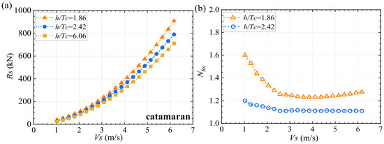
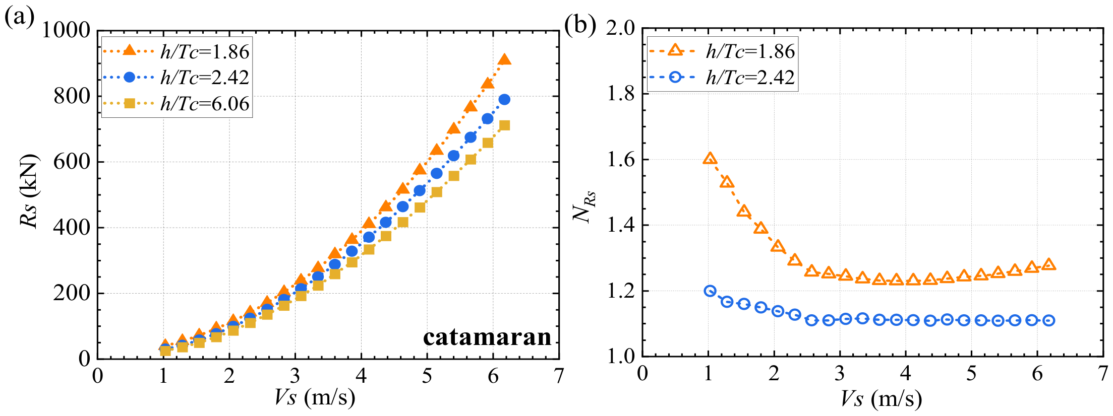
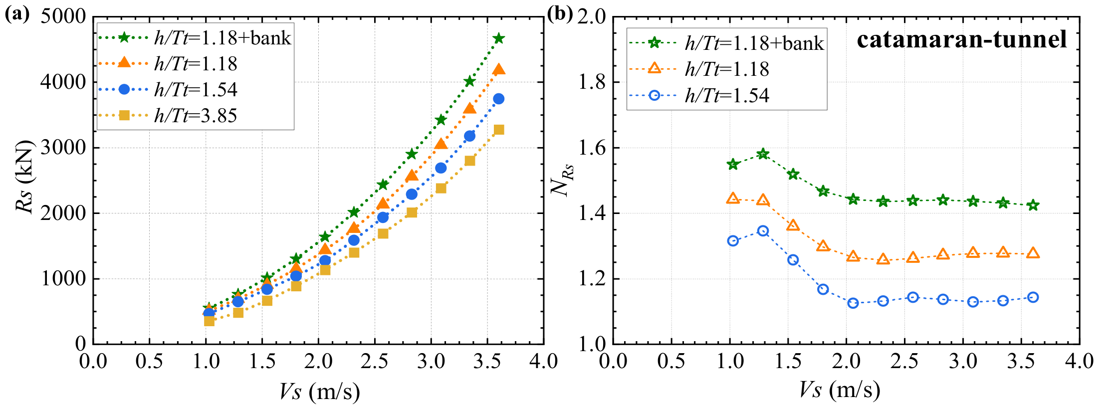
The resistance forces of the sole catamaran and the catamaran–tunnel system are included in Figure 5 and Figure 6 for various water depths from 40 m to 12.3 m. Moreover, to elaborate on the shallow-water effect, a dimensionless confined water effect ratio NR = Rs/Rs0 is introduced and plotted, where Rs0 and Rs denote the full-scale total resistance force for the least-confined condition and for the shallower water depth, respectively. Herein, h presents the still-water depth of the towing tank and Tc the catamaran draft which is the draft of the twin hulls of the isolated catamaran.
Figure 5.
The total resistance force of the sole catamaran (Vs = 1.03~6.17 m/s) (a) total resistance force; (b) confined water effect ratio.
Figure 6.
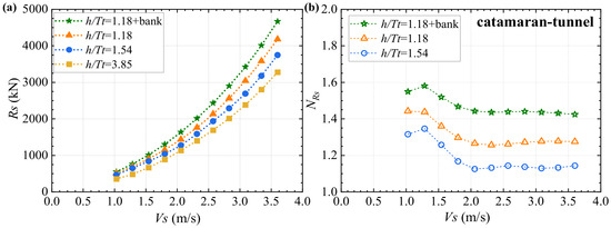
The total resistance force of the catamaran–tunnel system (Vs = 1.03~3.60 m/s): (a) total resistance force; (b) confined water effect ratio.
From Figure 5a and Figure 6a, the total resistance force of both the catamaran and catamaran–tunnel system has a distinct parabolic dependence on forward speed across all water depths, with the rate of increase accelerating at higher velocities. This trend stems from the quadratic relationship between resistance and speed, which is consistent with the results of Wu et al. [9]. Most importantly, this enhancement is significantly amplified by the shallow-water effect. Taking the catamaran as an example, the resistance enhancement manifests as a 20% increase in total resistance when water depth decreases from h/Tc = 6.06 to 2.42, and an enhancement of 60% for h/Tc = 1.86. This could be attributed to the fact that when the under-keel clearance (UKC) diminishes further from 1.42Tc (h = 16.0 m) to 0.86Tc (h = 12.3 m), compared with the UKC = 5.06Tc for h = 40.0 m, the squeezing of water between the catamaran and seabed alters the ambient pressure distribution and modifies the ship resistance, denoting the shallow-water effect [16].
Comparing the results in Figure 5 and Figure 6, it is noteworthy that the resistance of the catamaran–tunnel system is substantially higher than that of the sole catamaran, and this disparity escalates with increasing forward speed. For instance, for the water depth of h = 16.0 m, the entire towing system reaches a resistance of 12.57~15.57 times that of the sole catamaran for a wide speed range of 1.03 m/s to 3.60 m/s. This growth in towing resistance originates from two primary physical mechanisms. On one hand, the low-freeboard tunnel element leads to an enlarged wet surface area and greater draft, which exacerbates channel blockage and the local non-uniformity of the pressure build-up as reported by Ji et al. [22]. On the other hand, strong hydrodynamic coupling arises between the catamaran and submerged tunnel. Flow through gaps between the catamaran and tunnel accelerates locally, interacting with the shallow-water effect and redistributing the pressure field around the multi-body system. Unlike an isolated hull, this interference alters the critical water-depth ratio for abrupt resistance growth. Thus, conventional single-body shallow-water and bank-effect formulations cannot capture such multi-body interactions.
Furthermore, the introduction of bank constraint at h/Tt = 1.18 results in an additional resistance enhancement of 7.4~14.2% compared to the flat-bottom condition of h/Tt = 3.85 over the whole test range of forward speed. This phenomenon is consistent with the bank effect reported in [23], and can be explained by the fact that as the assembly travels along the narrow channel, the effective flow area is constricted simultaneously by limited water depth and vertical side banks. This flow constriction would accelerate the oncoming current upstream of the assembly and generate a high-pressure stagnation region at the bow. This leads to low-pressure zones both around the sides and undersides, amplifying the fore-aft pressure difference across the assembly, significantly raising the resistance.
Regarding the confined effect ratio, the variation curves in Figure 5b and Figure 6b share a similar trend, which initially declines as the forward speed increases and stabilizes beyond Vs = 3.08 m/s and 2.06 m/s for the catamaran and catamaran–tunnel system, respectively. This deviation demonstrates the significant influence of the multi-body interference on the towing resistance. This can be partly derived from the fact that the relative proportion of additional shallow-water resistance diminishes with the rising baseline resistance in deep water of h/Tc = 6.06. Although the relative shallow-water effect turns moderate in the high-speed regime, the absolute growth in total resistance remains substantial and the resistance gap is continuously widened for higher forward speed, which warrants significant attention.
3.2. Effects of the Tunnel–Catamaran Interaction on the Total Resistance Coefficients
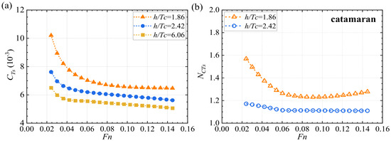
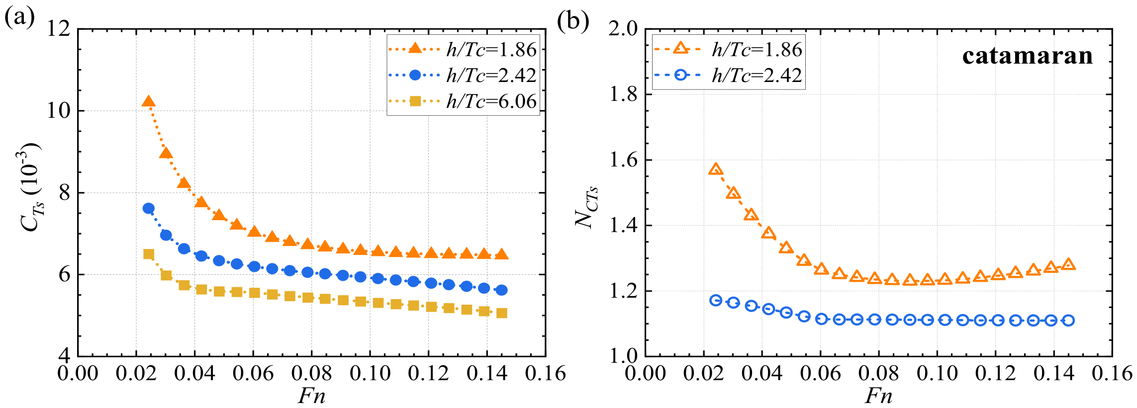
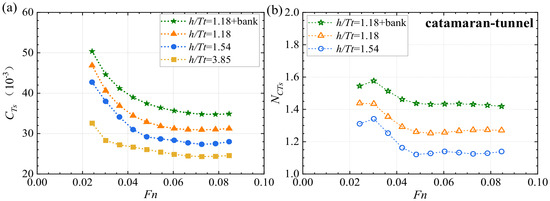
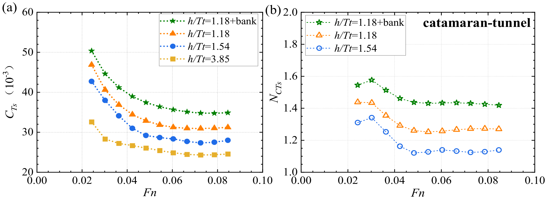
To further elaborate on the combined effects of shallow water and bank boundary, a non-dimensional analysis is performed to examine the total resistance coefficients CTs and the residual resistance coefficient CRs, following the two-factor method of Froude similarity criterion as presented in Appendix A. Figure 7 and Figure 8 respectively depict the total resistance coefficients for the sole catamaran and catamaran–tunnel system against Fn. Meanwhile, the confined water effect ratio for the total resistance coefficients is plotted in Figure 7b and Figure 8b, which is calculated by NCTs = CTs/CTs0, where CTs and CTs0 denote the total resistance coefficients for shallow-water conditions and water depth of h/Tc = 6.06, respectively.
Figure 7.
The total resistance coefficient of the sole catamaran (Fn = 0.0242~0.145): (a) total resistance coefficient; (b) confined water effect ratio.
Figure 8.
The total resistance coefficient of the catamaran–tunnel system (Fn = 0.0242~0.0846): (a) total resistance coefficient; (b) confined water effect ratio.
From Figure 7a and Figure 8a, the first thing worth noting is that the increase in Froude number for both the catamaran and the catamaran–tunnel assembly results in a continuous decline in the total resistance coefficient. This decreasing trend slows down with a rising Froude number and remains in a slight decline beyond 0.085 for the catamaran and 0.066 for the assembly. This downward tendency arises mainly because the growth of total resistance with the Froude number proceeds more slowly than the quadratic scaling with velocity, as the total resistance coefficient varies with shallow-water conditions, as reported by [16,24]. Meanwhile, in the high Fn regime, the total coefficients exhibit a relatively stable discrepancy among varying water depths, which indicates that the shallow-water effect is primarily driven by the depth-to-draft ratio rather than the vessel speed. Notably, the shallow-water effect exerts a substantial influence on the total resistance coefficients, leading to significant growth in the shallow effect ratio in Figure 7b and Figure 8b. For instance, the reduction in water depth amplifies the total resistance coefficient, yielding shallow effect ratios of 1.27~1.44 for the water depth of h/Tt = 1.18, and 1.13~1.33 for h/Tt = 1.54. Furthermore, the total resistance coefficient has a remarkable sensitivity to the bank effect across the entire test range, resulting in an additional enhancement of 7.4~14.0%.
Furthermore, compared to the sole catamaran scenarios, the presence of the towed tunnel has a profound influence on the total resistance coefficients. In the least-confined water condition of h/Tt = 3.58, the total resistance coefficients for the catamaran–tunnel system are enlarged by 5.01~4.43 times the sole catamaran, with Fn increasing from 0.024 to 0.085. This phenomenon can be attributed to the significant hydrodynamic interference between the tunnel and catamaran, which is believed to be a main cause of the increased total resistance [24]. As water depth decreases, the total resistance coefficients for the integrated towing system are enhanced to 5.61~4.51 times that of the sole catamaran for h/Tt = 1.54, yet decline to 4.69~4.40 times the sole catamaran for h/Tt = 1.18. The non-monotonic variation in resistance amplification by the coupled tunnel under high-blockage conditions can be physically interpreted by the competing flow-field reconstruction mechanism reported by Ji et al. [22], where extreme geometric confinement modifies the pressure distribution and introduces stronger lift forces, thus altering the fore-aft pressure difference across bluff tunnel structures.
3.3. Effects of the Tunnel–Catamaran Interaction on the Residual Resistance Coefficients
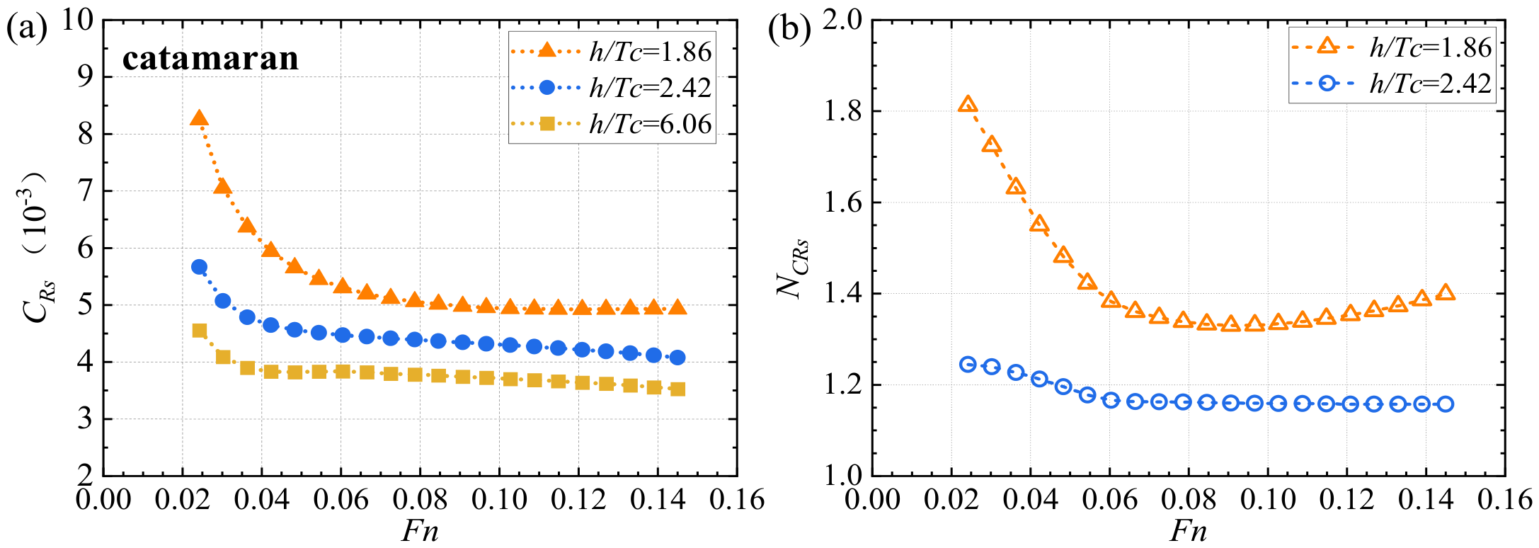
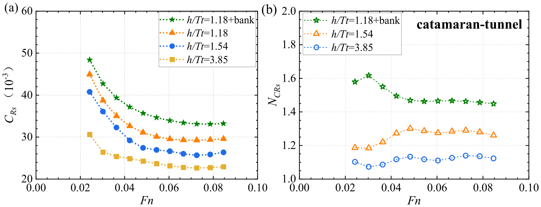
Meanwhile, the confined water effect ratio for the residual resistance coefficients for the catamaran and catamaran–tunnel assembly are plotted in Figure 9 and Figure 10, respectively, which is calculated by NCRs = CRs/CRs0, where CRs denote the residual resistance coefficients for shallow-water conditions, and CRs0 for water depth of h/Tc = 6.06, respectively. Interestingly, a comparison between the total and residual resistance coefficients reveals that the residual resistance constitutes the dominant portion of the total resistance. This could be attributed to the relative water depth of h/L being relatively small, at 0.21 (L represents the ship length), in which the generated waves by the full-form catamaran are directly constrained by the water depth and this leads to a significant wave-making resistance [17]. Furthermore, the shallow-water effect has a significant impact on the allocation share of the total resistance. As the water depth decreases from h/Tc = 6.06, the proportion of the catamaran’s residual resistance increases to 72.0~74.4% for h/Tc = 2.42 and further to 75.3~80.9% for h/Tc = 1.86. This confirms the growing dominance of the residual-resistance coefficient under shallow-water conditions, which is mainly ascribed to the findings by Duman et al. [25] that the shallow-water effect lies in the significant enhancement in the wave-making resistance and viscous pressure resistance, but makes no noticeable difference in the friction resistance. Regarding the catamaran–tunnel assembly, the residual resistance coefficient plays an even more dominant role, constituting an exceptionally high proportion of 93–96%. This phenomenon could be ascribed to the hydrodynamic interference introduced by the tunnel element, which alters flow patterns and surface pressure distribution, thereby aggregating both wave-making and viscous resistances [18]. Unlike the standalone catamaran, the integrated catamaran–tunnel is subjected to superimposed disturbances originating from three sources: free-surface wave generation, viscous flow separation around the blunt tunnel geometry, and gap-induced pressure jumps within narrow gaps between the catamaran, tunnel and channel bed. In addition, all these pressure-governed effects are collectively lumped into the residual-resistance coefficient according to standard ITTC decomposition, which explains its overwhelming share in total resistance for this multi-body towing scenario.
Figure 9.
The residual resistance coefficient of the sole catamaran (Fn = 0.0242~0.145) (a) residual resistance coefficient; (b) confined water effect ratio.
Figure 10.
The residual resistance coefficient of the catamaran–tunnel system (Fn = 0.0242~0.0846): (a) residual resistance coefficient; (b) confined water effect ratio.
4. Discussions
4.1. Formula Fitting for the Confined Water Effects
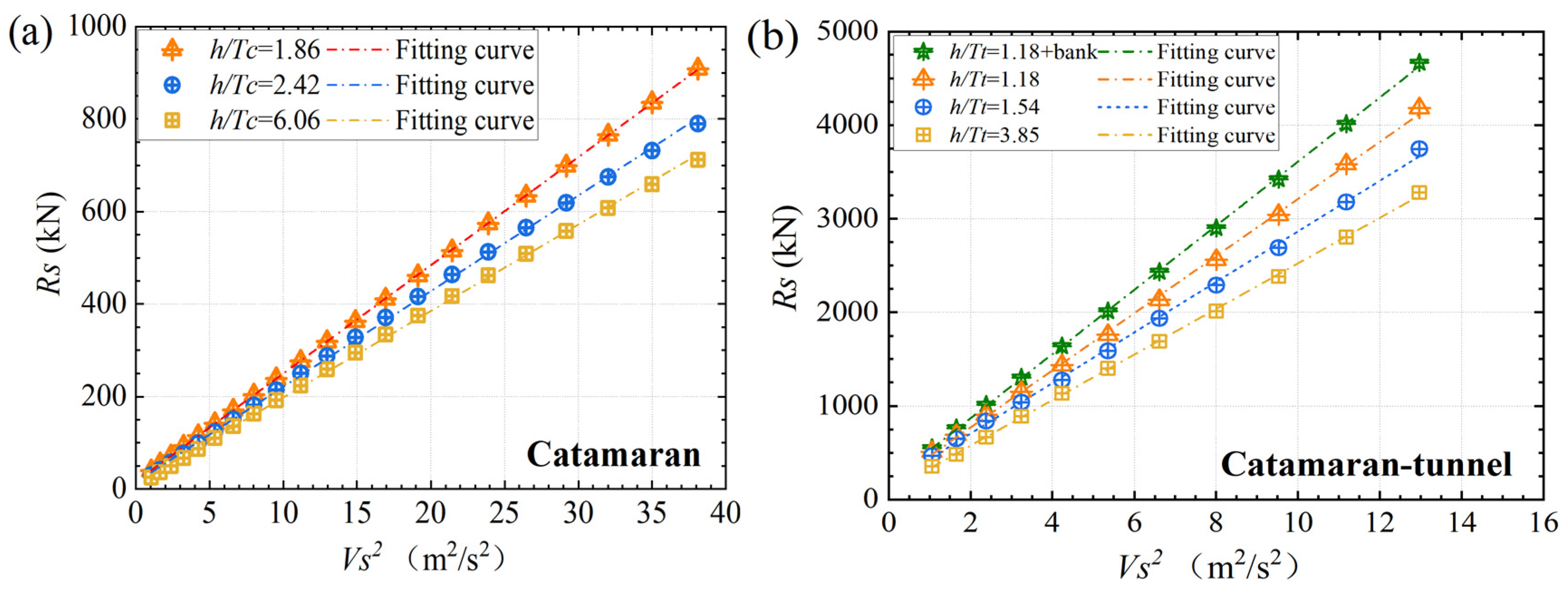
To quantify the combined effects of the shallow-water effect and bank effect on the catamaran and catamaran–tunnel towing assembly, the fitted formula of the total resistance force are derived in the following Equations (2) and (3) and presented in Figure 11.
Note that these two power-law formulations are physically motivated rather than products of blind statistical regression: every independent variable is selected from established governing parameters in confined-water hydrodynamics, aligned with prior experimental and numerical findings. The quadratic dependence on the advancing speed Vs is introduced since the residual resistance is dominated by inertial flow effects, as demonstrated by Duman et al. [25]. The wetted surface areas Sc (for the standalone catamaran) and St (for the integrated catamaran–tunnel system) serve as the characteristic reference area terms to define the surface domain over which flow-induced pressure perturbations occur, which has been widely used and formally adopted in ITTC guidelines. The dimensionless draft-to-depth ratios Tc/h and Tt/h are employed as the core blockage parameters, which directly quantify the severity of bed-imposed flow constriction. In detail, the dimensionless draft-to-depth ratio rises with decreased water depth, squeezes the flow passage between the floating body and the seabed, accelerates near-body flow, and amplifies fore–aft pressure differences, acting as the dominant control on horizontal towing resistance. Note that the hull draft of the coupled catamaran–tunnel system is significantly changed by the deep-draft tunnel segment and plays a dominant role in the hull-water interaction. Thus, the tunnel’s draft Tt is applied in the resistance prediction of the towing system. Finally, the additional (1 + tan θ) term incorporated in Equation (3) accounts for the influence of channel bank-slope angle θ. In inclined-bank confined waterways, the slope angle reshapes the effective lateral flow cross-section, modulates bank-induced flow constriction, and alters gap-flow patterns as well as surface-pressure distributions around the multi-body assembly [26].
The exponent difference in the draft-to-depth ratio between 0.33 (standalone catamaran) and 0.40 (catamaran–tunnel system) reflects different sensitivities of the structure to water-depth reduction. For the standalone catamaran, shallow waters only perturb the flow around twin slender hulls, leading to the smaller exponent 0.33. For the integrated system, multi-body hydrodynamic interference between catamaran hulls and the blunt tunnel amplifies gap-flow acceleration, flow separation and pressure gradient. The superimposed flow disturbance makes residuary resistance more sensitive to the change in draft, resulting in a higher exponent of 0.40. This exponent difference physically characterizes the intensified shallow-water effect caused by multi-body coupling, rather than simply minimizing fitting residuals. Note that the above empirical correlation for the resistance is a case-specific fit valid for the present catamaran within the tested range of Vs = 1.03~6.17 m/s and h/Tc = 1.86~6.06 and for the coupled catamaran–tunnel system within the tested range of Vs = 1.03~3.60 m/s and h/Tc = 1.18~3.58. The exponents reflect the lumped nonlinear effect of seabed squeezing, pressure redistribution and wave interference under confined water, rather than a universal theoretical exponent derived from hydrodynamic governing equations.
Figure 11.
The formula fitting for the total resistance force against the square of sailing velocity: (a) catamaran; (b) catamaran–tunnel towing system.
4.2. Limitations
In this work, the combined shallow water and bank effects are quantified through experimental insights and the multi-body interference is revealed for the catamaran–tunnel towing system. Despite these contributions, the present study carries several inherent limitations that should be recognized when interpreting the results and extending the conclusions.
It should be noted that the present experimental campaign only records global towing resistance, without PIV velocity measurements or CFD computations. Therefore, direct flow-field contours and pressure distributions are unavailable for visual validation of the inferred blockage and pressure build-up phenomena. Nevertheless, the physical reasoning is supported by indirect experimental evidence from systematic towing tests, rather than purely speculative description. This includes: (1) The comparison between unladen catamaran and laden catamaran–tunnel cases isolates the multi-body couplings. The difference in resistance rise and residual coefficient variations between these two configurations serves as experimental evidence for the hydrodynamic interference between the catamaran and tunnel. (2) The significant resistance surge under varying channel confinement and water depth demonstrates the blockage and pressure build-up effect. The sudden resistance increase occurs at a lower depth-draft ratio when side banks exist, which matches the fundamental expectation of confined flow theory. (3) The non-linear, non-additive behavior of resistance increment under combined shallow-water and bank effects further supports the coupled blockage mechanism, including viscous flow separation and pressure jumps within narrow gaps, etc. Thus, the total resistance growth cannot be reconstructed by linearly superimposing individual shallow-water and bank effects. In addition, the overall hydrodynamic trends observed in this study are compared against findings from previously published experimental and numerical investigations for catamarans, inland convoys and sole tunnel segments in restricted water depths or bank conditions [16,17,18,19,20,21,22,23,24,25,26,27,28]. Owing to geometrical differences in hull form, blockage level and Froude number, only qualitative trend comparisons are conducted, rather than direct quantitative comparisons of resistance magnitudes.
Furthermore, a series of empirical correlations are developed in this study after establishing this physical understanding for engineering application. These proposed formulas are only valid to predict the resistance performance within the tested range of Vs = 1.03~6.17 m/s and h/Tc = 1.86~6.06, and the bank-effect results are specified for a specified channel configuration. Thus, their applicability in other ships and other bank configurations remains to be further verified. In addition, the present physical model tests were conducted under calm-water conditions without the consideration of full marine environmental loads such as wind, waves and currents, which would introduce discrepancies between the experimental results and practical towing conditions.
5. Conclusions
In this study, extensive towing tank tests have been performed to investigate the resistance performance of the catamaran–tunnel towing system. Distinct shallow-water and bank effects acting on both the isolated catamaran and the integrated catamaran–tunnel system are quantitatively clarified. The main conclusions are drawn as follows:
For both the standalone catamaran and the coupled catamaran–tunnel towing system, total resistance demonstrates an evident parabolic correlation with advancing speed, accompanied by an accelerated growth rate at higher speeds. Owing to the decreasing relative under-keel clearance and squeezed waters, the shallow-water effect is substantially aggravated, raising the total resistance by 58.4% for the catamaran and 44.2% for the integrated towing system. Furthermore, the bank effect induces an additional 14.2% rise, which is primarily due to the pressure jumps within narrow gaps between the catamaran, tunnel and channel bed.
The catamaran–tunnel system exhibits stronger sensitivity to shallow water than the standalone catamaran, which reaches 15.57-fold and 6.73-fold those of the isolated catamaran across the entire test range. Accordingly, the higher exponent of the draft-to-depth ratio for the towing system (0.40 vs. 0.33) is developed in the physically motivated resistance correlations. This demonstrates that the hydrodynamic interference between the catamaran and tunnel significantly alters the shallow-water dependence of the resistance performance.
Notably, the residual resistance occupies a dominant share of total resistance for both the isolated catamaran and coupled towing system, attaining 80.9% for the single catamaran and 96.0% for the coupled system in confined waterways. This can be ascribed to the fact that the shallow-water effect drastically amplifies wave resistance and viscous pressure resistance, but makes a marginal difference in the friction resistance.
For future investigations, viscous CFD simulations together with PIV and surface-pressure measurements are recommended to capture local flow structures and pressure distributions, providing direct evidence for blockage effect and multi-body interference mechanisms. Supplementary physical model tests and full-scale field observations should also be pursued to further benchmark the empirical correlations and broaden their applicable scope.
Author Contributions
Conceptualization, Y.S. and Z.S.; methodology, X.K.; formal analysis, Y.S. and Z.S.; investigation, Z.S.; data curation, X.K. and Z.S.; writing—original draft preparation, B.L. and Y.S.; writing—review and editing, Y.S.; supervision, Y.S.; project administration, B.L. and X.K.; funding acquisition, B.L. All authors have read and agreed to the published version of the manuscript.
Funding
This research was funded by the National Natural Science Foundation of China (Grant No. 52471296).
Data Availability Statement
The data that support the findings of this study are available from the corresponding author upon reasonable request.
Conflicts of Interest
Authors Bin Li and Xiaoqiang Kou were employed by the company CCCC First Harbor Engineering Company Ltd., and CCCC Tianjin Port Engineering Institute. The remaining authors declare that the research was conducted in the absence of any commercial or financial relationships that could be construed as a potential conflict of interest.
Appendix A
To further elaborate the combined effects of shallow water and bank boundary, a non-dimensional analysis is performed to examine the total resistance coefficient CTs and the residual resistance coefficient CRs, following the two-factor method of Froude similarity criterion. Typically, the total resistance coefficient of the full-scale ship CTs with a bilge keel is defined according to the 1978 ITTC, which is
where Ss is the wet surface area of the full-scale ship, and SBK is the wet surface area of the bilge keel. ΔCF the roughness allowance coefficient, is applied to account for additional friction resistance arising from the surface roughness of the full-scale ship relative to the smooth surface of the model ship, which is calculated based on the 1978 ITTC as follows:
As recommended by the 1957 ITTC (International Towing Tank Conference), the friction resistance coefficient of the full-scale ship CFs is calculated as follows:
where Rn represents the Reynolds number and is defined as follows:
where LwL denotes the waterline length, V is the forward speed and ν is the kinematic coefficient of viscosity.
Additionally, the air resistance coefficient CAA is defined as
CRs denotes the prototype residual resistance coefficient, which equals the model ship’s residual resistance coefficient as presented as follows, given the identical Froude numbers maintained between the prototype and the model. Note that for the present catamaran–tunnel assembly, the CR not only includes the wave-making resistance, but also the viscous pressure/form effects and other contributions not represented by the frictional-resistance term. However, such frictional components may not fully satisfy the Froude similarity, which constitutes a possible scale effect in the extrapolation approach.
References
- Huang, G.; Song, Y.; Sun, Z.; Zhang, N. Experimental investigation on the coupling between immersion rig and tunnel element during freeboard elimination. Ocean Eng. 2019, 186, 106068. [Google Scholar] [CrossRef] [Scilit]
- Song, Y.; Sun, Z.; Huang, G.; Chen, N.; Gao, X. An experimental investigation on the effect of the ballasting on the coupled dynamics of the tunnel immersion system. Ocean Eng. 2019, 190, 106412. [Google Scholar] [CrossRef] [Scilit]
- Zhou, X.; Sun, X.; Jiao, Y.; Zeng, B.; Tan, F.; Li, T.; Wei, P. Development and application of a new ballast water system for immersed tunnel installation: A case study of the Yuliangzhou tunnel in Xiangyang, China. Tunn. Undergr. Space Technol. 2022, 119, 104261. [Google Scholar] [CrossRef] [Scilit]
- Song, Y.; Sun, Z.; Huang, G.; Chen, N. Coupled dynamics investigation of a tunnel immersion system under beam and oblique waves. Ocean Eng. 2020, 217, 107892. [Google Scholar] [CrossRef] [Scilit]
- Song, Y.; Chen, N.; Zhang, N. Coupled motion characteristics of a large-scale tunnel element suspended by immersion rigs in the vicinity of seabed. Tunn. Undergr. Space Technol. 2021, 110, 103804. [Google Scholar] [CrossRef] [Scilit]
- Song, Y.; Qu, Y.; Chen, N.Z.; Metrikine, A.V. Effect of immersion depth on the coupled dynamics of a tunnel-rigs system in irregular waves. Tunn. Undergr. Space Technol. 2021, 115, 104068. [Google Scholar] [CrossRef] [Scilit]
- Xiao, L.F.; Yang, J.M. Experimental study on mooring, towing and installing of immersed tunnel caissons. Shanghai Jiaotong Univ. (Sci.) 2010, 15, 103–107. [Google Scholar] [CrossRef] [Scilit]
- Wu, H.; Rheem, C.K.; Chen, W.; Xu, S.; Wu, W. Experimental study on the tension of cables and motion of tunnel element for an immersed tunnel element under wind, current and wave. Int. J. Nav. Archit. Ocean Eng. 2021, 13, 889–901. [Google Scholar] [CrossRef] [Scilit]
- Wu, Z.W.; Liu, J.K.; Liu, Z.Q.; Lu, Z.R. Nonlinear wave forces on large-scale submerged tunnel element. Mar. Struct. 2016, 45, 133–156. [Google Scholar] [CrossRef] [Scilit]
- Tezdogan, T.; Demirel, Y.K.; Kellett, P.; Khorasanchi, M.; Incecik, A.; Turan, O. Full-scale unsteady RANS CFD simulations of ship behaviour and performance in head seas due to slow steaming. Ocean Eng. 2015, 97, 186–206. [Google Scholar] [CrossRef] [Scilit]
- Barrass, C. Ship Squat in Open Water and in Confined Channels; Butterworth-Heinemann: Oxford, UK, 2012; Chapter 17. [Google Scholar] [CrossRef] [Scilit] [PubMed]
- Müller, E. Analysis of the potential flow field and of ship resistance in water of finite depth. Int. Shipbuild. Prog. 1985, 32, 266–277. [Google Scholar] [CrossRef] [Scilit]
- Yao, J.X.; Zou, Z.J.; Wang, H.M. Numerical study on bank effects for a ship sailing in shallow channel. J. Shanghai Jiaotong Univ. 2011, 16, 91–96. [Google Scholar] [CrossRef] [Scilit]
- Böttner, C.U.; Anschau, P.; Shevchuk, I. Analysis of the flow conditions between the bottoms of the ship and of the waterway. Ocean Eng. 2020, 199, 107012. [Google Scholar] [CrossRef] [Scilit]
- Wang, H.Z.; Zou, Z.J. Numerical prediction of hydrodynamic forces on a ship passing through a lock. China Ocean Eng. 2014, 28, 421–432. [Google Scholar] [CrossRef] [Scilit]
- Li, M.; Chen, Y.; Yuan, Z.M.; Cheng, Y.; Tao, L. Interference effects on the upstream wave generated by the catamaran moving across a depth change. Ocean Eng. 2023, 287, 115939. [Google Scholar] [CrossRef] [Scilit]
- Du, P.; Ouahsine, A.; Sergent, P.; Hoarau, Y.; Hu, H. Investigation on resistance, squat and ship-generated waves of inland convoy passing bridge piers in a confined waterway. J. Mar. Sci. Eng. 2021, 9, 1125. [Google Scholar] [CrossRef] [Scilit]
- Wu, J.; Zeng, J.; Tang, H.; Wang, W. Experimental Study on the Drag Resistance of Tunnel Towing Navigation Facilitating Upstream and Downstream Connectivity in Mountainous River Bends. Appl. Sci. 2024, 14, 11560. [Google Scholar] [CrossRef] [Scilit]
- Mucha, P.; el Moctar, O.; Dettmann, T.; Tenzer, M. An experimental study on the effect of confined water on resistance and propulsion of an inland waterway ship. Ocean Eng. 2018, 167, 11–22. [Google Scholar] [CrossRef] [Scilit]
- Elsherbiny, K.; Tezdogan, T.; Kotb, M.; Incecik, A.; Day, S. Experimental analysis of the squat of ships advancing through the New Suez Canal. Ocean Eng. 2019, 178, 331–344. [Google Scholar] [CrossRef] [Scilit]
- Liu, H.; Ma, N.; Gu, X. Experimental study on ship-bank interaction of very large crude carrier in shallow water. Shanghai Jiaotong Univ. (Sci.) 2018, 23, 730–739. [Google Scholar] [CrossRef] [Scilit]
- Ji, T.; Yang, Y.; Zhang, W.; Yu, P.; Chen, J.; Yu, L.; Li, J. Hydrodynamic characteristics during floating and installation of high blockage-ratio immersed tunnels in Inland Rivers. Sci. Rep. 2026. [Google Scholar] [CrossRef] [Scilit]
- Shi, G.; Priftis, A.; Xing-Kaeding, Y.; Boulougouris, E.; Papanikolaou, A.D.; Wang, H.; Symonds, G. Numerical investigation of the resistance of a zero-emission full-scale fast catamaran in shallow water. J. Mar. Sci. Eng. 2021, 9, 563. [Google Scholar] [CrossRef] [Scilit]
- Jebin Samuvel, T.; Vijayakumar, R. Impact of Water Depth on the Resistance of a Mini-Bulk Carrier: An Experimental and Numerical Study. J. Mar. Sci. Appl. 2025, 24, 1174–1193. [Google Scholar] [CrossRef] [Scilit]
- Duman, S.; Boulougouris, E.; Aung, M.Z.; Xu, X.; Nazemian, A. Numerical evaluation of the wave-making resistance of a zero-emission fast passenger ferry operating in shallow water by using the double-body approach. J. Mar. Sci. Eng. 2023, 11, 187. [Google Scholar] [CrossRef] [Scilit]
- Luo, W.; Yang, B.; Sun, Y. Hydrodynamic analysis of KVLCC2 ship sailing near inclined banks. Math. Probl. Eng. 2021, 2021, 6655971. [Google Scholar] [CrossRef] [Scilit]
- Ulgen, K.; Dhanak, M.R. Hydrodynamic performance of a catamaran in shallow waters. J. Mar. Sci. Eng. 2022, 10, 1169. [Google Scholar] [CrossRef] [Scilit]
- Martić, I.; Degiuli, N.; Borčić, K.; Grlj, C.G. Numerical assessment of the resistance of a solar catamaran in shallow water. J. Mar. Sci. Eng. 2023, 11, 1706. [Google Scholar] [CrossRef] [Scilit]

Disclaimer/Publisher’s Note: The statements, opinions and data contained in all publications are solely those of the individual author(s) and contributor(s) and not of MDPI and/or the editor(s). MDPI and/or the editor(s) disclaim responsibility for any injury to people or property resulting from any ideas, methods, instructions or products referred to in the content. |
© 2026 by the authors. Licensee MDPI, Basel, Switzerland. This article is an open access article distributed under the terms and conditions of the Creative Commons Attribution (CC BY) license.