


Abstract
In harsh marine environments, during the operation of the Ship–Cable–Body coupled system, the towed cable may become slack or taut, and tension oscillations may occur, leading to cable breakage or launch and recovery system (LARS) damage, underscoring the need for effective compensation control. Traditional offline and static simulation methods fail to capture the system’s dynamics, leading to inaccurate validation of control strategies. To address this, we propose a real-time dynamic modeling framework using the OrcFxAPI, enabling millisecond-level bidirectional interaction between the towed body’s motion and LARS commands. By integrating a Python 3.10-based PID controller with OrcFxAPI, the framework achieves real-time active heave compensation (AHC) in deep-sea towing, dynamically adjusting cable length and payout speed based on feedback to suppress vibrations. Unlike prior studies focused on launch and recovery, this work systematically evaluates AHC performance during typical operations (hovering, linear and turning motion), and compares system responses with and without compensation. Results show the AHC framework significantly improves towed body stability, reduces tension fluctuations, and keeps tension within safe working limits (SWLs), while identifying critical cable payout speed thresholds for practical operation. The approach validates the use of OrcFxAPI for high-fidelity real-time coupling analysis and provides a reliable tool for optimizing control and design of deep-sea towing systems.
1. Introduction
When an underwater towed system is operating in the complex and variable marine environment, the towing ship will generate six-degree-of-freedom (6-DoF) oscillation movements around its original equilibrium position, including surge, sway, heave, roll, pitch and yaw. These motions cause position fluctuations in the towed body, and the towed cable is repeatedly impacted by variable tension. Among the 6-DoF movements, heave motion has a more significant impact on the system (including the position of the towed body and the tension of the towed cable) than other movements [1,2]. Under severe sea conditions, the cable undergoes repeated bending, deformation, and high-tension periods when launching and recovering the towed body, which may lead to cable damage or breakage. Besides severe sea conditions, the operational safety of the towed body is also affected by the physical elasticity of the long cable. The physical elasticity of the long cable usually amplifies the ship’s heave motion, resulting in a greater heave motion of the towed body, with a certain time delay. Therefore, the drastic changes in the position of the towed body and the tension of the tow cable not only compromise sensor measurements but also threaten the towing system’s operational safety. To address these challenges, heave compensation technology has been developed and widely applied in offshore operations, including deep-sea exploration, salvage, and oil and gas extraction [3].
The main function of the heave compensation system is to reduce the vibration of the towed body and prevent the tension slack of the umbilical cable during offshore operations. Based on power supply modes, heave compensation systems can be categorized into active, passive, and semi-active compensation systems. Active compensation systems (AHC), despite their complex structures and control algorithms, are widely employed in deep-sea equipment due to their high compensation efficiency, which can reach up to 95% [4]. Relevant studies have focused on offshore lifting and drilling scenarios. Sun et al. [5] developed a simulation model for a heave compensation system using a genetic PID control algorithm to reduce the negative impact of unexpected heave movements during offshore lifting operations. The results showed that the control method enhanced the stability and rapidity of the system, ensuring effective heave compensation. Zhang et al. [6] proposed a PID-DDPG hybrid control method to control the wave compensation platform, simulated ship heave motion under four sea conditions and compared it with PID and DDPG methods. The results showed that the hybrid control method achieved compensation efficiencies exceeding 99%, effectively addressing challenges such as wind blade installation under wave fluctuations. Huang et al. [7] designed a new semi-active heave compensation system through structural design, system modeling and internal model PID robust displacement controller design, which simplified the structure of the offshore drilling heave compensation system and reduced the energy consumption of the AHC system. These studies confirm that AHC technology has matured in static or low-dynamic offshore operations [8].
However, the application of AHC technology to underwater towing scenarios remains in its infancy. Unlike offshore lifting and drilling (static/low-dynamic processes with core objectives of fixed-point hoisting or constant drilling pressure), deep-sea towing involves dynamic following and must simultaneously address the strong coupling effect of long-cable elastic amplification and ship heave motion. Existing research mainly focuses on the launch and recovery of towed bodies, neglecting dynamic responses under typical towing conditions and the key issue of ship heave motion amplification by long cables. This research gap highlights the urgent need for targeted AHC solutions for dynamic towing operations.
For the coupled modeling of the Ship–Cable–Body system, there are mainly three approaches: theoretical analytical methods, numerical simulation and experimental research. Experimental research on towed systems is rarely conducted due to its high cost, though notable exceptions exist. For example, Johansen et al. [9] obtained valuable experimental data on cable dynamics. Numerical simulation, by contrast, has been widely adopted and validated. Ablow et al. [10] developed a model based on the finite element method and solved it numerically using the finite difference method, which was capable of calculating the motion of the towed system under most operating conditions. Htun et al. [11] proposed a mixed formulation, which was fully based on absolute coordinates, to model underwater tethered vehicle systems, effectively capturing the highly coupled dynamics between the interconnected rigid and non-flexible bodies. Lubis et al. [12] measured the snap-induced tension in the umbilical cable during launch and recovery processes using OrcaFlex (version 11.3). By analyzing the results under various wave conditions and underwater depths, they developed a simplified numerical model of a floating ROV operating in the splash zone. Zhao et al. [13] established a fully coupled numerical model using OrcaFlex to explore the capacity of the ROV in an autonomous offshore intervention system. Sarda et al. [14] described a conceptual design for the automatic launch and recovery (L&R) of an AUV from an USV, and modeled the L&R process in OrcaFlex to assess its feasibility and conduct parametric studies to support the development of the best operating procedures for the launch and recovery system (LARS). Bashir et al. [15] presented a method for predicting ROV response in the transition through the wave-affected splash zone during launch or recovery. Further modelling of the ROV has been completed using OrcaFlex, to validate the predicted hydrodynamic coefficients obtained from the experimental measurements. In summary, the method of modeling the coupled system through OrcaFlex has been quite mature. Notably, OrcaFlex supports external program import, enabling the introduction of heave compensation systems in combination with control algorithms. This method can predict the configuration of the towing system during movement, which is of great significance for grasping the movement laws and characteristics of the towed system and also holds significant reference value for the safe operation of the towed system.
Nevertheless, existing AHC studies rarely employ real-time bidirectional coupling between control commands and hydrodynamic simulations. Most adopt offline or one-way coupling methods, limiting their ability to capture the nonlinear interactions between cable elasticity, ship motion, and control execution, particularly under dynamic towing conditions. As a result, how real-time compensation commands influence towing depth, tension stability, and system safety remains largely unexplored in the literature.
Furthermore, practical AHC systems typically rely on a two-stage actuation architecture, where a main winch handles large-stroke deployment and a secondary winch provides the high-bandwidth motion necessary for vibration suppression [3,16,17,18]. To avoid hardware-specific assumptions and retain focus on the coupling mechanism rather than equipment design, the present study models the actuation interface as an ideal, speed-controllable boundary actuator that is functionally equivalent to the high-bandwidth compensation unit used in real systems. This ensures that the compensation actions applied in the simulation reflect the bandwidth required to suppress dynamic disturbances, without introducing the mechanical limitations of a main winch.
To fill the aforementioned research gap, this study proposes a fully coupled, simulation-based AHC framework integrating Python-PID with OrcaFxAPI. Specifically, the cable is modeled via the lumped mass method, and the towed body’s hydrodynamic state is described by Gertler and Hagen’s [19] 6-DoF motion equation. OrcaFlex constructs the Ship–Cable–Body coupled dynamic simulation environment, while a Python-developed PID control algorithm is deeply integrated with OrcaFxAPI to establish a 10 ms-level real-time bidirectional interaction mechanism. This millisecond-level bidirectional interaction breaks the limitation of disjointed control logic and dynamic models in traditional simulations, enabling synchronous reading of key dynamic parameters and closed-loop feedback of control commands to align with engineering practice. Additionally, the PID output dynamically adapts the cable’s boundary conditions, addressing the inaccuracy of fixed boundary assumptions in conventional simulations. Focusing on the integration of mature PID control with a professional dynamic simulation platform (rather than breakthroughs in control theory itself), this study aims to realize real-time AHC for dynamic towing systems, reveal the critical threshold of cable retraction/deployment speed, and provide technical support for practical engineering applications.
2. Establishment of Towing System Dynamic Model
2.1. Model Illustration
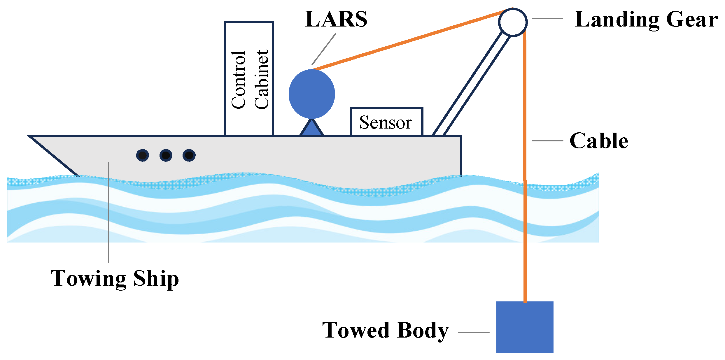
Underwater towing systems are widely employed in underwater target detection, biological sampling, and marine salvage and rescue, etc. Generally, they are composed of a towing ship, launch and recovery system (LARS), launching gear, towed cable (umbilical cable), and towed body. The schematic diagram of the system is presented in Figure 1.
Figure 1.
Underwater towed system.
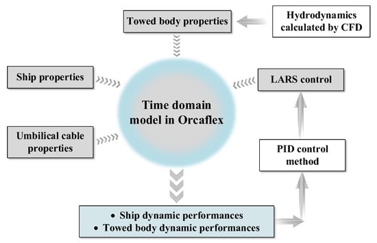
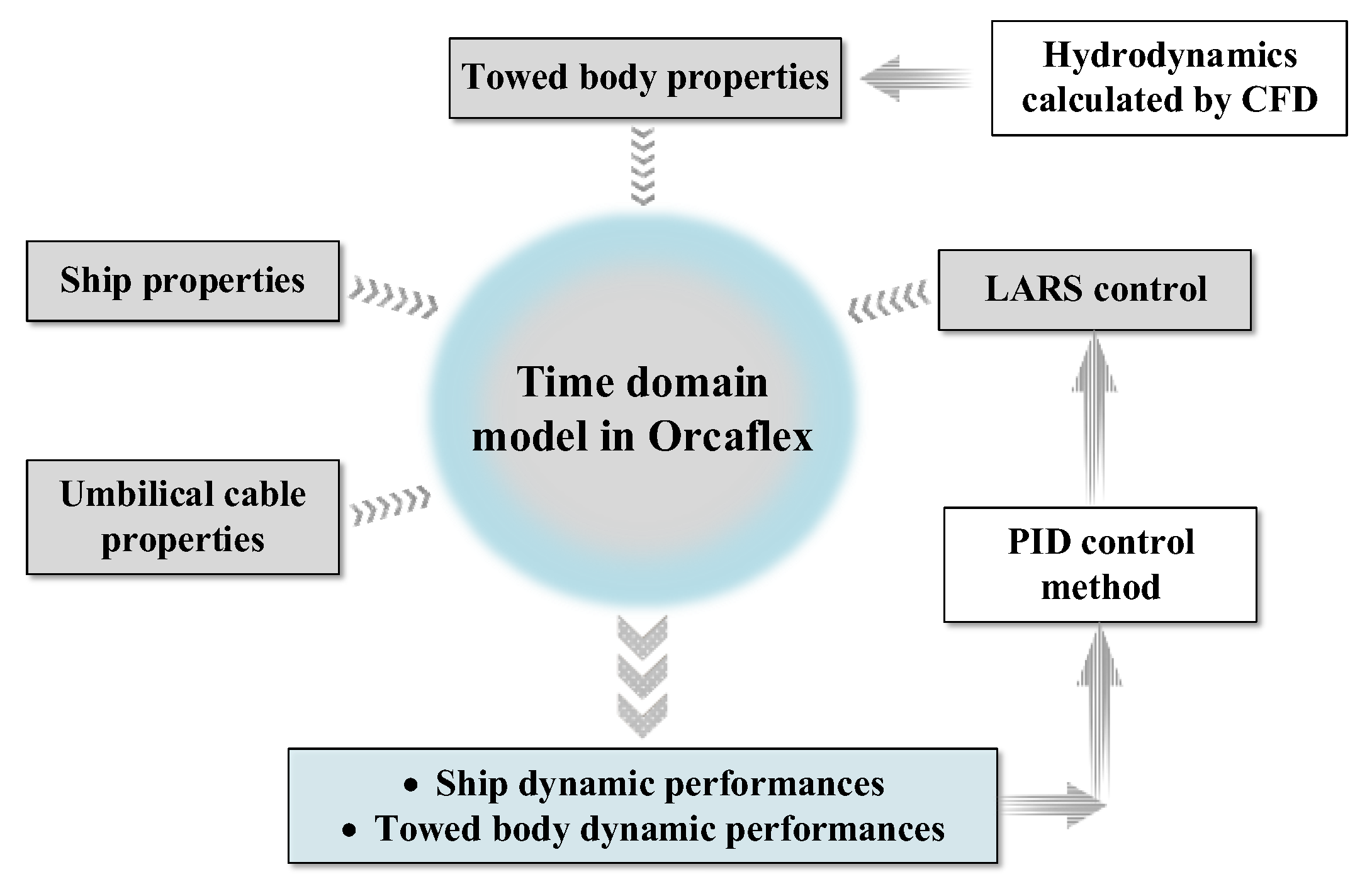
Figure 2 provides an overview of the modeling scope. The numerical simulation includes CFD calculations and time domain simulations. The hydrodynamic force of the towed body is obtained through Star-CCM+. In all simulations, the motion of the ship is considered, and modeled by defining the 6-DoF RAOs (Response Amplitude Operator) of the ship (see Orcina 2019 [20] for further information). The physical properties of the towed body and the umbilical cable are implemented in a fully coupled nonlinear hydrodynamic time domain model, to estimate the responses and forces imposed on the ship, the towed body, and the umbilical cable. A PID control method is adopted by Python code and integrated into the model through the OrcFxAPI to provide heave compensation force, control the length and speed of the LARS, and stabilize the towing system.
Figure 2.
The overview of the numerical model.
In this paper, a numerical model is developed using OrcaFlex to estimate the responses and forces endured by the towing ship, towed body, and umbilical cable. To simplify the model while maintaining accuracy.
The hydrodynamic analysis of OrcaFlex consists of static and dynamic phases. In this study, the static analysis mainly serves two purposes: (1) to determine whether the system structure achieves static equilibrium under the influence of gravity, buoyancy, and viscous forces of water flow; (2) to provide a stable initial state for the subsequent dynamic analysis. The dynamic analysis begins from the equilibrium configuration obtained in the static analysis and includes the self-building phase and the holding analysis phase. The self-building phase refers to the process where wave excitation and ship motion are gradually loaded from zero to the target value, usually lasting for one wavelength to ensure a smooth transition of the system to the steady-state response. After the self-building phase is completed, the model enters the holding analysis phase to conduct effective data collection and response assessment.
Dynamic simulation employs both explicit and implicit numerical methods to update the system’s geometric configuration at each time step, fully considering the geometric nonlinearity effects and the spatial distribution characteristics of wave loads and other factors. The motion equations are solved using the fixed-step explicit forward Euler method (Euler integration), with the initial parameters determined by the static analysis. At each time step, the forces and moments acting on each free body and node are calculated, including gravity, buoyancy, hydrodynamic forces, air resistance, added mass forces, cable tension, shear force, bending moment, torque, and control forces applied by hinges and winches, etc.
2.1.1. The Towed Body
The towed body is represented as a simplified 6D buoy, with its main parameters listed in Table 1. Since the model adopted in this study is consistent with the one proposed by Jiang et al. [21], and this model has already been solved for hydrodynamic parameters using the Computational Fluid Dynamics (CFD) method in the Star-CCM+ software Version 2302 and verified through simulation to be reliable, the relevant hydrodynamic parameters can be directly cited without the need for repeated calculations.
Table 1.
Main parameters of towed body.
2.1.2. The Launch and Recovery System (LARS) and Cable
The LARS in this study refers to the functional system on board that adjusts the cable length and its deploying/retrieving speed. In practical offshore AHC systems, large-stroke cable handling is typically performed by the main winch, whereas high-bandwidth heave compensation and vibration suppression are provided by a secondary winch or active compensation unit. To avoid unnecessary hardware-specific assumptions and to focus solely on the dynamic coupling mechanism between compensation actions and towing responses, the LARS is not modeled as a main winch. Instead, it is abstracted as an ideal, speed-controllable actuator, functionally equivalent to the secondary compensation unit used in practical AHC systems. This abstraction allows the applied compensation motion to possess the bandwidth required to counteract depth fluctuation and tension oscillation without being subject to the limitations of real winch mechanics.
In the OrcaFlex simulation modeling, the above simplification is specifically reflected in the following aspects. The LARS is set as a massless object, and its core control function is realized through the winch module in the software. To accurately capture the dynamic characteristics of the underwater towing cable, the underwater part is simulated using a line (i.e., the main body of the umbilical cable), and this module fully considers the physical parameters of the towing cable (such as the safe working load, SWL) and the hydrodynamic characteristics (specific parameters are shown in Table 2), ensuring the accuracy of the core dynamic behaviors. The maximum retractable length of the cable meets the depth requirements of the target, and the length parameter is not a key variable in this study. The winch actions between the ship and the cable are regulated in real time by a PID controller through OrcFxAPI, achieving a closed-loop coupling between the retrieval speed instructions and the dynamic response of the towing system, ultimately achieving the research goal of focusing on the correlation between the compensation logic and the towing motion. This modeling treatment ensures that the focus of the study remains on revealing the relation between compensation logic and towing dynamics, rather than on the hardware configuration of the winch system.
Table 2.
Main parameters of cable.
Note that the cable launch and recovery speed assumed in this study is an idealized condition, designed to verify the framework’s dynamic response capability. Practical commercial secondary compensation systems typically operate within a speed range below 1–2 m/s [3], and the proposed framework can be directly adapted to accommodate this realistic operational envelope.
2.1.3. The Environmental Parameters
To provide a more intuitive comparison of the towed body motion with and without compensation, the environmental conditions are configured to prioritize the validation of the core research objectives. While ensuring the stability and controllability of the test scenario. Specifically, the environment is simplified to avoid interference from cross variables (e.g., nonlinear wave characteristics, complex current effects), which helps to accurately verify the feasibility of the active heave compensation method based on the OrcFxAPI, and reveal the speed thresholds for cable deployment/recovery. The detailed environmental parameters are summarized in Table 3.
Table 3.
Main parameters of wave.
The environmental conditions are based on a single deterministic Airy wave implementation. The rationale for this design and its reliability verification are detailed in Section 3.1.4.
2.1.4. The Towing Ship
The motion response of a towing ship is mainly determined by the Response Amplitude Operators (RAOs). RAOs is the key engineering parameters in the design of ships and floating bodies, essentially a transfer function between wave excitation and hull motion, used to quantify the dynamic behavior of ships in complex sea conditions. Their acquisition methods include tank model experiments, Computational Fluid Dynamics (CFD) simulations, and diffraction analysis in potential flow theory. In the OrcaFlex software, RAOs are the core input parameters for simulating the motion response of the hull; once RAOs and related hydrodynamic coefficients are determined, the dynamic motion characteristics of the hull can be obtained through time-domain simulation.
This paper builds a simulation model in OrcaFlex based on the actual main dimensions of the towing ship. The core parameters are as follows: length 100 m, breadth 16 m, depth 13.32 m, designed draft 6.66 m, displacement 1000 t, transverse metacentric radius 1.84 m, longitudinal metacentric radius 114 m, block coefficient CB = 0.804, yaw moment of inertia 5.83 × 10⁹ kg·m2. It should be noted that in this study, the RAOs, wave drift quadratic transfer functions (QTFs), added mass coefficients, and damping coefficients of the ship are all preset data from the built-in example ships in the OrcaFlex. Such data are generated by the software developers based on typical ship parameters through professional diffraction analysis, aiming to demonstrate its motion solution mechanism (see Orcina 2019 [20]), and are suitable for principal verification studies.
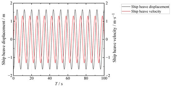
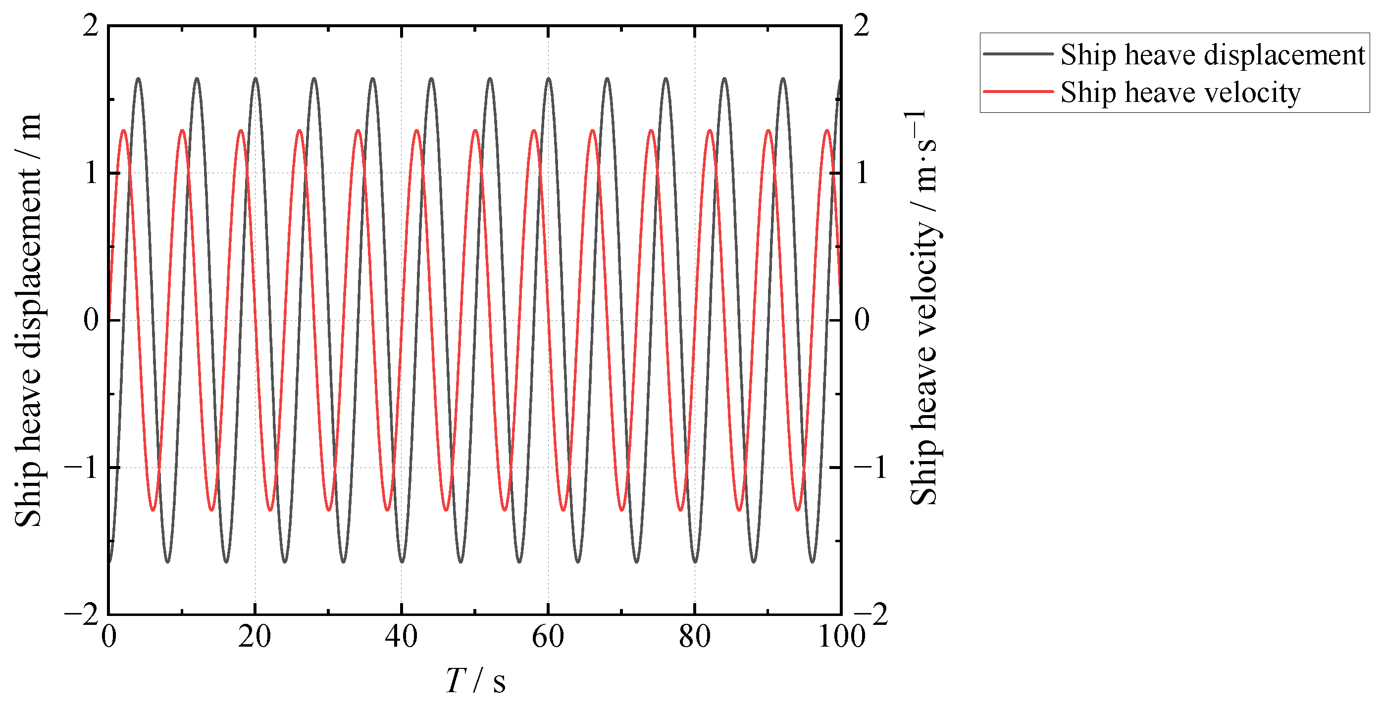
Based on the above model and the target sea conditions, time-domain simulations were conducted using OrcaFlex to obtain the key motion responses of the ship. The simulation results (as shown in Figure 3) indicate that the heave amplitude of the ship is ±1.29 m, and the heave velocity range is ±1.64 m/s, which varies dynamically with the incident wave period. This study relies on the Launch and Recovery System (LARS) technology to suppress the ship’s heave disturbance and precisely maintain the towed body at the predetermined operation position, achieving active heave compensation. This provides a clear and quantified disturbance input boundary for the subsequent design of compensation control logic.
Figure 3.
Time-domain diagram of the ship heave motion characteristics.
2.1.5. Introduction to LARS PID Control and Coupling Concept
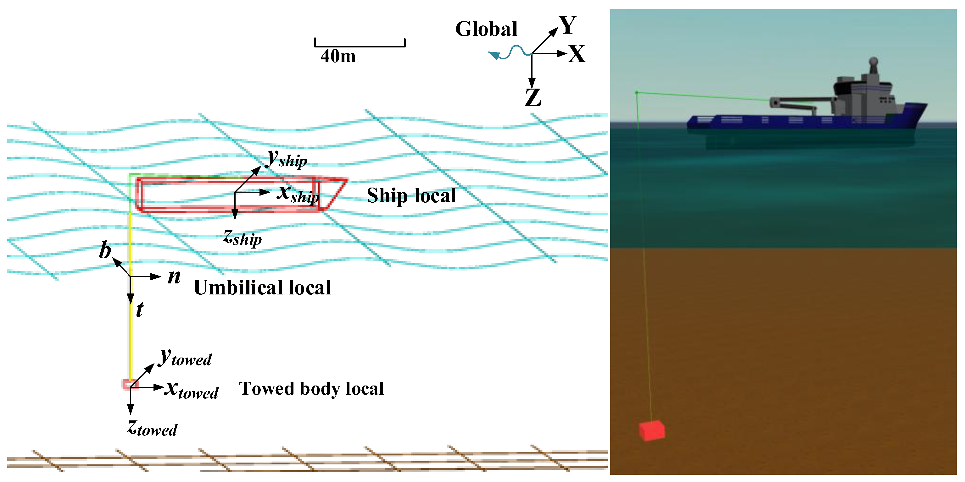
In order to control the LARS, a PID controller is adopted. This is a general control loop feedback mechanism that is widely used in control systems. The PID control algorithm is coded in Python (a dynamic scripting language) and connected to the OrcaFlex model through the OrcFxAPI. The core modeling innovation of this study lies in constructing a control-simulation deeply coupled architecture. The PID control algorithm written in Python interacts in real-time with the OrcaFlex hydrodynamic simulation software through the OrcFxAPI interface. The API interface transmits towed body position and cable tension data to the PID controller. The controller dynamically outputs cable deploying and retracting speed commands based on the deviation (difference between target position/tension and actual values), which are then fed back to the LARS model in OrcaFlex through the API, realizing a closed-loop real-time compensation process of data acquisition, control calculation and execution adjustment. Compared with the traditional method with simulation first and control later in an offline mode, this framework can synchronously complete compensation control during time-domain simulation, which is more consistent with the dynamic response requirements of towing systems in actual engineering. Figure 4 illustrates the model in Orcaflex.
Figure 4.
Model setup of the coupled time-domain model in Orcaflex.
2.2. The Coordinate System
To accurately characterize the dynamics of the Ship–Cable–Body coupled system, four coordinate systems are defined (Figure 3):
(i) The global coordinate system, with the origin at any point on the Earth’s;
(ii) The local coordinate system of the ship, with the origin located at the center of gravity of the towing ship;
(iii) The local coordinate system of the towed body, with the origin placed at the center of gravity of the towed body (xG, yG, zG);
(iv) The local coordinate system of the umbilical cable, with the origin situated at the central axis of the towed cable.
The relationship between the global coordinate and the local coordinates of the ship and body is described using Euler angles [22]. For the towed body, the Euler angles (φship, θship, ψship), which represent the rotation of the local coordinate system (xtowed, ytowed, ztowed) relative to the global coordinate system (X, Y, Z), namely the roll angle, pitch angle and yaw angle, are expressed as in Equation (1). Similarly, for the ship, the Euler angles (φship, θship, ψship) describe the rotation of the local coordinate system (xship, yship, zship) relative to the global coordinate system (X, Y, Z), are expressed as in Equation (2).
where R is the transformation matrix between the global coordinate system and the local coordinate system of the ship and body. The coordinate transformation relationship is as follows:
In the local coordinate of the cable, t is the tangent direction of the cable, and b is in the (X, Y) plane. By applying the transformation method developed by Feng and Allen [23], the local coordinate of the cable can be transformed into the global coordinate through three conversions: (a) Rotate counterclockwise around the Z-axis by an angle (α) to rotate the X-axis to the (t, n) plane; (b) Rotate counterclockwise around the new X-axis by 90 degrees to make the Z-axis coincide with the b-axis; (c) Rotate clockwise around the b-axis by β degrees to make the X and Y axes coincide with the t and n axes, respectively. Therefore, the relationship between these two coordinate systems can be expressed as:
where
2.3. Equation of the Towed Body Motion
Considering the towed body as a 6-DoF buoy, its motion can be analyzed using the force analysis and planar motion equations. The 6-DOF spatial motion equation of the towed body, described in its local coordinate system, is given by Gertler and Hargen [19]:
where [u, v, w]T and [p, q, r]T are the three-dimensional linear velocity and angular velocity of the towed body, respectively; m is the mass of the towed body; Ix, Iy and Iz are the mass moments of inertia about the principal axes, Ixy, Ixz and Iyz are the cross moments of inertia of the towed body. The right side of the equation represents the inertial force and moment of the towed body, and the left side terms F = (Xtowed, Ytowed, Ztowed) and M = (Ktowed, Mtowed, Ntowed) are the external force and moment acting on the towed body. These external forces and moments include the cable tension, the restoring force (the resultant force of gravity and buoyancy) and hydrodynamic force of the towed body, that is,
where the subscript W indicates the hydrostatic restoring force; T indicates the cable tension; H indicates the hydrodynamic force acting on the towed body.
The hydrodynamic forces and moments acting on the towed body mainly include the fluid inertial force FI, the damping force FD and the viscous force FV and the corresponding moments MI, MD, MV. For a completely submerged towed body, the expressions of each component force are written based on empirical formulas as follows:
where the first term represents the Froude-Krylov force or moment; the second term represents the added mass force; mD is the displaced mass of the towed body in each direction; ID is the inertia moment of the displaced mass in each direction; IA is the inertia moment of the added mass in each direction; Ca is the added mass coefficient in each direction; a and w are the water flow acceleration and angular acceleration relative to the global coordinate system, respectively; aR and wR are the water flow acceleration and angular acceleration relative to the towed body.
The expressions for the viscous hydrodynamic force FV and moment MV are as follows:
where ρ is the density of seawater; and respectively represent the translational force coefficient and moment coefficient of each direction component; A and AM are the force area and moment area of each direction component; vR is the speed of the towed body relative to the fluid.
In addition, the expressions for the total drag force FD and moment MD are as follows:
where FU and MU, respectively, represent the unit drag force and drag moment acting in each direction. The unit drag force and drag moment indicate the force and moment received when the relative velocity of the towed body is equal to 1 m/s.
2.4. Equation of the Umbilical Cable Motion
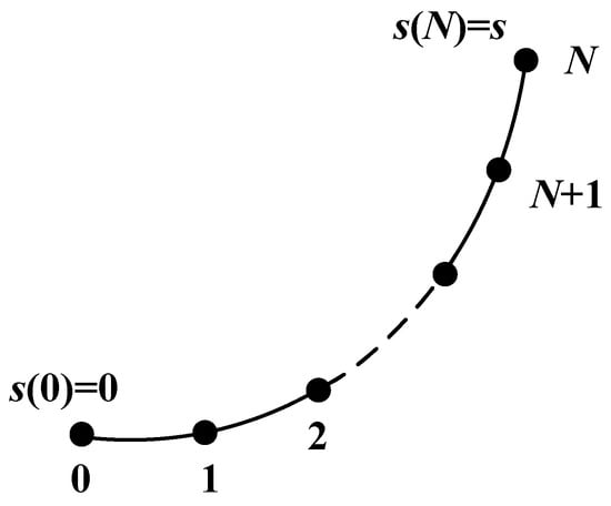
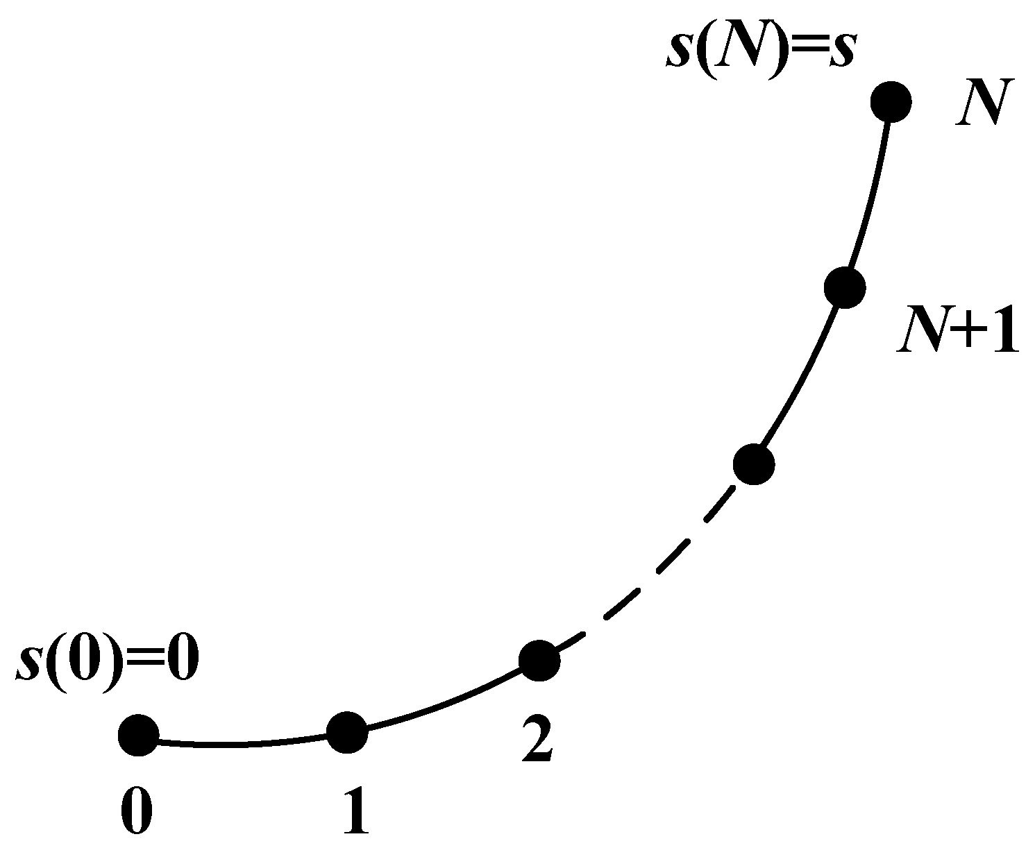
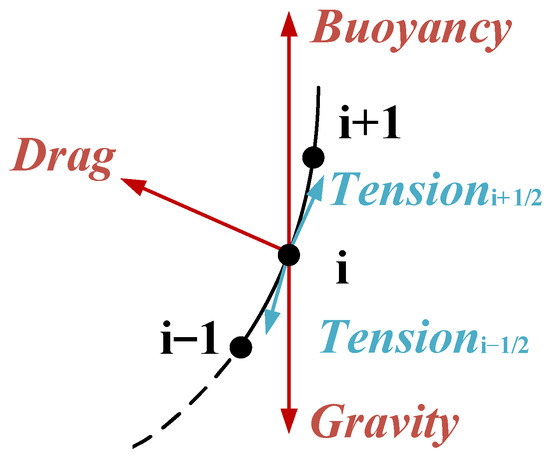
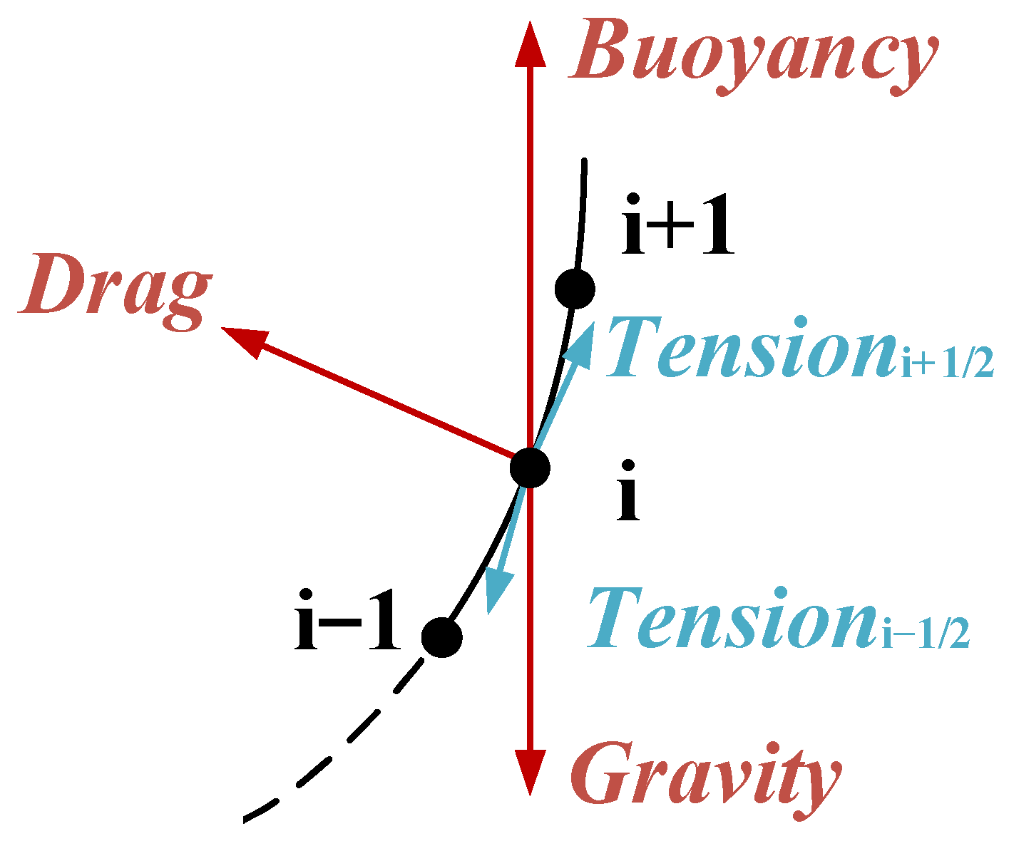
In this paper, the model of the umbilical cable is regarded as a slender and flexible cylindrical cable. A discrete lumped mass model is adopted to solve the nonlinear boundary value problem. The basic thought of this model is to divide the entire umbilical cable with a total length of s into N infinitesimal segments, thereby obtaining N + 1 nodes, as shown in Figure 5. The mass, added mass, tension, gravity, buoyancy and fluid drag of each infinitesimal segment are all concentrated at these nodes, as shown in Figure 6.
Figure 5.
The model of lumped mass method.
Figure 6.
Force analysis for node i.
Through spatial discretization, the partial differential control equation of the umbilical cable can be transformed into a set of ordinary differential equations, among which are correlated through continuity conditions. For the lumped mass method, the stress–strain relationship is typically adopted as the continuity condition. Equation (12) is the motion equation of the i-th (i = 0, 1, …, N) node.
where is the mass matrix of the node; is the acceleration of the umbilical cable node; is the effective tension at the node; is the external hydrodynamic force acting on each node, calculated according to the methods of Ablow et al. [10] and Huang [24]; Vi is the shear force at the node; wi is the wet weight per unit length of the cable; is the average length of each section of the umbilical cable.
The two ends of the umbilical cable share the deploying and retracting speed and the towed body speed, respectively. Thus, two boundary conditions are obtained.
For the connection point between the umbilical cable and the towed body, the positions and velocities/angular velocities on the umbilical cable and the towed body are consistent and can be expressed as:
Here, the length of cable at this point is considered as 0, r is the distance between the mass center and the connecting point on the towed body. Vp and Ωp are, respectively, the velocity and angular velocity of the towed body in its local coordinate system; Vtowed−winch is the velocity of the connection point of the umbilical cable in its local coordinate system.
For the connection point between the umbilical cord cable and the winch, the speed of the umbilical cable Vtowed−winch is in accordance with the deploying and retracting speed vwinch of the LARS, and can be expressed as:
where s is the length of the umbilical cable.
In the real marine environment, Vtowed−winch(s,t) is always nonzero and depends on the control method of the LARS. The boundary and solution of non-zero Vtowed−winch(s,t) are described in Feng and Allen [23].
2.5. The Principle of PID Control
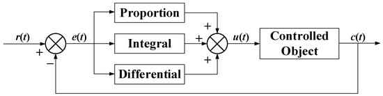
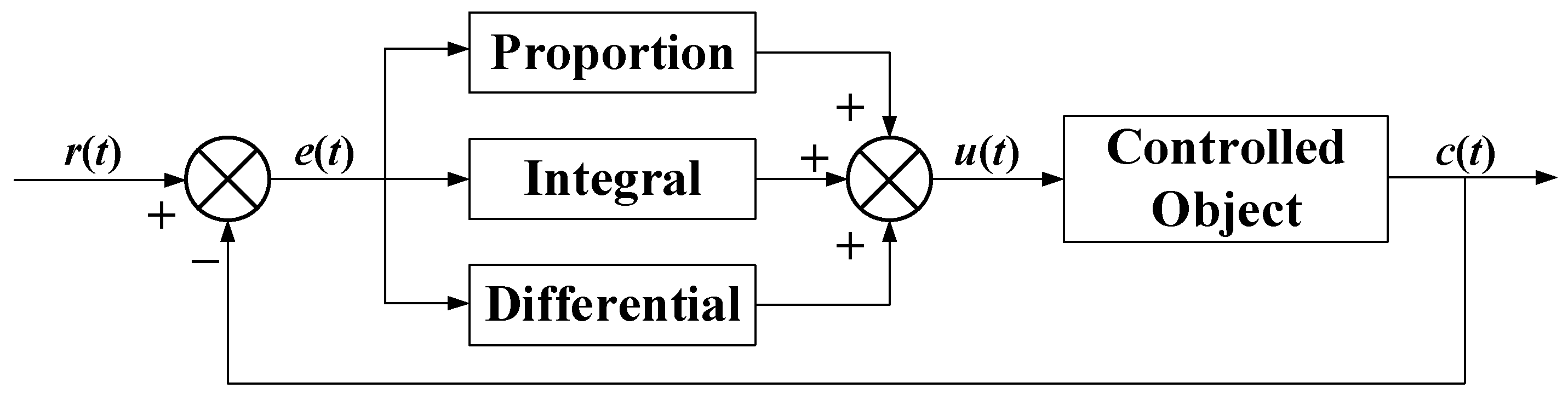
Due to the convenience of use, good robustness and high reliability of PID controllers, they are widely applied in industrial process control. The principle is to take the deviation between the input and output as the control target and reduce the deviation to the minimum by adjusting the proportional, integral and differential coefficients. In this paper, a PID controller is established, and the schematic of its control system is shown in Figure 7.
Figure 7.
The schematic of PID control system.
In the figure, r(t) is the given input values, such as the position of the towed body or the tension of the LARS; c(t) is the actual output value; u(t) is the control signal calculated by the controller; e(t) is the control deviation, where e(t) = r(t) − c(t). The PID control law is:
where KP is the proportional coefficient; KI is the integral coefficient; KD is the differential coefficient.
This study develops an external PID control module for the OrcaFlex simulation platform using the Python language. The control logic and the real-time bidirectional interaction with the dynamics simulation of the ship–cable–body coupled system are achieved through OrcFxAPI. The objective is to dynamically adjust the LARS operating speed to suppress the depth fluctuation and tension oscillation of the towed body caused by the coupling of ship heave and cable elasticity. The algorithm follows a closed-loop structure of initialization, real-time control, and state persistence.
In the initialization stage, control parameters are configured and state variables are initialized. A 10 ms sampling period is set using OrcFxAPI, and the depth or tension data is obtained at the center of mass coordinates. Custom functions are used to read the controlled object, variable type, target value, PID coefficients, start time, and speed limit from the model tags, achieving parameter decoupling. The PID parameters are determined based on the step response fitting of the OrcaFlex system model and the requirements of depth deviation < ±1 m and tension < 13.5 kN through MATLAB R2025b optimization: KP = 5.2, KI = 0.3, KD = 1.8. Meanwhile, a state class is used to store the timestamp, real-time value, integral term, and deviation change rate, and is serialized and saved in JSON format to ensure control stability and simulation continuity.
In the real-time control stage, high-frequency data acquisition, deviation calculation, and command generation are executed. After the start time is reached, the state is updated first, and then the current value is obtained through OrcFxAPI to calculate the deviation e(t). The deviation change rate is calculated using the backward difference method, and the integral term is updated using the trapezoidal method. Integral separation is enabled (the integral is paused when |e(t)| < 0.2 m) to prevent integral saturation. The speed command is generated according to the PID formula (see Equation (15)) and is limited within the allowable range to avoid actuator overload. The algorithm also outputs debugging information to support effect evaluation and parameter optimization. State persistence is achieved by saving the control state in JSON format and synchronously writing it to the simulation file by OrcaFlex. When restarting, the historical state can be restored to achieve seamless connection and meet the requirements of simulation reproducibility.
The cable is segmented according to the set length. Considering the mass and additional mass, the boundary conditions of the nodes are further dynamically adjusted based on the cable’s extension and speed, breaking through the limitations of traditional fixed boundary conditions and more accurately reflecting the dynamic coupling behavior of the ship–cable–body system.
The innovation of this study lies in the deep integration of PID control with OrcaFlex. Through OrcFxAPI, millisecond-level state feedback and command issuance are completed, breaking the limitations of offline simulation and accurately capturing the dynamic responses of multi-body systems. Combined with state saving, parameter parsing, and execution constraints in engineering design, the simulation platform acquires practical guidance capabilities, filling the gap between algorithms and engineering applications.
3. Towing System Numerical Simulation Results
Based on the above mathematical model, a 3D numerical simulation model of the towing system is constructed. For typical working conditions such as hovering, linear and turning motion, the overall model of the Ship–Cable–Body coupled system is established using the OrcaFlex to numerically simulate the dynamic response of the towed body and the cable under wave loads. It is verified that the feasibility of achieving millisecond-level real-time interaction between the state of the towed body and the retrieval and release instructions through OrcFxAPI, breaking through the limitations of traditional offline static simulation and accurately capturing the coupling effect.
3.1. Convergence Analysis of Numerical Methods
The convergence analysis of this study is based on a pure dynamic model without AHC, aiming to eliminate the interference of control algorithms and verify the stability and computational reliability of the model itself. To accurately assess the rationality of parameters such as time step and cable segment division, it is necessary to remove the influence of active control on the system response. If AHC control is enabled simultaneously, the feedback mechanism that regulates cable tension and towed body depth through the LARS will change the original dynamic characteristics of the system, making it impossible to accurately determine the numerical convergence. Therefore, the verification is conducted under the no-compensation condition, retaining only the basic external forces such as ship motion and wave loads, to make the response closer to pure dynamic behavior and ensure the objectivity and reliability of the results.
3.1.1. Time Step Convergence Verification
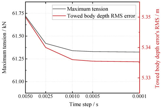
In the verification of time step convergence, the cable segment length is fixed at 2.5 m and the operation depth at 95 m. Four schemes with time steps of 0.005 s, 0.001 s, 0.0005 s, and 0.0001 s are tested, and the maximum cable tension and the root mean square (RMS) of the towed body depth error (see Equation (16)) are compared. The results show (as shown in Figure 8) that when the time step is reduced from 0.005 s to 0.0005 s, the relative change rate of the maximum tension is less than 0.63%, and the relative change rate of the depth error RMS is less than 0.27%; further reducing it to 0.0001 s, the change rates of the two indicators are reduced to within 0.01% and 0.004%, respectively. It can be seen that a time step of 0.0005 s meets the convergence requirements.
where ei represents the depth error at the i-th moment (ei = Zi − Ztarget); Zi is the actual depth of the towed body at the i-th moment; Ztarget is the set target working depth; n is the number of valid data points. The smaller the value of this indicator, the better the depth stability of the towed body.
Figure 8.
Time step convergence analysis.
3.1.2. Cable Element Length Convergence Verification
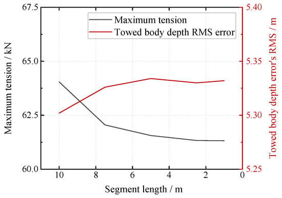
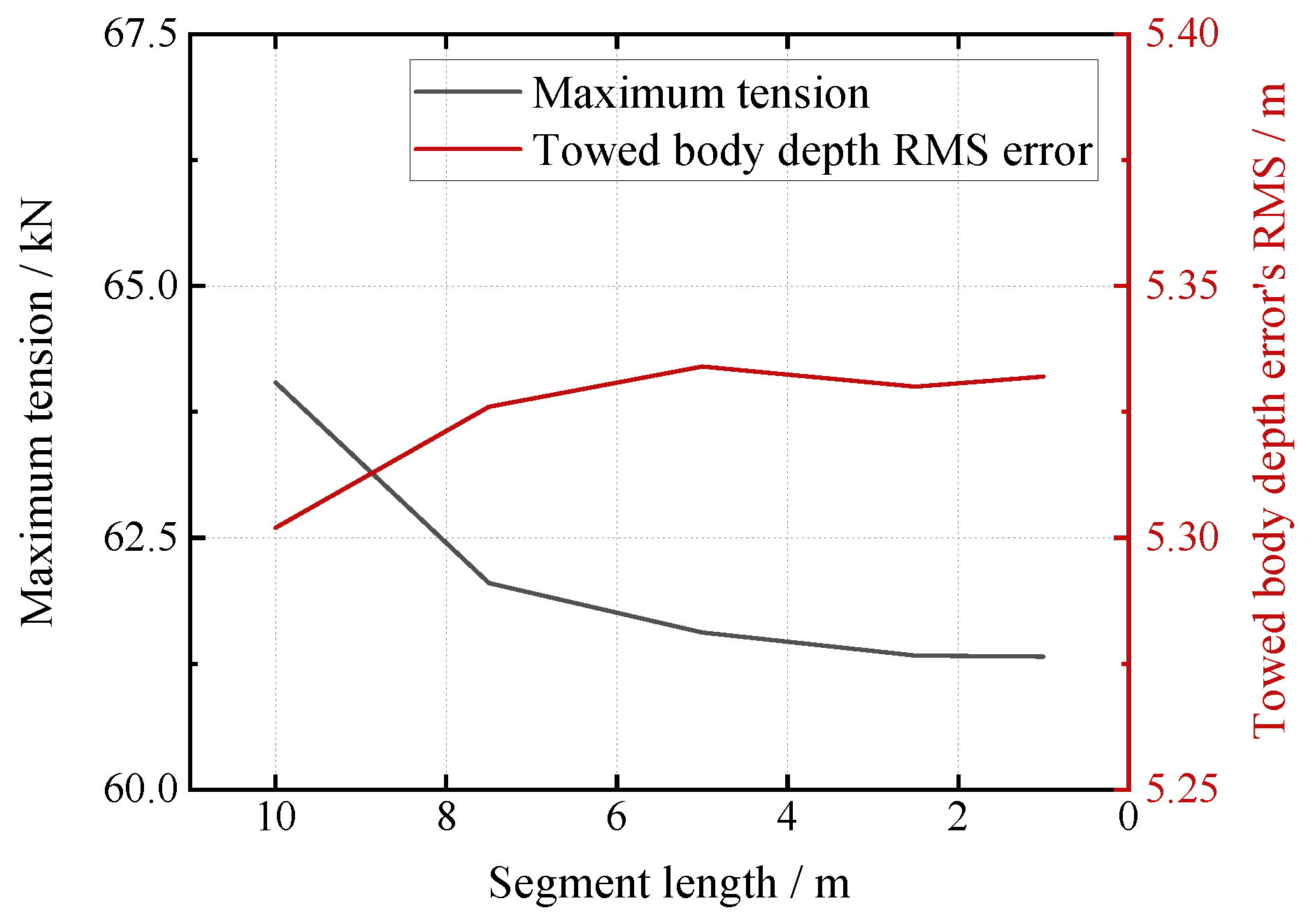
In the verification of the convergence of the cable element length, five schemes with element lengths of 10 m, 7.5 m, 5 m, 2.5 m and 1 m were tested, with a focus on observing the changing trends of the core indicators. The results show (as shown in Figure 9) that when the element length decreases from 10 m to 2.5 m, the relative change rate of the maximum cable tension is less than 4.2%, and the relative change rate of the RMS of the towed body depth error is less than 0.53%; when further reduced to 1 m, the relative change rates of the two indicators are both within 0.16% and 0.04%, respectively. Therefore, the element length of 2.5 m has met the numerical convergence requirements.
Figure 9.
Segment division convergence analysis.
The key parameters determined through convergence analysis (time step of 0.0005 s and cable element length of 2.5 m) were fixed for all subsequent simulations of both uncompensated and compensated conditions to ensure model consistency and comparability of results.
To quantitatively evaluate the control performance of the AHC system and the dynamic response of the towing system, in addition to the root mean square (RMS) of depth error, the following metrics were defined:
95th percentile depth error: The 95th percentile value of the depth error sorted in the steady-state phase, reflecting the maximum deviation in extreme cases;
Peak-to-peak (P-P) cable tension: The difference between the maximum and minimum tensions of the cable in a single simulation, used to quantify the fluctuation amplitude of the cable tension;
Compensation efficiency: Defined as , where is the peak-to-peak (P-P) tension of the cable without AHC enabled, and is the P-P tension of the cable with AHC enabled, used to quantitatively assess the tension suppression effect of the AHC system.
3.1.3. RAO Sensitivity Check
To further validate the robustness of the proposed model and AHC framework with respect to variations in RAO (the core input parameter of ship motion), a brief sensitivity analysis is conducted. RAO is selected as the key variable due to its dominant influence on towing system dynamics. Two alternative scenarios are designed: (a) RAO reduced by 20% (simulating ships with small heave response) and (b) RAO increased by 20% (simulating ships with large heave response). Using the hovering scenario as the baseline, core performance indicators are evaluated under both uncompensated and AHC-enabled conditions. The target hovering depth is set at 95 m. Results are summarized in Table 4.
Table 4.
Quantitative Evaluation Results of AHC System Control Performance.
Under uncompensated conditions, the root mean square (RMS) of depth error and the peak-to-peak (P-P) cable tension vary by less than 4% in response to ±20% changes in RAO, demonstrating that the inherent dynamic behavior of the ship–cable–body system is largely insensitive to plausible variations in RAO.
Under AHC-enabled conditions, the key performance indicators—namely depth error RMS, tension P-P, and compensation efficiency—exhibit similarly minor fluctuations within 4%. Notably, the compensation efficiency remains consistently high at 92–93% across all tested scenarios.
These results confirm the robustness of both the numerical model and the proposed AHC framework with respect to RAO variations. The selected RAO dataset, derived from built-in example ship data, is therefore justified as representative and reliable, and the overall findings are shown to be insensitive to small perturbations in RAO values.
3.1.4. Rationale for Single Waveform Design
All simulations in this study are based on a single deterministic Airy wave, without averaging over multiple wave realizations. This design is deliberately adopted to align with the core research objective: validating the dynamic coupling mechanism within the Python-PID-OrcFxAPI real-time control framework.
As a regular wave with fixed frequency and phase, the Airy wave eliminates uncertainties associated with random sea states, thereby enabling precise isolation of the interactions among ship heave motion, cable elasticity, and AHC control actions. This controlled environment ensures that the causal relationship between control inputs and system responses is clearly discernible, which is essential for verifying the effectiveness of the real-time closed-loop compensation logic.
Importantly, the reliability of the results is not undermined by the use of a single waveform. It is substantiated through multiple robustness checks: (1) numerical convergence analysis (Section 3.1.1 and Section 3.1.2) confirms the stability and consistency of the simulation model; (2) RAO sensitivity analysis (Section 3.1.3) demonstrates that the system response is insensitive to reasonable variations in ship motion input; and (3) consistently strong compensation performance, further corroborates the stability and efficacy of the proposed framework.
A potential limitation of this approach is that it does not account for the stochastic variability inherent in irregular sea conditions. However, this simplification is justified given the study’s primary focus on mechanistic validation rather than statistical performance assessment under realistic oceanic spectra. The fundamental insights into the real-time coupling control framework remain valid and generalizable, laying a solid foundation for future extensions incorporating multi-seed analyses or irregular wave models.
3.2. Dynamic Analysis of the Towing System in Hovering
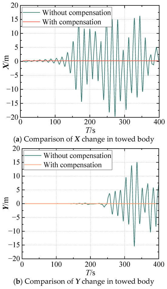
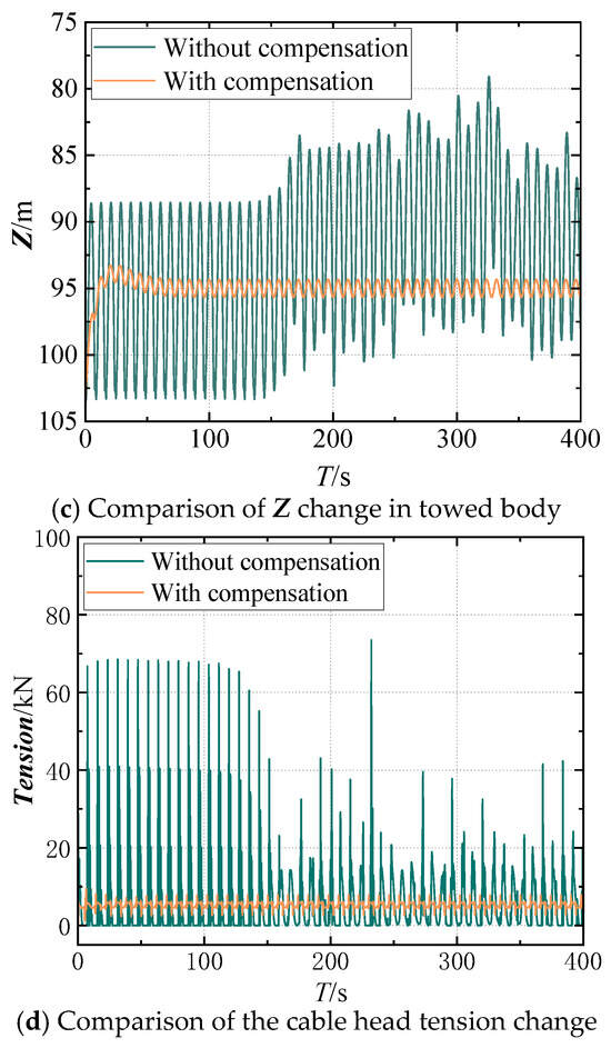
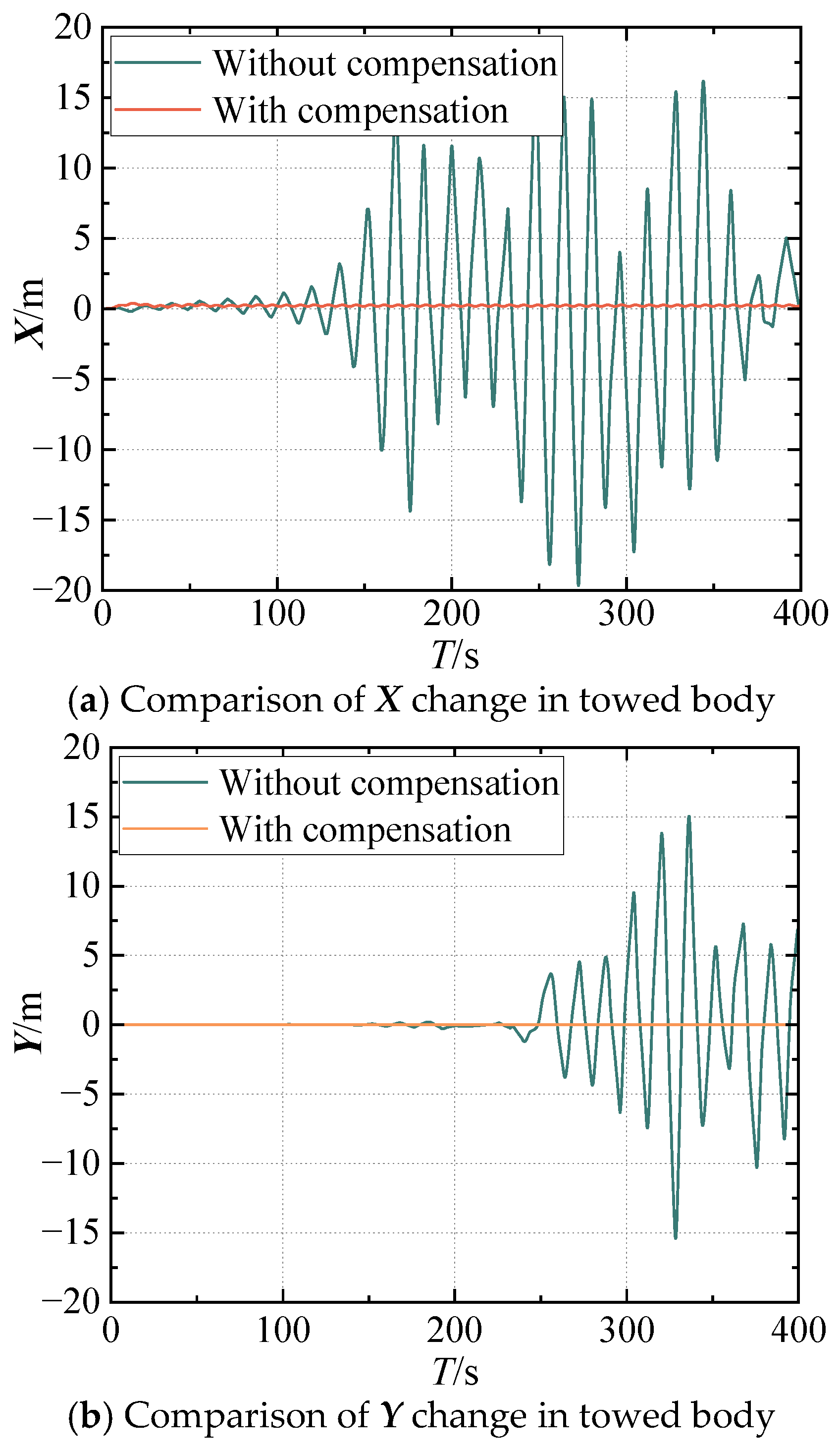
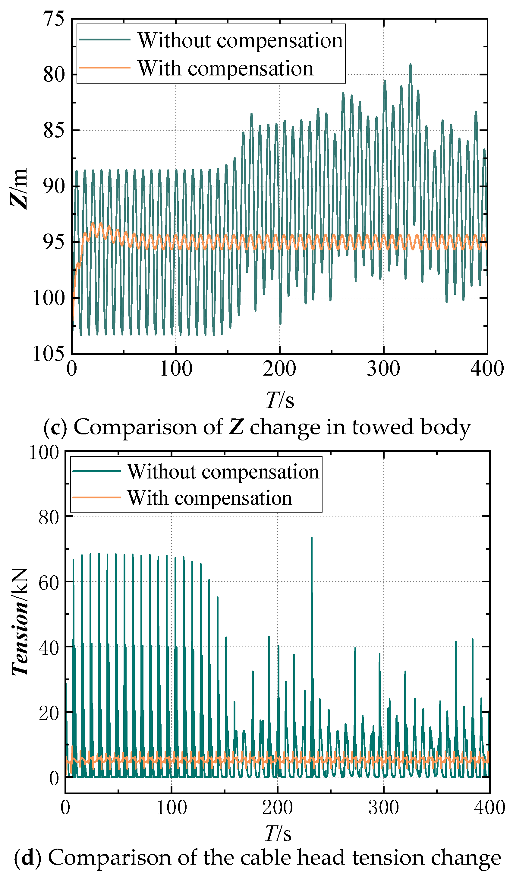
The dynamics analysis of the system in the hovering state is performed under Airy waves conditions. The preset hovering depth is set to 95 m. The heave compensation system deploys and retracts the towed cable with a motion amplitude of no more than 5 m/s. The calculation program takes the steady-state solution as the initial value and obtains the time-domain values of the towed body position and towed cable tension with and without the heave compensation system, as shown in Figure 10.
Figure 10.
Time domain value with or without heave compensation system in hover state.
As can be seen from Figure 10, the movement of the ship will drive the movement of the towed body, and the movement of the towed body has lagging and amplifying characteristics. Over time, the stability of the towed body’s motion will deteriorate increasingly. If no compensation is implemented, the towed body will eventually lose control, making it difficult to hover. The tension of the cable will also fluctuate greatly with the heave motion, which may cause damage or breakage. Hence, compensation measures must be adopted.
In contrast, the AHC system proposed in this study significantly enhances the dynamic stability and operational safety of the towed system. Under the uncompensated condition, the depth fluctuation range of the towed body is 79.11 to 103.52 m, and the tension fluctuation range of the cable reaches 0 to 73.47 kN; however, after activating the AHC, the depth of the towed body is stably controlled within 94.37 to 95.70 m (only 5.5% of the uncompensated range), and the cable tension is maintained at 2.60 to 7.81 kN (only 7.0% of the uncompensated range), completely within the SWL range.
From a quantitative evaluation perspective, the control performance of the AHC system is further verified (see Table 5). Under the uncompensated condition, the RMS of depth error is 6.47 m, and the 95th percentile depth error is 24.26 m, with the maximum cable tension and P-P tension both being 73.47 kN, reflecting severe dynamic load and positioning deviation in the system. After activating the AHC, the RMS of depth error drops to 0.80 m (a reduction of 87.6%), the 95th percentile depth error drops to 1.33 m (a reduction of 94.5%), the maximum cable tension drops to 7.82 kN, and the P-P tension drops to 5.21 kN, with a tension fluctuation compensation efficiency of 92.9%, indicating that over 90% of the dynamic tension fluctuations are effectively suppressed.
Table 5.
Quantitative Evaluation Results of AHC System Control Performance.
This indicates that the AHC system effectively mitigates the coupling effect of the ship’s vertical motion on the positioning of the towed body and the tension of the cable, achieving decoupling between the towed system and the ship’s motion through real-time adjustment of the cable’s retraction and release speed, while significantly reducing the mechanical stress load on the cable and LARS, and avoiding potential equipment damage risks.
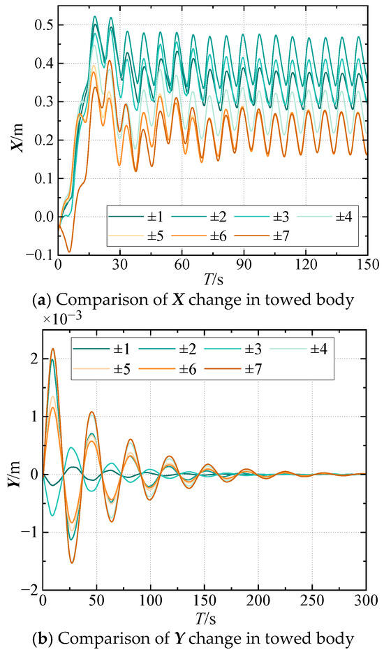
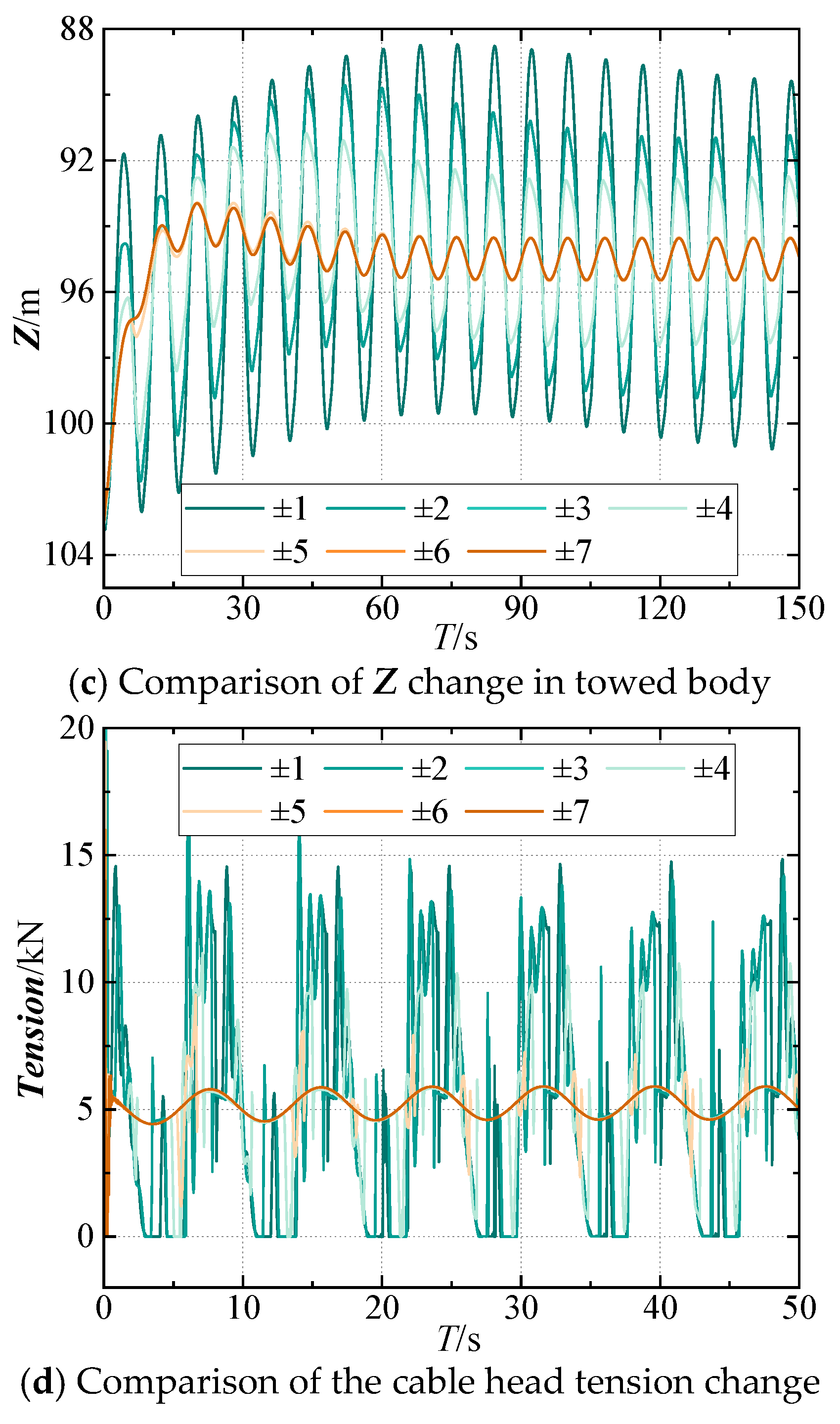
It should be noted that the cable deploying and retracting speed of the compensation system may also exert an influence on the compensation effect. For this reason, the cable deploying and retracting speed of the heave compensation system is discussed. The time-domain analysis results of the towed body motion and the tension at the head end of the cable when the amplitude is 1, 2, 3, 4, 5, 6, and 7 m/s are calculated and shown in Figure 11.
Figure 11.
Time domain values at different compensation velocities.
It is observed that as the amplitude of the cable deploying and retracting speed increases, the compensation effect improves significantly, resulting in enhanced stability of the towed body system. This improvement stems from the system’s ability to more effectively counteract vertical disturbances caused by wave-induced ship motion, thereby reducing the oscillation amplitude of the towed payload. The dynamic adjustment of cable length through controlled LARS operations enables real-time response to heave movements, which is particularly beneficial in rough sea conditions where external perturbations are more pronounced.
The quantitative analysis results show that when the amplitude of the cable’s retraction and extension speed increases from 1 m/s to 6 m/s, the system’s compensation performance continuously improves. The RMS of depth error decreases from 4.06 m to 0.77 m, the P-P tension of the cable drops from 15.08 kN to 1.31 kN, and the tension fluctuation compensation efficiency rises from 79.5% to 98.2%. This change fully confirms that an appropriate increase in the speed amplitude can significantly enhance the system’s ability to suppress vertical disturbances and is a key parameter for optimizing the compensation effect.
It is worth noting that this positive correlation does not continue indefinitely. Under the current working conditions, when the speed amplitude exceeds 6 m/s, the improvement in compensation performance enters a plateau phase, showing a clear feature of diminishing marginal returns. When the speed reaches 7 m/s, the RMS of depth error is 0.767 m (only a 0.4% decrease compared to 6 m/s), the P-P tension of the cable is 1.306 kN (only a 0.2% decrease compared to 6 m/s), and the compensation efficiency remains stable at 98.2%, without any substantial improvement.
This finding provides reliable quantitative basis for the engineering design of deep-sea towed heave compensation systems. During the system design stage, the optimal threshold for the retraction and extension speed should be determined through comprehensive modeling, simulation, and experimental verification. The design approach of unconditionally maximizing speed should be abandoned in favor of an optimized solution that balances compensation performance, energy consumption level, equipment lifespan, and sea condition adaptability, ensuring the system’s overall efficiency is optimal in actual operations.
Furthermore, this study adopts reasonable model simplification assumptions. Given that the scale and mass of the towed body and cable are much smaller than those of the towing ship, their counteractive effects on the ship’s dynamic characteristics can be disregarded. Therefore, in the simulation, it is assumed that the ship’s motion is driven solely by environmental wave forces. This simplification is in line with the engineering reality of deep-sea towing operations and does not have a substantial impact on the model’s accuracy or the validity of the research conclusions.
3.3. Dynamic Analysis of the Towing System in Linear Motion
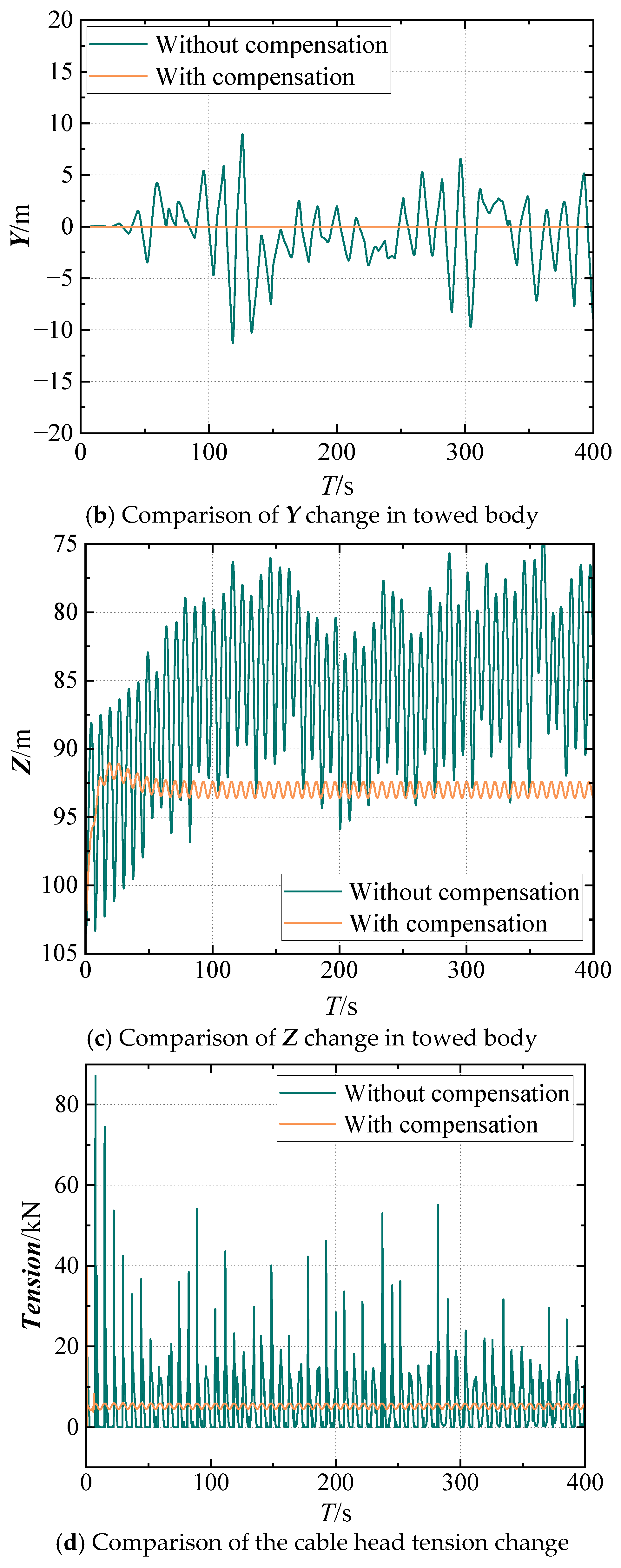
Linear motion is one of the common motions in the towing system. The dynamic analysis of the system’s linear motion state is conducted under Airy wave conditions. The ship moves at a constant velocity of 1 m/s, while the heave compensation system deploys and retracts the towed cable with an amplitude of 6 m/s. Without environmental disturbances, the towed body stabilizes at a depth of approximately 93 m, so the target depth of the heave compensation system is set to 93 m. Time-domain values of the towed body’s position and towed cable tension are computed both with and without the heave compensation system. The results of these calculations are presented in Figure 12. To ensure the statistical reliability of the results, the core quantitative indicators defined in the previous text (RMS depth error, 95% quantile depth error, peak-to-peak tension, and compensation efficiency) are adopted for performance evaluation.
Figure 12.
Time domain values with and without heave compensation system in linear towing state.
As illustrated in Figure 12, the heave compensation method used in this study effectively improves linear towing performance. Without AHC, the system shows large dynamic deviations even after reaching steady state. The towed body depth fluctuates between 74.23 and 95.88 m, far from the target depth. Cable tension varies from 0 to 55.15 kN, with frequent slack and risk of exceeding SWLs, threatening operational safety and equipment reliability. With AHC activated, system performance improves significantly. Towed body depth is stabilized between 92.39 and 93.59 m, with much smaller fluctuations. Cable tension is maintained at 4.50–5.90 kN, eliminating slack and staying within safe limits, thus preventing equipment damage.
To accurately quantify the effect, key metrics compare both conditions (as shown in Table 6). Without compensation, positioning accuracy and tension stability are poor. The RMS of depth error reaches 9.22 m, the 95th percentile depth error is 21.65 m, and the P-P tension of the cable is 55.15 kN, with significant dynamic load impact.
Table 6.
Quantitative Evaluation Results of AHC System Control Performance.
With AHC, all metrics improve sharply. The RMS of depth error drops to 1.24 m (a reduction of 86.6%), the 95th percentile depth error decreases to 1.20 m (a reduction of 94.5%). The maximum tension of the cable is 5.90 kN, the P-P tension is only 1.40 kN, and the tension fluctuation compensation efficiency is up to 97.5%.
After compensation, depth and tension fluctuation ranges are reduced to only 5.5% and 2.5% of their uncompensated levels, respectively, confirming the strong suppression capability of the system.
The results confirm that the heave compensation system effectively buffers and dynamically adjusts during linear towing. It enhances operational stability by real-time counteraction of ship heave, ensuring a consistent and predictable towed body trajectory. By strongly suppressing tension fluctuations and cable slack, it reduces mechanical stress and damage risk to the cable and LARS. This improves the safety and reliability of deep-sea towing operations. The findings provide a precise quantitative basis and technical support for designing and optimizing heave compensation systems in linear towing scenarios.
3.4. Dynamic Analysis of the Towing System in Turning Motion
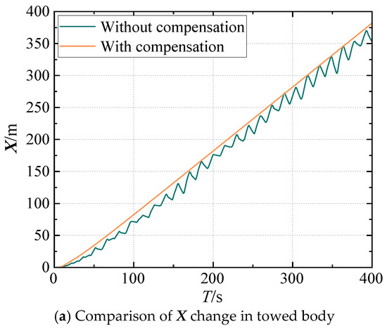
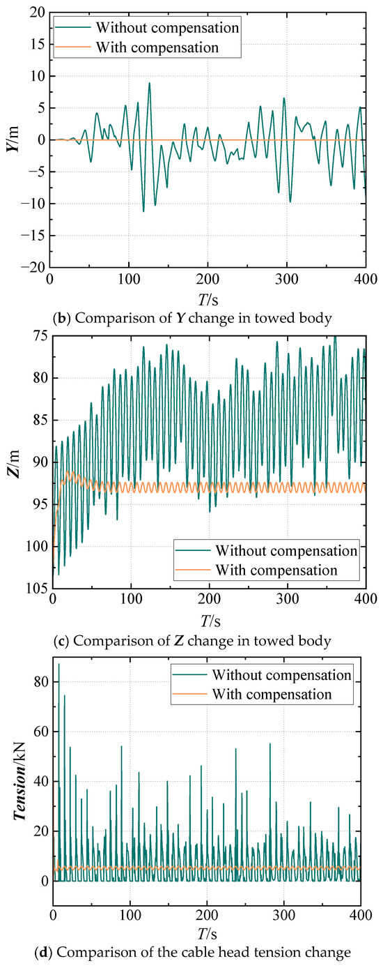
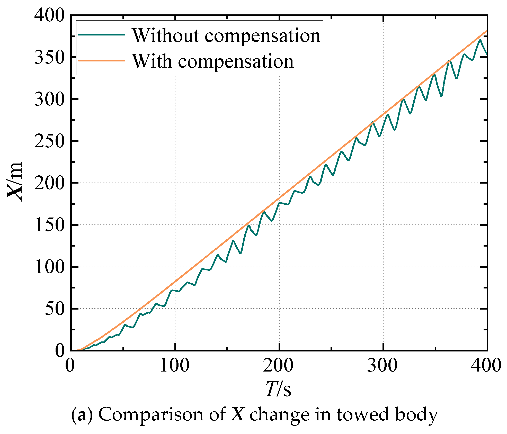
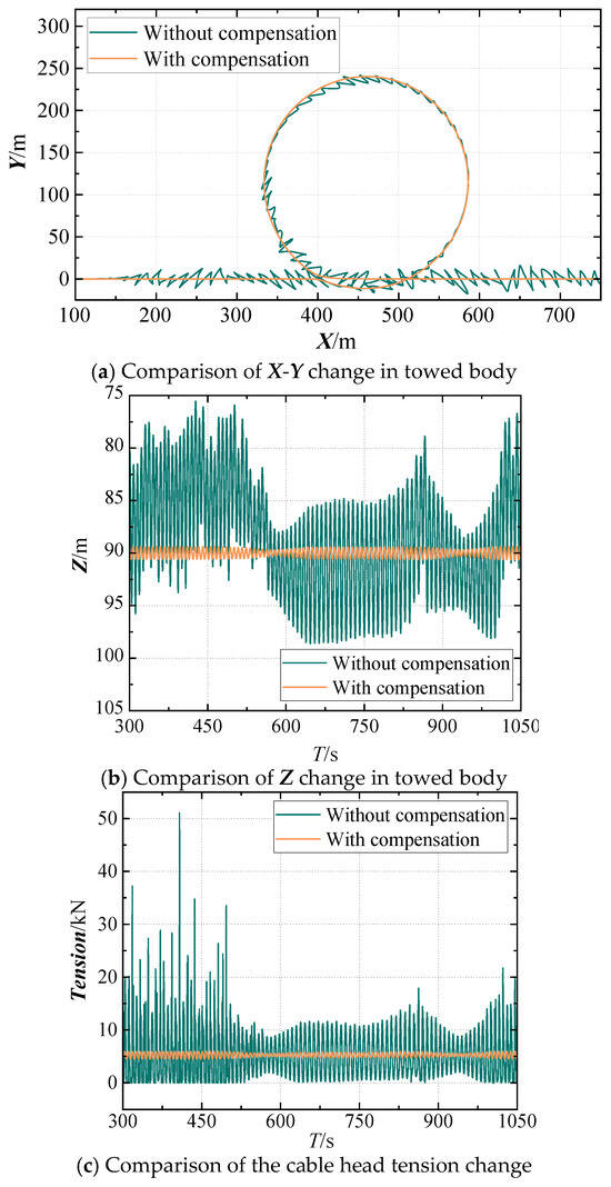
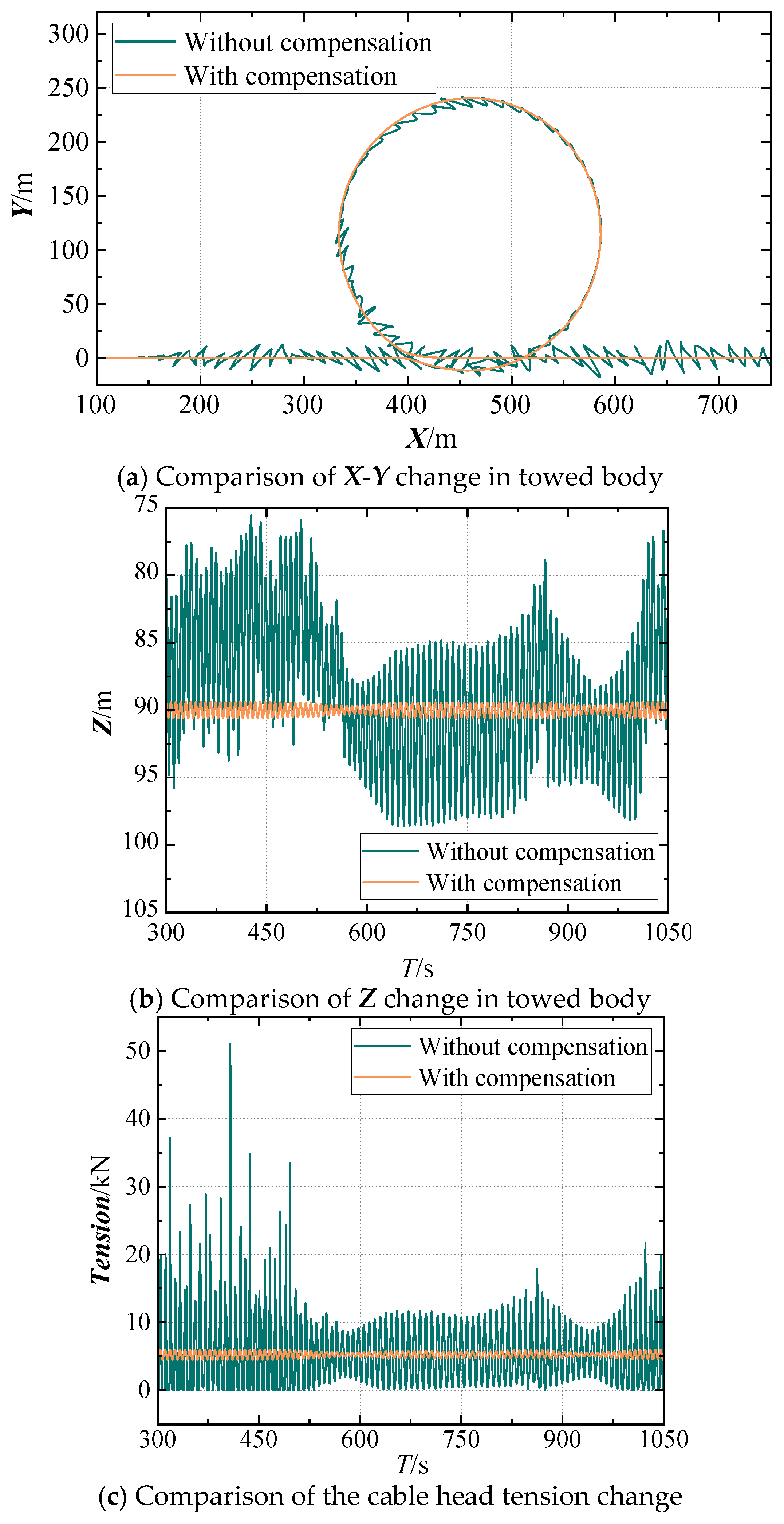
The dynamic analysis of the towing system’s turning motion is conducted under Airy wave conditions. The ship maintains a constant towing speed of 1 m/s for 400 s in a straight direction to reach a stable towing state, followed by a 360° rotation over 720 s. After completing the rotation, it resumes a stable straight motion at 1 m/s for another 400 s. The heave compensation system deploys and retracts the towed cable with an amplitude of 6 m/s. In the absence of environmental disturbances, the towed body stabilizes at a depth of approximately 90 m during turning motion; hence, the target depth for the heave compensation system is set to 90 m. Time domain values of the towed body’s position and the tension in the towed cable are computed both with and without the heave compensation system. The calculation results are presented in the following figure.
As shown in Figure 13, the vertical compensation method proposed in this study demonstrates remarkable compensation efficacy in the scenario of rotational towing motion. Without AHC, significant dynamic deviations persist even after stabilization: towed body depth fluctuates between 75.54 and 98.63 m, far from the target depth; cable head tension varies sharply between 0 and 51.05 kN, with frequent slack and potential safety risks. With AHC enabled, system performance improves significantly: depth is stabilized within 89.36–90.64 m, greatly reducing fluctuations; cable tension remains steady at 4.46–5.99 kN. Slack is effectively eliminated, and tension stays well below the SWL, ensuring operational safety.
Figure 13.
Time domain values with and without heave compensation system in gyro-towed state.
To quantify the compensation effect in rotary towing, this study compares system performance under both conditions using key metrics (as shown in Table 7). Without compensation, positioning accuracy and tension stability are poor, with a depth error RMS of 6.38 m, a 95th percentile error of 23.08 m, and a P-P cable tension of 51.05 kN, indicating high dynamic loads and significant safety risks. With AHC enabled, performance improves dramatically, about depth error RMS drops to 0.67 m (a reduction of 89.4%), and the 95th percentile error falls to 1.28 m (a reduction of 94.4%), indicating fundamental improvement in towed body positioning. Maximum cable tension is 5.99 kN, P-P tension is only 1.53 kN, and tension fluctuation compensation efficiency reaches 96.9%.
Table 7.
Quantitative Evaluation Results of AHC System Control Performance.
After compensation, the towed body depth fluctuation range is just 5.5% of the uncompensated level, and cable tension fluctuation is only 2.9%, confirming the AHC system’s strong suppression of dynamic disturbances.
The results confirm the proposed AHC method performs excellently in rotary towing. It significantly improves motion and tension stability by real-time compensation of ship heave, effectively eliminating cable slack, and achieves dual displacement and force control, aligning system response with practical engineering requirements. The simulation approach is simple and efficient, avoiding the high computational cost of complex modeling, and provides valuable guidance for deep-sea towing system dynamics and compensation design. Future work should refine the controller algorithm to enhance adaptability to complex sea states and varying conditions, further improving the system’s core effectiveness.
4. Conclusions
In harsh environments, such as those with waves, the towed cable may become overly slack or taut, resulting in continuous fluctuations in the cable tension during the towing process. This can easily lead to cable breakage and damage to the LARS. Therefore, it is necessary to apply compensation control to compensate for the movement of the umbilical cable. To solve this problem, this study proposes three core innovations to advance the latest technical level in the field of dynamics and control of deep-sea towing systems. Firstly, a real-time control-simulation framework integrating a Python-based PID controller with the OrcFxAPI enables bidirectional millisecond-level data exchange between control logic and hydrodynamic simulation, overcoming the limitations of traditional offline and static approaches. Secondly, this study expanded the application scope of AHC from traditional offshore lifting scenarios to the entire operation cycle of the towing system. Thirdly, this framework utilized a fully coupled Ship–Cable–Body dynamic model in OrcaFlex to ensure accurate capture of the nonlinear interactions between the ship’s heave motion, cable elasticity, and towed body dynamics.
The results verified the effectiveness of the proposed method. It significantly improved the stability of the towing body motion and the cable tension, completely suppressed tension relaxation, and kept the cable tension below the SWL. Both displacement compensation and force compensation demonstrated excellent performance. Additionally, a critical cable expansion speed threshold was determined, providing quantitative guidance for engineering design to avoid energy waste caused by excessive speed.
This framework has significant advantages of simple implementation and high computational efficiency, making it a practical tool for dynamic analysis of deep-sea towing systems. Future work will focus on optimizing the PID controller to further improve the compensation robustness in extreme sea conditions and expanding the model to include real-time ocean currents and wave nonlinearity to achieve wider applicability.
Author Contributions
Methodology, L.T.; Software, L.T.; Validation, L.T.; Data curation, M.J.; Conceptualization, M.J.; Writing—review & editing, C.C.; Supervision, C.C.; Project administration, C.C.; Funding acquisition, C.C. All authors have read and agreed to the published version of the manuscript.
Funding
This research was funded by the Key-Area Research and Development Program of Guangdong Province, China grant number 2020B1111010001.
Data Availability Statement
The original contributions presented in this study are included in the article. Further inquiries can be directed to the corresponding author.
Conflicts of Interest
The authors declare no conflict of interest.
References
- Driscoll, F.; Lueck, R.; Nahon, M. The motion of a deep-sea remotely operated vehicle system: Part 1: Motion observations. Ocean Eng. 2000, 27, 29–56. [Google Scholar]
- Driscoll, F.; Lueck, R.; Nahon, M. The motion of a deep-sea remotely operated vehicle system: Part 2: Analytical model. Ocean Eng. 2000, 27, 57–76. [Google Scholar] [CrossRef] [Scilit]
- Woodacre, J.K.; Bauer, R.; Irani, R.A. A review of vertical motion heave compensation systems. Ocean Eng. 2015, 104, 140–154. [Google Scholar] [CrossRef] [Scilit]
- Gu, P.; Walid, A.A.; Iskandarani, Y. Modeling, simulation and design optimization of a hoisting rig active heave compensation system. Int. J. Mach. Learn. Cybern. 2013, 4, 85–98. [Google Scholar] [CrossRef] [Scilit]
- Sun, Y.G.; Qiang, H.; Sheng, X. Genetic Algorithm-Based Parameters Optimization for the PID Controller Applied in Heave Compensation System. Appl. Mech. Mater. 2014, 556–562, 2462–2465. [Google Scholar] [CrossRef] [Scilit]
- Zhang, Q.; Tan, B.; Hu, X. Ship Heave Compensation Based on PID-DDPG Hybrid Control. In Proceedings of the 2023 42nd Chinese Control Conference (CCC), Tianjin, China, 24–26 July 2023; pp. 8576–8581. [Google Scholar]
- Huang, L.M.; Zhang, Y.T.; Zhang, L.; Liu, M.Y. Semi-active drilling draw works heave compensation system. Pet. Explor. Dev. 2013, 40, 665–670. [Google Scholar] [CrossRef] [Scilit]
- Xu, J.; Yi, B.; Zhan, Y. Review of Heave Compensation Systems: Design and Control Strategies. In Proceedings of the 2023 IEEE 11th International Conference on Computer Science and Network Technology (ICCSNT), Dalian, China, 21–22 October 2023; pp. 406–413. [Google Scholar]
- Johansen, V.; Ersdal, S.; Sorensen, J.A.; Leira, B. Modelling of inextensible cable dynamics with experiments. Int. J. Non-Linear Mech. 2006, 41, 543–555. [Google Scholar] [CrossRef] [Scilit]
- Abiow, C.M.; Schechter, S. Numerical simulation of undersea cable dynamics. Ocean Eng. 1983, 10, 443–457. [Google Scholar] [CrossRef] [Scilit]
- Htun, T.Z.; Suzuki, H.; Vallejo, D.G. On the theory and application of absolute coordinates-based multibody modelling of the rigid–flexible coupled dynamics of a deep-sea ROV-TMS (tether management system) integrated model. Ocean Eng. 2022, 258, 111748. [Google Scholar] [CrossRef] [Scilit]
- Lubis, M.B.; Kimiaei, M. Experimental Wave Flume Tests in ROV-Wave Interaction Effects on The Line Tension For A Work Class ROV in Splash Zone. In Proceedings of the ASME 2021 40th International Conference on Ocean, Offshore and Arctic Engineering, Virtual, 21–30 June 2021. [Google Scholar] [CrossRef] [Scilit]
- Zhao, C.Y.; Thies, P.; Lars, J.; Cowles, J. ROV launch and recovery from an unmanned autonomous surface vessel-Hydrodynamic modelling and system integration. Ocean Eng. 2021, 232, 109019. [Google Scholar] [CrossRef] [Scilit]
- Sarda, E.I.; Dhanak, M.R. A USV-Based Automated Launch and Recovery System for AUVs. IEEE J. Ocean. Eng. 2017, 42, 37–55. [Google Scholar] [CrossRef] [Scilit]
- Bashir, M.B.; Menon, M.; Benson, S.D.; Eastwood, R.; Murphy, A.J.; Cunny, D.; Zwanenberg, M. The Dynamic Behaviour of an ROV in Wave Affected Zones. In Proceedings of the ASME 2016 35th International Conference on Ocean, Offshore and Arctic Engineering, Busan, Republic of Korea, 19–24 June 2016. [Google Scholar] [CrossRef] [Scilit]
- Shafi, M.S.; Lu, J.H.; Song, Z.P.; Fu, Y.Q. Design and tension control of double drum winch system for deep-sea exploration equipment. In Proceedings of the 5th International Conference on Information Engineering for Mechanics and Materials, Huhhot, Mongolia, 25–26 July 2015; pp. 1474–1480. [Google Scholar]
- Huang, J.Y.; Xiao, T.B.; Chen, L. Study of control mode and control strategy for direct drive volume control actuating unit of heave compensation winch. In Proceedings of the 2017 IEEE International Conference on Cybernetics and Intelligent Systems (CIS) and IEEE Conference on Robotics, Automation and Mechtronics (RAM), Ningbo, China, 19–21 November 2017; pp. 576–580. [Google Scholar]
- Huang, L.M.; Zhang, Y.T.; Shen, R.; Wang, L.J.; Li, Y.J.; Chen, J.K. Scheme design and performance simulation of heave compensation winch for floating drilling. J. China Univ. Pet. 2021, 45, 120–126. [Google Scholar]
- Gertler, M.; Hagen, G.R. Standard Equations of Motion for Submarine Simulation; Technical Report DTMB 2510; David Taylor Research Center: Bethesda, MD, USA, 1967. [Google Scholar]
- Orcina. Documentation for Orcaflex, Version 11.0d. 2019. Available online: https://www.orcina.com/SoftwareProducts/OrcaFlex/Documentation/Help/ (accessed on 30 January 2025).
- Jiang, M.J.; Chen, C.H.; Dong, Y.K.; Zhang, L.B.; Tan, L. Research on hydrodynamic characteristics and dynamics model of an open-frame ROV moving near the wall. Ocean Eng. 2025, 320, 120358. [Google Scholar] [CrossRef] [Scilit]
- Fossen, T.I. Guidance and Control of Ocean Vehicles. Ph.D. Thesis, The University of Trondheim, Trondheim, Norway, 1999. [Google Scholar]
- Feng, Z.; Allen, R. Evaluation of the effects of the communication cable on the dynamics of an underwater flight vehicle. Ocean Eng. 2004, 31, 1019–1035. [Google Scholar] [CrossRef] [Scilit]
- Huang, S. Dynamic analysis of three-dimensional marine cables. Ocean Eng. 1994, 21, 587–605. [Google Scholar] [CrossRef] [Scilit]


Disclaimer/Publisher’s Note: The statements, opinions and data contained in all publications are solely those of the individual author(s) and contributor(s) and not of MDPI and/or the editor(s). MDPI and/or the editor(s) disclaim responsibility for any injury to people or property resulting from any ideas, methods, instructions or products referred to in the content. |
© 2025 by the authors. Licensee MDPI, Basel, Switzerland. This article is an open access article distributed under the terms and conditions of the Creative Commons Attribution (CC BY) license (https://creativecommons.org/licenses/by/4.0/).