Abstract
In response to the growing need for efficient, stable, and non-destructive gripping in apple harvesting robots, this study proposes a novel rigid–flexible coupled end-effector. The design integrates an underactuated mechanism with a real-time force feedback control system. First, compression tests on ‘Red Fuji’ apples determined the minimum damage threshold to be 24.33 N. A genetic algorithm (GA) was employed to optimize the geometric parameters of the finger mechanism for uniform force distribution. Subsequently, a rigid–flexible coupled multibody dynamics model was established to simulate the grasping of small (70 mm), medium (80 mm), and large (90 mm) apples. Additionally, a harvesting experimental platform was constructed to verify the performance. Results demonstrated that by limiting the contact force of the distal phalange region silicone (DPRS) to 24 N via active feedback, the peak contact forces on the proximal phalange region silicone (PPRS) and middle phalange region silicone (MPRS) were effectively maintained below the damage threshold across all three sizes. The maximum equivalent stress remained significantly below the fruit’s yield limit, ensuring no mechanical damage occurred, with an average enveloping time of approximately 1.30 s. The experimental data showed strong agreement with the simulation, with a mean absolute percentage error (MAPE) of 5.98% for contact force and 5.40% for enveloping time. These results confirm that the proposed end-effector successfully achieves high adaptability and reliability in non-destructive harvesting, offering a valuable reference for agricultural robotics.
1. Introduction
Apples are among the most important economic fruit crops worldwide, and China ranks among the top producers in terms of both cultivation area and yield [1]. Harvesting is a crucial stage in the apple production chain; however, the combined effects of an aging labor force and the brief harvest season have driven labor costs upward, posing a serious constraint to the sustainable development of the apple industry [2,3]. This situation underscores the urgent need for more efficient and intelligent harvesting solutions [4]. Within this context, the development of apple-harvesting robots has emerged as a leading research focus in agricultural engineering [5]. Among their components, the end-effector—the interface directly engaging with the fruit—has become a central subject of optimization efforts [6]. Current research emphasizes achieving non-destructive harvesting without compromising grasping stability, thereby enhancing both efficiency and fruit quality [7,8,9].
Apple harvesting end-effectors are generally categorized into three types according to their fruit detachment strategy: cutting type, air suction type, and finger clamping type [10,11]. Cutting type devices secure the fruit and employ rotating blades or bio-inspired enveloping mechanisms to sever the stem [12,13]. They combine high operational speed, precise positioning, and compact profiles, but are susceptible to interference from branches and foliage, require high positioning accuracy, and face adaptability limitations due to varying stem lengths. Air suction end-effectors position a negative pressure cup on the target fruit via a robotic arm; the vacuum pump generates negative pressure to attach the cup to the fruit surface, and subsequent arm movement or rotation detaches the fruit [14]. This method is simple and easy to control but is limited by bulky vacuum systems and potential damage to the fruit skin caused by suction force. Finger clamping end-effectors provide superior grip force modulation, making them particularly effective in minimizing mechanical damage, which has led to their widespread investigation and application. Structurally, these are subdivided into rigid, flexible, and rigid–flexible coupled designs [15]. Rigid grippers offer high clamping force and rapid response but rely on rigid contact, which risks damaging delicate fruit skins [16]. Flexible grippers utilize compliant finger-like structures that deform continuously upon contact, eliminating rigid joint-linkage configurations and offering high adaptability when handling fragile peeled fruits [17]. Rigid–flexible coupled grippers integrate flexible elements with a rigid frame, enhancing adaptability while further reducing harvest-related damage [18,19]. Despite these advantages, current research on such devices remains focused on structural layouts and actuation principles, with limited investigation into the underlying interaction mechanisms between flexible materials and apples during grasping. This gap has prevented their potential benefits from being fully verified.
The actuation mode of an end-effector determines its structural complexity, operational adaptability, and control methodology, and is generally classified as either fully actuated or underactuated. Fully actuated systems assign an independent actuator, such as an electric motor or pneumatic device, to each finger joint. Combined with sensors and advanced control algorithms, they can actively and precisely adapt to fruits of different sizes and geometries [20,21]. While this configuration enables smooth and stable grasping, the requirement for independent driving of each degree of freedom increases the mass, volume, and manufacturing cost of the device. In contrast, underactuated designs typically utilize a single actuator to drive multiple finger joints via mechanical linkages, achieving passive adaptation to the target object through the mechanical structure [22]. Yu et al. and Zheng et al. designed underactuated end-effectors for citrus and tomato harvesting, respectively [23,24]. However, traditional underactuated devices often lack the tactile softness required for delicate fruits. To address this limitation, the integration of “rigid–flexible coupling” with “underactuated mechanisms” has emerged as a prominent research direction in recent years. This approach aims to synergize the precise control capabilities of rigid structures with the compliant adaptability of flexible materials, and many scholars have made significant progress in this field. For instance, Kam et al. developed an underactuated rigid-soft hybrid gripper designed for free-flying manipulation, utilizing the synergy between a rigid skeleton and soft skin to adapt to non-cooperative targets [25]. Lee et al. proposed the “TWISTER Hand,” an underactuated gripper inspired by origami twisted towers, which leverages structural flexibility in coupled rigid surfaces to achieve versatile grasping [26]. Furthermore, Su et al. presented the “SAU-RFC Hand,” a novel self-adaptive robot hand with rigid-flexible coupling fingers, demonstrating superior performance in enveloping objects of various shapes [27]. However, these designs primarily rely on passive mechanical properties to protect the target object. Most end-effectors lack active perception and real-time control of contact forces during the grasping process. In agricultural harvesting, where fruit characteristics vary significantly, relying solely on passive structural adaptation cannot strictly guarantee that the gripping force remains below the biological damage threshold. Therefore, developing an end-effector that combines passive structural adaptation with active force feedback control is crucial for non-destructive robotic harvesting.
Addressing the critical challenges encountered in the development of existing harvesting end-effectors, this study presents a novel apple harvesting end-effector. The design integrates an underactuated architecture with a rigid–flexible coupled design, and incorporates a real-time force feedback system to precisely regulate contact force. It is hypothesized that combining flexible materials and underactuated finger mechanics with active force control and a twist–pull harvesting mode can achieve a balance between grasp stability and non-destructive harvesting. Accordingly, the proposed end-effector is systematically evaluated through modeling, structural optimization, simulation analysis, and experimental validation.
2. Materials and Methods
2.1. Measurement of Apple Skin Damage Force
2.1.1. Sample Preparation and Physical Parameter Measurement
In this study, “Red Fuji” apples from Xinjiang, China, were used as the test specimens. All apples were manually harvested at commercial maturity on 20 October 2024 from a dwarfing rootstock high-density orchard (80°49′0.282″ E, 41°21′22.374″ N). Immediately after harvest, the apples were placed in sealed low-permeability polyethylene bags and transferred to the laboratory within 24 h. The apples were then stored in a climate chamber (HWS-50, Shanghai Shangdao Scientific Instrument Co., Ltd., Shanghai, China) maintained at 4 °C and 90% relative humidity (RH) to inhibit physiological metabolic activities and minimize the influence of storage time on the fruit’s mechanical properties [28].
The physical parameters of apples serve as the foundation for end-effector design and simulation [29]. In this work, 100 defect-free and mechanically undamaged samples were randomly selected for measurement of equatorial diameter, fruit height, fruit mass, and fruit density. The mean values ± standard deviations obtained were 80.34 ± 4.67 mm, 67.69 ± 4.72 mm, 225.45 ± 37.41 g, and 918.58 ± 30.46 kg/m3, respectively.
2.1.2. Measurement of Surface Damage Force in Three Regions of the Fruit
To investigate the mechanical properties of apples in different regions, 50 intact apple samples were randomly selected. To minimize errors caused by sample variations, each apple was divided into six testing regions, and each testing region was further subdivided into the top, middle, and bottom. For each apple, the damage force results from the same testing region were averaged. The distribution of the testing regions is shown in Figure 1a [30,31]. The measurement of apple surface damage force was conducted at an ambient temperature of 25 °C. The testing instrument used was a TA. XT PlusC texture analyzer (SMS, Glasgow, UK; load resolution 1 g, load accuracy ± 0.01 N, displacement accuracy ≤ 0.0001 mm). A P/36R cylindrical probe was employed to perform compression tests on the apples. The compression distance was set to 4 mm to ensure plastic deformation of the fruit, and the compression speed was set to 2 mm/s [32]. The detailed test method is illustrated in Figure 1b.
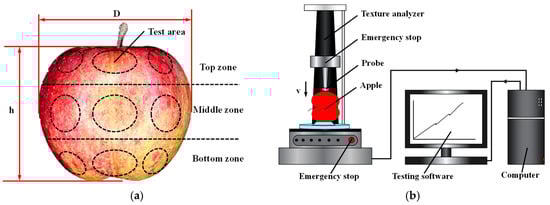
Figure 1.
Regional distribution of apples and experimental methods. (a) Distribution of apple testing regions and geometric parameters; (b) Compression test method.
Figure 2a shows a representative load–displacement curve obtained during compression. In the initial stage, the apple specimen undergoes elastic deformation without permanent mechanical damage. The damage point 1 indicates the onset of irreversible deformation (plastic damage) and was defined as the damage threshold used for statistical analysis. With continued loading in the same compression step, further damage accumulation may occur, leading to a damage point 2, which reflects subsequent damage progression and was not used for threshold statistics. Statistical analysis of all damage thresholds showed that the minimum damage forces for the top, middle, and bottom regions were 24.33 N, 26.38 N, and 26.37 N, respectively. The statistical results of damage force thresholds are presented in Figure 2b.
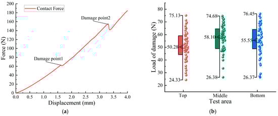
Figure 2.
Results of apple damage testing. (a) Load–displacement curve during apple compression; (b) Box plot shows the distribution of damage load (N) for apples tested at the top, middle, and bottom regions. The box represents the 25th–75th percentiles, and the line inside the box indicates the median value. All data were analyzed using the Grubbs test (α = 0.05), and no significant outliers were detected.
2.2. Design of the End-Effector
When designing the end-effector, the goal should be to ensure reliability and adaptability while minimizing any damage to the apples. Efficient and non-destructive harvesting by the end-effector has become a key research focus for many experts and scholars. The core of non-destructive harvesting lies in reducing the contact force between the end-effector and the apple during the gripping process. However, for a finger-clamp-type end-effector, reducing the contact force may lead to slippage during harvesting operations, or result in the inability to rotate or twist the apple to reduce the detachment force and preserve the fruit stem [4]. To address this issue, we propose the following structural design scheme for the end-effector.
2.2.1. Structure Design of End-Effector
Underactuated structures are generally defined as mechanical systems in which one or more joints operate without direct actuation. Unlike fully actuated end-effectors, the number of actuators in an underactuated end-effector does not have to correspond exactly to the system’s mechanical degrees of freedom. Due to having more degrees of freedom than actuators, underactuated systems require constraints provided by the grasped object, elastic components (e.g., torsion springs), and specific mechanical arrangements. These passive adaptation mechanisms enable the end-effector’s fingers to autonomously adjust their posture during grasping, conforming to the geometric features of the target object to accomplish a secure grasp.
Based on the principle of underactuation, this study designed and fabricated a three-finger, rigid–flexible coupled end-effector specialized for apple harvesting. The device comprises three primary subsystems: the enveloping mechanism, the driving mechanism, and the fixing mechanism. The enveloping mechanism consists of the proximal phalangeal region (PPR), middle phalangeal region (MPR), distal phalangeal region (DPR), and their corresponding silicone coverings—proximal phalangeal region silicone (PPRS), middle phalangeal region silicone (MPRS), and distal phalangeal region silicone (DPRS)—each mounted on the rigid phalangeal segments. This configuration enables the end-effector to fully envelop the fruit during harvesting. The driving mechanism incorporates a direct current (DC) motor, a transmission worm, and a customized worm gear. It transfers torque to the fingers, and owing to the self-locking nature of the worm gear–worm assembly, finger positions remain fixed when the motor is deactivated, preventing accidental fruit release due to incomplete closure. The fixing mechanism includes a suction cup and a finger base. The suction cup minimizes collision between the apple and rigid structural components caused by positioning inaccuracies or environmental factors, while the finger base stabilizes the position of the remaining structural elements. Torsion springs are integrated into the distal interphalangeal joint (DIP), proximal interphalangeal joint (PIP), and metacarpophalangeal joint (MCP), ensuring the fingers remain unbent until in contact with the target fruit. Once the driving torque surpasses the constraint force provided by the torsion springs, the fingers conform to the fruit’s contour, achieving a secure enveloping grasp. The end-effector’s structural configuration is illustrated in Figure 3.
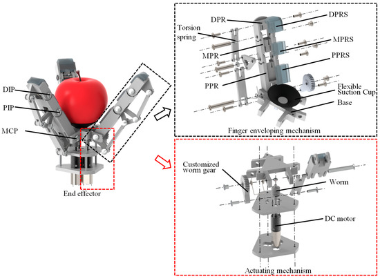
Figure 3.
Structure sketch of end-effector.
During the grasping process, the motor initiates rotation of the worm, which transmits torque to the customized worm gear. Through the connecting rod, this motion drives the entire finger to rotate about its base. In this motion, the torsion spring and the mechanical assembly jointly function as limiting mechanisms, effectively minimizing unintended movements of the MPRS and DPRS caused by gravity or inertia. Consequently, the finger achieves a stable and precisely controlled grasp.
2.2.2. Static Analysis of the Finger Structure
During the grasping operation of the end-effector, the PPR, MPR, and DPR sequentially contact the apple and become constrained, thereby determining the overall finger configuration. By performing static analysis of the finger, the contact forces , , and generated between a single finger and the apple can be calculated. The geometric and static force models of a single finger are shown in Figure 4a.
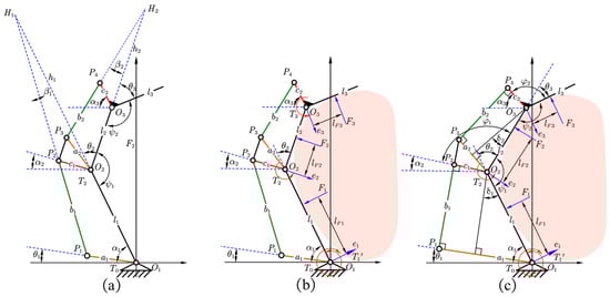
Figure 4.
Single-finger mechanical analysis models. (a) Finger geometric model; (b) Finger static analysis model; (c) Finger ideal-state grasping model.
In the static analysis of the three joints, the weight of the finger and the friction between the finger and the object are neglected. Based on the principle of virtual work, the following can be derived:
where is the driving torque of the underactuated finger; represents the virtual angular velocity vector at each joint of the finger mechanism; denotes the reaction force exerted by the apple on the flexible silicone of the end-effector; and is the velocity vector at the point of application of the external force along the direction of that force, where
The driving torque can be expressed as:
where is the input torque of the motor, and is the torque of the torsion spring at the MCP joint.
Expanding Equation (1) gives:
There exists a Jacobian matrix such that the linear velocity vector and the angular velocity vector satisfy:
The transformation matrix of is:
From Equations (1)–(6), we can derive:
By deriving and , the contact force can be obtained. The derivation process of and is given in detail in Reference [33]. That is,
The calculation method of is as follows:
Since the three joints are interconnected through two four-bar linkage mechanisms, the linear velocity vector is:
As shown in Figure 4b, based on the three-center theorem, an analysis of quadrilateral and quadrilateral yields the relationship between and the angular velocity, as follows:
where denotes the length of line segment , and denotes the length of line segment ; both lengths can be determined from the geometric configuration of the finger.
By substituting Equations (8) and (11) into Equation (7), the contact force is obtained as:
where denote the effective moment arms of in the clockwise direction, as shown in Figure 4b. The coefficients and are defined as:
2.3. Structural Optimization Based on Genetic Algorithm
To ensure that the end-effector can adapt to apples of different sizes and shapes, parameter optimization of its key structural elements was carried out. Based on measurements of the basic geometric parameters of apples, and considering the structural dimensions of human fingers, the lengths of PPR, MPR, and DPR were set to , , and , respectively. According to the fundamental principles of mechanism kinematics, the efficiency of force transmission reaches its maximum when the transmission pressure angle is zero—specifically, is perpendicular to , is perpendicular to , is perpendicular to , and is perpendicular to , with . For simplification, the ideal grasping posture of the finger mechanism was chosen as the optimization baseline, as shown in Figure 4c. In this configuration, the MCP joint rotates approximately , the PIP joint approximately , and the DIP joint approximately . This posture served as the optimization baseline. Since achieving uniform contact force distribution is critical for preventing local stress concentration and reducing peel damage [34], the objective function was formulated to minimize load disparity among the PPRS, MPRS, and DPRS. It is worth noting that this function targets relative uniformity, excluding friction factors and absolute force constraints. Accordingly, the objective function is defined as:
under this assumption:
The following geometric constraints are imposed:
where is the stiffness coefficient of the torsion spring, and is the initial torque of the torsion spring.
The finger structural parameters , , , , and were taken as optimization variables, and frictional forces between finger components as well as those between the torsion spring and the finger components were disregarded. The optimization ranges for , , , , and were defined by combining the structural characteristics of the human hand with the geometric features of the apple determined in Section 2.1.2, with lower bounds and upper bounds . The optimization was carried out in MATLAB R2018a (MathWorks, Natick, MA, USA) using the genetic algorithm (ga) from the Global Optimization Toolbox (Version R2018a), with a population size of and a stall generation of , while other parameters were kept at default values [35].
This relatively large population size was selected to improve global search capability and reduce the risk of premature convergence, given the complexity of the coupled mechanism geometry and spring parameters. The program was terminated when the weighted average change in the fitness function was less than , a threshold chosen to ensure the algorithm achieved a stable and high-precision convergence. Multiple independent runs produced ten sets of data, as shown in Table 1, and the dataset from the sixth run, which had the smallest objective function value , was selected as the design parameters. The optimized results were rounded to integers, yielding , , , , a torsion spring stiffness of , and an initial torsion spring torque .

Table 1.
Optimization results of finger structural parameters.
2.4. Rigid–Flexible Coupled Dynamic Simulation Model of the End-Effector
As previously mentioned, the end-effector tends to cause damage to apples during the grasping process; therefore, it is necessary to analyze the interaction between the flexible silicone layer covering the finger surface of the end-effector and the apple in order to achieve non-destructive harvesting. This process can be simulated via rigid–flexible coupling analysis using Adams (2020, MSC Software Corporation, Newport Beach, CA, USA). However, due to the limitations of Adams in flexible body modeling, in this study, the flexible components were generated in Ansys (2024 R2, Ansys Inc., Canonsburg, PA, USA) and then imported into Adams (2020, MSC Software Corporation, Newport Beach, CA, USA) to create the flexible parts.
2.4.1. Generation Method for the Flexible Body
(1) Geometric model construction. To obtain a more realistic three-dimensional model of the apple and improve the solution accuracy of the subsequent rigid–flexible coupled finite element model, three types of apple geometric models with different sizes were established. As shown in Figure 5a, the apple samples were evenly sliced along the axis, and cross-section photographs were taken to capture the outer contour images of the apples. The contours were scanned using GetData Graph Digitizer (v2.26, GetData Pty Ltd., Sydney, Australia) to obtain the outer contour coordinates of the apple cross-sections, yielding 498 contour points. These contour points were imported into SolidWorks (2024, Dassault Systèmes S.A., Waltham, MA, USA), and the curve formed by these points was rotated 360° about the Y-axis to generate the solid apple model, as shown in Figure 5b. The flexible silicone was modeled based on the rigid phalangeal structure, and likewise drawn using SolidWorks.
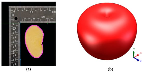
Figure 5.
Three-dimensional modeling of the apple. (a) Extraction of apple contour points. (b) Three-dimensional model of the apple.
(2) Selection of finite element types. In constructing the finite element model, the SOLID187 element (10-node tetrahedral) was selected to represent the apple model in Ansys. This element is capable of accurately modeling irregular meshes and curved surfaces, thereby minimizing the geometric discretization errors inherent in the biological apple model. The flexible silicone component was modeled using the SOLID185 element (8-node hexahedral). This element exhibits superior performance in handling the large deformation and incompressibility of elastic materials, and it provides stable convergence in complex contact analyses.
(3) Mesh Generation and Quality Control. To balance computational efficiency and analytical accuracy, a mesh sensitivity analysis was conducted. We evaluated the simulation results for the apple model at element sizes of 1 mm, 4 mm, and 8 mm, and for the flexible silicone model at 0.5 mm, 1 mm, and 2 mm, using contact force and equivalent stress as convergence indicators. The results indicated that when the element sizes were set to 4 mm for the apple and 1 mm for the flexible silicone, the optimal balance between efficiency and accuracy was achieved (relative error < 5%). Therefore, the element size was set to 4 mm for the apple solid and 1 mm for the flexible silicone. The apple solid model was meshed into 7971 SOLID187 elements (70 mm), 9452 SOLID187 elements (80 mm), and 11,924 SOLID187 elements (90 mm), respectively. The flexible silicone was meshed into 9072 SOLID185 elements (PPRS), 6048 SOLID185 elements (MPRS), and 7756 SOLID185 elements (DPRS). The mesh division result is shown in Figure 6. A mesh quality check showed that the orthogonal quality of both the apple and the flexible silicone exceeded 0.9, meeting the simulation requirements.
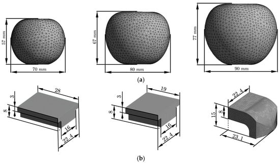
Figure 6.
Mesh division of the apple and silicone. (a) Dimensions and mesh division of the apple: from left to right are apples with diameters of 70 mm, 80 mm, and 90 mm; (b) Dimensions (mm) and mesh division of the flexible silicone: from left to right are PPRS, MPRS, and DPRS.
2.4.2. Establishment of the Rigid–Flexible Coupled Simulation Model
After exporting the flexible body Modal Neutral File (MNF) file, the three-dimensional model in Parasolid format (.x_t) was imported into the Adams/View multibody dynamics environment. Using the Flex module, the rigid solids of the apple and each flexible silicone component were replaced with their corresponding flexible MNF files. All fixed screws, nuts, and torsional springs were removed, and replaced with revolute joints and torsional spring dampers, respectively. Fixed joints were used to couple the CM Marker of each silicone flexible body with the corresponding rigid domain of the phalange. Accordingly, the silicone–phalange interface (between the bottom surface of the flexible silicone components PPRS, MPRS and DPRS and the rigid phalanx surface) was modeled as perfectly fixed, without interfacial slip or separation. The finger base was fixed to the ground, and a contact pair based on the IMPACT function was defined between the silicone finger surface and the apple skin. A rigid–flexible coupling dynamic simulation model was thus established, as shown in Figure 7. The materials and simulation parameters used in the model are summarized in Table 2.
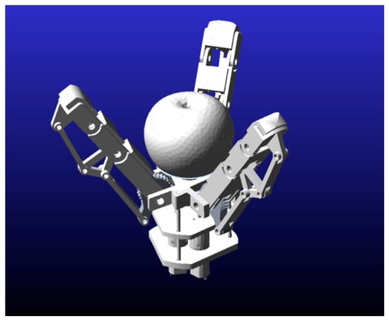
Figure 7.
Dynamic model of rigid-flexible coupling simulation.
Table 2.
Materials and model parameters used in the simulation.
2.5. Experimental Platform
To verify the gripping stability and non-destructive harvesting performance of the proposed underactuated rigid–flexible coupling end-effector for apple picking, an experimental harvesting platform was constructed as shown in Figure 8. The platform consists of the end-effector, a REALMAN robotic arm (model RML63-B, Realman Intelligent Technology Co., Ltd., Beijing, China), and a mobile chassis, simulating the orchard harvesting environment.
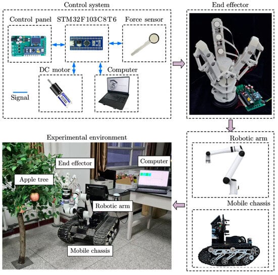
Figure 8.
Construction of the experimental platform.
The body of the end-effector is made of polished nylon material and manufactured via 3D printing, offering advantages such as light weight and high strength. The soft silicone parts (PPRS, MPRS, and DPRS) are molded using an room temperature vulcanizing (RTV2) liquid platinum-cured silicone rubber (MCPLA-L05A/B, MC Silicone, Dongguan, China) and cured at room temperature for 4–6 h. This material features low viscosity, high fluidity, and fast curing, and has a Shore A hardness of 5 after curing. Its tensile strength is approximately 36.7 kg/cm2 and its tear strength is approximately 16.3 kg/cm, while also exhibiting excellent heat resistance and wear resistance, which fully meets the requirements of the end-effector. The silicone contact pads are bonded to the rigid nylon phalanges using a fast-drying, primerless silicone adhesive (KD-866, JINGSHUN, Dongguan, China). Before bonding, the nylon surface is cleaned to remove dust and oil contamination to ensure a fully fixed attachment.
To achieve stable and adjustable contact force control and reduce the risk of fruit damage, a control system with real-time detection and control capability was developed. The system primarily consists of a microcontroller (STM32F103C8T6), a GA16Y direct-current motor(Shenzhen Xinyongtai Motor Co., Ltd., Shenzhen, China), a motor driver chip (A4950, MSKSEMI, Taiwan, China), a thin-film pressure sensor (RX-D1915, RUNESKEE, Shenzhen, China; range: 0.2–10 kg, thickness: 0.2 mm), and limit switches. The pressure sensor is directly installed at the contact surface between the flexible silicone and the apple, enabling real-time monitoring of contact force throughout the clamping process.
After the system is powered on, the microcontroller automatically performs link detection and zero-point calibration for all pressure sensors. The voltage division corresponding to each sensor’s resistance at startup is defined as the reference zero value, eliminating initial deviations caused by installation errors or residual surface contaminants, thereby improving the stability and accuracy of subsequent sampling. The microcontroller then sends pulse width modulation (PWM) pulses to control the A4950 driver chip, which integrates an H-bridge circuit capable of forward/reverse rotation and speed regulation of the DC motor.
The control process is illustrated in Figure 9. Prior to the experiment, standard weights were used to calibrate the pressure sensors to establish the relationship between output voltage and contact force. In the experiment, motor operating parameters and contact force thresholds were set via push-button input, and the motor drove the finger mechanism to perform enveloping motions according to the preset mode. During this process, the microcontroller continuously acquired signals from the pressure sensors and transmitted them in real time to the host computer via a USART serial port (baud rate: 115,200). The sensor output signals were sampled using an analog-to-digital converter (ADC) at a frequency of 50 Hz and converted into actual voltage division values. Throughout the entire experiment, all sampled signals were processed using mean filtering to remove signal noise, automatically normalized, zero-point corrected, and uploaded in real time, effectively reducing short-term and long-term drift of the pressure sensors caused by installation or environmental interference factors.
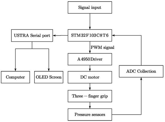
Figure 9.
Schematic diagram of the control system.
2.6. Low-Damage Apple Harvesting Technique and Mechanical Damage Assessment
We propose a low-damage apple harvesting strategy specifically designed for this end-effector. The end-effector approaches the target apple along the axis connecting the fruit stem and calyx. When the calyx is close to the flexible suction cup, the fingers perform an enveloping motion. Once a stable grasp is achieved, the robotic arm rotates the end-effector joint to separate the stem from the branch. Subsequently, the robotic arm moves the end-effector away from the tree, completing the low-damage apple harvesting process [37,38].
To verify the gripping performance of the proposed rigid–flexible coupled end-effector during apple harvesting, this study selects contact force and contact stress as the key evaluation parameters. The former is used to analyze the mechanical interaction between the end-effector and the apple surface, while the latter is employed to determine whether mechanical damage occurs to the fruit during grasping.
2.6.1. Contact Force Constraints
During the harvesting process, the mechanical interaction between the end-effector and the apple primarily consists of two components: the normal contact force and the tangential friction force . The normal contact force is defined as the force exerted by the end-effector on the apple surface in the normal direction within the contact area, and it is one of the main factors causing local bruising on the apple surface. The tangential friction force is defined as the friction force in the tangential direction within the contact area. During the rotational separation stage, it plays the role of transmitting the torsional load output from the robotic arm to the pedicel–branch interface. In the contact area, the normal contact force and tangential friction force follow the Coulomb friction relationship:
where is the static friction coefficient between the flexible silicone and the apple surface.
During the gripping process, the load exerted by the end-effector on the apple must remain below the apple’s damage threshold. According to the static compression test results in Section 2.1.2, the minimum damage force for ‘Red Fuji’ apples is 24.33 N. That is, when the local normal load exceeds this value, irreversible mechanical damage occurs to the fruit. Therefore, during the gripping stage, the contact force between the end-effector and the apple should satisfy:
In the rotational detachment stage, while maintaining a stable grasp, the torsional load must be transmitted through the tangential friction between the three fingers and the apple surface. In the design of the end-effector, the normal contact force between the apple and the fingers should be kept as small as possible to minimize damage during grasping; however, if the friction provided by the three fingers is insufficient, the apple may slip during rotation, resulting in detachment failure. According to previous research, the average torque required to fracture the stem–branch connection interface during rotational detachment is [39]. Therefore, the minimum normal contact force for a single finger, , must satisfy:
where is the minimum normal contact force between the end-effector and the apple, is the apple radius, and is the number of fingers.
From the above analysis, the normal contact force should comply with the following constraint:
To analyze the grasping requirements for apples of different sizes, taking , , and , the calculated minimum normal contact force per finger is only about 0.87 N. Therefore, in the simulations and control system of this study, the contact force threshold between the distal silicone pad of the fingers and the apple was set to 24.00 N to achieve a balance between “reducing contact force to prevent damage” and “maintaining sufficient contact force to ensure successful detachment.”
2.6.2. Stress-Based Injury Assessment
Contact stress is a key parameter for evaluating the localized concentration of forces on the apple peel and internal flesh during the gripping process, and is regarded as the most scientific indicator for determining whether the end-effector causes bruising during grasping [40]. Contact stress depends not only on the applied force, but also on the material properties and geometric shape. In this study, both the flexible silicone and the apple are defined as flexible materials, and their contact radius can be expressed as:
where is the effective contact radius, and is the radius of the contact region on the apple.
It should be noted that the validity of Equation (21) is predicated on the assumption that the silicone surface is planar or possesses a radius of curvature significantly larger than that of the apple. Given that the flexible silicone in this study utilizes a planar contact surface, this geometric prerequisite is satisfied. Therefore, the effective elastic modulus can be expressed as:
Furthermore, although apple tissue is a non-homogeneous material, which limits the applicability of the standard Hertz model, the fruit is treated here as an equivalent homogeneous medium. This serves as a necessary engineering approximation to derive the peak contact stress. Based on this, the expression is given as:
where denotes the radius of the contact region; represents the contact stress at the center of the contact region; and is the contact force exerted within the contact region.
Although the design and control in this study focus on limiting the contact force between the flexible silicone and the apple, the fixed contact geometry of the end-effector means that and the maximum contact stress on the fruit surface are proportionally related, consistent with the derivation above. Therefore, in the control strategy, reducing the gripping force will inevitably and simultaneously reduce the contact stress applied to the fruit surface, thereby achieving the dual objective of preventing both force-induced damage and stress-induced damage.
3. Results and Discussion
3.1. Simulation Results
3.1.1. Dynamic Analysis of End-Effector Grasping
To assess the end-effector’s adaptability to apples of varying sizes, kinematic simulations of finger motion were performed for apples with equatorial diameters of 70 mm, 80 mm, and 90 mm. Drawing on the results of the previous determination of apple damage (with a minimum damage force of 24.33 N at the top), the simulation was configured to cease actuation once the contact force between the distal phalangeal region silicone (DPRS) and the apple reached 24 N.
The finger motion postures for grasping apples of different sizes are illustrated in Figure 10. Simulation results show that, regardless of apple size, the grasping process follows the same sequence: the proximal phalangeal region silicone (PPRS) contacts the apple first, followed by the middle phalangeal region silicone (MPRS), and finally the distal phalangeal region silicone (DPRS) completes the enveloping action. This consistent sequence demonstrates that the finger mechanism maintains high stability when handling objects of varying sizes. While the grasping sequence is uniform, the enveloping time varies significantly among sizes. Grasping a small apple requires 1.49 s, a medium apple 1.32 s, and a large apple only 1.12 s. The difference is primarily attributed to the effect of fruit diameter on the finger closing path length: smaller fruit necessitates a greater finger rotation angle to form an envelope, thereby increasing the closure time.
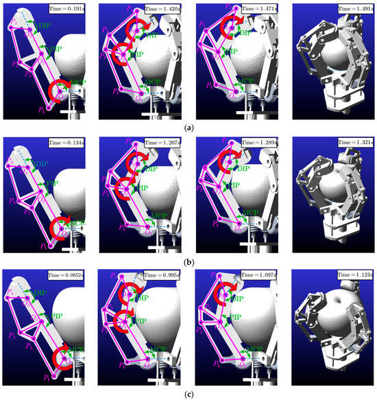
Figure 10.
Dynamic grasping process of the end-effector. (a) Grasping a 70 mm apple; (b) Grasping an 80 mm apple; (c) Grasping a 90 mm apple.
Figure 11a–c shows the time-varying curves of the rotation angles of the metacarpophalangeal (MCP) joint, the proximal interphalangeal (PIP) joint, and the distal interphalangeal (DIP) joint during the grasping of apples in three different sizes. In conjunction with Figure 10, it can be observed that, when grasping apples of varying sizes, the MCP joint first rotates until the PPRS contacts the apple surface. During this phase, due to the constraint of the torsion springs on the PIP and DIP joints, the finger rotates clockwise about point O1 in space. At the moment of contact between the PPRS and the apple, the MCP joint ceases rotation due to the combined constraints of the apple and the torsion springs. Similarly, when the MPRS contacts the apple, the PIP joint stops rotating, and the angular velocity of the DIP joint increases until the DPRS contacts the apple, thereby completing the enveloping motion.
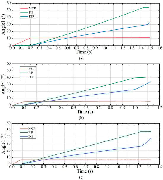
Figure 11.
(a–c) show the rotation angles of each joint when grasping apples with equatorial diameters of 70 mm, 80 mm, and 90 mm, respectively.
Notably, once the MCP joint ceases rotation, the PIP and DIP joints commence flexion simultaneously; nevertheless, the slope of their respective curves reveals that the PIP joint maintains a consistently higher angular velocity than the DIP joint. This behavior arises from the non-uniform transmission characteristics inherent in the four-bar linkage mechanism. After the MCP joint stops, the a1 link continues its clockwise rotation about point O1, transmitting force first through the first-stage four-bar linkage O1P1P2O2 to the middle phalanx, and subsequently through the second-stage four-bar linkage O2P3P4O3 to the distal phalanx. In this phase, the second-stage linkage operates with a relatively low instantaneous transmission ratio, thereby producing a smaller angular velocity output to the DIP joint. This non-uniform transmission shortens the enveloping duration and enhances grasping stability. Simulation results further confirm that, when grasping apples of three different sizes, the end-effector achieves similar finger kinematic postures, demonstrating the structure’s strong adaptability to varying apple dimensions.
3.1.2. Analysis of Contact Forces During Grasping
Figure 12a–c shows the dynamic curves of contact force over time between different phalangeal region silicones and the apples during the grasping of small (70 mm), medium (80 mm), and large (90 mm) apples by the end-effector.
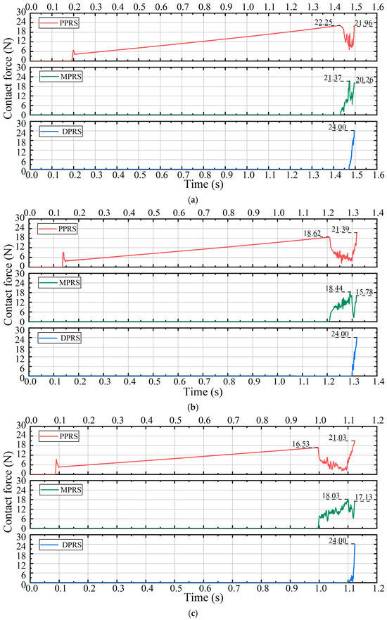
Figure 12.
Contact forces of each phalangeal region silicone during grasping. (a–c) represent the variations in contact force between each phalangeal region silicone and the apple when grasping apples of 70 mm, 80 mm, and 90 mm diameters, respectively.
It can be observed that, when grasping apples of different sizes, the contact force variation trends for the same phalangeal region silicone are similar. At the start of the grasp, the PPRS first contacts the apple, and the contact force increases gradually; when reaching 22.25 N, 18.62 N, and 16.53 N, respectively, a rapid drop occurs as the MPRS contacts the fruit surface and shares the PPRS load. Similarly, when the MPRS contact force reaches 21.39 N, 18.44 N, and 18.03 N, the contact between the DPRS and the apple redistributes the load and causes a synchronous drop in MPRS contact force. After the DPRS contacts the apple, its contact force rises rapidly, terminating the drive when the pre-set threshold of 24 N is reached. During the continued increase in DPRS contact force, the PPRS and DPRS form a clamping structure around the apple, which further increases the DPRS contact force. Upon achieving a stable enclosure, the PPRS–apple contact forces are recorded as 21.96 N, 21.39 N, and 21.03 N for the small, medium, and large apples, respectively.
To quantitatively evaluate the uniformity of force distribution among the phalanges (DPRS, MPRS, PPRS), the Coefficient of Variation (CV) of the maximum contact forces during stable grasping was calculated. The calculation results show that the CV values for apples with diameters of 70 mm, 80 mm, and 90 mm are 6.15%, 13.07%, and 14.20%, respectively. All CV values are maintained within a relatively low range (<15%), indicating that the adaptive linkage mechanism effectively distributes the gripping load across the entire finger, thereby preventing local stress concentration even when grasping fruits of varying sizes.
An analysis of Figure 11 and Figure 12 indicates that, with increasing apple size, the contact force between the flexible silicone and the apple at the stable enveloping stage decreases. This behavior is influenced by the torsion springs integrated between the joints. As the grasped object becomes larger, the final torsion angles of all joints show a pronounced reduction. According to Equation (24), it follows that a greater torsion angle yields higher torque from the torsion spring. Given that the instantaneous effective force arm during grasping remains constant, the lever principle dictates that the torque generated by the torsion spring must be counterbalanced by the moment produced by the phalangeal contact force , thereby necessitating an increase in .
where denotes the torque of the torsion spring, represents the stiffness coefficient of the torsion spring, and is the torsion angle of the torsion spring.
The simulation results indicate that, when the silicone contact force at the distal phalanges of the end-effector fingers is set to , the resultant force of the three fingers, together with the friction generated between the flexible silicone and the fruit peel surface, can provide a contact force during stable grasping that exceeds the level required for torsional detachment, thereby achieving separation of the apple from the branch. This force level is chosen to balance the feasibility of the harvesting task with the need to prevent peel damage.
3.1.3. Analysis of Grasping Contact Stress
In this study, the flexible silicone acted as the contact unit between the end-effector fingers and the apples. Its stress distribution during grasping not only determined the stability of the grasp but also directly influenced the risk of apple damage. Figure 13 shows the von Mises stress distribution of the end-effector’s flexible silicone when grasping small, medium, and large apples, at the moments when each flexible silicone’s contact force reached its maximum and when a stable grasp was achieved.
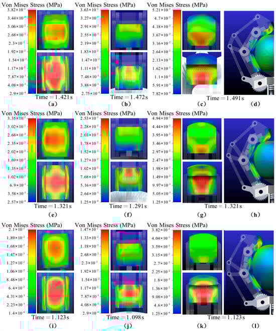
Figure 13.
Von Mises stress maps during grasping of apples of different sizes. (a–c,e–g,i–k) correspond to the PPRS, MPRS, and DPRS, respectively, when grasping small, medium, and large apples. In each figure, the upper part shows the silicone contact surface, and the lower part shows the silicone fixed surface. (d,h,l) correspond to the von Mises stress maps of the complete single-finger and apple assembly at the moment of stable grasping small, medium, and large apples, respectively.
From the von Mises stress maps described above, it is clearly observed that after the flexible silicone comes into contact with the apple, the contact load first acts on the contact surface between the flexible silicone and the apple, and subsequently the load is transmitted through the flexible silicone to its fixed surface. On both surfaces, the load diffuses uniformly in all directions with the contact point as the center. The maximum equivalent stress of the PPRS appears in its central region, that of the MPRS appears in its upper region, and that of the DPRS appears in its lower region. It is noteworthy that the maximum equivalent stress of the flexible silicone occurs on the fixed surface in contact with the rigid phalange, whereas the equivalent stress on the contact surface with the apple is relatively lower. This stress distribution characteristic arises because the interface between the flexible silicone and the rigid phalange was established as a fixed constraint in the simulation, ensuring that no relative sliding or separation occurs. Consequently, differences in boundary conditions and deformation compatibility exist between the two surfaces: on the contact surface, the deformation of the flexible silicone effectively disperses normal pressure and relieves shear stress; whereas on the fixed surface, the rigid phalange’s boundary constraint limits the freedom of material deformation, leading to load accumulation and significant stress concentration. These results indicate that the flexible silicone shell, through substantial deformation, effectively disperses the contact load, keeping the compressive stress on the apple’s surface low and significantly reducing the risk of plastic deformation and mechanical damage to the fruit.
Using the Adams Hot Point module, the maximum stress (SMX) and minimum stress (SMN) of the flexible silicone were extracted, as shown in Table 3. It can be seen that the maximum equivalent stress of each phalange silicone decreases with increasing apple size. The SMX of the PPRS decreases from 3.81 × 10⁻² MPa to 2.14 × 10⁻² MPa, the SMX of the MPRS decreases from 3.62 × 10⁻² MPa to 1.47 × 10⁻² MPa, and the maximum equivalent stress of the DPRS decreases from 5.21 × 10⁻² MPa to 4.49 × 10⁻² MPa. As the apple size increases, the effective contact area formed between the flexible silicone and the apple becomes larger, and consequently the spatial distribution area of the load also increases.
Table 3.
SMX and SMN of the PPRS, MPRS, and DPRS when grasping apples of different sizes.
Further analysis of the equivalent stress for each phalange flexible silicone reveals that, regardless of apple size, the SMX of the DPRS is always the highest, followed by that of the PPRS, with the MPRS being the lowest. This pattern is not only related to differences in the magnitude of the contact force but also closely associated with variations in the radius of curvature of the apple’s surface. According to previous studies, the radius of curvature of the apple is smallest at the top region and largest at the middle region [41]. The contact areas of the PPRS, MPRS, and DPRS correspond to the bottom, middle, and top regions of the apple, respectively. From the form of formula (23) derived based on Hertz contact theory, it can be seen that under the same contact force Fᵢ, areas with a smaller radius of curvature exhibit a higher stress concentration effect. The damage stress for Fuji apples is 0.125 MPa [42]; when grasping small, medium, and large apples, their maximum equivalent stresses are 0.016 MPa, 0.013 MPa, and 0.011 MPa, respectively, all occurring at the moment of stable grasping, which are far below the apple’s damage stress. Simulation results indicate that, during the grasping operation, the flexible silicone can absorb and disperse concentrated loads through deformation, and the apple remains in contact only with the flexible silicone without touching the rigid phalanges, effectively reducing the risk of apple damage.
3.2. Laboratory Grasping Experiment
The experiment was conducted in the Robotics Laboratory of the College of Mechanical and Electrical Engineering at Shihezi University, as shown in Figure 8. The three-fingered underactuated rigid-flexible coupling end-effector developed in this study was mounted on a robotic arm, which was operated to move the end-effector to a specified position for grasping apples located at fixed positions on a fruit tree. To minimize the impact of identification and positioning errors, the robotic arm was manually guided to the grasping pose for the target apple, after which the end-effector was closed to complete the grasping action. The end-effector was set to stop actuation when the contact force value measured by the DPRS reached 24 N. During the grasping process, contact force data between each flexible silicone (PPRS, MPRS, DPRS) and the apple were recorded in real-time as key indicators for evaluating the structural design and grasping performance of the end-effector.
To verify the adaptability and reliability of the end-effector against individual fruit differences, a total of 30 naturally grown apples were selected as samples for this experiment. These samples were categorized into three groups based on equatorial diameter, small (69–73 mm), medium (78–82 mm), and large (88–92 mm), with each group containing 10 different apples.
Figure 14a–c shows the contact force curves between each flexible silicone and the apple over time during the grasping of small (73 mm), medium (81 mm), and large (92 mm) apples (data shown here are from one representative trial in each size group). It should be noted that the apples used in the experiment were naturally harvested samples, and their size and shape differed slightly from the apple models in the simulation; thus, they were not perfectly identical. When grasping apples of different sizes, the contact sequence of the flexible silicones with the apple was consistently PPRS first, followed by MPRS, and finally DPRS, which aligns with the motion logic of the underactuated transmission chain design and is consistent with the simulation results. In these representative trials, stable enveloping grasping was achieved at 1.43 s, 1.30 s, and 1.20 s for the small, medium, and large apples, respectively.
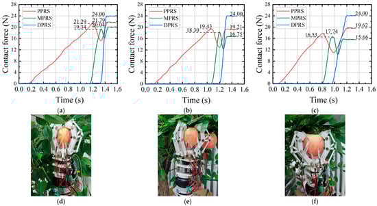
Figure 14.
Laboratory tests. (a–c) show the contact force curves between the PPRS, MPRS, and DPRS of a single finger and the apple when grasping small, medium, and large apples (data correspond to a representative trial for each size group); (d–f) show the enveloping postures of the end-effector after completing the grasp when grasping small, medium, and large apples, respectively.
Regarding the trend of contact force changes, the obtained curves all exhibited typical segmented rising characteristics. That is, after the PPRS contacted the apple, whenever another flexible silicone made contact, the contact force between the already contacting flexible silicone and the apple decreased synchronously, subsequently entering a phase of adaptive force distribution. In the typical grasping process described above, for the small apple, the contact forces between the flexible silicones (PPRS, MPRS, and DPRS) and the apple finally stabilized at 21.79 N, 20.04 N, and 24.00 N, respectively. For the medium apple, the contact forces stabilized at 19.21 N, 16.75 N, and 24.00 N, respectively. For the large apple, the contact forces stabilized at 19.62 N, 15.66 N, and 24.00 N, respectively. Throughout the grasping process, the contact force never exceeded the preset threshold of 24.00 N, and no damage was observed on the surface of any of the 30 apple samples after the tests. This demonstrates that the structural design of the end-effector proposed in this study, combined with the control system, effectively prevented the contact force between the end-effector and the apple from exceeding the damage threshold. Furthermore, throughout the experiment, the bonding interface between the silicone contact pads and the nylon phalanges remained intact, with no obvious peeling or slippage observed.
The grasping performance of the end-effector for target apples of different sizes was evaluated by comparing the simulation results with experimental data (mean ± SD)—including the grasping time and the average maximum contact forces (based on the statistical mean of 30 samples) between the apple and the PPRS/MPRS. Simultaneously, the accuracy and reliability of the simulation model in predicting contact forces were verified. The specific verification results are shown in Table 4.
Table 4.
Simulation and experimental result verification.
The Mean Absolute Percentage Error (MAPE) for contact force was 5.98%, and the MAPE for grasping time was 5.40%. These results confirm that the simulation model is both accurate and reliable. The relative errors primarily stem from the inherent geometric variability of naturally grown apples, which differ slightly from the idealized models used in the simulation, as well as the internal mechanical friction of the end-effector structure that was not accounted for in the simulation environment.
Furthermore, based on the analysis in Section 2.6, under the geometric and material configuration of the current three-fingered underactuated structure (three fingers spaced 120° apart, silicone pad friction coefficient ), as long as the contact force of the DPRS of the end-effector fingers does not exceed the preset value , the friction generated by the three fingers during grasping is already sufficient to provide the friction required for torsional detachment. This indicates that under the existing design and material parameters, this contact force threshold not only prevents damage to the fruit peel but also ensures the ability to separate the fruit from the branch, thereby meeting the dual goals of safety and efficient harvesting.
3.3. Performance Comparison
To comprehensively evaluate the performance of the proposed end-effector, a detailed comparative analysis was conducted against three representative types of apple harvesting end-effectors developed in recent years. Table 5 summarizes the key performance indicators evaluated, highlighting the distinct advantages of the proposed design in balancing efficiency and safety.
Table 5.
Performance comparison of end-effectors.
The comparative analysis demonstrates that the proposed rigid-flexible coupled underactuated structure effectively satisfies the dual requirements of harvesting efficiency and damage-free operation. The rigid structure ensures mechanical strength while enhancing transmission efficiency and controllability, thereby enabling rapid fruit enveloping. Simultaneously, the coupling of flexible silicone layers with the rigid underactuated transmission, integrated with a real-time force feedback control system, effectively prevents fruit damage. These combined advantages provide a robust foundation for achieving efficient and non-destructive harvesting.
4. Conclusions
This work addresses the demand for non-destructive grasping in the end-effector of an apple-picking robot. Considering the mechanical characteristics of apples and applying the design philosophy of underactuated rigid–flexible coupling, we developed a novel underactuated rigid–flexible coupling end-effector. A comprehensive investigation encompassing structural optimization, simulation-based analysis, and experimental validation was conducted. The main conclusions are as follows:
This study addresses the critical trade-off between grasping stability and fruit safety in apple harvesting by developing a novel underactuated rigid–flexible coupled end-effector. Through genetic algorithm-based structural optimization and the integration of active force feedback control, the device demonstrated excellent adaptability to apples of varying sizes. Crucially, the design leverages the synergy of its components: the underactuated rigid structure ensures sufficient structural stiffness to transmit the torsional torque required for stem detachment, while the flexible silicone combined with the real-time force feedback control system enables precise contact force control between the end-effector and the apple, effectively preventing fruit damage. Both simulation and experimental results indicate that the end-effector proposed in this study can effectively maintain the contact force below the critical damage threshold, while generating sufficient friction to achieve torsional detachment of the fruit, thereby achieving an optimal balance between high grasping stability and non-destructive harvesting.
While the experimental results in the laboratory have demonstrated the effectiveness and reliability of the proposed end-effector, real orchard environments introduce environmental interferences. Factors such as clustered fruit growth, foliage occlusion, and complex fruit growth postures may have a certain impact on the performance of the end-effector.
In future work, we will further optimize the performance of the end-effector and conduct research on fruit detachment methods and precise positioning of the end-effector, in order to improve the harvesting efficiency of the picking robot.
Author Contributions
Conceptualization, Z.Z. and J.L.; methodology, Z.Z. and J.L.; validation, Y.L. (Yingjie Li); formal analysis, Z.L. and Y.L. (Yingjie Li); data curation, Z.L. and G.H.; investigation, Z.L., Y.L. (Yufeng Li) and G.H.; writing—original draft preparation, Z.L. and Y.L. (Yufeng Li); writing—review and editing, Z.Z., J.L. and H.D.; supervision, Z.Z., J.L. and X.W.; funding acquisition, J.L. and Z.Z. All authors have read and agreed to the published version of the manuscript.
Funding
This work was funded by Project of Tianchi Talented Young Doctor (Grant No. CZ002558) and Xinjiang Fruit Industry Technology System (Grant No. XJLGCYJSTX04-2025), and Supported by the State Key Laboratory of Mechanical System and Vibration (Grant No. MSV202417).
Institutional Review Board Statement
Not applicable.
Data Availability Statement
Data are contained within the article.
Conflicts of Interest
The authors declare no conflicts of interest.
References
- Jeong, H.; Choi, C. Adaptive Supply Chain System Design for Fruit Crops under Climate Change. Systems 2023, 11, 514. [Google Scholar] [CrossRef]
- Miao, Y.; Zheng, J. Optimization design of compliant constant-force mechanism for apple picking actuator. Comput. Electron. Agric. 2020, 170, 105232. [Google Scholar] [CrossRef]
- Bao, X.; Ma, Z.; Ma, X.; Li, Y.; Ren, M.; Li, S. Design and Experiment of a Citrus Picking Robot under Natural Conditions in Hilly Orchards. Trans. Chin. Soc. Agric. Mach. 2024, 55, 124–135. [Google Scholar]
- Ji, W.; He, G.; Xu, B.; Zhang, H.; Yu, X. A new picking pattern of a flexible three-fingered end-effector for apple harvesting robot. Agriculture 2024, 14, 102. [Google Scholar] [CrossRef]
- Jia, W.; Tian, Y.; Luo, R.; Zhang, Z.; Lian, J.; Zheng, Y. Detection and segmentation of overlapped fruits based on optimized mask R-CNN application in apple harvesting robot. Comput. Electron. Agric. 2020, 172, 105380. [Google Scholar] [CrossRef]
- Graham, S.S.; Zong, W.; Feng, J.; Tang, S. Design and testing of a kiwifruit harvester end-effector. Trans. ASABE 2018, 61, 45–51. [Google Scholar] [CrossRef]
- Bac, C.W.; Hemming, J.; Van Tuijl, B.; Barth, R.; Wais, E.; van Henten, E.J. Performance evaluation of a harvesting robot for sweet pepper. J. Field Robot. 2017, 34, 1123–1139. [Google Scholar] [CrossRef]
- Kondo, N.; Yamamoto, K.; Shimizu, H.; Yata, K.; Kurita, M.; Shiigi, T.; Monta, M.; Nishizu, T. A machine vision system for tomato cluster harvesting robot. Eng. Agric. Environ. Food 2009, 2, 60–65. [Google Scholar] [CrossRef]
- Han, C.; Lv, J.; Dong, C.; Li, J.; Luo, Y.; Wu, W.; Abdeen, M.A. Classification, advanced technologies, and typical applications of end-effector for fruit and vegetable picking robots. Agriculture 2024, 14, 1310. [Google Scholar] [CrossRef]
- Zhang, K.; Lammers, K.; Chu, P.; Li, Z.; Lu, R. System design and control of an apple harvesting robot. Mechatronics 2021, 79, 102644. [Google Scholar] [CrossRef]
- Han, S.; Zhang, Z.; Zhang, H.; Zhang, Y.; Wang, Z. Design and Simulation Analysis of the End-Effector for Round Fruit Picking Robot. J. Mach. Des. 2019, 36, 82–85. [Google Scholar]
- Ma, Z.; Yan, H.; Tai, L.; Du, X. Optimization Design and Test of Occlusal-type Citrus Picking End-effector. Trans. Chin. Soc. Agric. Mach. 2024, 55, 106–115+125. [Google Scholar]
- Wang, Y.; Fang, S.; Zhao, Z.; Ma, J.; Xu, H. Design and Experiment of End-Effector for Citrus Picking Robot. Chin. Agric. Sci. Bull. 2018, 34, 69–77. [Google Scholar]
- Hu, G.; Chen, C.; Chen, J.; Sun, L.; Sugirbay, A.; Chen, Y.; Jin, H.; Zhang, S.; Bu, L. Simplified 4-DOF manipulator for rapid robotic apple harvesting. Comput. Electron. Agric. 2022, 199, 107177. [Google Scholar] [CrossRef]
- Valk, T.A.; Mouton, L.J.; Otten, E.; Bongers, R.M. Synergies reciprocally relate end-effector and joint-angles in rhythmic pointing movements. Sci. Rep. 2019, 9, 17378. [Google Scholar] [CrossRef]
- Fujinaga, T.; Yasukawa, S.; Ishii, K. Development and evaluation of a tomato fruit suction cutting device. In Proceedings of the 2021 IEEE/SICE International Symposium on System Integration (SII), Iwaki, Japan, 11–14 January 2021; pp. 628–633. [Google Scholar]
- Zhou, K.; Xia, L.; Liu, J.; Qian, M.; Pi, J. Design of a flexible end-effector based on characteristics of tomatoes. Int. J. Agric. Biol. Eng. 2022, 15, 13–24. [Google Scholar] [CrossRef]
- Liu, J.; Li, P.; Li, Z. A multi-sensory end-effector for spherical fruit harvesting robot. In Proceedings of the 2007 IEEE International Conference on Automation and Logistics, Jinan, China, 18–21 August 2007; pp. 258–262. [Google Scholar]
- Jun, J.; Kim, J.; Seol, J.; Kim, J.; Son, H.I. Towards an efficient tomato harvesting robot: 3D perception, manipulation, and end-effector. IEEE Access 2021, 9, 17631–17640. [Google Scholar] [CrossRef]
- De Luca, A.; Mattone, R.; Oriolo, G. Steering a class of redundant mechanisms through end-effector generalized forces. IEEE Trans. Robot. Autom. 2002, 14, 329–335. [Google Scholar] [CrossRef]
- Wang, T.; Du, W.; Zeng, L.; Su, L.; Zhao, Y.; Gu, F.; Liu, L.; Chi, Q. Design and testing of an end-effector for tomato picking. Agronomy 2023, 13, 947. [Google Scholar] [CrossRef]
- Ju, C.; Kim, J.; Seol, J.; Son, H.I. A review on multirobot systems in agriculture. Comput. Electron. Agric. 2022, 202, 107336. [Google Scholar] [CrossRef]
- Yu, L.; Yu, G.; Wang, H.; Sun, F.; Qian, M. Design and experiment of the end-effector with underactuated articulars for citrus picking. Trans. Chin. Soc. Agric. Eng. 2023, 39, 29–38. [Google Scholar]
- Zheng, Y.; Pi, J.; Guo, T.; Xu, L.; Liu, J.; Kong, J. Design and simulation of a gripper structure of cluster tomato based on manual picking behavior. Front. Plant Sci. 2022, 13, 974456. [Google Scholar] [CrossRef]
- Kam, J.; Vargas, A.M.; Coltin, B. An underactuated rigid-soft hybrid gripper prototype for conforming free-flying manipulation. In Proceedings of the IEEE International Conference on Robotics and Automation, Atlanta, GA, USA, 19–23 May 2025. [Google Scholar]
- Lee, K.; Wang, Y.; Zheng, C. Twister hand: Underactuated robotic gripper inspired by origami twisted tower. IEEE Trans. Robot. 2020, 36, 488–500. [Google Scholar] [CrossRef]
- Su, C.; Wang, R.; Lu, T.; Wang, S. SAU-RFC hand: A novel self-adaptive underactuated robot hand with rigid-flexible coupling fingers. Robotica 2023, 41, 511–529. [Google Scholar] [CrossRef]
- Fu, H.; Yang, J.; Du, W.; Wang, W.; Liu, G.; Yang, Z. Determination of coefficient of restitution of fresh market apples caused by fruit-to-fruit collisions with a sliding method. Biosyst. Eng. 2022, 224, 183–196. [Google Scholar] [CrossRef]
- Li, Z.; Liu, J.; Li, P. Relationship between Mechanical Properties and Mechanical Damage of Tomatoes in Robotic Harvesting. Trans. Chin. Soc. Agric. Eng. 2010, 26, 112–116. [Google Scholar]
- Fu, H.; He, L.; Ma, S.; Karkee, M.; Chen, D.; Zhang, Q.; Wang, S. ‘Jazz’ apple impact bruise responses to different cushioning materials. Trans. ASABE 2017, 60, 327–336. [Google Scholar] [CrossRef]
- Studman, C.; Brown, G.; Timm, E.; Schulte, N.; Vreede, M. Bruising on blush and non-blush sides in apple-to-apple impacts. Trans. ASAE 1997, 40, 1655–1663. [Google Scholar] [CrossRef]
- Liu, X.; Cao, Z.; Yang, L.; Chen, H.; Zhang, Y. Research on damage properties of apples based on static compression combined with the finite element method. Foods 2022, 11, 1851. [Google Scholar] [CrossRef]
- Birglen, L.; Gosselin, C.M. Kinetostatic analysis of underactuated fingers. IEEE Trans. Robot. Autom. 2004, 20, 211–221. [Google Scholar] [CrossRef]
- Huang, H.; Wang, R.; Huang, F.; Chen, J. Analysis and realization of a self-adaptive grasper grasping for non-destructive picking of fruits and vegetables. Comput. Electron. Agric. 2025, 232, 110119. [Google Scholar] [CrossRef]
- Meng, H.; Yang, K.; Zhou, L.; Shi, Y.; Cai, S.; Bao, G. Optimal design of linkage-driven underactuated hand for precise pinching and powerful grasping. IEEE Robot. Autom. Lett. 2024, 9, 3475–3482. [Google Scholar] [CrossRef]
- Zhu, J. Compression Damage and Quality Deterioration Mechanism of ‘Fuji’ Apple Fruit. Master’s Thesis, Anhui Agricultural University, Hefei, China, 2022. [Google Scholar]
- Bu, L.; Chen, C.; Hu, G.; Zhou, J.; Sugirbay, A.; Chen, J. Investigating the dynamic behavior of an apple branch-stem-fruit model using experimental and simulation analysis. Comput. Electron. Agric. 2021, 186, 106224. [Google Scholar] [CrossRef]
- Bu, L. Key Technologies of Robotic Apple Harvester in Constructed Orchard. Ph.D. Thesis, Northwest A&F University, Yangling, China, 2021. [Google Scholar]
- Bu, L.; Hu, G.; Chen, C.; Sugirbay, A.; Chen, J. Experimental and simulation analysis of optimum picking patterns for robotic apple harvesting. Sci. Hortic. 2020, 261, 108937. [Google Scholar] [CrossRef]
- Sun, J.; Sun, L.; Zhao, G.; Liu, J.; Chen, Z.; Jing, L.; Cao, X.; Zhang, H.; Tang, W.; Wang, J. Triboelectric force feedback-based fully actuated adaptive apple-picking gripper for optimized stability and non-destructive harvesting. Comput. Electron. Agric. 2025, 237, 110725. [Google Scholar] [CrossRef]
- Fu, H.; Du, W.; Yang, J.; Wang, W.; Wu, Z.; Yang, Z. Bruise measurement of fresh market apples caused by repeated impacts using a pendulum method. Postharvest Biol. Technol. 2023, 195, 112143. [Google Scholar] [CrossRef]
- Li, Y.; Du, X.; Wang, J.; Chai, L. Mechanical Properties of Apple Picking Damage. Agric. Eng. 2018, 8, 77–80. [Google Scholar]
- Wang, X.; Kang, H.; Zhou, H.; Au, W.; Wang, M.Y.; Chen, C. Development and evaluation of a robust soft robotic gripper for apple harvesting. Comput. Electron. Agric. 2023, 204, 107552. [Google Scholar] [CrossRef]
- Chen, K.; Li, T.; Yan, T.; Xie, F.; Feng, Q.; Zhu, Q.; Zhao, C. A soft gripper design for apple harvesting with force feedback and fruit slip detection. Agriculture 2022, 12, 1802. [Google Scholar] [CrossRef]
- Silwal, A.; Davidson, J.R.; Karkee, M.; Mo, C.; Zhang, Q.; Lewis, K. Design, integration, and field evaluation of a robotic apple harvester. J. Field Robot. 2017, 34, 1140–1159. [Google Scholar] [CrossRef]


Disclaimer/Publisher’s Note: The statements, opinions and data contained in all publications are solely those of the individual author(s) and contributor(s) and not of MDPI and/or the editor(s). MDPI and/or the editor(s) disclaim responsibility for any injury to people or property resulting from any ideas, methods, instructions or products referred to in the content. |
© 2026 by the authors. Licensee MDPI, Basel, Switzerland. This article is an open access article distributed under the terms and conditions of the Creative Commons Attribution (CC BY) license.