


Abstract
The launch bar is a unique device of carrier-based aircraft, which is connected to the nose gear and shuttle. In order to avoid the launch bar striking the flight deck after the launch bar pops out of the shuttle, it is very important to research the dynamics performance of the launch bar. This paper establishes a staged mathematical model of catapult launch including the launch bar, a steam-powered catapult, a holdback bar, and a carrier-based aircraft. This article studied the effect of the mass of the launch bar, restoring moment of the launch bar, and center of gravity position of the launch bar on the dynamics performance of the launch bar. The results showed the following: (1) we could reduce the risk collision of the launch bar and deck by reducing the mass of the launch bar, increasing the restoring moment, and shifting the center of gravity position of the launch bar; (2) under the working condition of this article, we changed the center of gravity position of the launch bar to control the sink of the launch bar end, having the most obvious effect, and we reduced the mass of the launch bar, having the least effect on controlling the sink of the launch bar end; however, reducing the mass of the launch bar could also greatly reduce the risk collision of the launch bar and deck; (3) in order to avoid the launch bar striking the flight deck, the restoring moment of the launch bar must overcome the sum of other moments. The study results can give a theoretical reference for designing and testing the launch bars of carrier-based aircraft. It can also give a theoretical reference for designing and testing the launch bar’s driving mechanisms.
1. Introduction
The main role of the launch bar is to transmit the catapult force [1,2,3] to the aircraft, allowing the aircraft to accelerate while taxiing before reaching a safe catapult end airspeed within the limited length deck. At the end of the catapult [4,5,6], the launch bar pops out of the shuttle. The launch bar, which is in the air, needs a mechanism for controlling and overcoming other damping torque. The launch bar may strike the flight deck if the restoring moment of the launch bar cannot overcome the other damping torque. Therefore, restraining the contrarotation of the launch bar is an important condition when ensuring the secure catapult launch of an aircraft. It is very important to research the characteristics of launch bar dynamics.
When researching the launch bar for a catapult launch, Reference [7] indicated that the launching system should consist of launch bar installation, cockpit controls and components, and holdback and release installation. Small [8] studied full-scale tests of nose tow catapulting, and showed that nose wheel tow catapulting was better than a bridle launching system. Reference [9] established a six-degree-of-freedom dynamics model of a catapult launch for carrier-based aircraft taking into consideration aircraft off-center position, and the launch bar load was calculated. Reference [10] carried out parametric models and optimization analyses of launch bar driving mechanisms. There were some patents introduced concerning the installation of launch bars, for example, (a) an improved power-operated launching system for aircraft [11]; (b) launching and holdback gear designed around the nose landing gear of the aircraft [12]; (c) a launch bar pivotally mounted on the oleo strut torque links [13]; (d) a control mechanism for controlling a catapult bar [14]; and (e) a nose gear assembly using one nose wheel for a catapult-launched airplane [15]. However, there is no literature on the characteristics of launch bar dynamics after the launch bar automatically disengages from the shuttle at the end of the power stroke.
On the basis of the security of a catapult launch for carrier-based aircraft, Reference [8] indicated that nose wheel tow would increase the safety of the flight deck. Lucas [16] researched catapult criteria for carrier-based airplanes. Many studies were carried out on the problem of the main gear’s off-center location for the catapult launch of carrier-based aircraft [7,9,17,18,19,20]. Reference [21] indicated that the catapult minimum end airspeed was the airspeed value that could be safely tested aboard an aircraft carrier. In Reference [22], a total of 39 launching tests were performed during the first test campaign; the conclusion was that the launch bar retraction system had to be improved. Further research on catapult launch mainly focused on the effect of deck motion [23,24,25], the control problems of the climbing stage [26,27,28,29], the effect of nose landing gear’s sudden extension [30,31,32], the analysis of aircraft–carrier parameter matching [33,34], and so on. However, despite all public documents in regard to catapult launch around the world, there is a lack of research on the effect of the characteristics of launch bar dynamics on the security of the catapult launch after the launch bar automatically disengages from the shuttle at the end of the power stroke.
This paper made great efforts toward the goal of analyzing the characteristics of launch bar dynamics. This article built a mathematical model of catapult launch, including a launch bar dynamics model, and analyzed the effect of some factors on the characteristics of launch bar dynamics, such as the mass of the launch bar, the center of gravity position of the launch bar, and the restoring moment of the launch bar. The main contributions of this paper are as follows: (1) a complete mathematical model of catapult launch used for analyzing the characteristics of launch bar dynamics character was established; (2) the effects of some factors on the characteristics of launch bar dynamics were analyzed, providing a theoretical reference for the relevant design of launch bars.
2. Mathematical Model of Catapult Launch
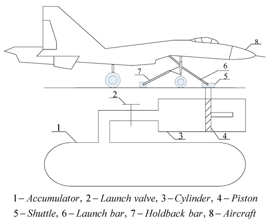
A steam catapult launch system for carrier-based aircraft is made up of a steam-powered catapult, a towing holdback device, and the carrier-based aircraft, and its simplified model is presented in Figure 1. The distinct parameters of the catapult launch process of carrier-based aircraft can be found in Reference [35].
Figure 1.
The general steam-powered catapult launch system for carrier-based aircraft.
2.1. Modeling Assumptions
In order to research the basic law of motion for a launch bar during the process of a catapult launch, this article made the following assumptions:
- The thermodynamic process of the steam catapult is an adiabatic process; the steam in the catapult is not affected by its environment.
- The accumulator, cylinder, and piston are rigid bodies, neglecting any changes in shape caused by temperature and pressure.
- The thermodynamic processes of the accumulator and cylinder are quasi-static processes.
- The steam has no friction with the pipe wall during the progress from accumulator to cylinder.
- The fuselage of the carrier-based aircraft is a rigid body.
- The deck motion and airflow interference are neglected.
- The carrier-based aircraft has no yaw angle during the process of catapult launch.
- The effects of asymmetric factors are not considered during the process of catapult launch.
- The nose gear is vertical with the flight deck surface of the carrier during the process of catapult launch.
- The elevator angle is fixed during the whole process of catapult launch.
- The force and damper model of the nose gear adopts the classical two-mass spring–damper model which divides the aircraft into two parts: the elastic support mass [36] and the inelastic support mass.
2.2. Mathematical Model of the Launch Bar
2.2.1. The Mathematical Model of the Launch Bar before the Launch Bar Automatically Disengages
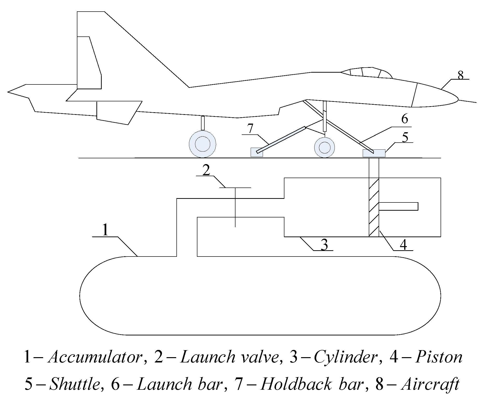
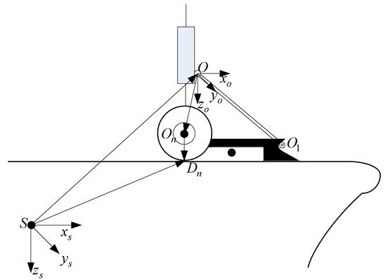
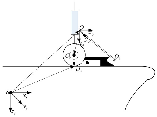
The launch bar is connected with the nose gear and shuttle before the launch bar automatically disengages, as presented in Figure 2.
Figure 2.
The engagement system of the launch bar, nose gear, and shuttle.
In Figure 2, is the carrier-body coordinate system which is fixed with the carrier. The origin is placed at the center of gravity of the carrier. Axis is parallel with the deck surface of the carrier and points to the prow. Axis is in the carrier symmetry plane and points to the bottom, and axis is perpendicular to the carrier symmetry plane and points to the starboard. The point is the pivot point of the launch bar. is the pivot point coordinate system which is fixed with the nose gear. Axis is perpendicular to the nose gear and points to the front. Axis is parallel with the nose gear and points downward, and axis follows the right-hand rule. Point is the center of gravity of the tire of the nose gear. Point is the contact point of the deck and the tire of the nose gear.
According to the geometrical relationship between the launch bar and nose gear, we can get the equation of the center of gravity (cg) position of the launch bar as follows:
where is the coordinate of the pivot point, is a proportionality factor which is defined as the distance from the cg position of the launch bar to the pivot point divided by the length of the launch bar, is the length of the launch bar, and is the angle between the launch bar axis and the deck.
According to the geometrical relationship between the launch bar and nose gear, we can get the equation of the end of the launch bar as follows:
The steam catapult transmits the load to the nose gear via the launch bar; thus, the axial load of the launch bar can be divided into two parts: the catapult force which is parallel with the deck, and the force which is vertical with respect to the deck; they are given by
where is the axial load of the launch bar.
2.2.2. The Mathematical Model of the Launch Bar after the Launch Bar Automatically Disengages
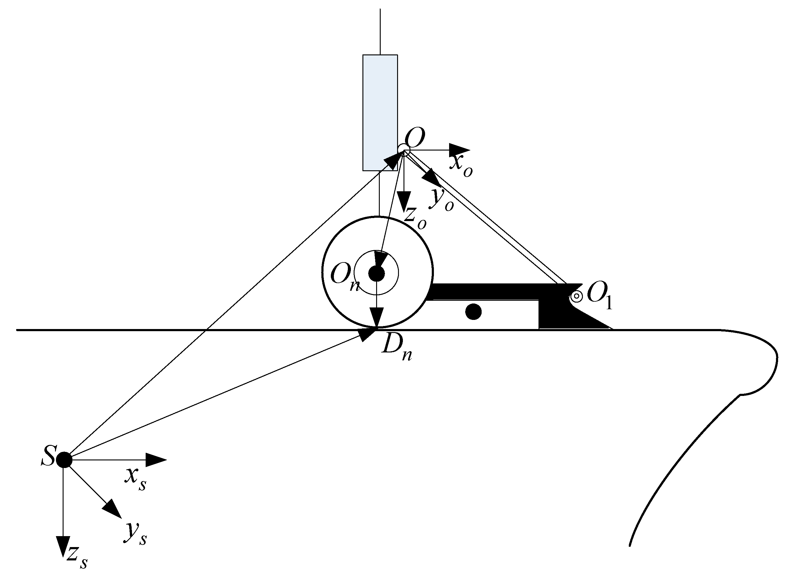
At the end of the catapult, the launch bar pops out of the shuttle, as presented in Figure 3.
Figure 3.
The system of the launch bar, nose gear, and shuttle.
The equation of the cg position of the launch bar is as follows:
where is the angle between the launch bar and nose gear.
Because the pivot point coordinate system is parallel to the carrier-body coordinate system, the equation of the momentum theorem for the launch bar is given by
where is the restoring moment of the launch bar, is the moment of gravity of the launch bar, is the moment of the force of inertia due to the longitudinal acceleration of the pivot point, is the moment of the force of inertia due to the nose landing gear’s sudden extension, is the moment of inertia of the launch bar, and is the angular acceleration of the launch bar.
The equation of the angle between the launch bar and nose gear is as follows:
where is the initial angle between the launch bar and nose gear, and is the change value of the angle between the launch bar and nose gear.
The equation of the restoring moment of the launch bar is as follows:
where is the restoring moment of the launch bar, which is a constant in this article.
The equation of the moment of gravity of the launch bar is as follows:
where is the mass of the launch bar, and is the acceleration due to gravity.
The equation of the moment of the force of inertia due to the longitudinal acceleration of the pivot point is as follows:
where is longitudinal acceleration of the aircraft.
The equation of the moment of the force of inertia due to the nose landing gear’s sudden extension is as follows:
where is the vertical acceleration of the elastic support mass.
The vertical acceleration of the elastic support mass can be calculated as follows:
where is the elastic support mass of the nose gear, is the air spring force of the nose gear, is the strut friction force of the nose gear, is the hydraulic damping force of the nose gear, is the equivalent aerodynamic lift acting on the nose gear, and is the gear stroking velocity of the nose gear.
The air spring force can be calculated as follows:
where is the effective area of pressure in the air chamber, is the initial pressure of air in the chamber, is the initial volume of air in the chamber, is the stroke of the damper, is gas polytropic index which varies between 1.1 and 1.4, and is the air pressure.
The equation for calculating the hydraulic damping force is shown below.
where is the density of the oil, is the coefficient of contraction of the main oil chamber, is the coefficient of contraction of the back oil chamber, is the area of oil pressure of the main oil chamber, is the area of oil pressure of the back oil chamber, is the oil hole area of the main oil chamber, and is the oil hole area of the back oil chamber.
The strut friction force of the nose gear is displayed below.
where is the friction coefficient of the leather cup, is the bending friction coefficient of the damper, is the normal force of the upper supporting points when the damper bends, and is the normal force of the lower supporting points when the damper bends.
2.3. Mathematical Model of Other Sub-Modules
2.3.1. Mathematical Model of the Steam-Powered Catapult
The steam catapult is mainly made up of an accumulator, a launch valve, a cylinder, and a piston, as shown in Figure 1. Below, the thermodynamics model of the accumulator, the mathematical model of the launch valve, and the thermodynamics model of the cylinder are described. The thermodynamics models of the accumulator and cylinder were verified by comparison with experimental data [3,37].
We can get the differential equation of steam pressure inside the accumulator from Reference [37].
where is the ratio of specific heat, is the gas constant of steam, is the mass flow rate, is the outflow mass of steam from the accumulator, is the temperature of the accumulator, and is the volume of the accumulator.
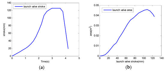
The launch valve is one of the central devices of the steam catapult launch system. The steam catapult launch system can get different catapult energies by adjusting the stroke of the launch valve and the effective launch valve opening area. In order to make the model of the launch valve mostly conform to real conditions, this article uses the test data describing the stroke of a launch valve and the effective launch valve opening area [38]. These test data are illustrated in Figure 4.
Figure 4.
(a) Launch valve stroke; (b) launch valve area.
The accumulator and cylinder thermodynamic systems are connected with each other through the mass flow rate. The formula of mass flow rate is given by
where is the equivalent effective cross-sectional area of the launch valve and the pipe between the accumulator and cylinder, is the critical pressure, and is the pressure of the cylinder.
The critical pressure can be calculated as follows:
The equivalent effective cross-sectional area of the launch valve and the pipe between the accumulator and cylinder is given by the following equation:
where is the accumulator outlet area, is the effective launch valve opening area, and is the inlet area of the cylinder.
We can get the differential equation of steam pressure inside the cylinder from Reference [37].
where is the area of the piston, is the displacement of the piston, and is the initial displacement of the piston.
The equation of the steam pressure of the piston is as follows:
where is the area of the non-steam piston, and is the gas pressure of the non-steam cylinder.
2.3.2. Mathematical Model of the Holdback Bar
The holdback bar acts on three stages: tensioning, aircraft thrust with the holdback, and catapult force build-up with the holdback. The aircraft is in a static balance condition on the deck during the above three stages, because it is affected by the holdback load of the holdback bar. The holdback bar has a minimum release element load. The holdback bar is broken when the axial load of the holdback bar reaches the minimum release load during the catapult force build-up with the holdback.
In Reference [39], the minimum release load was calculated as follows:
where is the maximum thrust of the aircraft, is the tension load, is the maximum design weight of the aircraft, and is the angle between the holdback axis and the deck at release.
The longitudinal component of the axial load of the holdback bar is as follows:
The vertical component of the axial load of the holdback bar is as follows:
2.4. Staged Mathematical Model of the Catapult Launch
The catapult launch process for carrier-based aircraft is mainly divided into nine stages. In this article, the mathematical model of the catapult launch process corresponds to the final eight stages. The mathematical model of the catapult launch process is composed of a static model of tensioning, a static model of full takeoff power, a mathematical model of catapult force build-up with the holdback, a model of release, a dynamics model of the power stroke, a dynamics model of the free deck run, and a dynamics model of fly-away [35]. The mathematical model of the steam catapult launch process of carrier-based aircraft was verified by comparison with experimental data, and the mathematical model of the minimum release load of the holdback bar was consistent with military specifications [37].
3. Results and Discussions
The simulation conditions of the catapult launch are shown in Table 1.
Table 1.
Simulation conditions of the catapult launch.
3.1. The Effect of the Launch Bar Mass on the Launch Bar Dynamics
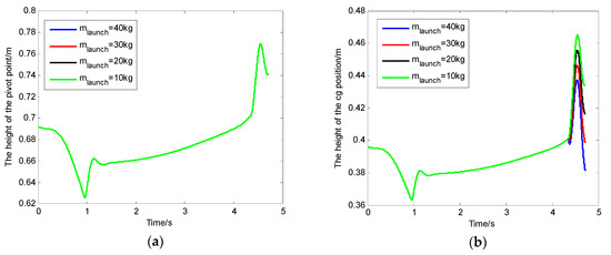
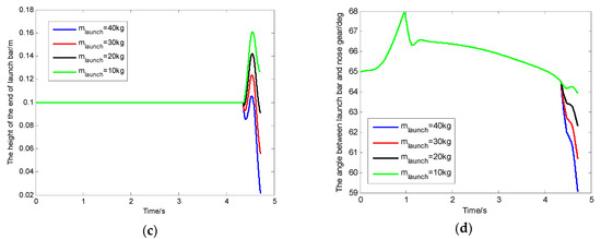
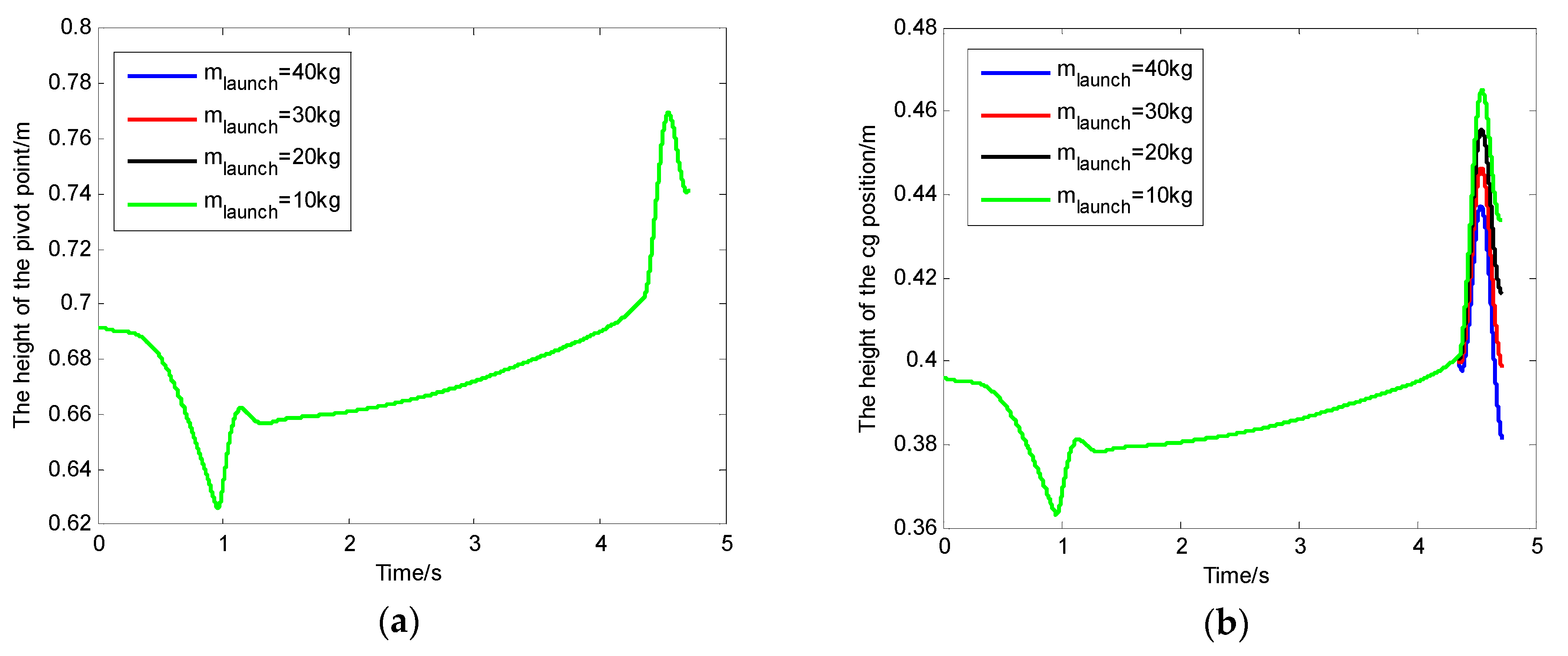
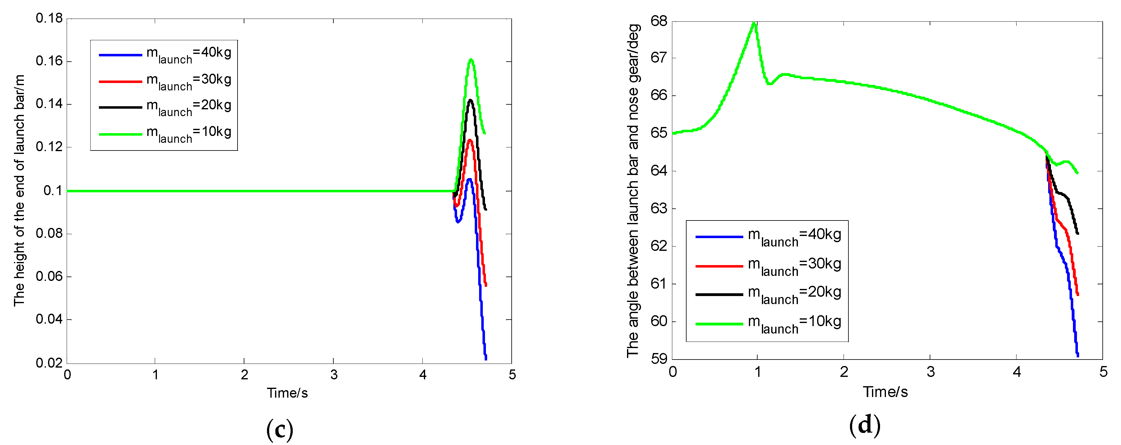
This article selected the masses of the launch bar as 10 kg, 20 kg, 30 kg, and 40 kg when the simulation was carried out. The height of the pivot point of the launch bar, the height of the cg position of the launch bar, the height of the end of the launch bar, and the angle between the launch bar and the nose gear with the change in mass of the launch bar are shown in Figure 5.
Figure 5.
(a) The height between the pivot point of the launch bar and the deck of the carrier; (b) the height between the center of gravity (cg) position of the launch bar and the deck of the carrier; (c) the height between the end of the launch bar and the deck of the carrier; (d) the angle between the launch bar and the nose gear.
After the launch bar automatically disengaged from the shuttle at the end of the power stroke, the following values are recorded in Table 2 for the different masses of the launch bar: (1) the peak value and the final value of the height between the pivot point and the deck of the carrier; (2) the peak value and the final value of the height between the cg position of the launch bar and the deck of the carrier; (3) the peak value and the final value of the height between the end of the launch bar and the deck of the carrier; (4) the final value of the angle between the launch bar and the nose gear.
Table 2.
Results of key parameters with different launch bar masses.
In Table 2, is the peak value of the height between the pivot point and the deck of the carrier, is the final value of the height between the pivot point and the deck of the carrier, is the peak value of the height between the center of gravity (cg) position of the launch bar and the deck of the carrier, is the final value of the height between the cg position of the launch bar and the deck of the carrier, is the peak value of the height between the end of the launch bar and the deck of the carrier, is the final value of the height between the end of the launch bar and the deck of the carrier, and is the final value of the angle between the launch bar and the nose gear.
The change of the launch bar mass had no effect on the height from the pivot point to the deck, as shown in Figure 5a. This phenomenon occurred because the pivot point and the nose gear were hinged, and the height from the pivot point to the deck changed along with the change in elastic support mass. Due to the mass of the launch bar being smaller than the elastic support mass, it had little effect on the dynamics of the elastic support mass. Therefore, the changeable position of the pivot point was affected by the condition of the launching system, which was at the end of the catapult, and by the performance of the nose gear after the launch bar automatically disengaged from the shuttle at the end of the power stroke.
With the increase in launch bar mass, some values were reduced after the launch bar automatically disengaged from the shuttle at the end of the power stroke, as shown in Table 2 and Figure 5: (a) the peak value and the final value of the height between the cg position of the launch bar and the deck of the carrier; (b) the peak value and the final value of the height between the end of the launch bar and the deck of the carrier; (c) the final value of the angle between the launch bar and the nose gear. This phenomenon occurred because as the launch bar mass increased, so did the moment of gravity of the launch bar and the moment of the force of inertia due to the longitudinal acceleration of the pivot point. These two moments could affect the equation of the momentum theorem for the launch bar. Finally, the increase of the launch bar mass caused the decrease of the above values.
There was an assumption that the initial height from the end of launch bar to the deck was 5 cm. When the mass of the launch bar was 40 kg, the final value of the height between the end of the launch bar and the deck of the carrier decreased by 7.88 cm, whereby the launch bar would strike the deck surface of the carrier. Therefore, the risk of the launch bar striking the deck surface can be decreased by reducing the mass of the launch bar.
3.2. The Effect of the Restoring Moment of the Launch Bar on the Launch Bar Dynamics
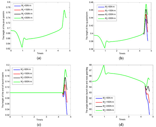
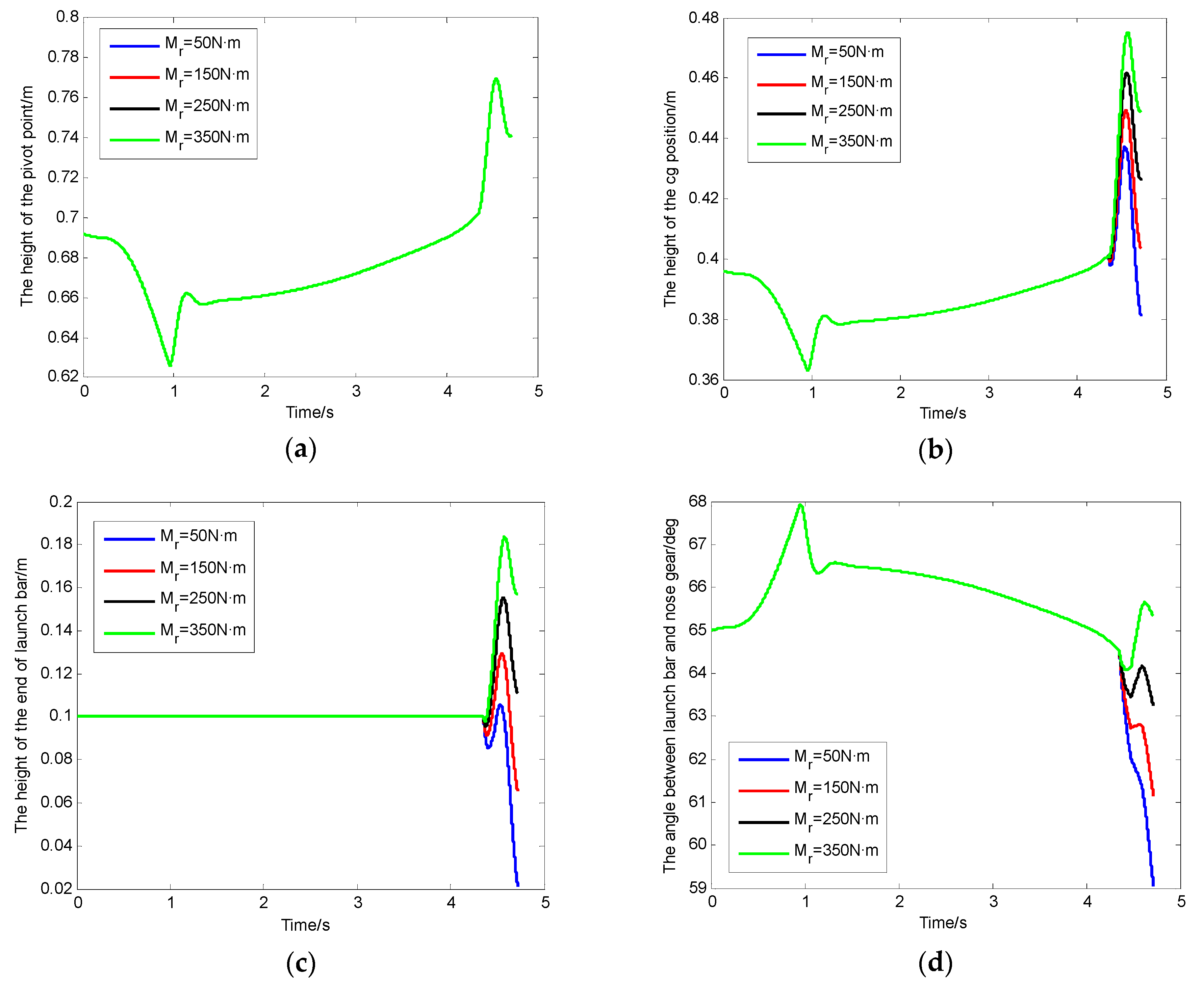
This article selected the restoring moments of the launch bar as 50 N·m, 150 N·m, 250 N·m, and 350 N·m when the simulation was carried out. The height of the pivot point of the launch bar, the height of the cg position of the launch bar, the height of the end of the launch bar, and the angle between the launch bar and the nose gear with the change in restoring moment of the launch bar are shown in Figure 6.
Figure 6.
(a) The height between the pivot point of the launch bar and the deck of the carrier; (b) the height between the cg position of the launch bar and the deck of the carrier; (c) the height between the end of the launch bar and the deck of the carrier; (d) the angle between the launch bar and the nose gear.
After the launch bar automatically disengaged from the shuttle at the end of the power stroke, the key parameters are recorded in Table 3 for different restoring moments of the launch bar.
Table 3.
Results of key parameters with different restoring moments of the launch bar.
The change in launch bar restoring moment had no effect on the height from the pivot point to the deck, as shown in Figure 6a. This phenomenon occurred because the restoring moment of the launch bar was smaller than the load in the catapult launch system. Therefore, the change in launch bar restoring moment had little effect on the dynamics of the elastic support mass.
Upon increasing the restoring moment of the launch bar, the following values increased after the launch bar automatically disengaged from the shuttle at the end of the power stroke: (a) the peak value and the final value of the height between the cg position of the launch bar and the deck of the carrier; (b) the peak value and the final value of the height between the end of the launch bar and the deck of the carrier; (c) the final value of the angle between the launch bar and the nose gear. This phenomenon occurred because the launch bar restoring moment could affect the equation of the momentum theorem for the launch bar, whereby a larger launch bar restoring moment resulted in a larger angular acceleration of the launch bar. The risk of collision between the launch bar and the deck can be reduced by increasing the restoring moment.
There was an assumption that the initial height from the end of the launch bar to the deck was 5 cm. When the restoring moment of the launch bar was 50 N·m, the final value of the height between the end of the launch bar and the deck of the carrier decreased by 7.88 cm, whereby the launch bar would strike the deck surface of the carrier. Therefore, the risk of the launch bar striking the deck surface can be decreased by increasing the restoring moment of the launch bar.
3.3. The Effect of the Launch Bar CG Position on the Launch Bar Dynamics
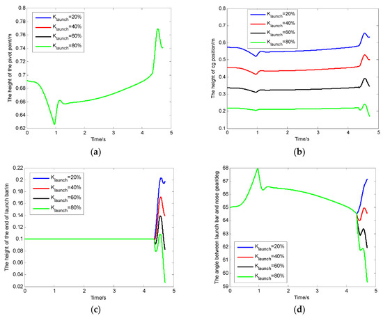
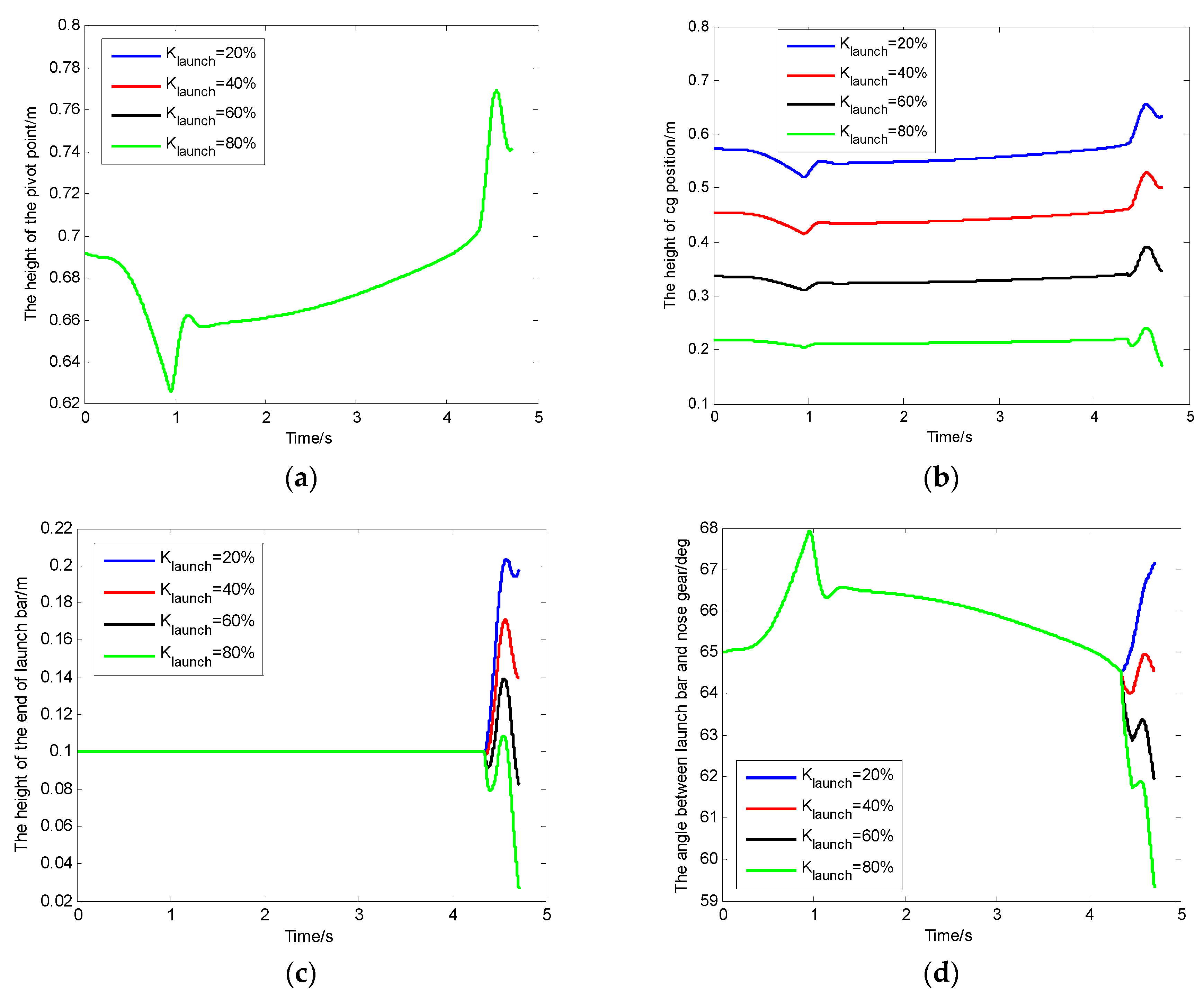
This article selected the proportionality factor () of the launch bar as 20%, 40%, 60%, and 80% when the simulation was carried out. The height of the pivot point of the launch bar, the height of the cg position of the launch bar, the height of the end of the launch bar, and the angle between the launch bar and the nose gear with the change in proportionality factor of the launch bar are shown in Figure 7.
Figure 7.
(a) The height between the pivot point of the launch bar and the deck of the carrier; (b) the height between the cg position of the launch bar and the deck of the carrier; (c) the height between the end of the launch bar and the deck of the carrier; (d) the angle between the launch bar and the nose gear.
After the launch bar automatically disengaged from the shuttle at the end of the power stroke, the key parameters are recorded in Table 4 for different proportionality factors () of the launch bar.
Table 4.
Results of key parameter with different proportionality factors of launch bar.
The change in proportionality factor of the launch bar had no effect on the height from the pivot point to the deck, as shown in Figure 7a. Due to the mass of launch bar being smaller than the elastic support mass, the change in proportionality factor of the launch bar had little effect on the dynamics of the elastic support mass. Therefore, the change in proportionality factor of the launch bar had no effect on the height from the pivot point to the deck.
With the decrease in proportionality factor of the launch bar, the following values were reduced after the launch bar automatically disengaged from the shuttle at the end of the power stroke: (1) the peak value and the final value of the height between the cg position of the launch bar and the deck of the carrier; (2) the peak value and the final value of the height between the end of the launch bar and the deck of the carrier; (3) the final value of the angle between the launch bar and the nose gear. The proportionality factor of the launch bar could affect the equation of the momentum theorem for the launch bar by affecting the moment of gravity of the launch bar, the moment of the force of inertia due to longitudinal acceleration of the pivot point, and the moment of the force of inertia due to the nose landing gear’s sudden extension. With the decrease in proportionality factor of the launch bar, the three above moments were reduced. Therefore, the risk of the launch bar striking the deck surface can be decreased by reducing the proportionality factor of the launch bar.
There was an assumption that the initial height from the end of the launch bar to the deck was 5 cm. When the proportionality factor of the launch bar was 80%, the final value of the height between the end of the launch bar and the deck of carrier decreased by 7.33 cm, whereby the launch bar would strike the deck surface of the carrier. Therefore, the risk of the launch bar striking the deck surface can be decreased by reducing the proportionality factor of the launch bar.
3.4. Contrastive Analysis of Each Influence Factor
The comparative results of the final height values between the end of the launch bar and the deck surface of the carrier are recorded in Table 5.
Table 5.
Results of final values of the launch bar end.
Under the working conditions of this article, we increased the center of gravity position of the launch bar to control the sink of the launch bar end, which had the most obvious effect, and we reduced the mass of the launch bar, which had the least effect when controlling the sink of the launch bar end. Furthermore, reducing the mass of the launch bar could also greatly reduce the risk of collision between the launch bar and the deck, as shown in Table 5. It is worth noting that the degree of influence of these factors on the results of the final values of the launch bar end may change if the working conditions change.
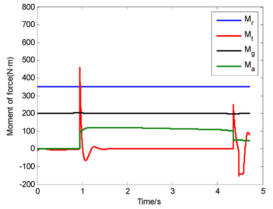
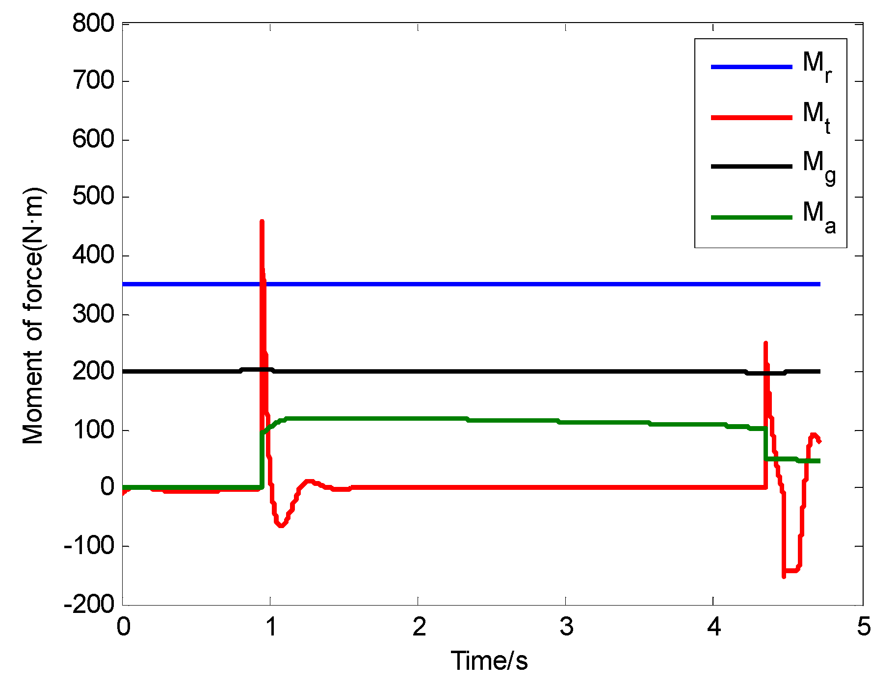
Each comparative moment of the force of the launch bar is shown in Figure 8 under the following conditions: mass of the launch bar = 40 kg; restoring moment of the launch bar = 350 N·m; proportionality factor of the launch bar = 40%.
Figure 8.
The comparison chart of moments.
We assumed that the restoring moment was a constant in this article. At the moment of the launch bar automatically disengaging from the shuttle at the end of the power stroke, only the restoring moment played a positive role when the launch bar was affected by four moments of force. In the three negative moments, the longitudinal moment of the force of inertia due to the acceleration of the pivot point worked less, whereas the moment of gravity of the launch bar had a large contribution and the moment of the force of inertia due to the nose landing gear’s sudden extension had a large contribution.
The moment of gravity of the launch bar changed less during the process of the free deck run. We can know that the moment of gravity of the launch bar changes with the change in angle between the launch bar and the nose gear according to the equation of the moment of gravity of the launch bar. The moment of gravity of the launch bar changed less because the angle between the launch bar and the nose gear changed less.
In the three negative moments, the longitudinal moment of the force of inertia due to the acceleration of the pivot point worked less. This phenomenon occurred because the longitudinal acceleration of the aircraft was smaller than the acceleration due to gravity and the acceleration of the elastic support mass.
The moment of the force of inertia due to the nose landing gear’s sudden extension changed greatly during the process of the free deck run. Furthermore, the first half of the moment of the force of inertia due to the nose landing gear’s sudden extension played a negative role, and the second half of it played a positive role. The moment of the force of inertia also changed greatly upon the sudden discharge of the holdback load in Figure 8. We should pay attention to the nose landing gear’s sudden extension and the sudden discharge of the holdback load during the process of landing gear design, so as to control launching safety.
In order to avoid the launch bar striking the deck surface, the restoring moment must overcome the total negative moments upon the launch bar automatically disengaging from the shuttle at the end of the power stroke.
4. Conclusions
There is no literature on the characteristics of launch bar dynamics after the launch bar automatically disengages from the shuttle at the end of the power stroke. This paper addressed the problem of the dynamics of the launch bar after the launch bar pops out of the shuttle. In this paper, several points were summarized as follows:
- A complete mathematical model of catapult launch used to characterize the dynamics of the launch bar was established. Several experimental data from previous research were used to verify the proposed model. The mathematical model of catapult launch including the launch bar can be used to predict the dynamic behavior of the launch bar in order to avoid the launch bar striking the flight deck.
- The changes in launch bar mass, launch bar restoring moment, and launch bar proportionality factor had no effect on the height from the pivot point to the deck. We can reduce the risk of collision between the launch bar and the deck by reducing the mass of the launch bar, increasing the restoring moment, and shifting the cg position of the launch bar.
- Under the working conditions of this article, we increased the center of gravity position of the launch bar to control the sink of the launch bar end, which had the most obvious effect, and we reduced the mass of the launch bar, which had the least effect when controlling the sink of the launch bar end. Furthermore, reducing the mass of the launch bar can also greatly reduce the risk of collision between the launch bar and the deck. In order to avoid the risk of collision between the launch bar and the deck after the launch bar automatically disengages from the shuttle at the end of the power stroke, the restoring moment of the launch bar must overcome the sum of the other moments. It is worth noting that the degree of influence of these factors on the results of the final values of the launch bar end may change if the working conditions change.
- The moment of the force of inertia due to the nose landing gear’s sudden extension changed greatly during the process of the free deck run. Furthermore, the first half of the moment of the force of inertia due to the nose landing gear’s sudden extension played a negative role, and the second half of it played a positive role. The moment of the force of inertia also changed greatly following the sudden discharge of the holdback load. In order to improve launching safety, we should pay attention to the nose landing gear’s sudden extension and the sudden discharge of the holdback load during the process of landing gear design.
- Selecting the optimal parameters for the launch bar is an important task, so as to control launching safety. The study results can give a theoretical reference for designing and testing the launch bars of carrier-based aircraft. It can also give a theoretical reference for designing and testing the launch bar’s driving mechanisms.
Author Contributions
Software, P.L.; writing—original draft, Q.Z. and P.L.; writing—review and editing, Q.Z., P.L., Z.Y., X.J., Y.H., and L.W.
Funding
This research was funded by the International Science & Technology Cooperation Program of China (2013DFR10030). This research was funded by the National Natural Science Foundation of China (61603110, 61803116, U1530119). This research was funded by the fundamental research funds for the central universities (HEUCFM170401, 3072019CFJ0405).
Conflicts of Interest
The authors declare no conflict of interest.
References
- Naval Air Engineering Center. Mil-Std-2066(AS) Military Standard Catapulting and Arresting Gear Forcing Functions for Aircraft Structural Design; Department of the Navy Air Systems Command: Patuxent, MD, USA, 1981. [Google Scholar]
- Fang, X.; Nie, H.; Zhang, Z. Dynamic response analysis on carrier-based UAV considering catapult shuttle mass. Acta Aeronaut. Astronaut. Sin. 2018, 39, 200–208. [Google Scholar]
- Zhu, Q.; Lu, P.; Yang, Z. Simulation research on deadload steam catapult systems. J. Harbin Eng. Univ. 2018, 39, 1979–1986. [Google Scholar]
- Slavin, F.J. Aircraft steam catapult. Mech. Eng. 1969, 91, 42–46. [Google Scholar]
- Shi, Y.; Shi, T.; Ma, W.; Gao, C. Design and simulation of inner and outer cylinder-type steam catapult. Adv. Mech. Eng. 2018, 10, 1–7. [Google Scholar] [CrossRef] [Scilit]
- Sun, B.Z.; Guo, J.M.; Lei, Y.; Yang, L.B.; Li, Y.J.; Zhang, G.L. Simulation and verification of a non-equilibrium thermodynamic model for a steam catapult’s steam accumulator. Int. J. Heat Mass Transf. 2015, 85, 88–97. [Google Scholar] [CrossRef] [Scilit]
- Naval Air Engineering Center. Mil-L-22589d(AS) Launching System, Nose Gear Type, Aircraft; Navy Air Engineering Center: Lakehurst, NJ, USA, 1991. [Google Scholar]
- Small, D.B. Full scale tests of nose tow catapulting. In Proceedings of the 1st AIAA Annual Meeting, Washington, DC, USA, 29 June–2 July 1964. [Google Scholar]
- Yu, H.; Nie, H. Launch bar load analysis of carrier-based aircraft during off-center catapult launch. Acta Aeronaut. Astronaut. Sin. 2010, 31, 1953–1959. [Google Scholar]
- Huang, L. Research on Optimization Design Technology of Ejection Mechanism of a Carrier-Based Aircraft Nose Landing Gear. Master’s Thesis, Nanjing University of Aeronautics and Astronautics, Nanjing, China, 2018. (In Chinese) [Google Scholar]
- Dennis, G.B.; Sidney, W.W. Aircraft and Devices for Launching Same. U.S. Patent 3,178,132, 13 April 1965. [Google Scholar]
- Boody, F.J. Aircraft Launching Mechanism. U.S. Patent 3,370,811, 27 February 1968. [Google Scholar]
- Smith, H.R. Launch Bar Installation. U.S. Patent 3,647,164, 7 March 1972. [Google Scholar]
- Derrien, M.; Ducos, D.; Engerand, J.L. Mechanism for Controlling a Catapult Bar. U.S. Patent 4,907,761, 13 March 1990. [Google Scholar]
- Wong, A.J. Nose Landing Gear Assembly for a Catapult Launched Airplane. U.S. Patent 5,732,906, 31 March 1998. [Google Scholar]
- Lucas, C.B. Catapult Criteria for a Carrier—Based Airplane; AD702814; Defense Technical Information Center: Fort Belvoir, WV, USA, 1968. [Google Scholar]
- Yu, H.; Nie, H. Dynamics Analysis of Carrier-Based Aircraft with Off-Center Catapult Launch. J. Nanjing Univ. Aeronaut. Astronaut. 2010, 42, 537–542. [Google Scholar]
- Yu, H.; Nie, H. Effects of off-center location on aircraft attitude during catapult launch. J. Beijing Univ. Aeronaut. Astronaut. 2011, 37, 10–14. [Google Scholar]
- Zhu, Q.; Liu, H.; Li, X. Research on carrier-based aircraft catapult launching in the case of different eccentricity. Flight Dyn. 2016, 34, 10–14. [Google Scholar]
- Lin, J.; Zhang, Y.; Le, T.; Wang, L. Effects of asymmetric factors to carrier-based aircraft catapult launch. J. Beijing Univ. Aeronaut. Astronaut. 2018, 44, 363–374. [Google Scholar]
- Wallace, M.M. F/A-18E/F Catapult Minimum End Airspeed Testing. Master’s Thesis, University of Tennessee, Knoxville, TN, USA, 2002. [Google Scholar]
- Loftus, J.; Piekarski, B. Carrier suitability tests of the rafale airplane in United States. In Proceedings of the Biennial Flight Test Conference, Hilton Head, SC, USA, 20–23 June 1994. [Google Scholar]
- Guo, Y.; Li, H.; Shen, G.; Yang, T. Modeling and analyze of the environmental factors of carrier-based aircraft catapult launch in complex environment. J. Beijing Univ. Aeronaut. Astronaut. 2011, 37, 877–881. [Google Scholar]
- Cai, L.; Jiang, J.; Wang, X.; Pan, T. Effects of deck motion on carrier-based aircraft’s catapult launching performance. Flight Dyn. 2014, 32, 105–109. [Google Scholar]
- Feng, Y.; Chen, B.; Zhang, B.; Xia, B.; Li, R. Influence factor analysis on the catapult launch of the carrier-based aircraft by the aircraft carrier’s vertical toss. Flight Dyn. 2019, 37, 22–27. [Google Scholar]
- Yan, C.; Feng, J. Automatic control flight for a carrier-based airplane in climb phase during catapult launch. J. Nanjing Univ. Aeronaut. Astronaut. 1995, 27, 431–438. [Google Scholar]
- Zhu, Y.; Jiang, J.; Zhen, Z.; Wang, X.; Jiao, X. Control law for climbing stage of carrier-based aircraft in catapult-assisted take-off. Electron. Opt. Control 2012, 19, 13–16. [Google Scholar]
- Lin, J.; Wang, L.; Yue, T. Lateral-directional flight control for single engine failure in catapult launch. In Proceedings of the 36th Chinese Control Conference, Dalian, China, 26–28 July 2017. [Google Scholar]
- Wu, W.; Song, L.; Zhang, Y.; Wang, J.; Gao, L. Analysis of factors affecting catapult take-off of carrier aircraft and design of lateral control law. J. Beijing Univ. Aeronaut. Astronaut. 2019, 45, 662–671. [Google Scholar]
- Shen, Q.; Huang, Z. Sensitivity analysis of fast-extension performance of carrier based aircraft landing gear to varying parameters. Acta Aeronaut. Astronaut. Sin. 2010, 31, 532–537. [Google Scholar]
- Wei, X.; Liu, C.; Nie, H.; Zhang, M.; Yin, Q. Dynamics and test method of carrier-based aircraft nose landing gear sudden extension. Acta Aeronaut. Astronaut. Sin. 2013, 34, 1363–1369. [Google Scholar]
- Dou, Q.; Chen, Y.; Ma, X.; Mu, R. Experimental study on the sudden-extension performance of carrier-based aircraft landing gear. J. Vib. Eng. 2018, 31, 102–109. [Google Scholar]
- Liu, X.; Xu, D.; Wang, L. Match characteristics of aircraft-carrier parameters during catapult takeoff of carrier-based aircraft. Acta Aeronaut. Astronaut. Sin. 2010, 31, 102–108. [Google Scholar]
- Wilson, T. F-35 carrier suitability testing. In Proceedings of the 2018 Aviation Technology, Integration, and Operations Conference, Atlanta, GA, USA, 25–29 June 2018. [Google Scholar]
- Zhu, Q.; Lu, P.; Yang, Z.; Ji, X.; Han, Y. Multi-Parameter Optimization for the Wet Steam Accumulator of a Steam-Powered Catapult. Energies 2019, 12, 234. [Google Scholar] [CrossRef] [Scilit]
- Zhu, Q.; Li, X.; Yu, Y. Analysis of dynamic characteristics of catapult launch for a carrier-based aircraft with sudden load discharge. J. Harbin Eng. Univ. 2012, 33, 1150–1157. [Google Scholar]
- Zhu, Q.; Lu, P.; Yang, Z.; Cui, Y. Model research of steam catapult launch process for carrier-based aircraft. In Proceedings of the 37th Chinese Control Conference, Wuhan, China, 25–27 July 2018. [Google Scholar]
- U.S. Naval Air Engineering Center. Evaluation of Advanced Method for Steam Catapult Performance Prediction with Shipboard Test Data; AD742804; U.S. Naval Air Engineering Center: Lakehurst, NJ, USA, 1972. [Google Scholar]
- MIL-A-8863C. Airplane Strength and Rigidity Ground Loads for Navy Acquired Airplanes; United States Coast Guard: Washington, DC, USA, 1993. [Google Scholar]

© 2019 by the authors. Licensee MDPI, Basel, Switzerland. This article is an open access article distributed under the terms and conditions of the Creative Commons Attribution (CC BY) license (http://creativecommons.org/licenses/by/4.0/).