


Featured Application
Flexible heat exchangers for wearable devices.
Abstract
Flexible heat exchangers with intricate three-dimensional (3D) geometries exhibit superior mechanical and thermal performance compared with traditional two-dimensional (2D) designs. Their ability to offer greater design freedom and unique functionalities makes them particularly attractive for wearable medical devices. This study investigates flexible heat exchanger technologies in three main directions: (i) miniaturisation, (ii) integration of physical and mathematical models, and (iii) enhanced adaptability through heterogeneous design integration. Through a combination of literature review, mathematical modelling, and experimental analysis, the thermal efficiency of several configurations is compared, including basic thermoplastic polyurethane (TPU) tubes and 3D bio-inspired TPU tubes with aluminium-finned structures. The findings establish a foundation for the development of next-generation flexible wearable medical cooling devices with improved thermal management capabilities and practical applicability in industrial design. Furthermore, the outcomes of this research will directly support the development of improved wearable cooling devices within a UK-based medical device SME, Paxman Scalp Coolers, facilitating the translation of advanced heat exchanger designs into clinically relevant and commercially viable solutions.
1. Introduction
The rapid advancement of flexible wearable materials and devices is driving the development of next-generation technologies across healthcare, consumer electronics, and industrial sectors [1]. Wearable systems including smart garments, medical monitors, and health sensors can track physiological and biomechanical data in real time or deliver targeted thermal or mechanical stimuli [2]. However, designing such systems remains a challenging task. Multiple electronic, mechanical, and thermal functions must be integrated into platforms that are soft, lightweight, and conformable. To address these challenges, fabrication techniques such as laser processing, transfer printing, and advanced additive manufacturing are increasingly employed.
Efficient thermal management is essential for ensuring the reliable operation of advanced wearable devices, which are increasingly miniaturised, integrated, and ultrathin. Incorporating thermal regulation into such systems is complex because thermal, mechanical, ergonomic, and application-specific constraints must all be balanced. Conventional rigid materials with high thermal conductivity are often unsuitable because they lack the flexibility required in wearable technologies [3,4].
Among these challenges, heat dissipation remains one of the most critical issues in wearable heat exchanger (HE) design. Performance depends strongly on the device’s location on the body, the thermal loads involved, and the nature of skin contact. HEs are key components that facilitate heat transfer, particularly between two fluids, enabling a process fluid to be heated or cooled to a desired temperature. Heat transfer typically occurs through a combination of conduction, convection, and radiation. For example, when hot and cold fluids flow on either side of a partition wall, both conduction and convection occur on both sides of the wall. In many applications, this heat exchange takes place without a phase change.
Enhancement of heat transfer (HT) can be achieved using either active or passive techniques [5,6]. Active methods rely on external power input, whereas passive methods improve HT without additional energy, often using extended surfaces, turbulence promoters, or modified internal geometries. Internal surface enhancements are particularly effective in improving HE performance [7,8]. One such technique involves incorporating finned, tentacle-like structures inside tubes to disturb the flow, increase the surface area, and reduce thermal resistance. Inspired by biological systems such as respiratory cilia and intestinal microvilli, researchers have explored synthetic analogues to improve heat transfer [9,10]. Passive techniques such as vortex generators, surface roughness modifications, and surface area augmentation have proven effective in enhancing HE performance as discussed below. These approaches typically involve:
- Increased surface area: Tentacle-like fins provide more area for convective HT.
- Turbulence induction: Fins disrupt laminar boundary layers, increasing convective HT coefficients.
- Flow mixing and recirculation: Fins promote bulk fluid interaction with the tube walls.
- Enhanced thermal pathways: Fins act as thermal bridges between the fluid and the tube wall.
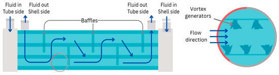
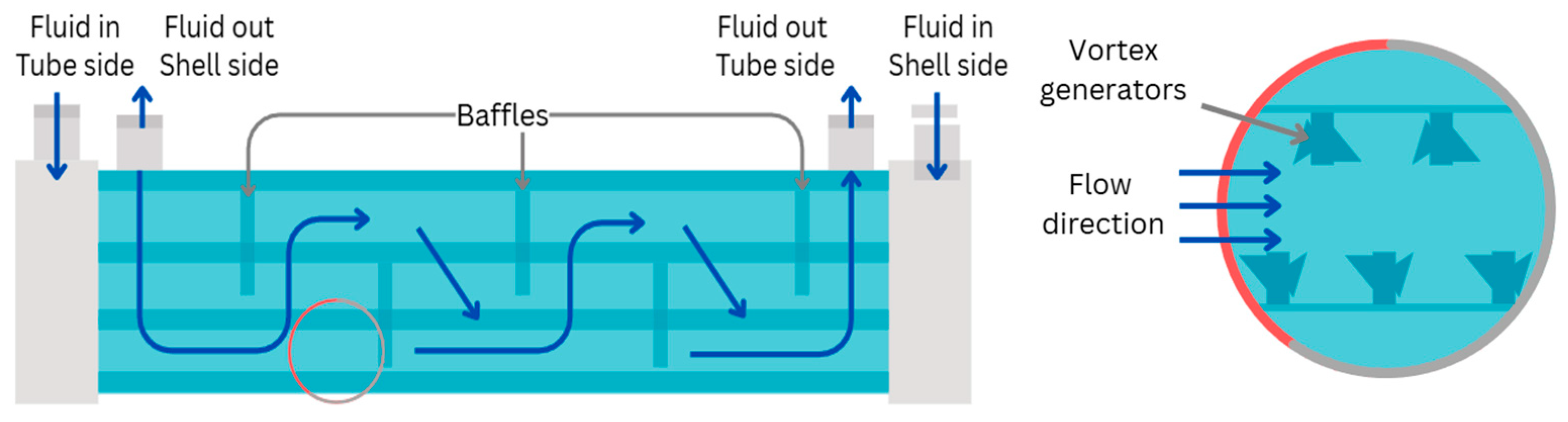
The use of vortex generators such as twisted tapes, ring-shaped inserts, baffles, turbulators, winglets, pins, and fins are established strategies for enhancing HE performance (Figure 1).
Figure 1.
Representative vortex generators and turbulator-type internal flow enhancers.
This project followed a case study with a global medical company, Paxman, a global medical company specialising in wearable heat exchangers (HE) for the prevention of Chemotherapy-Induced Alopecia (CIA) and CIPN (chemotherapy-induced peripheral neuropathy). For CIA, close fit and fluid performance are essential characteristics used to ensure optimal heat exchange between the scalp and the scalp cooling cap, enabling efficient heat extraction to induce vasoconstriction, a key mechanism in preventing chemotherapy drugs from attacking hair follicles [11].
This collaboration has sought to improve heat exchange efficiency through the integration of internal mechanisms within the cooling cap, enabled by additive manufacturing approaches. Furthermore, the outcomes of this project will contribute to improving thermal efficiency and fluid performance in ongoing CIPN device development at Paxman, supporting enhanced cooling performance for extremity-based therapies.
Efficient thermal management remains a critical challenge in the development of wearable electronics and compact heat exchange systems, where constraints on flexibility, size, and power limit the use of conventional cooling strategies. Recent work by Liu et al. highlights that wearable systems increasingly require integrated thermal regulation solutions that balance heat dissipation with mechanical compliance [12]. Similarly, Yun et al. provide a comprehensive overview of recent progress in flexible and wearable thermal management, emphasising emerging strategies such as soft thermal interface materials, stretchable heat spreaders, and embedded microfluidic cooling [13]. Both studies underline the need for solutions that simultaneously address thermal performance, flexibility, and user comfort. At the microscale, heat transfer enhancement techniques have focused heavily on geometric modification of flow channels. Zhou et al. demonstrated through numerical modelling that the inclusion of micro pin fins significantly improves convective heat transfer by increasing surface area and promoting local turbulence [14]. Their results show notable enhancement in Nusselt number with only moderate increases in pressure drop, indicating a favourable thermal–hydraulic trade-off. Beyond static geometries, dynamic flow manipulation has also been explored. Persoons et al. investigated pulsating flow in mini-channel heat sinks and reported that flow oscillations can enhance heat transfer performance by periodically disrupting thermal boundary layers [15]. This suggests that unsteady flow conditions may offer an alternative or complementary strategy to purely geometric enhancements.
Biomimetic approaches have gained increasing attention as a means of achieving high-performance heat transfer. For instance, Wang et al. developed a biomimetic microchannel heat sink inspired by natural flow structures, demonstrating improved thermal performance compared to conventional designs [16]. Yang et al. multi-scale review showed how lung-like and leaf-vein structures promote uniform flow distribution and enhanced mixing, albeit often with an associated pressure drop penalty [10]. Similarly, vascular-inspired heat exchangers fabricated using additive manufacturing have shown increased surface area density and improved convective performance due to enhanced flow mixing within branched channels [17]. Hwang et al.’s review on nature-inspired HE emphasised the role of fractal geometries and hierarchical patterns in maximising HT area while maintaining compactness, drawing parallels with natural phenomena such as snowflakes and plant structures [18]. Such bio-inspired designs typically aim to replicate natural transport phenomena, including branching networks and surface textures, to optimise fluid mixing and heat exchange. Similarly, vortex generation techniques have been widely studied for their ability to enhance convective transport. Luo et al. provides a comprehensive review of longitudinal vortex generators, showing that these structures can significantly improve heat transfer by inducing secondary flows and increasing fluid mixing, although often at the expense of higher-pressure losses [19]. From an application perspective, the integration of thermal management systems into wearable platforms has also been explored. Dabrowska et al. investigated active cooling garments integrated within IoT-enabled architectures, demonstrating that liquid cooling systems can effectively regulate body temperature in demanding environments [20]. Their work highlights the importance of system-level integration, including sensors, control systems, and user-specific adaptability. Overall, the literature indicates that effective thermal management in wearable and compact systems relies on a combination of strategies, including advanced flexible materials, microstructural enhancement (e.g., fins and vortex generators), dynamic flow control, biomimetic design, and system-level integration. Future developments are likely to focus on hybrid approaches that combine these methods while maintaining low power consumption, flexibility, and user comfort.
The study offers insights into next-generation flexible devices with improved thermal management, particularly for wearable medical applications. Additionally, the research investigates design optimisation of tubular heat exchangers, focusing on enhancing their efficiency and integration into wearable systems. The development process involves careful material selection and fabrication, integrating flexible tubes into breathable textiles to ensure comfort and usability. To ensure durability and performance, tubes with fin-like structures are sealed using lamination, providing a robust and reliable thermal management solution.
2. Flexible Heat Exchanger for Wearable Devices
Wearable devices with integrated heat exchangers have gained significant attention due to their potential to provide personalised thermal management in medical, sports, and industrial applications. Tubular heat exchangers are particularly attractive in this context because of their flexibility, ease of integration, and potential for customisation. These systems typically consist of small, flexible tubes through which a heat transfer fluid (e.g., water or a glycol solution) circulates. The main function is to transfer heat between the body and the fluid (or, in some designs, between the body and ambient air). Such systems are widely adopted in wearable designs because they can conform to the contours of the human body, allowing close skin contact and efficient heat exchange [20]. The flexibility of the tubes enables seamless integration into garments and accessories such as jackets, vests, and wristbands.
A key consideration in the development of tubular heat exchangers for wearable devices is the selection of appropriate materials. Thermoplastic polyurethane (TPU) and silicone are the most used materials due to their excellent flexibility, durability, and chemical resistance. These properties are crucial for ensuring longevity, comfort, and safety in wearable applications. Their ability to withstand mechanical deformation under varying environmental conditions further supports their use in such systems. However, their relatively low thermal conductivity can limit heat transfer efficiency. The effectiveness of tubular heat exchangers in wearable designs largely depends on their ability to maintain efficient heat transfer while remaining comfortable and unobtrusive. Optimising the fluid flow rate, tube dimensions, and overall geometry can significantly improve thermal performance.
Recent research has focused on improving thermal performance by integrating high-conductivity materials such as graphene and aerogels, which enhance HT while maintaining the lightweight and flexible characteristics required for wearables. In parallel, 3D printing technologies have enabled the creation of intricate microchannel designs within tubes, providing greater control over fluid flow and improved heat dissipation [21].
2.1. Performance and Efficiency in Wearable Heat Exchangers
Studies have explored integrating phase-change materials (PCMs) into tubular systems to provide passive thermal regulation by absorbing and releasing heat at specific temperatures [22]. Other work has examined the influence of low thermal conductivity in filled polymers on the overall thermal performance of compact finned-tube heat exchangers using computational fluid dynamics (CFD) simulations [23].
However, challenges remain in achieving an optimal balance between heat transfer efficiency, energy consumption, and wearer comfort. Wearable heat exchangers must maintain acceptable weight and fit while avoiding local overheating or discomfort. This balance is particularly important in applications involving physical activity or fluctuating environmental conditions.
2.2. Applications of Tubular Heat Exchangers in Wearable Devices
Wearable heat exchangers have been applied across a wide range of fields. In medical applications, they are used to regulate body temperature in patients with hyperthermia or hypothermia and to improve circulation or manage local thermal therapies. For athletes, tubular heat exchangers can provide cooling or heating, improving performance by mitigating heat stress and fatigue.
In industrial contexts, wearable heat exchangers protect workers in extreme temperatures, thereby improving safety and productivity. They also have potential in military and first-responder applications, where reliable thermal management is vital. In all these applications, successful integration of heat exchangers into garments without compromising comfort is critical. The flexibility of tubular heat exchangers allows designs that conform to the body and can be worn continuously, enabling efficient yet discreet thermal management. For more efficient wearable cooling, contact is important for providing the most optimal parameters for energy extraction. Gaps between the body and the heat exchanger can cause insulation pockets, and according to Fourier’s law, the thinner the interface (or distance between the hot and cold sides) the more energy can be extracted more rapidly. Tolerability is also crucial for wearable design, if the device cannot be tolerated, then the efficacy is irrelevant.
3. Design Challenges: Bioinspired Inspiration for 3D Heat Exchanger and Thermal System Enhancements
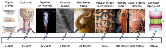
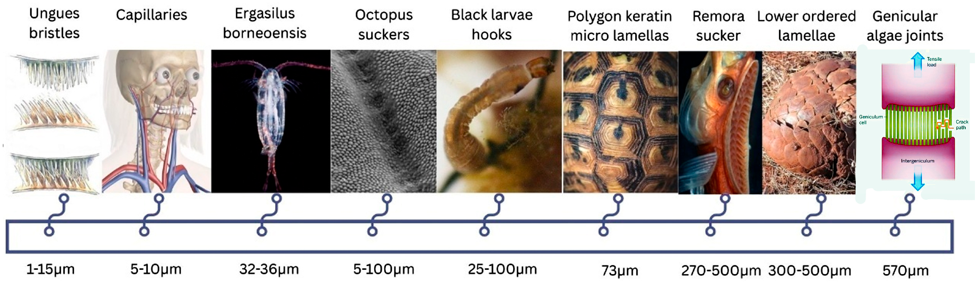
Nature offers valuable design insights through optimised structures and functions that have evolved to overcome thermal and mechanical limitations (Figure 2). Bio-inspired strategies have led to innovative approaches in 3D heat exchanger design, enhancing thermal conductivity, adaptability, and overall system performance [24]. The use of tubular heat exchangers in wearable devices shows strong potential for personalised thermal management. However, several challenges persist. The primary limitation lies in the trade-off between heat transfer efficiency and material flexibility. TPU and silicone tubes, while cost-effective and durable, have lower thermal conductivity than metals and may not provide sufficient heat dissipation in high-demand environments. There is a clear knowledge gap in developing advanced materials such as composite polymers or metal–polymer hybrids that combine flexibility with improved thermal conductivity.
Figure 2.
Visual representation of biomimicry structures.
While TPU offers an excellent balance of flexibility and durability, ongoing research is aimed at addressing its limitations in thermal efficiency and at integrating advanced manufacturing techniques to improve overall performance. As these technologies evolve, wearable heat exchangers are expected to play an increasingly important role in improving comfort, performance, and safety in both medical and industrial applications, and are represented in Figure 3.
Figure 3.
Internal Structures for turbulence generation.
Although 3D printing with hard plastics or metals for heat exchangers has been extensively studied and shown to enhance thermal performance, the application of additive manufacturing to heat exchangers made from soft materials such as silicone or TPU still faces major limitations. These include low print resolution, deformation during printing, and difficulties in generating water-tight structures and removing support structures without damaging the material. Post-processing can be particularly demanding due to the risk of tearing or distortion, while slow print speeds and high production costs further limit scalability. In addition, inconsistencies in mechanical and thermal properties raise concerns regarding reliability. In medical applications, these challenges are compounded by stringent regulatory requirements, where reproducibility, biocompatibility, and traceability are essential yet more difficult to guarantee with soft, additively manufactured components. This research highlights core bio-inspired concepts, fabrication strategies, and structure–function relationships relevant to 3D thermal systems. It also outlines key challenges, emerging solutions, and future research opportunities for next-generation heat exchange technologies.
3.1. The Need for Wearable Heat Exchangers
Personal cooling and heating systems play a vital role in maintaining comfort under extreme temperature conditions by dissipating excess heat or providing necessary warmth. These systems enhance performance for athletes, military personnel, and industrial workers by preventing overheating and fatigue. In medical applications, they assist in managing conditions such as hyperthermia and impaired thermoregulation or circulation. They can also contribute to energy efficiency by reducing reliance on building-level heating or cooling systems, supporting more sustainable temperature control. In extreme environments like space, firefighting, and hazardous industrial settings wearable heat exchangers provide precise thermal management essential for safety and mission success.
Wearable heat exchangers are compact, lightweight thermal management devices integrated into clothing or accessories to regulate body temperature. They are designed using advanced materials and engineering techniques to ensure that they are lightweight, efficient, and comfortable. The manufacturing process typically involves several key components and technologies, including:
- Heat Transfer Medium: circulated fluid such as water, glycol, depending on the system design.
- Microchannels or Tubing: thin, flexible tubes made of silicone, polymers, or metals that facilitate fluid circulation for heating or cooling.
- Thermoelectric Modules (Peltier Effect): components that provide active heating or cooling by transferring heat using an electric current.
- Phase-Change Materials (PCMs): encapsulate materials that absorb and release heat at specific temperatures, enabling passive thermal control.
- Sensors and Electronics: temperature and humidity sensors that monitor body conditions and regulate heat exchange in real time.
- Power Source: batteries or energy-harvesting technologies, such as thermoelectric generators, that supply power for active systems.
3.2. Developments, Requirements and Limitations
The Paxman Scalp Cooling CIA and CIPN devices utilise a liquid-based thermal management system in which flexible bladders containing integrated cooling channels are wrapped around the hands and feet or cap. These bladders are connected via a closed-loop circuit to an external refrigeration unit, where coolant is actively cooled to controlled temperatures (typically in the range of ~−5 to 15 °C, depending on therapeutic protocol) and continuously circulated through the channels. This ensures uniform heat extraction, reducing local tissue temperature and thereby limiting neurotoxic drug uptake and metabolic activity associated with nerve damage.
The configuration of the bladder used for cooling the hands and feet plays a critical role in overall performance; specifically, reducing its volume and thickness can improve thermal efficiency by lowering thermal resistance and enhancing contact between the cooling surface and the skin. Smaller, well-distributed channel geometries promote more effective convective heat transfer and temperature uniformity. Importantly, if engineered with compliant, soft materials and optimised channel layouts, these smaller bladders can maintain or even improve wearer comfort by enhancing flexibility, reducing bulk, and enabling better anatomical conformity, thereby achieving a balance between efficient cooling and patient tolerability [25]. Tubes are generally manufactured in TPU or silicone material for wearable heat exchanger applications due to their flexibility, durability and light weight, their relatively low thermal conductivity and limited tolerance to high pressures and temperatures constrain heat transfer efficiency. TPU can also absorb moisture, which may affect long-term performance. Alternatives to these materials include advanced polymers such as polyether ether ketone (PEEK) and graphene-based composites, which offer higher thermal conductivity and greater pressure resistance. 3D-printed structures with bio-inspired geometries have the potential to enhance heat transfer efficiency. These advanced materials may help overcome some of the limitations associated with silicone and TPU, thereby improving the performance of wearable thermal management systems in low volume manufacturing not for an SME to commercially mass manufacture. Despite these promising alternatives, TPU/Silicone remain the predominant materials in wearable design due to their commercial availability, cost-effectiveness, recyclability, scalability for high-volume production, and lower susceptibility to leakage and air entrapment.
4. Mathematical Modelling
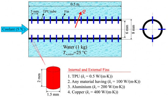
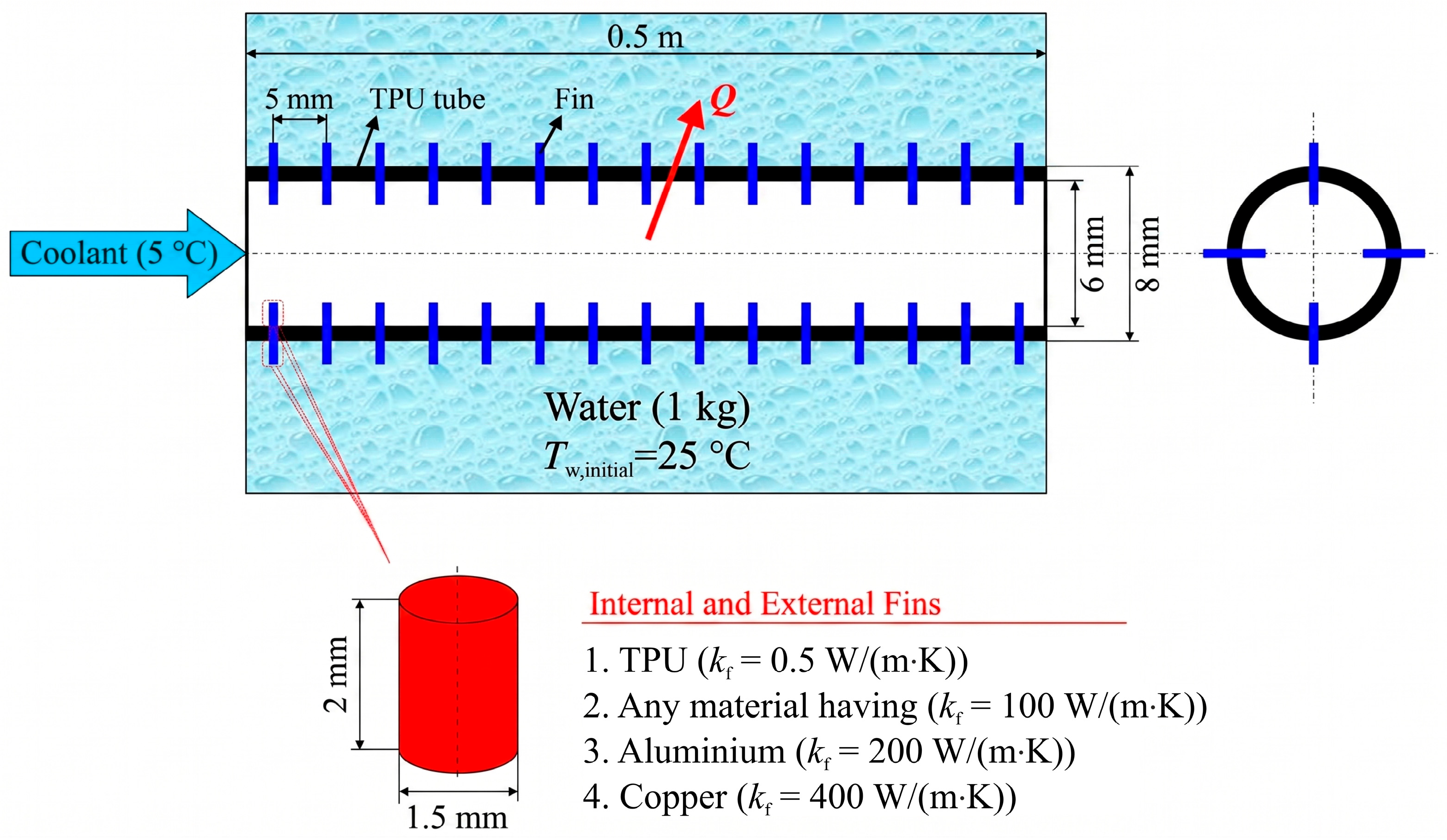
In this study, a transient thermal model was developed to evaluate the cooling performance of a flexible TPU tube equipped with circular pin fins. The system geometry is illustrated in Figure 4. A 0.5 m-long tube with inner diameter di = 6 mm and outer diameter do = 8 mm is horizontally placed inside a thermally insulated shell filled with quiescent water initially at Tw,initial = 25 °C. Coolant water at a constant inlet temperature of Tc,in = 5 °C flows inside the tube. Heat is transferred from the shell-side water to the tube outer wall by natural convection, and from the tube inner wall to the coolant via forced convection. The low thermal conductivity of the tube material (kt = 0.5 W/m·K) represents a thermally resistive wall, offering an opportunity to assess the enhancement provided by the addition of fins with varying thermal conductivity.
Figure 4.
Schematic representation of the investigated heat transfer configuration.
Assumptions, Geometrical Parameters and Thermal Modelling
To increase the effective heat transfer area and induce thermal interaction, circular pin fins of diameter 1.5 mm and height of 2 mm were symmetrically mounted on both inner and outer surfaces of the tube. Four fins were arranged per section with a 5 mm longitudinal spacing. The study investigates five distinct configurations: (i) no fins (baseline), and (ii–v) fins made of materials with different thermal conductivities: TPU (kf = 0.5 W/m·K), an idealized high-conductivity case (kf = 100 W/(m·K)), aluminium (kf = 200 W/(m·K)), and copper (kf = 400 W/(m·K)). These variations allow for a comparative analysis of the impact of fin thermal conductivity on the overall cooling efficiency and fin efficiency. The schematic (Figure 4) shows the direction of fluid flow, representative pin fins, and associated heat fluxes. The geometric and thermal parameters are summarised in Table 1.
Table 1.
Summary of geometrical and thermal parameters.
The thermophysical properties and model parameters used in this study are based on standard values and widely accepted correlations reported in the heat transfer literature [26]. Following this, the mathematical model incorporates some simplifying assumptions: quasi-steady, incompressible internal flow; axisymmetric and one-dimensional radial heat conduction in the tube wall; lumped thermal modelling of the water inside the shell; negligible axial conduction in fluids and the tube wall; and constant thermophysical properties.
The present model adopts a resistance-based lumped formulation combined with empirical correlations for convective heat transfer. This approach is widely used in preliminary heat exchanger design and enables capturing the dominant thermal transport mechanisms with reduced computational complexity. While the presence of internal fins alters the local flow structure, the use of baseline correlations with enhancement factors provides a first-order approximation of fin-induced mixing and thermal boundary layer disruption effects. Such an approach is particularly suitable for flexible and bio-inspired geometries, where fully resolved numerical simulations remain computationally demanding.
The governing equations and correlations used in this study are based on well-established formulations in heat transfer literature [27]. The transient heat transfer process is fundamentally governed by the Fourier–Kirchhoff equation:
In the present study, this general formulation is simplified into a resistance-based lumped model in order to capture the dominant heat transfer mechanisms with reduced computational complexity. Rather than directly solving the full governing equation, a reduced-order thermal resistance network is employed.
Accordingly, the heat transfer rate from the water inside the shell to the coolant flowing inside the tube can be calculated using a transient energy balance:
Here, U(t) is the overall heat transfer coefficient (W/(m2·K)), Atot is the total effective surface area including fins (m2), and ΔTlm is the logarithmic mean temperature difference at time t. The coolant inlet temperature is assumed constant based on controlled operating conditions and is incorporated in the calculation of the logarithmic mean temperature difference (ΔTlm). The coolant flow is modelled as internal forced convection with a constant inlet temperature boundary condition.
The overall heat transfer coefficient (U) is calculated by the resistance analogy:
The presence of fins increases the total heat transfer area. The total internal and external surface areas, including the contribution of circular pin fins, are given by:
Efficiency of the fins are calculated using the classical approximation:
where the parameters m and Lc are defined as:
Heat transfer coefficients (h) are derived from non-dimensional empirical Nusselt number (Nu) correlations available in the literature. Reynolds number based on the inner tube diameter was first calculated to determine the internal flow regime.
For turbulent flow inside the tube, assumed due to short entrance length, Dittus-Boelter correlation is employed:
For laminar flow, developing thermal boundary conditions are accounted for using the correlation by [28]:
Adding fins into the tube will not only increase the heat transfer surface area but also alter the flow domain that leads to enhanced heat transfer. Therefore, heat transfer coefficient was multiplied by an enhancement factor of 1.2 and 1.5 for the laminar and turbulent flow regimes, respectively. Adding fins into the tube will also enhance convective mixing and locally thin the thermal boundary layer. To incorporate this effect, enhancement factors of 1.2 (laminar) and 1.5 (turbulent) are applied to hi [29]. The enhancement factors applied to the internal heat transfer coefficient are not intended to represent universal correlations, but rather engineering approximations based on reported increases in convective heat transfer due to internal structures such as fins, inserts, and vortex generators. Previous studies have shown that such modifications can increase the Nusselt number by approximately 20–50% depending on geometry and flow regime. Accordingly, conservative enhancement factors of 1.2 (laminar) and 1.5 (turbulent) were selected to represent moderate augmentation effects.
Natural convection between the outer tube wall and the shell water is modelled via Rayleigh number-based empirical correlations. The outer heat transfer coefficient ho is calculated using Churchill and Chu (1975) correlation for horizontal cylinders [30]:
To complete the mathematical formulation, the model is solved subject to the following initial and boundary conditions. Initially, the tank water (Tw,initial) is assumed to have a uniform temperature. The coolant flow is defined by a constant inlet temperature boundary condition. Heat transfer inside the tube is modelled as internal forced convection, while the external surface is subjected to natural convection. These assumptions are consistent with simplified heat exchanger modelling approaches widely used in the literature [26].
The full transient model was implemented and solved using Engineering Equation Solver (EES) software. The simulation was run for a period of 5000 s with a 1 s time step. Flow-dependent convective coefficients and fin efficiencies were evaluated dynamically at each time step. The model was solved for cooling water flow rates ranging from 0.5 to 1.5 L/min, thus capturing both laminar and turbulent internal flow regimes. In the analyses, the thermal conductivity (kf) of the fin material was also varied and its effect on the cooling of the water was investigated. The results are presented and discussed in the following section.
5. Simulation Results and Discussion
This section presents the results of the transient thermal simulations and discusses the impact of coolant flow rate and fin thermal conductivity on system performance. The influence of fins is examined in terms of convective heat transfer coefficients, fin efficiency, thermal resistances, and water temperature evolution over the 5000 s cooling period. Although temperature evolution is presented as an overall performance indicator, the analysis is primarily based on fundamental heat transfer parameters such as convective heat transfer coefficients, thermal resistance components, and fin efficiency. These metrics allow the observed thermal behaviour to be interpreted in terms of underlying transport mechanisms.
5.1. Variation in Heat Transfer Coefficients
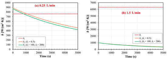
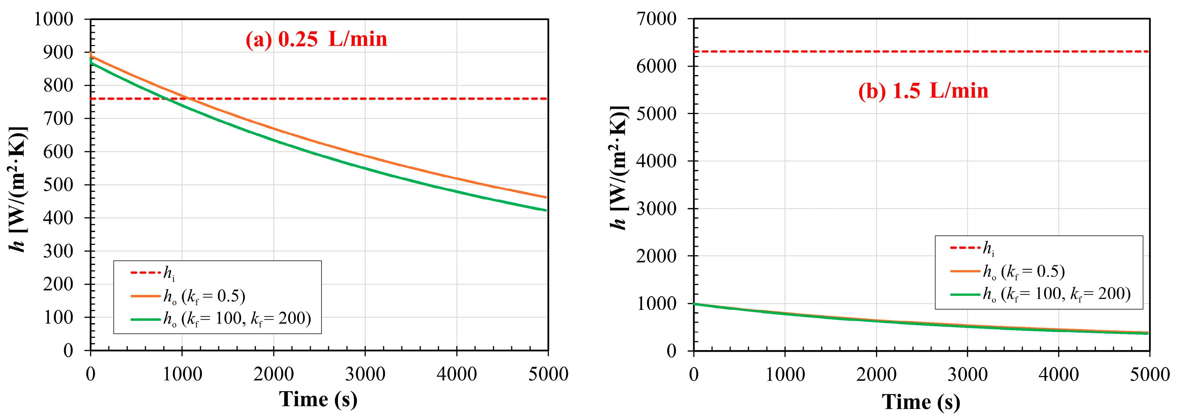
The time-dependent behaviour of the convective heat transfer coefficients inside the tube (hi) and on the shell side (ho) is illustrated in Figure 5 for two representative coolant flow rates: 0.25 L/min and 1.5 L/min, allowing a transport-based interpretation of the convective heat transfer mechanisms beyond temperature evolution. At the lower flow rate (Figure 5a), the internal flow remains laminar, and hi is nearly constant throughout the cooling period. Initially, ho is higher than hi due to the large temperature difference between the outer tube wall and the shell water. However, as the shell water temperature decreases and this difference narrows, the Rayleigh number, and hence ho gradually decreases. Eventually, hi surpasses ho in magnitude.
Figure 5.
Temporal variation in internal and external heat transfer coefficients at coolant flow rate of (a) 0.25 L/min and (b) 1.5 L/min.
At the higher flow rate (Figure 5b), the internal flow transitions to the turbulent regime, leading to a significant increase in hi. In this case, the internal heat transfer coefficient remains substantially larger than ho throughout the process, indicating that the thermal resistance is now dominated by the shell side.
Importantly, the thermal conductivity of the fin material (kf) has no noticeable influence on the internal heat transfer coefficient hi, as it is primarily governed by the flow rate and tube geometry. However, kf does affect ho, albeit indirectly. As kf increases, fins conduct heat more efficiently away from the outer surface, thereby reducing the outer wall temperature. This reduces the driving temperature difference for natural convection and consequently lowers the Rayleigh number and ho.
5.2. Fin Efficiency and Thermal Conductivity Influence
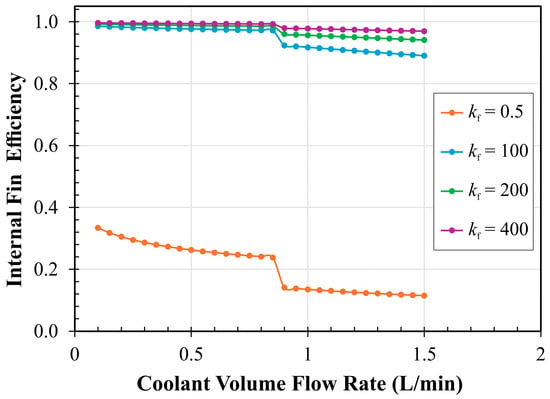
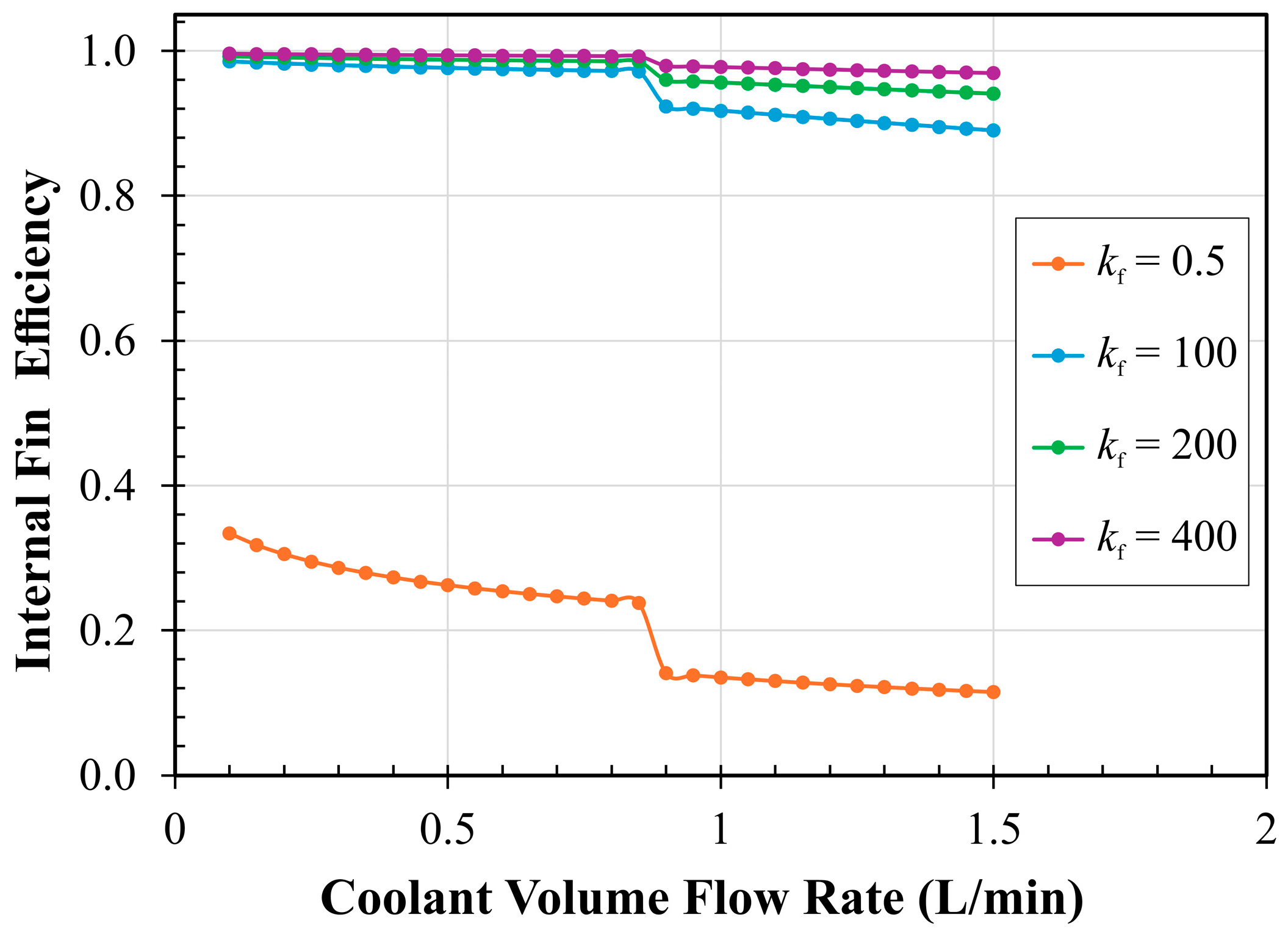
The efficiency of the fins, both on the inner and outer surfaces of the tube, is critically influenced by the thermal conductivity of the fin material (kf) and the local convective environment. Figure 6 illustrates the variation in internal fin efficiency as a function of coolant flow rate for different kf values. When kf is low (e.g., TPU with 0.5 W/(m·K)), the internal fin efficiency remains low across all flow rates due to the significant thermal resistance within the fin material itself. As kf increases to values of 100 W/(m·K) and above, the fin efficiency improves substantially, approaching near-unity levels. However, in turbulent flow conditions, this efficiency decreases slightly as the convective heat transfer coefficient hi increases, reducing the temperature gradient between the fin base and tip.
Figure 6.
Internal fin efficiency as a function of coolant flow rate for different fin materials.
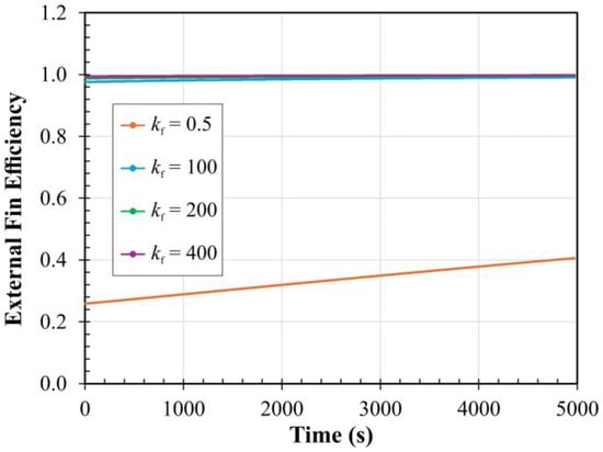
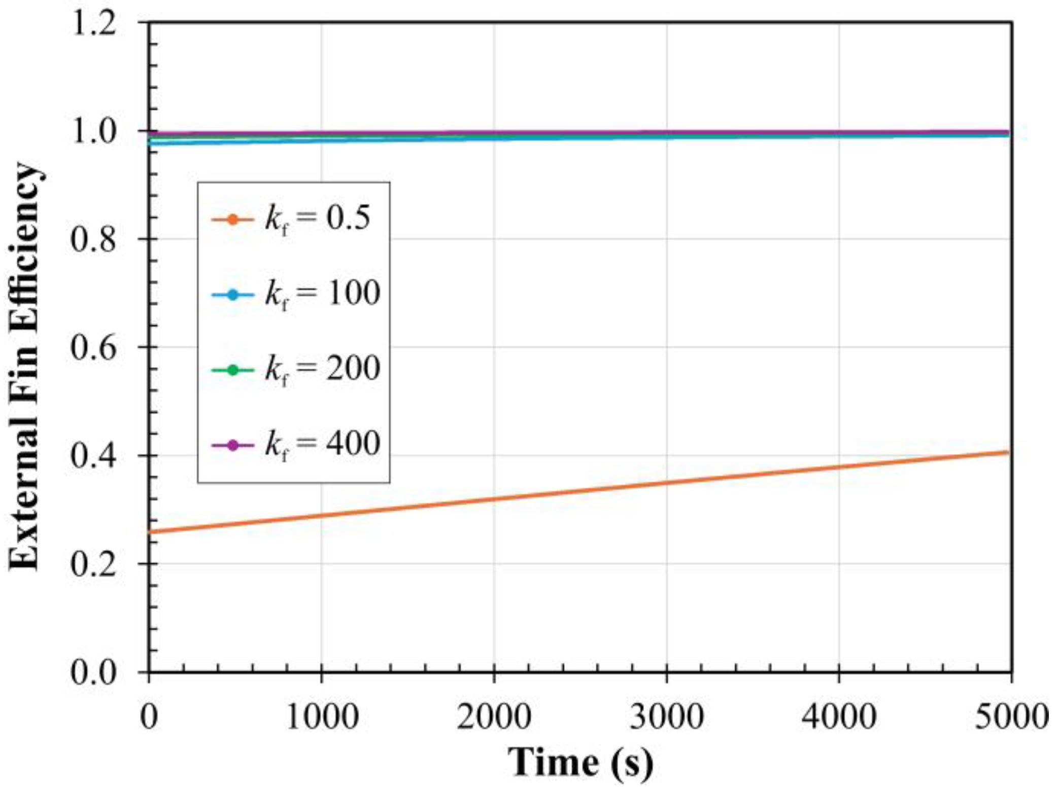
The external fin efficiency exhibits a different behaviour, as shown in Figure 7, which plots its time-dependent variation for a high coolant flow rate of 1.5 L/min. Unlike the internal case, the efficiency of external fins increases over time. This is due to the decreasing shell-side heat transfer coefficient ho, which increases the relative thermal resistance on the shell side and thereby enhances the role of conductive fins in maintaining a higher temperature gradient along their length. As in the internal case, low-conductivity fins (e.g., TPU) perform poorly, while fins made of aluminium or copper maintain a high level of efficiency throughout the process.
Figure 7.
Temporal variation in external fin efficiency at a coolant flow rate of 1.5 L/min.
In summary, while the internal fins are sensitive to both kf and the flow regime (laminar vs. turbulent), the external fins are predominantly influenced by kf and the time-dependent behaviour of ho. Fin materials with kf ≥ 100 W/(m·K) are required to achieve high efficiency in both regions, with diminishing improvements beyond that threshold.
5.3. Thermal Resistance Decomposition
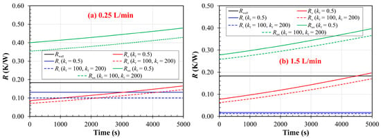
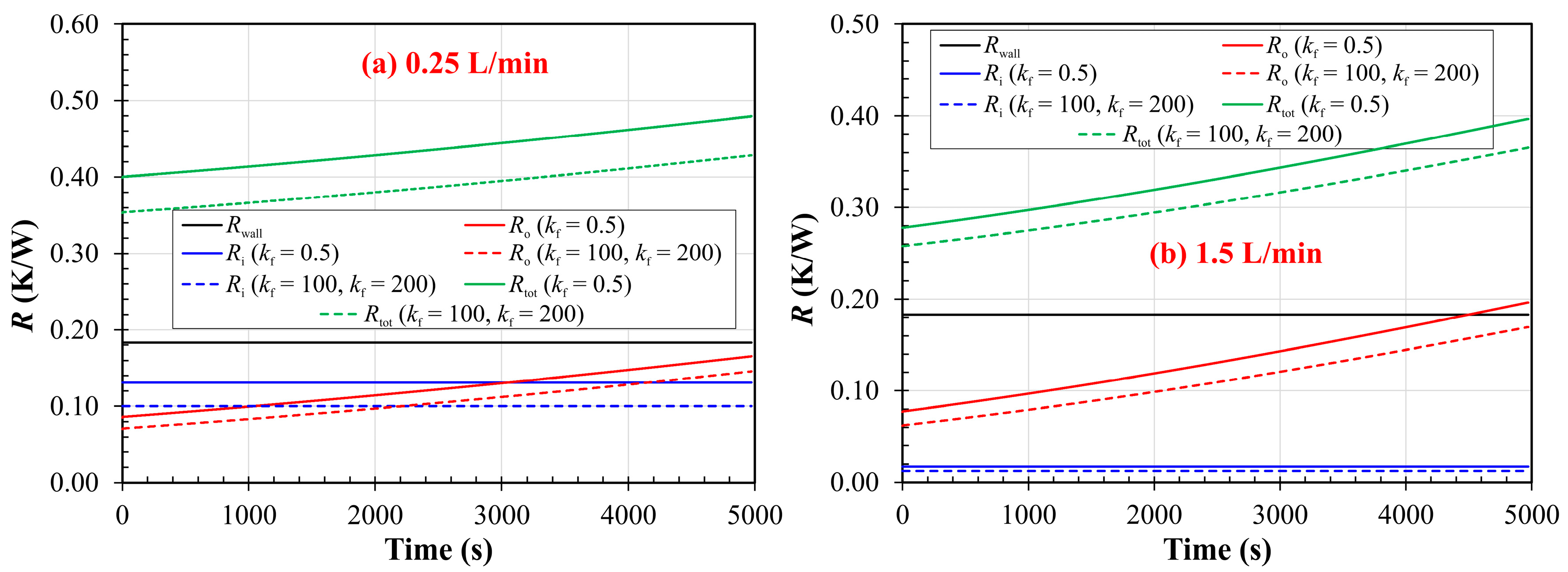
The total thermal resistance between the shell-side water and the coolant flow is composed of three main components: the internal convective resistance Ri, the conductive resistance through the tube wall Rwall, and the external convective resistance Ro. The time-dependent evolution of these components is presented in Figure 7 for coolant flow rates of 0.25 L/min and 1.5 L/min, representing laminar and turbulent internal flow regimes, respectively.
In the laminar case (Figure 8a), the internal heat transfer coefficient hi is nearly constant, resulting in a stable Ri value throughout the process. Since ho gradually decreases due to the narrowing temperature difference between the tube outer surface and the shell water, the external convective resistance Ro increases steadily. As a result, Ro becomes higher than Ri toward the end of the process. The wall resistance Rwall, governed solely by the thermal conductivity of the TPU material and geometric factors, remains constant over time. In the turbulent case (Figure 8b), the internal convective resistance Ri is substantially lower due to the high hi, making its contribution to the total resistance negligible. Similar to the laminar case, Ro increases over time and eventually dominates the total thermal resistance. This shift emphasises the critical role of external convection, particularly in the later stages of cooling when natural convection weakens.
Figure 8.
Time-dependent thermal resistance components for coolant flow rate of (a) 0.25 L/min and (b) 1.5 L/min.
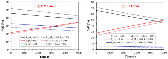
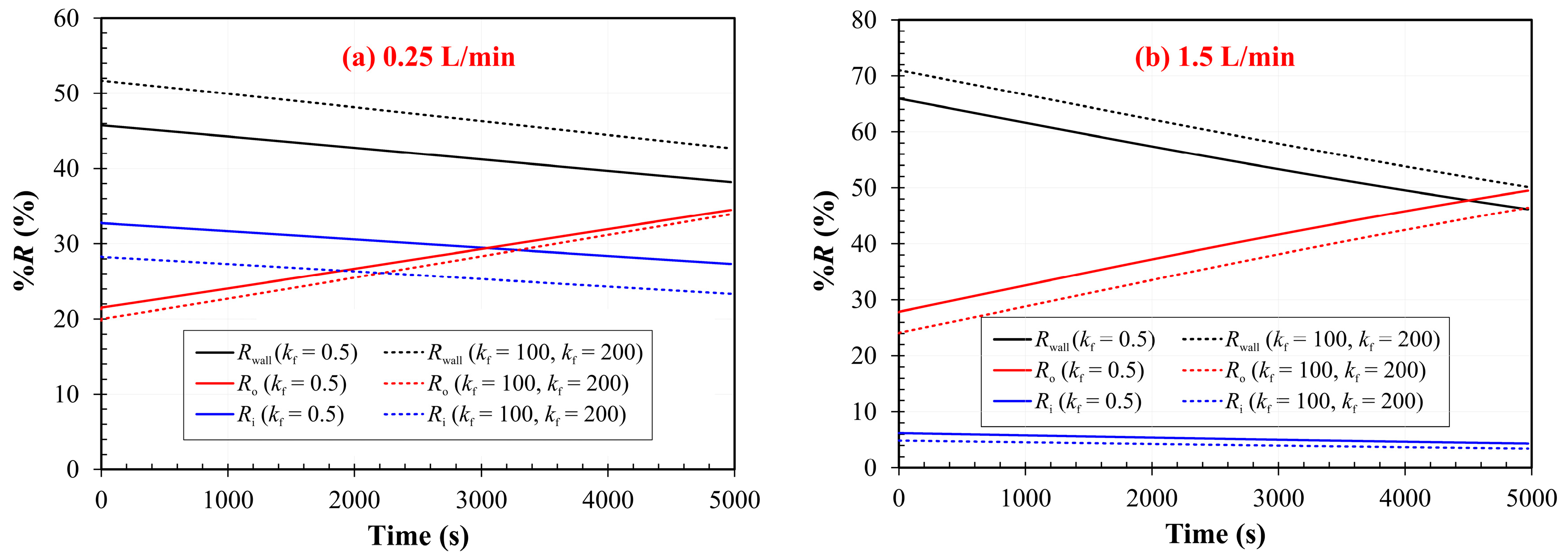
The relative contributions of each resistance component to the total thermal resistance Rtot are further illustrated in Figure 9. At lower flow rates, all three components contribute significantly, but as the flow rate increases, the share of Ri decreases while the relative impact of Ro and Rwall becomes more prominent. Notably, the tube wall, constructed from TPU with a low thermal conductivity of kt = 0.5 W/(m·K), contributes a considerable fraction of the total resistance, ranging from 38% to 52% depending on the flow rate and fin configuration.
Figure 9.
Percentage contribution of thermal resistance components over time at coolant flow rate of (a) 0.25 L/min and (b) 1.5 L/min.
This behaviour highlights a key limitation of using low-conductivity wall materials. Even in configurations with efficient fins and enhanced convection, the thermal bottleneck imposed by the wall remains significant. When high-conductivity fins are added, the proportion of Rwall becomes more dominant, especially under turbulent conditions where Ri is minimal.
In essence, the decomposition of the thermal resistance network reveals that enhancing fin conductivity and increasing flow rate can only partially mitigate thermal bottlenecks unless wall conductivity is also improved. This interplay between wall resistance, convective environments, and fin performance defines the overall thermal behaviour of the system.
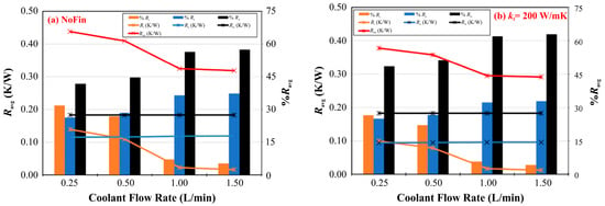
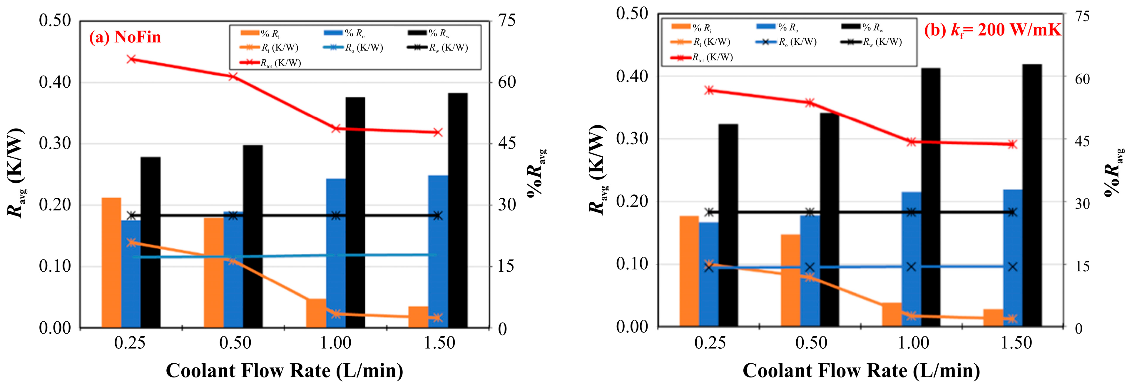
The average values of the thermal resistances and their percentage contributions to the total resistance over the first hour of operation are presented in Figure 10 as a function of the coolant flow rate. As expected, the tube wall resistance and the average shell-side convective resistance remain nearly constant with increasing flow rate. However, the total thermal resistance decreases significantly due to the reduction in internal convective resistance Ri, which diminishes with increasing flow rate as hi rises.
Figure 10.
Average thermal resistance and percentage contribution of resistance components versus coolant flow rate for (a) no fins and (b) fins with kf = 200 W/(m·K).
Interestingly, although the absolute values of the resistances vary between the finless and finned cases, the overall trend remains consistent. This similarity arises because the addition of fins (with kf = 200 W/(m·K)) alters the effective heat transfer areas but does not fundamentally alter the governing thermal resistances. When the relative contributions of the resistance components are analysed, a clear trend emerges. The share of Ri decreases with increasing flow rate, while the contributions of the wall resistance Rwall and external convective resistance Ro become more prominent. Among all components, the wall resistance remains the largest contributor to the total thermal resistance, especially in the presence of high-conductivity fins. This is attributed to the inherently low thermal conductivity of the TPU material (kt = 0.5 W/(m·K)), which acts as a thermal bottleneck regardless of flow or fin efficiency.
In the finless configuration, the contribution of the wall resistance to the total resistance ranges from 42% to 57% across the examined flow rates. When both internal and external fins with kf = 200 W/(m·K) are added, this share increases slightly, reaching 48% to 63% respectively. This increase is a result of the reduced Ri and Ro, which magnifies the relative impact of the wall resistance in the total resistance budget.
5.4. Overall Cooling Performance and Water Temperature Evolution
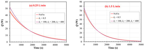
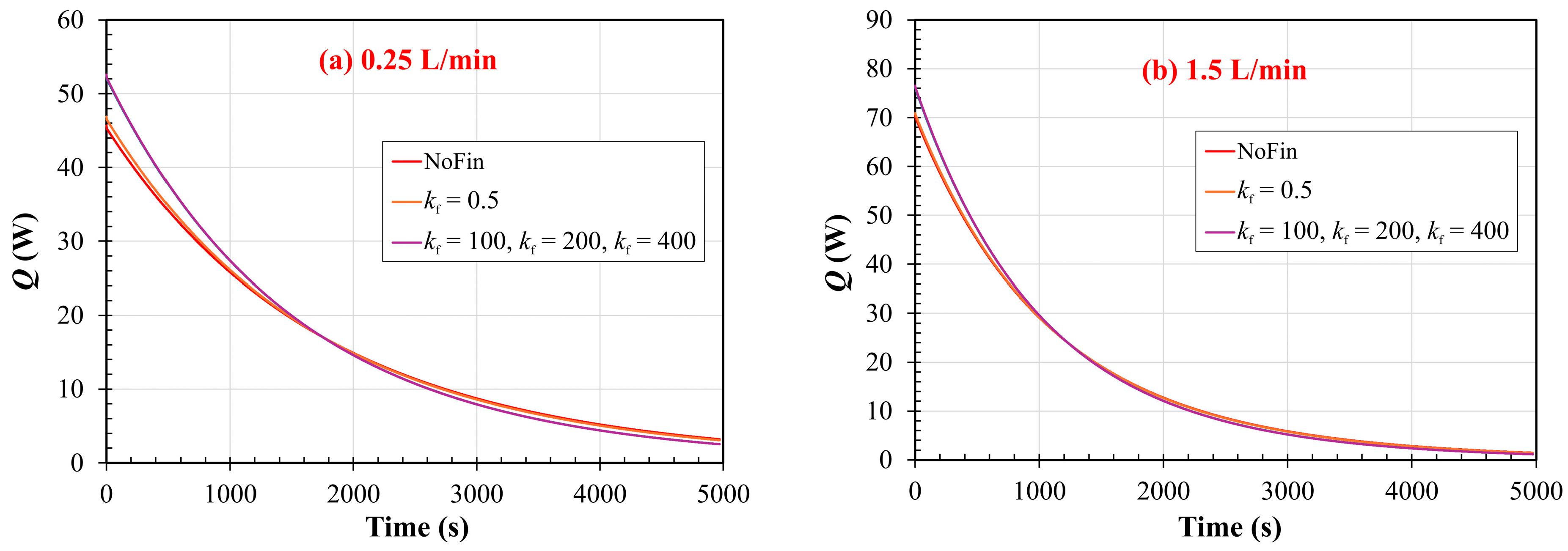
The transient heat transfer rate between the shell-side water and the internal coolant is shown in Figure 11 for two different flow rates. In both cases, the heat transfer rate decreases exponentially over time as the temperature difference between the water and the coolant diminishes. At the lower flow rate (Figure 11a), the overall heat transfer is limited by the internal convection and the thick thermal resistance across the tube wall. At the higher flow rate (Figure 11b), internal convection is greatly enhanced due to turbulence, resulting in a higher initial heat transfer rate and a more rapid energy removal from the shell-side water.
Figure 11.
Temporal variation in total heat transfer rate for coolant flow rate of (a) 0.25 L/min and (b) 1.5 L/min.
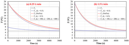
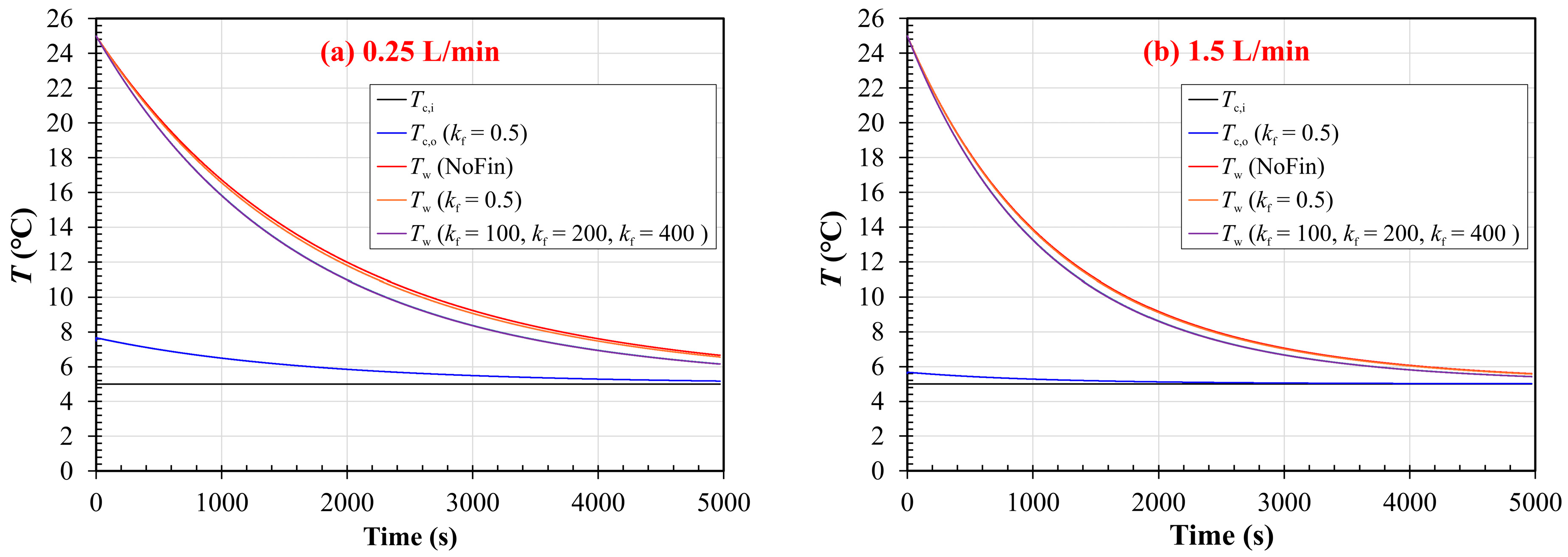
Figure 12 presents the time evolution of the inlet and outlet coolant temperatures as well as the shell water temperature for the two flow conditions. At the low flow rates, the coolant outlet temperature rises, indicating thermal gain by the fluid. Conversely, at high flow rates, the outlet temperature remains relatively low and close to the inlet value, reflecting a high heat capacity flow that removes energy more rapidly. In all cases, the water temperature decreases over time, with the rate of decrease being significantly faster at higher flow rates due to the dominant role of internal convective enhancement.
Figure 12.
Variation in coolant inlet/outlet and shell water temperatures with time at coolant flow rate of (a) 0.25 L/min and (b) 1.5 L/min.
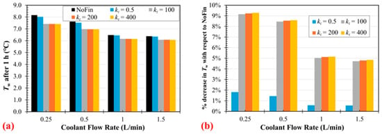
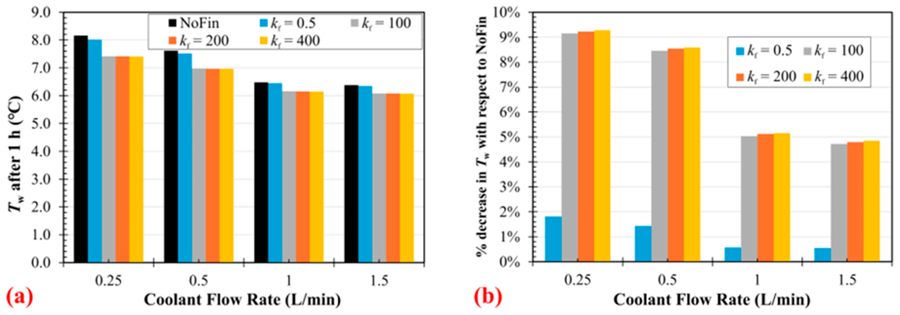
The influence of fin material thermal conductivity on the final cooling performance is further analysed in Figure 13. Figure 13a shows the water temperature after one hour of cooling for various flow rates. As expected, the lowest final water temperatures are achieved at the highest coolant flow rates. Figure 13b compares the percentage reduction in water temperature relative to the finless case. The addition of high-conductivity fins (e.g., kf = 200 W/(m·K)) enhances the cooling performance noticeably, especially at lower flow rates.
Figure 13.
Variation with coolant flow rate of (a) water temperature after 1 h and (b) percent decrease in water temperature after 1 h with respect to finless configuration (for fins spaced 5 mm apart).
Specifically, at 0.25 L/min, the presence of fins reduces the water temperature by approximately 9.2% compared to the finless configuration. However, this improvement diminishes at higher flow rates; at 1.5 L/min, the same fin configuration yields only about 4.7% reduction. This trend indicates that fins are most effective when the internal convection is weak (i.e., in laminar flow), and their relative contribution becomes less significant when turbulent convection dominates the overall heat transfer process.
Another important observation is that the benefit of increasing fin thermal conductivity beyond 100 W/(m·K) becomes negligible. For both low and high flow rates, the performance curves plateau after this point, suggesting that thermal resistance shifts away from the fin structure and becomes dominated by the tube wall and external convection limitations. This behaviour is consistent with the trends observed in the thermal resistance decomposition where the TPU tube wall remains the major barrier even when high-performance fins are used.
In summary, the overall cooling performance is dictated by a complex interplay between coolant flow rate, fin thermal conductivity, and system geometry. While fins significantly enhance thermal performance under low-flow conditions, their marginal benefit diminishes at higher flow rates unless accompanied by improvements in tube wall conductivity or external convection mechanisms.
5.5. Results for Fins Spaced 10 mm Apart
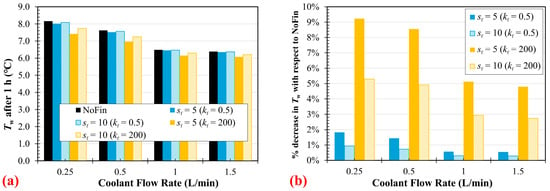
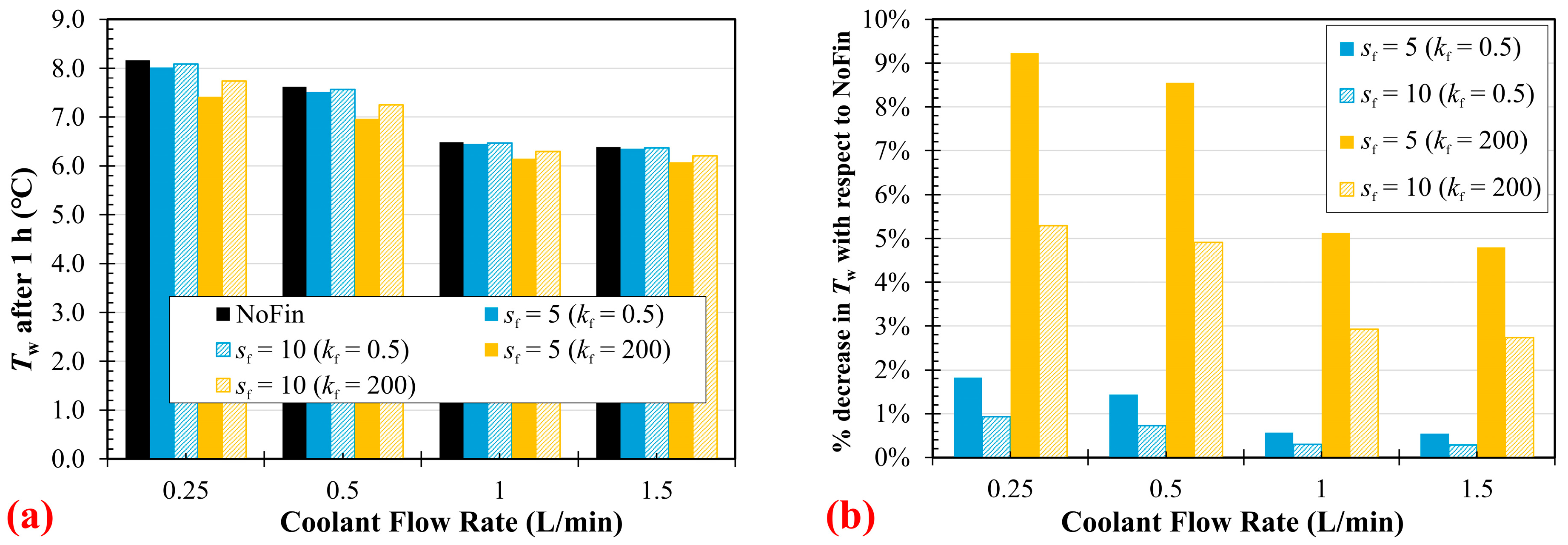
To evaluate the influence of fin spacing on the thermal performance of the system, a comparative analysis was conducted for two longitudinal fin spacings, spaced at 5 mm and 10 mm. While the 5 mm configuration represents a higher fin density and surface area enhancement, the 10 mm spacing provides insight into the diminishing returns of fin addition under identical thermal boundary conditions. As the fin spacing increases from 5 mm to 10 mm, the total effective surface area decreases, leading to an increase in total thermal resistance. In this case, both the internal (Ri) and external (Ro) convective resistances increase, while the wall resistance (Rwall) remains unchanged. This combined increase in convective resistance leads to a modest slowdown in the cooling rate of the shell-side water.
Figure 14 illustrates water temperature after 1 h (Figure 14a) and percentage temperature reduction relative to the finless baseline (Figure 14b). As fin spacing increases, the cooling performance diminishes. At low flow rates, the difference in cooling efficiency between the 5 mm and 10 mm configurations is more pronounced, reflecting the greater influence of fin surface area under laminar conditions. At higher flow rates, the gap narrows, indicating reduced sensitivity to fin spacing due to the dominance of forced convection in the overall heat transfer process.
Figure 14.
Variation with coolant flow rate of (a) water temperature after 1 h and (b) percent decrease in water temperature after 1 h with respect to finless configuration (for fins spaced 10 mm apart).
6. Experimental Study
The objective of the experimental study was to compare the heat extraction performance of four flexible tubular heat exchanger configurations submerged in water. Both laminar (plain tube) and internally modified, turbulence-promoting configurations were evaluated.
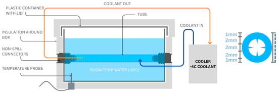
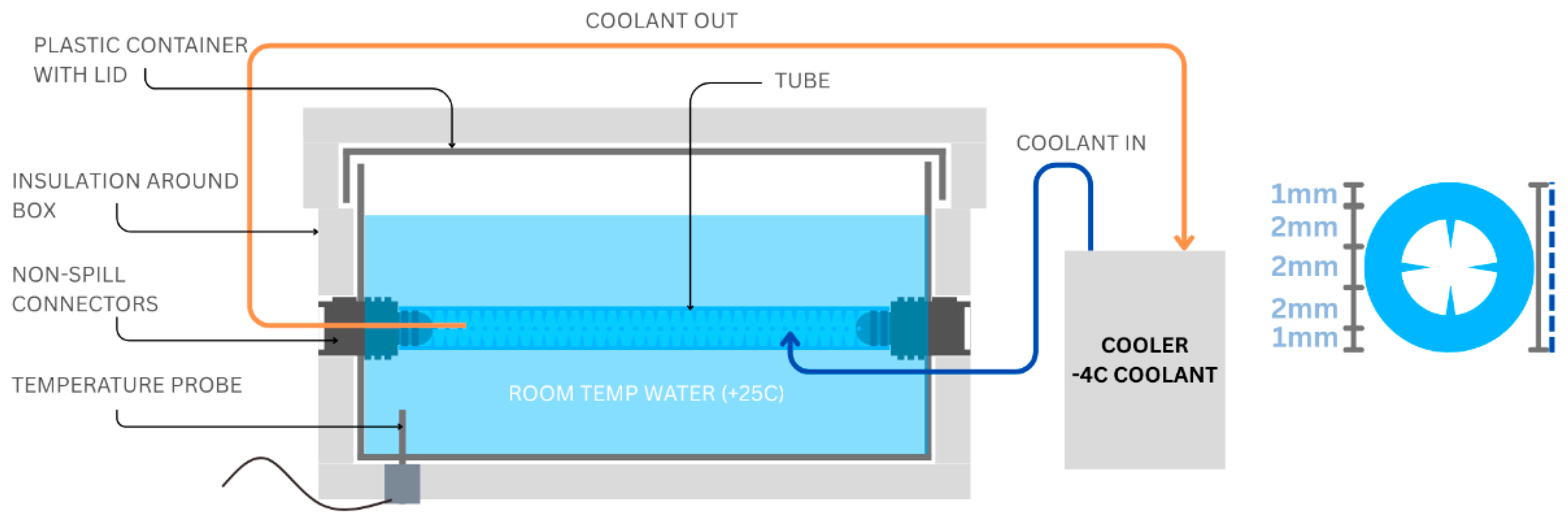
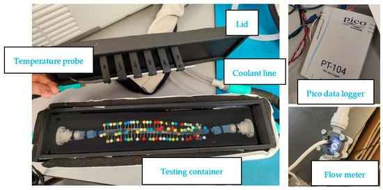
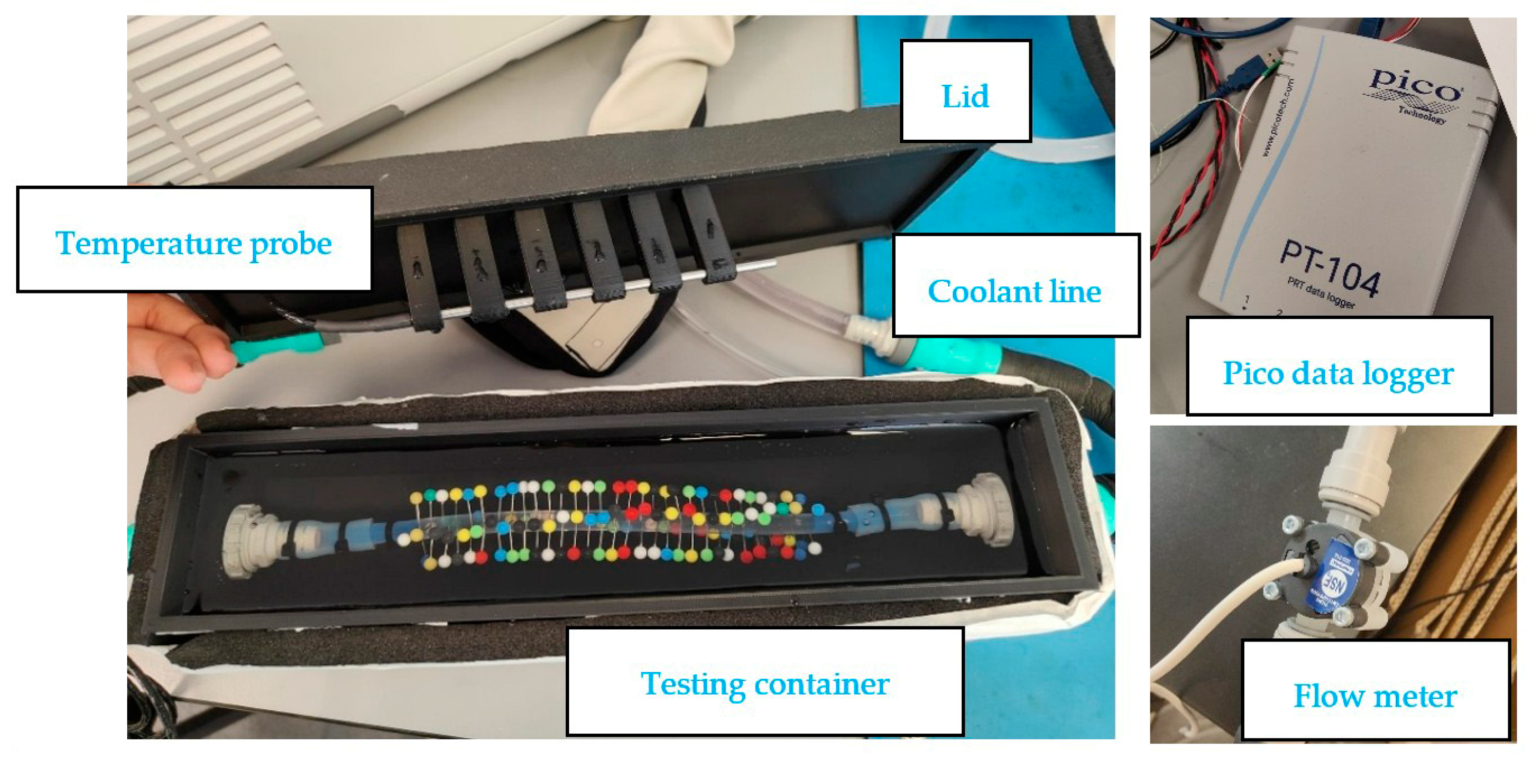
A 3D-printed, insulated liquid chamber with a 1 L internal volume was used as the test rig (Figure 15). The chamber was fitted with inlet and outlet connectors for the test tube and insulated externally using Armaflex tape to minimise heat loss. A Paxman Limb Cryo-compression System (PLCS) circulated coolant at a constant 5 °C through the tube. The initial water temperature in the chamber was 23–25 °C for all tests (Figure 16).
Figure 15.
Illustration showing the configuration of physical test rig.
Figure 16.
Images showing experimental setup-technical testing equipment.
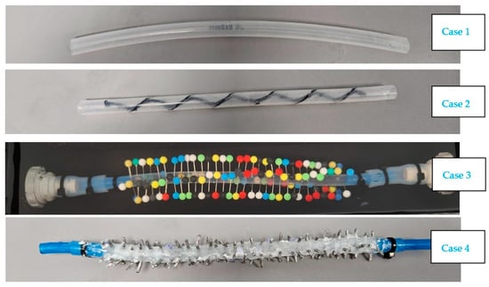
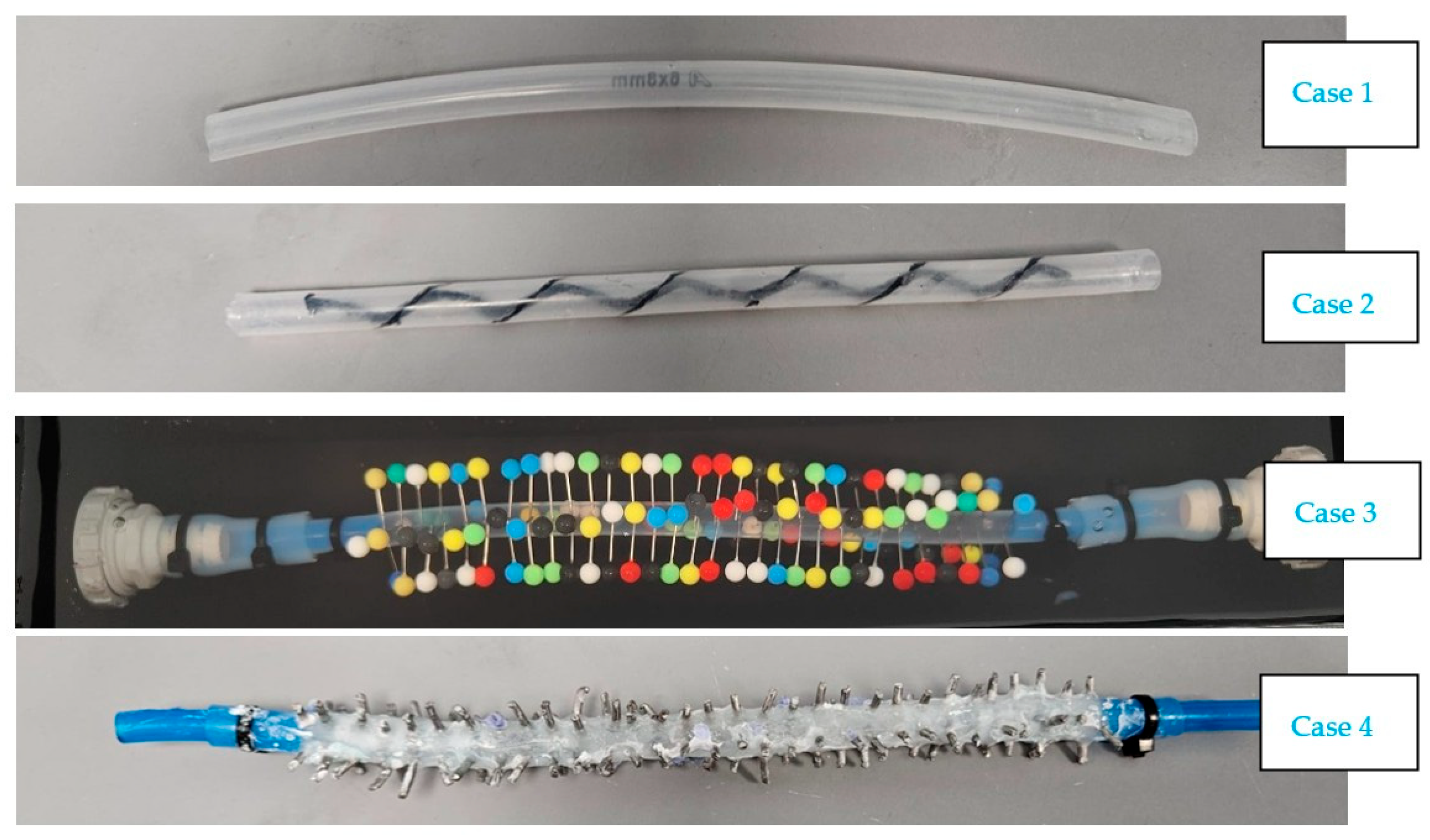
A digital thermistor (±0.1 °C) was positioned near the geometric centre of the chamber to record water temperature every second via a Pico PT104 data logger. The coolant flow rate was measured using an inline flow meter located downstream of the test chamber. Ambient temperature and humidity were continuously monitored in a temperature-controlled laboratory (25 °C). The 1 L water volume was gently agitated using an integrated mechanical stirrer to minimise thermal stratification, without disturbing the sealed test environment. A parallel control experiment with an identical setup but no active cooling was used to quantify ambient heat gains and enable accurate calculation of net heat exchange. Each tested heat exchanger consisted of a 250 mm-long TPU tube with a 6 mm internal diameter and 1 mm wall thickness. Four internal and external circular fins (1.5 mm diameter, 2 mm height) were evenly spaced at 5 mm intervals along the tube length. The tube was fully submerged in the insulated chamber. Cooling water was circulated continuously through the tube at a constant inlet temperature. Four tube configurations were tested (Figure 17):
Figure 17.
Flexible heat exchanger tubes.
- Case 1: Plain TPU tube
- Case 2: Plain TPU tube with 3D-printed internal spiral insert
- Case 3: TPU tube with nickel-plated steel pins-fin tentacles featuring large spherical heads
- Case 4: TPU tube with aluminium pin-fin inserts
Each test ran for 1 h, with tank water temperature recorded every second. A control tank (no cooling) quantified ambient heat gains. The resulting temperature–time data were used to determine cooling performance and compare heat extraction rates among the four configurations. A 1D transient energy balance model was developed to support interpretation, incorporating convective heat transfer through the tube’s internal surface, conduction through the TPU wall, and enhanced transfer via the internal structures.
7. Experiment Results and Discussion
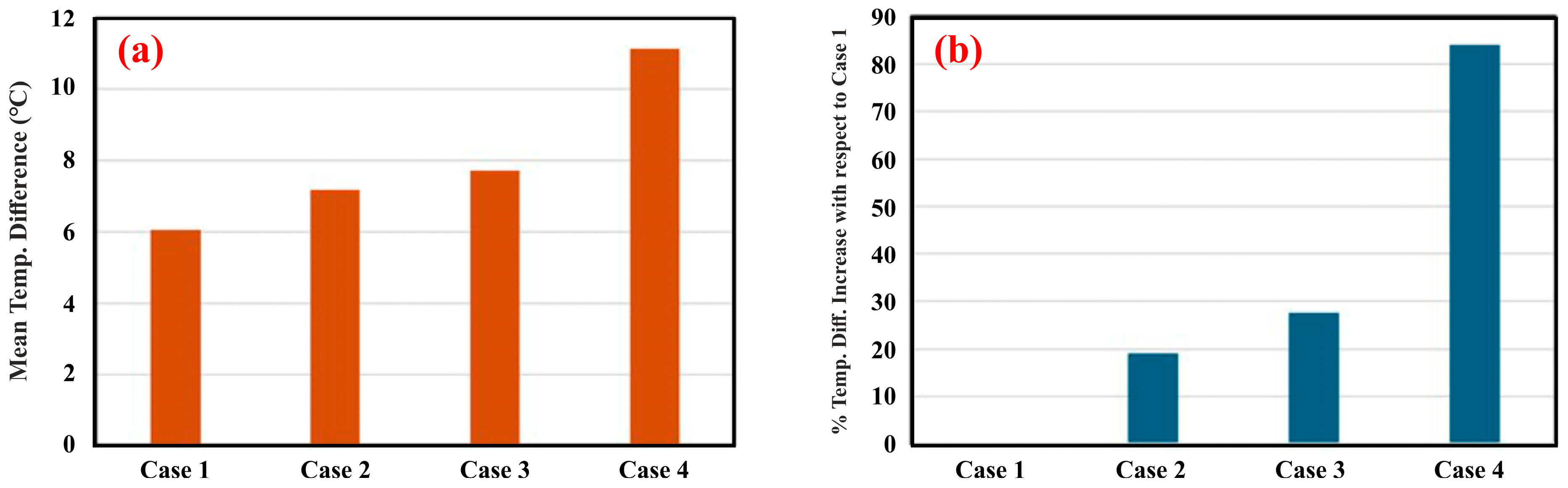
Each configuration (Cases 1–4) was tested three times to assess repeatability. Table 2 reports the mean parameters measured for each case (arithmetic average of the three replicates). Figure 18 compares the mean temperature difference () across the tank for four configurations, where .
Table 2.
Comparative results of case studies.
Figure 18.
Mean (a) and temperature (b) differences obtained for four cases.
For the plain TPU tube (Case 1), the temperature in the tank drops by about 6 °C, over the test period (Figure 18a). Adding internal structures using 3D-printed internal spiral (Case 2) = 7.2 °C, aluminium-core tentacles with spherical heads (Case 3) = 7.7 °C, and aluminium pin-fin inserts (Case 4) = 11.1 °C, all outperform the plain tube where the pin-fin inserts deliver the largest effect. To quantify the relative impact of the inserts.
Figure 18b reports the percentage increase in with respect to the plain tube (Case 1). Compared to Case 1, Case 2 increases by 19%, Case 3 by 27.5%, and Case 4 by 84%. These results clearly demonstrate the thermal enhancement achieved by introducing internal structures, with the aluminium pin-fin geometry providing the strongest improvement among the tested options.
To further assess the predictive capability of the numerical model, a comparison was carried out under the experimental conditions corresponding to Case 4. The model was adjusted to match the operating parameters of the experiment, including flow rate and boundary conditions. Under these conditions, the numerical model predicts a final water temperature of 11.66 °C after 1 h, while the experimentally measured value is 12.73 °C (Table 2). This corresponds to a deviation of approximately 8.4%. Given the simplifying assumptions of the model, including uniform flow distribution, neglect of secondary flow structures induced by the fins, and idealised boundary conditions, this level of agreement is considered acceptable. The result further supports the ability of the model to capture the dominant thermal behaviour of the system and confirms its suitability as a predictive design tool.
8. Conclusions
Working closely with scientists who specialise in heat extraction has enabled the team to define clear parameters that designers can confidently use when exploring new configuration possibilities. This collaboration ensured a shared understanding of thermal constraints and performance targets, allowing design decisions to be grounded in robust technical insight. Computational Fluid Dynamics (CFD) and simulation studies further reinforced this approach, demonstrating that incorporating the proposed design modifications can deliver more than a 50% increase in cooling efficiency.
Designers play a crucial role in translating these scientific parameters into viable commercial applications by balancing performance, practicality, and user desirability. Their ability to integrate technical constraints with real-world requirements ensures that the resulting solutions are not only functional but also manufacturable and appealing. The relevance of this work is already being recognised, with an SME in the medical sector actively investigating how such advanced cooling structures could be embedded within their products to enhance thermal management.
A transient thermal model and a series of physical experiments were used to investigate the effect of circular pin fins and fin material thermal conductivity on the cooling performance of flexible TPU tubes submerged in water. The model accounted for internal forced convection, radial conduction through the low-conductivity tube wall, and external natural convection, with fins modelled via surface area enhancement and efficiency factors. Although the numerical and experimental investigations were conducted under slightly different geometric configurations and operating conditions, a direct quantitative comparison between the two approaches is not intended. Nevertheless, both studies consistently reveal the same qualitative trend: the incorporation of aluminium fins, both inside and outside TPU tube, leads to a more pronounced reduction in the tank water temperature compared to the plain tube configuration. The numerical simulations generally predict a lower temperature reduction than that observed experimentally. This discrepancy can be attributed to the idealised modelling assumptions, including simplified representations of fin-induced flow disturbances inside the tube and the limited consideration of natural convection enhancement on the external tube surface. Although the numerical model does not resolve detailed flow structures induced by the fins, it successfully captures the dominant heat transfer trends observed experimentally.
Despite these simplifications, the model provides a physically consistent, first-order representation of the coupled heat transfer mechanisms governing the system. The consistent agreement in performance trends between numerical and experimental results supports the validity of the modelling approach as a predictive design-oriented tool for evaluating flexible and bio-inspired heat exchanger configurations. The experimental results serve as supporting validation of the dominant thermal trends predicted by the model, particularly under representative operating conditions.
The variation in hi and ho demonstrates that the system behaviour is governed by the relative dominance of internal and external convective mechanisms rather than temperature trends alone. The combined numerical and experimental investigations showed that fin geometry, material conductivity, and coolant flow rate collectively determine the cooling performance of flexible tubular heat exchangers. The plain TPU tube exhibited the slowest cooling response, highlighting the influence of internal convective limitations and the wall’s thermal resistance. Incorporating internal fins particularly aluminium-based structures significantly improved heat transfer by increasing the effective surface area and promoting turbulence within the tube. The findings confirm that finned TPU heat exchangers can substantially enhance convective heat transfer while maintaining mechanical flexibility an essential requirement for wearable and medical cooling applications. The results also indicate that further performance gains depend primarily on reducing the thermal resistance of the TPU wall, for example through composite materials or high-conductivity coatings.
Overall, this study establishes a design framework for flexible, geometrically enhanced TPU tubing capable of delivering rapid, uniform, and energy-efficient cooling. Such systems have strong potential for integration into next-generation wearable thermal management devices, where compactness, comfort, and responsiveness are critical.
Limitations and Future Work
The present study assumes ideal thermal insulation and a constant coolant inlet temperature, conditions that may differ from real-world wearable applications. In addition, the analysis focuses primarily on thermal performance and does not explicitly quantify pressure drop or pumping power. This is mainly due to the low flow rates and short tube lengths typical of wearable applications, where hydraulic losses are expected to be minimal. In addition, the available experimental instrumentation did not allow accurate measurement of very small pressure differences. Future work should incorporate detailed hydraulic analysis, particularly for extended tube lengths or higher flow rates where pressure losses may become more significant. These assumptions may influence the absolute magnitude of predicted temperatures and heat transfer rates; however, they do not affect the ability of the model to capture the dominant heat transfer trends and relative performance differences between configurations.
Future work should consider transient inlet conditions, variable external heat loads, and user-related factors such as tube bend radius, local pressure points, comfort, and safety. Mechanical fatigue and potential delamination of tentacle structures under repeated flexion should also be investigated to assess long-term durability in dynamic environments. Integrating these flexible heat exchangers into full garment systems and evaluating their performance in human subject trials would provide an important step towards clinical and commercial deployment. The teams could investigate integration of smart materials such as graphene into the internal structures of the tubes to increase the energy extraction.
As the mathematical model is refined, it will enable streamlined design inputs that significantly accelerate iterative development cycles. This structured approach supports rapid exploration of solution spaces while maintaining confidence in performance outcomes. Complementing the model, Excel-based tools can be generated to deliver optimal parameters and boundary conditions, helping guide teams toward workable and innovative solutions across both current and future design developments.
Author Contributions
E.U. and O.H. Conceptualisation; E.U. and J.B. study design, data gathering, first draft writing, and final version approval. N.G., O.B., Y.E.G. and U.O., mathematical model, manuscript writing and review, O.H. experiment setup, writing, review, and editing of the final version. All authors have read and agreed to the published version of the manuscript.
Funding
This research was supported by Innovate UK through the “Smart grant” scheme (10120369) in UK and by Paxman R&D.
Data Availability Statement
The data presented in this study are available on request from the corresponding author due to legal reasons.
Acknowledgments
We are grateful to Paxman Coolers for their ongoing support of the R&D team and activities, and for their engagement as stakeholders and shareholders. We also acknowledge the technical assistance of Riley Irving.
Conflicts of Interest
Authors Ertu Unver and Jonathan Binder were employed by Paxman Coolers. The remaining authors declare that the research was conducted in the absence of any commercial or financial relationships that could be construed as a potential conflict of interest. The authors declare that this study received funding from “Innovate UK” through the “Smart Grants”. The funder was not involved in the study design, collection, analysis, interpretation of data, the writing of this article, or the decision to submit it for publication.
References
- Ahmed, A.; Jalil, M.A.; Hossain, M.M.; Moniruzzaman, M.; Adak, B.; Islam, M.T.; Mukhopadhyay, S. A PEDOT: PSS and graphene-clad smart textile-based wearable electronic Joule heater with high thermal stability. J. Mater. Chem. C 2020, 8, 16204–16215. [Google Scholar] [CrossRef] [Scilit]
- Ates, H.C.; Nguyen, P.Q.; Gonzalez-Macia, L.; Morales-Narváez, E.; Güder, F.; Collins, J.J.; Dincer, C. End-to-end design of wearable sensors. Nat. Rev. Mater. 2022, 7, 887–907. [Google Scholar] [CrossRef] [Scilit]
- Nemomssa, H.D.; Bossuyt, F.; Vandecasteele, B.; De Pauw, H.; Gidi, N.W.; Bauwens, P. Revolutionizing patient care: A comprehensive review of recent advances in flexible printed heaters for wearable medical applications. Actuators 2024, 14, 1. [Google Scholar] [CrossRef] [Scilit]
- Sattar, M.; Yeo, W.H. Recent advances in materials for wearable thermoelectric generators and biosensing devices. Materials 2022, 15, 4315. [Google Scholar] [CrossRef] [Scilit] [PubMed]
- Ardeta, L.G.A.; Doma, B., Jr. Numerical Analysis of Passive, Compound, and Active Augmented Heat Transfer Methods for Concentric Tube Heat Exchanger. Appl. Sci. 2025, 15, 4701. [Google Scholar] [CrossRef] [Scilit]
- Nitturi, L.K.; Kapu, V.K.; Gugulothu, R.; Kaleru, A.; Vuyyuri, V.; Farid, A. Augmentation of heat transfer through passive techniques. Heat Transf. 2023, 52, 4422–4449. [Google Scholar] [CrossRef] [Scilit]
- Bhattacharyya, S.; Vishwakarma, D.K.; Srinivasan, A.; Soni, M.K.; Goel, V.; Sharifpur, M.; Ahmadi, M.H.; Issakhov, A.; Meyer, J. Thermal performance enhancement in heat exchangers using active and passive techniques: A detailed review. J. Therm. Anal. Calorim. 2022, 147, 9229–9281. [Google Scholar] [CrossRef] [Scilit]
- Ho, M.L.G.; Oon, C.S.; Tan, L.L.; Wang, Y.; Hung, Y.M. A review on nanofluids coupled with extended surfaces for heat transfer enhancement. Results Eng. 2023, 17, 100957. [Google Scholar] [CrossRef] [Scilit]
- Cabeza, L.F.; Mani Kala, S.; Zsembinszki, G.; Vérez, D.; Risco Amigó, S.; Borri, E. Development of a bio-inspired TES tank for heat transfer enhancement in latent heat thermal energy storage systems. Appl. Sci. 2024, 14, 2940. [Google Scholar] [CrossRef] [Scilit]
- Yang, H.; Pi, J.; Park, S.; Bae, W. Bioinspired Heat Exchangers: A Multi-Scale Review of Thermo-Hydraulic Performance Enhancement. Biomimetics 2026, 11, 76. [Google Scholar] [CrossRef] [Scilit]
- Unver, E.; Clayton, J.E.; Clear, N.; Huerta, O.; Binder, J.; Paxman, C.; Paxman, R. The challenges of implementing design research within SME based medical product development: Paxman scalp cooling case study. Des. Health 2022, 6, 4–27. [Google Scholar] [CrossRef] [Scilit]
- Liu, J.; Zhai, H.; Li, J.; Li, Y.; Liu, Z. Enhancing wearable electronics through thermal management innovations. Wearable Electron. 2024, 1, 160–179. [Google Scholar] [CrossRef] [Scilit]
- Yun, J.H.; Yoo, Y.J.; Kim, H.R.; Song, Y.M. Recent progress in thermal management for flexible/wearable devices. Soft Sci. 2023, 3, 12. [Google Scholar] [CrossRef] [Scilit]
- Zhou, Q.; Wang, H.; Wu, F.; Liu, S.; Wei, H.; Hu, G. Numerical Investigation of Enhanced Heat Transfer with Micro Pin Fins in Heat Exchangers. Micromachines 2024, 15, 1120. [Google Scholar] [CrossRef] [Scilit] [PubMed]
- Persoons, T.; Saenen, T.; Van Oevelen, T.; Baelmans, M. Effect of Flow Pulsation on the Heat Transfer Performance of a Mini-channel Heat Sink. ASME J. Heat Transfer. 2012, 134, 091702. [Google Scholar] [CrossRef] [Scilit]
- Wang, K.; Shi, Y.; Chen, J.; Dai, Y. A Biomimetic Microchannel Heat Sink for Enhanced Thermal Performance in Chip Cooling. Biomimetics 2025, 10, 459. [Google Scholar] [CrossRef] [Scilit]
- Aljuhani, Y.; Guner, A.; Abdelwahab, A.; Essa, K. Bio-inspired heat exchanger fabricated using additive manufacturing: Numerical and experimental investigation. Appl. Therm. Eng. 2026, 289, 129968. [Google Scholar] [CrossRef] [Scilit]
- Huang, Z.; Hwang, Y.; Radermacher, R. Review of nature-inspired heat exchanger technology. Int. J. Refrig. 2017, 78, 1–17. [Google Scholar] [CrossRef] [Scilit]
- Luo, Y.; Li, G.; Bennett, N.S.; Luo, Z.; Munir, A.; Islam, M.S. Heat Transfer Enhancement in Heat Exchangers by Longitudinal Vortex Generators: A Review of Numerical and Experimental Approaches. Energies 2025, 18, 2896. [Google Scholar] [CrossRef] [Scilit]
- Dabrowska, A.; Kobus, M.; Sowiński, P.; Starzak, Ł.; Pękosławski, B. Integration of Active Clothing with a Personal Cooling System within the NGIoT Architecture for the Improved Comfort of Construction Workers. Appl. Sci. 2024, 14, 586. [Google Scholar] [CrossRef] [Scilit]
- Zhang, N.; Wang, Z.; Zhao, Z.; Zhang, D.; Feng, J.; Yu, L.; Lin, Z.; Guo, Q.; Huang, J.; Mao, J.; et al. 3D printing of micro-nano devices and their applications. Microsyst. Nanoeng. 2025, 11, 35. [Google Scholar] [CrossRef] [Scilit] [PubMed]
- Yang, B.; Zhang, X.; Ji, J.; Jiang, M.; Zhao, Y. A comprehensive review of phase change material-based wearable devices for personal thermal management: Mechanism, location and application functionality. Appl. Therm. Eng. 2024, 257, 124416. [Google Scholar] [CrossRef] [Scilit]
- Jabbour, J.; Russeil, S.; Mobtil, M.; Bougeard, D.; Lacrampe, M.-F. High performance finned-tube heat exchangers based on filled polymer. Appl. Therm. Eng. 2019, 155, 620–630. [Google Scholar] [CrossRef] [Scilit]
- Cheng, X.; Shen, Z.; Zhang, Y. Bioinspired 3D flexible devices and functional systems. Natl. Sci. Rev. 2024, 11, nwad314. [Google Scholar] [CrossRef] [Scilit]
- Binder, J.; Unver, E.; Clayton, J.; Burke, P.; Paxman, R.; Sundar, R.; Bandla, A. A Limb Hypothermia Wearable for Chemotherapy-Induced Peripheral Neuropathy: A Mixed-Methods Approach in Medical Product Development. Front. Digit. Health 2020, 2, 573234. [Google Scholar] [CrossRef] [Scilit]
- Çengel, Y.A.; Ghajar, A.J. Heat and Mass Transfer: Fundamentals and Applications, 6th ed.; McGraw-Hill: Columbus, OH, USA, 2020. [Google Scholar]
- Bergman, T.L.; Lavine, A.S.; Incropera, F.P.; DeWitt, D.P. Fundamentals of Heat and Mass Transfer, 7th ed.; John Wiley & Sons: Hoboken, NJ, USA, 2017. [Google Scholar]
- Edwards, D.K.; Denny, V.E.; Mills, A.F. Transfer Processes, 2nd ed.; Hemisphere: Washington, DC, USA, 1979. [Google Scholar]
- Yan, Z.; Oon, C.S.; Tan, B.T.; Ooi, J.B. Geometric design and optimization of extended surfaces for enhanced heat transfer: A comprehensive review. Results Eng. 2025, 27, 106227. [Google Scholar] [CrossRef] [Scilit]
- Churchill, S.W.; Chu, H.H.S. Correlating equations for laminar and turbulent free convection from a horizontal cylinder. Int. J. Heat Mass Transf. 1975, 18, 1049–1053. [Google Scholar] [CrossRef] [Scilit]



Disclaimer/Publisher’s Note: The statements, opinions and data contained in all publications are solely those of the individual author(s) and contributor(s) and not of MDPI and/or the editor(s). MDPI and/or the editor(s) disclaim responsibility for any injury to people or property resulting from any ideas, methods, instructions or products referred to in the content. |
© 2026 by the authors. Licensee MDPI, Basel, Switzerland. This article is an open access article distributed under the terms and conditions of the Creative Commons Attribution (CC BY) license.