


Abstract
This paper investigates the dynamic behavior of synchronous machines subjected to sudden short circuits. Initially, the case of a single-phase synchronous machine under open-circuit conditions is studied. Analytical derivations of short circuit current expressions are carried out and evaluated using numerical integration methods on a digital computer. The transient responses of both armature and field currents are analyzed, showing their dependence on rotor position and machine parameters. A SIMULINK model is developed to simulate and visualize these responses. Subsequently, the study extends to the case of a line-to-line short circuit in a three-phase synchronous machine with damper windings. The general voltage equations of the three-phase machine are derived and applied to the problem, with numerical integration and SIMULINK simulations confirming analytical insights. Results highlight the key influence of rotor angle, leakage inductance, and damper windings on the dynamics of short circuit currents.
1. Introduction
Synchronous machines are fundamental components in modern electric power systems, acting as the primary energy converters in large-scale power generation plants as well as in high-performance industrial drives. Their importance stems not only from their ability to deliver stable electrical power but also from their critical role in maintaining grid stability. Due to their direct connection with the power grid, the operational reliability of synchronous machines is of paramount importance. Any disturbance in their operation, such as sudden load changes, voltage dips, or faults, can significantly affect both machine integrity and overall system stability [1].
One of the most severe disturbances a synchronous machine can experience is a sudden short circuit. When such a fault occurs, the machine is subjected to very large transient currents that decay over time but can initially reach magnitudes several times higher than the steady-state current. These high currents generate strong electromechanical stresses within the stator and rotor windings, potentially leading to insulation damage, overheating, excessive vibrations, and even permanent machine failure. Furthermore, these transients can propagate through the power system, creating voltage instability, mechanical torque oscillations, and disturbances in interconnected generators and loads [2].
The study of synchronous machine fault behavior has been an active area of research for nearly a century. A major milestone was the introduction of Park’s transformation in 1929, which reformulated the machine’s equations into a rotating reference frame. This transformation simplified the analysis of transient and steady-state behavior by converting the three-phase machine equations into a two-axis (d-q) model, laying the foundation for modern analysis methods. Subsequent research efforts have focused on refining analytical models, incorporating damper windings, and improving the accuracy of transient response prediction. With the advent of digital computing, numerical techniques such as Runge-Kutta integration methods were introduced to solve the machine’s nonlinear differential equations, enabling more precise analysis of dynamic fault behavior [3].
In recent decades, simulation-based approaches have become indispensable tools in the analysis and study of synchronous machines. Advanced software environments, such as MATLAB/Simulink (V. 24A), enable engineers and researchers to develop detailed and flexible machine models, simulate sudden short-circuit events, and evaluate system responses under a wide range of operating conditions [4].
These computational frameworks provide in-depth insight into key transient phenomena, including current waveform evolution, electromagnetic torque oscillations, and the influence of structural elements such as damper windings and excitation systems. Furthermore, they facilitate a systematic investigation of parameter sensitivity and dynamic interactions within the machine [5].
In addition, simulation platforms offer the possibility to design, implement, and validate control strategies and fault mitigation techniques in a controlled and risk-free environment. This significantly reduces development costs and technical risks, while ensuring that proposed solutions can be thoroughly assessed prior to their deployment in practical, real-world applications [6].
The present work focuses on modeling and analyzing the sudden short circuit response in both single-phase and three-phase synchronous machines. The single-phase study serves as an introductory step, providing a simplified model that illustrates fundamental transient mechanisms. Building on this foundation, the analysis is extended to three-phase synchronous machines, where the inclusion of damper windings and field dynamics provides a more realistic representation of practical machines. Both analytical methods and time-domain simulations are employed, enabling a comparative understanding of theoretical predictions and simulated behaviors [7].
By combining classical analysis with modern simulation techniques, this study aims to provide a deeper understanding of fault dynamics in synchronous machines, highlighting both the fundamental principles and the practical implications for machine design, protection, and system stability. Additionally, the model enables the examination of how key parameters—such as inductance variation and initial operating conditions—influence the amplitude and decay of transient currents during the fault event [8].
2. Mathematical Modeling of Synchronous Machines
2.1. Single-Phase Machine
When a sudden short circuit occurs at the terminals of a synchronous machine, significant transient currents are generated due to the abrupt change in armature operating conditions. For analytical purposes, the behavior can first be examined using a simplified single-phase representation. In this approach, the model accounts for the self-inductances of both the field and armature windings, as well as their mutual inductance, which varies as a function of the relative angular position between their magnetic axes [9].
This section develops a mathematical model describing the dynamic response of a single-phase synchronous machine under sudden short-circuit conditions. The formulation begins with the fundamental voltage equations of the field and armature circuits. It then incorporates the relationships between currents, flux linkages, and the position-dependent mutual inductance. By systematically combining these elements, a system of differential equations governing the transient behavior is derived [10].
These equations provide a rigorous foundation for understanding fault-induced dynamics and serve as a basis for extending the analysis to more complex three-phase synchronous machine models [11].
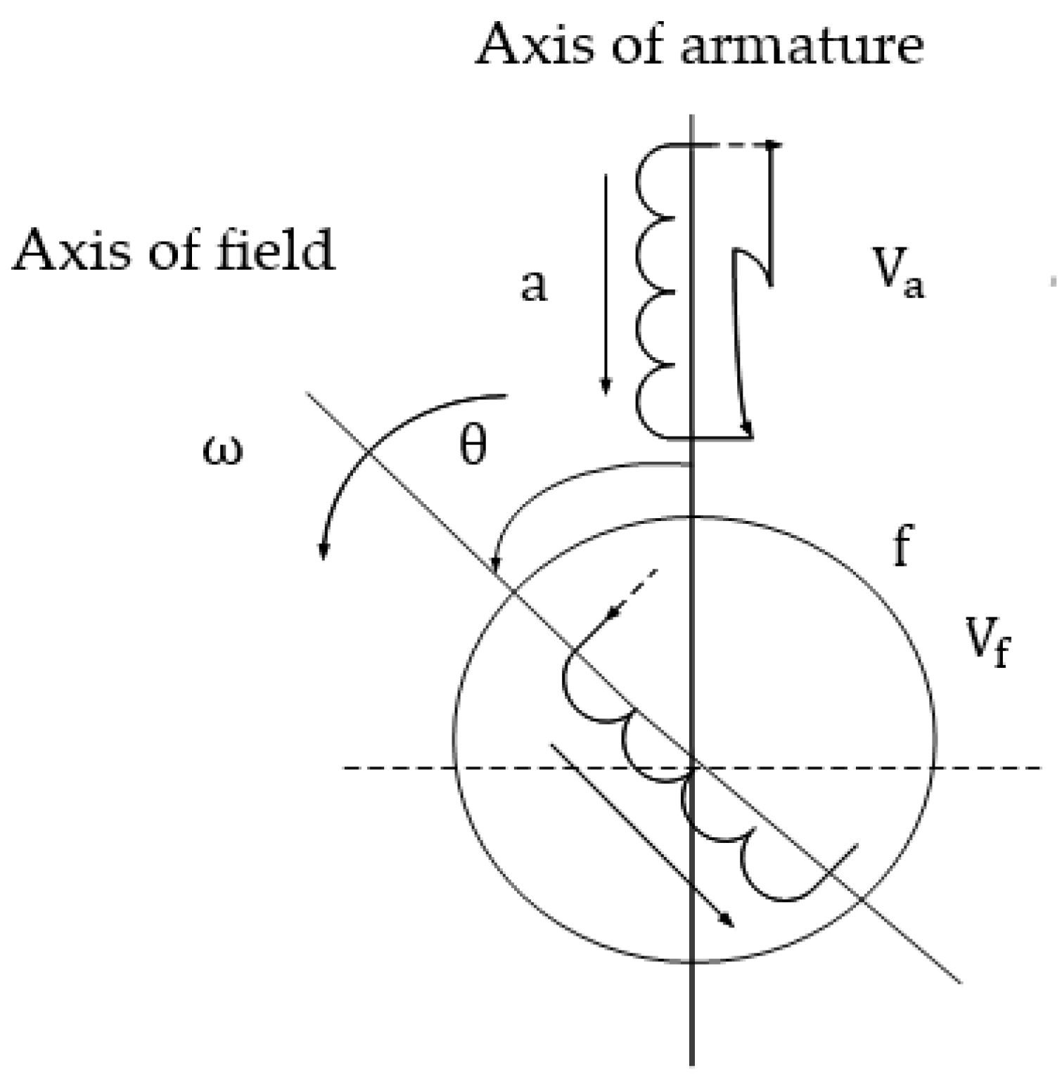
The machine in Figure 1 has constant self-inductance and of the two winding while the mutual inductance between them is pure cosine function of the angle between their axes [12].
The armature winding is initially open, when a sudden short circuit occurs at its terminal. so that . The initial value of field current is .
But for armature
When short circuit
Multiply Equation (10) by and Equation (12) by then arrange them [13]:
Put () from Equation (14) in the left-hand side and then substitute Equation (13):
Multiply Equation (10) by and Equation (12) by then arrange them [14]:
Put () from Equation (20) in the left-hand side and then substitute Equation (19)
Equations (27) and (28) represented to main equation used to find dynamic response of short circuit current in single phase synchronous machine.
Figure 1.
Single phase synchronous machine.
2.2. Three-Phase Synchronous Machine with Damper Windings
In three-phase synchronous machines, a line-to-line short circuit is one of the most critical disturbances that can occur. Unlike the single-phase case, where only one armature winding is considered, the three-phase configuration involves mutual coupling between multiple windings on both the stator and rotor. This results in a more complex set of equations describing the transient currents and voltages during the fault [15].
In the event of a short circuit occurring between two stator phases, significant transient currents are rapidly established in the directly affected windings as a consequence of the abrupt disturbance in the electrical equilibrium of the system. The third phase, although not directly involved in the fault, may remain electrically open or become indirectly influenced through electromagnetic coupling with the faulted phases, leading to induced effects in its winding [16].
The behavior of the resulting currents is inherently dynamic and strongly dependent on the electromagnetic interactions within the machine. In particular, both the amplitude and time evolution of these transient currents are determined by key machine parameters, including the winding resistances, self-inductances, and mutual inductances between the stator phases, as well as the instantaneous angular position of the rotor. These factors collectively influence the distribution of flux linkages and the energy exchange mechanisms during the fault condition [17].
To simplify the analysis, the machine equations are often transformed from the natural three-phase (abc) frame into a two-axis (d–q) reference frame using Park’s or Clarke’s transformation. This reduces the complexity of the mathematical model while still capturing the essential dynamics of the fault. The resulting equations allow the derivation of the coupled differential equations governing the armature and field currents [18].
In this section, the impedance matrix of the synchronous machine is formulated, and transformations are applied to convert the system from three-phase into equivalent two-phase variables. The field system, armature–field interactions, and armature self-inductances are successively analyzed. Damper windings are initially included in the model to represent damping effects, and then eliminated to simplify the equations [19]. The result is a set of differential equations that describe the line-to-line short circuit response of the three-phase synchronous machine in terms of field and armature currents.
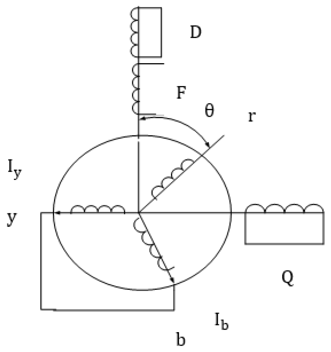
The general voltage equation for the machine in Figure 2 represented with the suffixes one and two referring to the field and armature system can be written as follow:
Convert the actual 3- phase to equivalent 2- phase system using
The transformed impedance matrix becomes
Figure 2.
Line to line short circuit current of three phase synchronous machine.
2.2.1. Field System Transformation
The field system transformation is applied to convert the machine equations from the natural reference frame into a more convenient form, usually the direct–quadrature (d–q) reference frame. This transformation simplifies the representation of the machine by aligning one axis with the rotor field, making the analysis of mutual inductances and flux linkages more straightforward. As a result, the coupling between the field winding and the armature windings can be expressed in terms of constant parameters, which greatly reduces the mathematical complexity of transient fault analysis [20].
Already in D-Q axis.
2.2.2. Armature/Field Inductance
The armature/field inductance represents the magnetic coupling between the stator (armature) and rotor (field) windings. Since the rotor rotates with respect to the stator, this mutual inductance varies with the rotor position and can be expressed as a trigonometric function of the rotor angle. This time-varying inductance is the main source of interaction between the armature and field circuits. During disturbances such as short circuits, the mutual inductance plays a critical role in transferring energy between the two systems, thereby influencing the transient current response and the stability of the synchronous machine [21].
2.2.3. Field/Armature Inductance
The field/armature inductance describes the magnetic coupling between the rotor (field) winding and the stator (armature) windings. This mutual inductance depends on the rotor position and is typically represented as a trigonometric function of the rotor angle. It is a key parameter in modeling synchronous machines because it governs how energy is transferred between the field and armature circuits. During fault conditions, such as a line-to-line short circuit, this inductive coupling significantly affects the magnitude and dynamics of the transient currents [22].
2.2.4. Armature/Armature Inductance
The armature/armature inductance represents the self-inductances of the stator windings as well as the mutual inductances between different stator phases. It includes the effects of saliency, i.e., differences between the direct (d) and quadrature (q) axis inductances, which influence the fault response. Accurate modeling of armature/armature inductance is essential for predicting the transient current distribution during short circuits, as it determines how currents in one phase affect the others [23].
Since:
By considering saliency effect and neglect harmonic component.
By omitting the red phase and connecting the yellow and blue windings together to be as a single-phase rotor and then we can deal with it like a single-phase machine [24]. System equation will be as follows:
Since generator mode
Substitute equation
2.2.5. Eliminate Damper
Damper windings are included in synchronous machines to reduce oscillations and improve stability. However, for simplified fault analysis, it is often convenient to eliminate damper currents from the system equations. This is done using matrix reduction techniques, which remove the damper variables while preserving the essential dynamics of the field and armature currents. The omission of the damper winding from the machine model leads to a significant simplification of the governing differential equations, thereby enabling a more tractable and analytically transparent formulation of the system. By reducing the number of coupled electrical circuits and associated state variables, the resulting model becomes more suitable for examining the fundamental aspects of the transient response under short-circuit conditions [25].
This assumption is particularly useful in the early stages of analysis, where the primary objective is to capture the dominant electromagnetic dynamics without the added complexity introduced by secondary damping effects. Although the damper winding contributes to the attenuation of oscillations and influences subtransient behavior, its exclusion does not substantially affect the overall accuracy of the model in representing the main transient characteristics. Consequently, this simplification provides an effective balance between mathematical manageability and fidelity in describing the essential short-circuit phenomena [26].
The Q axis is the damper will be eliminated first
Can also eliminate D axis
After eliminating the damper currents, the result system equation is:
This equation may be written in matrix form
So, the differential currents given by:
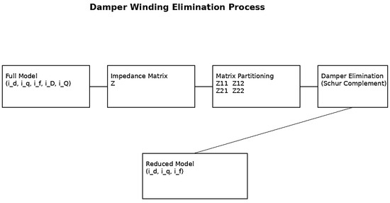
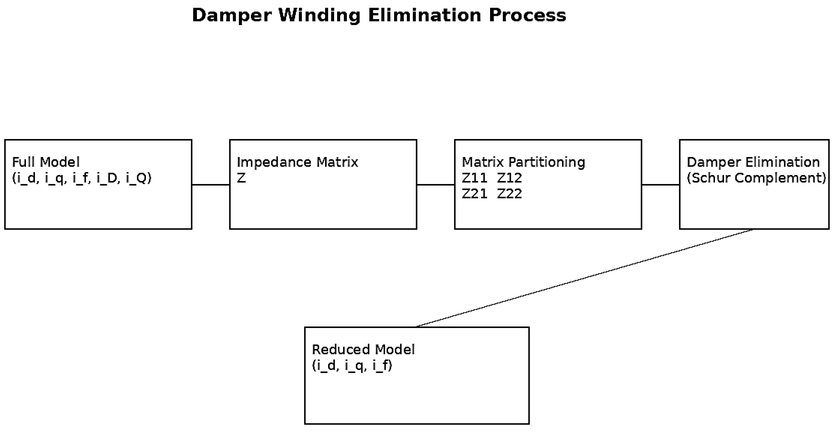
To improve the clarity of the damper winding elimination process, a schematic representation is presented in Figure 3. The diagram clearly illustrates the transformation from the full-order synchronous machine model, including damper windings, to a reduced-order system [27].
Figure 3.
Schematic diagram of the damper winding elimination process, showing the transition from the full synchronous machine model to the reduced-order model using matrix partitioning and Schur complement.
The procedure is based on impedance matrix formulation, followed by matrix partitioning and elimination of damper variables using the Schur complement. This approach simplifies the system while preserving the dominant transient dynamics of the machine.
By omitting the red phase and connecting the yellow and blue windings together to be as a single-phase rotor and then we can deal with it like a single-phase machine. System equation will be as follows [28]:
The elimination of damper winding currents is based on the assumption that their electrical time constants are significantly smaller than those of the field winding, allowing them to be approximated as quasi-steady-state variables. This enables the reduction of the system order through matrix partitioning and inversion techniques [29].
Specifically, the impedance matrix is partitioned into submatrices corresponding to retained and eliminated variables. By applying standard matrix reduction (Schur complement), the damper currents are expressed as functions of the remaining state variables and substituted back into the system equations.
This simplification reduces computational complexity while preserving the dominant transient dynamics. However, it introduces limitations, as high-frequency damping effects and detailed rotor transient interactions may not be fully captured. Therefore, the model is most accurate for short-circuit studies focused on fundamental-frequency transient behavior [19].
3. Numerical Integration Approach
To study the transient behavior of synchronous machines during short circuits, the system of nonlinear differential equations derived from the voltage and flux linkage relationships must be solved. These equations are typically coupled and time-varying, due to the rotor position-dependent mutual inductances and the interaction between the field and armature circuits. Analytical solutions are generally not feasible for such nonlinear systems, especially when considering realistic operating conditions and fault scenarios.
The fourth-order Runge-Kutta (RK4) method is widely used for solving these equations numerically. RK4 provides a good balance between computational accuracy and efficiency, making it suitable for time-domain simulations of short-circuit events. The method works by computing an intermediate set of slope estimates at each integration step, which are then combined to calculate the next value of the state variable. For the synchronous machine, the state variables are primarily the field and armature currents.
The RK4 procedure involves the following steps:
- Evaluate derivatives at the initial point: Compute the derivatives of the currents using the system equations at the current time step.
- Estimate slopes at intermediate points: Calculate slopes at several points within the time step using a weighted average approach. These intermediate slopes account for the nonlinear coupling between field and armature circuits.
- Update state variables: Combine the slopes to advance the solution to the next time step, ensuring fourth-order accuracy.
- Iterate over the simulation period: Repeat the process for all time steps to generate the complete transient response.
This method is particularly effective for simulating large transient currents and oscillatory behavior during faults. By using sufficiently small-time steps, RK4 can accurately capture the fast dynamics of electromechanical interactions and electromagnetic torque oscillations. Additionally, it allows the study of various system parameters, such as resistance, inductance, and rotor speed, on the transient response.
The RK4 method provides a robust numerical tool for analyzing synchronous machine dynamics under short-circuit conditions, enabling researchers to predict current waveforms, evaluate machine stresses, and design protective measures for both single-phase and three-phase machines.
To ensure reproducibility and numerical stability of the simulations, specific implementation details of the Runge–Kutta fourth-order (RK4) method were defined. A fixed time step of Δt = 1 × 10⁻⁵ s was selected after preliminary convergence testing, ensuring accurate resolution of fast transient phenomena without excessive computational cost. The convergence of the numerical solution was verified by comparing results obtained with smaller step sizes (Δt = 5 × 10⁻⁶ s), which showed negligible deviation (<1% in peak current values) [30].
The MATLAB/SIMULINK model was implemented using a variable-step solver (ode45) for validation purposes, while the primary simulations were conducted using a fixed-step discrete solver to ensure consistency with the RK4 implementation. The solver configuration included automatic step-size control with a maximum step size constraint equal to the RK4 time step.
The system of differential equations was implemented in both MATLAB/SIMULINK and a FORTRAN-based numerical solver, ensuring cross-validation of results. The agreement between the two implementations confirms the numerical robustness of the adopted solution approach.
4. Simulation and Results
A detailed MATLAB/SIMULINK model of both single-phase and three-phase synchronous machines is developed. The model includes:
- Machine parameters (resistance, leakage inductance, mutual inductance).
- Field and damper windings.
- Fault implementation modules (single-phase short circuit, line-to-line short circuit).
- Measurement blocks for current and voltage.
- Oscillographs of transient currents are obtained for various initial rotor positions, demonstrating the dependence of response on machine operating point, the main parameters that used in simulations as shown in Table 1.Table 1. Machine parameters.
4.1. Single-Phase Machine Short Circuit
The transient response shows an immediate high peak of current followed by damped oscillations. The waveform magnitude and shape depend strongly on the rotor angle at fault initiation. For some rotor positions, the transient current magnitude doubles compared to others. Theoretical calculations based on leakage inductance and rotor angle match the simulated waveforms [31].
Now we show the stator and rotor current wave at different angle between rotor and stator:
4.2. Using Fortran Program
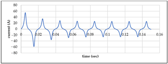
The Figure 4 shows the transient armature current of a single-phase synchronous machine during a sudden short circuit at θ0 = 0, where a large initial negative peak is followed by damped oscillations that gradually settle into a steady periodic response.
Figure 4.
Single phase seen/Mc short circuit armature current response at Θ0 = 0.
The Figure 5 shows the field current response of a single-phase synchronous machine during a sudden short circuit at θ0 = 0, where the current initially rises sharply to a peak before decaying through damped oscillations to a steady periodic level.
Figure 5.
Single phase SYN/Mc short circuit field current response at Θ0 = 0.
The Figure 6 shows the armature current response of a single-phase synchronous machine during a sudden short circuit at θ0 = π/2, exhibiting an initial large positive peak followed by damped oscillations that gradually settle into a steady symmetrical waveform.
Figure 6.
Single phase SYN/Mc short circuit armature current response at Θ0 = π/2.
The Figure 7 shows the field current response of a single-phase synchronous machine during a sudden short circuit at θ0 = π/2, where the current exhibits an initial sharp rise followed by damped oscillations that gradually converge to a steady periodic pattern.
Figure 7.
Single phase SYN/Mc short circuit field current response at Θ0 = π/2.
The Figure 8 shows the armature current response of a single-phase synchronous machine during a sudden short circuit at θ0 = π, where the current reaches a large initial positive peak followed by decaying oscillations that gradually settle into a stable periodic waveform.
Figure 8.
Single phase SYN/Mc short circuit armature current response at Θ0 =π.
The Figure 9 shows the field current response of a single-phase synchronous machine during a sudden short circuit at θ0 = π, where the current initially rises sharply to a peak and then decays through damped oscillations toward a steady periodic level.
Figure 9.
Single phase SYN/Mc short circuit field current response at Θ0 = π.
The Figure 10 shows the armature current response of a single-phase synchronous machine during a sudden short circuit at θ0 = 3π/2, exhibiting a large initial positive and negative swing followed by damped oscillations that gradually settle into a steady symmetrical waveform.
Figure 10.
Single phase SYN/Mc short circuit armature current response Θ0 = 3π/2.
The Figure 11 shows the field current response of a single-phase synchronous machine during a sudden short circuit at θ0 = 3π/2, where the current initially peaks sharply and then decays through damped oscillations toward a stable periodic waveform.
Figure 11.
Single phase SYN/Mc short circuit field current response Θ0 = 3π/2.
Using MATLAB SIMULINK
Figure 12.
Single phase seen/Mc short circuit current response at Θ0 = 0.
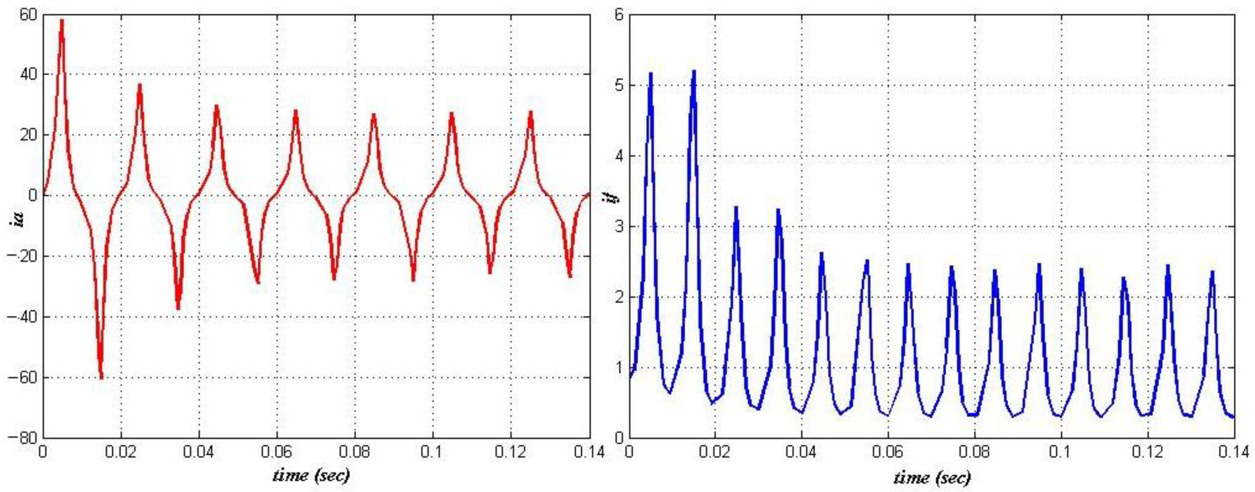
Armature current (Ia): Both show a large initial negative dip followed by periodic, damped pulsations converging to a similar steady envelope; SIMULINK is slightly smoother with marginally smaller/deeper early peaks—differences consistent with solver/step-size and interpolation effects.
Field current (If): Both exhibit a sharp first spike and a rapidly decaying series of pulses toward the same periodic level; peak magnitudes and timing align closely.
Overall, the SIMULINK results closely reproduce the FORTRAN transients (shape, frequency, decay), with only minor amplitude/phase deviations attributable to numerical settings—supporting the correctness of both implementations.
To provide a quantitative assessment of the agreement between SIMULINK and FORTRAN results, key performance indicators were evaluated. The peak armature current deviation between the two methods was found to be below 2.5%, while the oscillation decay time constants differed by less than 3%.
Additionally, the root means square error (RMSE) between the current waveforms over the first 0.1 s of the transient was calculated, confirming a high level of numerical consistency. These results demonstrate that both implementations provide equivalent accuracy for transient short-circuit analysis [32].
Figure 13 shows the single-phase synchronous machine short-circuit current response at θ0 = π/2 obtained using MATLAB/SIMULINK. The armature current exhibits an initial large positive peak followed by damped oscillations, while the field current displays a sharp rise and gradually decaying pulsations. The results closely match the FORTRAN plots (Figure 5 and Figure 6) in waveform shape, frequency, and decay trend, confirming consistent transient behavior and validating the accuracy of both simulation methods.
Figure 13.
Single phase SYN/Mc short circuit current response at Θ0 = π/2.
Figure 14 shows the single-phase synchronous machine short-circuit current response at θ0 = π obtained using MATLAB/SIMULINK. The armature current exhibits a large initial positive peak followed by damped oscillations, while the field current displays a sharp first rise and gradually decaying periodic pulses. These results are in excellent agreement with the FORTRAN outputs (Figure 7 and Figure 8), showing nearly identical transient shapes, amplitudes, and decay characteristics—confirming the reliability and consistency of both numerical approaches.
Figure 14.
Single phase SYN/Mc short circuit current response at Θ0 = π.
Figure 15 shows the single-phase synchronous machine short-circuit current response at θ0 = 3π/2 using MATLAB/SIMULINK. The armature current displays alternating large positive and negative peaks that decay over time, while the field current exhibits damped oscillations converging to a steady periodic waveform. The results closely correspond to the FORTRAN plots (Figure 10 and Figure 11), confirming consistent transient characteristics and validating the numerical accuracy of both simulation methods. The transient response of a synchronous machine under sudden short-circuit conditions is strongly dependent on the initial rotor angle at the instant the fault occurs. Variations in rotor position lead to different electromagnetic coupling conditions between the rotor and stator, resulting in distinct distributions of currents in both circuits. These differences arise from the interaction between the main magnetic flux and the associated leakage flux paths, which are inherently position-dependent.
Figure 15.
Single phase SYN/Mc short circuit armature response Θ0 = 3π/2.
Consequently, the amplitude, phase, and temporal evolution of the transient currents are directly influenced by the rotor’s initial angular displacement, affecting the overall dynamic behavior of the machine during the fault.
The key observations are as follows:
- 1-
- Rotor Angle δ = π/2 and 3π/2:
The rotor current rises sharply because the rotor’s leakage flux is forced into alternative paths, primarily inside the stator bore.
To maintain its original flux linkage, the stator current increases to high values.
This behavior indicates a strong electromagnetic coupling between rotor and stator, where the stator attempts to preserve flux despite the sudden short circuit.
- 2-
- Rotor Angle δ = 0 and π:
At these angles, the stator initially has zero flux linkage. As a result, the stator current drops to nearly zero.
Meanwhile, the rotor current returns to normal values since the leakage flux is not significantly disturbed.
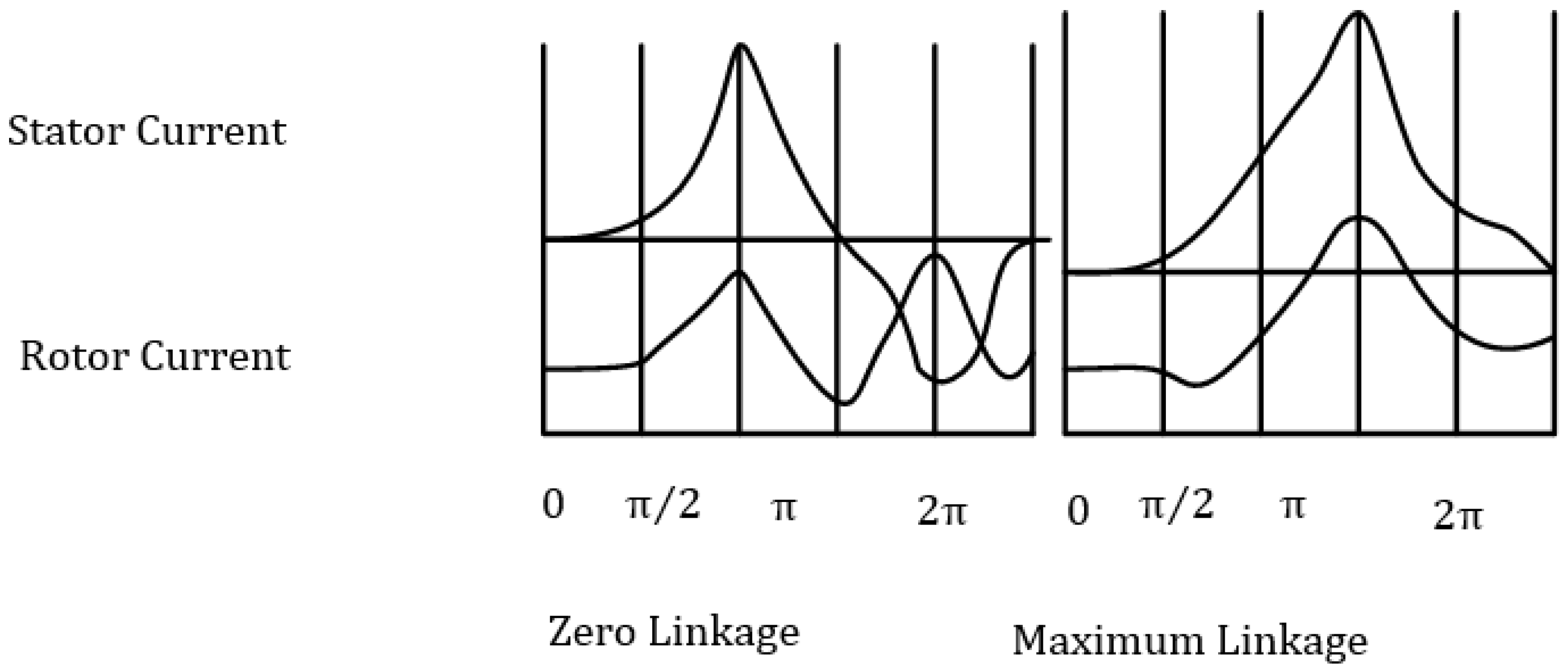
These behaviors can be visualized using Figure 16, which illustrates the constant flux linkage during a single-phase short circuit. The results demonstrate that the magnitude and timing of transient currents depend strongly on the rotor’s instantaneous position, which affects how flux is distributed between the rotor and
The above result can be represented by using figure bellow:
Figure 16.
Constant linkage single phase short circuit.
Three-Phase Machine Short Circuit with Damper Windings
The inclusion of damper windings introduces additional damping, reducing oscillation amplitudes compared to the single-phase case. The short circuit currents exhibit a rapid initial surge, followed by oscillations with faster decay. SIMULINK waveforms validate numerical integration results, demonstrating consistency across analytical and simulation methods.
Now we show the stator and rotor current wave at different angle between rotor and stator.
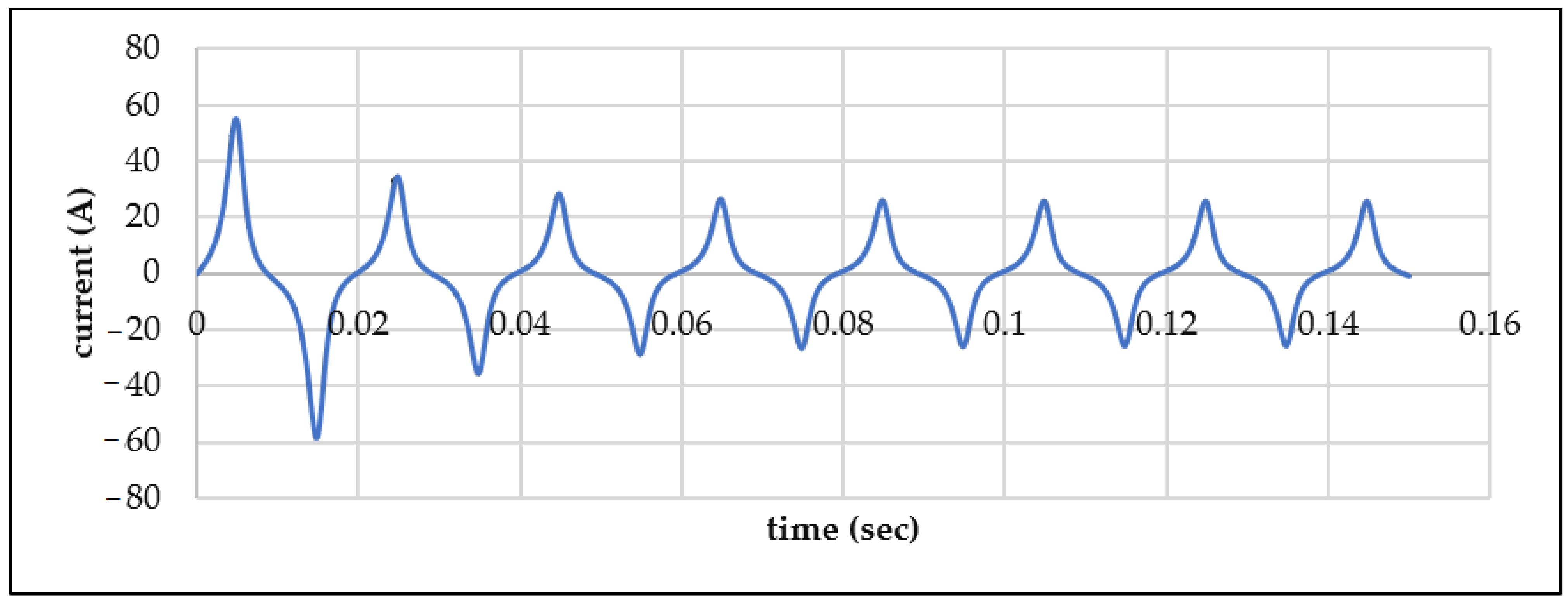
Figure 17 represent the line-to-line short circuit at θ0 = 0, the armature current exhibits a strong negative DC offset and a rapidly decaying transient component, stabilizing within about 0.08 s into a steady 50 Hz sinusoidal waveform, reflecting effective damping and normal machine response.
Figure 17.
Three phase SYN/MC line to line short circuit armature current response at Θ0 = 0.
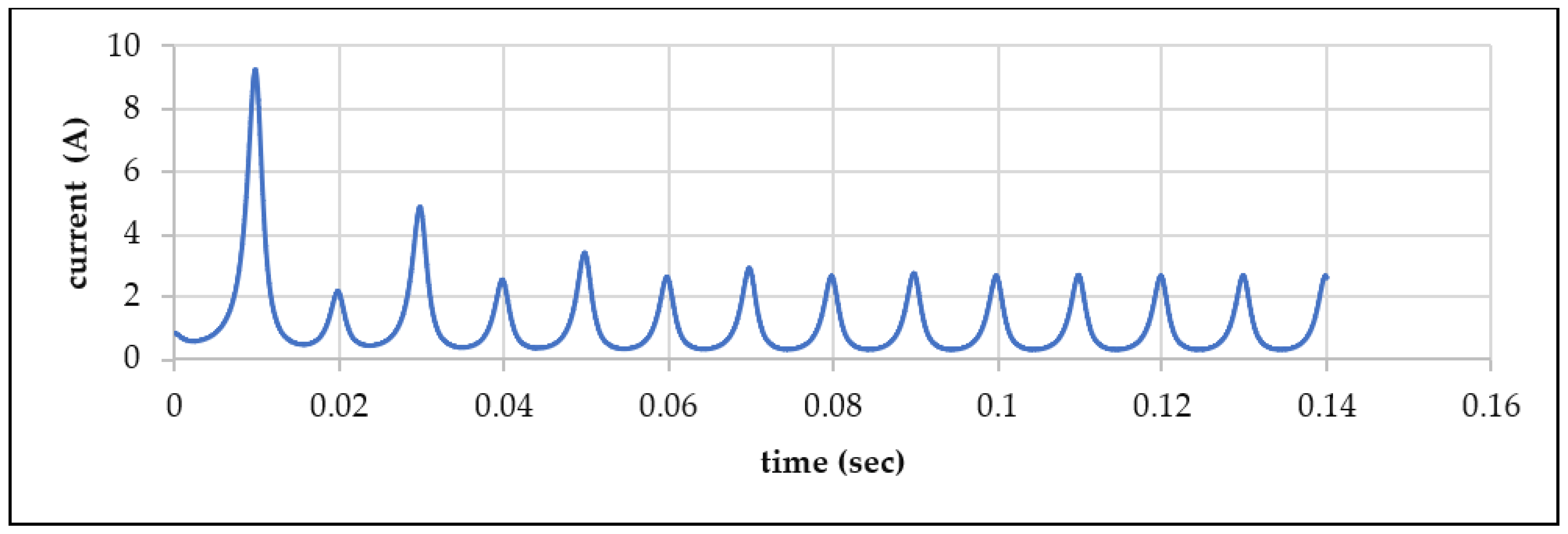
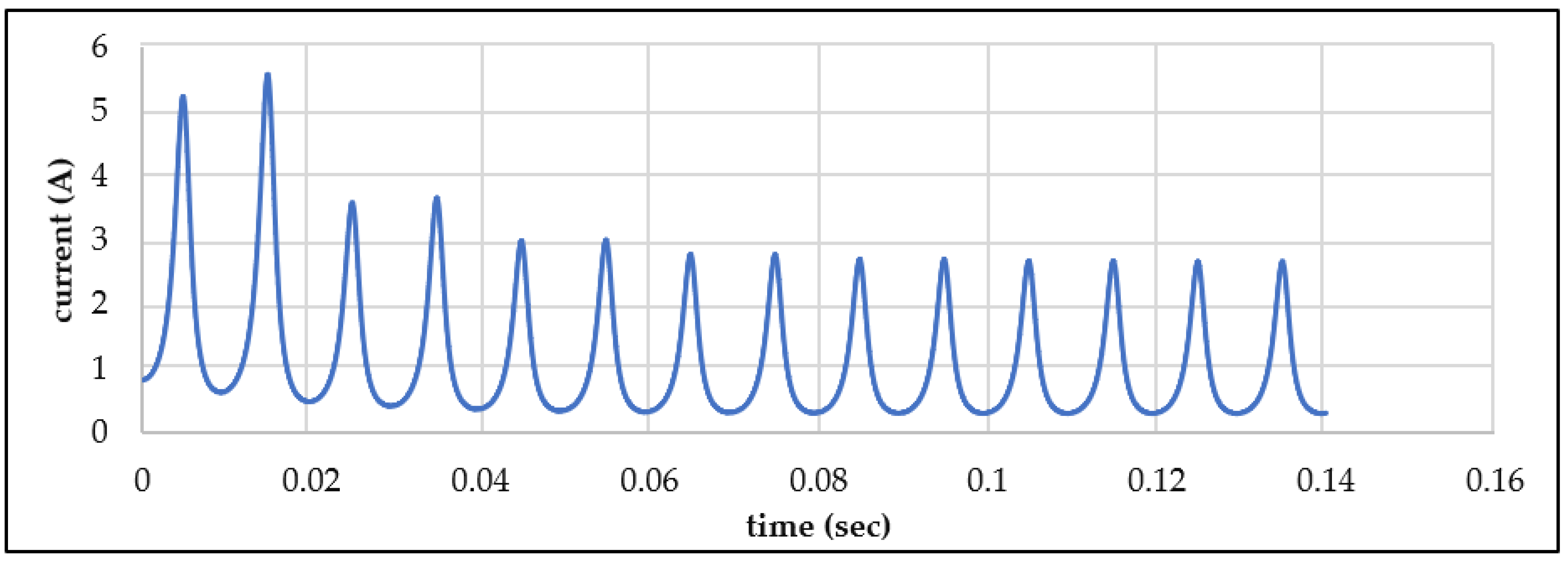
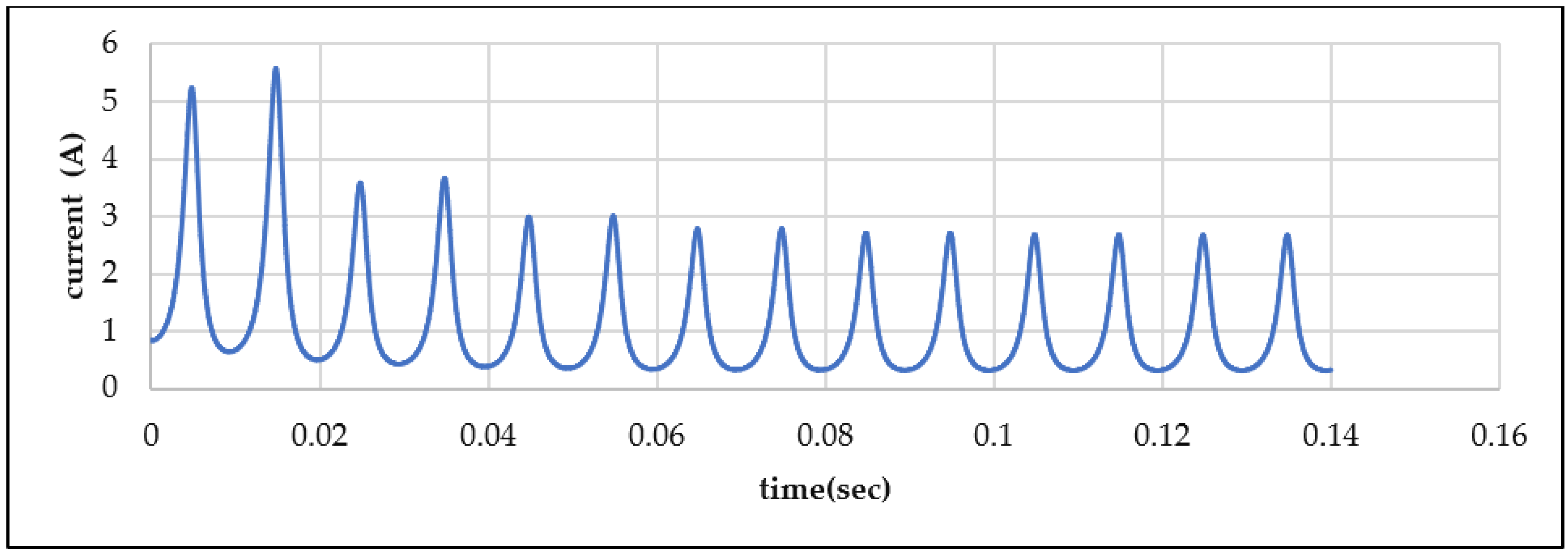
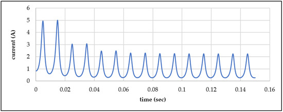
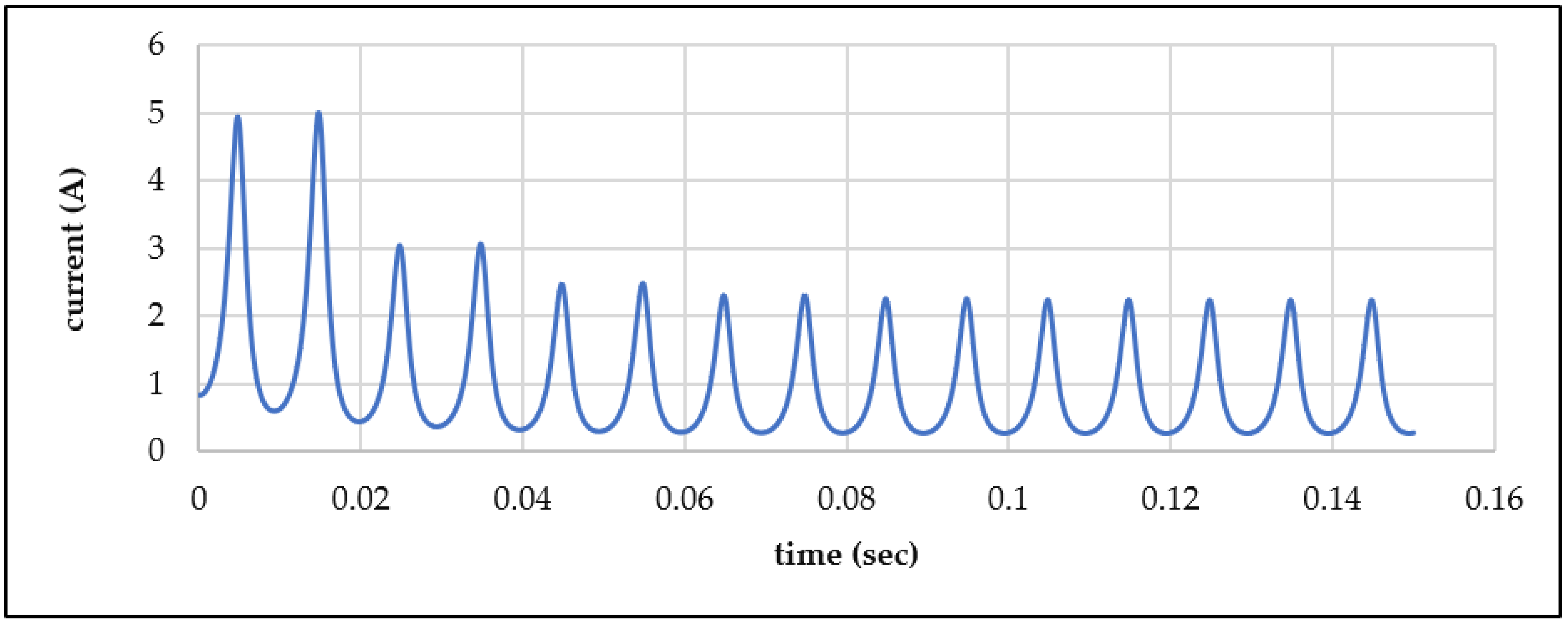
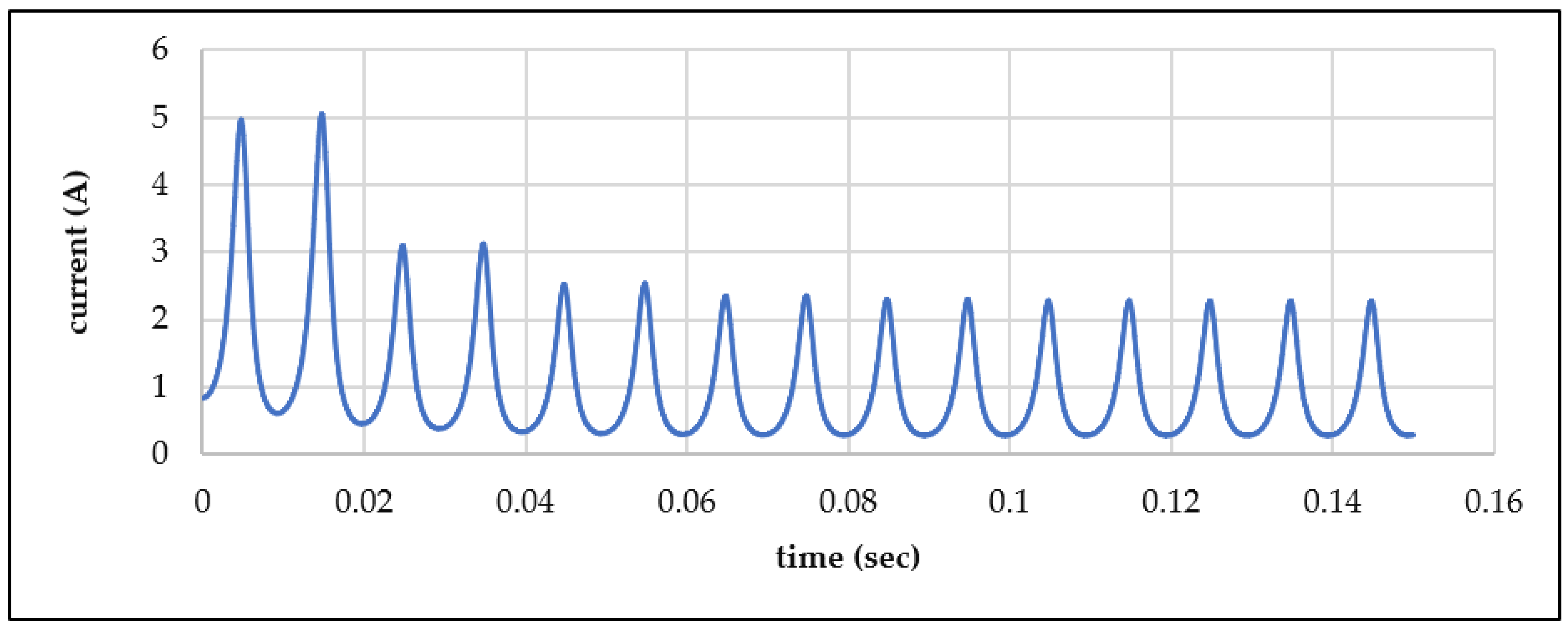
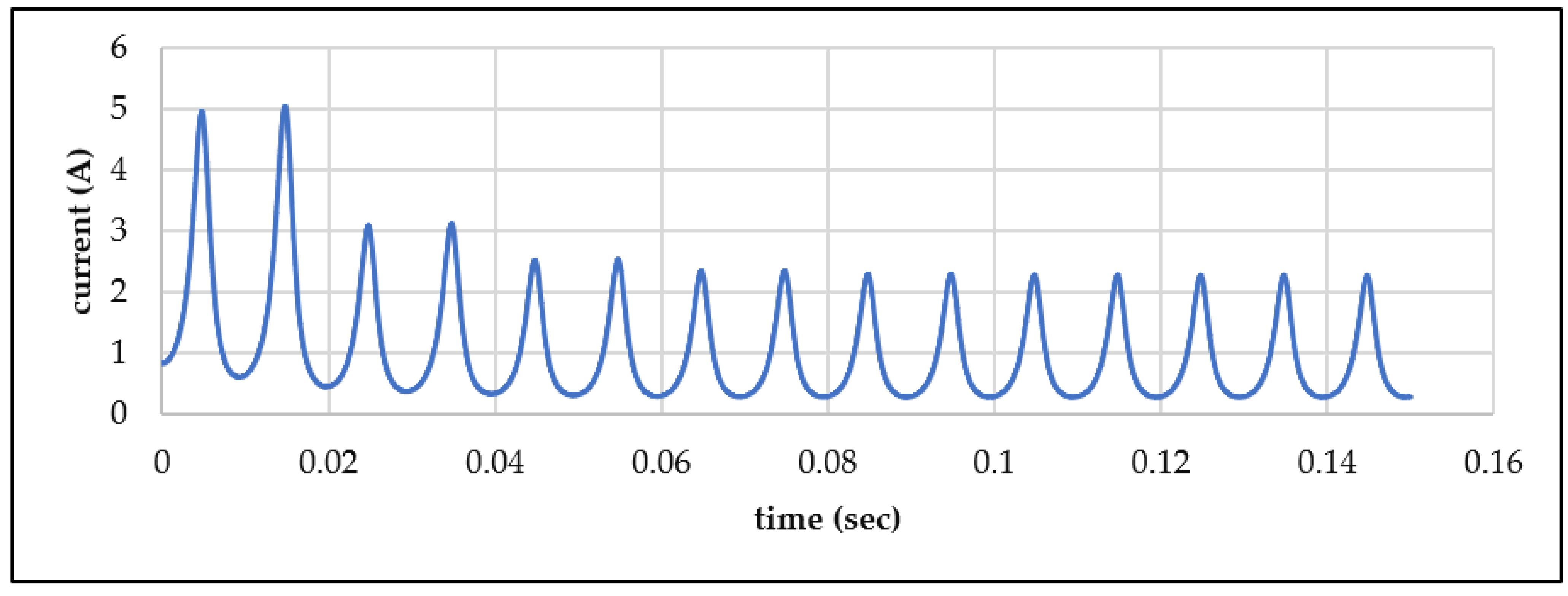
Figure 18 represent the line-to-line short circuit at θ0 = 0, the field current rises sharply to about 5 A immediately after the fault and then decays smoothly with oscillations toward a steady level, indicating strong electromagnetic coupling and effective damping of transient energy.
Figure 18.
Three phase SYN/MC line to line short circuit field current response at Θ0 = 0.
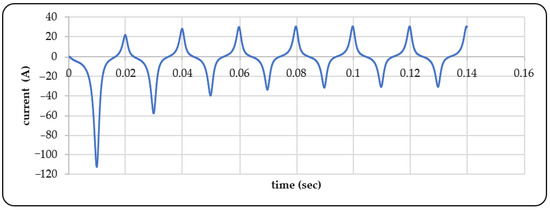
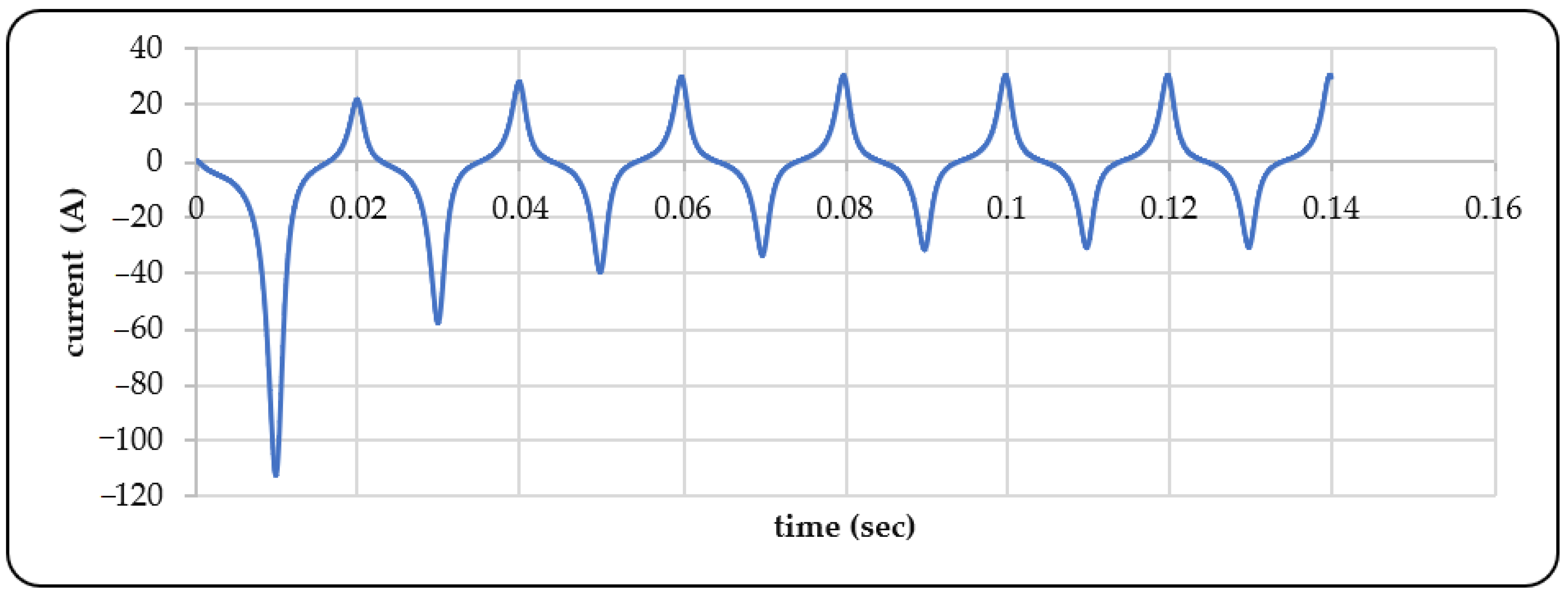
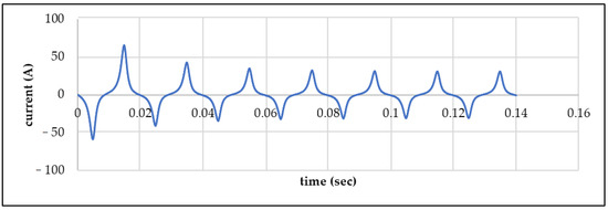
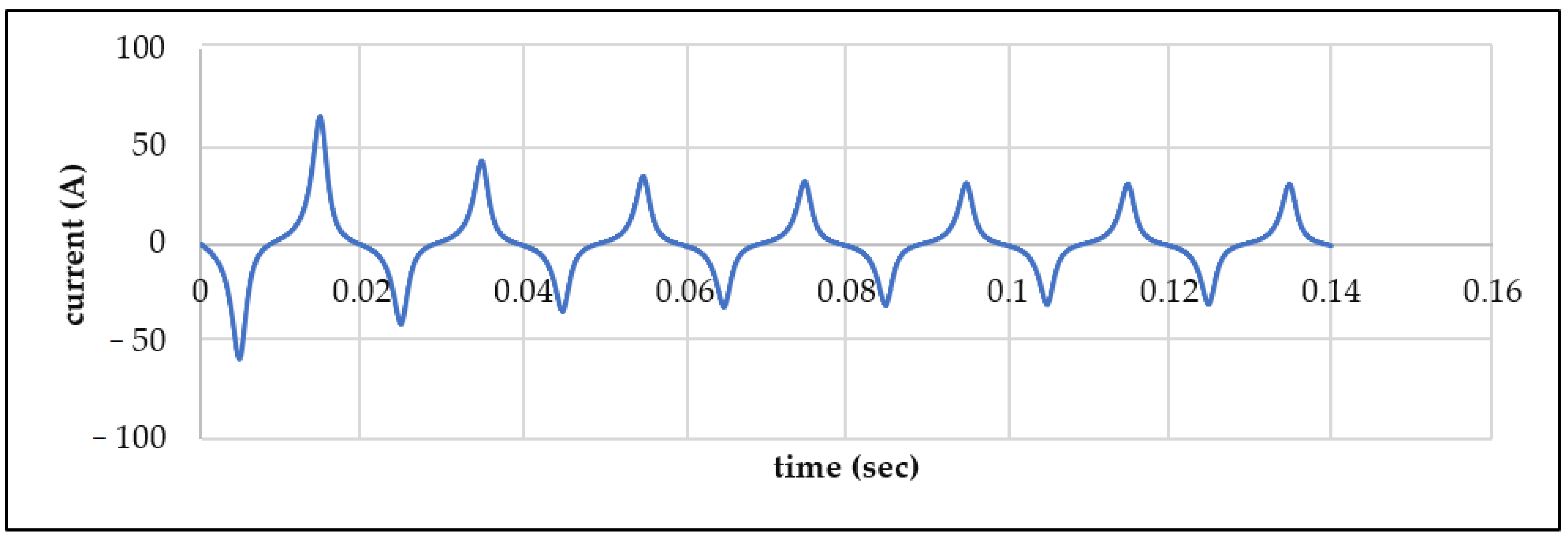
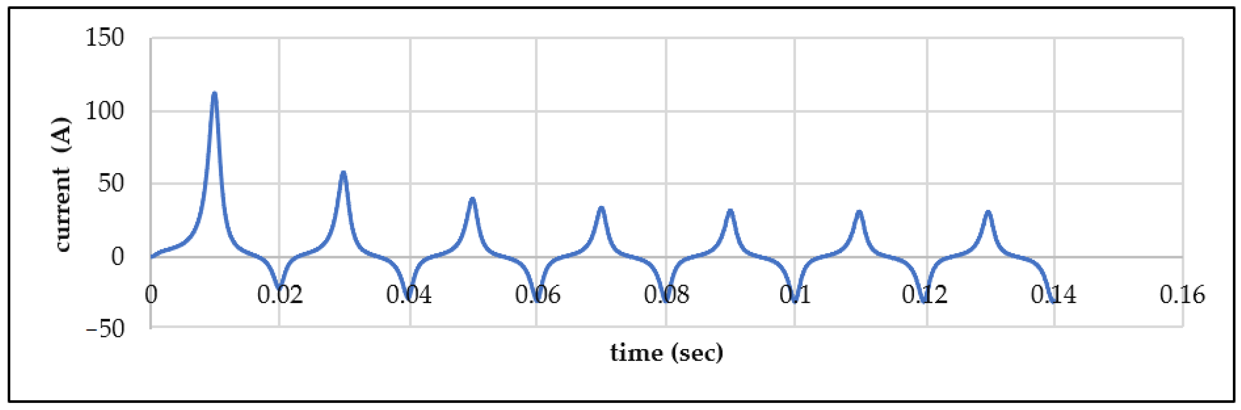
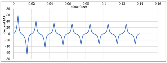
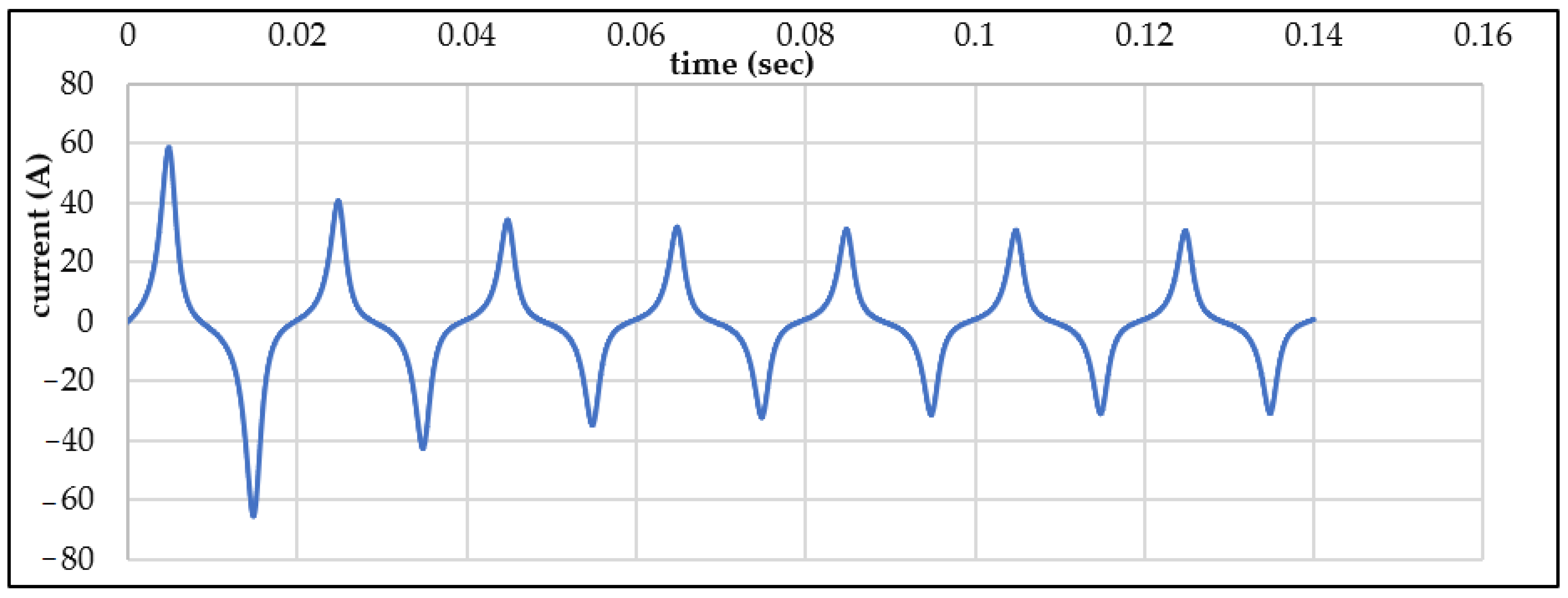
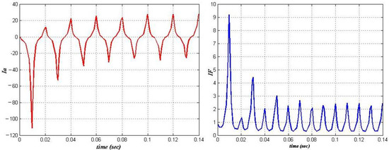
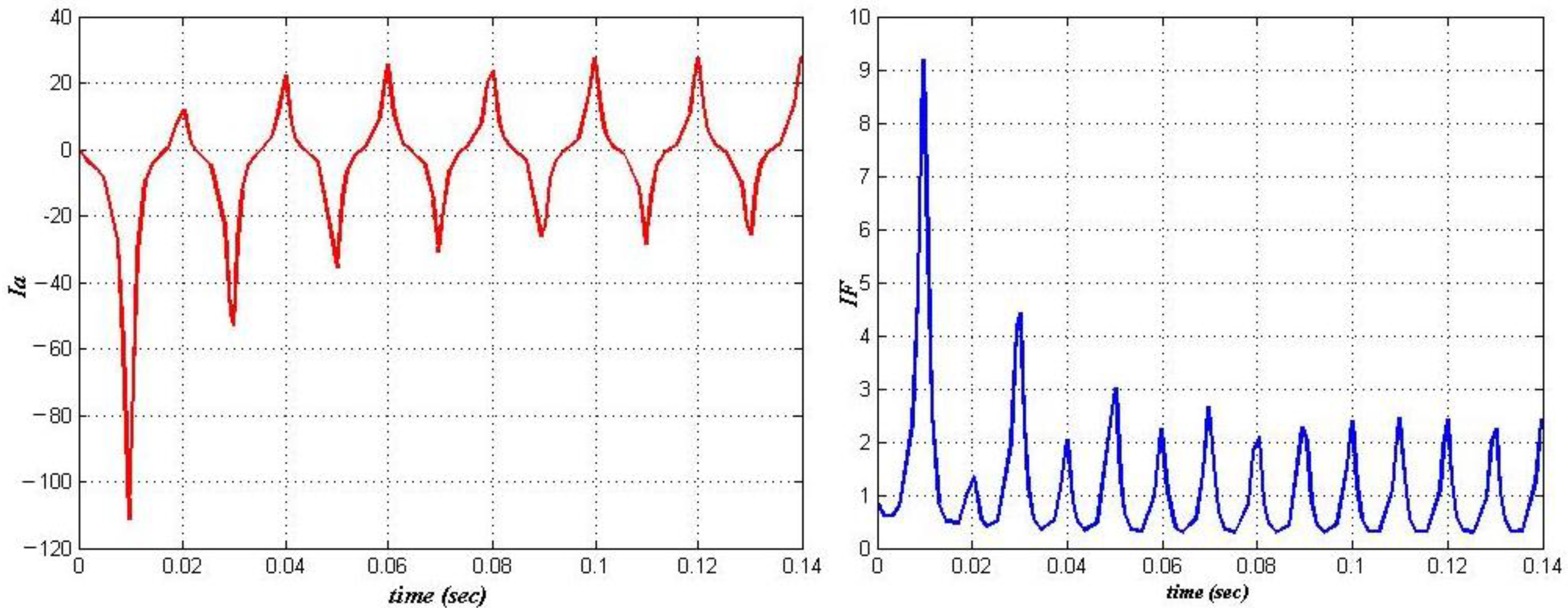
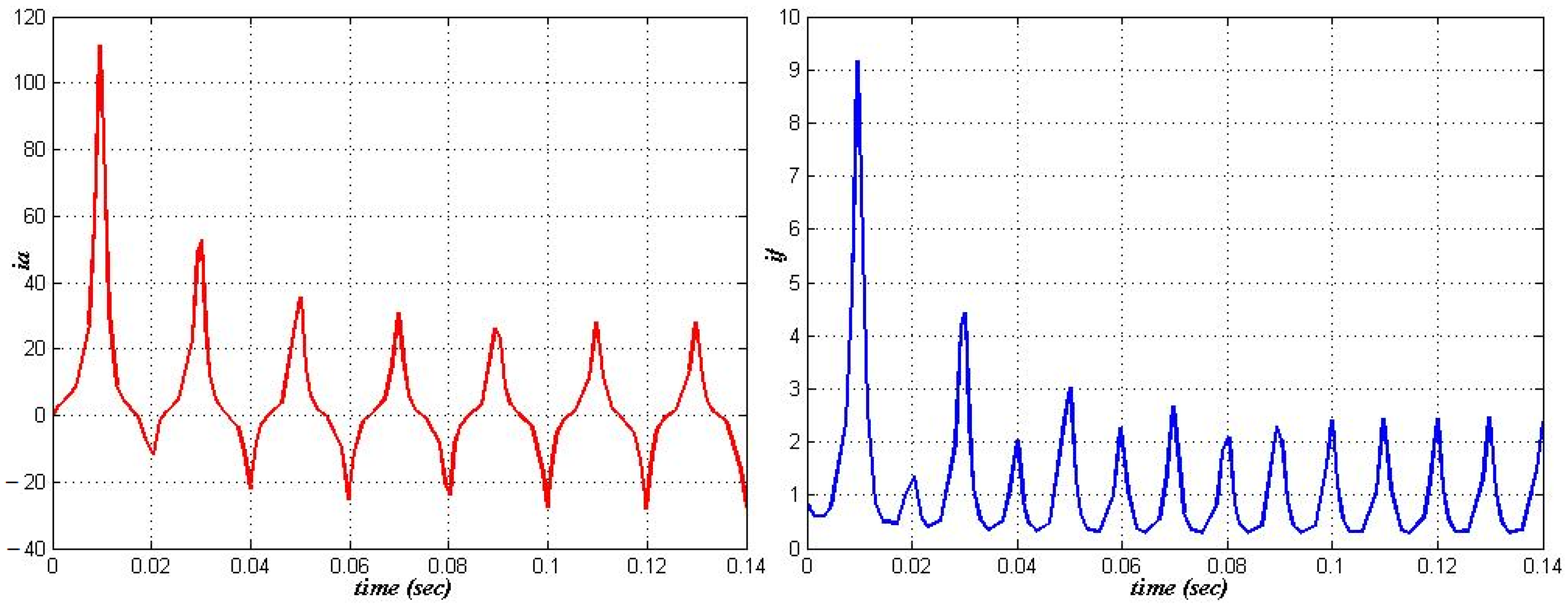
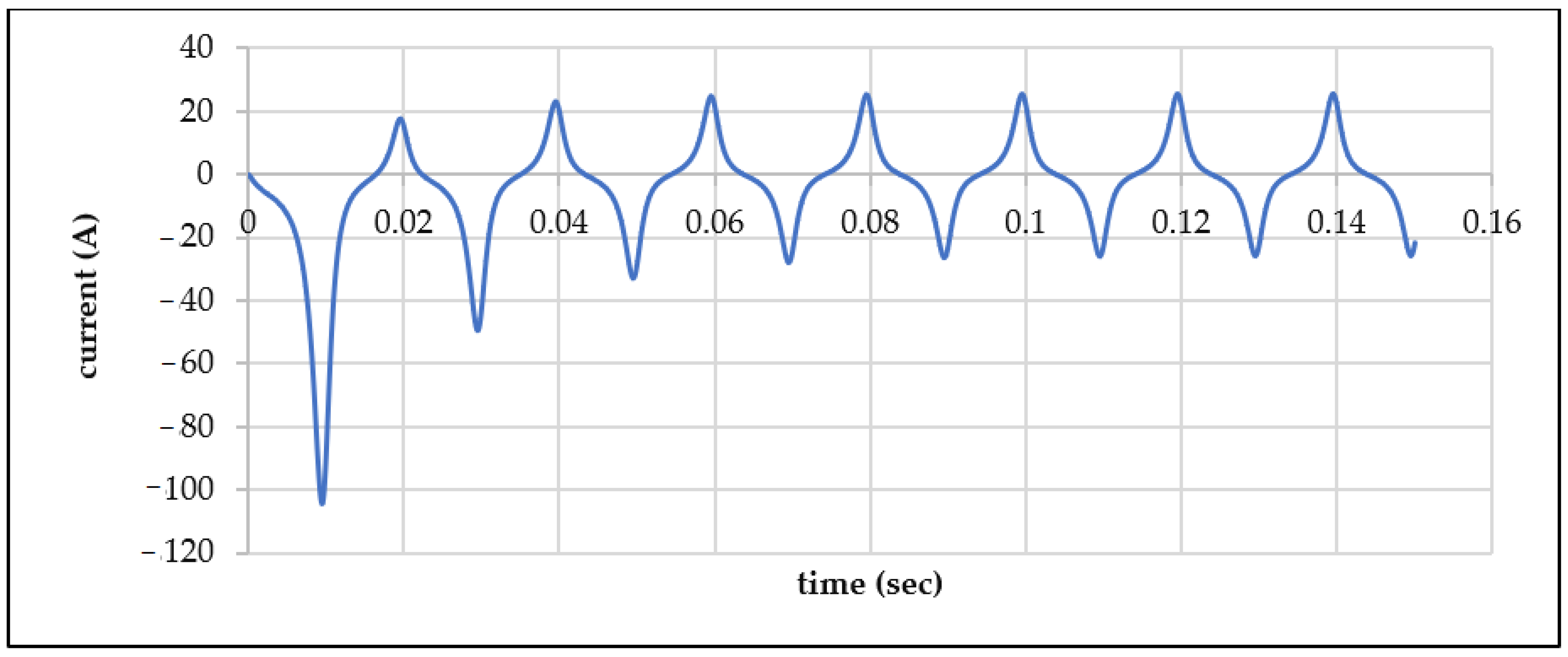
Figure 19 represent the line-to-line short circuit at θ0 = π/2, the armature current shows a large negative initial peak near −100 A followed by alternating positive peaks around 20 A, indicating a dominant DC offset with polarity reversal from θ0 = 0 and a gradually decaying transient toward steady-state oscillations.
Figure 19.
Three phase SYN/MC line to line short circuit armature current response at Θ0 = π/2.
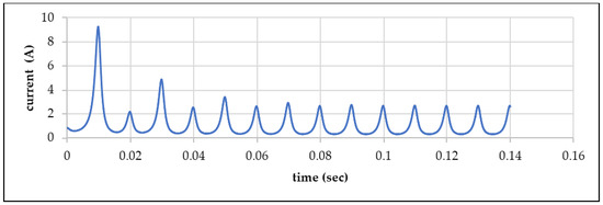
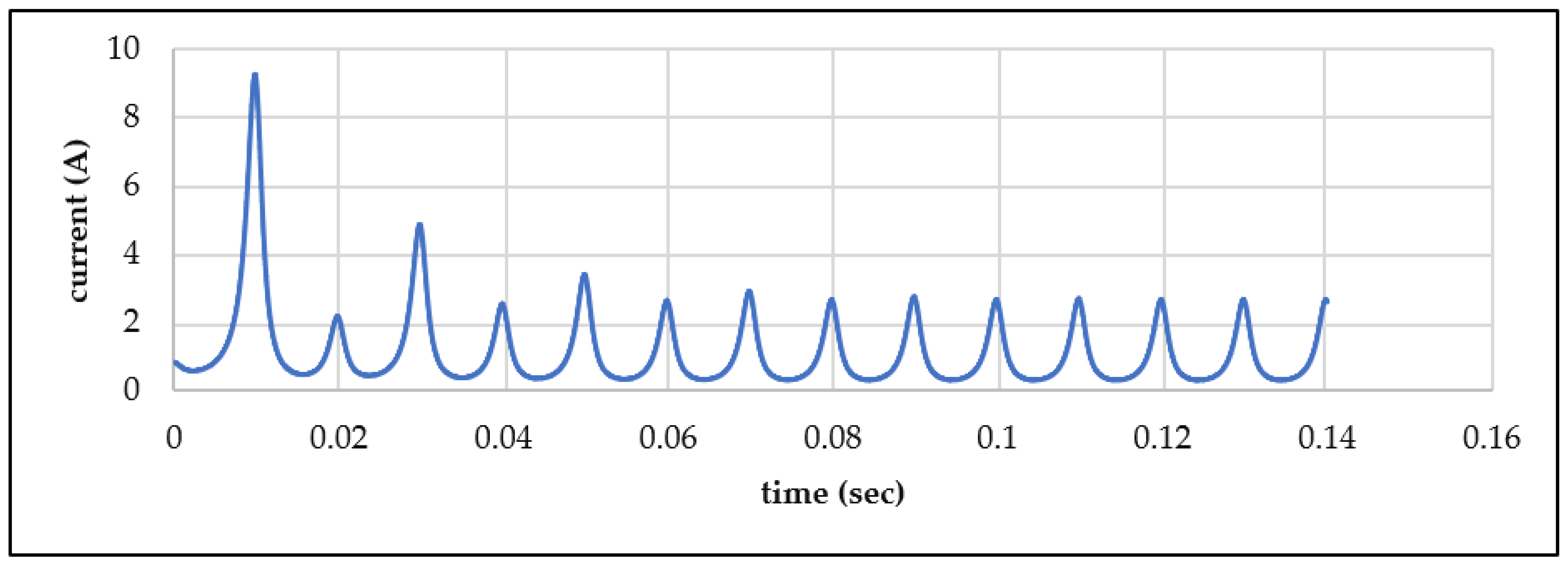
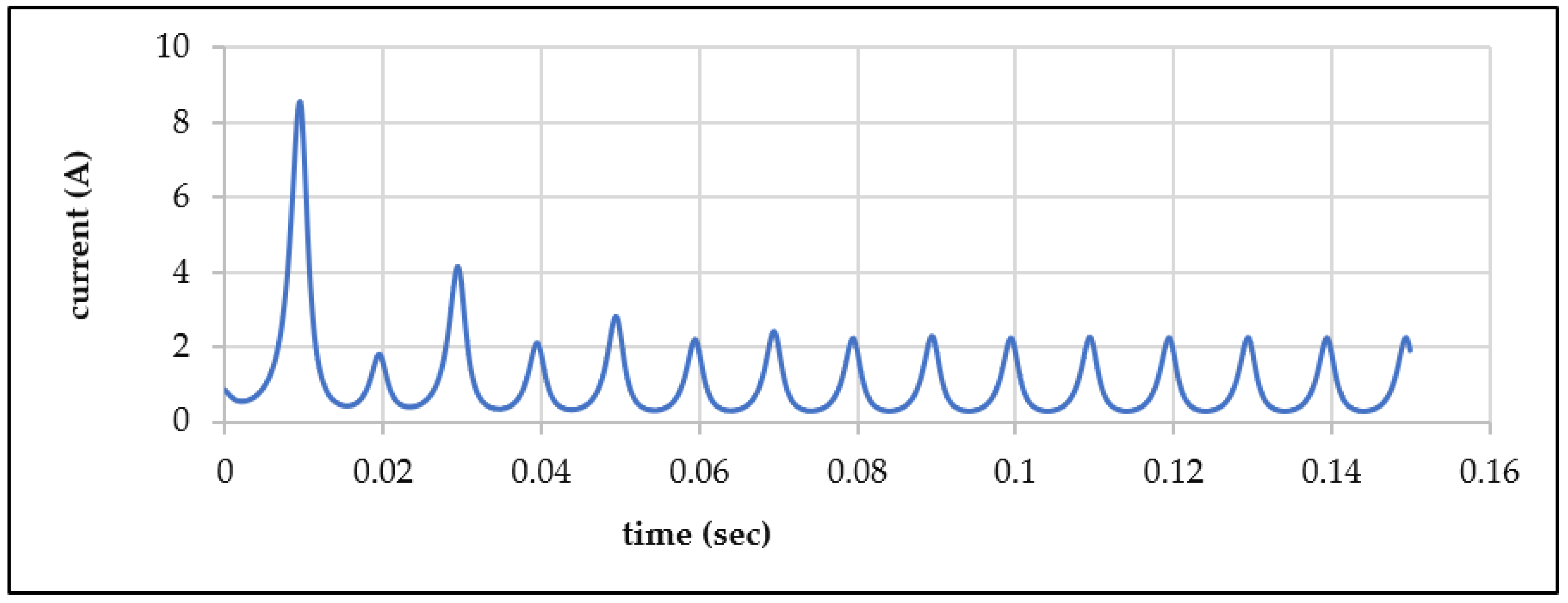
Figure 20 represent the line-to-line short circuit at θ0 = π/2, the field current experiences a sharp rise to about 9 A followed by a smooth exponential decay with small oscillations, showing stronger initial coupling and higher transient energy than the θ0 = 0 case
Figure 20.
Three phase SYN/MC line to line short circuit field current response at Θ0 = π/2.
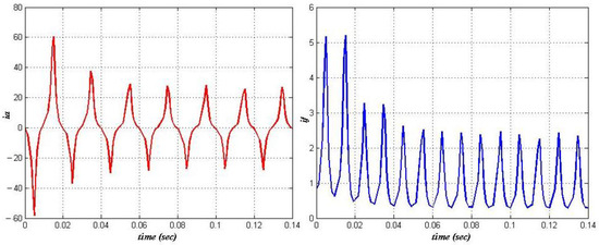
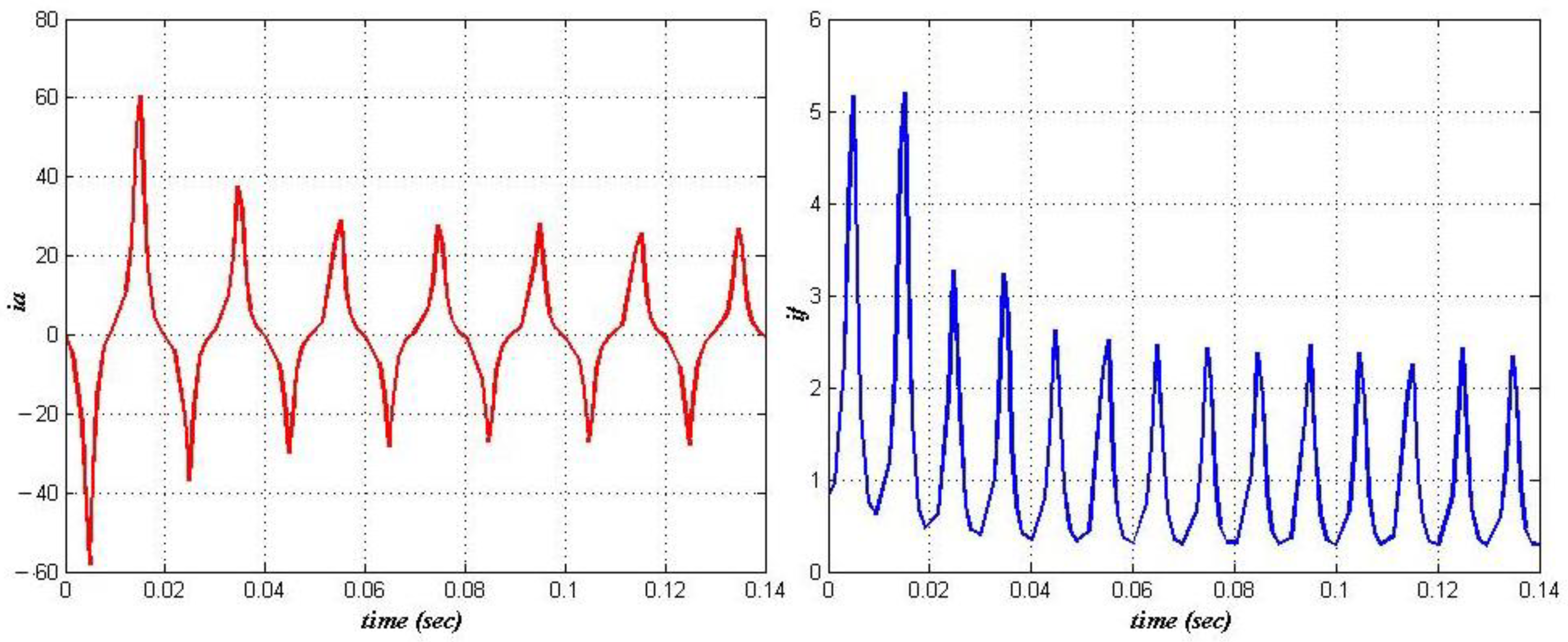
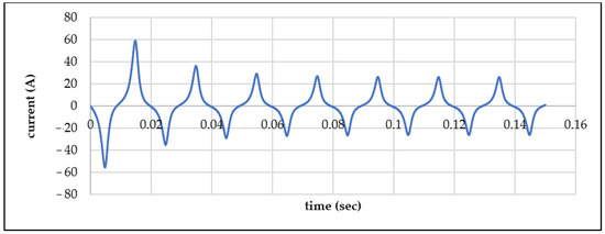
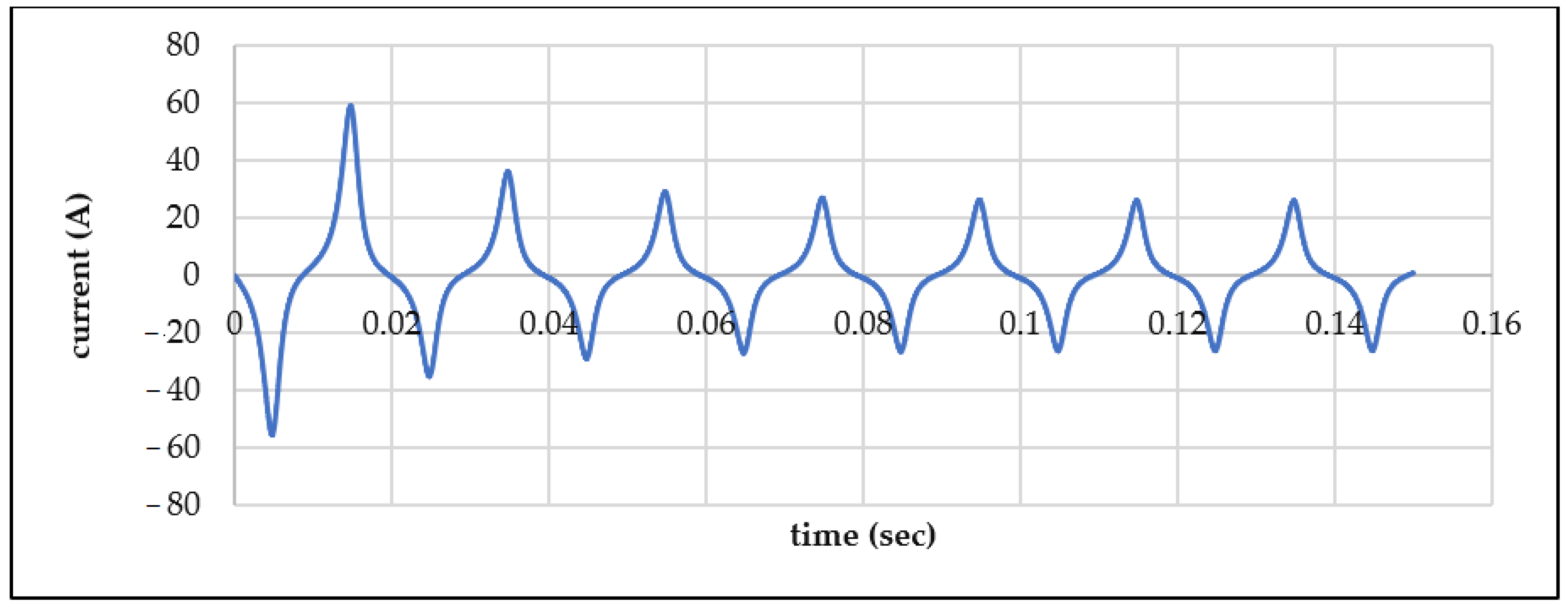
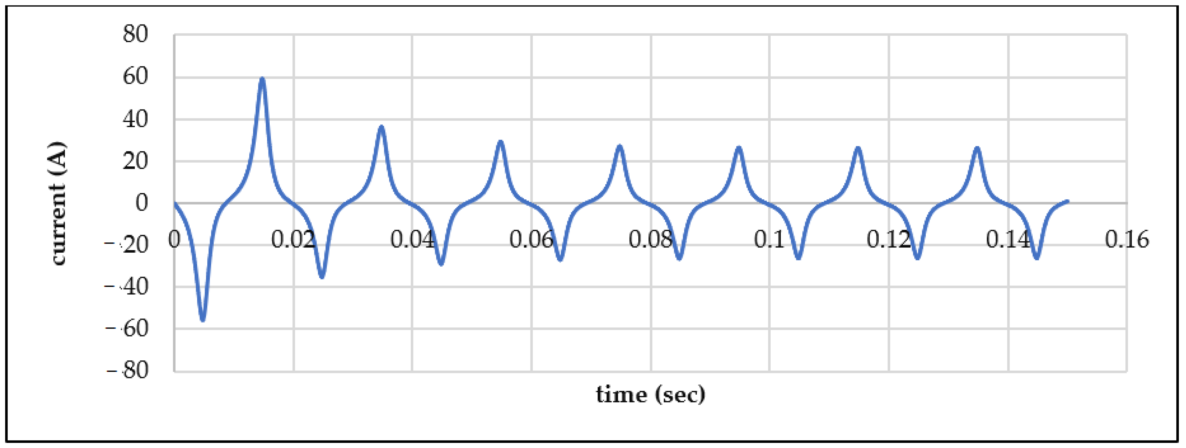
Figure 21 represent the line-to-line short circuit at θ0 = π, the armature current displays a strong positive DC offset with an initial peak around 60 A that decays steadily to a balanced 50 Hz waveform, indicating phase reversal relative to θ0 = 0 and stable transient damping.
Figure 21.
Three phase SYN/MC line to line short circuit armature current response at Θ0 = π.
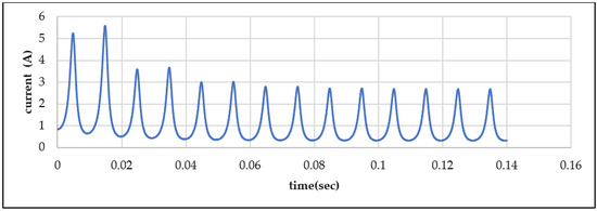
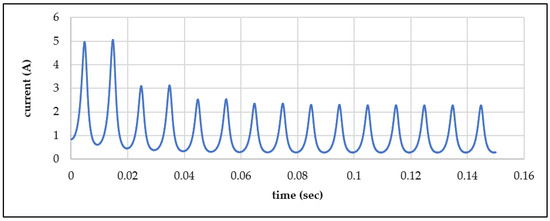
Figure 22 represent the line-to-line short circuit at θ0 = π, the field current shows a rapid rise to about 5 A followed by an exponential decay with periodic ripples, demonstrating strong electromagnetic coupling and symmetrical transient behavior like the θ0 = 0 case.
Figure 22.
Three phase SYN/MC line to line short circuit field current response at Θ0 = π.
Figure 23 represent the line-to-line short circuit at θ0 = 3π/2, the armature current exhibits a strong negative DC offset with an initial peak around −70 A that gradually decays to a steady 50 Hz waveform, indicating phase reversal and symmetrical transient behavior compared to θ0 = π.
Figure 23.
Three phase SYN/MC line to line short circuit armature current response at Θ0 = 3π/2.
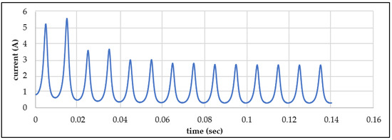
Figure 24 represent the line-to-line short circuit at θ0 = 3π/2, the field current rises rapidly to about 5 A and then decays exponentially with mild oscillations, indicating effective damping and transient behavior that mirrors the θ0 = π/2 case but with opposite polarity coupling.
Figure 24.
Three phase SYN/MC line to line short circuit field current response at Θ0 = 3π/2.
5. Discussion
The transient response of a synchronous machine during a short-circuit fault is strongly influenced by the initial rotor angle (δ) at the instant of fault. The rotor and stator currents behave differently depending on whether the rotor is at a maximum flux linkage position or at a zero-linkage position. The key observations are summarized as follows:
- Rotor Angle δ = π/2:
Rotor Current: The rotor current increases due to the maximum linkage position. The leakage flux is partially forced into the stator bore, resulting in a significant rise in rotor current.
Stator Current: The stator current also increases to maintain the original flux linkage of the machine, but its value remains lower than that observed in a single-phase short circuit.
- 2.
- Rotor Angle δ = 0, 3π/2:
Rotor Current: At δ = 0, the rotor is at a zero-linkage position, so the rotor current remains normal. At δ = 3π/2, the rotor current rises sharply because the leakage flux is forced into the stator bore.
Stator Current: At δ = 0, the stator has zero linkage and the current drops to zero. At δ = 3π/2, the stator current rises to high values to maintain flux linkage with the rotor.
- 3.
- Rotor Angle δ = π:
Rotor Current: The rotor current rises significantly as its leakage flux is directed into alternative paths, primarily inside the stator bore.
Stator Current: The stator current also increases to maintain its original flux linkage, reflecting the strong electromagnetic coupling between rotor and stator.
The rotor and stator currents are highly dependent on the instantaneous rotor position. Maximum flux linkage positions result in high transient currents in both rotor and stator, while zero linkage positions produce minimal stator current and normal rotor current. These observations highlight the importance of considering rotor angle and leakage paths when analyzing synchronous machine faults, particularly in single-phase and three-phase short-circuit scenarios.
From an engineering perspective, the strong dependence of short-circuit current magnitude on rotor angle has important implications for protection system design. Protective relays must be capable of detecting fault currents under varying initial conditions, including worst-case peak scenarios associated with specific rotor positions.
Furthermore, the observed influence of leakage inductance and damper windings on transient decay rates can inform machine design optimization, particularly in improving fault withstand capability and reducing mechanical stress during disturbances.
The schematic diagram (Figure 3) provides a clear visualization of the model reduction process, improving the interpretability of the analytical derivations and facilitating reproducibility.
6. Conclusions
It can be concluded that a line-to-line short circuit in a three-phase synchronous machine without damper windings can be effectively analyzed using computational methods after converting the machine to a single-phase equivalent via passive transformation (C1). Like the single-phase case, both field and stator currents are strongly dependent on the relative angle between the rotor and stator at the instant of the fault.
The analysis shows that the maximum short-circuit current overshoot in a three-phase machine is lower than that observed in a single-phase synchronous machine subjected to a sudden terminal short circuit. During the fault, the rotor current rises sharply because its leakage flux is forced into alternative paths, primarily within the stator bore. Meanwhile, the stator current increases to maintain the original flux linkage, highlighting the strong electromagnetic coupling between rotor and stator.
The study confirms that line-to-ground or line-to-line short circuits, which are traditionally difficult to analyze using conventional methods, can be handled efficiently through computer-aided analysis based on the fundamental voltage equations of the machine. The transient response of the generator depends on multiple factors, including rotor position, stator-rotor coupling, and leakage inductances, which must be considered immediately after the short circuit occurs.
This paper presented both analytical and simulation-based investigations of synchronous machine short-circuit dynamics. The single-phase study demonstrated the critical role of rotor angle and leakage flux, while the three-phase analysis highlighted the impact of damper windings in damping oscillations. Numerical integration using Runge-Kutta and SIMULINK simulations provided consistent and reliable results.
The main contribution of this study lies in the integrated analytical–numerical framework combining classical dq-axis modeling with dual-platform simulation validation (MATLAB/SIMULINK and FORTRAN). Unlike purely theoretical studies, this work provides cross-validated transient responses under varying rotor angle conditions, highlighting subtle differences in numerical implementation.
Additionally, the study offers a systematic comparison between single-phase and three-phase short-circuit behavior, emphasizing the role of damper windings and rotor position in shaping transient dynamics. These insights contribute to a more comprehensive understanding of synchronous machine fault behavior.
Nevertheless, the study is limited by the assumption of linear magnetic conditions and neglect of saturation effects. Future work will focus on incorporating nonlinear magnetic characteristics and experimental validation using real machine data. Future work may extend this approach to more complex fault types, such as three-phase or double-line-to-ground faults, and incorporate nonlinear effects including magnetic saturation and hysteresis, for even more accurate modeling of synchronous machine dynamics.
Author Contributions
Conceptualization, M.G.O., G.L. and D.S.; Validation, M.G.O.; Investigation, D.S.; Writing—original draft, M.G.O. and D.S.; Writing—review and editing, M.G.O. and D.S.; Visualization, G.L. and M.G.O. All authors contributed equally to the creation of the article. All authors have read and agreed to the published version of the manuscript.
Funding
This work was supported by a grant of the Ministry of Research, Innovation and Digitalization, project number PNRR-C9-I8-760089/23.05.2023, COD CF 31/14.11.2022, and PNRR-C9-I8-760111/23.05.2023, code CF 48/14.11.2022.
Institutional Review Board Statement
Not applicable.
Informed Consent Statement
Not applicable.
Data Availability Statement
The original contributions presented in this study are included in the article. Further inquiries can be directed to the corresponding author.
Conflicts of Interest
The authors declare no conflicts of interest.
Glossary
| symbol | Meaning |
| Armature voltage | |
| Induced voltage in armature | |
| Self-inductance of armature | |
| Armature current | |
| Armature resistance | |
| Direct field voltage | |
| Induced field voltage in stator | |
| Self-field inductance in stator | |
| Field current | |
| Field resistance | |
| Mutual inductance | |
| Rotor angle | |
| Initial rotor angle | |
| Angular speed | |
| frequency |
References
- Jäger, C.; Grinbaum, I.; Smajic, J. Dynamic short-circuit analysis of synchronous machines. IEEE Trans. Magn. 2017, 53, 8103304. [Google Scholar] [CrossRef] [Scilit]
- Doherty, R.E.; Nickle, C.A. Three-phase short circuit synchronous machines-V. Trans. Am. Inst. Electr. Eng. 2009, 49, 700–714. [Google Scholar] [CrossRef] [Scilit]
- Choi, G.; Jahns, T.M. Investigation of key factors influencing the response of permanent magnet synchronous machines to three-phase symmetrical short-circuit faults. IEEE Trans. Energy Convers. 2016, 31, 1488–1497. [Google Scholar] [CrossRef] [Scilit]
- Liu, L.; Wang, K.; Guo, L.L.; Li, J. Analysis of inter-turn short circuit faults in dual three-phase PMSM for electromechanical actuator. IEEE Trans. Transp. Electrif. 2023, 9, 4059–4070. [Google Scholar] [CrossRef] [Scilit]
- Wang, J.X.; Zobaa, A.F.; Bie, Z.H.; Xia, D.Z. From mathematical analysis to experimental calculation: Teaching three-phase short-circuits of a synchronous generator. Int. J. Electr. Eng. Educ. 2012, 49, 444–463. [Google Scholar] [CrossRef] [Scilit]
- Wang, S.; Sun, Y.; Huang, Z.; Mu, S. Analysis of stator internal phase-to-phase short circuit in the 12-phase synchronous generator with rectifier-load system. IEEE Trans. Energy Convers. 2017, 33, 299–311. [Google Scholar] [CrossRef] [Scilit]
- Femia, A.; Sala, G.; Vancini, L.; Rizzoli, G.; Mengoni, M.; Zarri, L.; Tani, A. A machine-learning-based interturn short-circuit diagnosis for multi-three-phase brushless motors. IEEE J. Emerg. Sel. Top. Ind. Electron. 2023, 4, 855–865. [Google Scholar] [CrossRef] [Scilit]
- Franklin, R.F. Short-circuit currents of synchronous machines. Trans. Am. Inst. Electr. Eng. 2009, 44, 420–435. [Google Scholar]
- Hassan, M.A. Dynamic behavior analysis of synchronous generator using MATLAB/SIMULINK. In 2015 International Conference on Computing, Control, Networking, Electronics and Embedded Systems Engineering (ICCNEEE); IEEE: New York, NY, USA, 2015; pp. 143–148. [Google Scholar]
- Singh, G.K.; Iqbal, A. Modeling and analysis of six-phase synchronous motor under fault condition. Chin. J. Electr. Eng. 2017, 3, 62–75. [Google Scholar] [CrossRef] [Scilit]
- Hu, Y.; Zhu, Z.Q.; Liu, K. Current control for dual three-phase permanent magnet synchronous motors accounting for current unbalance and harmonics. IEEE J. Emerg. Sel. Top. Power Electron. 2014, 2, 272–284. [Google Scholar] [CrossRef] [Scilit]
- Lipo, T.A. Analysis of Synchronous Machines; CRC Press: Boca Raton, FL, USA, 2017. [Google Scholar]
- Konuhova, M. Induction motor dynamics regimes: A comprehensive study of mathematical models and validation. Appl. Sci. 2025, 15, 1527. [Google Scholar] [CrossRef] [Scilit]
- Kamwa, I.; Pilote, M.; Carle, H.; Viarouge, P.; Mpanda-Mabwe, B.; Crappe, M. Computer software to automate the graphical analysis of sudden-short-circuit oscillograms of large synchronous machines. IEEE Trans. Energy Convers. 1995, 10, 399–406. [Google Scholar] [CrossRef] [Scilit] [PubMed]
- Mozaffari, S. Transient Analysis of Six-Phase Synchronous Machines. Doctoral Dissertation, University of British Columbia, Vancouver, BC, Canada, 1993. [Google Scholar]
- Tümay, M.; Karslı, V.; Aksoy, H.F. Computer simulation of three phase electrical machines and adjustable-speed AC drives. Comput. Electr. Eng. 2002, 28, 611–629. [Google Scholar] [CrossRef] [Scilit]
- Strezoski, L.V.; Prica, M.D. Real-time short-circuit analysis of active distribution systems. In 2016 IEEE Power and Energy Conference at Illinois (PECI); IEEE: New York, NY, USA, 2016; pp. 1–8. [Google Scholar]
- Haginomori, E.; Koshiduka, T.; Arai, J.; Ikeda, H. Power System Transient Analysis: Theory and Practice Using Simulation Programs (ATP-EMTP); John Wiley & Sons: Hoboken, NJ, USA, 2016. [Google Scholar]
- Levi, E. State-space d–q axis models of saturated salient pole synchronous machines. IEE Proc.-Electr. Power Appl. 1998, 145, 206–216. [Google Scholar] [CrossRef] [Scilit]
- Kim, S.K.; Kim, E.S. PSCAD/EMTDC-based modeling and analysis of a gearless variable speed wind turbine. IEEE Trans. Energy Convers. 2007, 22, 421–430. [Google Scholar] [CrossRef] [Scilit]
- Stoica, D.; Voicu, G.; Popa, L.; Constantin, G.; Tudor, P. Assessment indices for the efficiency of the separation process on a sieve with conical separation surface. INMATEH-Agric. Eng. 2020, 60, 109–118. [Google Scholar] [CrossRef] [Scilit]
- Zaretskiy, A. Mathematical Models and Stability Analysis of Three-Phase Synchronous Machines. Doctoral Dissertation, University of Jyväskylä, Jyväskylä, Finland, 2013. [Google Scholar]
- Osman, M.G.; Lazaroiu, G.; Stoica, D. Design and Analysis of Solar Systems for Agricultural Applications and Sustainable Energy Supply of Villages. Appl. Sci. 2026, 16, 2778. [Google Scholar] [CrossRef] [Scilit]
- Kutsyk, A.; Semeniuk, M.; Korkosz, M.; Nowak, M.; Rząsa, W. Influence of Magnetization Nonlinearity and Non-Sinusoidal MMF Spatial Distribution on Harmonic Content of Current and Electromagnetic Torque in Three-Phase Induction Machine. Energies 2026, 19, 1040. [Google Scholar] [CrossRef] [Scilit]
- Stoica, D.; Orăşanu, N.; Craifaleanu, A. Conical Vibrating Sieve. U.P.B. Sci. Bull. Ser. D 2011, 73, 15–26. [Google Scholar]
- Kamwa, I.; Viarouge, P.; Dickinson, E.J. Identification of generalised models of synchronous machines from time-domain tests. In IEE Proceedings C (Generation, Transmission and Distribution); IEE: London, UK, 1991; Volume 138, pp. 485–498. [Google Scholar]
- Abdulahovic, T.; Teleke, S.; Thiringer, T.; Svensson, J. Simulation accuracy of the built-in PSCAD and an owner-defined synchronous machine model. COMPEL-Int. J. Comput. Math. Electr. Electron. Eng. 2010, 29, 840–855. [Google Scholar] [CrossRef] [Scilit]
- Kim, S.K.; Jeon, J.H.; Cho, C.H.; Kim, E.S.; Ahn, J.B. Modeling and simulation of a grid-connected PV generation system for electromagnetic transient analysis. Sol. Energy 2009, 83, 664–678. [Google Scholar] [CrossRef] [Scilit]
- Keyin, W.; Dezhi, L.; Jin, M.; Yangbin, O.; Xiaofei, Z.; Junquan, C. Design and simulation of a 12-phase flywheel energy storage generator system with linearly dynamic load. IEEE Trans. Appl. Supercond. 2010, 20, 1050–1054. [Google Scholar] [CrossRef] [Scilit]
- Koochaki, A. A Faulty Synchronous Machine Model for Efficient Interface with Power System. J. Electr. Eng. Technol. 2015, 10, 812–819. [Google Scholar] [CrossRef] [Scilit]
- Kiran; Kirti; Singh, S. Analyzing Effects of Varying Circuit Parameter of an Asynchronous Motor on its Dynamic Characteristics Using MATLAB-Simulink. Int. J. Eng. Res. Technol. 2014, 3, 698–702. [Google Scholar]
- Duan, Y.; Ionel, D.M. A review of recent developments in electrical machine design optimization methods with a permanent-magnet synchronous motor benchmark study. IEEE Trans. Ind. Appl. 2013, 49, 1268–1275. [Google Scholar] [CrossRef] [Scilit]

Disclaimer/Publisher’s Note: The statements, opinions and data contained in all publications are solely those of the individual author(s) and contributor(s) and not of MDPI and/or the editor(s). MDPI and/or the editor(s) disclaim responsibility for any injury to people or property resulting from any ideas, methods, instructions or products referred to in the content. |
© 2026 by the authors. Licensee MDPI, Basel, Switzerland. This article is an open access article distributed under the terms and conditions of the Creative Commons Attribution (CC BY) license.