


Abstract
To address the difficulty of directionally cutting thick, hard key strata in gob-side entry retaining using conventional blasting or hydraulic fracturing, this paper proposes a high-pressure water-jet slotting-induced pre-cracked weakening belt (PCWB) roof-cutting technology. Several finite-length PCWBs are arranged within the key stratum and designed to coalesce into a plane, inducing through-going roof failure along a pre-determined path. A fixed–fixed key strata beam model combined with linear elastic fracture mechanics shows that the double-belt configuration forces the bending moment and shear force to concentrate in a thin rock bridge, where bending and shear stresses are amplified by about 1.5–2.8 times and 1.2–1.7 times, respectively, for 2–4 m thick key strata, providing a mechanical basis for preferential tensile–shear failure. Two-dimensional RFPA2D simulations reveal “width-dominated, length-assisted” control of cutting performance and identify an optimal weakening belt geometry of about 400 mm in width and 200 mm in length. Three-dimensional numerical modeling of parallel slot pairs indicates that intra-pair spacing of about 40 mm produces a continuous, directional weakening belt, whereas smaller or larger spacing causes, respectively, destructive interference or loss of connectivity. High-pressure water-jet tests (320 MPa, 0.33 mm nozzle, 1.30 mm/s traverse speed) on limestone blocks confirm that single slots can penetrate the full thickness and that cracks from adjacent slots coalesce through the rock bridge, forming a wide, straight fracture band. Field application in the Dongjiang Mine (3.5 m limestone key stratum, ~400 m depth) shows that the first weighting is advanced from the 7th to the 3rd day, peak support resistance is reduced from 8.8 to 7.4 MPa, and periodic weighting becomes more frequent and smoother. The PCWB technology is therefore suitable for panels with 2–4 m thick hard key strata at similar depths, offering precise key stratum severance, active stress relief, and safe, controllable construction.
1. Introduction
As coal resources are progressively depleted, a large number of underground coal mines still rely on leave-behind coal pillars to maintain roadways, which leads to serious resource waste; in many districts, pillar losses can account for about 40% of the total coal loss, intensifying the contradiction between resource scarcity and pillar-based mining layouts [1,2]. To alleviate this conflict and improve recovery, gob-side entry retaining technology has been proposed and widely studied as a means of realizing pillarless or small-pillar mining [3]. Recent reviews have further pointed out that, under deep high-stress conditions, integrated surrounding rock control and pillarless mining have become an important development direction in mining rock mechanics [4]. However, gob-side entries are generally characterized by pronounced stratum behavior, especially under thick and hard roofs, which severely affects normal production and poses significant safety risks, making it crucial to control the large deformation and failure of roadways in such conditions [5,6]. In addition, the mechanical behavior of deep coal measures, the evolution of mining-induced stress, and the associated stability problems of deep roadways have been systematically summarized, underscoring the great difficulty of surrounding rock control in deep coal mines [7].
To overcome these limitations, a variety of innovative roof-cutting approaches for gob-side entry retaining have been proposed in recent years. Directional pre-splitting blasting has been developed to cut through key roof strata and realize pillar-free mining, and successful field applications have been reported [3]. Building on this concept, subsequent studies refined blasting-based roof cutting—for example, by using energy-gathering directional blasting to improve the cutting efficiency of thick and hard roofs [8]. In parallel, hydraulic fracturing has been introduced into the roof-cutting domain, and a control theory together with a complete technology system for the water pressure-induced fracturing of hard roofs has been established; directional hydraulic fracturing has also been successfully applied to pressure relief in ultra-large-height working faces with thick, hard roofs [5,9]. However, fracture propagation during hydraulic fracturing is strongly governed by the in situ stress field, making it difficult to ensure that fractures accurately sever the target load-bearing structures; as a result, the timing and location of roof caving remain uncertain [10]. For extremely thick and hard key strata, conventional blasting or hydraulic fracturing alone often cannot achieve complete roof severance [11]. Against this background, combined roof-cutting techniques have been explored. A coupled method integrating high-pressure water-jet slotting with hydraulic fracturing has been proposed, in which pre-fabricated slots in the hard main roof guide fracture propagation and enable directional cutting and pressure relief of the key strata, while staged deep-hole combined blasting has also been used to control the caving of thick hard roofs and effectively maintain roadway stability [12,13]. In addition, graded and zoned pressure relief strategies have been investigated by applying differentiated roof-cutting and support measures in different regions to enhance the stability of gob-side entries [11]. Overall, roof-cutting technologies for gob-side entry retaining are evolving from single-method schemes to multi-technology hybrids, with the common objective of achieving the precise failure of the key roof strata to actively transfer stress and reduce the load on the surrounding rock [1]. Nevertheless, under deep and strongly dynamic loading conditions, it remains challenging to ensure reliably controlled roof-cutting performance, and further optimization is still required [2,6].
Among the existing measures for gob-side entry retaining, blasting-based roof cutting has long been regarded as a technically feasible and relatively mature option [3,8]. Field engineering practice under thick and hard roofs has confirmed that properly designed roof-cutting blasting can significantly shorten the cantilever length of the basic roof, weaken the bearing capacity of the key strata, and alleviate abutment pressure concentration on the retained roadway [13,14,15]. However, underground blasting generally requires a large explosive charge, involves complex safety management and ventilation requirements, and inevitably contaminates the mine atmosphere; under high-gas and high-stress conditions, it may also trigger gas or coal–rock dynamic disasters, which substantially restricts its large-scale application in deep, high-gas coal mines [1,3]. The essential difference between blasting-induced roof cutting and hydraulic fracturing roof cutting is schematically illustrated in Figure 1.
Figure 1.
Schematic diagrams of roof cutting by blasting and hydraulic fracturing: (a) schematic diagram of roof cutting by blasting; (b) schematic diagram of roof cutting by hydraulic fracturing.
Hydraulic fracturing roof-cutting technology provides another important approach to controlling the deformation and failure of gob-side roadways under hard-roof conditions. In this method, high-pressure water is used as the fracturing medium, which produces smaller dynamic disturbances and better controllability than blasting, and it has been successfully applied in roadway surrounding rock control and the pre-conditioning of hard roofs ahead of the working face [5,9]. Under suitable in situ stress and operating conditions, hydraulic fracturing can also sever the load-bearing shear band within the key roof strata and thereby realize pre-split roof cutting [14,16]. True-triaxial experiments and field observations have shown, however, that the propagation pattern of hydraulic fractures is strongly governed by the three-dimensional stress field, bedding, and natural fracture systems. Hydraulic fractures tend to extend along stress-favored directions and form fracture belts that partition the key stratum into several relatively independent load-bearing blocks, so that, although the overall stiffness is weakened, the continuous weakened zone required along the roadway is often discontinuous and spatially scattered [10,17,18]. Experimental and numerical studies further indicate that even combined or pre-pulse hydraulic fracturing strategies can only partially improve the connectivity between hydraulic fractures and pre-existing fractures, while the rough geometry of discrete fracture networks still exerts first-order control on fracture initiation orientation, deflection, and network complexity [19,20]. As a result, a large number of branched and deviated fractures are usually confined to local high-stress zones, and it remains difficult to form a stable, continuous weakened zone that reliably cuts through the controlling shear band on the gob side; consequently, the caving position and periodic weighting step of the pre-fractured roof still show considerable uncertainty in engineering practice [10,16].
On this basis, this paper proposes a high-pressure water-jet slotting-induced pre-cracked weakening belt (PCWB) to realize locally weakened roof cutting. The basic idea is to use boreholes to direct high-pressure water jets along the key stratum and cut several finite-length slots at the target horizon, thereby forming belt-shaped weakening zones. During subsequent mining, fractures first initiate and couple within these belts; they then progressively coalesce into a continuous weak plane along the designed path, so that the key roof shears through in a controlled manner and the effect of “efficient roof cutting by a few belts forming a plane” is achieved [9,21,22]. Compared with conventional continuous slotting along the full borehole length, the proposed PCWB method concentrates the weakening effect on the target key stratum, which improves the cutting accuracy and reduces unnecessary construction workloads. Compared with hydraulic fracturing, the geometry of the weakened path is pre-defined at the design stage, which enhances the controllability of fracture initiation, interaction, and final plane formation. Therefore, the innovation of the present study lies not only in the use of high-pressure water-jet slotting but also in the key stratum-oriented design concept of achieving efficient roof cutting by “a few belts forming a plane”.
At the same time, the applicability of this method depends on the presence of a distinct hard key stratum, accurate borehole positioning, and stable slotting quality. It should therefore be regarded as a targeted roof-cutting strategy for thick, hard key strata above deep gob-side entries, rather than a universal replacement for all existing methods. The main differences between the proposed PCWB technology and existing roof-cutting methods are summarized in Table 1.
Table 1.
Comparison of the proposed PCWB technology with existing roof-cutting methods for gob-side entry retaining.
To clarify the underlying mechanism and optimize the design parameters, we first establish a mechanical model of a key stratum beam containing a double-belt weakening zone on the basis of beam theory and fracture mechanics [23,24], and we then perform RFPA-based numerical simulations to investigate the influence of the weakening belt width and length on roof failure patterns and cutting performance. Next, a coupled SPH-FEM model and laboratory tests on a high-pressure water-jet slotting system are carried out to determine the most suitable jet pressure, nozzle diameter, traverse speed, and spacing of parallel slots, drawing on recent advances in high-pressure abrasive water-jet rock processing [21,22,25]. Finally, the proposed technology is applied in the Dongjiang Mine, where borehole imaging, support loading, and roadway deformation are systematically monitored to evaluate the roof-cutting and pressure relief effects under thick and hard roof conditions. Figure 2 shows the technological roadmap of this work.
Figure 2.
Technical workflow and configuration schematic.
2. Overview of PCWB Technology
2.1. Engineering Background
The Dongjiang Mine is located in Liulin County, Shanxi Province, China. At the 13101 working face, the coal seam is approximately 2 m thick, with an average burial depth of about 400 m. The main roof is a 3.5 m thick limestone layer, located 0.5 m above the coal seam. According to calculations, the 3.5 m limestone acts as the primary load-bearing key stratum. Field observations indicate that, after mining, this key stratum tends to form a large-span cantilever. If it does not collapse in time, it continuously transfers high stress to the gob-side retaining roadway, which becomes the major cause of roadway instability. Figure 3 illustrates the general layout of the mine, the retained roadway section, and the main roof failure characteristics under the existing geological and engineering conditions.
Figure 3.
General layout of the mine and roof failure diagram: (a) geological setting and lithology of the mine, (b) schematic diagram of the gob-side retaining roadway section, and (c) retained roadway conditions and failure characteristics.
2.2. Technical Concept and Overall Scheme
In gob-side entry retaining panels with thick and hard key strata, roadway deformation and stability problems are particularly severe. After mining, the overlying roof tends to form a cantilever beam structure; under the combined action of strong nonlinear subsidence, periodic weighting, and dynamic loading, pronounced stress concentration develops in the surrounding rock, as shown in Figure 3c, so that the roadway is prone to large deformation or even extensive collapse, leading to great difficulty in excavation support and high maintenance costs [26,27]. In the Dongjiang Mine, a 3.5 m thick limestone located 0.5 m above the coal seam acts as the main load-bearing key stratum. Field observations show that this key layer often forms a large-span overhang after mining; if it does not cave in time, it continuously imposes a high load on the gob-side entry and becomes the primary cause of roadway instability [15,28]. To alleviate these problems at their source, gob-side roof-cutting pressure relief technology has been developed, in which the controlling roof strata on the goaf side are directionally weakened or cut so that they cave rapidly to fill the goaf, thereby fundamentally reducing the load and stress concentration on the retained roadway [3,29]. For panels with a distinct thick, hard key stratum, this layer must be specifically targeted and severed in order to eliminate the adverse cantilever effect on the roadway.
Conventional roof-cutting methods such as pre-splitting blasting and hydraulic fracturing have been successfully applied, but both show limitations under the roof conditions of the Dongjiang Mine, and their effectiveness is highly dependent on the mining layout and parameter design [30]. In recent years, directional hydraulic slotting has emerged as a new approach for roof severance, in which a narrow slot is cut along a designed trajectory inside the borehole to weaken a specific lithological horizon [12,31]. However, when continuous slotting is carried out along the full lengths of long boreholes, two major engineering problems arise. First, full-length slotting greatly increases the construction workload and time, making it difficult to implement at depth [16]. Second, due to large differences in lithology and mechanical properties between strata, a “full-length continuous” scheme is difficult to target: shallow soft strata are easily cut through, whereas the deep key layer that actually controls roof movement is often difficult to sever, resulting in the typical mismatch of “shallow layers easy to cut, key layers hard to cut” [32]. Therefore, roof pre-splitting does not need to fully penetrate all horizons; the core issue for gob-side entry retaining is whether the key stratum governing roof deformation can be accurately weakened and cut. A number of studies and field cases have confirmed that, once the cutting height reaches or crosses the key stratum, surrounding rock stress and deformation decrease significantly, whereas the complete cutting of lower units alone cannot fundamentally improve roadway stability if the key layer remains intact [27,33]. Research on gob-side entries in thick coal seams further indicates that a reasonable cutting height corresponding to a specific key stratum is the dominant factor controlling roadway stability: as the cutting height increases towards the target layer, the peak stress in the solid coal rib shifts away from the roadway, and the deformation of the surrounding rock and the load on backfill decrease accordingly—a trend verified by in situ tests [34,35]. In deep dynamic-pressure roadways with hard roofs, field monitoring also emphasizes that directional hydraulic pre-splitting at key positions can disrupt stress transfer paths, reduce the influence of superimposed dynamic loads, and decrease cumulative roadway deformation by 40–60% [6,36]. These findings jointly support the core concept that roof cutting should focus on the precise localization and severance of the key stratum, rather than pursuing the through-cutting of all overlying layers.
On this basis, this paper proposes and investigates a pre-cracked weakening belt (PCWB) roof control technology. The basic idea is to use high-pressure water jets in underground boreholes to cut slots along the key stratum and construct several finite-length PCWBs at the target horizon (rather than a single long crack penetrating the entire layer), thereby forming local weakening zones, as shown in Figure 4c. During subsequent mining, fractures first initiate within these PCWBs and then preferentially couple and extend in the roof, progressively coalescing along the pre-designed PCWB-induced weak surfaces to form a continuous plane; in this way, the roof is induced to undergo through-going shear failure along the planned path, achieving an “efficient cutting effect by a few belts forming a plane”. Compared with full-length continuous slotting along the borehole, the PCWB scheme concentrates the fracturing energy and construction effort on the key stratum, both accurately severing the controlling layer and reducing the workload and construction difficulty, in line with the aforementioned consensus on rational cutting heights and layer selection. Specifically, for the 3.5 m thick limestone key layer in the Dongjiang Mine, PCWBs can be directionally arranged within this stratum, and two PCWBs in each borehole are sufficient to cover the entire thickness of the key layer, which is much better aligned with engineering needs than blindly fracturing along the whole borehole. Unlike traditional hydraulic fracturing, which relies on the random extension of hydraulic fractures through natural joint networks, the geometry of the PCWBs is explicitly defined at the design stage, which improves the controllability of fracture patterns and connectivity from the outset [19,20]. Accordingly, the core innovation of the PCWB scheme lies in transforming local finite-length slotting into a controllable plane-forming weakening mode for the precise severance of the key stratum.
Figure 4.
Configuration and schematic of PCWB implementation: (a) 3D schematic diagram of the gob-side retaining roadway with the PCWB, (b) plan view of the PCWB, (c) arrangement of the PCWB within the roof strata, and (d) 3D configuration of the PCWB.
This targeted design concept distinguishes the proposed technology from both conventional hydraulic fracturing roof cutting and full-length continuous slotting. The former mainly weakens the roof through stress-driven fracture propagation, whereas the latter often distributes the construction effort across all intersected strata, without sufficiently focusing on the key load-bearing horizon. In contrast, the PCWB scheme is deliberately designed to localize weakening within the key stratum that governs roadway stability, thereby combining geometric controllability, directional failure guidance, and a reduced construction workload.
In summary, the proposed PCWB roof-cutting technology is deliberately designed around the thick, hard key stratum overlying deep gob-side entries and is able to meet the engineering requirement of precisely severing the main load-bearing layer. At the same time, its effectiveness depends on the existence of a distinct controllable key stratum and on construction conditions that can ensure accurate borehole positioning and stable slotting quality. Therefore, the proposed technology should be understood as a targeted engineering solution for thick, hard key strata, with clear advantages under such conditions, and not necessarily as a universal scheme for all roof structures. Figure 4 illustrates the overall configuration and implementation concept of the PCWB scheme.
The PCWB scheme can thus accurately cut through the thick, hard key stratum and eliminate, at the source, the long-term cantilever loading on the roadway, realizing active destressing and the controlled movement of the roof. Compared with traditional schemes, the new technology concentrates the fracturing energy on the target horizon, significantly reduces the construction workload and difficulty, and effectively mitigates stress concentration in the surrounding rock, thereby reducing roadway deformation and improving the maintainability of gob-side entries. Field tests demonstrate that the PCWB roof-cutting scheme provides a favorable destressing effect: compared with a reference panel without roof cutting, the weighting step of the roof above the retained entry is shortened, the intensity of weighting is reduced, and periodic weighting becomes more frequent but with smoother fluctuations. The earlier caving of the roof and the reduction in load magnitude indicate that the thick, hard key stratum has been effectively severed, and mining-induced energy is released in a timely manner, achieving the intended roof-cutting and pressure relief effect. This new high-pressure water-jet slotting technology therefore offers a novel technical pathway for surrounding rock control in gob-side entry retaining and shows good engineering application prospects. Figure 4 shows the configuration and schematic diagram of PCWB implementation.
3. Mechanism and Simulation
3.1. Theoretical Model of Key Stratum Roof Failure Induced by PCWB
- (1)
- Disturbance of the internal stress field in a beam caused by PCWB-equivalent slots
In the controlling roof strata (such as a thick limestone key stratum), the overlying key layer can be idealized, according to classical structural mechanics, as a fixed–fixed beam spanning between the coal pillar rib and the mined-out gob side [4,21]. For the purpose of first-order analytical derivation, the key stratum is treated here as an equivalent homogeneous and linearly elastic structural layer, so that the dominant redistribution of bending and shear actions induced by the PCWB can be described explicitly. This key stratum forms an overhanging structure above the goaf; its span is denoted by (i.e., the overhanging span of the key layer), and its thickness is denoted by . The self-weight of the key stratum and the load of the overlying strata can be simplified as a uniformly distributed load acting on the beam, with an intensity per unit length denoted by . Under this model, when a fixed–fixed beam is subjected to a uniform load, the internal force distribution exhibits typical characteristics: the bending moment at the supports is negative and reaches its maximum magnitude there, while the positive bending moment at mid-span also reaches its maximum; the shear force attains its maximum at the supports and decreases linearly along the span to zero at mid-span (i.e., the shear force at the mid-span of a symmetric beam is zero) [37,38].
Introducing PCWBs into this key stratum beam can be regarded as pre-cutting two narrow, equivalent rectangular slots in the beam near the gob side. The slots are arranged along the beam height direction and located in the upper and lower parts of the cross-section, respectively; in other words, two parallel narrow slots are excavated in the thickness direction of the key stratum (each slot height being approximately and its length being the designed slotting length ). Only a certain thickness of rock “bridge” is retained between the two parallel slots, so that the second moment of area and the shear area of the beam cross-section in the slotted region are greatly reduced [23,39]. Equivalently, within the penetration range of the slots (i.e., the PCWB region located within a certain distance from the beam end), the beam is weakened into a “sandwich-type” cross-section: the upper and lower rock layers are almost detached from the middle portion by the slots and are connected only through the remaining rock bridge. Figure 5 shows the internal stress field disturbance model of the key stratum induced by PCWBs.
Figure 5.
Stress field disturbance model of key strata induced by the PCWB: (a) constitutive model and (b) key stratum beam model.
This configuration has a significant influence on the stress state of the beam. First, because the effective cross-sectional height is reduced, the bending stiffness of the beam cross-section at the slots is lower than that of the intact section, and the local bending deformation is intensified. Under the same bending moment, the normal stress at this section increases due to the reduction in , especially because the rock bridge must carry the bending moment that was originally borne by the full-depth cross-section, leading to high tensile and compressive stresses in the bridge zone [40,41]. Second, the slots effectively “thin” the web of the beam, so that a much larger proportion of the shear force is transmitted through the rock bridge; consequently, the local shear stress is approximately uniformly distributed across the thickness of the rock bridge, and its magnitude far exceeds the level prior to weakening.
Therefore, the presence of the PCWBs causes stress concentration in the beam at the pre-determined section: the bending normal stress and the shear stress both reach high values at this location. In particular, at the tip of the upper slot near the gob side, if the bending moment causes the upper edge of the roof to be in tension, local tensile stress concentration will occur at the slot tip; at the same time, along the height of the rock bridge in the slot region, the peak shear stress also appears in the vicinity of the slot tip. This means that, under mining-induced loading, the PCWB causes a thin weak surface inside the key stratum beam where tensile and shear stresses are coupled and concentrated, providing a favorable path for subsequent fracture propagation [42,43].
To quantitatively characterize the internal force and stress distribution under the disturbance of the slots, the influence of the slots can be simplified as introducing a weak segment with an abrupt stiffness reduction at , where different bending stiffnesses are assigned at (on the coal pillar side) and (on the gob side), respectively. Under the uniformly distributed load , by using a continuous, piecewise-beam method, one can show that both the bending moment and the rate of change in rotation exhibit discontinuities at [23,24]. For simplicity, the full piecewise derivation is not presented here; instead, qualitative analysis combined with local equilibrium is used to describe the main features. Within the weakened segment, the bending moment diagram becomes steeper owing to the reduced bending stiffness, indicating that the bending moment is redistributed toward this section, and larger bending moments and accumulate on both sides of the weakened segment compared with the unslotted case. Similarly, the shear force is also redistributed when passing through this weak section. The rock bridge must transmit almost the entire shear force carried over the original beam height, so that the shear force at the slot section remains close to the level before weakening, but a high stress gradient is formed because the shear force is transmitted through a narrow rock bridge [40].
To represent this weakening, an equivalent rock bridge height is introduced:
where is the effective height of the rock bridge between the two slots in the weakened zone, is the original thickness of the key stratum, and is the height of a single slot in the thickness direction.
The slotted weakened segment is then treated as carrying the main internal forces solely through the rock bridge. In this case, the second moment of area of the rock bridge section can be approximated as
where is the effective second moment of area of the rock bridge section, and is the width of the beam (often taken as the unit width in plane strain analysis).
Assuming that the neutral axis of the rock bridge cross-section is located at mid-thickness, one has
where is the distance from the neutral axis to the extreme fiber of the rock bridge section, assuming that the neutral axis is located at the mid-height of the rock bridge.
At the cross-section , the bending moment is still mainly determined by the external load distribution, but it now acts on a rock bridge section of height . The resulting bending normal stress can be approximated as
where is the bending normal stress at the weakened section , is the bending moment at , and is the axial coordinate of the weakened cross-section along the beam.
Compared with the intact cross-section of height , the normal stress at this section is approximately amplified by a factor of about . Similarly, the average shear stress at the slotted section can be approximated as
where is the average shear stress in the rock bridge at the weakened section , and is the shear force at .
Relative to the shear stress level in the intact cross-section, it is also amplified by roughly .
In summary, the presence of the PCWB causes the beam at section to exhibit a combination of a high bending moment and high shear force acting on a cross-section with low bending stiffness and a low shear area, so that failure is most likely to occur first at this location. This is precisely the mechanical basis for the directional cutting achieved by pre-cracked slots: the artificially created weak section is pre-assigned to carry a much larger proportion of the internal forces than the surrounding regions, so that, when the stress reaches the rock strength limit, a fracture initiates preferentially at this pre-determined position, thereby enabling the effective control of the roof failure location in the key stratum [44].
- (2)
- Stress criterion and constitutive relation for PCWB-induced fracture
To quantitatively describe the conditions under which the weakening belt induces fracture, linear elastic fracture mechanics (LEFM) is employed, and the stress intensity factor (SIF) is taken as the governing parameter. According to the fracture mode, the loading of a crack can be decomposed into mode (opening) and mode (sliding), corresponding, respectively, to the normal opening of the crack faces and in-plane shear sliding [24,37]. The SIF is the core quantity in LEFM, characterizing the intensity of the singular stress field at the crack tip and being energetically equivalent to the strain energy release rate; when the SIF at the crack tip increases to the critical value of the material, i.e., the rock fracture toughness, the crack becomes unstable and propagates [23,41,44].
To quantify the shear or tensile–shear failure induced by the PCWB, fracture mechanics-based criteria are introduced in the present model, with the fracture condition expressed in terms of the SIFs at the slot tips or, equivalently, stress concentration factors. When the stress field in the vicinity of the slot tip satisfies the critical condition of a mode (opening) or mode (sliding) fracture, the rock layer will undergo through-going failure along the weakening belt.
For the tips of the upper and lower rectangular slots, an equivalent crack of length can be defined (taking, for example, half the slot length or an effective length that accounts for crack initiation and early growth). According to LEFM, the mode stress intensity factor at the slot tip can be expressed as
where is the mode stress intensity factor; is a dimensionless geometry factor related to the slot and beam configuration; is the nominal tensile stress at the cracked section, ignoring local slot details; and is the circular constant.
Similarly, the mode stress intensity factor at the slot tip can be written as
where is the mode stress intensity factor; is the dimensionless geometry factor for mode loading; and is the nominal shear stress at the cracked section, ignoring local slot details.
The conditions for crack extension in rock can be written in the following form.
- Single-mode criteria:
When
the slot tip undergoes opening-mode crack extension, where is the mode fracture toughness of the rock mass.
When
shear-sliding crack extension occurs, where is the mode II fracture toughness of the rock mass.
In other words, when reaches the mode fracture toughness of the rock, opening-mode propagation initiates at the slot tip; when reaches the mode fracture toughness , shear-sliding propagation is triggered at the tip [23].
- Mixed-mode criterion:
When both tensile and shear stresses (i.e., coupled tension–shear) act at the slot tip, a mixed-mode criterion based on the energy release rate or on the superposition of mode components can be used. For example, a generalized energy criterion requires that
where is the total energy release rate, is the mode component of the energy release rate, is the mode component of the energy release rate, and is the critical energy release rate of the rock mass.
Equivalently, this can be approximated in terms of the normalized SIFs as
where the expression combines the normalized mode and mode stress intensity factors to form a mixed-mode fracture criterion. When this combined SIF exceeds the critical threshold, unstable crack extension occurs [42,43,45].
An alternative, but equivalent, representation is to use the stress concentration factor . For example, the maximum tensile stress at the slot tip can be written as
where is the maximum tensile stress at the slot tip, and is the tensile stress concentration factor at the slot tip.
When exceeds the tensile strength of the rock, tensile cracking occurs. Similarly, the maximum shear stress at the slot tip is
where is the maximum shear stress at the slot tip, and is the shear stress concentration factor at the slot tip.
When exceeds the shear strength of the rock, shear failure occurs [24,37].
The above criteria provide quantitative conditions for PCWB-induced roof fracture. Without substituting specific numerical values, these expressions show that failure depends jointly on the geometric parameters of the pre-crack (such as slot length and rock bridge thickness , which affect , , and ); the rock mechanical properties (such as tensile and shear strengths and fracture toughness , ); and the stress level in the beam (through the nominal stresses and obtained from the beam model).
From the viewpoint of local crack initiation and propagation, the above analysis shows that the PCWB is the preferred location for the formation of the load-bearing shear band. However, in engineering practice, the thickness of the key stratum can vary considerably, and, under different thickness conditions, the degree of weakening provided by the double-belt configuration and the ease with which failure is triggered are not the same. To further clarify the thickness range over which this configuration is applicable, it is therefore necessary to examine, within the same beam model framework, the influence of the key stratum thickness on the stress amplification effect [23,42].
- (3)
- Thickness dependence and applicability range of PCWB effects
The above simplified beam model can also be used to obtain a first-order estimate of the applicability of the “double-belt weakening configuration” for key strata of different thicknesses [23,24]. As stated previously, the effective load-bearing height of the remaining rock bridge between the two slots is ( ≈ 0.4 m), and the corresponding second moment of area and distance from the neutral axis to the extreme fiber have been defined in Equations (2) and (3). For a unit-width rectangular section subjected to a given bending moment , the bending normal stress at the weakened cross-section can be written as in Equation (14):
where is the bending normal stress at the weakened section at position , is the bending moment at , is the distance from the neutral axis to the extreme fiber of the weakened section (equivalent to in Equation (3)), and is the effective second moment of area of the weakened section (equivalent to in Equation (2)).
For an intact section of thickness under the same bending moment, the nominal bending normal stress is
where is the bending normal stress at the intact section at position , is the distance from the neutral axis to the extreme fiber of the intact section (), and is the second moment of area of the intact section ().
Since and , eliminating the geometric constants shows that, for a rectangular section, the bending normal stress varies with the thickness approximately as . On this basis, the stress amplification factor of the weakened section relative to the intact section can be obtained as
where is the amplification factor for bending normal stress due to the weakening slots.
Similarly, the average shear stress in the rock bridge given by Equation (5) is
where is the average shear stress in the rock bridge at the weakened section.
Comparing this with the shear stress in the intact section, the corresponding shear stress amplification factor is
where is the amplification factor for shear stress, and is the average shear stress in the intact section ().
These expressions show that, under the same mining-induced bending moment and shear force , cutting away two slots of height at the top and bottom of the section amplifies the bending normal stress and shear stress in the remaining rock bridge section by factors of and , respectively. In other words, during the redistribution of internal forces, the weakened cross-section carries a much larger proportion of the bending and shear actions; its safety margin is significantly smaller than that of the surrounding intact rock, and it therefore fails more readily under periodic weighting.
Under the slot dimension conditions = 0.4 m adopted in this paper, common key stratum thicknesses in engineering practice can be evaluated quantitatively. Taking = 2, 3, 4, and 6 m as examples, the corresponding effective load-bearing heights are = 1.2, 2.2, 3.2, and 5.2 m, respectively. Substituting these values yields the following:
When = 2 m, ≈ 2.8 and ≈ 1.7;
When = 3 m, ≈ 1.9 and ≈ 1.4;
When = 4 m, ≈ 1.6 and ≈ 1.25;
When = 6 m, ≈ 1.3 and ≈ 1.15.
It can be seen that the double-belt weakening configuration has the most pronounced effect on thin to moderately thick key strata. For the typical engineering thickness range = 2–4 m, the bending normal stress in the rock bridge section is increased by about 1.5–2.8 times relative to the intact layer, while the shear stress is increased by about 1.2–1.7 times. For such key strata, without changing the external loading conditions, a roof beam that could barely maintain cantilever stability in its intact state becomes much more prone to tensile–shear composite failure at the PCWBs, so that a load-bearing shear band preferentially forms along the pre-determined PCWB and directional rupture and caving are achieved.
As the thickness of the key stratum further increases, the ratio of the equivalent weakened height 2 to the total thickness gradually decreases, and the corresponding stress amplification factors and approach 1. This indicates that, under extremely thick hard roofs, two slots alone are insufficient to achieve the same degree of weakening; additional PCWBs or larger slot dimensions are required to obtain a comparable weakening effect [23].
It should be emphasized that the fixed–fixed beam model adopted in this paper is an equivalent mechanical representation of the key stratum. It is introduced to reveal the dominant internal force redistribution, local stress amplification, and preferential failure tendency induced by the double-belt weakening configuration, rather than to reproduce the full mechanical response of the real roof system. In this analytical framework, the key stratum is simplified as a homogeneous and linearly elastic layer, which facilitates the derivation of bending and shear stress amplification, as well as the fracture-driving tendency at the weakened section. However, these assumptions inevitably neglect lithologic variation, bedding-induced anisotropy, pre-existing joints and fractures, nonlinear damage accumulation, and the load-sharing and arching effects involving the caved rock mass in the goaf, the overlying sub-key strata, and the adjacent coal pillar. As a result, the analytical model is more suitable for explaining mechanisms, relative trends, and design logic than for providing an exact one-to-one prediction of the absolute stress level, fracture geometry, or ultimate bearing capacity under field conditions. Within this framework, the results clearly show that, for the 3.5 m thick key stratum at the field site, arranging two 0.4 m × 0.4 m (bi-directional) PCWBs at the top and bottom can significantly reduce its bending and shear bearing capacity and define, at the target cross-section, a mechanically explicit potential position for a load-bearing shear band. Based on this theoretical understanding, the subsequent numerical simulations systematically analyze the influence of the PCWB width and length on fracture propagation and roof-cutting performance, thereby providing support for parameter optimization.
3.2. Numerical Model and Simulation Scheme
The pre-cracked weakening belt (PCWB) technology has an inherently three-dimensional configuration. Therefore, when designing a field implementation scheme, many parameters must be considered, such as the borehole spacing and the spacing (distribution) of the weakening belts. It is difficult, however, to incorporate all of these variables simultaneously into a numerical simulation scheme. In this paper, numerical simulation is first carried out focusing on the dimensions of the weakening belt itself (belt length and belt width), in order to investigate the mechanism by which the PCWB size influences roof failure and to identify a practical geometric combination under the specific geological conditions considered in this study. The borehole spacing is instead taken directly from engineering practice at the site (1.5 m) as an empirical value, and the numerical model is established as follows.
Using RFPA2D (Realistic Failure Process Analysis 2D), and based on the geological conditions of the Dongjiang Mine, a simplified two-dimensional numerical model containing the coal seam and its overlying strata (80 m × 40 m) was constructed to simulate the roof-cutting process for gob-side entry retaining. The coal seam is 2 m thick, and the key stratum is a 3.5 m limestone layer. In the RFPA framework, the roof rock is treated as a brittle heterogeneous medium at the mesoscopic level, while its macroscopic mechanical parameters are taken from laboratory tests on rock samples from the mine. The interface between the coal seam and the roof is represented as a distinct mechanical boundary, and the roof rock strength is much higher than that of the coal seam. Fixed constraints are applied to the left and right boundaries, and the bottom of the model is set as a fixed support; vertical stress of 10 MPa is applied on the top boundary to approximate the original in situ gravitational stress field at a depth of about 400 m. After establishing the initial stress equilibrium, the vertical stress in the coal seam is instantaneously removed to simulate mining, causing the rapid instability of the coal and loss of support to the roof, which triggers stress redistribution and fracture evolution in the overlying strata. In this numerical scheme, cracks are not pre-defined as explicit discontinuities inside the roof. Instead, they are generated progressively through the initiation, accumulation, and coalescence of local damage in the numerical elements under mining-induced loading. Accordingly, the simulated “fracture” pattern in the RFPA results represents the spatial evolution of damage localization and its eventual through-going connection in the roof strata. The numerical failure process is controlled by the built-in damage criteria of the RFPA model, in which tensile damage and shear/compressive damage are allowed to develop under the local stress state, thereby enabling the simulation of mixed fracture development around the weakening belts. The present RFPA model is therefore used mainly to compare the relative influences of different weakening belt geometries on the location, continuity, and connectivity of roof damage, rather than to infer absolute field-scale values directly from individual numerical elements. The reliability of the RFPA-based geometric optimization is further examined by quantitative comparison with laboratory and field observations in Section 3.4. The model cross-section is shown in Figure 6.
Figure 6.
Schematic diagram of the numerical simulation model.
Two weakening belts are arranged in total: one in the upper part and one in the lower part of the key stratum. In the numerical study, emphasis is placed on examining how variation in the parameters of a single weakening belt affects roof failure patterns, and the synergistic effect of the two belts is then inferred from these results. Specifically, two parameters are defined for the weakening belt: the equivalent belt width (in the vertical/thickness direction) and the belt length (slot length in the horizontal direction). Different values of these two parameters are combined for simulation. The parameter ranges are set as mm and mm, giving 16 working conditions in total by pairwise combination (see Table 2). This definition covers typical cases from narrow to wide belts and from short to long belts and can be used to systematically analyze the influence of the weakening belt size on roof failure modes. It is worth noting that these parameter values are chosen with reference to the actual engineering conditions of the Dongjiang Mine, particularly the 3.5 m limestone key stratum, the burial depth of about 400 m, and the corresponding in situ stress level. Therefore, the geometric combination identified later in this paper should be understood as a site-conditioned optimized result rather than a universal constant applicable to all geological settings. In particular, the recommended width of about 400 mm and length of about 200 mm represent an effective weakening scale for the current thick–hard roof condition. For stronger roof rocks, higher in situ stress levels, or greater burial depths, a larger weakening scale, a denser spatial arrangement, or additional PCWBs may be required to achieve a comparable roof-cutting effect. Conversely, under shallower burial, lower stress levels, or relatively weaker roof lithologies, smaller dimensions may already provide sufficient weakening. In this sense, the present RFPA is intended to identify the dominant geometric control law and a practical design benchmark under the Dongjiang Mine conditions, while the sensitivity of the optimal values to broader geological variation should be further evaluated in future multi-factor studies. From a modeling perspective, the RFPA results in this study are interpreted primarily in a comparative sense—that is, to identify relative differences in damage localization, fracture continuity, and roof-cutting tendencies among different geometric cases under the same numerical framework—rather than as a discretization-independent prediction of absolute fracture dimensions.
Table 2.
Parameter combination schemes for the PCWB.
3.3. Simulation Results
The numerical calculations capture the entire process of crack initiation, propagation, and coalescence induced by the PCWB. The evolution of the simulated stress field in Figure 7a reveals the stress–failure response of the roof under the influence of the PCWB: around the belt, pronounced stress concentration zones (shear stress peaks) appear above the coal seam and on both sides of the belt. These high-stress zones act as local shear wedges in the roof and are the key to triggering crack initiation. As the belt width increases, the local stress peak zones rapidly propagate upwards and cut through the roof, and the continuity of the shear band is enhanced; increasing the belt length, by contrast, mainly enlarges the stress disturbance range but has little effect on the peak magnitude. Once a through-going fracture forms, part of the stress is released and the high-stress zones migrate laterally, accompanied by the noticeable displacement and slip of the rock blocks on both sides of the damaged roof zone, which verifies the effectiveness of the PCWB in inducing roof cutting. Energy analysis further shows that a wide PCWB can release a large amount of strain energy in a short time and thus trigger a “rapid shear” failure mode in the roof; this is particularly true in deep, high-stress roofs, where a wider belt more readily induces instantaneous instability, helping to realize the timely caving of the roof.
Figure 7.
Numerical simulation results and fracture evolution trends: (a) RFPA numerical simulation and fracture extraction results; (b) variation in through-going fracture height with weakening belt width under different weakening belt lengths; (c) variation in secondary fracture height with weakening belt width under different weakening belt lengths; and (d) variation in secondary fracture width with weakening belt width under different weakening belt lengths.
Further examination of the roof fracture propagation contours shows that PCWB-induced roof failure mainly consists of two types of fractures: through-going main fractures and secondary derivative fractures (Ning et al., 2017 [40]; Hu et al., 2023 [46]). The through-going main fractures generally develop vertically above the PCWB and cut through the region connecting multiple belts (red zone in Figure 7a), whereas derivative fractures develop on both sides of the through-going fracture under the influence of mining-induced disturbances (blue zone in Figure 7a), forming a fractured zone of finite width. As the PCWB parameters change, the spatial distribution and scale of these two types of fractures vary significantly. As shown in Figure 8, when the belt width increases from 50 mm to 400 mm, the height of the through-going main fracture increases markedly and it connects to the upper roof at an earlier stage. At the same time, the extension height and influence range of derivative fractures also expand significantly, and a larger belt width makes it easier to form a transverse shear failure band within the roof. Increasing the belt length mainly promotes penetration under moderate belt width conditions (W ≈ 300 mm); for example, when L increases from 200 mm to 600 mm, the penetration height increases, although the increment is smaller than that caused by increasing the belt width. Overall, the effect of the PCWB on roof penetration exhibits a dual control pattern, being “width-dominated and length-assisted”.
Figure 8.
Structure and workflow schematic of the high-pressure water-jet slotting test platform: (a) schematic diagram of the cutting equipment principle and (b) structure and components of the cutting equipment structure and components of the cutting equipment.
The results indicate that the PCWB width W is the key factor controlling the penetration path of roof fractures and the efficiency of roof cutting, while the length L plays a secondary, auxiliary role, consistent with the preceding theoretical calculations. When the belt width is small (e.g., 50 mm), increasing the belt length does not significantly change the height or extent of the final through-going fracture in the roof, and the failure pattern remains confined to the vicinity of the belt. When the belt width increases to 150 mm and above, however, the roof failure zone expands significantly and the through-going fracture path becomes more stable, tending to develop vertically upwards. Specifically, increasing the belt width accelerates the roof failure process; when W reaches 400 mm, the induced penetration is noticeably faster than that for smaller widths such as 50 mm or 150 mm. In comparison, the belt length L also has a positive effect on the degree of failure but is weaker than that of the width: short belts (L = 200, 400 mm) mainly induce local damage, whereas increasing L to 600 mm or 800 mm increases the failure height and leads to a more pronounced reduction in roof-bearing capacity. Considering both construction controllability and destressing performance, a PCWB with a width of 400 mm and a length of 200 mm exhibits the best roof-cutting behavior: it can make full use of mining-induced disturbances to achieve effective penetration, while avoiding excessive belt lengths that would complicate construction and destabilize the rock mass. This can thus be regarded as a reasonable parameter combination.
In summary, combining theoretical calculations with numerical simulations shows that using a directional PCWB of an appropriate width can effectively induce the timely failure and caving of the deep gob-side roof. As a directional weakening structure, the PCWB is characterized by “high disturbance, a short path, and strong penetration”. The next step is to investigate how to construct PCWBs efficiently in the field, so that their parameters attain the above optimized values and remain stable under complex conditions, thereby promoting the engineering application of this technology.
3.4. Validation of RFPA-Based Geometric Optimization by Experimental and Field Observations
To further verify the reliability of the RFPA-based geometric optimization results, the predicted optimal PCWB dimensions and fracture development characteristics were compared with the subsequent laboratory slotting results and field monitoring observations. The purpose of this comparison is not to establish a strict one-to-one correspondence between all simulated internal variables and field measurements but to examine whether the RFPA-predicted optimal weakening scale, dominant fracture pattern, and roof-cutting effect are consistent with experimentally achievable slotting geometries and actual engineering responses.
The RFPA results indicate that the width of the PCWB is the dominant factor controlling fracture penetration, whereas the length mainly plays an auxiliary role. Under the conditions considered in this study, the combination of a 400 mm width and a 200 mm length provides the most favorable balance between fracture penetration ability, roof-cutting stability, and engineering feasibility. This conclusion is well supported by the laboratory slotting tests. Under feasible jetting conditions, the achieved slotting depth ranged from 333 mm to 397 mm, corresponding to 83.3–99.3% of the RFPA-recommended optimal width scale. This indicates that the weakening range required by the RFPA optimization can be effectively realized by the high-pressure water-jet slotting system in practice. In addition, the optimized orthogonal test produced a slot depth of 333 mm and a slot width of 17 mm, further confirming that a sufficiently large local weakened zone can be stably constructed at the target horizon.
The RFPA simulations also predict that, once the weakening width reaches the optimal scale, a through-going vertical main fracture develops preferentially above the PCWB, while secondary fractures remain limited and do not dominate the final failure path. This fracture pattern is consistent with the field borehole imaging results. At the target horizon, a clearly visible vertical main fracture was observed at a depth of about 3.6 m, extending continuously for approximately 0.30 m, with a fracture aperture of 10–20 mm and local openings up to 30 mm. No obvious dense branched fracture network was observed; only a few fine local cracks appeared around the main fracture. The observed continuity length of the main field fracture is about 1.50 times the RFPA-recommended optimal belt length, indicating that the simulated geometric design is sufficient to trigger stable through-going fracture development in the key stratum under field conditions.
The engineering response further supports the RFPA prediction that a wider and more effective weakened belt promotes earlier penetration and more controllable roof cutting. After the application of the PCWB technology, the first weighting occurred on day 3 rather than day 7, indicating that roof rupture was advanced by 4 days. At the same time, the peak support resistance decreased from 8.8 MPa to 7.4 MPa, a reduction of 15.9%. The average weighting interval decreased from 10 d to 6 d, and the fluctuation amplitude of periodic weighting decreased from ±0.4 MPa to ±0.2 MPa, corresponding to reductions of 40.0% and 50.0%, respectively. These results show that the RFPA-optimized PCWB geometry not only promotes the formation of a stable weakened fracture band in the key stratum but also improves the timeliness and controllability of roof cutting under actual mining conditions. A quantitative comparison between the RFPA predictions and the experimental/field observations is summarized in Table 3.
Table 3.
Quantitative comparison between RFPA predictions and experimental/field observations.
4. High-Pressure Water-Jetting Experiment
4.1. Experimental System and Rock Specimen Conditions
A self-developed ultra-high-pressure water-jet slotting test platform (Tianjin Aifuruite Technology Co., Ltd., Tianjin, China) was used in this study to perform directional cutting on limestone specimens. The platform is derived from the design of in-mine equipment and is equipped with two 37 kW high-pressure pump units, operating at 1140 V/660 V to meet underground coal mine power supply standards. It consists of an ultra-high-pressure power system, boosting and stabilizing circuits, high-pressure water delivery pipelines, a directional slotting execution unit, and a control and monitoring system, enabling stable high-pressure jet output and planar directional cutting along the inner wall of a borehole within a confined space. The maximum working pressure of the platform is 380 MPa. Filtered water is conveyed through fine high-pressure pipelines as the working medium, and sapphire nozzles with orifice diameters of 0.28–0.44 mm are used, providing a maximum flow rate of about 3–5 L/min and forming a typical “low-flow, ultra-high-pressure” jet. The slotting head can be placed inside a circular channel with an inner diameter of about 120 mm (simulating an underground borehole) and, with reliable high-pressure sealing, can perform reciprocating cutting motion in the horizontal plane. The cutting speed is continuously adjustable in the range of 0.2–0.4 m/min, corresponding to a nozzle traverse speed of approximately 3.3–6.7 mm/s. The overall structural layout and operating procedure of the test platform are illustrated in Figure 8. The main technical parameters of the test platform and the baseline operating conditions are summarized in Table 4.
Table 4.
Test platform and baseline operating conditions.
The rock specimen is a rectangular block of 900 mm × 900 mm × 295 mm, with uniaxial compressive strength of about 121.96 MPa, representing a typical thick, hard roof rock. Under an appropriate jet pressure and feed speed, the platform can cut narrow, straight slots that are several hundred millimeters deep into the specimen, and, under some operating conditions, the slots can penetrate the full thickness, thereby providing the required fracturing capacity and geometric conditions to simulate the pre-splitting of an underground key stratum. Overall, the structural dimensions, power supply configuration, and control scheme of the test platform are highly consistent with those of actual underground equipment, offering directly transferable parameter bases and equipment prototypes for field implementation.
4.2. Optimization Tests for Slotting Parameters
To determine reasonable operating parameters for the high-pressure water-jet slotting technology—so that the resulting pre-cracked weakening belts satisfy the required dimensions while remaining compatible with underground equipment capacity and construction efficiency—this study conducted systematic tests focusing on three key factors: the jet pressure, nozzle diameter, and nozzle traverse speed. The experimental program consisted of a single-factor test on the jet pressure and an orthogonal test involving the nozzle diameter and traverse speed. In all tests, the aforementioned rectangular limestone specimens were used, and the slot depth and slot width were taken as the main evaluation indices.
- (1)
- Single-factor test on jet pressure
With the nozzle diameter fixed at 0.33 mm and the nozzle traverse speed fixed at 1.30 mm/s, only the jet pressure was varied to determine how the slot depth and width change under different pressures. The results in Table 5 and Figure 9b show that the slot depth increases significantly with increasing jet pressures. When the pressure is raised from a lower level to 320–350 MPa, the maximum penetration depth increases from the order of one hundred millimeters to more than one hundred millimeters, exhibiting an approximately monotonic increasing trend. In contrast, the corresponding variation in the slot width is relatively small, and its influence on the slot geometry is much less pronounced than that of the depth. The underlying mechanism is that a higher jet pressure leads to a substantial increase in jet exit velocity and erosion energy per unit time, thereby enhancing the erosion, breakage, and wedging capacity of the jet on the rock mass and causing the slot to deepen continuously.
Table 5.
Relationship between slot geometry and jet pressure.
Figure 9.
Test results of parameter optimization experiments: (a) photographs of the single-factor experiment, (b) relation curve between slot characteristics and jet pressure, (c) orthogonal test slotting photos, (d) nozzle moving velocity–slot width data, (e) nozzle moving velocity–slot depth data, and (f) nozzle moving velocity–slot cross-sectional area data.
It should be noted that, in engineering practice, the jet pressure is constrained by multiple factors, such as the rated pressure of the equipment, the safety margin of the pipeline system, and energy consumption, and thus cannot be increased without bounds. Moreover, once the pressure exceeds a certain level, the incremental deepening effect of the slot shows a diminishing trend, and the marginal benefit of further pressure increases becomes small. Therefore, taking into account the ultimate capacity of the equipment, safety considerations, and the test results, a jet pressure of 320 MPa is selected in this study as the reference value for subsequent tests and field applications.
- (2)
- Orthogonal tests on nozzle diameter and traverse speed
With the jet pressure fixed at 320 MPa, an orthogonal test scheme was adopted to examine the combined influence of the nozzle diameter and nozzle traverse speed on the slot geometry. The nozzle diameters were set to three levels, 0.33 mm, 0.40 mm, and 0.44 mm, and the traverse speeds were set to five levels, 1.30, 1.35, 1.40, 1.45, and 1.50 mm/s, forming 15 working conditions in total. For each parameter combination, a single straight slot was cut on the specimen, and the resulting slot length, maximum depth, and maximum width were measured, as summarized in Table 6. Typical cross-sectional profiles of the slots are shown in Figure 9c.
Table 6.
Orthogonal test matrix of nozzle diameter and moving velocity.
The test results in Table 6 and Figure 9d–f indicate that nozzle traverse speed has the most sensitive influence on both the slot depth and width. For a given nozzle diameter, a lower traverse speed means a longer action time of the water jet per unit length, leading to a significant increase in both the slot depth and slot width; as the traverse speed increases, both the depth and width decrease accordingly. For example, with a nozzle diameter of 0.33 mm, when the traverse speed is reduced from 1.50 mm/s to 1.30 mm/s, the maximum slot depth increases from about 165 mm to about 333 mm, and the slot width increases from about 9 mm to about 17 mm, clearly demonstrating the characteristic of “low speed—deep and wide slots; high speed—shallow and narrow slots”.
The effect of the nozzle diameter on the slot geometry is relatively more complex. On the one hand, increasing nozzle diameters can increase the jet flow rate and impact power, which is beneficial for deepening the slot under certain conditions. On the other hand, a smaller-diameter nozzle produces a more concentrated jet with a higher energy density, which is more favorable for forming a wider erosion zone around the slot. A comparison of the three nozzles (0.33 mm, 0.40 mm, and 0.44 mm) shows that, under the low-speed condition of 1.30 mm/s, the 0.44 mm nozzle can achieve a larger slot depth (about 397 mm), whereas the 0.33 mm nozzle can produce a sufficiently deep slot (about 333 mm) while forming a wider groove (about 17 mm); the results of the 0.40 mm nozzle lie between these two cases.
Considering comprehensively the influence of the slot depth and width on the performance of the PCWB, two requirements must be met: on the one hand, a sufficient slot depth is needed to weaken and cut through the thick, hard key stratum; on the other hand, a certain slot width is required to form a distinct weakening belt in the roof so that mining-induced stresses can preferentially drive fracture propagation within the weakened zone. Based on the data in the table and engineering requirements, the final optimized parameter combination is as follows: jet pressure 320 MPa, nozzle diameter 0.33 mm, and nozzle traverse speed 1.30 mm/s. Under this parameter set, the maximum penetration depth of a single slot is about 333 mm and the slot width is about 17 mm, which not only satisfy the thickness requirement for cutting the key stratum but also provide favorable conditions for constructing a PCWB with a sufficiently large width.
4.3. Double-Slot Banding Mechanism and Damage Characteristics
In order to clarify the formation mechanism of the weakening belt generated by parallel slotting, this section establishes a conceptual and numerical model for double-slot interaction under high-pressure water-jet loading. The purpose of this model is not to reproduce the full roof-cutting process at the field scale but to identify how two adjacent slots interact through the intervening rock bridge and under which geometric conditions they can evolve from two isolated damage zones into a continuous weakening belt. In this sense, the “double-slot mechanism” discussed here refers to the local coupling, overlap, and connection of slot-induced damage zones, which provides the geometrical and mechanical basis for the later formation of the wider PCWB in the field.
Based on the outlet velocity characteristics of the high-pressure jet, a coupled smoothed particle hydrodynamics–finite element method (SPH-FEM) was used to numerically simulate the rock-breaking process under jet impact. A multi-jet-impact rock-breaking model was constructed to simulate the evolution of the fracture width in the damaged zone generated by multi-jet slotting. This local interaction model is therefore intended as a mechanism-oriented sub-model of PCWB formation: it focuses specifically on the near-slot damage interaction problem, while the larger-scale weakening belt layout and roof-cutting effect are addressed separately by RFPA simulation, laboratory slotting tests, and field application.
In this model, both the rock and the water jet were discretized using SPH particles, so that the large deformation and high-speed impact process could be captured without prescribing a fixed crack path in advance. The water jet is represented as a high-velocity particle flow, while the rock is represented as a particle-based brittle target subjected to local impact damage, material separation, and damage zone expansion under jet loading. Therefore, the “crack” or “slot interaction” pattern discussed in this section is represented numerically by the geometry, overlap, and continuity of the evolving damage zones, rather than by inserting pre-existing explicit fractures into the rock mass. The criterion for evaluating whether adjacent slots form an effective weakening belt is thus based on the simulated connectivity and continuity of the damage field between neighboring slots. Under this framework, the model assumes that the main controlling factor for double-slot coupling is the geometric relation between slot spacing and damage zone expansion under otherwise identical loading and material conditions. Accordingly, the simulation keeps the loading mode, material parameters, jet velocity, and boundary conditions unchanged and varies only the spacing between adjacent slots, so that the influence of slot interaction can be isolated more clearly. Because this part of the study focuses on the comparative interaction of adjacent slots under identical loading and material settings, the discretization is kept constant for all spacing cases so that the influence of slot spacing can be examined under the same numerical resolution. The corresponding results are therefore interpreted primarily in a comparative sense, rather than as indicative of a fully discretization-independent solution. The conceptual meaning of this treatment is that, if two adjacent slot-induced damage zones can connect continuously through the rock bridge without excessive destructive interference, the slot pair is regarded as having the potential to form an effective local weakening belt; if they remain separated, the two slots are considered mechanically isolated; and, if they overlap excessively, the interaction is interpreted as over-disturbance rather than effective directional belt formation.
In the numerical model, the high-pressure jet has a length of 50 mm, while the rock block is 240 mm long and 200 mm wide; the jet standoff distance is set to 10 mm, and the particle size is 0.25. Non-reflecting boundaries are applied to the lateral and bottom edges of the rock block to avoid artificial reflections of stress waves from the boundaries that would otherwise affect the simulation. The continuous-jet model is established in the same way; only the jet velocities are assigned according to the simulation results, with the water-jet velocity set to 447 m/s and the ultra-high-pressure jet velocity to about 533 m/s. The spacing between adjacent slots is taken as 20, 25, 30, 35, 40, 45, 50, 55, and 60 mm. Apart from the slot spacing, all material properties and loading and boundary conditions are kept the same as in the previous model setup. Under this framework, the interaction between adjacent slots is judged from the evolution of the damaged particle zone between the two jet traces. When the two damage zones remain separated, the slots are regarded as mechanically isolated; when they overlap excessively, strong local interference occurs; and, when their edges connect continuously without severe over-disturbance, they are regarded as forming an effective weakening belt. The selected particle size is used consistently throughout all spacing cases to ensure that differences in the simulated damage field geometry arise from spacing variation rather than from changes in numerical resolution. Accordingly, the spacing corresponding to the clearest and most stable edge-to-edge connection of adjacent damage zones is identified as the optimal local coupling condition for weakening belt formation. In the present study, this criterion indicates that spacing of about 40 mm provides the most favorable balance between continuity and interference, and it is therefore taken as the representative intra-pair spacing for subsequent engineering interpretation. The simulation results are shown in Figure 10.
Figure 10.
Damage coupling propagation and fracture configuration of rock under different slot spacing: (a) variation in damage area with slot spacing, (b) 3D configuration of the PCWB, and (c) numerical simulation results of rock damage propagation under different slot spacing.
When the slot spacing is ≤35 mm (see the corresponding case in Figure 10c), the high-gradient stress fields around the two slots strongly overlap, producing a local state of strong interference but weak coupling. Although the damage zones appear “merged” on the surface, the effective shear–tension bands are disturbed, and the net effective weakened zone does not expand linearly with the geometric overlap. When the spacing is approximately 40 mm, the edges of the two damage zones just meet and form a continuous band, while strong short-range interference is avoided; at this point, the “damage area versus spacing” curve in Figure 10 exhibits a primary peak. As the spacing further increases to 45–50 mm, the coupling between the two damage zones weakens significantly and the through-going band shows a tendency towards “segmentation”. At 55–60 mm, the two damage zones are completely separated; the curve in Figure 10 shows a secondary peak, but connectivity is lost and the necessary condition for a continuous weakening belt is no longer satisfied. These phenomena can be summarized in a clear logical chain: choice of slot spacing → coupling mode of damage zones → continuity of the weakening belt → reliability of directional cutting. For overly small spacing (≤35 mm), the damage zones interfere strongly, the equivalent weak plane is smeared, and the synergy between directionality and bearing-capacity reduction is compromised. For reasonable spacing (≈40 mm), the edges “kiss and connect”, the weak-plane direction is clear, and continuity is optimal, making this the best point for forming a band of weakened thickness. For overly large spacing (≥50 mm), the two bands become separated; although the apparent total thickness of the weakened rock seems greater, it effectively degenerates into two isolated local weak belts that cannot act as an integrated weakening belt. On the basis of structural equivalence and existing conclusions on the interaction between rock mass structures and weak planes, reasonable same-side spacing of ≈40 mm between two slots can be directly extended to the complete configuration of two pairs of slots. In this case, two clear, continuous, and controllable weak planes are formed, parallel and collinear between the two pairs, jointly defining a weakening belt of about 40 mm thickness. By contrast, further increasing the number of pairs to three or more may enlarge the local damage zone, but it greatly increases the construction complexity and uncertainty and tends to introduce direction dispersion due to non-uniform damage, so it is not considered an optimal option in this scheme.
It should be noted that the above double-slot interaction model is a local mechanism model rather than a full field-scale roof model. Its main purpose is to reveal the geometric coupling law of two adjacent slots under controlled impact conditions and to provide a mechanistic basis for selecting reasonable intra-pair spacing. Therefore, its applicability is most direct in situations where the weakening belt formation process is governed by local slot-induced damage interaction in a relatively homogeneous target rock layer. The model does not explicitly include large-scale mining-induced stress redistribution, layered roof structures, pre-existing natural fractures, drilling deviations, or long-range interactions among multiple boreholes. As a result, the spacing value obtained here should be understood as a mechanism-based local optimization result that needs to be interpreted together with the RFPA-based roof-scale analysis, laboratory slotting tests, and field observations before being used for engineering design.
Combined with the experimental observations in Figure 9c, the following mechanism can be identified: under reasonable slot spacing, dense radial micro-cracks first appear in the rock around the ends of each slot, and these cracks extend into the rock bridge along the high-stress concentration zones. As the cumulative damage increases, cracks from the ends of the two adjacent slots tend to intersect and superpose in the middle of the rock bridge, eventually forming a hidden fracture surface that penetrates the bridge thickness locally. Macroscopically, the rock in the bridge region becomes lighter in color, with a roughened surface and some fragment spalling, and its strength is clearly reduced. Several interwoven fracture bands can be seen across the bridge thickness, forming a continuous weakening belt. This is consistent with the numerical results: when the slot spacing falls within the “optimal coupling” interval, the damage zones around the two parallel slots on the same side just “join” in the middle of the rock bridge, forming a continuous weakening belt, rather than evolving into a single large slot at overly small spacing or into two isolated weak belts at overly large spacing. The experimentally observed phenomenon of “cracks from slot ends converging and penetrating” is highly consistent with the simulated pattern whereby “the edges of the damage zones connect smoothly when the same-side spacing is about 40 mm”, thereby experimentally validating the feasibility and rationality of using multiple slot pairs to construct a pre-cracked weakening belt.
Based on the above mechanistic analysis, the following engineering-oriented parametric recommendations are proposed, which also provide a direct basis for subsequent laboratory tests and field implementation. Configuration: Adopt a symmetric arrangement of two pairs of slots; each pair is arranged symmetrically along the 0° and 180° directions, with slots 1 and 3 lying in one plane and slots 2 and 4 lying in another plane. Geometry: Slot length 400 mm, penetration depth 200 mm, same-side slot spacing ≈ 40 mm (defining the “thickness” of the weakening belt), as shown in Figure 10b. Mechanism: When the same-side spacing is ≈40 mm, the edges of the damage zones just connect with minimal interference, forming a continuous and directionally clear weakening belt. Together with the oppositely placed symmetric pair, this belt constitutes a spatial structure of paired weak planes and banded thickness, which can more reliably induce the directional cutting of the key stratum under superimposed mining-induced loads.
In summary, through the single-factor jet-pressure tests and the orthogonal tests on the nozzle diameter and traverse speed, an optimal parameter combination for a high-pressure water jet for the pre-cracking of thick, hard key strata has been determined: pressure 320 MPa, nozzle diameter 0.33 mm, and traverse speed 1.30 mm/s. This yields a maximum slot depth of about 333 mm and a width of about 17 mm. On this basis, the numerical simulations and the interpretation of damage in the rock bridge further clarify the damage evolution in the region between adjacent slots and the penetration characteristics of the weakening belt, and the optimal same-side spacing of ≈ 40mm is identified between two parallel slots.
5. Application and Evaluation
5.1. Borehole Endoscopy and Slot Quality Evaluation
About 15 days after the completion of the weakening belt’s construction (i.e., after the gob-side entry retaining was driven), boreholes were drilled 50 m behind the setup room and a borehole endoscope was used to inspect the roof fracture morphology inside the holes, namely boreholes C and D. Figure 11e shows the unfolded cylindrical view obtained from borehole imaging. Boreholes A and B served as comparison holes during slotting construction, and Figure 11c presents selected frames from the endoscopic images. At the target horizon of the pre-cracked weakening belt (PCWB), about 3.6 m from the collar, a clearly visible vertical main fracture appears on the borehole wall. This fracture extends continuously for about 0.3 m along the borehole axis, with a maximum aperture of approximately 10–20 mm and local openings up to 30 mm, which is broadly consistent with the “wide-belt” fracture characteristics expected in the design. The fracture surfaces are fresh and rough, with fragmented rock chips visible inside, confirming that this is a newly formed fracture structure generated by the high-pressure water-jet slotting.
Figure 11.
Analysis of borehole observation results: (a) field construction photographs, (b) borehole observation after slotting, (c) borehole trajectory, (d) schematic diagram of fracture extraction principle, (e) fracture unfolding diagram, (f) fracture extraction of borehole C, and (g) fracture extraction of borehole D.
A comparative analysis of the fracture distributions in different boreholes further reveals the directional through-going tendency of the pre-cracked fractures. Based on borehole image recognition, curves of fracture orientation versus depth were extracted (Figure 11f,g), and eight fractures were identified in each of boreholes C and D. The results show that, in several depth intervals, such as 2–4 m and 6–8 m, the variation in fracture orientation in boreholes C and D exhibits a relatively consistent and continuous trend; fluctuations in certain azimuths display obvious complementary behavior, suggesting possible structural continuity and a tendency towards fracture linkage between the two boreholes. In particular, a long fracture in borehole D between 1.5 and 4.0 m in depth tends to converge with several scattered fractures in borehole C, indicating good directional consistency and spatial convergence. This implies that fractures in different weakening belts within the roof tend to coalesce into planes along the designed direction, creating favorable conditions for the complete severance of the key stratum.
Endoscopic imaging also shows that, apart from the main fracture, no obvious branched secondary fractures are observed; only a few fine cracks are sporadically distributed on local sections of the borehole wall. This indicates that the PCWB mainly induces a concentrated, through-going directional main fracture, without generating a complex, randomly distributed fracture network in the local roof. This observation agrees well with the design expectations and reflects the good directional controllability of the PCWB technology. Unlike conventional high-pressure hydraulic fracturing, which readily produces multi-branched fracture networks, the present technique forms a controllable, wide, straight fracture belt in the local region, thereby effectively cutting the pre-determined weakening plane of the roof. It should be noted that, due to the limited viewing distance of the optical endoscope, we can only directly observe the fracture geometry near the borehole wall and cannot visually assess fracture extension further into the rock mass. However, the endoscopic images show that the main fracture narrows and its brightness diminishes as it propagates from the borehole wall into the surrounding rock, suggesting that it extends several meters into the rock before gradually closing. This indicates that the PCWB-induced fracture has already exceeded the thickness of the key roof stratum and is of a scale sufficient to cut through the entire roof. Overall, the endoscopic inspection confirms that the PCWB has formed a directional, through-going weakening belt within the roof, providing an effective channel for roof cutting and pressure relief.
5.2. Comparative Monitoring of Mine Pressure and Roadway Deformation
- (1)
- Mine pressure monitoring
To evaluate the effect of the PCWB on controlling the mine pressure at the working face, the measured roof pressure parameters of the test panel (denoted by P1, where the PCWB technology was implemented) were compared with those of an adjacent reference panel (denoted by P2, where no roof-cutting measures were applied). Figure 12a,b show the peak working resistance of the supports over the first 30 days of initial mining, together with the daily advance of the working face. The comparison indicates the following.
Figure 12.
Comparison of mine pressure and surface displacement monitoring: (a) working face pressure with roof cutting; (b) working face pressure without roof cutting; (c) roof-cut, advance 30 m; (d) roof-cut, lagging 30 m; (e) no roof-cut, advance 30 m; (f) roof-cut, fixed-point full evolution; and (g) no roof-cut, fixed point to mining line.
Initial weighting time and intensity: On panel P1, the first weighting event occurred on the third day after completion of weakening belt construction, with the peak support resistance rising to about 7.4 MPa. In contrast, on the non-cut panel P2, the first weighting did not occur until the seventh day of initial mining, and the peak support resistance reached as high as 8.8 MPa. This shows that roof cutting via the PCWB significantly advanced the first fracture and weighting of the key roof strata and markedly reduced the intensity of the initial weighting.
Characteristics of periodic weighting: During subsequent periodic weighting, panel P1 exhibited shorter weighting intervals and more stable roof loading; the average weighting interval was about 6 days, and the peak support resistance remained in the range of 7.2–7.6 MPa, with a fluctuation amplitude of only about ±0.2 MPa. By contrast, on panel P2, the average weighting interval was about 10 days and was relatively irregular; at each weighting, the peak support resistance frequently surged to nearly 9.0 MPa, with a fluctuation amplitude of up to ±0.4 MPa, indicating pronounced periodic pressure spikes on the roof. Evidently, after implementing PCWB roof cutting, the stiffness of the roof structure was effectively weakened, caving became more timely and gradual, and the cyclic loads on the supports were reduced, with smaller fluctuations.
Advancing speed of the working face: Influenced by the roof pressure conditions, the advancing efficiency of the two panels also differed. Panel P1 maintained a relatively steady advancing rate during the initial mining stage, with an average daily advance of about 3.20 m and a daily fluctuation range of 2.5–3.9 m, indicating a stable production rhythm. Although panel P2 showed a slightly higher average daily advance (about 3.53 m), its daily advance fluctuated more strongly (about 2.8–4.0 m). This suggests that, without weakening and roof-cutting measures, it was necessary to adjust the production intensity frequently for panel P2 in response to unpredictable roof pressure impacts, and production continuity was affected to some extent.
- (2)
- Comparison of roadway deformation measurements
To further verify the application effect of the PCWB roof-cutting technology in gob-side entry retaining, systematic monitoring of the surface displacements in the roadway was carried out in different regions of the working face. The monitored indicators included roof subsidence, the convergence of the two ribs, and floor heave. The monitoring layout covered the ahead-of-face segment, the lagging segment, and fixed points tracked as mining advanced, corresponding to Figure 12c–e.
Figure 12c (roof cutting, gob-side entry, dynamic equidistant monitoring 30 m ahead): Once retreat entered a stable stage, the three displacement indicators were read daily at a cross-section 30 m ahead of the working face; the measurement point remained at a constant distance of 30 m from the face, and the time series was expected to show low-amplitude fluctuations. The results show that roof subsidence normally ranged from about 5 to 8 mm, reaching up to 7.4 mm on weighting days; rib convergence was mostly 2–3 mm, with a peak of about 4.2 mm; floor heave was about 1–1.5 mm, with a peak of 2.5 mm. This indicates that, after roof cutting, the abutment pressure ahead of the face was effectively released, disturbance in the ahead-of-face segment was weak, and the displacements were stable and controllable.
Figure 12d (roof cutting, gob-side entry, dynamic equidistant monitoring 30 m behind): Here, the three displacements were read daily at a cross-section 30 m behind the working face, mainly representing the load-bearing zone after the main pressure had migrated backward; the time series thus shows high-level fluctuations. The results indicate that roof subsidence generally ranged from 61 to 95 mm, with a peak of about 95.0 mm; rib convergence peaked at about 75.0 mm; and floor heave peaked at about 123.6 mm, with clear peaks and troughs corresponding to periodic weighting. Compared with Figure 12c, it can be seen that the main pressure was transferred from ahead of the face to the rear and concentrated on the goaf side, while deformation shifted outward from the retained entry. In other words, the small disturbance and low displacement ahead, together with the high load and large displacement in the lagging segment, are consistent with the mechanical expectation of key stratum severance, induced caving, and stress migration.
Figure 12e (no roof cutting, dynamic equidistant monitoring 30 m ahead): The monitoring method was the same as in Figure 12c, and the purpose was to reflect the sensitivity of the ahead-of-face stress when the key stratum is not cut. The results show that the daily roof subsidence usually ranged from 8 to 12 mm, with peaks up to 18.6 mm on weighting days; rib convergence peaked at 12.4 mm; and floor heave peaked at 5.9 mm. Compared with Figure 12c, the ahead-of-face displacements in the non-cut case are overall higher and more sensitive to weighting, indicating that the abutment pressure in front of the face is more concentrated, and the disturbance starts earlier and accumulates faster. Roof cutting thus significantly reduces this sensitivity.
Figure 12f (roof cutting, gob-side entry, full evolution at a fixed monitoring point): A fixed point was selected in the roadway, starting 50 m ahead of the face. As the working face advanced at about 3 m/d, this point was monitored continuously for 30 days, so that it experienced the entire process of being ahead of, close to, passed by, and finally 40 m behind the face. This was used to identify transient jumps as the face passed and the subsequent gradual stabilization after mining. The results show that the displacements increased slowly at first; when the face passed, roof subsidence and floor heave exhibited step-like increases (about 48.6 mm and 56.3 mm on that day, respectively) and then plateaued in the lagging zone and continued to grow slowly. After 30 days, the cumulative values were approximately as follows: roof subsidence 92.4 mm, rib convergence 73.4 mm, and floor heave 116.7 mm. This “jump–platform” pattern indicates that, after roof cutting and induced caving, the main pressure was released rapidly and borne by the goaf side, and the retained entry entered a controllable re-equilibrium state.
Figure 12g (no roof cutting, fixed point monitored until the face approached): A fixed point was likewise set 50 m ahead of the face, but, because there was no roof cutting, the near-field disturbance was strong and the supports shielded the instruments; readings were thus terminated after about 15 days. The time series shows a slowly increasing trend in the early stage and then the rapid concentration of deformation in the later stage, without a post-mining plateau segment. The final readings were as follows: roof subsidence 122.3 mm, rib convergence 91.5 mm, and floor heave 41.5 mm. The curves rise sharply as the face approaches, but this does not represent a loss of control; readings were stopped due to visual shielding by the equipment rather than catastrophic failure. This pattern contrasts with the “jump–platform” behavior of the roof-cut gob-side entry in Figure 12f.
Among the monitored cases, the largest displacements occur at 30 m behind the face with roof cutting (Figure 12d), followed by the non-cut case 30 m ahead of the face (Figure 12e), and the smallest displacements occur 30 m ahead with roof cutting (Figure 12c). This confirms that the main pressure shifts towards the goaf side and the ahead-of-face stress is released. The fixed-point record with roof cutting (Figure 12f) shows a “jump then platform” pattern, reflecting a controllable re-equilibrium after induced caving, whereas the fixed-point record without roof cutting (Figure 12g) rises sharply just before the face arrives and is then forced to terminate, indicating concentrated deformation caused by cantilever bearing.
All three displacement indicators consistently support these conclusions: under roof-cutting conditions, the ahead-of-face segment shows low-amplitude fluctuations, and, although the displacements in the lagging segment are large, they gradually converge. Under non-cut conditions, all three indicators increase sharply in the near-face stage and are more sensitive to stress changes. In summary, the pre-cracked weakening belt effectively cuts the key stratum and induces directional caving, achieving ahead-of-face stress pre-release, main-pressure migration towards the goaf, and the outward transfer of deformation, thereby realizing the destressing and stability control objectives of gob-side entry retaining. It should be noted, however, that the present field verification mainly reflects the roof-cutting and pressure relief performance during the initial mining stage and the early post-cutting response of the retained entry. The monitoring results presented here therefore demonstrate the short-term effectiveness and controllability of the PCWB scheme; they do not yet constitute a full evaluation of its long-term service stability, maintenance demand, or life-cycle engineering economy. These issues are detailed further in the Section 6.2.
6. Conclusions and Discussion
6.1. Conclusions
(1) Concept and mechanical basis of the PCWB. A pre-cracked weakening belt (PCWB) is proposed for directional roof cutting in gob-side entry retaining, in which several finite-length weakening belts are arranged within the key stratum to induce a controlled through-going failure plane, rather than relying on a single long crack. Mechanical analysis based on a fixed–fixed key stratum beam and linear-elastic fracture mechanics shows that a double-belt configuration concentrates the bending moment and shear force within a thin rock bridge, significantly amplifying local stresses and making this section the preferred site for tensile–shear composite failure. The stress amplification effect is most pronounced for 2–4 m thick key strata, while thicker roofs require wider slots or additional PCWBs to achieve comparable weakening.
(2) Parameter control revealed by RFPA simulations. RFPA2D simulations demonstrate the “width-dominated, length-assisted” control of roof fracture behavior. Increasing the belt width markedly enhances the fracture continuity, penetration height, and stability of the through-going failure path, whereas the belt length mainly expands the disturbance range and plays a secondary role when the width is sufficient. When the belt width exceeds about 150 mm, the fracture zone becomes wider and more vertically continuous. Considering the cutting efficiency and construction feasibility for a 3.5 m limestone key stratum, a belt width of approximately 400 mm and a length of about 200 mm are identified as an effective parameter combination. These values should be understood as a practical, optimized design benchmark for the present site conditions, rather than as universally fixed parameters for all roof types.
(3) Laboratory verification of jet slotting and belt formation. Ultra-high-pressure water-jet tests confirm that PCWBs can be reliably constructed in thick, hard limestone. The slot depth increases strongly with the jet pressure, while the traverse speed has the most significant influence on both the depth and width. Optimized jet conditions of 320 MPa pressure, a 0.33 mm nozzle diameter, and a 1.30 mm/s traverse speed produce slots that satisfy both key stratum cutting and weakening belt requirements. Coupled numerical analysis and laboratory observations indicate that same-side spacing of about 40 mm between parallel slots allows damage zones to connect into a continuous and well-oriented weakening belt, whereas smaller or larger spacings lead to destructive interference or loss of connectivity.
(4) Field performance and engineering applicability. Field application in the Dongjiang Mine demonstrates that the PCWB scheme can be effectively implemented under a 3.5 m thick limestone key stratum at approximately a 400 m depth. Borehole imaging confirms the formation of a single, wide, and controllable vertical fracture band at the PCWB horizon. Compared with a non-cut panel, the PCWB panel exhibits earlier but weaker initial weighting, more frequent and stable periodic weighting, and reduced load fluctuations. Roadway monitoring further indicates rapid stress transfer toward the goaf and stable deformation of the retained entry. These results verify that PCWB-induced roof cutting can precisely sever thick, hard key strata, actively release abutment pressure, and achieve stable gob-side entry retaining. At the same time, the present field verification mainly demonstrates the short-term effectiveness of the technology, and its long-term stability, maintenance requirements, and life-cycle engineering economy still require further field tracking and systematic evaluation.
6.2. Discussion
Despite the above contributions, several limitations of this study should be acknowledged. First, the proposed breaking model is based on an idealized fixed–fixed beam representation of the key stratum, in which the roof is treated as an equivalent homogeneous and linearly elastic structural layer. In real engineering conditions, however, roof strata are commonly layered, jointed, heterogeneous, and often anisotropic, and their failure process may involve nonlinear damage evolution, plate- or shell-like structural responses, and three-dimensional stress redistribution. Therefore, the theoretical model in this study is more suitable for revealing the basic weakening mechanism, the dominant internal force redistribution, and the relative failure tendency induced by the PCWB, rather than for providing an exact one-to-one prediction of the absolute fracture geometry or full-scale bearing capacity under field conditions.
Second, the optimized geometric parameters identified in this study should be interpreted in the context of the geological and stress conditions of the Dongjiang Mine. The recommended weakening belt dimensions are obtained for a 3.5 m thick limestone key stratum under a burial depth of about 400 m and the corresponding in situ stress level, and they should therefore be understood as site-conditioned optimized values rather than universally fixed design parameters. Their applicability is expected to be most reliable for panels controlled by a distinct thick and hard key stratum under a similar burial depth and stress conditions. For stronger roof rocks, greater burial depths, higher in situ stress, or more complex composite key strata, larger weakening dimensions or denser weakening layouts may be required; conversely, for shallower or weaker roof conditions, smaller dimensions may already be sufficient.
Third, most of the theoretical derivations and numerical analyses in this study were primarily intended to obtain relative trends and a mechanism-based understanding, whereas the broader, quantitative calibration of parameter sensitivity and safety margins still requires further support from multi-factor numerical studies, laboratory testing, and long-term field observations. In addition, although the present RFPA and SPH-based simulations are supported by laboratory and field observations and are interpreted mainly in a comparative manner, a systematic discretization–sensitivity assessment of mesh/particle resolutions has not yet been carried out, and this should be regarded as a current limitation of the numerical analysis.
The present field application at the Dongjiang Mine mainly verifies the short-term engineering effect of the PCWB scheme during the initial mining stage, including the formation of a controllable fracture band, the advance of first weighting, the reduction in support loading, and the redistribution of roadway deformation. These results demonstrate that the proposed technology can effectively sever the thick, hard key stratum and rapidly release concentrated roof loading in the early stage of mining. However, the long-term stability of the retained entry after roof cutting may still be affected by subsequent strata re-equilibration, the progressive compaction of the caved rock mass, repeated periodic weighting, and the time-dependent deformation of the surrounding rock. Therefore, longer-term monitoring of roadway convergence, floor heave, support loading, and post-mining repair demands is still necessary before the durability of the PCWB system can be fully evaluated.
From an engineering application perspective, maintenance requirements, operational challenges, and economic feasibility should be considered together, rather than being inferred only from the short-term pressure relief effect. In practical implementation, the performance of the PCWB system may be influenced by borehole deviations, slotting quality consistency, high-pressure equipment reliability, nozzle wear, water supply stability, and the organization of underground construction. Its engineering value should not be judged solely by the immediate construction input but by the overall balance among the slotting cost, reduction in roadway repair workload, improvement in retained entry service stability, and avoidance of explosive-related safety and ventilation constraints. Although the present study indicates promising engineering potential, a systematic cost–benefit evaluation based on long-term field tracking in multiple panels has not yet been carried out.
Future research can therefore proceed in several directions to complement and refine the present work. On the theoretical side, the beam-type model can be extended towards plate or laminated-shell formulations that explicitly consider multiple key layers, bedding interfaces, and pre-existing discontinuities, and it can be quantitatively calibrated by the inverse analysis of monitored stratum movement and roadway deformation. For numerical analysis, a more comprehensive parametric study that combines the weakening belt geometry with the stress levels, lithology, joint network characteristics, and roadway layout, ideally within a three-dimensional hydro-mechanical framework, would provide more robust design envelopes and help to further clarify the sensitivity of optimized parameters to geological variations. This is particularly necessary in extending the present local double-slot interaction model towards a more complete multi-borehole and multi-scale weakening belt formation framework under realistic geological and mining conditions. From a technological and engineering viewpoint, it is promising to integrate the pre-cracked weakening belt with hydraulic fracturing roof-cutting methods, forming a coupled “slotting–fracturing” system to guide and extend fractures along the designed plane. Combined with real-time monitoring, long-term field tracking, and systematic application in different mines, such research would further clarify the applicability boundaries, durability, maintenance demands, and economic value of the method and thereby support more refined and reliable engineering design.
Author Contributions
Software, J.L.; Validation, H.G.; Formal analysis, J.Z.; Investigation, X.F.; Writing—original draft, J.W.; Writing—review & editing, D.D.; Project administration, Q.W. All authors have read and agreed to the published version of the manuscript.
Funding
This research was funded by the National Natural Science Foundation of China (Grant No. 52274134 and No. 52474139) and the Applied Basic Research Project of Shanxi Province, China (Grant No. 202403011242005).
Institutional Review Board Statement
Not applicable.
Informed Consent Statement
Not applicable.
Data Availability Statement
The original contributions presented in the study are included in the article, further inquiries can be directed to the corresponding authors.
Conflicts of Interest
Author Jian Zhang was employed by the company CCTEG Xi’an Research Institute Co., Ltd. The remaining authors declare that the research was conducted in the absence of any commercial or financial relationships that could be construed as a potential conflict of interest.
References
- Zhang, Z.Z.; Bai, J.B.; Wang, X.G.; Xu, Y.; Yan, S.; Liu, H.L.; Wu, W.; Zhang, W.G. Review and development of surrounding rock control technology for gob-side entry retaining in China. China Coal Soc. 2023, 48, 3979–4000. [Google Scholar] [CrossRef]
- Hua, X.; Li, C.; Liu, X.; Guo, Y.; Qi, Y.; Chen, D. Current situation of gob-side entry retaining and suggestions for its improvement in China. Coal Sci. Technol. 2023, 51, 128–145. [Google Scholar] [CrossRef]
- He, M.C.; Chen, S.Y.; Guo, Z.B.; Yang, J.; Gao, Y.B. Control of surrounding rock structure for gob-side entry retaining by cutting roof to release pressure and its engineering application. J. China Univ. Min. Technol. 2017, 46, 959–969. [Google Scholar]
- He, M.; Wang, Q.; Wu, Q. Innovation and future of mining rock mechanics. J. Rock Mech. Geotech. Eng. 2021, 13, 1–21. [Google Scholar] [CrossRef] [Scilit]
- Lei, Y.; Feng, Y.; Kang, H.; Zhao, F.; Shang, X.; Wang, R.; Wang, P.; Zhang, Z.; Ren, J.; Zhao, K. Research and application of pressure relief technology for fracturing thick hard roof in super-high mining face. J. China Coal Soc. 2025, 50, 1907–1934. [Google Scholar] [CrossRef]
- Xiao, T.Q.; Ren, Y.H.; Shen, W.L.; Jia, Y.X.; Xu, L.; Liu, F.Y.; Dai, X.L. Study on mechanism and technology of roof cutting and pressure relief in deep roadway with strong dynamic pressure and high gas. J. Min. Strata Control Eng. 2024, 6, 130–144. [Google Scholar] [CrossRef]
- Kang, H.; Gao, F.; Xu, G.; Ren, H. Mechanical behaviors of coal measures and ground control technologies for China’s deep coal mines–A review. J. Rock Mech. Geotech. Eng. 2023, 15, 37–65. [Google Scholar] [CrossRef] [Scilit]
- Zhang, X.; Hu, J.; Xue, H.; Mao, W.; Gao, Y.; Yang, J.; He, M. Innovative approach based on roof cutting by energy-gathering blasting for protecting roadways in coal mines. Tunn. Undergr. Space Technol. 2020, 99, 103387. [Google Scholar] [CrossRef] [Scilit]
- Huang, B.X.; Zhao, X.L.; Chen, S.L.; Liu, J.W. Theory and technology of controlling hard roof with hydraulic fracturing in underground mining. Chin. J. Rock Mech. Eng 2017, 36, 2954–2970. [Google Scholar] [CrossRef]
- Zhang, Y.; Long, A.; Zhao, Y.; Zang, A.; Wang, C. Mutual impact of true triaxial stress, borehole orientation and bedding inclination on laboratory hydraulic fracturing of Lushan shale. Journal Rock Mech. Geotech. Eng. 2023, 15, 3131–3147. [Google Scholar] [CrossRef] [Scilit]
- Pan, K.; Ju, W.; Hou, B.; Jia, H. An exploration of improving stability of gob-side entry retained with graded and zoned pressure relief technology: A case study. Sci. Rep. 2024, 14, 29440. [Google Scholar] [CrossRef] [Scilit] [PubMed]
- Zhang, Y.; Ji, F.; Zhao, T.; Yang, K.; Wu, W.; Jiang, W. Theoretical and applied research on hydraulic slit-fracture joint roof control and pressure relief of hard roof in goaf roadway. J. China Coal Soc. 2024, 49, 4739–4751. [Google Scholar] [CrossRef]
- Fu, Q.; Yang, J.; Gao, Y.; Li, C.; Song, H.; Liu, Y.; Wu, X. Combined blasting for protection of gob-side roadway with thick and hard roof. J. Rock Mech. Geotech. Eng. 2024, 16, 3165–3180. [Google Scholar] [CrossRef] [Scilit]
- He, Z.-L.; Lu, C.-P.; Zhang, X.-F.; Guo, Y.; Meng, Z.-H.; Xia, L. Numerical and field investigations of rockburst mechanisms triggered by thick-hard roof fracturing. Rock Mech. Rock Eng. 2022, 55, 6863–6886. [Google Scholar] [CrossRef] [Scilit]
- Zhu, H.; Wen, Z.; Xu, L.; He, F. Key technology of gob-side entry retained by roof cutting without coal pillar for hard main roof: A typical case study. J. Cent. South Univ. 2023, 30, 4097–4121. [Google Scholar] [CrossRef] [Scilit]
- Zhuang, J.; Mu, Z.; Cai, W.; He, H.; Hosking, L.J.; Xi, G.; Jiao, B. Multistage hydraulic fracturing of a horizontal well for hard roof related coal burst control: Insights from numerical modelling to field application. Int. J. Min. Sci. Technol. 2024, 34, 1095–1114. [Google Scholar] [CrossRef] [Scilit]
- Jiang, C.; Yang, Y.; Liu, H.; Guo, J.; Fu, Y.; Wu, J. Study on influence of natural fractures on initiaition and propagation of hydraulic fracturing coal. Coal Sci. Technol. 2024, 52, 92–101. [Google Scholar]
- Zhou, Q.; Zhu, Z.; Liu, W.; Lu, H.; Fan, Z.; Nie, X.; Li, C.; Wang, J.; Ren, L. Hydraulic fracturing behaviors of shale under coupled stress and temperature conditions simulating different burial depths. Int. J. Min. Sci. Technol. 2024, 34, 783–797. [Google Scholar] [CrossRef] [Scilit]
- Wei, C.; Yu, L.; Geng, S.; Yuan, Z.; Wang, Y. Experimental and numerical studies on propagation behavior between hydraulic fractures and pre-existing fractures under prepulse combined hydraulic fracturing. J. Rock Mech. Geotech. Eng. 2025, 17, 2879–2892. [Google Scholar] [CrossRef] [Scilit]
- Li, W.; Liang, Z.; Zhao, C. Hydraulic fracturing of reservoirs containing rough discrete fracture networks: FDEM-UPM approach. J. Rock Mech. Geotech. Eng. 2025, 18, 1368–1389. [Google Scholar] [CrossRef] [Scilit]
- Tao, B.; Zhang, C.; Deng, Q.; Wang, Q.; Zhang, H.; Sun, L. Experiments of Main Parameters Affecting the Erosive Behavior of Self-Excited Oscillating Abrasive Water Jets: Length of Self-Oscillation Chamber, Jet Pressure, Abrasive Fluid Velocity, and Abrasive Grain Size. Materials 2024, 17, 3449. [Google Scholar] [CrossRef] [Scilit]
- Chomka, G.; Kasperowicz, M.; Chodór, J.; Chudy, J.; Kukiełka, L. Possibilities of rock processing with a high-pressure abrasive waterjet with an aspect terms to minimizing energy consumption. Materials 2023, 16, 647. [Google Scholar] [CrossRef] [Scilit]
- Anderson, T.L.; Anderson, T.L. Fracture Mechanics: Fundamentals and Applications; CRC Press: Boca Raton, FL, USA, 2005; ISBN 0-429-12567-4. [Google Scholar]
- Jaeger, J.C.; Cook, N.G.; Zimmerman, R. Fundamentals of Rock Mechanics; John Wiley & Sons: Hoboken, NJ, USA, 2009; ISBN 1-4443-0891-2. [Google Scholar]
- Wu, Q.; Ji, G.; Zhao, J.; Sun, L.; Han, D.; Liu, L.; Hu, H.; Yu, J.; Chen, C.; Sun, Y. Validation of numerical simulations and experiments on impulse characteristics induced by self-excited oscillation. Sci. Rep. 2024, 14, 5505. [Google Scholar] [CrossRef] [Scilit] [PubMed]
- Li, L.; Yang, Y.; Wu, L.; Zhang, W.; Yang, W.; Zhai, Y. The entry retained along gob side with small coal pillar and its surrounding rock control: A case study. Sci. Rep. 2024, 14, 28081. [Google Scholar] [CrossRef] [Scilit] [PubMed]
- Liu, Y.; Guo, W.; Fan, G.; Yu, W.; Chai, Y.; Yue, X.; Han, X. Research on key roof-cutting parameters for surrounding rock stability control in gob-side entry retention without coal pillars in Karst Mountainous Area. Appl. Sci. 2024, 14, 8118. [Google Scholar] [CrossRef] [Scilit]
- Shuang, H.; Xin, Y.; Li, S.; Lin, H.; Zhou, B.; Shang, Y.; Liu, S. Characterization of fissure distribution of overburden rock under roof cutting and entry retaining based on key strata theory. Coal Sci. Technol. 2024, 52, 102–113. [Google Scholar] [CrossRef]
- Wang, J.; Xu, J.; Yang, S.; Wang, Z. Development of strata movement and its control in underground mining: In memory of 40 years of Voussoir Beam Theory proposed by Academician Minggao Qian. Coal Sci. Technol. 2023, 51, 80–94. [Google Scholar]
- Huang, X.; Zhang, C.; Ren, Z. Parameter determination and effect evaluation of gob-side entry retaining by directional roof cutting and pressure releasing. Eng. Fail. Anal. 2024, 156, 107847. [Google Scholar] [CrossRef] [Scilit]
- Xia, B.; Zhou, Y.; Zhang, X.; Zhou, L.; Ma, Z. Physical and numerical investigations of target stratum selection for ground hydraulic fracturing of multiple hard roofs. Int. J. Min. Sci. Technol. 2024, 34, 699–712. [Google Scholar] [CrossRef] [Scilit]
- Dang, J.; Tu, M.; Zhang, X.; Bu, Q. Research on the bearing characteristics of brackets in thick hard roof mining sites and the effect of blasting on roof control. Geomech. Geophys. Geo-Energy Geo-Resour. 2024, 10, 18. [Google Scholar] [CrossRef] [Scilit]
- Gao, M.; Zhou, X.; Wang, X.; Xie, J.; Wang, C.; Zhang, Q.; Lv, H.; Guo, C. Mechanical behavior of coal under true triaxial loading test connecting the effect of excavation-and mining-induced disturbances. Geomech. Geophys. Geo-Energy Geo-Resour. 2023, 9, 34. [Google Scholar] [CrossRef] [Scilit]
- Hu, C.; Yang, X.; Li, Q.; Hu, B.; Li, Y.; Jiang, Q.; Sun, F. Key parameters of gob-side entry retaining by roof cutting in close-distance seam group. Geomech. Geophys. Geo-Energy Geo-Resour. 2024, 10, 55. [Google Scholar] [CrossRef] [Scilit]
- Fan, J.; Yuan, Q.; Chen, J.; Ren, Y.; Zhang, D.; Yao, H.; Hu, B.; Qu, Y. Investigation of surrounding rock stability during proximal coal seams mining process and feasibility of ground control technology. Process Saf. Environ. Prot. 2024, 186, 1447–1459. [Google Scholar] [CrossRef] [Scilit]
- Guo, F.; Zhang, N.; Xie, Z.; Han, C.; Zhang, C.; Yuan, Y.; He, Z.; Liu, J. A three-dimensional supporting technology, optimization and inspiration from a deep coal mine in China. Rock Mech. Rock Eng. 2024, 57, 655–677. [Google Scholar] [CrossRef] [Scilit]
- Landau, L.D.; Pitaevskii, L.P.; Kosevich, A.M.; Lifshitz, E.M. Theory of Elasticity; Elsevier: Amsterdam, The Netherlands, 2012; Volume 7. [Google Scholar]
- Hoek, E.; Brown, E.T. Empirical strength criterion for rock masses. J. Geotech. Eng. Div. 1980, 106, 1013–1035. [Google Scholar] [CrossRef] [Scilit]
- Atkinson, B.K. Fracture Mechanics of Rock; Elsevier: Amsterdam, The Netherlands, 2015; ISBN 1-4832-9274-6. [Google Scholar]
- Ning, J.; Wang, J.; Jiang, L.; Jiang, N.; Liu, X.; Jiang, J. Fracture analysis of double-layer hard and thick roof and the controlling effect on strata behavior: A case study. Eng. Fail. Anal. 2017, 81, 117–134. [Google Scholar] [CrossRef] [Scilit]
- Sneddon, I.N.; Lowengrub, M. Crack Problems in the Mathematical Theory of Elasticity; North Carolina State College, Departments of Mathematics and Engineering: Raleigh, NC, USA, 1961. [Google Scholar]
- Erdogan, F.; Sih, G.C. On the crack extension in plates under plane loading and transverse shear. J. Basic Eng. 1963, 85, 519–525. [Google Scholar] [CrossRef] [Scilit]
- Qian, J.; Fatemi, A. Mixed mode fatigue crack growth: A literature survey. Eng. Fract. Mech. 1996, 55, 969–990. [Google Scholar] [CrossRef] [Scilit]
- Griffith, A.A. VI. The phenomena of rupture and flow in solids. Philos. Trans. R. Soc. Lond. Ser. A Contain. Pap. Math. Phys. Character 1921, 221, 163–198. [Google Scholar] [CrossRef] [Scilit]
- Pugno, N.M. The centenary of Griffith’s theory. Matter 2021, 4, 3811–3813. [Google Scholar] [CrossRef] [Scilit]
- Hu, J.; Ma, Z.; Guo, P.; Hu, Y. Fracture evolution of the main roof in gob-side entry retaining by roof cutting of an inclined coal seam. Energy Explor. Exploit. 2023, 41, 1396–1414. [Google Scholar] [CrossRef] [Scilit]
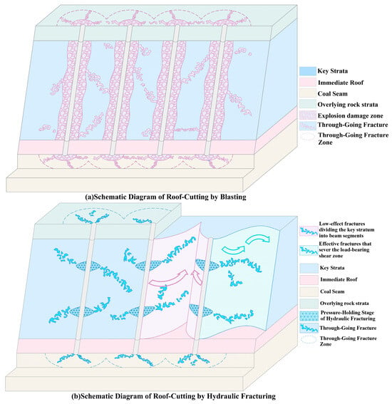
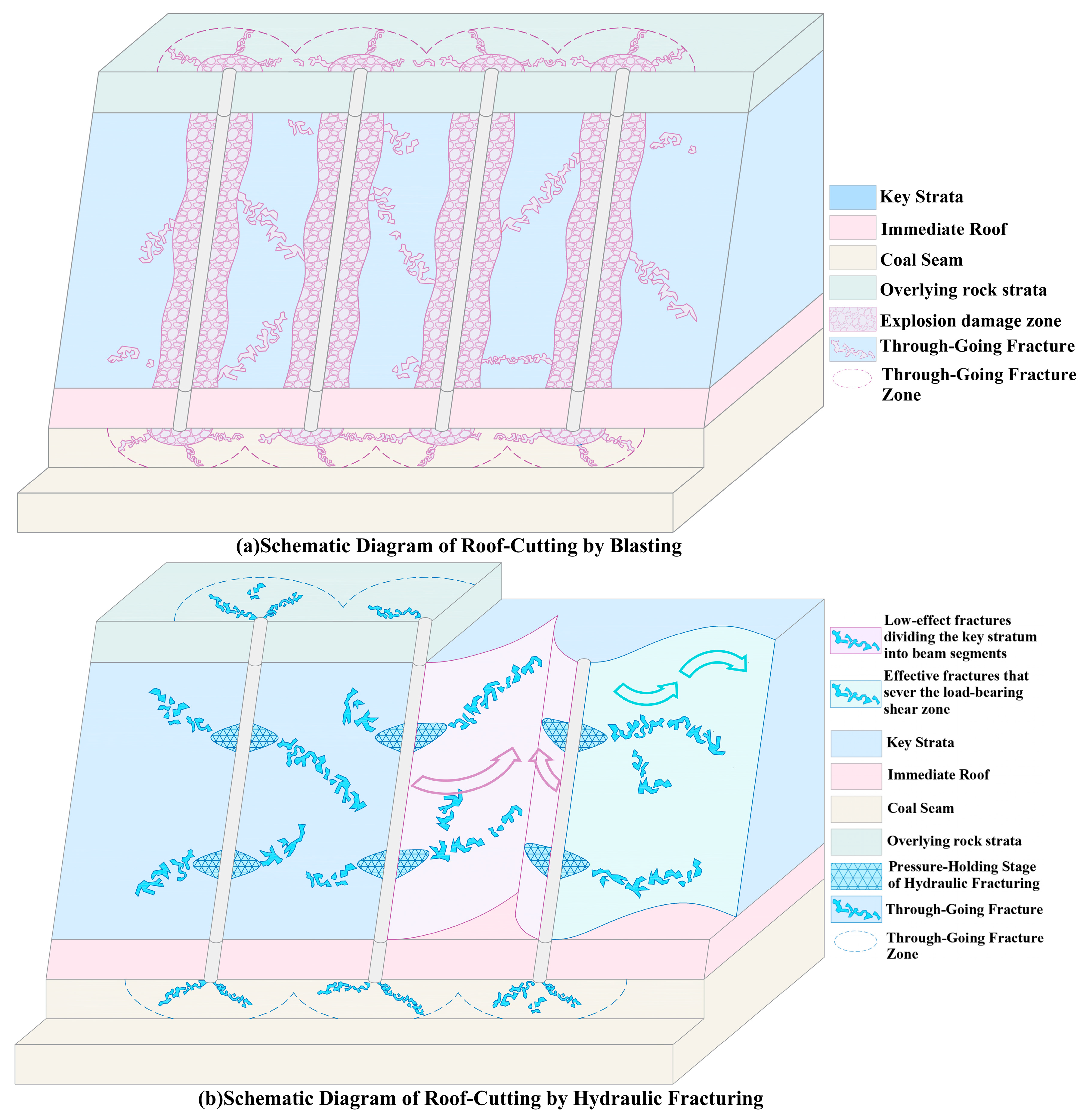
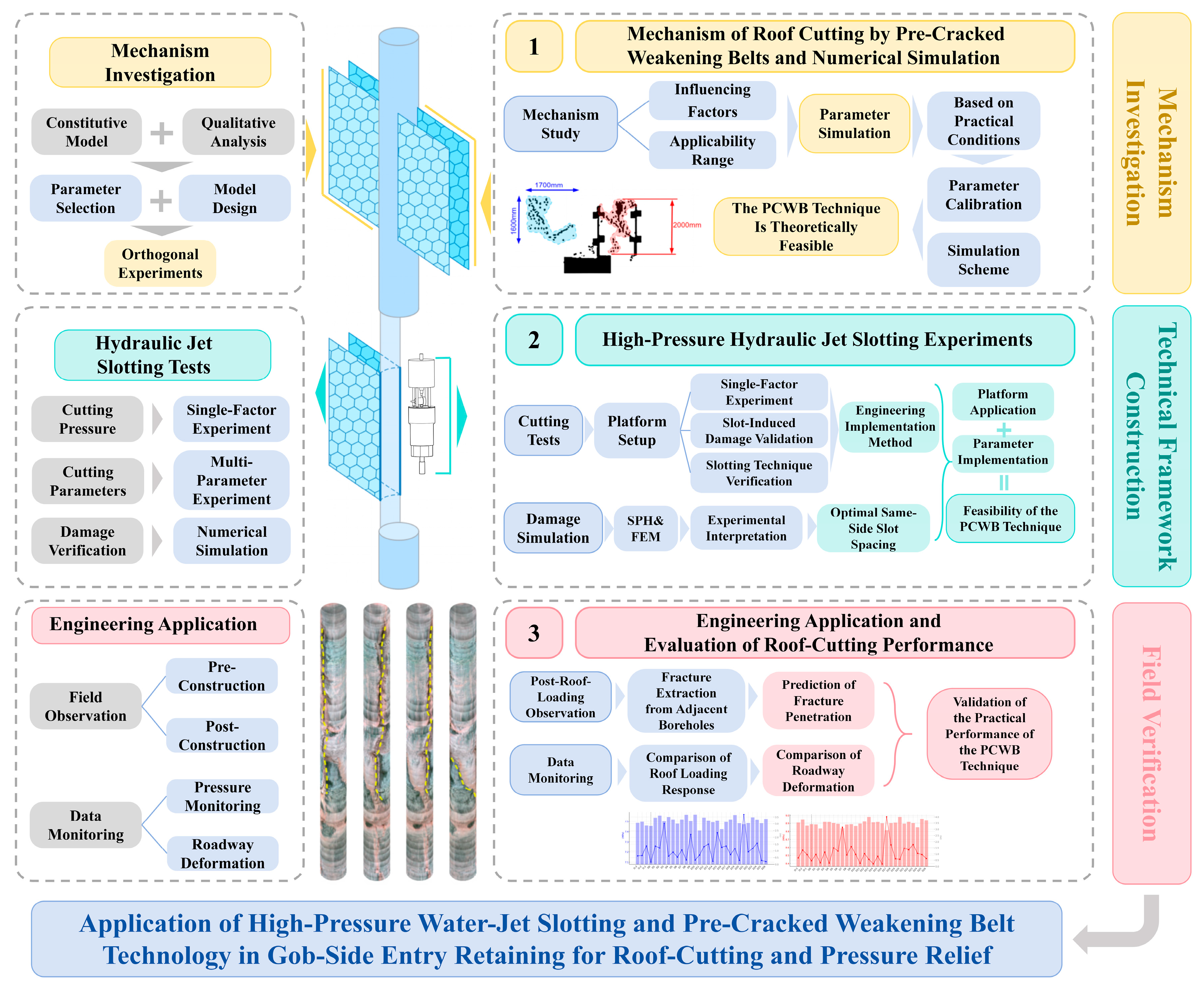
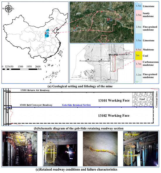
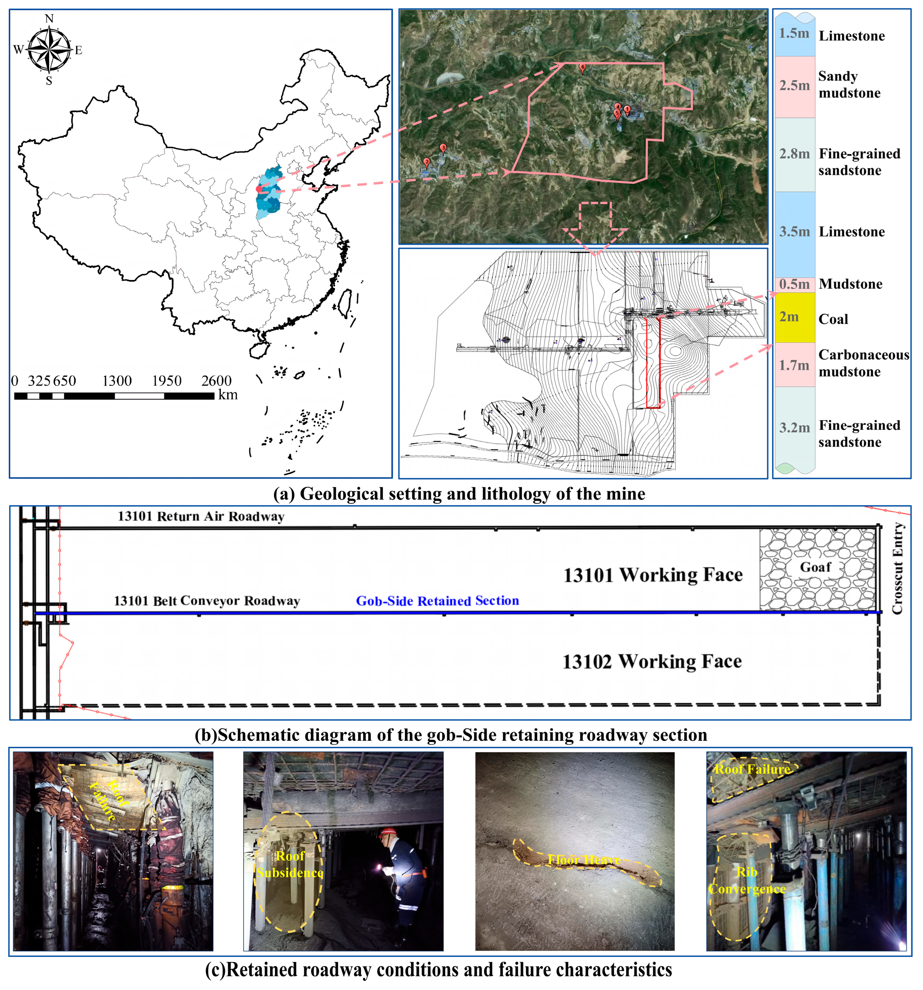
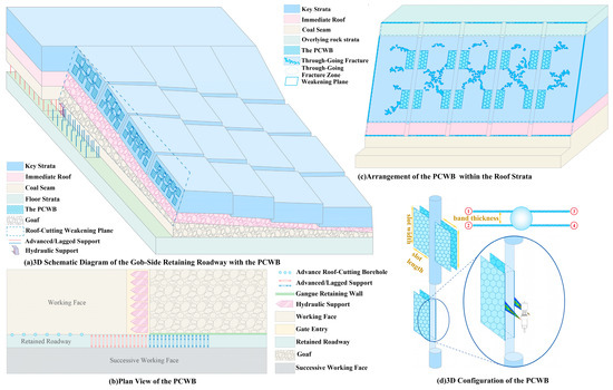
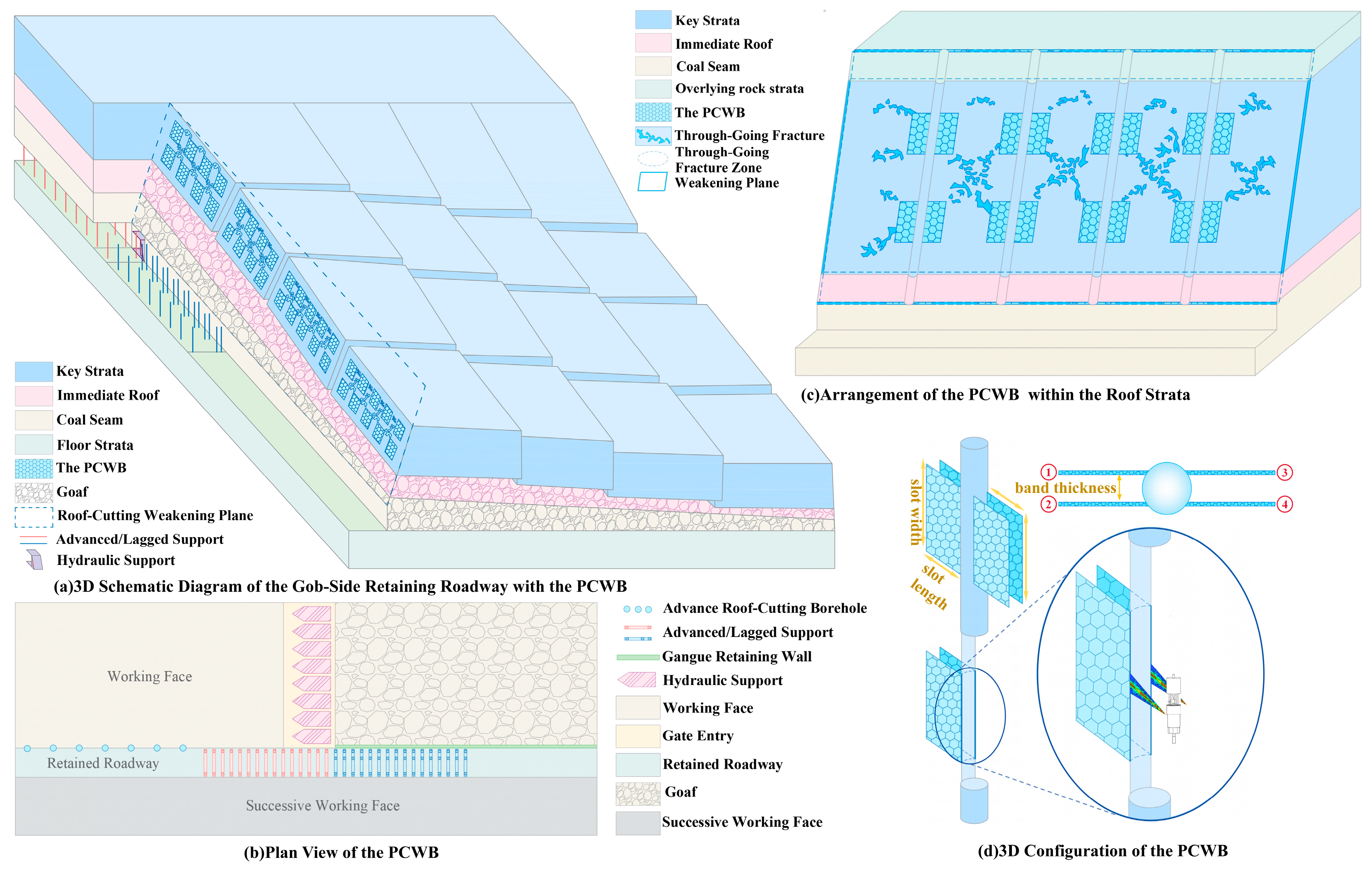
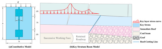
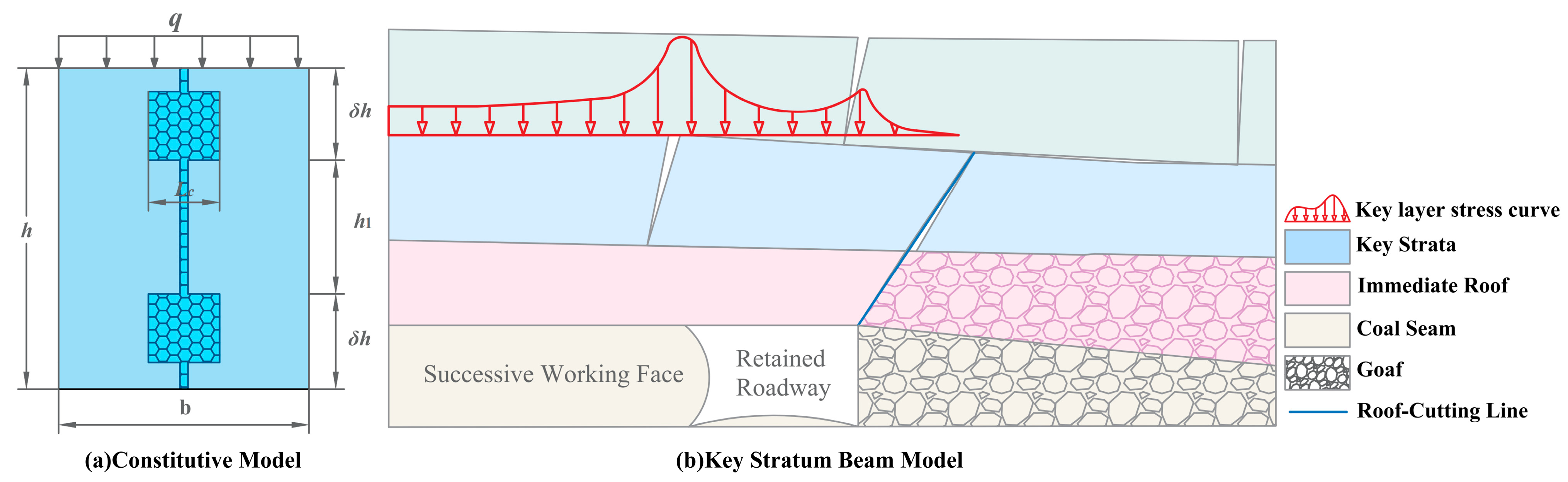
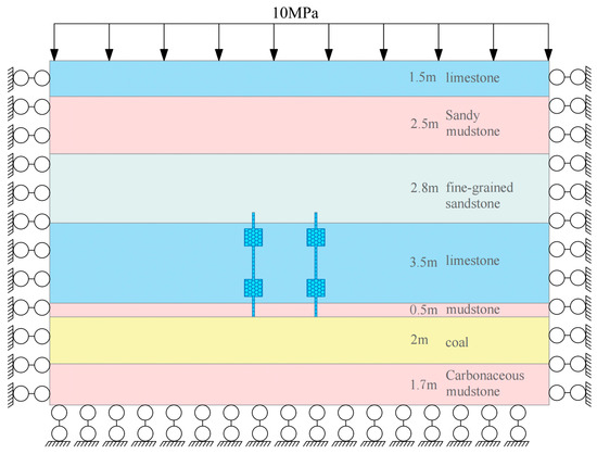
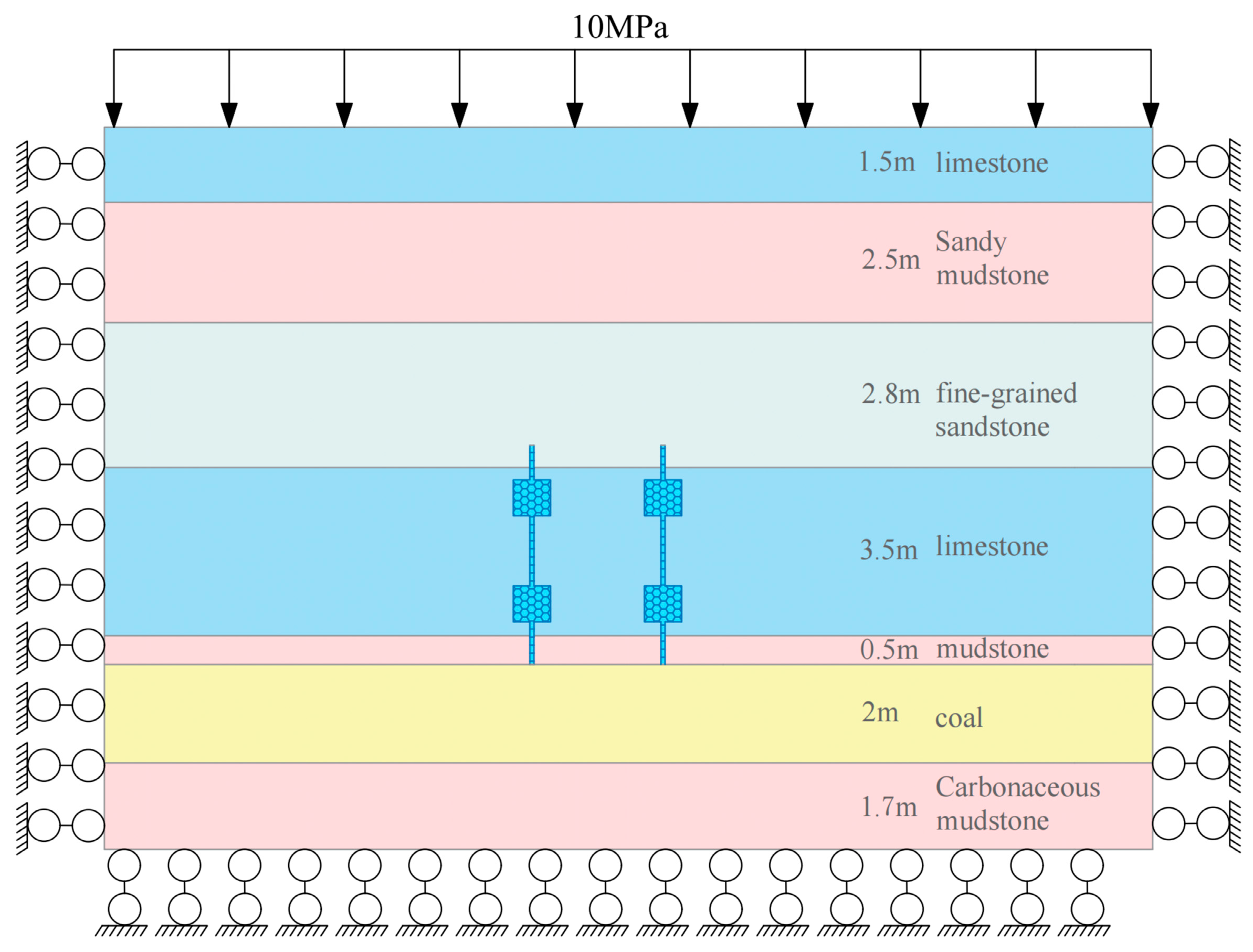
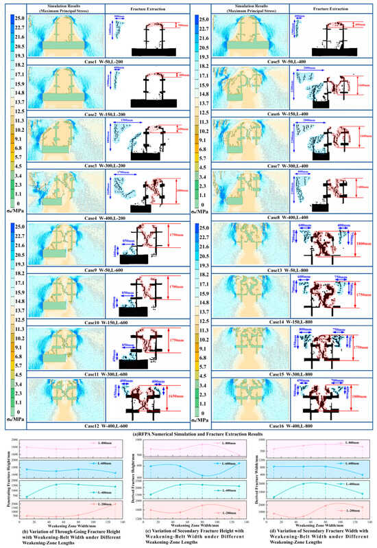
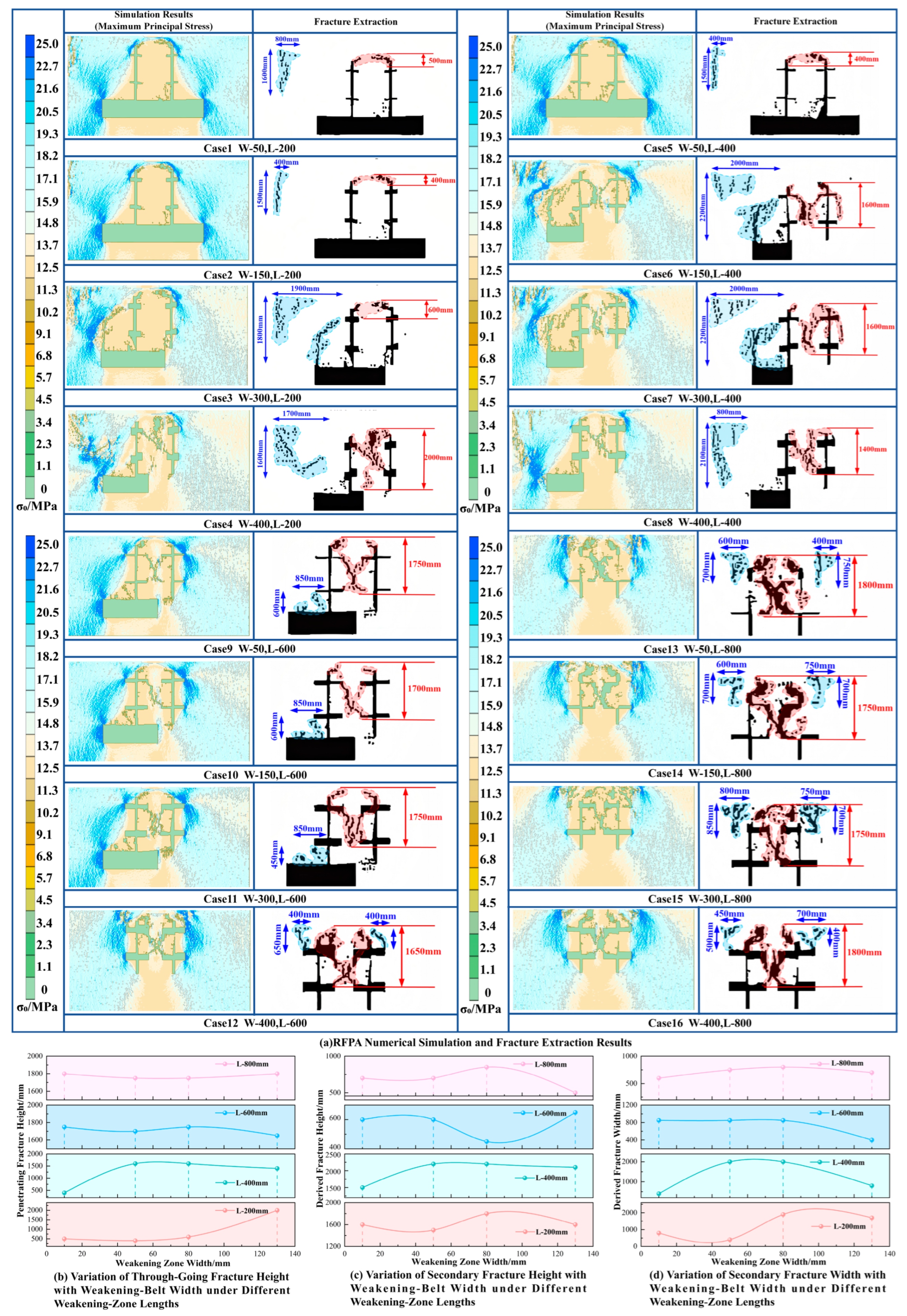
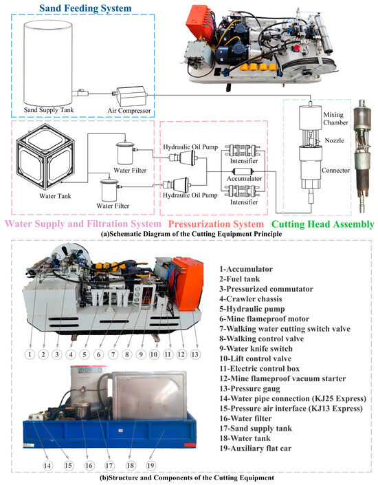
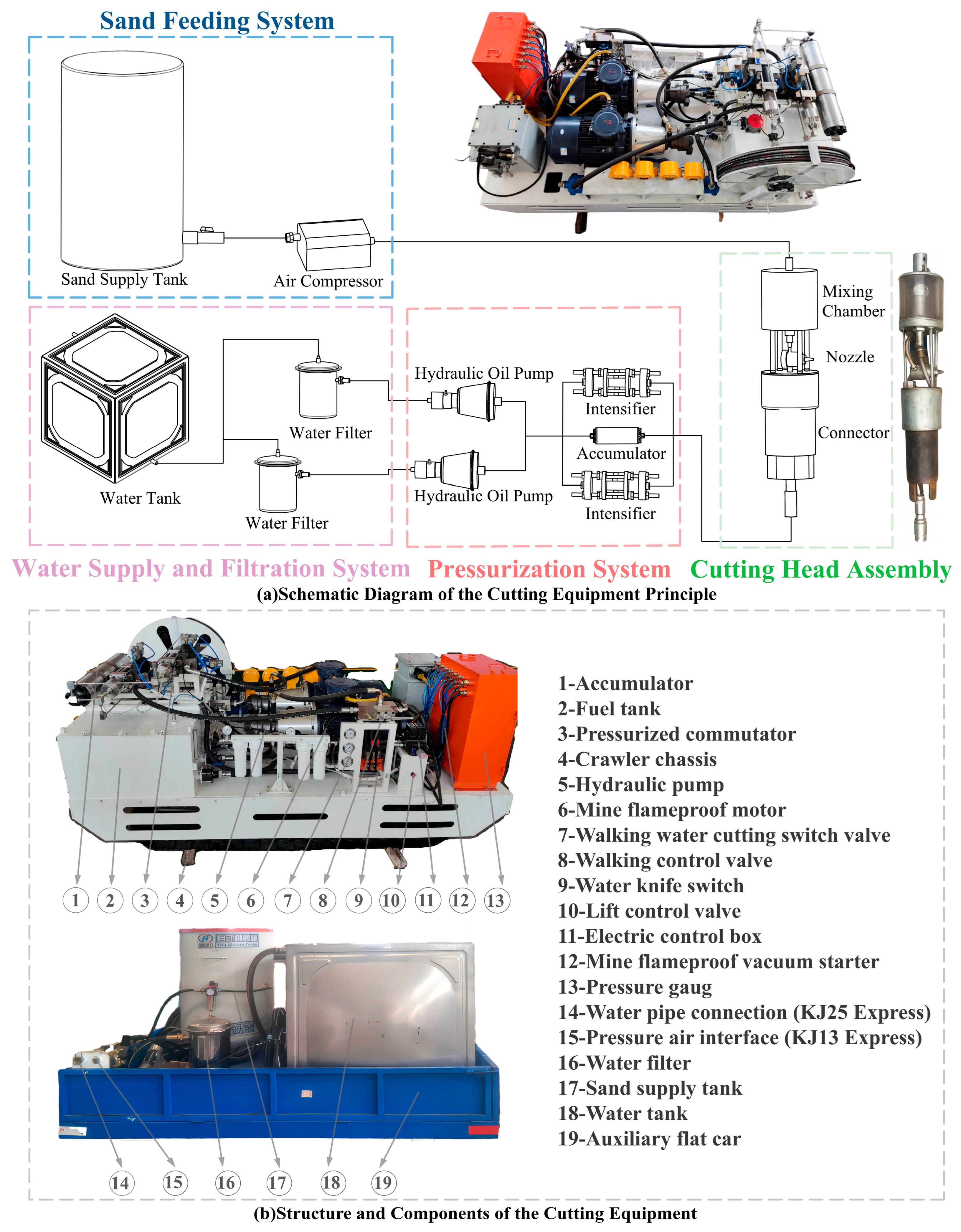
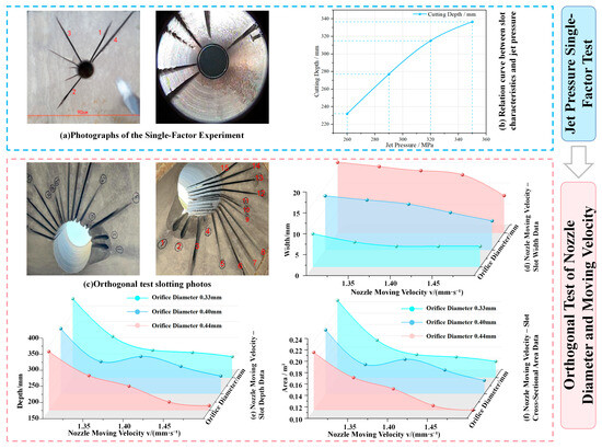
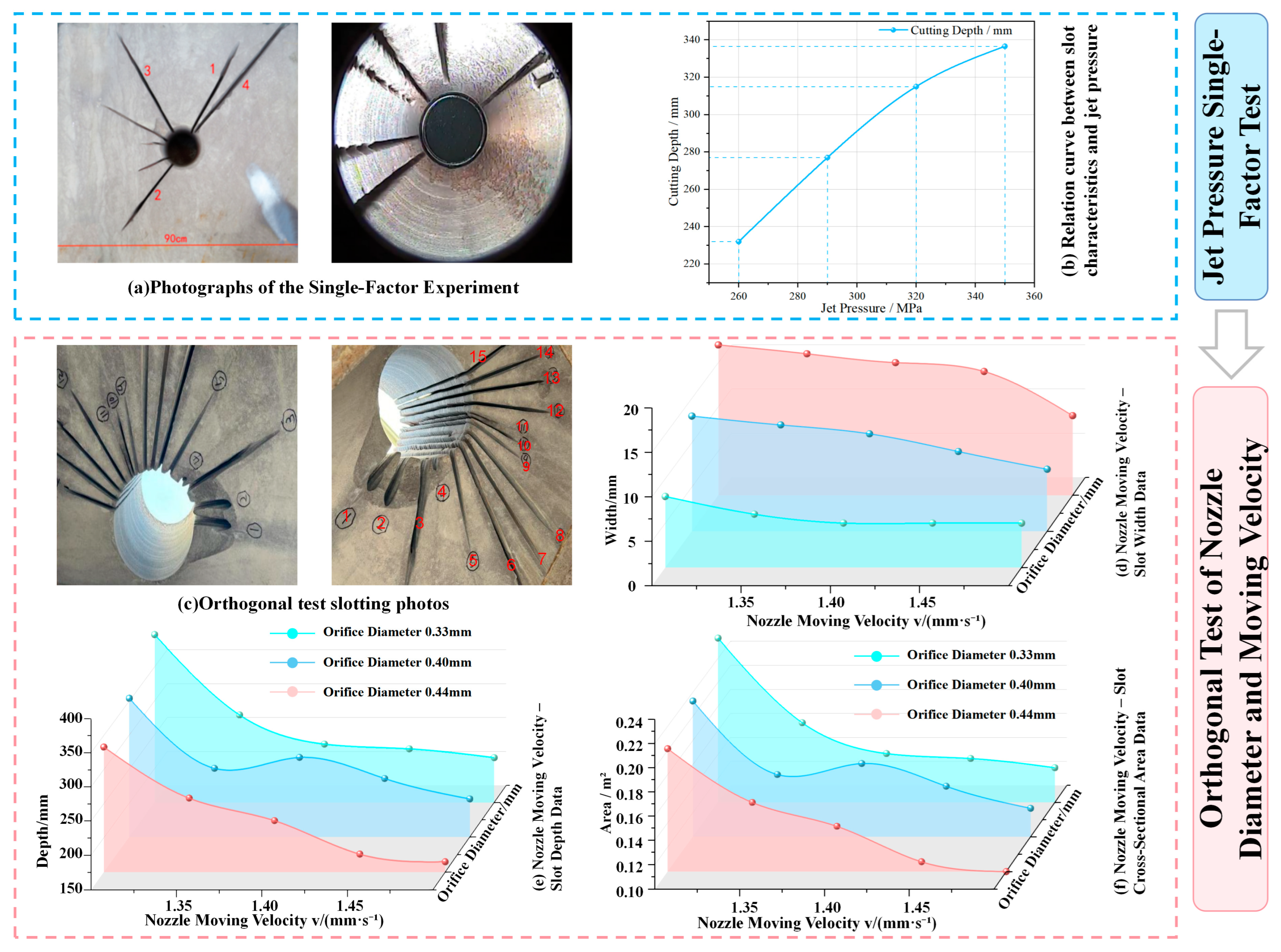
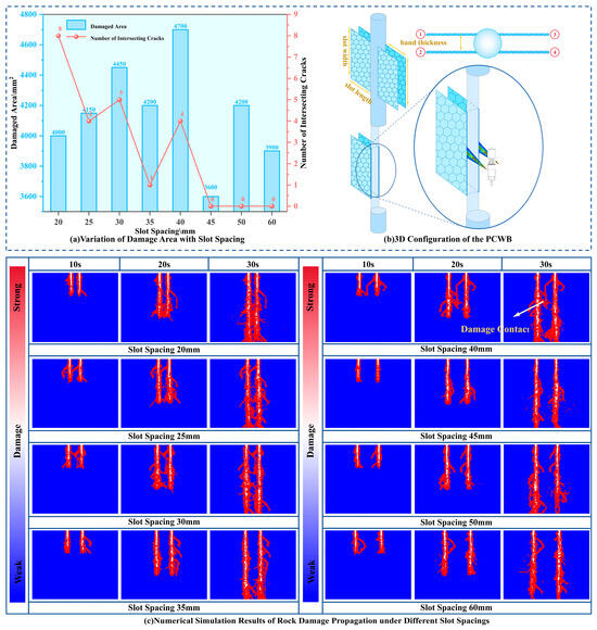
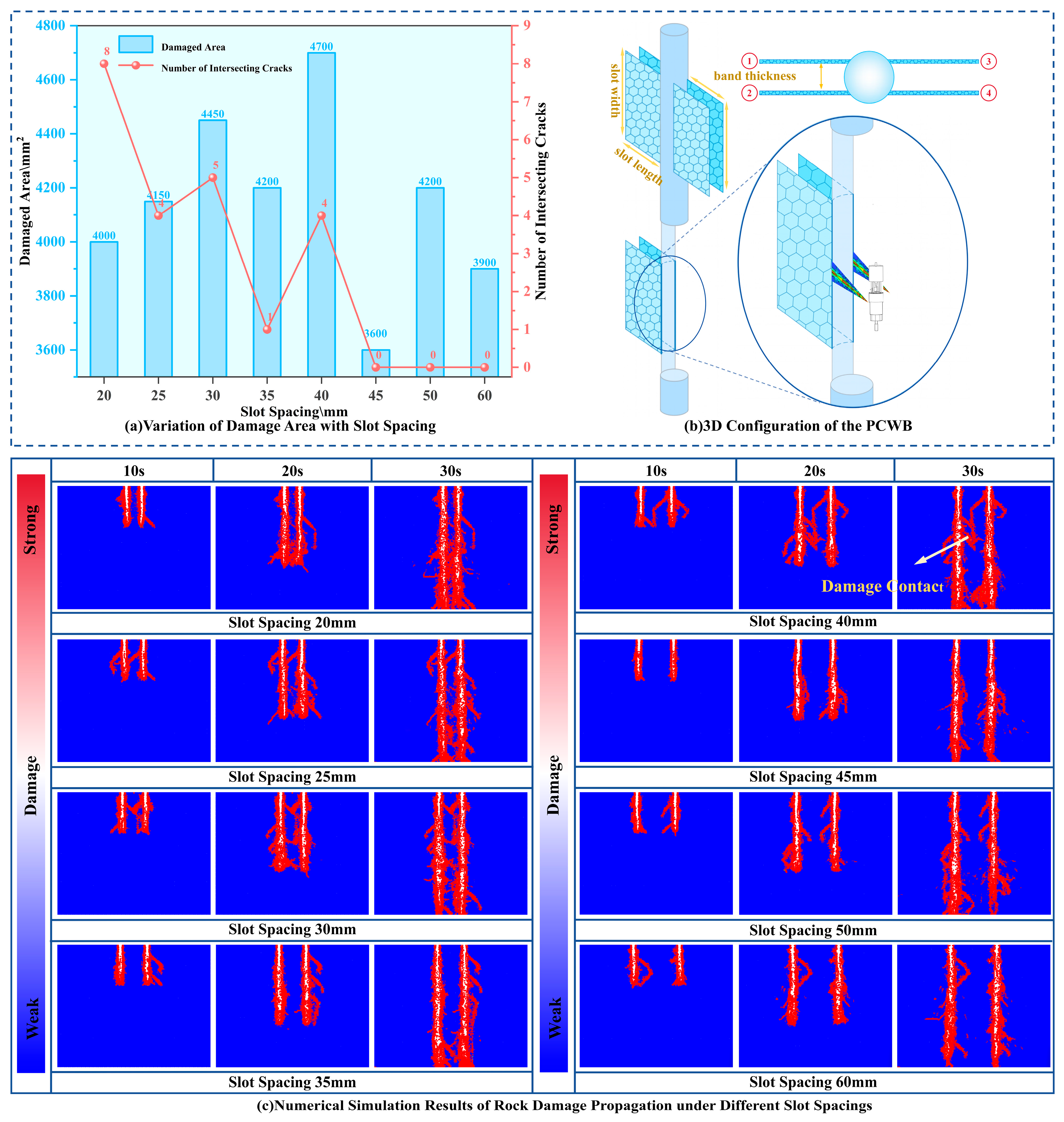
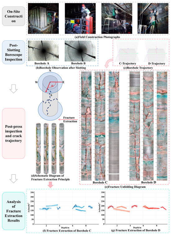
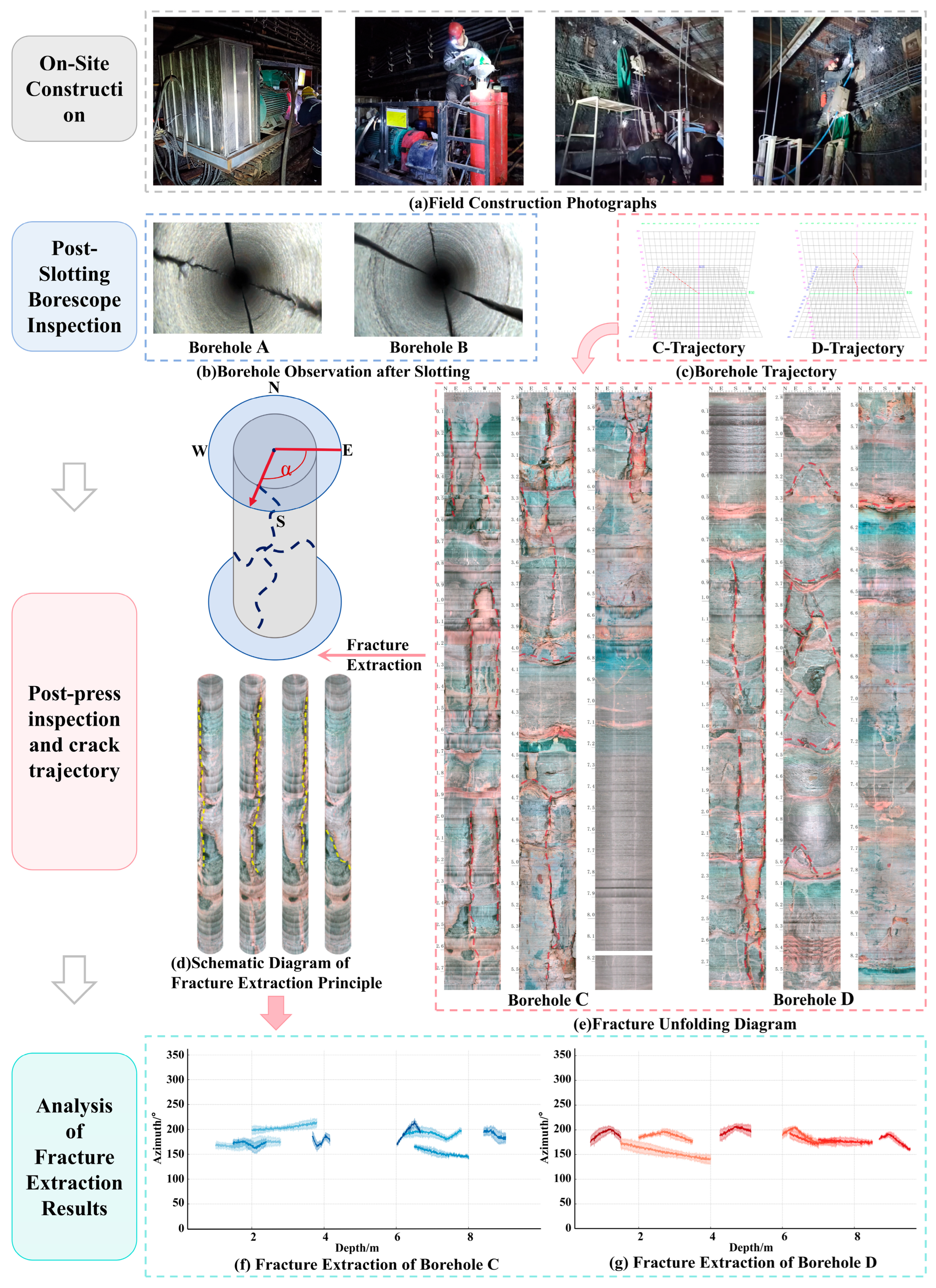
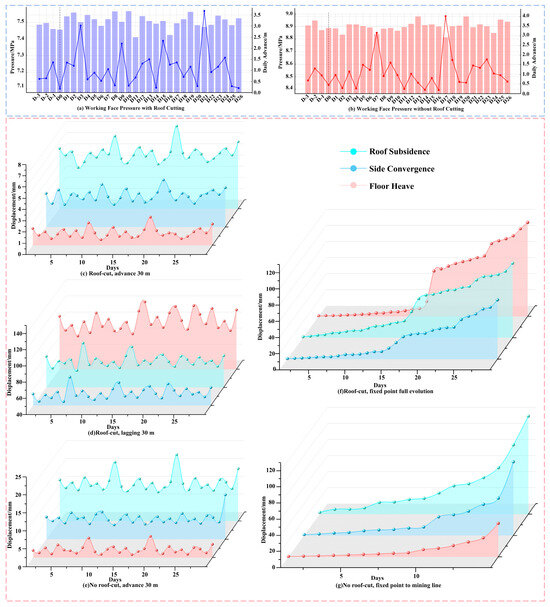
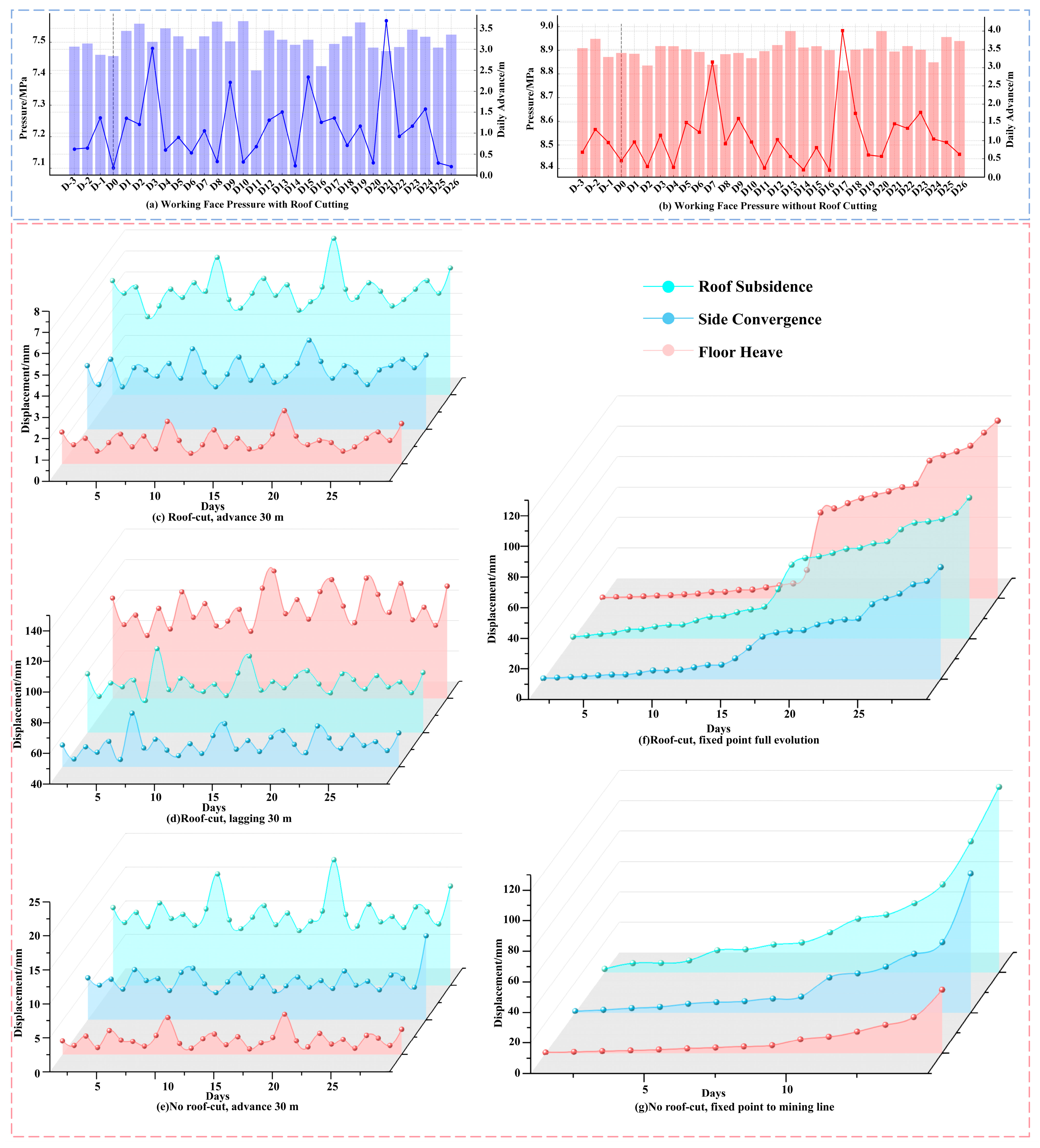

Disclaimer/Publisher’s Note: The statements, opinions and data contained in all publications are solely those of the individual author(s) and contributor(s) and not of MDPI and/or the editor(s). MDPI and/or the editor(s) disclaim responsibility for any injury to people or property resulting from any ideas, methods, instructions or products referred to in the content. |
© 2026 by the authors. Licensee MDPI, Basel, Switzerland. This article is an open access article distributed under the terms and conditions of the Creative Commons Attribution (CC BY) license.