


Abstract
This study integrates physical similarity experiments with numerical simulations to examine how overburden lithology influences roof caving behavior and stress field evolution at a longwall mining face. The results demonstrate that overburden strength significantly governs the timing, extent, and periodicity of roof caving, while also strongly affecting the evolution of mining-induced stress. As lithological strength increases, both damage and displacement within the overburden strata decrease. High-strength roofs exhibit larger caving step distances and longer stress accumulation periods. In contrast, low-strength roofs enter the plastic deformation stage earlier, leading to shorter caving step distances, more frequent caving events, and a wider caving range. During coal seam extraction, roof deformation is accompanied by stress concentration and release, which are processes that are closely associated with dynamic disasters. Due to their higher elastic modulus and compressive strength, high-strength rock strata can accumulate greater elastic strain energy prior to failure. Once instability occurs, the rapid release of stored energy leads to intense stress redistribution and dynamic loading. As lithological strength increases, the stress concentration shell evolves from an arch-shaped structure to a flatter configuration. This transition results in higher internal stress levels and stronger stress concentration, thereby increasing the risk of dynamic disasters such as impact instability. Therefore, maintaining the stability of the stress concentration shell and preventing its migration into deeper strata are essential for ensuring surrounding rock stability and safe mining operations.
1. Introduction
The deformation and stress distribution of overburden rock strata at the mining face are critical factors influencing coal mine safety [1,2,3]. Coal seam mining disrupts the in-situ stress equilibrium, leading to structural adjustment of the overburden and redistribution of stress, which manifests as mining-induced pressure, roof caving, and surface subsidence [4,5,6,7]. This process can be regarded as the coupled evolution involving overburden structure failure and stress field redistribution under mining disturbance. As coal extraction progresses, the formation of the goaf causes the overburden to lose support, resulting in a series of deformation and failure processes, including fracturing, caving, delamination, subsidence, and horizontal movement. This process propagates progressively from the lower strata to the upper strata, eventually affecting the ground surface and establishing a new equilibrium state [8,9]. In addition to its impact on ground deformation, mining-induced overburden failure can significantly alter subsurface gas migration pathways. The development of fractures and surface subsidence, including sinkholes, may lead to abnormal emissions of methane, radon, carbon dioxide, and other gases, thereby posing environmental and safety risks to surrounding populations [10,11,12]. From this perspective, understanding the mechanical behavior of the roof and overburden is also essential for evaluating the temporal evolution of gas migration and emission processes above the goaf. Mining-induced subsidence and its environmental consequences have been widely documented in major coal-producing regions worldwide. For example, in the Upper Silesian Coal Basin of Poland, prolonged underground mining has led to significant surface deformation and infrastructure damage [13,14,15]. Such subsidence is commonly accompanied by the formation of fracture networks that facilitate methane migration. Similar problems have also been observed in the Kuznetsk Coal Basin in Russia and in German coalfields. Accordingly, clarifying the relationships among roof lithology, overburden failure, and fracture evolution is essential for effective ground control, the improved understanding of gas migration, and the mitigation of related environmental risks.
In both engineering practice and laboratory experiments, rock failure is primarily dominated by tensile fractures mechanisms, which are strongly influenced by stress conditions and environment factors [16,17,18,19,20,21]. Cui et al. [22] investigated the influence of loading rate on fracture surface morphology, while Liu et al. [23] and Zhang et al. [24] further analyzed the tensile strength and fracture characteristics of rock materials under varying conditions. Previous studies have demonstrated that the magnitude and spatial distribution of mining-induced stress are controlled by multiple factors, including coal seam thickness, rock strength, mining depth, and mining face geometry [25,26,27]. In addition to these factors, mining methods also play a crucial role in controlling overburden deformation and roof subsidence. Different mining technologies can significantly alter the stress redistribution process and the structural response of the overburden [28,29]. For instance, cut-and-fill mining technology provides artificial support to the overlying strata, effectively limiting roof subsidence and reducing the extent of overburden failure. During mining, a “stress concentration shell” composed of high-stress force chains is often formed within the surrounding rock strata. This structure plays a key role in load transfer and is widely recognized as the primary load-bearing system of the overburden, significantly influencing [30,31] mining-induced pressure behavior and structural stability. Moreover, variations in mining geometry and operational parameters can alter the spatial distribution and evolution of the stress field [32,33]. Recent studies have further explored the evolution of mining-induced stress fields and overburden structures under complex conditions. For example, Lou et al. [34] analyzed the evolution of stress fields in longwall mining through physical modeling and revealed the formation of stress arch structures and the spatial redistribution characteristics of stress during coal extraction. Similarly, Ma et al. [35] investigated stress distribution and overburden migration using similarity simulation experiments, demonstrating the dynamic evolution of stress and progressive compaction behavior of the overburden during mining. These studies provide important insights into stress evolution and structural response, but primarily focus on macroscopic stress distribution and deformation characteristics.
The physical and mechanical properties of roof strata play a decisive role in controlling the deformation and failure behavior of the overburden. Differences in lithology directly affect the load-bearing capacity, deformation characteristics, and failure modes of the roof, thereby influencing the spatiotemporal evolution of the mining-induced stress field [36,37,38]. Roof strength is a key parameter governing roof stability, and it is influenced by factors such as compressive strength, structural plane development, water content, and stratification characteristics [39,40,41]. Under mining disturbance, low-strength roofs tend to exhibit early plastic deformation, frequent caving, and progressive failure behavior, whereas high-strength roofs can accumulate higher stress and elastic energy before undergoing sudden instability, often accompanied by strong dynamic effects [42,43,44,45]. In addition, Yan et al. [46] investigated fracture evolution mechanisms in thick coal seam mining under complex overburden conditions using combined physical and numerical approaches, demonstrating that lithological differences significantly influence crack propagation patterns and fracture development processes. Although these studies highlight the importance of lithology, systematic comparative analysis of overburden caving behavior and stress field evolution under varying lithological conditions remain limited.
Although significant progress has been made in understanding mining-induced stress evolution and overburden failure mechanisms, most studies primarily focus on macroscopic deformation behavior or stress redistribution under specific mining conditions [47,48,49,50,51]. The internal damage evolution process, particularly the spatiotemporal characteristics of microfracture development under varying lithological conditions, has not been adequately explored. Acoustic emission (AE) monitoring provides an effective tool for capturing the initiation, propagation, and coalescence of microcracks in rock masses. However, the integration of AE spatial distribution with overburden caving behavior and stress concentration shell evolution remains limited. Furthermore, while the stress concentration shell has been widely studied, its morphological evolution and mechanical response under different lithological conditions, as well as its relationship with energy accumulation and release, are not yet fully understood.
To address these gaps, this study investigates the influence of roof lithology on overburden caving behavior, stress field evolution, and microfracture development using a combination of physical similarity experiments, numerical simulations, and AE monitoring. Two representative physical models with high-strength and low-strength roofs are used to capture the boundary characteristics of overburden response, while numerical simulations are employed to extend the analysis to intermediate lithological conditions. Deformation characteristics, caving step distance, stress concentration shell evolution, and AE spatial distribution are systematically analyzed.
The main contributions of this study are as follows:
- A systematic comparative analysis of overburden caving behavior and stress field evolution under different roof lithological conditions is provided;
- Acoustic emission monitoring is introduced to reveal the microfracture evolution process of overburden rock strata;
- The coupling relationship between roof lithology, stress concentration shell evolution, and AE characteristics is established, providing new insight into the mechanical mechanism of dynamic instability in coal mining.
2. Materials and Methods
2.1. Engineering Background
This study is based on the geological conditions of the 1014 mining face in Yushuquan Coal Mine, located in the A’ai mining area of Xinjiang, China. The coalfield extends approximately 5.5–6.7 km in the east–west direction and 1.79–2.61 km in the north–south direction, covering an area of about 12.26 km2 (Figure 1a). The 1014 mining face has an irregular rectangular shape, with a strike length of 175 m in slant length and an average coal seam thickness of 4 m. The coal seam structure is relatively simple. The mining face extends from west to east, and the coal seam dip ranges from 5° to 11°. The coal seam is stable and can be classified as gently dipping. As mining progresses, the coal seam gradually thickens from west to east (Figure 1b).
Figure 1.
Location of Yushuquan Coal Mine and the layout of the mining face: (a) coal mine area; (b) layout of the 1014 mining face.
Core sampling was conducted in the tunnel roof above the 1014 mining face to determine the physical and mechanical properties of the overlying rock strata. The mechanical parameters of the rock and coal samples were determined through laboratory testing. The detailed results are shown in Figure 2. Rock Quality Designation (RQD) is a widely used index for evaluating rock mass quality. It is defined as the percentage of intact core segments longer than 100 mm relative to the total core length [52,53]. In engineering practice, thick–hard roofs are typically characterized by thickness, hardness, and structural integrity. Thick rock strata are generally defined as having a single-layer thickness of ≥5 m or a combined thickness of ≥8–10 m [54,55]. Hardness is typically defined as a uniaxial compressive strength greater than 60 MPa [56]. Structural integrity indicates that fractures and bedding planes are not well-developed [57]. The roof above the 1014 mining face has a thickness of 13 m, a uniaxial compressive strength of 81.9 MPa, and an RQD value of 88%. These parameters indicate that the roof can be classified as a typical thick–hard roof.
Figure 2.
Overview of the 1014 mining face.
2.2. Establishment of the Physical Model
This physical experiment is based on the geological conditions of the 1014 mining face at the Yushuquan Coal Mine in Xinjiang, China. It includes physical simulation experiments under both high-strength and low-strength roof conditions. The physical model measures 170 cm × 30 cm × 100 cm and adopts a geometric similarity ratio of 100, representing a real rock strata range of 170 m × 30 m × 100 m. The detailed parameters of the model are presented in Table 1.
Table 1.
Similarity ratios of material parameters used in the physical model.
To replicate the actual rock strata and coal layers, the model uses a mixture of fine sand, gypsum, lime, and water. Coal and rock layers of varying strengths are simulated using proportionally adjusted similarity materials. The specific material proportions and strength parameters are listed in Table 2. The rock strata are constructed layer by layer according to geometric scaling, with each layer having a thickness of 2 cm. Mica powder is added between the layers to simulate the joints. Stress monitoring sensors are embedded during the layering process to track changes in the overburden rock strata stress throughout the mining simulation. After construction, the model is left to dry naturally. Testing begins once the moisture has fully evaporated. The boundary conditions and loading methods were identical for both physical models. The lower boundary was defined as a displacement boundary, whereas the upper and lateral boundaries were treated as stress boundaries.
Table 2.
Parameters and proportions of rock in different strength overburden.
2.3. Monitoring System and Experimental Procedure
Stress evolution and AE activity were continuously monitored during the mining process using an integrated system, as shown in Figure 3. The stress monitoring system consisted of strain gauges, a static strain gauge instrument, and a computer for data acquisition. The AE monitoring system included AE sensors, preamplifiers, a data acquisition unit, and a computer. A hydraulic loading system was applied to the top and lateral surfaces of the model to simulate in-situ stress conditions. Because the physical model could not fully replicate the actual thickness of the overburden strata, equivalent stresses were applied. Specifically, a vertical stress of 0.09 MPa was applied to the top surface, and a lateral stress of 0.11 MPa was applied to both sides. A total of 96 stress monitoring points and 40 AE monitoring points were installed at different stratigraphic levels within the model. The stress sensors recorded the stress components (σx, σy, and τxy) at each monitoring location. Meanwhile, the AE sensors recorded the number of emission events throughout the experiment.
Figure 3.
Physical model and monitoring system.
Protective coal pillars were retained on both sides of the physical model to minimize boundary effects. Mining was conducted incrementally, with the coal seam excavated in 5 cm steps over a total of 26 cycles. After each excavation step, a stabilization period was introduced to allow sufficient stress transfer and redistribution within the surrounding rock mass before proceeding to the next mining stage.
2.4. Numerical Simulation Method
To extend the analysis to a broader range of lithological conditions, numerical simulations were conducted using FLAC3D (Fast Lagrangian Analysis of Continua in 3 Dimensions, Itasca Consulting Group, Inc., Minneapolis, MN, USA), which is a widely used finite-difference software for geotechnical analysis. The numerical model was developed based on the geological conditions of the 1014 mining face. Different roof lithologies were simulated by assigning varying mechanical parameters to the rock layers.
Five roof-strength conditions were considered: high strength (80 MPa), medium–high strength (60 MPa), medium strength (30 MPa), medium–low strength (15 MPa), and low strength (5 MPa). The rock mass was assumed to be continuous, homogeneous, and isotropic. The Mohr–Coulomb constitutive model with strain-softening behavior was adopted to simulate the progressive failure of the rock mass. This model allows the mechanical properties of the material to degrade with increasing plastic deformation, thereby reflecting realistic failure processes in rock strata. The boundary conditions were defined as follows. Horizontal displacement constraints were applied to the lateral boundaries, vertical displacement was restricted at the bottom, and a vertical load was applied at the top to simulate the overburden weight. The model was discretized into zones representing different rock layers. Each zone was assigned appropriate mechanical parameters based on laboratory tests and field data.
3. Impact of Roof Strength Surrounding Rock at the Mining Face
3.1. Analysis of Roof-Caving Characteristics
The strength of the overburden rock strata is a key factor influencing roof-caving behavior. Previous studies [58,59,60] have shown that rock strata with different strengths exhibit distinct deformation characteristics, which directly influence the pattern and extent of roof caving. High-strength strata generally exhibit greater stability; however, significant roof caving may still occur under mining disturbances. Therefore, analyzing the influence of rock strength on roof-caving behavior is essential for coal mine safety assessment and the design of monitoring systems.
Figure 4a illustrates the roof-caving behavior of high-strength and low-strength roofs during coal seam mining. The initial caving step distance is 40 cm for the high-strength roof and 30 cm for the low-strength roof. During periodic caving, the caving step distance for the high-strength roof ranges between 10 and 15 cm, while for the low-strength roof, it ranges from 5 to 15 cm. These results indicate that rock strength significantly influences the caving step distance. Higher-strength strata tend to exhibit larger step distances during caving, likely due to stress concentration and the degree of fissure development.
Figure 4.
Roof-caving behavior of high-strength and low-strength roofs during coal seam mining: (a) roof caving in high-strength and low-strength roof models; (b) analysis of caving height and step distance.
Figure 4b presents the relationship between caving height and step distance. In terms of caving range, the maximum caving height is 53.1 cm for the high-strength roof and 72.1 cm for the low-strength roof. As rock strength increases, the caving height decreases significantly. This suggests that high-strength rock strata tend to exhibit more uniform behavior under mining disturbance, resulting in a more localized caving area. In contrast, low-strength roofs may experience more widespread damage due to uneven stress distribution, thereby increasing both the range and height of caving.
As the strength increases, both the extent and range of damage to the surrounding rock decrease. The caving area of low-strength roofs shows relatively uniform changes in height. As the mining face advances, the caving height increases steadily, indicating a relatively stable caving process and a more uniform damage distribution. In contrast, the caving height of high-strength roofs exhibits irregular variations. During the first seven caving events, the caving height changes steadily. However, during the eighth caving, the caving height increases abruptly, leading to a large-scale roof collapse. This abrupt increase suggests that initial caving in high-strength rock strata may be constrained by rock strength. Once stress concentration reaches a critical threshold, sudden catastrophic failure may occur, posing significant risks. In summary, roof strength influences not only the caving step distance but also the range and height of roof caving. High-strength roofs exhibit larger initial and periodic caving step distances than low-strength roofs, reflecting greater load-bearing capacity and delayed failure. However, as periodic caving progresses, irregular behavior and sudden large-scale collapses may occur. In contrast, low-strength strata exhibit a more uniform damage process, characterized by a larger caving range and steady changes in caving height.
3.2. Evolution of the Stress Field
In coal mining, the distribution of the stress field within the surrounding rock is critical to the stability of the overburden rock strata. The stress distribution within the overburden rock strata is closely related to mining methods, mining depth, and roof strength. Variations in roof strength influence the load-bearing capacity, deformation behavior, and failure characteristics of the overburden rock strata. These factors govern stress redistribution in the surrounding rock and ultimately affect mining face stability.
Before coal extraction, the overburden exists in a state of triaxial stress equilibrium. As mining disturbance intensifies, this equilibrium is disrupted, resulting in stress redistribution within the overburden. Figure 5a and Figure 5b, respectively, present the stress contour of the high-strength and low-strength roofs during coal seam mining. During the initial mining stage, mining-induced stress in the overburden increases gradually and becomes concentrated directly above the goaf. As mining progresses, roof stress continues to increase, forming an arch-shaped stress concentration shell above the goaf. As the mining face advances, stress within the concentration shell increases until it reaches the roof-strength limit, ultimately leading to roof caving.
Figure 5.
Stress field of overburden rock strata with different lithologies: (a) high-strength roof; (b) low-strength roof.
After roof caving, the stress field within the goaf redistributes, and stress is gradually transferred to the upper rock strata. This redistribution alters the spatial configuration of the stress concentration shell. The arch foot shifts forward into the rock mass, while the arch crown propagates upwards into the overburden until it reaches the model boundary. The stress concentration shell partially shields the lower strata from the load of the overlying rock mass. Under equilibrium conditions, the self-weight of the rock strata induces bending and subsidence, resulting in layer separation. When the stress exceeds the bearing capacity of the overburden, roof caving occurs and the original stress concentration shell gradually dissipates. As stress redistributes, new stress concentration zones migrate upward, causing the roof to transition from an unstable state to a stable state. As the goaf expands, the stress concentration shell undergoes continuous destruction and re-equilibration. This results in cyclic transitions between instability and equilibrium. Ultimately, this process governs the evolution of the mining-induced stress concentration shell in the overburden.
Roof lithology plays a crucial role in shaping the distribution of the stress concentration shell within the overburden rock strata. In low-strength roofs, caving occurs more frequently, resulting in repeated local stress fluctuations. These fluctuations trigger multiple caving events and produce a multi-layered stress distribution. In contrast, high-strength roofs can withstand higher stress levels. As roof strength increases, stress within the concentration shell rises, and its distribution evolves from an arch shape to a flatter configuration. The maximum stress is 373 kPa (equivalent to 59.7 MPa in situ) for the high-strength roof and 265 kPa (equivalent to 26.4 MPa in situ) for the low-strength roof. As the stress concentration area expands, exceeding the bearing capacity of the overburden rock strata can lead to impact instability and potentially trigger dynamic disasters. This behavior reflects the mechanical mechanisms underlying dynamic disasters in complex surrounding rock conditions.
Figure 6 presents statistical data on the stress concentration shell and roof caving height for roofs with varying strengths. It also includes a variation curve illustrating the difference between the stress concentration shell height and the caving height. With periodic roof caving, both the stress concentration shell height and the caving height increase progressively. These heights are significantly greater in low-strength roofs than in high-strength roofs. The curve representing the height difference between the stress concentration shell and the caving area shows that this difference is much larger in low-strength roofs. This indicates that, as roof strength increases, the ratio of arch height to arch width within the stress concentration shell decreases. The transition of the stress concentration shell from an arch-shaped structure to a flatter form is primarily governed by lithology-dependent mechanical properties. In low-strength roofs, frequent caving leads to rapid stress release. The load transfer follows a typical arching mechanism, with stresses redistributed along curved trajectories toward the abutments. As roof strength increases, the rock mass exhibits greater stiffness and load-bearing capacity, enabling it to sustain higher stress without immediate failure. Consequently, stress distribution becomes more uniform, and the curvature of principal stress trajectories decreases. As a result, the stress concentration shell gradually evolves into a flatter configuration. From a mechanical perspective, this transformation reflects a transition from a stress redistribution-dominated system (low-strength roof) to a stress accumulation-dominated system (high-strength roof).
Figure 6.
Comparison of stress concentration shell characteristics and roof-caving height under different roof-strength conditions.
3.3. Spatial Distribution of Acoustic Emission Events
AE sensors detect microfractures in rock over time by recording and accumulating AE events. In this study, a dynamic AE monitoring system was used to accurately locate fracture initiation and track the fracturing process of the overburden induced by mining disturbance. The spatial distribution of AE events effectively delineates damaged zones in the rock strata and reveals crack evolution patterns. Figure 7 illustrates the spatial distribution of AE events obtained from physical models with high-strength and low-strength roofs during coal seam mining. In this figure, the diameter of each sphere represents the magnitude of AE energy release.
Figure 7.
Spatial distribution of AE events of overburden rock strata with different lithologies: (a) high-strength roof; (b) low-strength roof.
AE events are primarily concentrated near the boundary of the caving zone, indicating that this boundary plays a critical role in crack propagation. This phenomenon is likely associated with stress concentration, material heterogeneity, and localized failure mechanisms. The number of AE events in the high-strength roof is lower than that in the low-strength roof. However, AE activity in the high-strength roof is characterized by higher amplitudes, greater energy release, and a more concentrated spatial distribution. This behavior can be attributed to the higher strength of the roof material, which promotes stronger stress concentration and leads to more intense energy release during crack propagation, resulting in more pronounced AE responses. Additionally, within the same model, the fine sandstone layer exhibits higher AE energy release. This is because fine sandstone has higher compressive strength and gradually accumulates strain energy under bending deformation induced by mining disturbance.
The spatial distribution of AE events is highly heterogeneous, with significantly more events occurring in the upper overburden than in the lower strata. This distribution reflects spatial variations in crack propagation during roof caving. The localization of AE events reveals the evolution of microfractures during the macroscopic failure of the overburden. AE events extend from the center of the roof-caving zone toward both sides, forming a distribution pattern consistent with the caving geometry and exhibiting a trapezoidal shape. These events are mainly concentrated along the macroscopic fracture line of the overburden rock.
Crack propagation at different stages exhibits distinct AE count characteristics, as shown in Table 3. During the crack initiation stage, both the number of AE events and the released energy are low. During stable crack propagation, both AE event counts and energy gradually increase, indicating that cracks propagate steadily under the material’s load-bearing capacity. When cracks enter the unstable propagation stage, AE event counts increase sharply, exhibiting an exponential growth trend. This behavior is associated with rapid crack propagation and brittle failure, marking the transition to an irreversible failure process.
Table 3.
Parameters of AE events during coal seam mining.
Roof-caving events at different stages also exhibit significant differences in AE event counts. For example, during the eighth roof-caving event in the high-strength roof, large-scale damage and rapid stress release led to a significant increase in both AE event count and energy. This event accounts for approximately 39% of the total AE events. This observation indicates that roof caving involves not only localized damage but also large-scale energy transfer and release. The spatial distribution of AE events indicates that microfracture development is strongly controlled by lithological strength and stress concentration. Under high-strength roof conditions, AE events exhibit higher energy release and stronger spatial clustering, indicating substantial elastic energy accumulation and sudden brittle failure. In contrast, low-strength roofs exhibit more dispersed AE distributions, reflecting progressive damage and stable crack propagation. These differences suggest that lithology governs not only macroscopic caving behavior but also microfracture evolution, thereby directly influencing the dynamic response of the overburden system.
4. Analysis of the Stress Concentration Shell in the Overburden Rock Strata
4.1. Method for Determining the Extent of the Stress Concentration Shell
Prior to coal seam excavation, the overburden rock strata are in a state of stress equilibrium. However, mining activities progressively disrupt this equilibrium, leading to stress redistribution and transfer within the surrounding rock mass. As the stress state evolves, portions of the rock mass may exceed the elastic limit and enter a plastic state. Consequently, four distinct zones develop sequentially from the goaf to the deeper overburden, each corresponding to a stage of the rock stress–strain curve, as shown in Figure 8.
Figure 8.
Stress–strain curve and subdivisions of the overburden rock strata.
Following coal seam extraction, stress redistribution occurs in the overburden, and the roof undergoes a progressive transition from stability to instability:
Elastic zone: Deformation follows Hooke’s law, with a linear relationship between stress and strain.
Plastic hardening zone: Rock strength increases but remains below its ultimate capacity, and no instability occurs.
Plastic softening zone: Rock strength decreases progressively, leading to significant deformation and potential failure.
Fracture zone: The overburden rock strata experiences fracturing and roof caving.
After excavation, the overburden rock strata form a stress concentration shell composed of high-stress zones. This shell reflects the redistribution of stress as the overburden rock strata resist non-uniform deformation induced by mining. During this process, the load from the exposed rock strata is transferred to adjacent rock on both sides, resulting in deflection of the principal stress direction and the formation of an arch-like structure that supports the overlying load around the goaf. The rock mass within the stress concentration shell bears both its self-weight and the load of the overlying loose rock strata, thereby maintaining the stress concentration structure. The lower portion of the inner boundary corresponds to the roof-caving zone, where unloading causes fracturing and loosening, leading to the collapse of unstable rock masses. Outside the shell, the rock mass remains in the in-situ stress zone. Based on the distribution and evolution of stress, the fracture and plastic softening zones are located at the inner boundary of the shell, the plastic hardening zone lies within the shell, and the elastic zone occurs at the outer boundary, approaching the in-situ stress state. The plastic hardening zone, where the stress concentration shell develops, exhibits highly concentrated stress and acts as the primary load-bearing structure of the surrounding rock. The stress concentration shell supports most of the overburden load and plays a key role in maintaining overall stability. However, due to complex geological conditions, deformation and failure may still occur despite the presence of the shell. Therefore, it is essential to control stress transfer to deeper strata, maintain the stability of the stress concentration shell, and reinforce support in the plastic softening zone to ensure the stability of deep roadways.
Because the stress within the stress concentration shell exceeds the in-situ stress, the stress concentration coefficient c is defined as follows:
where σt is the circumferential stress after mining and σ0 is the circumferential stress before mining. Based on the value of the stress concentration coefficient c, the overburden rock strata can be classified into distinct zones, as shown in Figure 9. When c < 0, the region is identified as a stress-release zone associated with roof caving. In the elastic zone, the stress–strain relationship follows Hooke’s law; deformation is reversible and stress remains below the yield limit. In this stage, c is close to zero but remains positive. The elastic zone is defined as 0 < c ≤ ce, where ce is a critical threshold representing the onset of plastic behavior. A second critical value, ck, is introduced to distinguish different plastic stages. When c > ck, the roof enters the plastic hardening zone. In this stage, increasing strain leads to an increase in rock strength, enhancing load-bearing capacity and exhibiting hardening behavior. At this stage, the rock strata are located within the stress concentration shell. When ce < c ≤ ck, the roof enters the plastic softening zone, where rock strength decreases and stress declines with increasing deformation. The parameter ck depends on rock mass properties and is influenced by factors such as strength, thickness, burial depth, and fracture development.
Figure 9.
Distribution of the stress concentration coefficient in the overburden rock strata.
4.2. Evolution Characteristics of the Stress Concentration Shell
As mining distance increases, the stress distribution in the overburden rock strata undergoes continuous redistribution. Figure 10 illustrates the stress distribution in overburden rock strata for physical models with high-strength and low-strength roofs. In the early stage of mining, stress increases near the goaf boundary and propagates upward into the overburden. With continued mining, stress in the overburden rock strata increases as the rock mass resists deformation. Meanwhile, the location of peak stress progressively shifts upward.
Figure 10.
Stress distribution in the high-strength and low-strength roof models during coal mining.
Comparison of the two physical models shows that the low-strength roof exhibits a faster rate of stress increase. It reaches peak stress more quickly and exhibits more pronounced stress fluctuations. At smaller mining distances, stress concentration develops more rapidly in the low-strength roof model. This indicates that the low-strength roofs are more susceptible to early failure and rapid stress transfer, leading to earlier structural instability during mining.
In contrast, the high-strength roof exhibits greater compressive strength and a more gradual increase in stress. In the high-strength roof model, peak stress is more pronounced, followed by a sharper stress drop. This suggests that high-strength roofs possess stronger stress redistribution capacity, allowing them to withstand mining-induced loads with limited deformation. In contrast, stress accumulates rapidly in low-strength roofs, which may trigger overburden failure. As a result, structural damage occurs earlier and is more pronounced during mining.
Table 4 presents the distribution characteristics of the stress concentration shell in the overburden rock strata at different mining distances. As the mining distance increases, the peak stress in the overburden rock strata gradually shifts away from the caving zone. Meanwhile, both the inner and outer boundaries expand to varying degrees, resulting in overall growth of the stress concentration shell.
Table 4.
Statistical analysis of the distribution characteristics of the stress concentration shell.
When the mining depth reaches 10 cm, the inner and outer boundary heights of the stress concentration shell in the high-strength roof are 20 cm and 29 cm, located 0 cm and 9 cm above the coal seam, respectively. For the low-strength roof, the corresponding values are 20 cm and 34 cm, located 0 cm and 14 cm above the coal seam, respectively. At this stage, the stress concentration shell directly influences the coal seam surface, while no significant deformation is observed in the overburden rock strata.
When the mining depth reaches 20 cm, the inner and outer boundary heights for the high-strength roof are 20 cm and 34 cm, located 0 cm and 14 cm above the coal seam, respectively. For the low-strength roof, the inner and outer boundaries are 25 cm and 41 cm, located at 5 cm and 21 cm above the coal seam, respectively. Although the stress concentration shell remains close to the coal seam, no roof caving occurs, and only a small plastic softening zone develops.
When the mining depth reaches 40 cm, the inner and outer boundaries for the high-strength roof are 28 cm and 56 cm, respectively. For the low-strength roof, the corresponding values are 29 cm and 56 cm. At this stage, both models experience roof caving, accompanied by clear stress release. Consequently, the distribution of stress concentration shell changes significantly.
As mining progresses, the fracture zone expands, and the stress concentration shell migrates upward and deeper into the surrounding rock, indicating continuous stress transfer and structural readjustment within the overburden. This evolution may weaken the stability of the roof-support system and increase the risk of large deformation, local failure, and dynamic instability. Therefore, targeted support measures, including optimization of bolt-cable parameters, reinforcement of key load-bearing zones, and strengthening of areas vulnerable to stress concentration, should be adopted to restrain further migration of the stress concentration shell and maintain the stability of the overburden. In future work, the effectiveness of these measures should be verified and quantitatively evaluated using FEM-based numerical simulations.
5. Numerical Simulation Analysis
5.1. Establishment of the Numerical Model
To systematically analyze the influence of roof lithology on the evolution of the stress concentration shell, numerical simulations were conducted based on the geological conditions of the 1014 mining face in Yushuquan Coal Mine. The numerical modeling approach and governing equations are described in Section 2.4. The numerical model measures 170 × 100 × 30 m (length × width × thickness), with each element sized at 1 × 1 × 1 m, as illustrated in Figure 11a. In this study, five representative roof-strength conditions were considered to reflect different lithological characteristics: high-strength roof (σbc1 = 80 MPa), medium–high-strength roof (σbc2 = 60 MPa), medium-strength-roof (σbc3 = 30 MPa), medium–low-strength roof (σbc4 = 15 MPa), and low-strength roof (σbc5 = 5 MPa). These values were selected based on conventional rock strength classification and the geological conditions of the study area. The physical and mechanical parameters assigned to each rock layer were determined from field investigations, laboratory testing, and calibration through numerical simulation. The final parameter values used in the model are summarized in Table 5. In the numerical model, different groups of elements were used to represent different lithological layers, including conglomerate, gritstone, fine sandstone, coal seam, and siltstone. By systematically varying the mechanical parameters of the roof strata while keeping other conditions consistent, the influence of lithological strength on overburden behavior and stress evolution was isolated and analyzed.
Figure 11.
FLAC3D numerical model: (a) dimensions and grid division of the numerical model; (b) boundary conditions.
Table 5.
Physical and mechanical parameters of the rock strata in numerical models.
The geometric configuration, grid division, and boundary conditions of the model are illustrated in Figure 11b. The model setup ensures that the simulation results can effectively capture the variation in stress distribution and failure characteristics under different roof-strength conditions.
5.2. Numerical Identification Method for Roof Caving
Coal extraction disrupts the original stress equilibrium of the surrounding rock mass, leading to stress redistribution within the overburden and causing portions of the rock mass to gradually enter a plastic state. As the mining face advances, the plastic zone within the overburden progressively develops and expands. When the plastic zone reaches a critical extent, its stability is primarily controlled by the balance between its self-weight and the load-bearing capacity of the elastoplastic boundary. If the supporting capacity of the elastoplastic boundary is insufficient to maintain stability, roof instability occurs, followed by fracture and caving. Based on this mechanical principle, an automated roof-caving identification method was developed using the FLAC3D numerical model. This method enables real-time identification of the spatial distribution of the plastic zone, evaluates its stability, and automatically detects roof fracture and caving. Consequently, the method facilitates dynamic tracking of overburden structural evolution and mining-induced stress redistribution during coal extraction. The fundamental principles and algorithmic workflow of roof-caving identification are illustrated in Figure 12.
Figure 12.
Schematic diagram of the algorithm for roof-caving identification in the FLAC3D numerical simulation.
In the numerical simulation, roof-caving identification was conducted according to the following steps:
Step 1: A three-dimensional numerical model was established based on the geological conditions of the 1014 mining face in Yushuquan Coal Mine. Stratified rock layers were assigned to corresponding physical and mechanical parameters. Appropriate model dimensions, boundary conditions, and initial in-situ stress fields were defined to ensure accurate representation of field conditions. Stress monitoring points were predefined to record the stress and deformation responses of the overburden during mining.
Step 2: To minimize boundary effects and prevent unrealistic roof instability during initial excavation, 20 m wide protective coal pillars were retained on both sides of the model. A stepwise excavation scheme was adopted based on actual mining parameters. The coal seam was excavated from left to right along the advancing direction of the mining face, with increments of 5 m per step. A total of 26 excavation steps were performed, corresponding to a cumulative mining distance of 130 m.
Step 3: Identification of the plastic zone and the elastoplastic boundary. During excavation, the stress state and plastic condition of rock elements were monitored in real time. When a continuous distribution of plastic elements formed above the coal seam, the region was defined as the plastic zone, and the interface with the surrounding elastic region was identified as the elastoplastic boundary. This boundary was considered the primary load-bearing structure governing the stability of the plastic zone.
Step 4: Determination of roof stability. The total tensile resistance of the elastoplastic boundary and the self-weight of the plastic zone were calculated and compared. If the tensile resistance exceeded the self-weight, the structure was considered stable. If the tensile resistance was lower than the self-weight, the plastic zone was considered unstable, resulting in roof fracture and caving. The caved rock mass was assumed to collapse into the goaf and fill the caving space.
Step 5: Tracking fracture evolution. As mining progresses, the identification procedure is repeatedly executed until the planned advancement is completed. Meanwhile, the location, excavation step, and associated stress response characteristics of roof caving are recorded to reveal the evolution in roof fracture and the spatiotemporal variation in the mining-induced stress field.
5.3. Impact of Rock Strength on the Plastic Zone
As rock strength increases, the extent of damage in the overburden rock strata within the goaf gradually decreases. Figure 13 illustrates the evolution of the plastic zone in roofs with varying strength conditions (low, medium–low, medium, medium–high, and high) during the advancement of the mining face.
Figure 13.
Evolution of plastic zones during different roof-strength conditions: (a) distribution of the plastic zone under different roof-strength conditions. (b) The height of the plastic zone under different roof-strength conditions. (c) The plastic zone height curves of different roof strengths during the advancement of the mining face.
Figure 13a shows the spatial distribution and evolution of the plastic zone in the overburden under different roof-strength conditions. Under low-strength roof conditions, the plastic zone is widely distributed and extends significantly upward, indicating extensive damage and poor stability of the overburden. As roof strength increases, the extent of the plastic zone gradually decreases, and its spatial distribution becomes more localized. Under high-strength roof conditions, the plastic zone is mainly concentrated near the goaf and the immediate roof, demonstrating a more stable structural response of the overburden.
Figure 13b presents the variation in plastic zone height under different roof-strength conditions. Under low-strength roof conditions, the plastic zone reaches a maximum height of approximately 48 m, indicating that the overburden within this range is extensively damaged. As the roof strength increases to medium–low and medium levels, the plastic zone height decreases to 46 m and 37 m, respectively. When the roof strength further increases to medium–high and high levels, the plastic zone height reduces significantly to 23 m and 18 m, respectively. This trend indicates that stronger roof lithology effectively limits the upward propagation of damage and enhances overall structural stability.
Figure 13c shows the evolution of plastic zone height with the advancement of the mining face under different roof-strength conditions. For all cases, the plastic zone height increases progressively as mining proceeds. However, the growth rate and final extent vary significantly with roof strength. Under low-strength conditions, the plastic zone develops rapidly and reaches a greater height, whereas under high-strength conditions, the growth rate is slower and the final height remains relatively limited. This indicates that higher roof strength suppresses the development of overburden failure and delays the upward expansion of the plastic zone.
As lithology strengthens, the caving step distance increases, while the frequency of roof collapses decreases. Meanwhile, the failure mode transitions from combined tensile–shear failure to a single failure mode as rock strength increases. This transition is associated with increased brittleness and stronger stress concentration effects. In addition, high-strength rock mass exhibits enhanced elastic behavior and can accumulate greater elastic energy prior to failure. Although the damage range is smaller under high-strength roof conditions, the accumulated elastic energy may lead to more intense dynamic failures. Therefore, high-strength roofs, while appearing more stable in terms of damage extent, may pose higher risks of dynamic disasters under certain conditions.
5.4. Impact of Rock Strength on the Displacement Field
Figure 14 illustrates the vertical displacement distribution of the surrounding rock under different lithological conditions (low-strength roof, medium–low-strength roof, medium-strength roof, medium–high-strength roof, and high-strength roof) when the mining face advances to 130 m. As roof strength increases, the damage range of the overburden decreases, and the vertical displacement of the coal seam roof is reduced. Notably, the vertical displacement under low-strength roof conditions is nearly twice that under high-strength conditions, demonstrating the strong influence of lithology on surrounding rock deformation.
Figure 14.
Distribution of vertical displacement under different rock properties.
Under low-strength and medium–low-strength roof conditions, the rock mass exhibits greater deformability and is more prone to larger-scale elastoplastic deformation. Elastoplastic deformation occurs when the rock initially deforms elastically under external loading, and localized regions enter the plastic state once the yield strength is exceeded. This behavior results in a significant increase in vertical displacement. It is particularly pronounced under low-strength conditions, where the surrounding rock is more susceptible to large-scale deformation during mining, thereby affecting operational safety.
In contrast, under high-strength roof conditions, deformation becomes more localized, leading to a significant reduction in vertical displacement. Stronger rock layers typically exhibit higher compressive strength and toughness, which enhances load-bearing capacity, limits deformation, and improves mining stability. These results indicate that low-strength rock layers are more susceptible to large-scale deformation, whereas high-strength layers exhibit greater load-bearing capacity and stability. Overall, lithology plays a critical role in controlling surrounding rock deformation. Therefore, investigating deformation patterns under varying rock strengths is essential for ensuring safe and efficient mining operations.
5.5. Influence of Rock Mass Strength on the Stress Field
This section employs the FLAC3D numerical simulation program to dynamically model the evolution of the stress field in the overburden rock strata of the mining area. Table 6 presents the distribution of the stress concentration shell in surrounding rock under different lithological conditions. During coal mining, stress accumulates and is periodically released from the roof as the mining face advances. The simulation captures the processes of stress accumulation and release within the roof. The results indicate that, during both initial and periodic roof caving, the simulated stress field distribution closely agrees with physical experimental observations. This agreement confirms that the numerical model effectively reproduces stress field variations, providing a reliable tool for analyzing the effects of lithological changes on stress distribution.
Table 6.
Distribution of the stress field under different roof-strength conditions.
Significant differences are observed in the distribution of the stress concentration shell across roofs of varying strengths (low-strength, medium–low-strength, medium-strength, medium–high-strength, and high-strength). The stress concentration shell acts as the primary force system, bearing and transmitting loads from the overburden rock strata. Its distribution and evolution directly influence mine stability and operational safety. The distribution of the stress concentration shell is strongly dependent on rock strength. Weaker rock layers exhibit a wider stress influence range, whereas stronger rock layers display higher stress peaks and more localized concentration. Figure 15 shows the stress variations along the central monitoring line in the goaf for the five numerical models as the mining face advances.
Figure 15.
Stress curves along the central monitoring line in the goaf.
When the mining face advances to 130 m, the height of the roof stress concentration shell varies with roof strength. Under low-strength conditions, the shell height is 63 m, with stress ranging from 24.3 to 28.5 MPa. Under medium–low-strength conditions, the shell height is 52 m, with stress ranging from 30.1 to 33.5 MPa. Under medium-strength conditions, the shell height is 45 m, with stress ranging from 32.1 to 36.6 MPa. Under medium–high-strength conditions, the shell height is 39 m, with stress ranging from 34.1 to 38.2 MPa. Under high-strength conditions, the shell height is 33 m, with stress ranging from 40.1 to 45.8 MPa. These results indicate that as rock strength increases, the height of the stress concentration shell decreases, whereas stress concentration intensity and peak stress increase significantly. Meanwhile, the spatial influence range of stress decreases accordingly. Under low-strength roof conditions, the shell is higher but exhibits lower stress peaks. In contrast, under high-strength conditions, the shell is lower, but stress peaks are significantly higher. Furthermore, increasing rock strength causes the peak mining-induced stress to shift closer to the coal wall, while the shell geometry evolves from an arch-shaped structure to a flatter form. When the load on the overburden rock strata exceeds its bearing capacity, catastrophic instability may occur, creating conditions for dynamic disasters. Under high-strength conditions, stress accumulation and concentration significantly increase the risk of surrounding rock damage and instability. This finding highlights the mechanical mechanisms underlying dynamic disasters in hard rock environments.
6. Discussion
6.1. Influence of Roof Lithology on Overburden Behavior and Stress Evolution
The results demonstrate that roof lithology plays a critical role in controlling overburden caving behavior, stress evolution, and failure characteristics during coal mining. Specifically, high-strength roofs exhibit larger caving step distances and delayed failure, indicating a greater load-bearing capacity and the enhanced ability to accumulate stress prior to instability. In contrast, low-strength roofs tend to cave more frequently and fail progressively, resulting in a broader damage range within the overburden. These observations support the hypothesis that lithological strength governs the balance between stress accumulation and stress release within the overburden system. From a mechanical perspective, high-strength roofs are capable of storing substantial elastic energy before failure, whereas low-strength roofs dissipate energy gradually through continuous deformation and repeated caving. This distinction explains why high-strength roofs often exhibit stronger dynamic responses upon failure, despite having relatively limited damage zones.
Furthermore, roof lithology significantly influences the morphology of the stress concentration shell. As rock strength increases, the shell evolves from an arch-shaped structure to a flatter and more compact configuration. This transformation reflects changes in stress redistribution and load transfer mechanisms. Under low-strength conditions, frequent caving leads to repeated local stress release, and the overburden load is transmitted along curved paths, favoring the formation of arch-like stress structures. In contrast, high-strength roofs remain stable for longer periods, allowing stress to accumulate and distribute more uniformly within the load-bearing zone, thereby producing a flatter stress concentration shell. This morphological transition indicates a shift from a system dominated by stress redistribution to one dominated by stress accumulation. In practical terms, low-strength roofs primarily fail through gradual deformation and repeated caving, whereas high-strength roofs are more prone to sudden instability following a period of stress buildup. This distinction is essential for evaluating mining face stability and assessing the risk of dynamic failure.
6.2. Comparison with Previous Studies
The findings of this study are generally consistent with previous research on overburden stress evolution and roof failure mechanisms. Earlier studies [26,28,48] have identified the stress concentration shell as the primary load-bearing structure within the overburden during mining. The present study confirms this conclusion through both physical simulation and numerical modeling.
In addition, this study extends the previous work in two important aspects. First, it provides a systematic comparison of overburden behavior under varying roof lithological conditions, demonstrating how rock strength influences caving step distance, damage extent, and stress concentration shell morphology. Second, by integrating AE monitoring with physical and numerical analyses, this study establishes a direct link between macroscopic roof-caving behavior and microfracture activity. The observed relationships among AE activity, stress concentration, and roof strength provide deeper insight into the internal failure processes of the overburden.
Compared with previous studies that primarily focused on stress distribution or structural evolution, the present work emphasizes the coupling among lithology, stress transfer, and fracture development. This integrated perspective offers a more comprehensive understanding of how roof properties control both the form and evolution of mining-induced failure.
6.3. Interdisciplinary Implications
The mechanical response of overburden strata during mining has implications beyond underground stability, particularly in relation to gas migration and environmental safety. Fracture development and stress redistribution directly influence the permeability of the overburden, thereby controlling gas flow pathways. The results indicate that roof lithology affects both the extent and timing of fracture development. Under low-strength roof conditions, frequent caving and progressive failure generate a more extensive and interconnected fracture network, which enhances permeability and facilitates the upward migration of gases such as methane, carbon dioxide, and radon. In such cases, gas release may initiate earlier and proceed more steadily during mining operations.
In contrast, high-strength roof conditions are characterized by delayed failure and greater stress accumulation. Fractures tend to develop in a localized manner and may form abruptly once the strength threshold is exceeded. This behavior may initially restrict gas migration; however, once large-scale failure occurs, rapidly formed fracture networks can trigger sudden and potentially hazardous gas release. This interpretation is consistent with the higher AE energy levels and stronger stress concentration observed under high-strength conditions, which indicate greater elastic energy storage and abrupt energy release. Moreover, the evolution of the stress concentration shell also affects fracture connectivity. The transition from an arch-shaped structure to a flatter configuration reflects changes in load transfer and deformation patterns, which may further influence the development of permeable pathways within the overburden. From this perspective, roof lithology can be regarded as a key controlling factor in both the timing and intensity of gas emission above mined-out areas.
Therefore, the findings of this study extend beyond traditional rock mechanics and provide a mechanical basis for understanding gas-related hazards and environmental effects associated with overburden failure. Future research should incorporate fluid–solid coupling analyses combined with field monitoring to quantitatively evaluate gas migration behavior under varying lithological conditions.
6.4. Limitations and Future Work
Although this study provides valuable insights into the influence of roof lithology on overburden behavior, several limitations should be acknowledged. First, the physical similarity experiments were conducted under only two representative roof conditions, which may not fully capture the variability associated with intermediate lithologies. Second, the numerical model assumes that the rock mass is continuous, homogeneous, and isotropic, which simplifies the complexity of actual geological conditions.
Future research should address these limitations by conducting additional physical experiments under intermediate roof-strength conditions and performing repeated tests to assess result variability. Furthermore, more advanced numerical models that incorporate geological heterogeneity, structural discontinuities, and anisotropy should be developed to improve simulation accuracy. Such efforts will enhance the reliability of predictions related to overburden behavior and mining-induced stress evolution.
7. Conclusions
This study systematically investigates the influence of roof lithology on overburden caving behavior, stress field evolution, and dynamic response characteristics using a combination of physical experiments, numerical simulations, and AE monitoring. The main conclusions are summarized as follows:
- (1)
- Roof strength significantly influences the timing and characteristics of roof caving. Low-strength roofs exhibit shorter caving step distances, more frequent roof-caving events, and a relatively stable failure process with a larger caving range. In contrast, high-strength roofs demonstrate larger caving step distances and delayed failure; however, their failure is often accompanied by stronger dynamic effects due to stress accumulation.
- (2)
- The morphology and mechanical behavior of the stress concentration shell are strongly dependent on lithology. As roof strength increases, the stress concentration shell evolves from an arch-shaped structure to a flatter and more compact form, reflecting a transition from a stress redistribution-dominated regime in low-strength roofs to a stress accumulation-dominated regime in high-strength roofs. Concurrently, the peak stress within the stress concentration shell increases, while its spatial extent decreases; the stress transfer path becomes more localized, and the peak stress shifts closer to the coal wall.
- (3)
- The evolution of the stress concentration shell is governed by roof lithology. As rock strength increases, the stress concentration shell transitions from an arch-shaped structure to a flatter and more compact form, accompanied by increased stress concentration and reduced spatial influence range. This transformation reflects a shift from a stress redistribution-dominated mechanism in low-strength roofs to a stress accumulation-dominated mechanism in high-strength roofs.
- (4)
- AE characteristics reveal the microfracture evolution process of the overburden rock strata. High-strength roofs exhibit higher AE energy and stronger spatial clustering, indicating significant elastic energy accumulation and sudden brittle failure. In contrast, low-strength roofs show more distributed AE activity, corresponding to progressive and stable damage evolution. A clear coupling relationship among AE activity, stress concentration shell evolution, and roof-caving behavior is established, providing a new perspective for predicting dynamic disaster.
Author Contributions
Conceptualization, methodology, software, validation, visualization, writing—original draft by L.X.; methodology, software, resources, validation, writing—review and editing by Z.G.; resources, validation, visualization by J.Y.; resources, validation, visualization, formal analysis by Y.Z.; resources, validation, visualization, formal analysis, supervision by J.Z. All authors have read and agreed to the published version of the manuscript.
Funding
This research was funded by the National Natural Science Foundation of China, grant number U24A2085.
Institutional Review Board Statement
Not applicable.
Informed Consent Statement
Not applicable.
Data Availability Statement
The data that support the findings of this study are available from the corresponding author upon reasonable request.
Conflicts of Interest
The authors declare no conflicts of interest. The funders had no role in the design of the study; in the collection, analyses, or interpretation of data; in the writing of the manuscript; or in the decision to publish the results.
References
- Gao, M.Z.; Xie, J.; Gao, Y.A.; Wang, W.Y.; Li, C.; Yang, B.G.; Liu, J.J.; Xie, H.P. Mechanical behavior of coal under different mining rates: A case study from laboratory experiments to field testing. Int. J. Min. Sci. Technol. 2021, 31, 825–841. [Google Scholar] [CrossRef] [Scilit]
- Liu, X.S.; Tan, Y.L.; Ning, J.G.; Lu, Y.W.; Gu, Q.H. Mechanical properties and damage constitutive model of coal in coal-rock combined body. Int. J. Rock Mech. Min. Sci. 2018, 110, 140–150. [Google Scholar] [CrossRef] [Scilit]
- Xie, H.P.; Gao, M.Z.; Zhang, R.; Peng, G.Y.; Wang, W.Y.; Li, A.Q. Study on the mechanical properties and mechanical response of coal mining at 1000 m or deeper. Rock Mech. Rock Eng. 2019, 52, 1475–1490. [Google Scholar] [CrossRef] [Scilit]
- He, Y.F.; Zhang, J.; Yang, T.; Wu, J.J.; Gao, S.S.; Sun, J.P. Study on the bearing structure of key strata and the linkage evolution mechanism of surface subsidence in shallow coal seam mining. Appl. Sci. 2024, 14, 9608. [Google Scholar] [CrossRef] [Scilit]
- Shi, Z.S.; Zhao, H.W.; Qin, B.; Liang, B.; Hao, J.F. Experimental study on rock strata movement and stope stress distribution law under mining height regulation. Energy Sci. Eng. 2024, 12, 1531–1550. [Google Scholar] [CrossRef] [Scilit]
- Ju, L.C.; Wang, Z.Q.; Chen, L.; Wang, Y.; Cheng, Z.H. Stress distribution characteristics of overburden strata during thick coal seam top coal caving. Sci. Rep. 2025, 15, 34221. [Google Scholar] [CrossRef] [Scilit]
- Sun, C.S.; Shi, C.Y.; Zhu, Z.M.; Lin, H.X.; Li, Z.H.; Du, F.; Cao, Z.Z.; Lu, P.T.; Liu, L. Overburden failure characteristics and fracture evolution rule under repeated mining with multiple key strata control. Sci. Rep. 2025, 15, 28029. [Google Scholar] [CrossRef] [Scilit]
- Liu, Q.; Lin, B.Q.; Zhou, Y.; Li, Y.J. Porosity model of the goaf based on overlying strata movement and deformation. Environ. Earth Sci. 2022, 81, 214. [Google Scholar] [CrossRef] [Scilit]
- Li, Y.; Meng, X.J.; Zhang, G.C.; Zhou, G.L.; Zhao, R.B.; Chen, S.Q.; Lv, K. A study on the subsidence movement and stress evolution characteristics of unequally thick bedrock overburden under the extremely thick loose layer. J. Clean. Prod. 2025, 518, 145779. [Google Scholar] [CrossRef] [Scilit]
- Zhang, Z.Y.; Zhang, H.M.; Ma, T.; Li, J.Y.; Wang, Y.J.; Thanh, H.V.; Ngo, I. Environmental hazards of coal fires: Fracture-driven radon anomalies and migration. Process Saf. Environ. Prot. 2025, 201, 107592. [Google Scholar] [CrossRef] [Scilit]
- Zhang, W.; Zhang, D.S.; Wu, L.X.; Wang, H.Z. On-site radon detection of mining-induced fractures from overlying strata to the surface: A case study of the Baoshan Coal Mine in China. Energies 2014, 7, 8483–8507. [Google Scholar] [CrossRef] [Scilit]
- Duda, A.; Fidalgo Valverde, G. Environmental and safety risks related to methane emissions in underground coal mine closure processes. Energies 2020, 13, 6312. [Google Scholar] [CrossRef] [Scilit]
- Przyłucka, M.; Kowalski, Z.; Perski, Z. Twenty years of coal mining-induced subsidence in the Upper Silesia in Poland identified using InSAR. Int. J. Coal Sci. Technol. 2022, 9, 86. [Google Scholar] [CrossRef] [Scilit]
- Sopata, P.; Stoch, T.; Wójcik, A.; Mrocheń, D. Land surface subsidence due to mining-induced tremors in the Upper Silesian Coal Basin (Poland): Case study. Remote Sens. 2020, 12, 3923. [Google Scholar] [CrossRef] [Scilit]
- Strozik, G.; Jendrus, R.; Manowska, A.; Popczyk, M. Mine subsidence as a post-mining effect in the Upper Silesia Coal Basin. Pol. J. Environ. Stud. 2016, 25, 777–785. [Google Scholar] [CrossRef] [Scilit]
- Tian, Y.C. Anisotropy of surface morphology characteristics of rock discontinuity and its evaluation method. Int. J. Geomech. 2023, 23, 04023220. [Google Scholar] [CrossRef] [Scilit]
- Wu, G.S.; Yu, W.J.; Pan, B.; Liu, Y.Q.; Fang, C.F.; Liu, X. Investigate on the mechanical properties and microscopic three-dimensional morphology of rock failure surfaces under different stress states. Geomech. Geophys. Geo-Energy Geo-Resour. 2024, 10, 125. [Google Scholar] [CrossRef] [Scilit]
- Ren, L.; Xie, L.Z.; Xie, H.P.; Ai, T.; He, B. Mixed-mode fracture behavior and related surface topography feature of a typical sandstone. Rock Mech. Rock Eng. 2016, 49, 3137–3153. [Google Scholar] [CrossRef] [Scilit]
- Wang, C.; Elsworth, D.; Fang, Y.; Zhang, F. Influence of fracture roughness on shear strength, slip stability and permeability: A mechanistic analysis by three-dimensional digital rock modeling. J. Rock Mech. Geotech. Eng. 2020, 12, 720–731. [Google Scholar] [CrossRef] [Scilit]
- Yang, S.Q.; Yin, P.F.; Huang, Y.H. Experiment and discrete element modelling on strength, deformation and failure behaviour of shale under Brazilian compression. Rock Mech. Rock Eng. 2019, 52, 4339–4359. [Google Scholar] [CrossRef] [Scilit]
- Han, Z.Y.; Li, D.Y.; Li, X.B. Effects of axial pre-force and loading rate on Mode I fracture behavior of granite. Int. J. Rock Mech. Min. Sci. 2022, 157, 105172. [Google Scholar] [CrossRef] [Scilit]
- Cui, Z.; Qian, S.; Zhang, G.M.; Zhang, M.C. An experimental investigation of the influence of loading rate on rock tensile strength and split fracture surface morphology. Rock Mech. Rock Eng. 2021, 54, 1969–1983. [Google Scholar] [CrossRef] [Scilit]
- Liu, Y.; Huang, D.; Cen, D.F.; Zhong, Z.; Gong, F.Q.; Wu, Z.J.; Yang, Y.T. Tensile strength and fracture surface morphology of granite under confined direct tension test. Rock Mech. Rock Eng. 2021, 54, 4755–4769. [Google Scholar] [CrossRef] [Scilit]
- Zhang, C.X.; Li, D.Y.; Gong, H.; Liu, Z.D.; Jabbar, A.; Zhou, Z.J.; Yang, B. Dynamic Mode II fracture characteristics and shear surface morphology of granite under triaxial confining pressure. Rock Mech. Rock Eng. 2024, 57, 8839–8859. [Google Scholar] [CrossRef] [Scilit]
- Kang, H.P.; Gao, F.Q.; Xu, G.; Ren, H.W. Mechanical behaviors of coal measures and ground control technologies for China’s deep coal mines: A review. J. Rock Mech. Geotech. Eng. 2022, 15, 37–65. [Google Scholar] [CrossRef] [Scilit]
- Zhang, J.C.; Li, X.L.; Qin, Q.Z.; Wang, Y.B.; Gao, X. Study on overlying strata movement patterns and mechanisms in super-large mining height stopes. Bull. Eng. Geol. Environ. 2023, 82, 142. [Google Scholar] [CrossRef] [Scilit]
- Wei, M.X.; Zhu, Y.J.; Wang, P.; Luo, Y.F.; Ren, H.; Li, P. Failure characteristics and stress field distribution law of roadway in downward mining of deep close distance coal seam. Sci. Rep. 2024, 14, 28735. [Google Scholar] [CrossRef] [Scilit]
- Lv, H.Y.; Cheng, Z.B.; Liu, F.; Wei, W.J. Stress, displacement, and crack evolution of top-coal layers in high-intensity repeated mining with extra-thick coal seam. Comput. Part. Mech. 2025, 12, 2879–2893. [Google Scholar] [CrossRef] [Scilit]
- Xie, G.X.; Chang, J.C.; Yang, K. Investigations into stress concentration shell characteristics of surrounding rock in fully mechanized top-coal caving face. Int. J. Rock Mech. Min. Sci. 2009, 46, 172–181. [Google Scholar] [CrossRef] [Scilit]
- Li, Y.F.; Chang, G.F. Evolution and stability mechanics analysis of the elliptical stress arch structure in the surrounding rocks of the underground mining area. Sci. Rep. 2025, 15, 14895. [Google Scholar] [CrossRef] [Scilit] [PubMed]
- Wang, H.W.; Xie, L.L.; Li, Y.K.; Hao, Y.W.; Qi, X.Y. Study on the formation and evolution of constant stress concentration shell in overburden rock strata during coal seam mining. Rock Mech. Rock Eng. 2025, 58, 9363–9390. [Google Scholar] [CrossRef] [Scilit]
- Liu, Y.H.; Kong, D.Z.; Li, P.; Wen, Z.J.; Li, F.; Zuo, Y.J.; Wu, G.Y. The migration and evolution law of overlying strata and the instability and failure characteristics of end face roof under the condition of ascending mining in close distance coal seam: Case study. Eng. Fail. Anal. 2024, 165, 108809. [Google Scholar] [CrossRef] [Scilit]
- Li, S.W.; Li, Y.X.; Zeng, G. Dynamic mechanical characteristics of coal in front of the mining face under different mining layouts. Sci. Rep. 2024, 14, 25204. [Google Scholar] [CrossRef] [Scilit]
- Lou, J.F.; Gao, F.Q.; Yang, J.H.; Ren, Y.F.; Li, J.Z.; Wang, X.Q.; Yang, L. Characteristics of evolution of mining-induced stress field in the longwall panel: Insights from physical modeling. Int. J. Coal Sci. Technol. 2021, 8, 938–955. [Google Scholar] [CrossRef] [Scilit]
- Ma, S.L.; Zhang, M.W.; Ma, L.; Tian, Z.C.; Li, X.; Su, Z.H.; Bian, S.C. Experimental investigation on stress distribution and migration of the overburden during the mining process in deep coal seam mining. Geoenviron. Disasters 2023, 10, 24. [Google Scholar] [CrossRef] [Scilit]
- Zhao, G.Z.; Chang, F.Y.; Wang, S. Mechanical behaviour of fracture layer failure in secondary mining composite roof strata. Arch. Min. Sci. 2024, 69, 655–674. [Google Scholar] [CrossRef] [Scilit]
- Wang, X.Z.; Li, N.; He, X.; Cao, B.; Du, Z.G.; Bai, H.Y. Periodic fracture theory of main roof and support resistance in shallow mining face with large mining height. Min. Metall. Explor. 2024, 41, 1311–1323. [Google Scholar] [CrossRef] [Scilit]
- Hou, J.H.; Song, X.M.; Zhu, S.Y.; Zhang, W.Q. Experimental study on the influence of faults on the roof stress characteristics during deep coal seam mining. Adv. Civ. Eng. 2025, 2025, 5751878. [Google Scholar] [CrossRef] [Scilit]
- Feng, J.C.; Cheng, Z.H.; Wang, H.B.; Shi, J.J.; Shi, H.Y.; Yin, S.F. Difference analysis of disaster types and grading control technologies for risk of caving of coal roadway roof. Shock Vib. 2021, 2021, 5527614. [Google Scholar] [CrossRef] [Scilit]
- Jin, C.Z.; Sun, C.; Lan, S.Q.; Zhang, J.J. Progressive collapse mechanism analysis of tunnel roof with weak surrounding rock considering seepage effect. Int. J. Geomech. 2025, 25, 04025170. [Google Scholar] [CrossRef] [Scilit]
- Wang, H.S.; Wang, J.; Elmo, D.; He, M.C.; Ma, Z.M.; Gao, C.Z. Ground response mechanism of entries and control methods induced by hard roof in longwall top coal caving panel. Eng. Fail. Anal. 2023, 144, 106940. [Google Scholar] [CrossRef] [Scilit]
- Zheng, K.G.; Liu, Y.; Zhang, T.; Zhu, J.Z. Mining-induced stress control by advanced hydraulic fracking under a thick hard roof for top coal caving method: A case study in the Shendong mining area, China. Minerals 2021, 11, 1405. [Google Scholar] [CrossRef] [Scilit]
- Wu, K.B.; Zou, J.P.; Jiao, Y.Y.; He, S.J.; Wang, G.M. Insight and effectiveness of working-face deep-hole blasting for prevention of strong seismicity induced by deep coal mining. Rock Mech. Rock Eng. 2023, 56, 8693–8709. [Google Scholar] [CrossRef] [Scilit]
- Yan, H.; Li, G.C.; Li, Y.Q.; Zhang, Q.C.; Zhu, C.Q. Stress evolution characteristics of the intensively mining-induced surrounding roadways within an extra-thick coal seam: A case study from the Tashan coal mine, China. J. Cent. South Univ. 2023, 30, 3840–3854. [Google Scholar] [CrossRef] [Scilit]
- Li, C.; Xie, H.P.; Gao, M.Z.; Xie, J.; Deng, G.D.; He, Z.Q. Case study on the mining-induced stress evolution of an extra-thick coal seam under hard roof conditions. Energy Sci. Eng. 2020, 8, 3174–3185. [Google Scholar] [CrossRef] [Scilit]
- Yan, T.; Zhu, C.Q.; Li, Q.F.; Wu, H.; Peng, Y.J. Investigating fracture evolution mechanisms in thick coal seam mining under upper hard and lower soft overburden: A case study. Sci. Rep. 2025, 15, 11358. [Google Scholar] [CrossRef] [Scilit]
- Liu, C.; Man, Z.Y.; Li, M.L. Study on the dynamic evolution of mining-induced stress and displacement in the floor coal-rock induced by protective layer mining. Minerals 2024, 14, 1084. [Google Scholar] [CrossRef] [Scilit]
- Zhang, P.D.; Wu, Y.J.; Cao, Z.Z.; Li, Z.H.; Du, F.; Wang, W.Q.; Zhai, M.L. Study on overburden failure characteristics and displacement rule under the influence of deep faults. Front. Earth Sci. 2024, 12, 1388612. [Google Scholar] [CrossRef] [Scilit]
- Wang, J.Y.; Wang, F.T.; Zheng, X.G. Stress evolution mechanism and control technology for reversing mining and excavation under mining-induced dynamic pressure in deep mine. Geofluids 2022, 2022, 4133529. [Google Scholar] [CrossRef] [Scilit]
- Han, H.K.; Hu, Z.Q.; Liu, Y.W.; Zuo, W.Q.; Wang, X.Z.; Shi, C.; He, Y.Y.; Qi, Y.C. Mining stress formation and distribution: Predictive model based on overburden key strata structure. Energy Sci. Eng. 2024, 12, 1551–1568. [Google Scholar] [CrossRef] [Scilit]
- Zhu, Z.J.; Wu, Y.L.; Liang, Z. Mining-induced stress and ground pressure behavior characteristics in mining a thick coal seam with hard roofs. Front. Earth Sci. 2022, 10, 843191. [Google Scholar] [CrossRef] [Scilit]
- Hasan, M.; Shang, Y.J.; Yi, X.T.; Shao, P.; Meng, H. Determination of rock quality designation (RQD) using a novel geophysical approach: A case study. Bull. Eng. Geol. Environ. 2023, 82, 86. [Google Scholar] [CrossRef] [Scilit]
- Sánchez, L.K.; Emery, X.; Séguret, S.A. Geostatistical modeling of Rock Quality Designation (RQD) and geotechnical zoning accounting for directional dependence and scale effect. Eng. Geol. 2021, 293, 106338. [Google Scholar] [CrossRef] [Scilit]
- Wagner, H. Deep mining: A rock engineering challenge. Rock Mech. Rock Eng. 2019, 52, 1417–1446. [Google Scholar] [CrossRef] [Scilit]
- He, H.; Dou, L.M.; Fan, J.; Du, T.T.; Sun, X.L. Deep-hole directional fracturing of thick hard roof for rockburst prevention. Tunn. Undergr. Space Technol. 2012, 32, 34–43. [Google Scholar] [CrossRef] [Scilit]
- Guo, Z.B.; Zhang, L.; Ma, Z.B.; Zhong, F.X.; Yu, J.C.; Wang, S.M. Numerical investigation of the influence of roof fracturing angle on the stability of gob-side entry subjected to dynamic loading. Shock Vib. 2019, 2019, 1434135. [Google Scholar] [CrossRef] [Scilit]
- Palmstrom, A. Measurements of and correlations between block size and rock quality designation (RQD). Tunn. Undergr. Space Technol. 2005, 20, 362–377. [Google Scholar] [CrossRef] [Scilit]
- Chen, B.S.; Gan, F.; Zheng, G.; Zhou, H.Z.; Wang, H.; Bi, J.; Liu, H.W.; Huang, Y.S. Deformation patterns and failure mechanism of rock slopes with fault fracture zone induced by over-excavation. Earth Sci. Inform. 2025, 18, 347. [Google Scholar] [CrossRef] [Scilit]
- Yan, Z.Z.; Luo, S.H.; Wu, Y.P.; Xie, P.S.; Wang, H.W.; Tian, C.Y.; Gao, J.B. Study on the mechanical characteristics of hard rock strata and the response law of overlying strata stress field under structural transient excitation. Sci. Rep. 2025, 15, 22794. [Google Scholar] [CrossRef] [Scilit]
- Zhang, D.F.; Gao, Y.A.; Zhang, G.K.; Tang, Z.W.; Ding, F.; Gao, M.Z. Failure characteristics of overlying strata and mechanism of strong ground pressure during the large-scale and continuous mining of deep multi working faces. Energy Sci. Eng. 2024, 21, 4950–4964. [Google Scholar] [CrossRef] [Scilit]
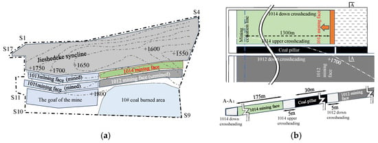
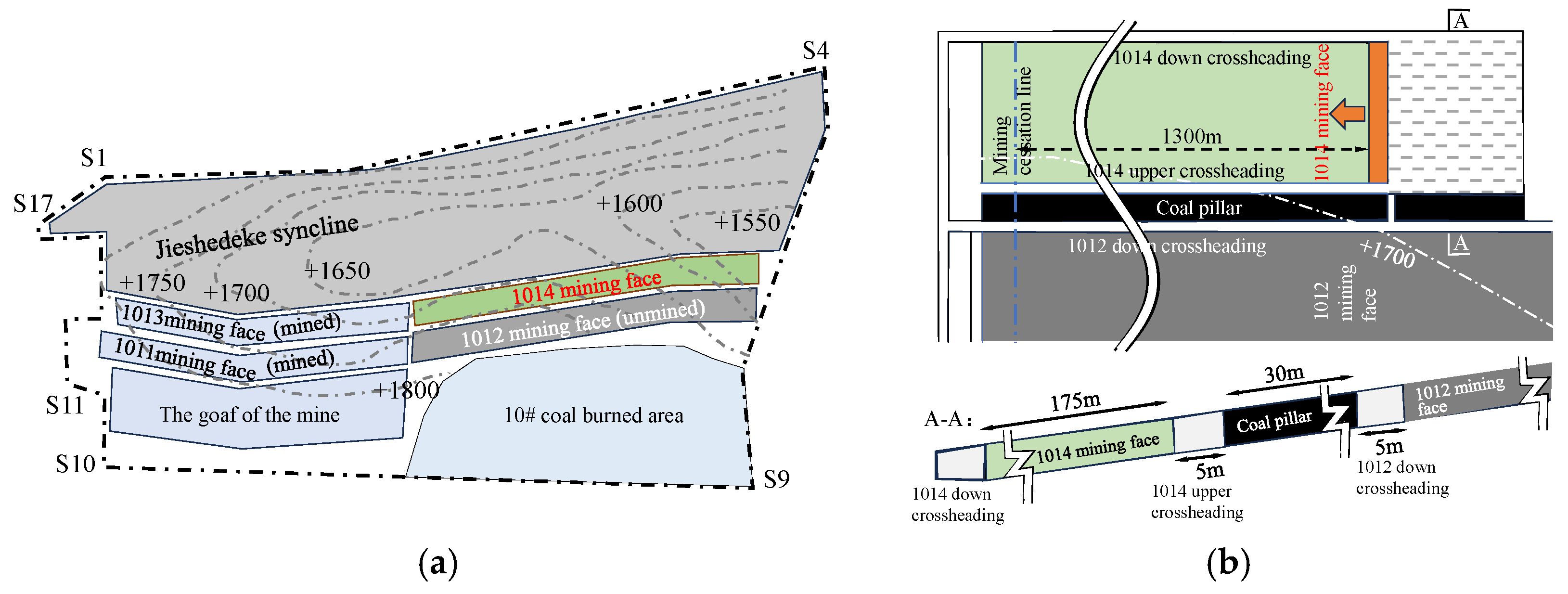
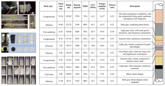
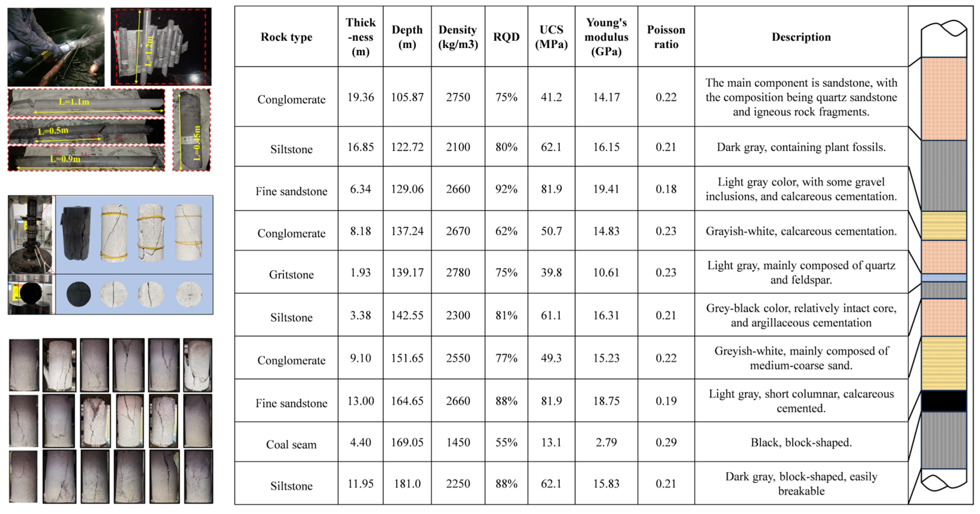
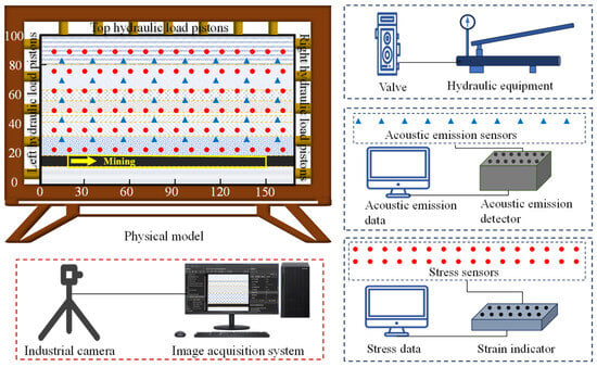
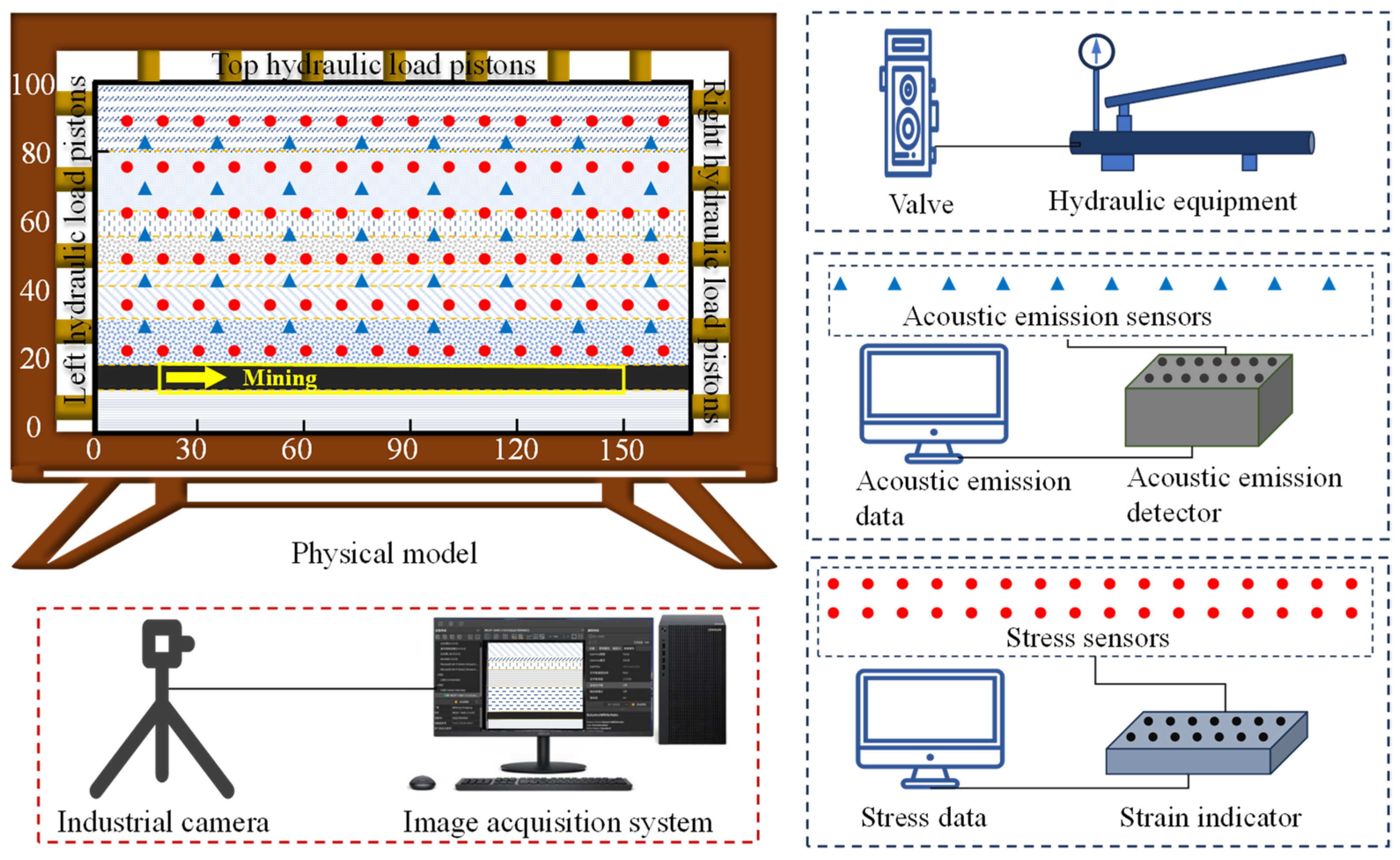
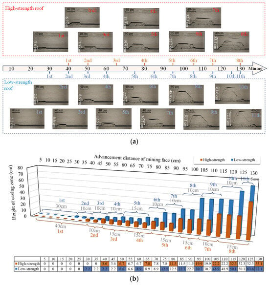
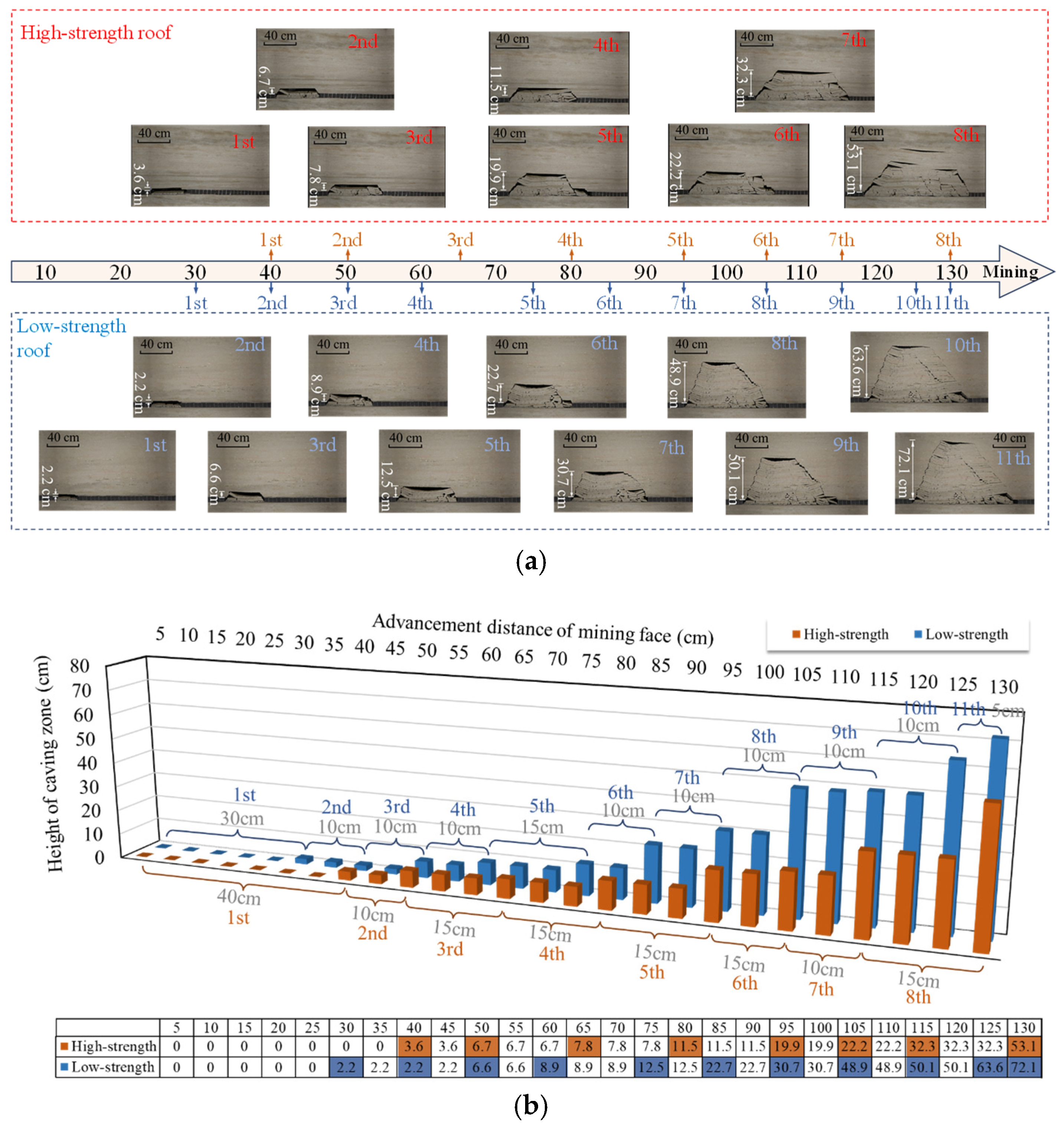
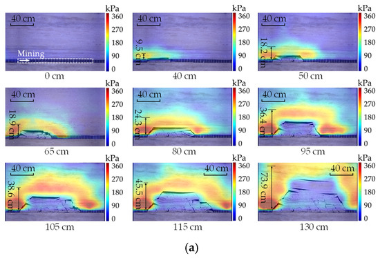
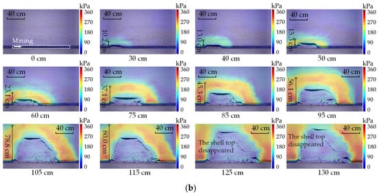
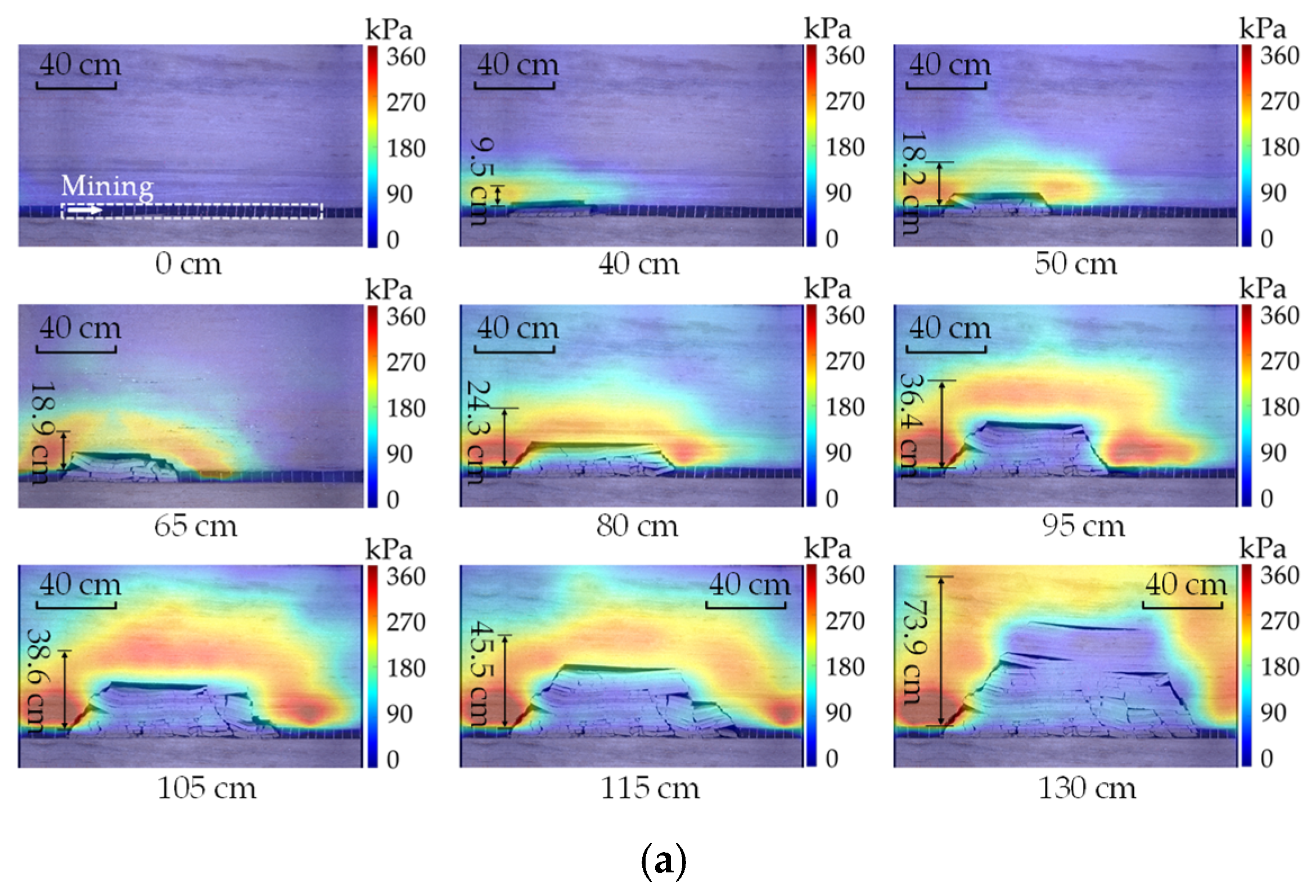
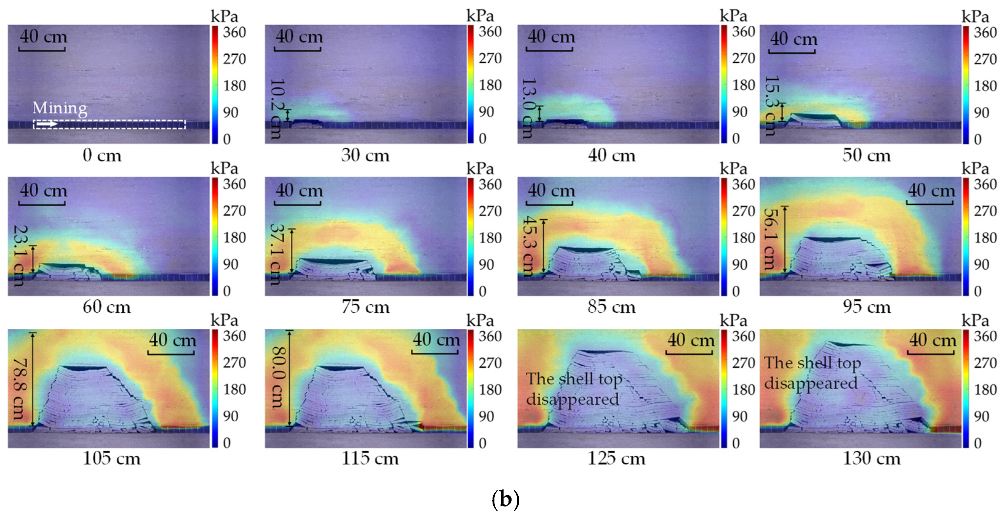
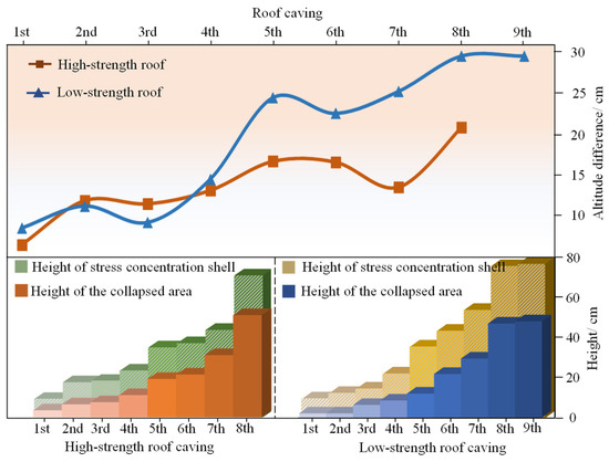
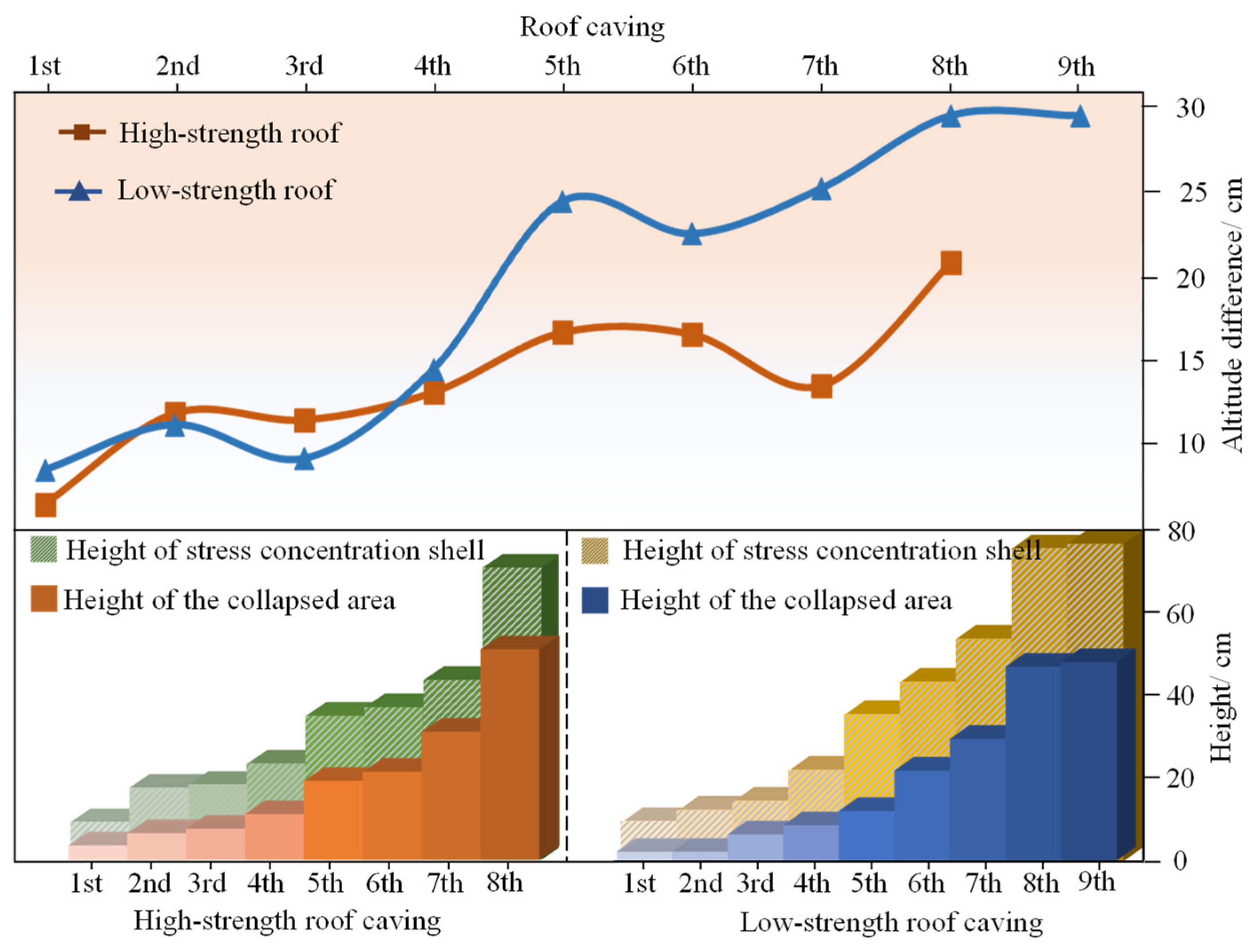
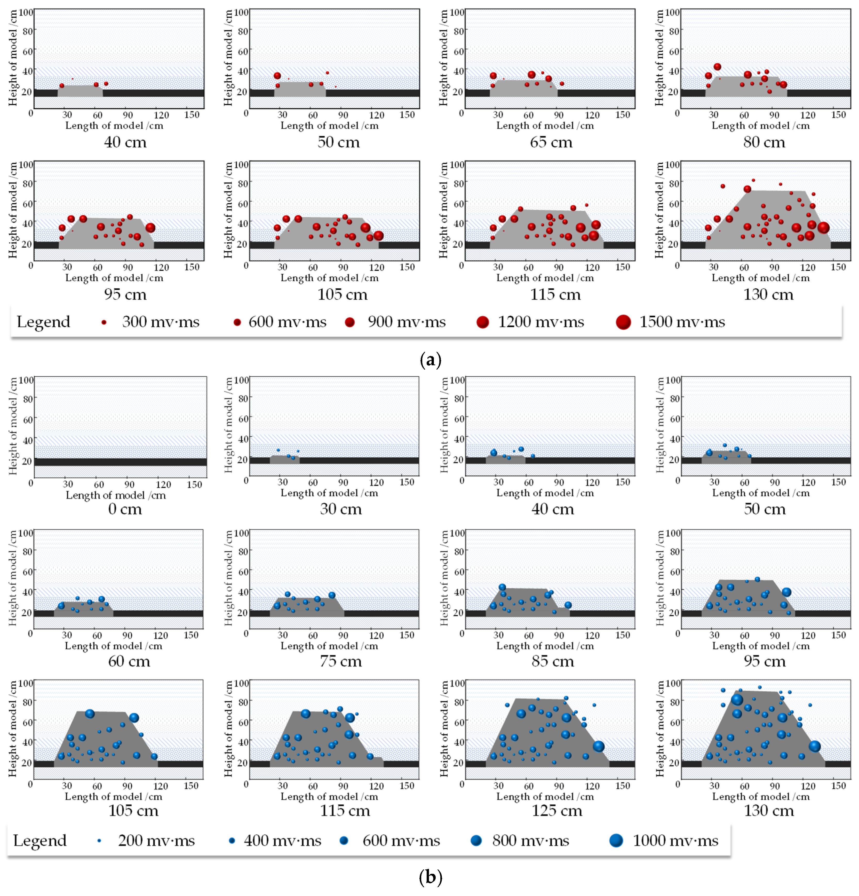
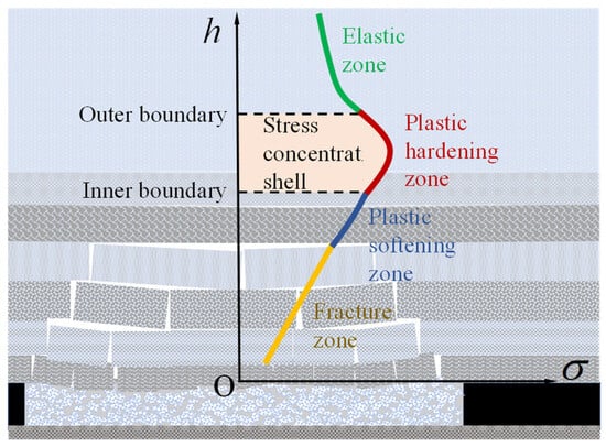
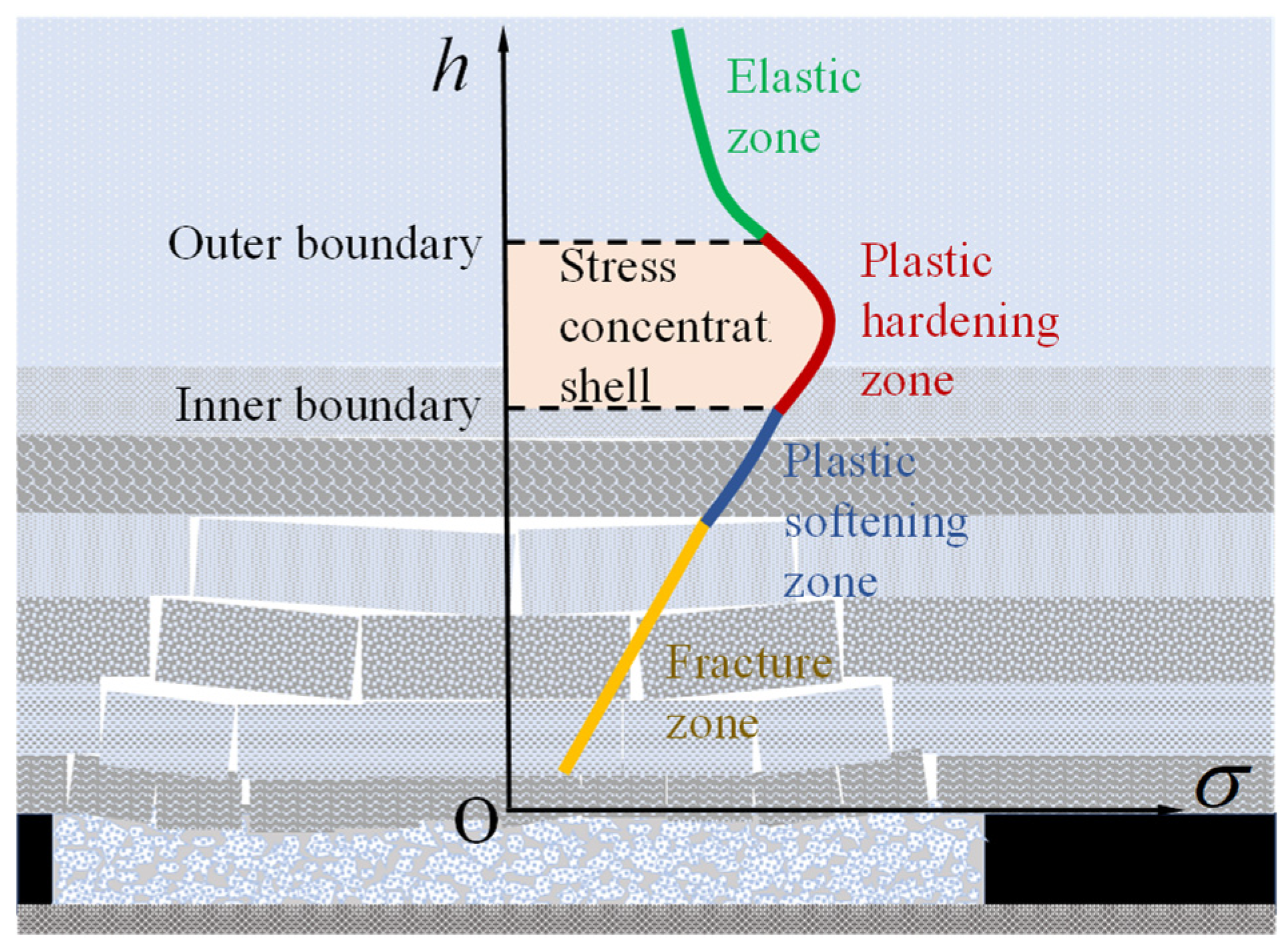
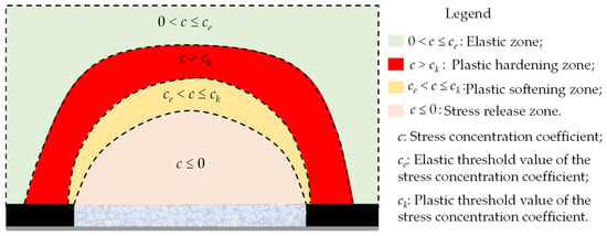
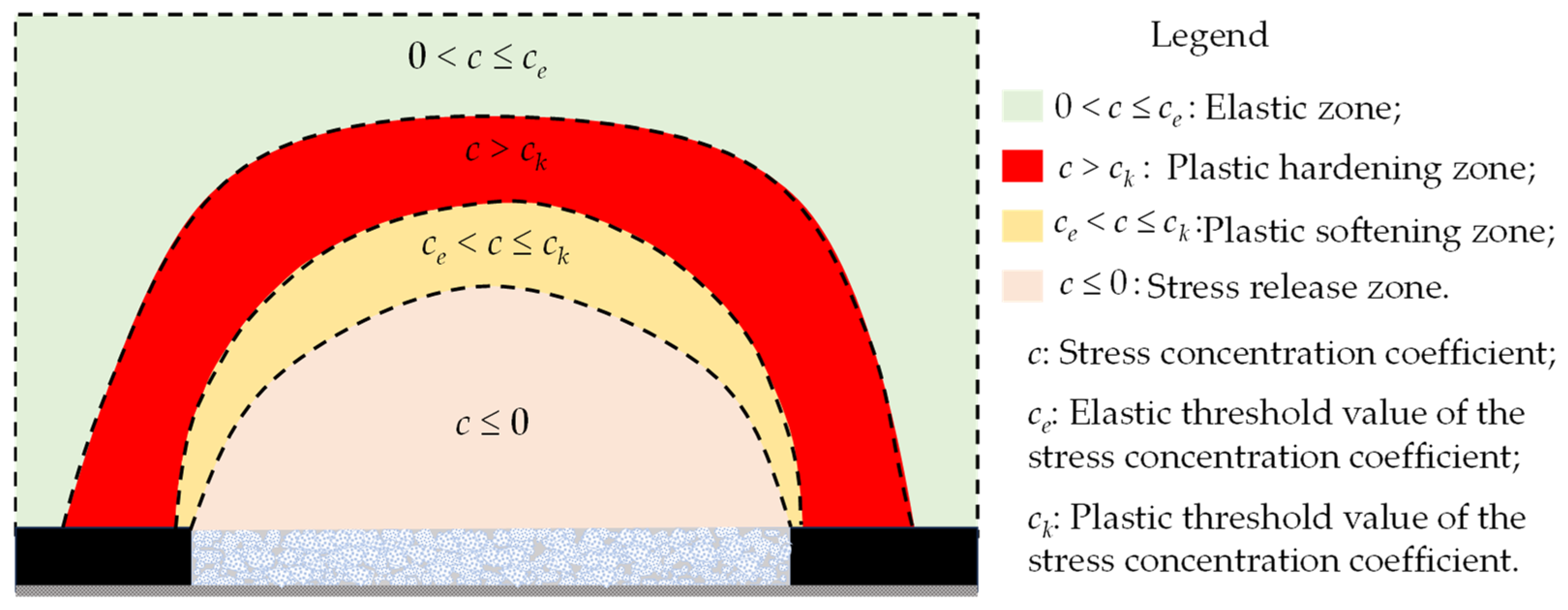
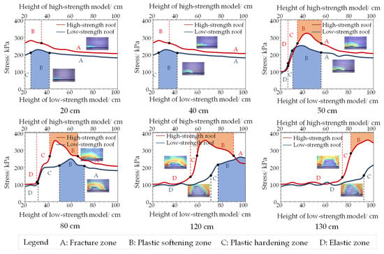
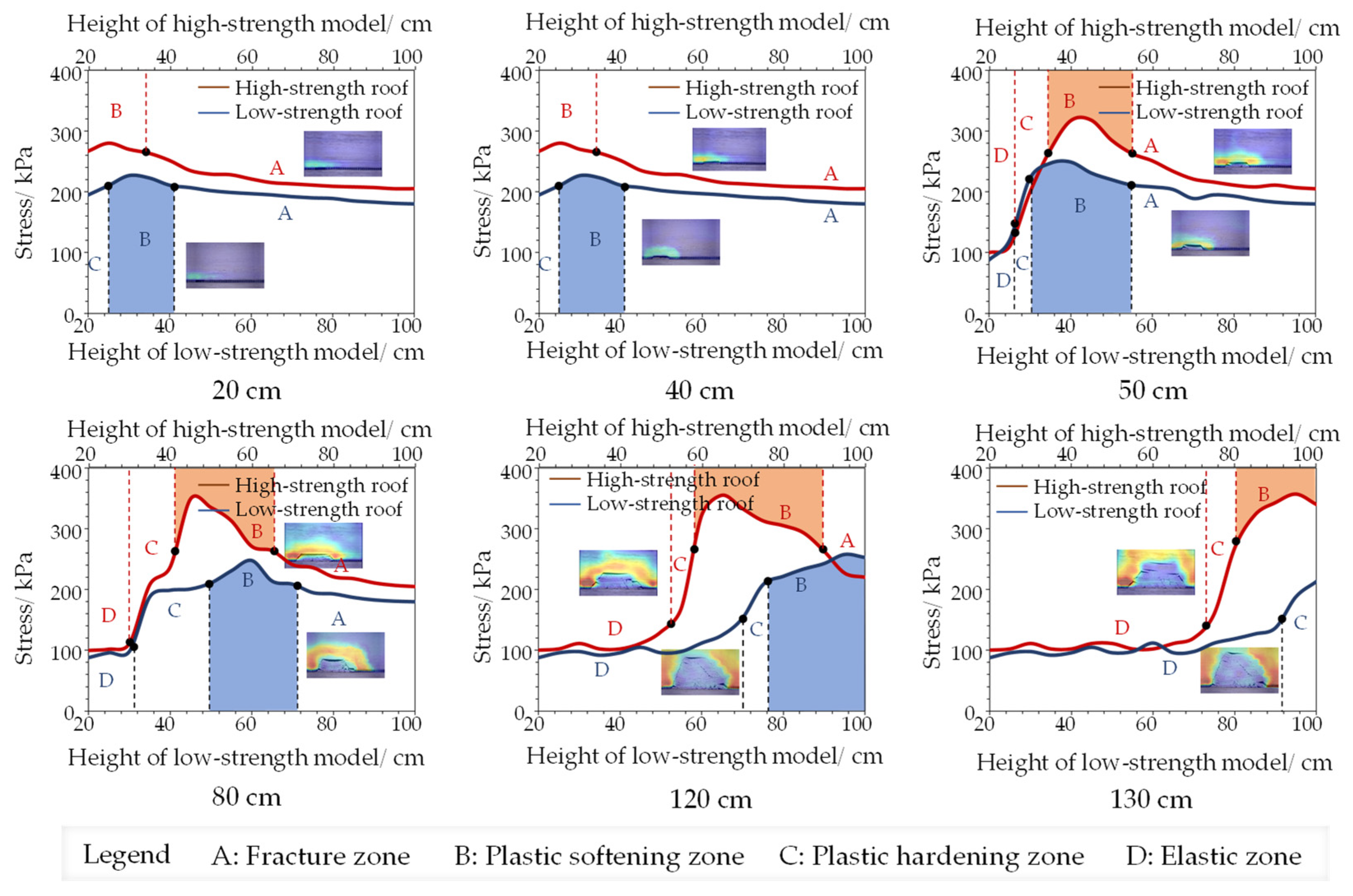
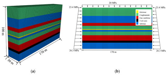
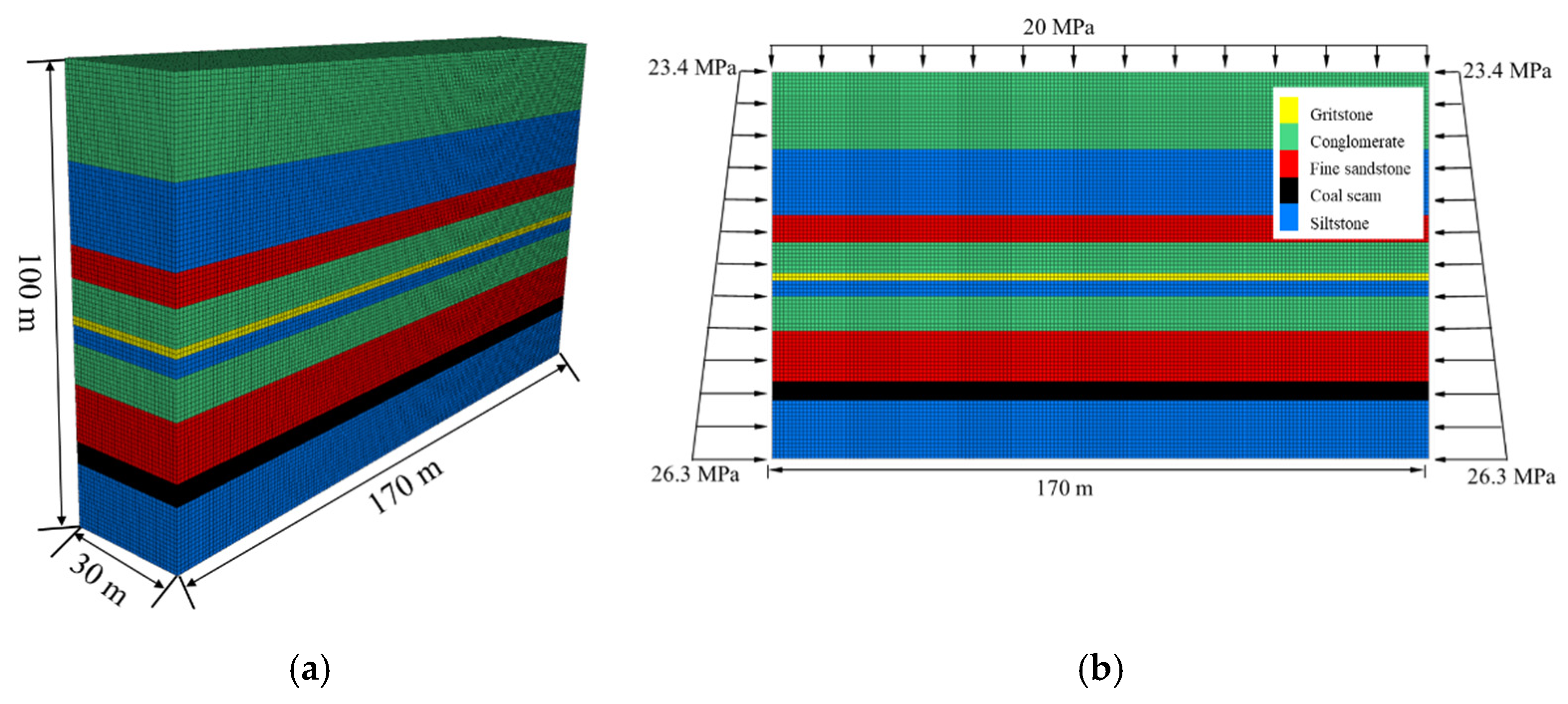
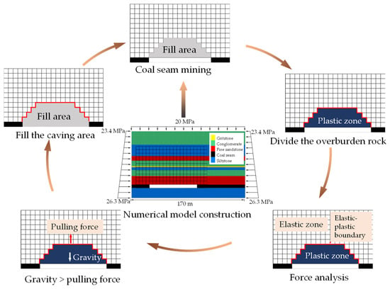
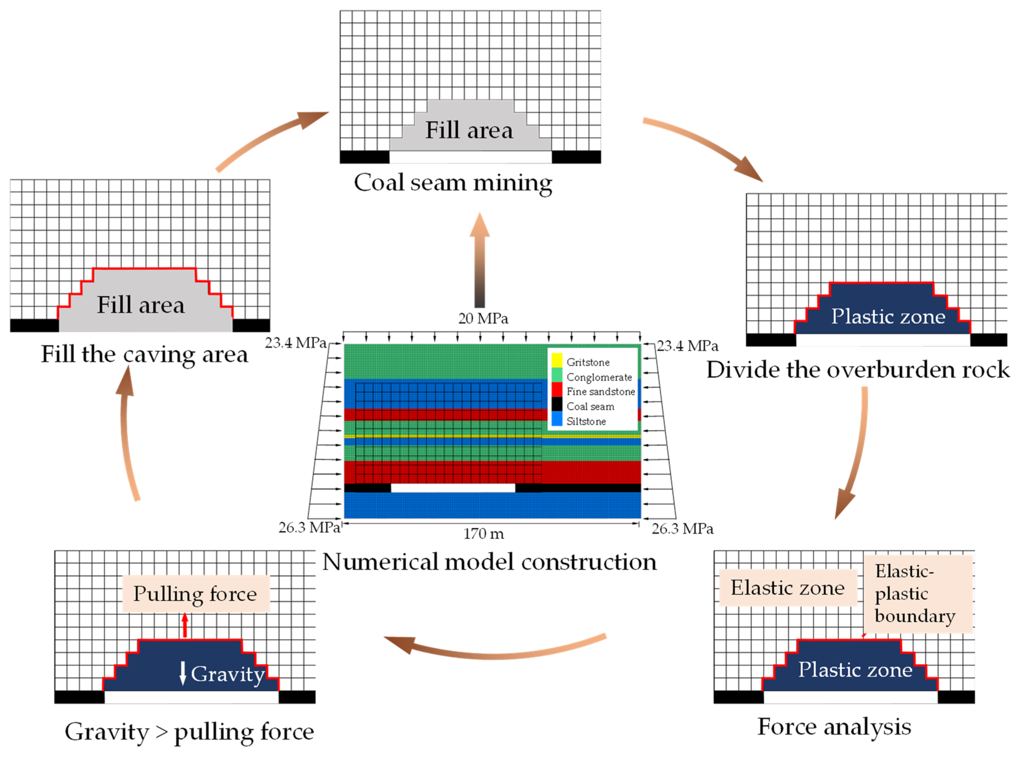
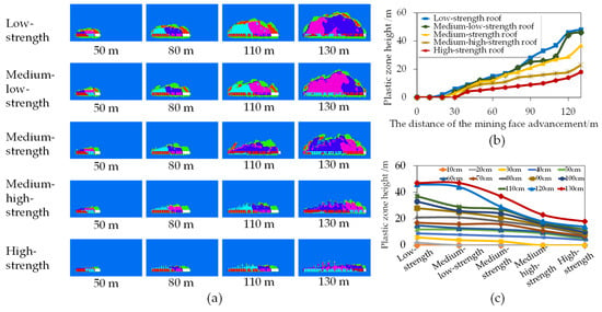
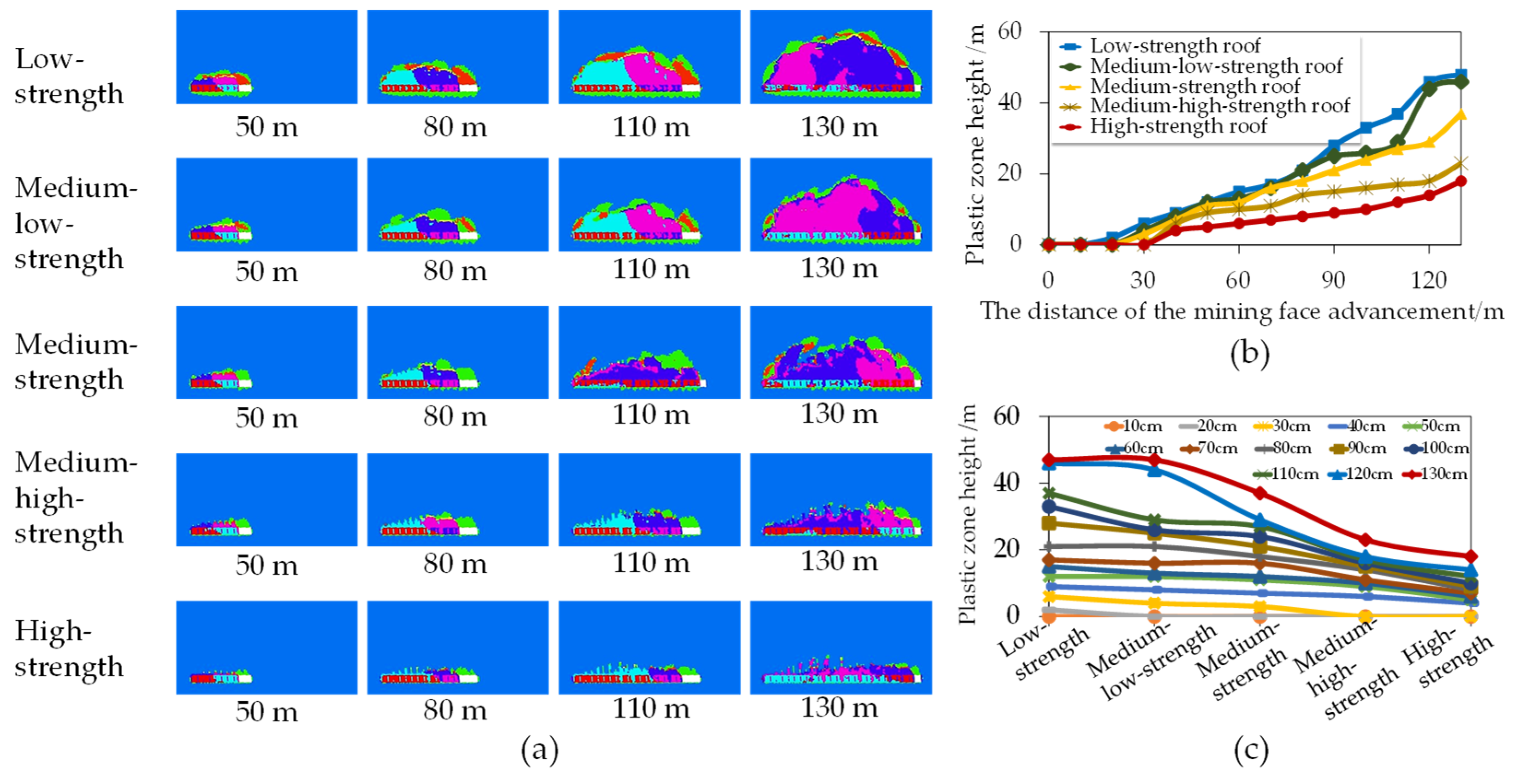
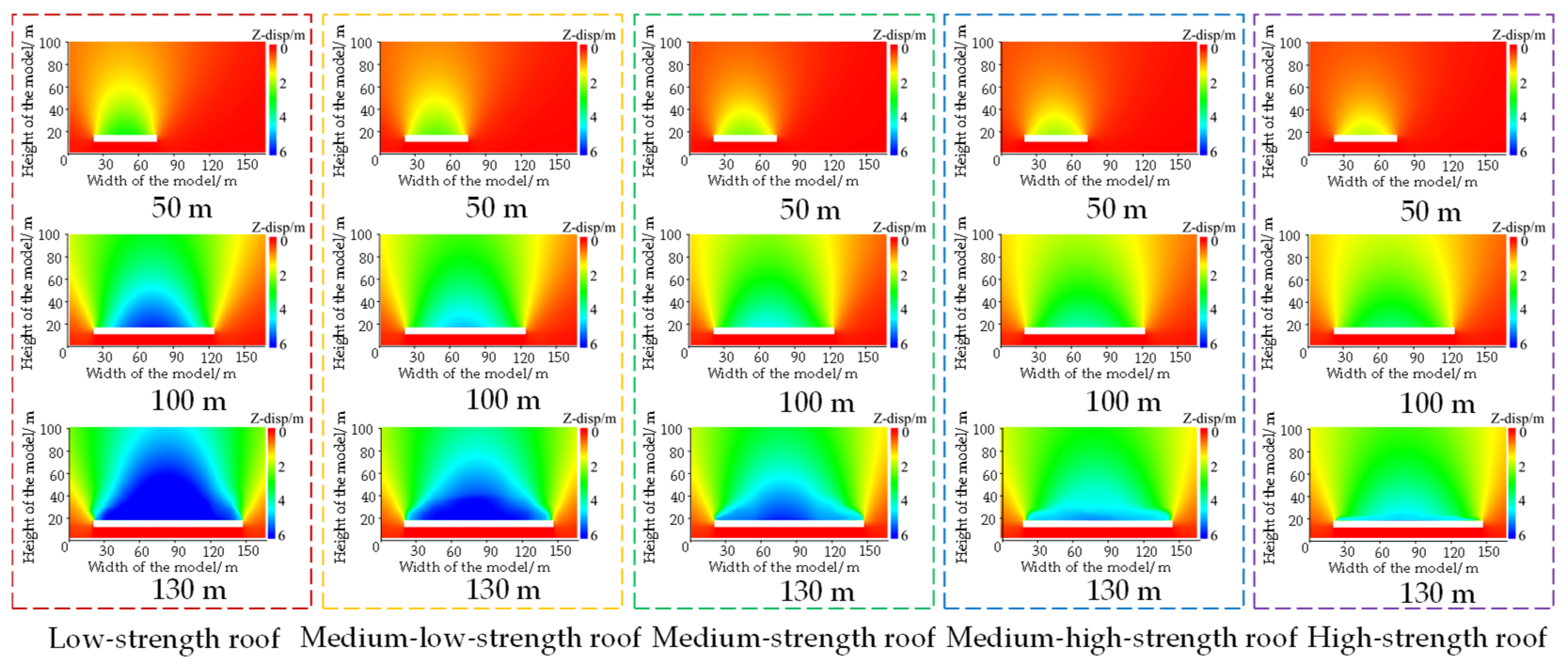
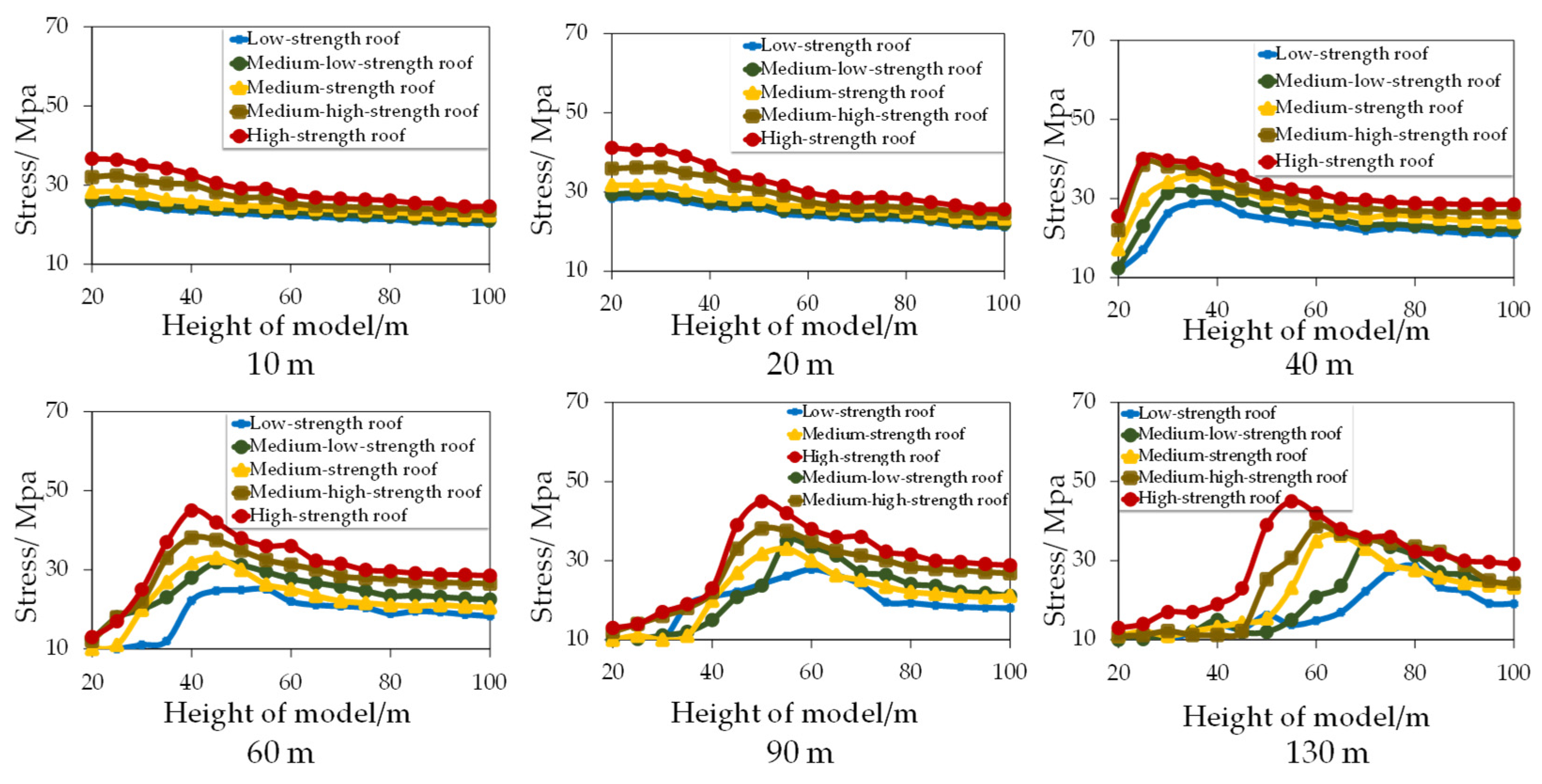



Disclaimer/Publisher’s Note: The statements, opinions and data contained in all publications are solely those of the individual author(s) and contributor(s) and not of MDPI and/or the editor(s). MDPI and/or the editor(s) disclaim responsibility for any injury to people or property resulting from any ideas, methods, instructions or products referred to in the content. |
© 2026 by the authors. Licensee MDPI, Basel, Switzerland. This article is an open access article distributed under the terms and conditions of the Creative Commons Attribution (CC BY) license.