


Abstract
The growing demand for noise reduction in multi-joint long-reach robotic arms necessitates the development of precise noise measurement methodologies. However, accurate characterization remains challenging due to the robot’s complex kinematics. Specifically, dynamic joint positions and motion trajectories can lead to acoustic occlusion, while the inherent directivity of sound sources further compromises measurement reliability. To address these issues, this study proposes a component-based hybrid measurement approach. First, the noise generated by a single joint was characterized using a simplified 4-point method, with Green’s function applied to correct for variable propagation distances. Subsequently, the total sound power level of the entire robotic arm was synthesized in a virtual environment by integrating the single-joint acoustic data with the arm’s operational kinematic program. Validation results demonstrate that the proposed method achieves a measurement error of only 0.8 dB relative to the reverberation chamber benchmark—an accuracy superior to that of direct measurements of the full robotic arm cycle (2.6 dB). Furthermore, a comparison with the ISO 3744:2025 9-point standard method reveals that while the proposed 4-point approach yields a slightly larger error (0.8 dB vs. 0.2 dB), it significantly reduces experimental complexity. Consequently, this method offers a sufficiently accurate and operationally efficient solution for practical engineering applications.
1. Introduction
The multi-joint robotic arm, one of the typical collaborative robots, is widely used in manufacturing, hospitals, and other scenarios that require human–robot collaboration. The running noise of collaborative robots has raised complaints and concerns. Accurate measurement is essential for noise assessment and control, yet applicable methods for measuring noise from such robots are lacking.
In recent years, increasing attention has been directed toward the characterization of motion, vibration, and acoustic phenomena in robotic systems, particularly in collaborative robots and human–robot interaction scenarios. Kim et al. developed and experimentally validated wireless motion gauges for two collaborative robot arms, providing an effective solution for motion measurement and performance evaluation [1]. Knežević et al. demonstrated an automated sound intensity measurement approach by integrating a robotic platform with a sound intensity probe, highlighting the feasibility of robotic platforms in acoustic inspection and measurement tasks [2]. Ahn et al. proposed a three-dimensional acoustic ranging framework to realize both human–robot and robot–robot sound interaction in audible and inaudible frequency bands, extending the application of acoustics in robotics from passive measurement to active interaction [3]. In virtual collaboration scenarios, Sievers et al. investigated soundscape generation for virtual human–robot collaboration, emphasizing the importance of auditory scene design in enhancing immersion and realism [4]. Cernohlavek et al. conducted vibration measurements on a six-axis collaborative robotic arm, contributing to the understanding of its dynamic response and operational characteristics [5]. More recently, Wessels et al. examined the auditory localization and perceptual assessment of consequential robot sounds in virtual reality, providing insights into how robot-generated sounds are spatially perceived and cognitively evaluated by human users [6]. Collectively, these studies indicate that research on collaborative robots is moving beyond conventional motion analysis toward a more comprehensive investigation of vibration behavior, acoustic emission, and auditory perception. While these studies have deepened our grasp of robot acoustics and dynamics, the industry still lacks accessible and standardized protocols for accurately quantifying the sound power level (SWL) of multi-joint collaborative robots in practice.
In the field of machinery noise measurement, test objects vary substantially across sectors, ranging from fluid-moving and rotating machinery to construction equipment, household appliances, and information technology (IT) hardware. Despite this diversity, the methodology follows a shared backbone: the SWL is universally used as the comparable descriptor of a machine’s intrinsic airborne noise emission, with basic standards providing the measurement framework. Under controlled conditions approximating a free field over a reflecting plane, SWL is typically determined using the engineering sound-pressure method over an enveloping surface (ISO 3744) [7]. When controlled facilities are not feasible and sources must be assessed in situ within reverberant environments, a survey approach using a calibrated reference sound source is applicable (ISO 3747) [8]. Alternatively, sound intensity methods are often preferred when high background noise or reflections complicate sound-pressure measurements (ISO 9614-1) [9]. Building upon these fundamental methods, specific equipment families adopt noise test codes that prescribe precise operating conditions, installation, and loading requirements to ensure reproducibility. Examples include standards for compressors and vacuum pumps (ISO 2151) [10], earth-moving machinery (ISO 6393) [11], and ducted fans where in-duct acoustic power is characterized (ISO 5136) [12]. Similarly, domains such as household appliances (IEC 60704-1) [13] and IT/telecommunications equipment (ECMA-74) [14] standardize measurement and procedures to minimize inconsistencies arising from divergent test practices.
A national standard (i.e., GB/T 37242:2018) obtained the radiated sound power level (SWL) of noise emitted by stationary industrial robots with four microphones at fixed positions measuring the sound pressure level (SPL) in the semi-free sound field [15]. The standards usually require the sound source to remain stationary and free from obstructions between the source and the microphone in the semi-anechoic chamber [7,16]. This method proposed in the national standard remains a subject of discussion for collaborative robots that exhibit strong non-stationary acoustic characteristics, as each noise source (i.e., the joint) has distinct temporal and spatial trajectories during operation. The reverberation chamber can overcome the above shortcomings in measuring the SWL of the collaborative robots because of its uniform energy density during the machine’s running period [16]. Still, measurement in the reverberation chamber is not applicable in practice due to the high cost and strict requirements on the temperature and humidity. Accurate noise measurement of multi-joint robotic arms in semi-anechoic chambers or quiet factory environments is still a widespread requirement in engineering.
Previous studies have typically employed specialized microphone arrays to characterize noise from non-stationary sound sources. For instance, standardized ground-level microphone configurations have been utilized to capture wind turbine noise under time-varying conditions [17]. Alkmim et al. adopted a hemispherical array to measure the non-stationary emissions of a quadrotor drone [18], while roadside microphone setups have been applied to quantify noise from accelerating vehicles [19]. Collectively, these studies underscore that for non-stationary sources, it is crucial to capture acoustic radiation over the entire operating cycle using appropriately distributed sensors. In practice, the noise level is often represented by time-averaging the SPL over a complete cycle and aggregating data from multiple microphones.
However, multi-joint collaborative robots present a unique challenge: the source–microphone distance varies continuously due to the arm’s spatial trajectory. This relative motion induces time-varying SPL fluctuations, complicating the estimation of SWL. Similar dynamic effects have been noted in other moving-source contexts, such as UAS [20]. Consequently, approaches that integrate spatial or pose information into sound power estimation [21] provide valuable references for compensating for distance variations and improving measurement repeatability.
The distance between the noise sources and microphones varies with the space trajectory of the robotic arm, leading to varying SPL during the noise measurement that affects the accuracy of SWL results. From previous studies, the accurate SPL seems to be calculated using Green’s function with the known space positions of the joints and the microphones. For example, Xiong et al. used the point source to estimate the sound power of three loudspeakers through Green’s function [22]. Gao et al. obtained the SPL of the noise sources at a specific position using Green’s function between noise sources and microphones [23]. Okoyenta et al. used the free-space Green’s function of stationary and rotational sources to calculate the sound pressure at any point away from the source [24]. From above, the SPL at each moment could be estimated by Green’s function with recorded data and the distance between the noise sources and microphones during the measurement.
Robotic arms executing complex spatial trajectories can physically obstruct the sound propagation path between a noise-emitting joint and a microphone, resulting in artificially attenuated SPL readings [25]. For example, during the operation of a six-joint industrial robot, the coordinated movement of multiple links frequently positions the arm between the noise source and the sensor. This acoustic occlusion, combined with the inherent directivity of the sound source, significantly compromises measurement accuracy and limits the effectiveness of point selection protocols stipulated in standards such as GB/T 37242:2018 [15].
To address such data corruption, interpolation is a commonly used approach for estimating missing or uncertain samples from neighboring observations [26]. Interpolation-based strategies have been widely applied in acoustics and structural dynamics, such as introducing weighting coefficients to mitigate discontinuities in frequency-domain impedance [27], reconstructing transient acoustic fields via time-domain equivalent source methods [28], and estimating unmeasured vibration velocities from sparse surface data [29]. In principle, SPL samples corrupted during obstructed moments could similarly be approximated from adjacent, unobstructed time instants. In this study, however, the focus is on refining the measurement setup to physically minimize the occurrence and influence of acoustic obstruction. Consequently, interpolation is considered only as an optional post-processing tool, which may become unnecessary once the improved measurement configuration is adopted.
While the ISO 3744:2025 standard [7] employs a dense array of measurement points to ensure accuracy, particularly for sources with strong directivity, implementing such extensive setups is often impractical in industrial environments. Addressing the critical need for a method that balances high accuracy with a minimized measurement set, this study proposes a novel approach for determining the SWL of multi-joint collaborative robots in a semi-anechoic chamber. To mitigate the effects of complex temporal and spatial trajectories, we introduce a specific three-step solution: (1) characterizing the acoustic emissions of the robotic arm during single-joint operations; (2) applying Green’s function to compensate for the dynamic distance variations between joints and microphones; and (3) performing a weighted summation of acoustic energy based on the operation cycle of each individual joint. The accuracy of this method was subsequently validated against benchmark results obtained in a reverberation chamber.
2. Materials and Methods
2.1. Data Acquisition
2.1.1. Apparatus
Semi-Anechoic Chamber
The dimensions of the semi-anechoic chamber are 8.4 m × 6.2 m × 4.8 m (length × width × height), with a free-field frequency range of 100 Hz to 10 kHz, and a background noise level of 15.6 dB (A).
Measurement devices
Four microphones (BK 4948, Brüel & Kjær, Nærum, Denmark) were connected to the data acquisition system (BBM MKII, Müller-BBM GmbH, Planegg, Germany) to record the signals. All microphones are calibrated using a BK 4231 calibrator (Brüel & Kjær, Nærum, Denmark) at a reference level of 94 dB SPL.
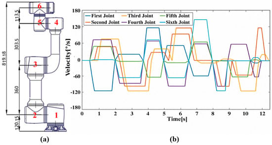
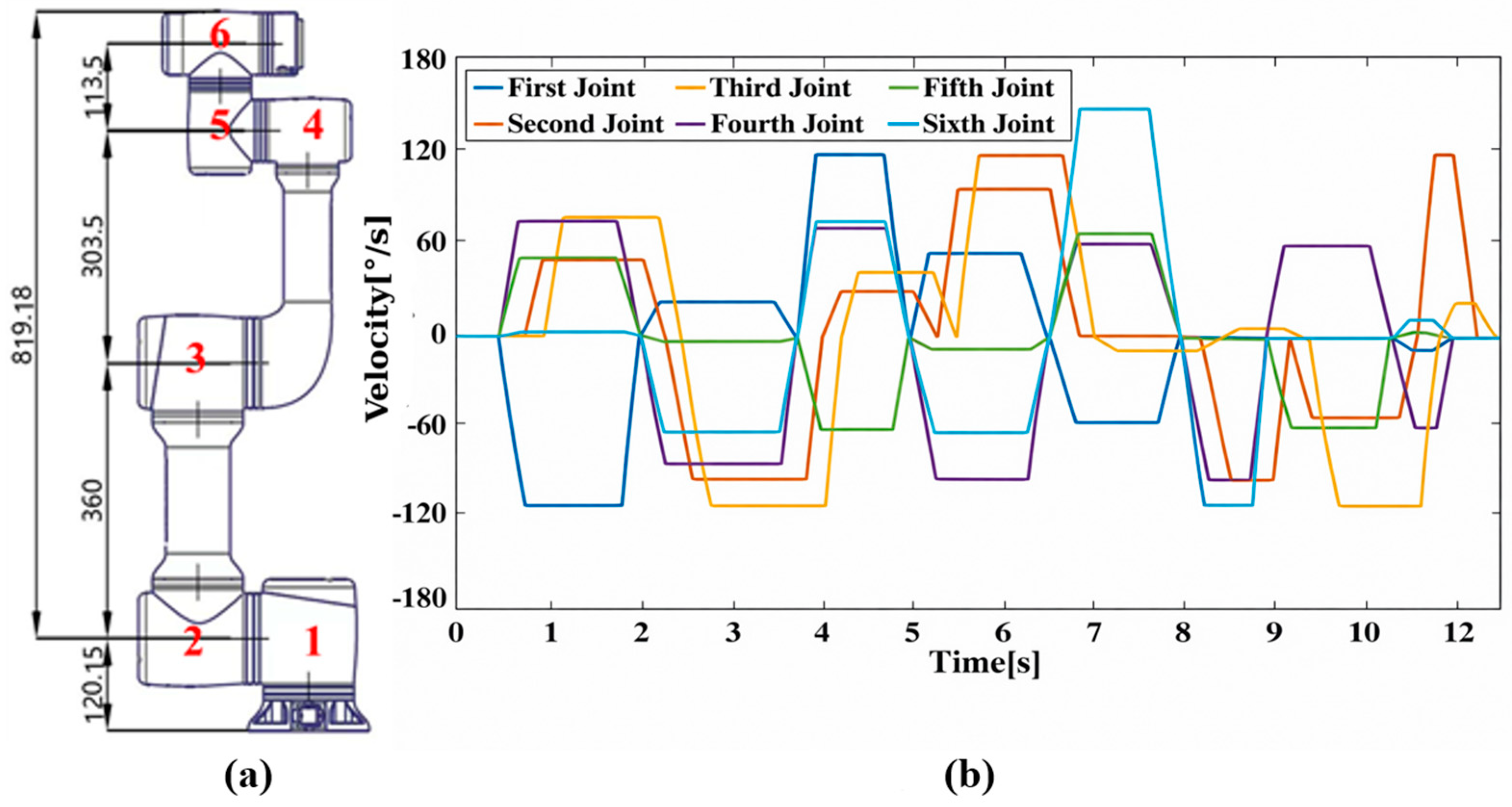
The measurement objective is a JAKA Zu7 (JAKA Robotics, Shanghai, China) series collaborative robot that features six joints. The primary dimensions of its joints and arms (mm) are depicted in Figure 1a. Table 1 provides a detailed list of the motion range and velocity for each joint and entire robotic arm.
Figure 1.
The measurement setup. (a) Collaborative robotic arm in millimeters; (b) Operational logic of the robotic arm.
Table 1.
Motion Range and velocity of each joint.
2.1.2. Procedure
Measurements were conducted in the semi-anechoic chamber. The sampling rate was set at 44,100 Hz.
The SPLs of the individual joint operation were measured according to the operational logic outlined in Table 1. The operation of the entire robotic arm is orchestrated by the simultaneous movement of its individual joints, each following distinct cycles, as shown in Figure 1b. Within the semi-anechoic chamber, the SPL of each independently running joint and the entire cycle involving all six joints was measured sequentially. During tests, the operating cycles of individual joints are around 4 s for Joints 1, 5, and 6; and 2 s for Joints 2 to 4, and the operating cycle of multiple joints is 12 s for the entire system. To encompass at least two complete operating cycles, the measurement durations were established at 10 s for the individual joint analysis and 30 s for the system. In the subsequent analysis, the data was derived by averaging the values recorded over two cycles.
2.2. Layout of Measuring Points
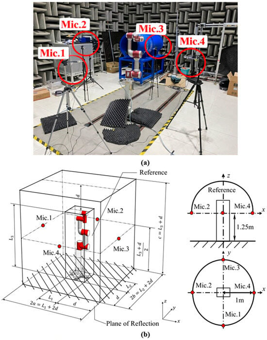
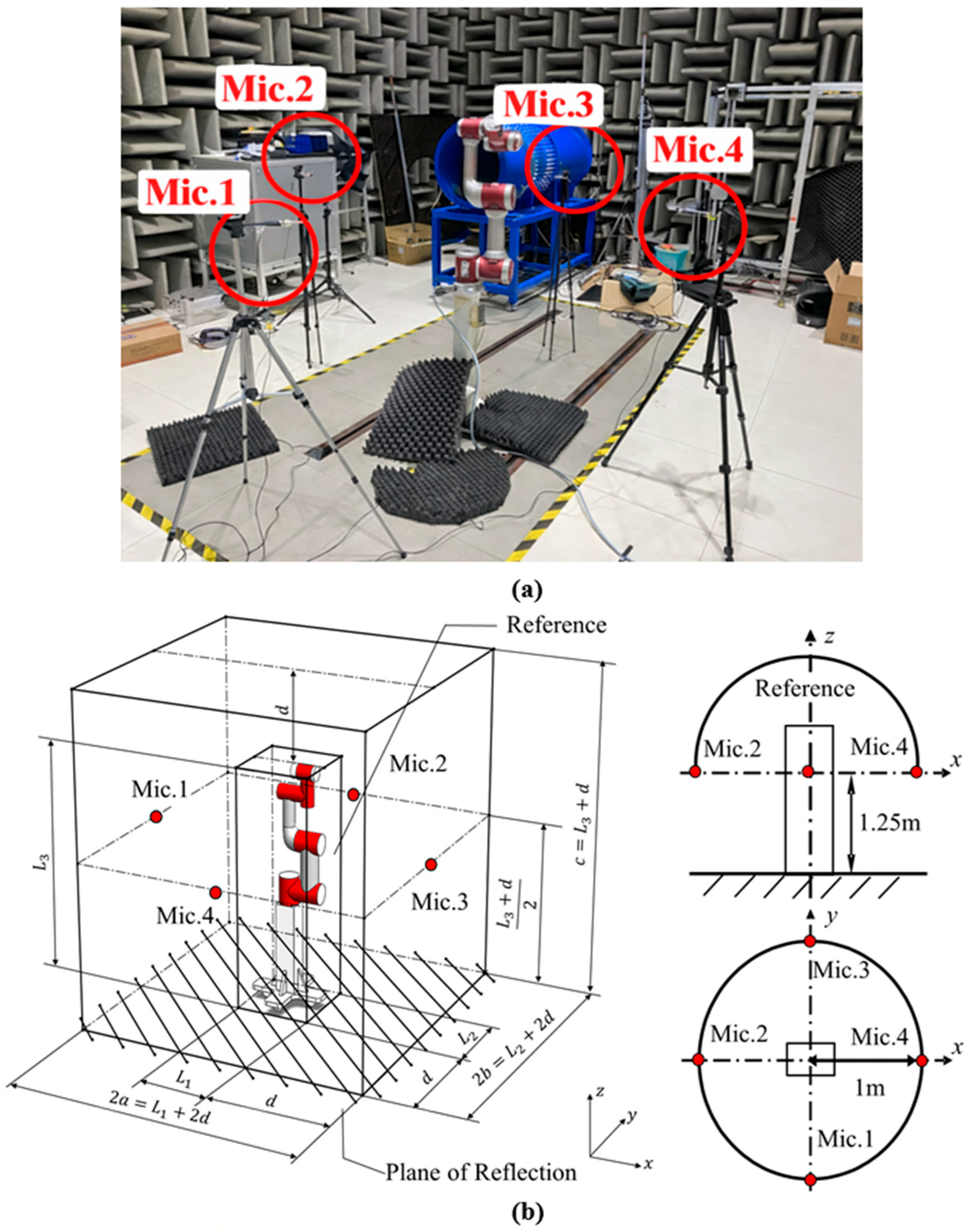
According to ISO 3744:2025 standard [7], the reference body is defined as an imaginary closed surface composed of the smallest cube that can completely enclose the measured sound source. This surface is used to define the layout range of the measuring microphone and the measurement area, thereby unifying the noise testing methods under different equipment and different measurement conditions. In our measurement process, the reference body was defined as the smallest rectangular parallelepiped enclosing the robotic arm in the pose shown in Figure 1a. Four measuring points(“Mic.” is the abbreviation for “microphone”) were arranged on the rectangular envelope surface of the robot’s front, back, left and right, respectively, as illustrated in Figure 2b. These points were positioned along the central symmetry axis, with a horizontal distance of 1 m from the datum body and a height of 1.5 m.
Figure 2.
Layout of Four Measuring Points. (a) Layout of the semi-anechoic chamber; (b) Schematic of the measurement points.
2.3. Data Analysis
2.3.1. SWL Calculation
The average A-weighted SPL in an indoor testing chamber can be determined using the following equation:
where is the average A-weighted SPL, is the number of measurement points, is the A-weighted SPL at the th measurement point, and is the background noise correction factor [15].
According to GB/T 37242:2018 standard [15], the SWL is calculated in Equation (2):
where envelops the surface area of the measured sound source.
2.3.2. Correct SPL of Semi-Anechoic Chamber
During single-joint measurement, the distances between each joint and the microphone are different, leading to inaccurate noise signal measurements. Corrections are applied to the SPL measured in the semi-anechoic chamber to address this issue.
To account for the varying distances between the joints and the microphones, Green’s function is employed to normalize the acoustic data to a 1 m reference. While we acknowledge that the robot joints exhibit distinct directionality and are not strictly ideal monopolar sources, this approximation provides a functional baseline for practical measurement. Accordingly, the time-domain wave equation can be expressed as:
where is the speed of sound; is the sound pressure at position and time ; is monopole strength at position and time .
After performing the Fourier transform on Equation (3), the frequency-domain wave equation can be expressed as:
where is wave number, and is the circular frequency of the simple harmonic vibration of the sound source.
By approximating the joint as a single monopole sound source, the corresponding acoustic wave equation can be expressed as:
where denotes the position of the microphone measurement, and signifies the positions of the joints of the robotic arm.
The Green function, which is the solution to Equation (5), is given by:
Consequently, the distance correction can be carried out using Equation (7):
where is the spectral content of the sound pressure signal at positions (i.e., microphone measurement positions); and is the spectral content of the sound source signal at positions (i.e., the positions of individual joint of the robotic arm).
2.3.3. Calculation of the SPL of the Entire Robotic Arm
Due to the complex operating conditions and numerous obstructions of the entire machine, and the more controllable operating conditions of the single joint, the virtual working condition method is adopted for calculation. This method first calculates the A-weighted SPL of the single joint operating condition separately, and then directly obtains the A-weighted SPL of the entire machine based on the operating time of each joint, and subsequently calculates the SWL of the entire robotic arm.
Applying the principle of acoustic energy equivalence, the overall A-weighted SPL of the robotic arm is estimated by superimposing the contributions of individual joints, as defined in Equation (8):
where is the average estimated A-weighted SPL of all measurement points, is the index of individual joint, is the total number of joints, donates the running duration of the th joint, and is the SPL during the single-joint operation of the th joint.
Analogous to Equation (2), the total SWL of the entire robotic arm is calculated according to the GB/T 37242:2018 standard [15], as shown in Equation (9):
where is the estimated A-weighted SWL; is the average estimated A-weighted SPL of all measurement points; envelops the surface area of the collaborative robot.
2.4. Validation Experiment in Reverberation Chamber
The validation experiment was conducted within a reverberation chamber with dimensions of 5.4 m × 6.8 m × 8.6 m (length × width × height), characterized by three mutually perpendicular internal surfaces equipped with diffusers. Throughout the testing period, the room temperature fluctuated between 20 °C and 23 °C, and the sound speed was presumed to be 343 m/s.
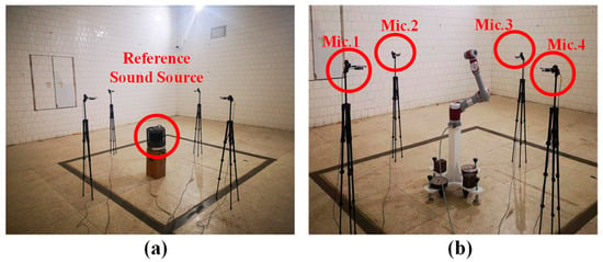
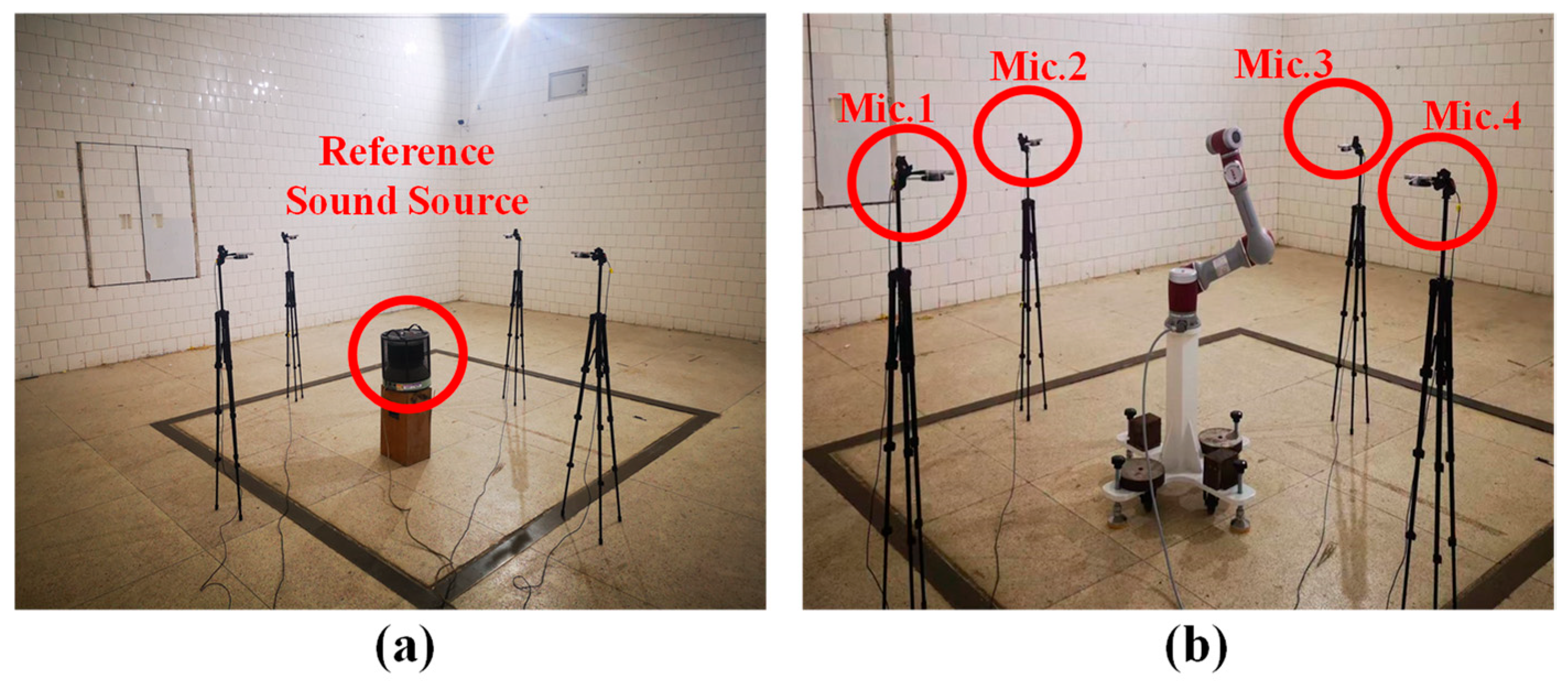
In the reverberation chamber, the measurement setup was meticulously maintained to be consistent with that of the semi-anechoic chamber (refer to Figure 1). The SWL of the robot was determined using the comparison method. A reference sound source compliant with ISO 3741:2010 standard [30], boasting a sound power output of 91 dB and a frequency range from 100 Hz to 20 kHz, was employed. Initially, the SPL of the reference sound source is measured, as illustrated in Figure 3a. Subsequently, the SPL of the robot was measured, with the robot positioned identically to the reference sound source, as depicted in Figure 3b.
Figure 3.
The validation experiment setup (a) Arrangement of reference sound sources; (b) Reverberation chamber layout.
In accordance with the ISO 3741:2010 standard [30], the SWL of the sound source is determined via a comparative method, utilizing a reference sound source with a calibrated sound power. This relationship is formulated as Equation (10):
where is the 1/3 octave A-weighted SWL of the measured sound source, and denotes 1/3 octave A-weighted SPL of the standard sound source.
3. Results
3.1. SPL Correction and SWL Calculation of Single Joint
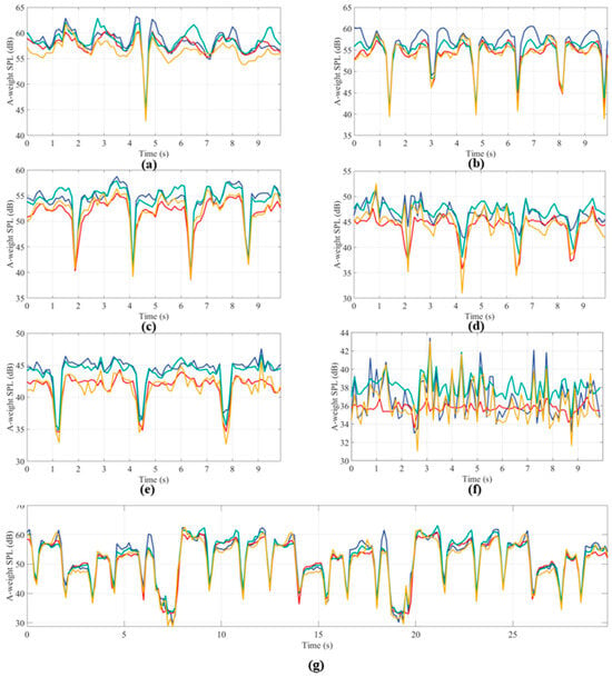
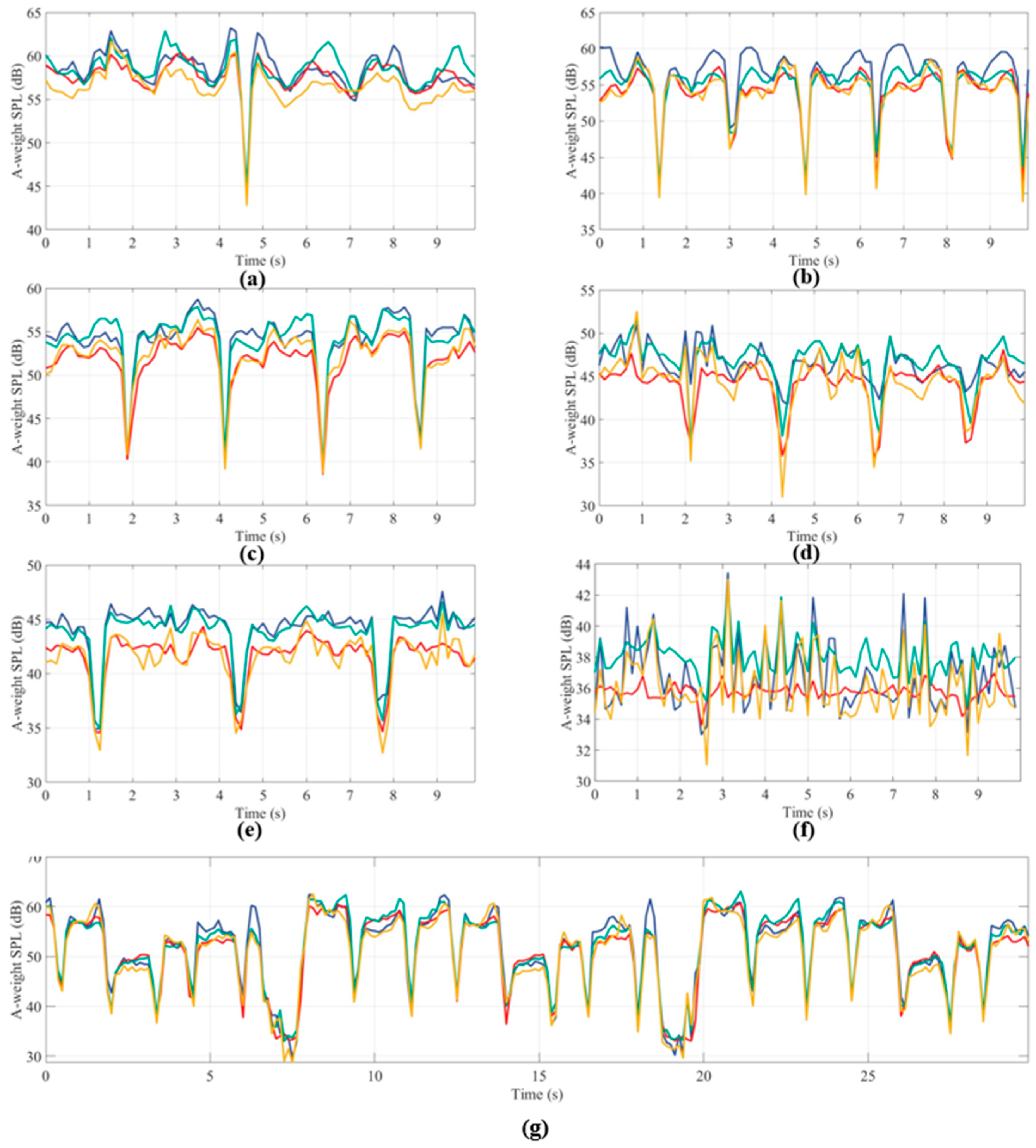
To evaluate occlusion effects, A-weighted time-domain SPLs (0.125 s averaging) were analyzed for individual joints (10 s) and the entire robotic arm (30 s), as illustrated in Figure 4. Despite significant spatial variation between measurement points, temporal SPL fluctuations showed no correlation with the robot’s physical movement. This lack of synchronization indicates that occlusion-induced errors are negligible during single-joint measurements.
Figure 4.
A-weighted time-domain SPL of Single Joint (a) Joint 1; (b) Joint 2; (c) Joint 3; (d) Joint 4; (e) Joint 5; (f) Joint 6; (g) Entire operational cycle of the robotic arm; —point 1, —point 2, —point 3, —point 4.
Table 2 summarizes the average SPLs for each joint across the four measurement points. Notably, points 1 and 3 consistently recorded higher levels than points 2 and 4. While the temporal profiles in Figure 4 remain synchronized across all positions, a persistent spatial variance of 2–3 dB was observed among the average levels. This discrepancy confirms that the noise emitted by the source exhibits distinct directionality.
Table 2.
The A-weighted average SPLs of the six joints running separately at each of the 4 measurement points (dB).
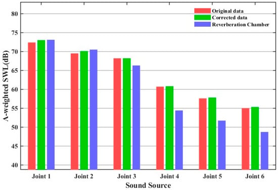
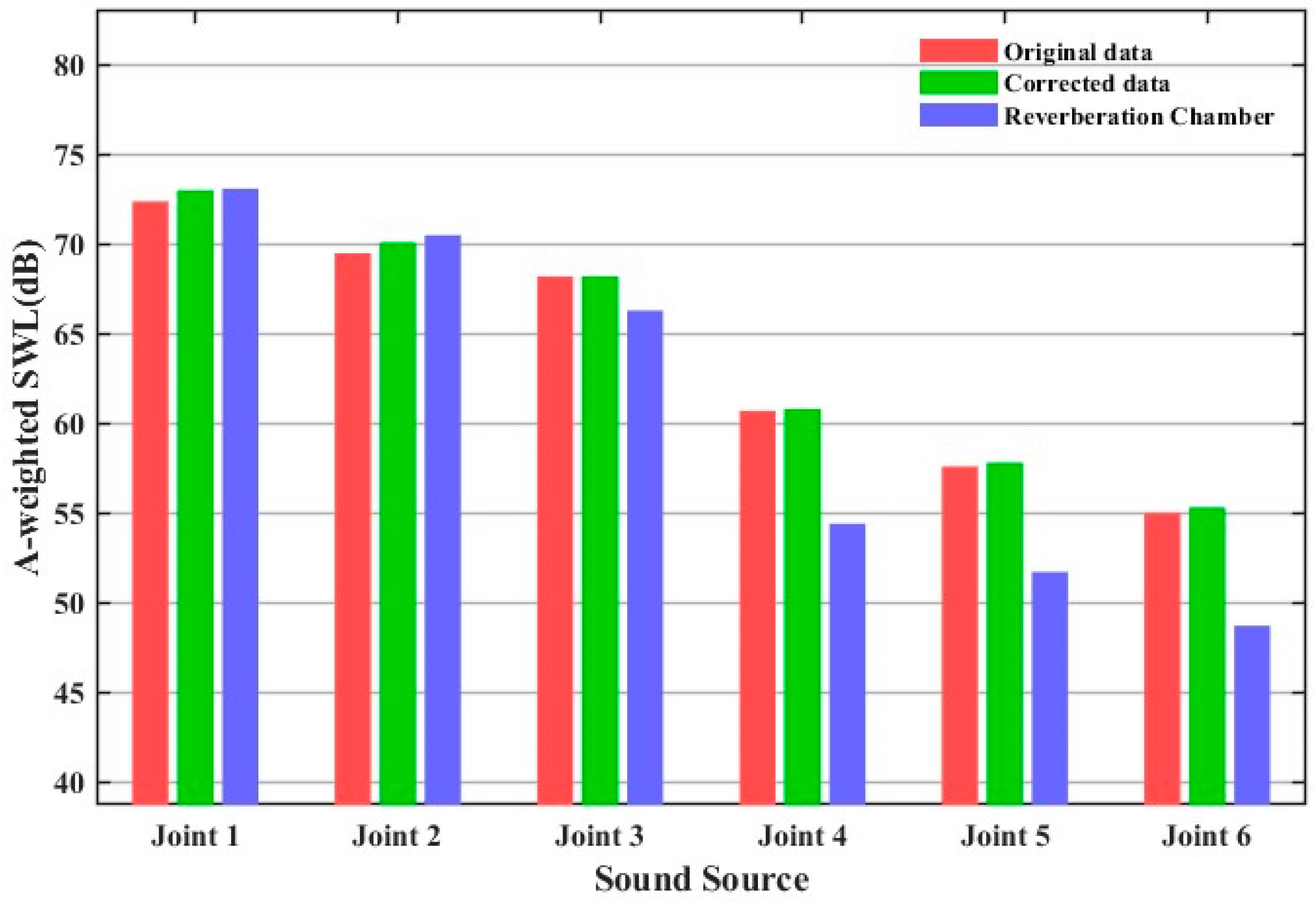
SPL analysis identifies Joints 1–3 as the dominant noise sources. To account for varying source-to-microphone distances during operation, SPL data were normalized to a 1 m reference using Equation (7). Single-joint SWLs, both pre- and post-correction, were then calculated via Equations (1) and (2) and benchmarked against reverberation chamber data (Table 3; Figure 5).
Table 3.
SWLs of Single Joint (dB).
Figure 5.
The original and corrected SWLs measured in the semi-anechoic chamber alongside the SWLs measured in the reverberation chamber.
Prior to correction, the 4-point method underestimated the SWLs of Joint 1 and Joint 2 by 0.7 dB and 1.0 dB, respectively, while overestimating Joint 3 by 1.9 dB. Post-correction, deviations for Joint 1 and Joint 2 narrowed significantly to 0.1 dB and 0.4 dB. In contrast, the correction had a negligible impact on Joint 3, which maintained a 1.9 dB overestimation, suggesting that the error for this specific joint arises from factors other than distance variance.
For Joints 4–6, substantial discrepancies persisted. The deviations shifted marginally from 6.3 dB, 5.9 dB, and 6.3 dB (pre-correction) to 6.4 dB, 6.1 dB, and 6.6 dB (post-correction), respectively. It is worth noting that joints 4–6 exhibited larger relative deviations because their noise emissions were marginal relative to those of joints 1–3. This low-noise threshold makes precise isolation challenging during integrated operation; however, given their nominal contribution to the final SWL, these discrepancies do not compromise the overall validity of the proposed measurement framework.
In conclusion, for the primary noise sources (Joints 1–3), the error was significantly reduced after correction, demonstrating that distance normalization is indispensable for accurate single-joint measurement.
3.2. SWL of Entire Robotic Arm
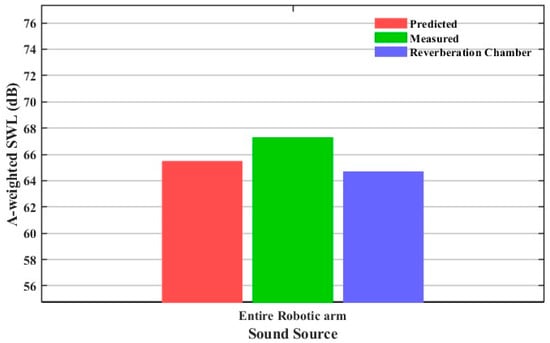
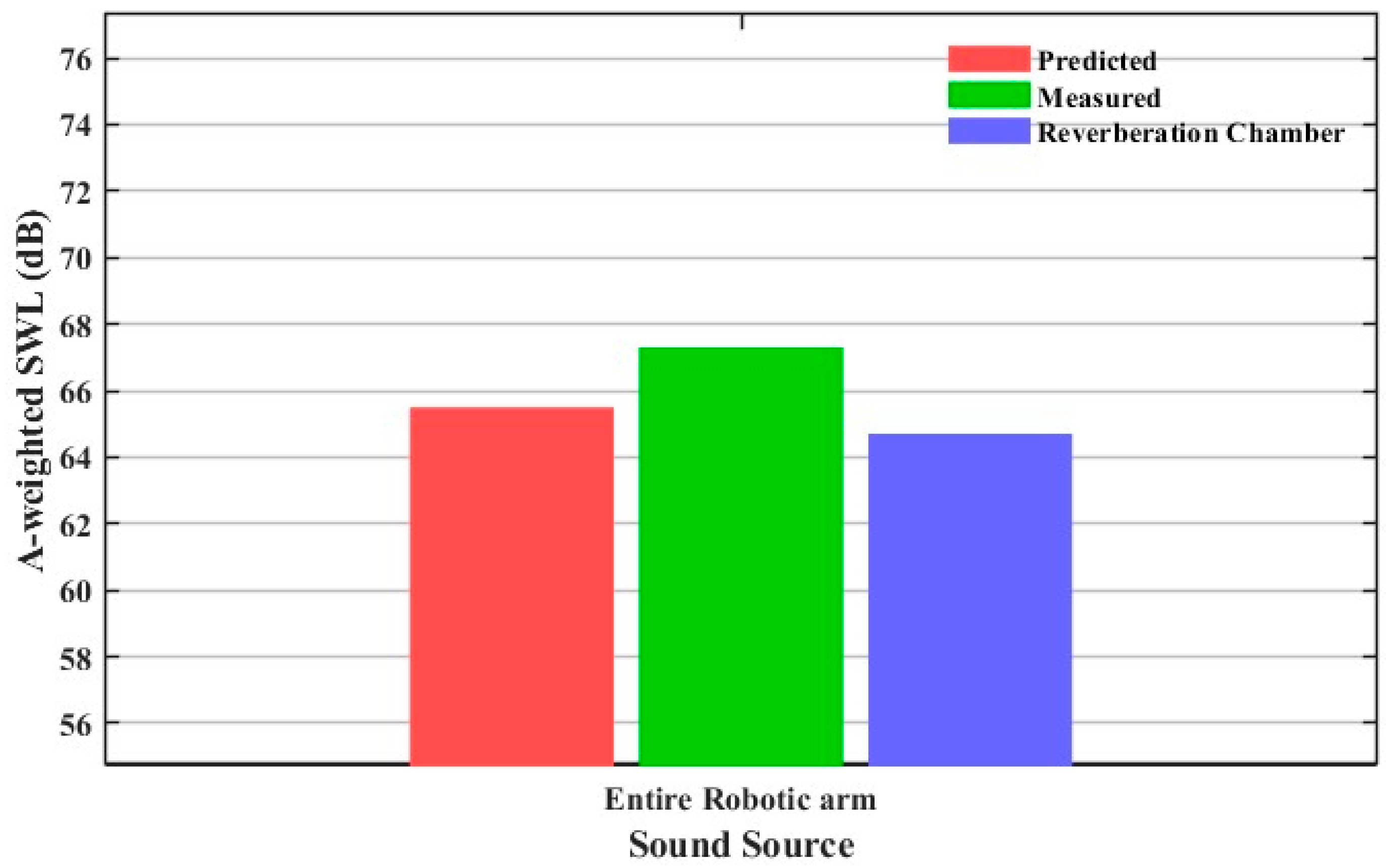
Based on the single-joint SWLs and distance corrections detailed in Section 3.1, the predicted overall machine noise was calculated using Equations (8) and (9). To validate this prediction, actual overall noise levels were measured in a reverberation chamber (as a reference) and directly in a semi-anechoic chamber via the 4-point method. A comprehensive comparison of these three scenarios is presented in Figure 6.
Figure 6.
The SWLs of entire robotic arm measured and predicted in the semi-anechoic chamber alongside the SWLs measured in the reverberation chamber.
Results demonstrate that the single-joint prediction method yields a SWL deviation of only 0.8 dB relative to reverberation chamber references, significantly outperforming direct measurements (2.6 dB). This confirms that the proposed approach effectively mitigates measurement inaccuracies induced by complex spatial trajectories, providing superior precision compared to direct measurement in semi-anechoic environments.
4. Discussion
4.1. Verification of Measurement 9-Point Method
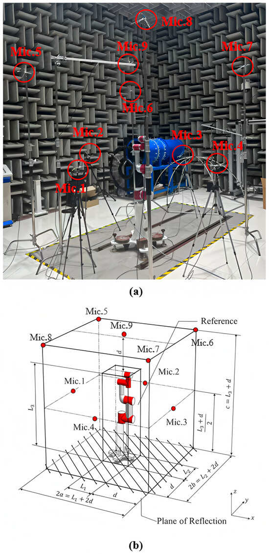
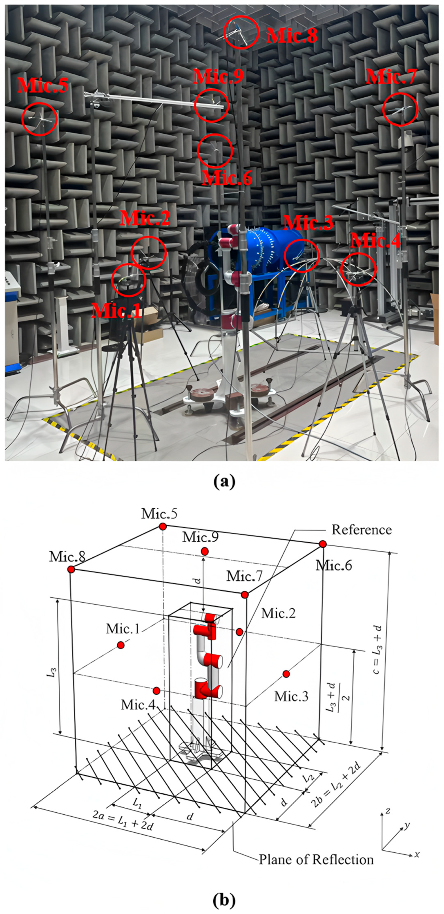
To account for source directionality and its impact on measurement accuracy, the single-joint noise was reevaluated using a 9-point array as prescribed by ISO 3744:2025 [7]. This configuration augments the original 4-point array with five additional microphones at a height of 2.5 m: One positioned on the vertical axis of the robot base and four along the diagonals of the square array (see Figure 7a,b).
Figure 7.
Layout of Nine Measuring Points. (a) Layout of the semi-anechoic chamber; (b) Schematic of the measurement points.
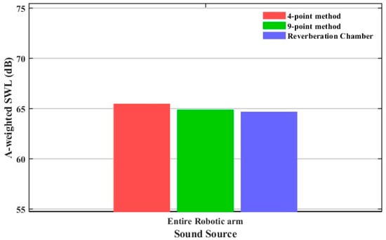
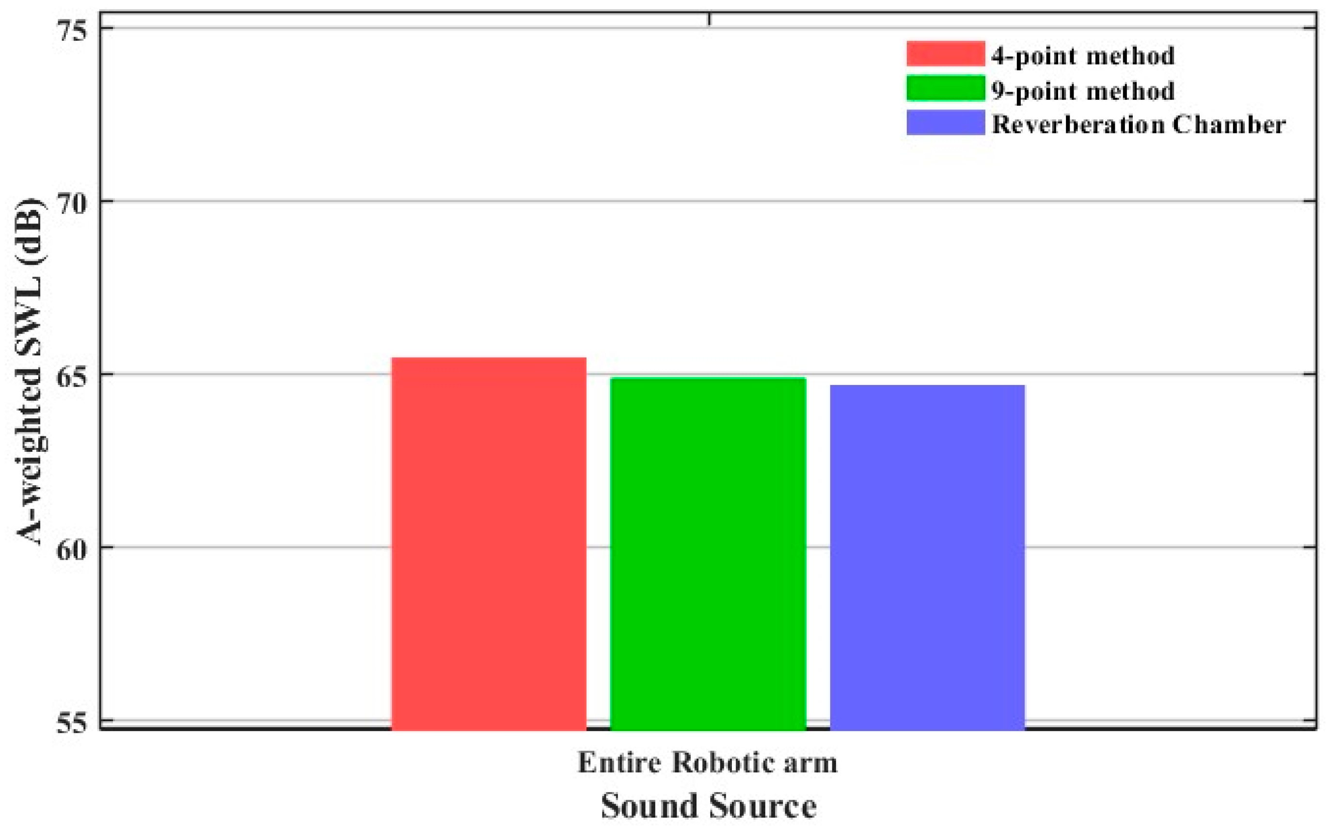
Following the 10-s data collection and calculation procedures detailed in Section 3, the resulting SWLs were compared against 4-point and reverberation chamber benchmarks (Figure 8). The 9-point method yielded a deviation of only 0.2 dB relative to the reverberation chamber, significantly lower than the 0.8 dB error produced by the 4-point method. This confirms that increased spatial sampling density effectively mitigates biases caused by source directionality.
Figure 8.
The SWLs of entire robotic arm using 4-point method and 9-point method in the semi-anechoic chamber alongside the SWLs measured in the reverberation chamber.
However, the 9-point configuration entails a larger operational footprint, higher sensor costs, and stricter environmental requirements. In space-constrained industrial settings, such as crowded workshops, implementing a 9-point array for six-joint robots poses significant logistical challenges. While the 9-point method provides a more faithful acoustic representation, the 4-point method’s accuracy remains sufficient for standard engineering requirements. Consequently, considering the trade-off between precision and operational feasibility, the 4-point method is identified as the more practical solution for this application.
4.2. The Compact Reference Body
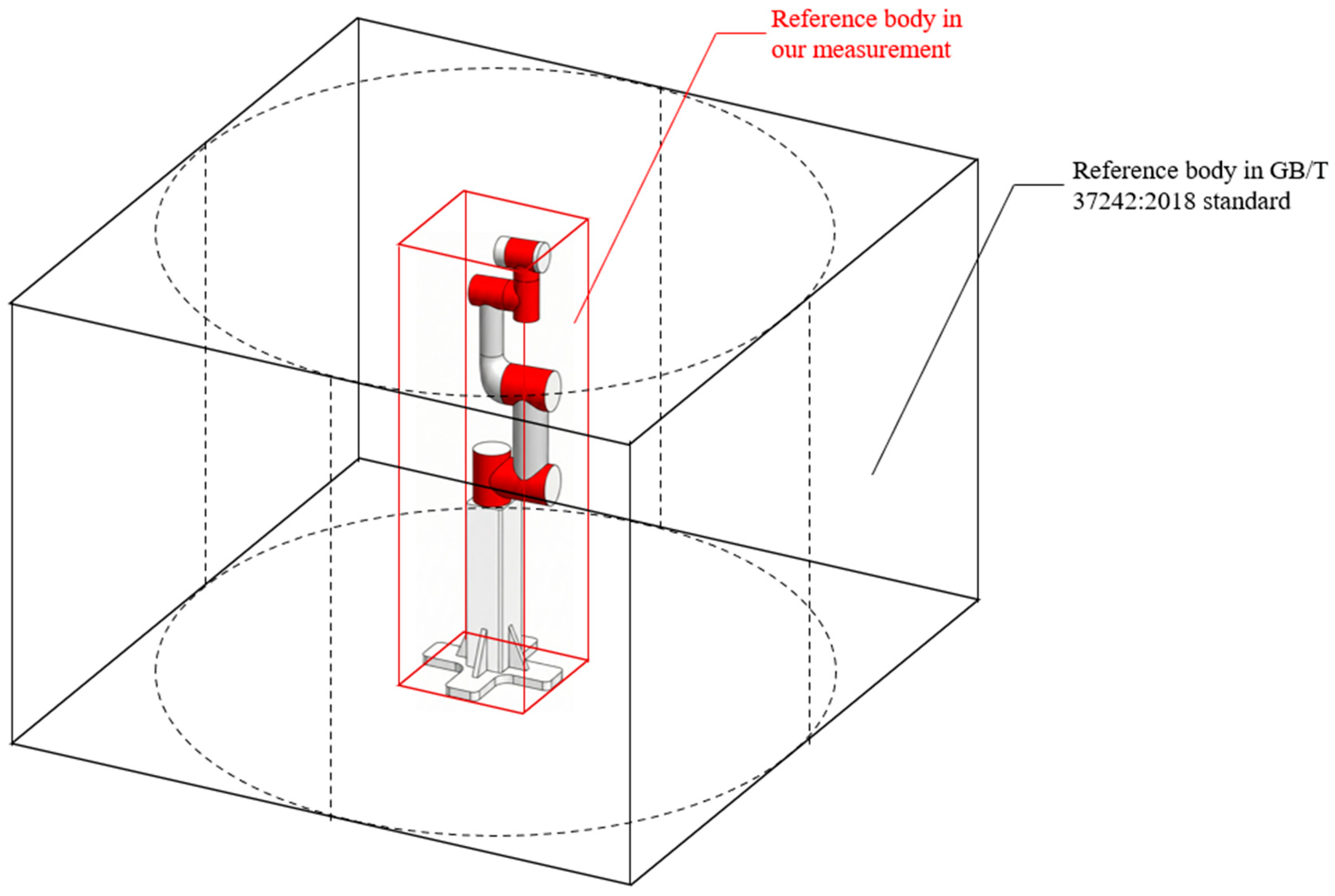
Defining the reference body is a prerequisite for establishing measurement positions (see Section 2.2). Per the GB/T 37242:2018 standard [15], the reference body is typically derived from the robot’s maximum operating envelope (black parallelepiped, Figure 9), encompassing its full horizontal and vertical reach.
Figure 9.
Comparison between the standard-compliant reference body (GB/T 37242:2018 [15]) and the compact reference body in this study.
However, as this study employs single-joint measurements in fixed postures, the sound source remains stationary, making the full-envelope definition redundant. Consequently, a compact reference body tailored to the specific testing pose was adopted (red parallelepiped, Figure 9). This optimization significantly reduces the measurement surface area and site requirements while maintaining measurement validity, making it more suitable for localized acoustic characterization.
4.3. Validation of Measurement Point Configuration
While the height and baseline layout of the measurement points in this study are strictly governed by established acoustic standards (such as GB/T 37242:2018 [15]), a supplementary spatial acoustic mapping was conducted to validate the spatial robustness and determine the optimal number of these points. Using Joint 1 as the test subject, a high-resolution directional distribution was captured by deploying 24 measurement points. These points were arranged circumferentially at 15° intervals, maintaining a standard height of 1.5 m and a 1 m distance from the reference surface.
To evaluate the influence of different point topologies, specific sub-configurations were extracted from this dataset. The analysis revealed that selecting six entirely distinct combinations of 4 measurement points (each spaced at 90° intervals) resulted in a maximum deviation in the average SPL of less than 0.3 dB. Conversely, reducing the spatial resolution to a 3-point configuration (spaced at 120° intervals) noticeably increased the maximum error to 0.74 dB. These empirical findings demonstrate that a 3-point topology is insufficient to capture the acoustic characteristics accurately, whereas the standardized 4-point scheme is highly robust against spatial rotations. Therefore, the 4-point method adopted in this paper effectively balances engineering efficiency with measurement stability.
4.4. Limitations
Despite the significant improvement in measurement accuracy achieved by the proposed method, several limitations remain to be addressed in future research.
First, this study serves as a preliminary validation of a practical measurement framework; as such, it lacks a comprehensive statistical characterization. Future work will include rigorous repeatability and reproducibility tests and the establishment of statistical confidence intervals to ensure the robustness of the results across different testing environments. Furthermore, a formal uncertainty quantification is required to account for variables such as background noise fluctuations, sensor positioning errors, and environmental reflections.
Second, although the proposed method achieves relatively accurate measurement of the robotic arm’s noise in practical applications, it still possesses deficiencies in theoretical derivation and precise modeling. The current correction approach relies significantly on empirical adjustments, which may not fully capture the complex acoustic-structural coupling of multi-joint systems. In subsequent research, we will conduct further studies to refine the underlying mathematical frameworks and develop more sophisticated models to improve the method’s generalizability.
Lastly, persistent discrepancies were observed in joints with lower emission levels. This suggests that the current framework may not fully capture the complex signal-to-noise dynamics or the specific frequency-domain characteristics of quieter components. Refinement of the method to include frequency-dependent weighting or more nuanced near-field to far-field transitions remains a priority for the next iteration of this research.
5. Conclusions
To address measurement inaccuracies caused by moving sound sources and acoustic obstruction in multi-joint robots, this study proposed a predictive method based on single-joint measurements with distance correction. Validation against reverberation chamber benchmarks demonstrated that the proposed method significantly improved accuracy, yielding a deviation of only 0.8 dB, compared to 2.6 dB for direct measurement. Furthermore, while a 9-point measurement configuration was found to better mitigate source directionality, the 4-point method was determined to be the optimal choice for industrial applications when balancing accuracy with operational feasibility.
A primary advantage of this method lies in its experimental simplification. It eliminates the need for complex, resource-intensive measurements under multi-joint coupled motions. Instead, it predicts the multi-joint acoustic response by combining controlled single-joint sound pressure data with the robot’s full-system operating program, thereby reducing systematic biases induced by motion and occlusion. Furthermore, the method significantly improves operational efficiency by streamlining the data acquisition process. Evaluations of different measurement-point layouts further highlight its strong applicability in industrial contexts. By accommodating practical constraints such as test time, available space, and operator complexity, the proposed approach demonstrates high operational efficiency, robust industrial applicability, and scalable deployment.
Author Contributions
Conceptualization and methodology, Y.H.; Experiment, W.Z.; Data analysis, W.Z.; Writing—original draft preparation, W.Z.; Writing—review, Y.H. All authors have read and agreed to the published version of the manuscript.
Funding
This research was funded by Guangxi Science and Technology Major Project (AA24206071) and National Natural Science Foundation of China (52072242).
Institutional Review Board Statement
Not applicable.
Informed Consent Statement
Not applicable.
Data Availability Statement
The data that support the findings of this study are available from the corresponding author upon request.
Conflicts of Interest
The authors declare no conflicts of interest.
References
- Kim, Y.-S.; Dagalakis, N.G.; Marvel, J.; Cheok, G. Design and Testing of Wireless Motion Gauges for Two Collaborative Robot Arms. Meas. Sci. Rev. 2022, 22, 84–91. [Google Scholar] [CrossRef] [Scilit]
- Knežević, N.; Bjelić, M.; Jovanović, K. Automated Sound Intensity Measurement With Robot And Intensity Probe. Int. J. Electr. Eng. Comput. 2018, 2, 1. [Google Scholar]
- Ahn, S.; Kim, J.-H.; Heo, J.; Ahn, S.-H. Human-Robot and Robot-Robot Sound Interaction Using a 3-Dimensional Acoustic Ranging (3DAR) in Audible and Inaudible Frequency. Robot. Comput.-Integr. Manuf. 2025, 94, 102970. [Google Scholar] [CrossRef] [Scilit]
- Sievers, T.S.; Ewers, J.; Heine, J.; Kuschel, N.; Marhenke, L.; Sindlinger, M.; Wassermann, N.; Tracht, K. Soundscape Generation for Virtual Human Robot Collaboration. Procedia CIRP 2022, 107, 1005–1010. [Google Scholar] [CrossRef] [Scilit]
- Cernohlavek, V.; Klimenda, F.; Houska, P.; Suszyński, M. Vibration Measurements on a Six-Axis Collaborative Robotic Arm—Part I. Sensors 2023, 23, 1629. [Google Scholar] [CrossRef] [Scilit] [PubMed]
- Wessels, M.; de Heuvel, J.; Müller, L.; Maier, A.L.; Bennewitz, M.; Kraus, J. Auditory Localization and Assessment of Consequential Robot Sounds: A Multi-Method Study in Virtual Reality. arXiv 2025, arXiv:2504.00697. [Google Scholar] [CrossRef] [Scilit]
- ISO 3744:2025; Acoustics—Determination of Sound Power Levels of Noise Sources Using Sound Pressure—Engineering Methods for an Essentially Free Field over a Reflecting Plane. ISO: Geneva, Switzerland, 2025.
- ISO 3747:2010; Acoustics—Determination of Sound Power Levels and Sound Energy Levels of Noise Sources Using Sound Pressure—Engineering/Survey Methods for Use In Situ in a Reverberant Environment. ISO: Geneva, Switzerland, 2010.
- ISO 9614-1:1993; Acoustics—Determination of Sound Power Levels of Noise Sources Using Sound Intensity—Part 1: Measurement at Discrete Points. ISO: Geneva, Switzerland, 1993.
- ISO 2151:2004; Acoustics—Noise Test Code for Compressors and Vacuum Pumps—Engineering Method (Grade 2). ISO: Geneva, Switzerland, 2004.
- ISO 6393:2008; Earth-Moving Machinery—Determination of Sound Power Level—Stationary Test Conditions. ISO: Geneva, Switzerland, 2008.
- ISO 5136:2003; Acoustics—Determination of Sound Power Radiated into a Duct by Fans and Other Air-Moving Devices—In-Duct Method. ISO: Geneva, Switzerland, 2003.
- IEC 60704-1:2021; Household and Similar Electrical Appliances—Test Code for the Determination of Airborne Acoustical Noise—Part 1: General Requirements. IEC: Geneva, Switzerland, 2021.
- ECMA-74; Measurement of Airborne Noise Emitted by Information Technology and Telecommunications Equipment. ECMA International: Geneva, Switzerland, 2025.
- GB/T 37242; 2018 Test Method for Robot Noise. Standards Press of China: Beijing, China, 2018. (In Chinese)
- ISO 354:2003; Acoustics—Measurement of Sound Absorption in a Reverberation Room. International Organization for Standardization: Geneva, Switzerland, 2003.
- IEC 61400-11:2012; Wind Turbines—Part 11: Acoustic Noise Measurement Techniques. IEC: Geneva, Switzerland, 2012.
- Alkmim, M.; Cardenuto, J.; Tengan, E.; Dietzen, T.; Van Waterschoot, T.; Cuenca, J.; De Ryck, L.; Desmet, W. Drone Noise Directivity and Psychoacoustic Evaluation Using a Hemispherical Microphone Array. J. Acoust. Soc. Am. 2022, 152, 2735–2745. [Google Scholar] [CrossRef] [Scilit] [PubMed]
- ISO 362-1:2022; Acoustics—Engineering Method for Noise Emitted by Accelerating Road Vehicles—Part 1: M and N Categories. ISO: Geneva, Switzerland, 2022.
- Treichel, J.; Foerster, J.; Volkert, A.; Lieb, T.J. Applicability of ISO Standard 3744 to UA. In Proceedings of the EUROREGIO/BNAM 2022, Aalborg, Denmark, 9–11 May 2022; pp. 45–46. Available online: https://bnam2022.org (accessed on 1 June 2022).
- Cai, Y.; Liu, X.; Xiong, Y.; Wu, X. Three-Dimensional Sound Field Reconstruction and Sound Power Estimation by Stereo Vision and Beamforming Technology. Appl. Sci. 2021, 11, 92. [Google Scholar] [CrossRef] [Scilit]
- Xiong, Y.; Liu, X.; Wu, X. The estimation of distance and power of multiple sound sources by combining three-dimensional sound intensity and beamforming. Appl. Acoust. 2022, 199, 109020. [Google Scholar] [CrossRef] [Scilit]
- Gao, K.; Kuai, H.; Huang, S.; Jiang, W. Localization of broadband acoustical sources in the cylindrical duct via measurements outside the duct end. J. Sound Vib. 2023, 562, 117749. [Google Scholar] [CrossRef] [Scilit]
- Okoyenta, A.R.; Wu, H.; Liu, X.; Jiang, W. A Short Survey on Green’s Function for Acoustic Problems. J. Theor. Comput. Acous. 2020, 28, 1950025. [Google Scholar] [CrossRef] [Scilit]
- Bugaru, M.; Vasile, O.; Neagoe, M. Recent Developments of Noise Attenuation Using Acoustic Barriers for a Specific Edge Geometry. Computation 2021, 9, 129. [Google Scholar] [CrossRef] [Scilit]
- Steffensen, J.F. Interpolation, 2nd ed.; Dover Publications: Mineola, NY, USA, 2006. [Google Scholar]
- Zhang, P.; Yang, C.; Huang, Y. An improved algorithm for liner impedance eduction in low signal-to-noise ratio flow duct. Int. J. Aeroacoust. 2022, 21, 168–189. [Google Scholar] [CrossRef] [Scilit]
- Zhang, X.-Z.; Bi, C.-X.; Zhang, Y.-B.; Xu, L. Transient nearfield acoustic holography based on an interpolated time-domain equivalent source method. J. Acoust. Soc. Am. 2011, 130, 1430–1440. [Google Scholar] [CrossRef] [Scilit] [PubMed]
- Wu, H.; Zhang, Y.; Jiang, W. An interpolation method for the measured velocity and itsapplication in the prediction of acoustic radiation of submerged cylindrical shell structures. Acta Acust. 2015, 40, 631–638. [Google Scholar] [CrossRef]
- ISO 3741:2010; Acoustics—Determination of Sound Power Levels and Sound Energy Levels of Noise Sources Using Sound Pressure—Precision Methods for Reverberation Test Rooms. ISO: Geneva, Switzerland, 2010.

Disclaimer/Publisher’s Note: The statements, opinions and data contained in all publications are solely those of the individual author(s) and contributor(s) and not of MDPI and/or the editor(s). MDPI and/or the editor(s) disclaim responsibility for any injury to people or property resulting from any ideas, methods, instructions or products referred to in the content. |
© 2026 by the authors. Licensee MDPI, Basel, Switzerland. This article is an open access article distributed under the terms and conditions of the Creative Commons Attribution (CC BY) license.