


Abstract
Aiming at cemented tailings backfill (CTB) damage and collapse induced by secondary stope blasting in the sublevel open stoping with a subsequent filling method, a new CTB damage control technology termed “Synergistic Utilization of Cumulative Blasting Damage (SU-CBD)” is proposed. First, theoretical analysis is conducted to reveal the influence mechanism of rock mass damage accumulation on its blastability, verifying the feasibility of the SU-CBD technology. Subsequently, based on the LS-DYNA R11.1 software and RHT material model, a numerical model is established, and the small restart technique is adopted to realize the continuous simulation of multi-row blasting. By comparing the rock mass fragmentation ratio, energy distribution, and CTB damage degree among different charge structure schemes, the optimal charge structure combination is obtained. To address the issues of retained rock mass damage and overbreak caused by multiple blasting operations, a dynamic adjustment method for blasthole row spacing is proposed, with the optimal row spacing increment determined as 1.0 m. To verify the technical effectiveness, field industrial tests are carried out in Stope No. 5 of the 4500 m–4550 m mining level in the Bangzhong Zinc-Copper Mine. The results show that the optimized blasting scheme keeps the CTB intact without collapse and achieves uniform ore fragmentation, and the oversize ore ratio (particle size > 50 cm) is only 2.4%, with the numerical simulation results in good agreement with the field test results. The research indicates that the SU-CBD technology can effectively reduce the powder factor and CTB blasting damage while ensuring the blasting fragmentation effect, providing reliable blasting design support for the secondary stope.
1. Introduction
The sublevel open stoping with a subsequent filling method has gradually become the mainstream mining method for thick ore bodies in China due to its advantages of high production capacity, low mining cost, and excellent safety performance [1,2]. This mining method generally adopts a two-step stoping mode: first, the primary stope is mined, and then, the goaf is filled with cemented tailings backfill (CTB) [3,4]. As a vertical artificial pillar, the CTB is conducive to improving the ground pressure environment and provides safety protection for the subsequent mining of the secondary stope [5]. During the mining process of the secondary stope, blasting exerts intense impact and damage effects on the CTB, which may easily lead to spalling and collapse of the CTB, resulting in ore dilution and even overall collapse of the CTB. Numerous researchers have confirmed that blasting disturbance is the primary cause of the damage and instability of backfill [4,6,7]. Therefore, studying the CTB damage control technology under dynamic blasting loads to ensure the stability of CTB is the key to the successful application of the sublevel open stoping with a subsequent filling method [8,9].
Numerous scholars have conducted extensive research on the damage and instability mechanisms of backfill under dynamic blasting loads. Tan et al. [10] systematically analyzed the dynamic stress−strain relationship, strength characteristics, and failure modes of backfill specimens by varying the cement−sand ratio and solid particle content. Liu et al. [11] revealed the crack propagation mechanism and failure process of jointed specimens under dynamic impact by means of high-speed photography and scanning electron microscopy. Cao et al. [12] studied the relationship between the dynamic compressive strength of backfill and strain rate, and concluded that the dynamic compressive strength is positively correlated with the strain rate. Owing to the difference in wave impedance between CTB and ore, complex transmission and reflection phenomena occur when blasting stress waves propagate to the medium interface. Liu et al. [13] argued that during the secondary stoping process, stress waves mainly undergo reflection at the ore−CTB interface, and the transmitted stress in the CTB is highly sensitive to the distance from the charge cartridge. Fan et al. [14] and Li et al. [15] investigated the influence of joints on the wave propagation process and concluded that the intensity of transmitted waves is positively correlated with that of incident waves. The above studies indicate that although the propagation law of stress waves at heterogeneous interfaces is relatively complex, controlling the intensity of incident stress waves is an effective method to reduce the intensity of stress waves transmitted into CTB. Therefore, a great deal of blasting excavation practice adopts methods such as presplit blasting, slotted cartridges, and shaped charge cartridges to block the propagation of stress waves for the control of blasting damage [16,17,18,19,20]. However, the aforementioned methods suffer from drawbacks such as the need for additional construction of presplit blastholes, customized charge cartridges, and complex charging procedures, which will increase construction costs and result in poor applicability for stope blasting operations. Therefore, mines often adopt measures such as optimizing the blasting sequence and improving the strength of backfill to ensure the stability of CTB. Zhao et al. [21] adopted a three-dimensional blasting model test combined with dynamic response monitoring technology to study the influence of blasting delay time on the dynamic response characteristics of backfill, and found that delayed initiation induces the least damage to backfill. Huang et al. [22] analyzed the propagation law of blasting stress waves in full tailings cemented backfill and their interaction effects with the medium interface, and proposed the failure modes and corresponding particle vibration velocity thresholds of backfill with different cement−sand ratios. Emad et al. [23] simulated the blasting process based on the FLAC3D software, calibrated the model with field blasting vibration monitoring data, further analyzed the failure mechanism of backfill and evaluated its stability under dynamic loads. Li et al. [7] analyzed the influence of blasting schemes and cement−sand ratios on adjacent backfill through numerical simulation, and found that the disturbance to backfill is relatively small under simultaneous initiation conditions. Suazo et al. [24] used the LS-DYNA software to focus on the influence of factors such as the initiation sequence and the number of blasting events on the pore pressure in backfill. Wu [25] explored the influence of backfill protective layer thickness and minimum burden on the blasting damage of backfill by using the LS-DYNA software, and obtained the optimal combination of blasting parameters. Zhao Yong [26] proposed the “CLB” backfill blasting damage control technology and verified its effectiveness in field applications.
However, the aforementioned CTB damage control technologies fail to fully utilize the cumulative effect of blasting damage. In the actual stoping process of the stope, blasting operations are often carried out repeatedly, and millisecond delay blasting technology is mostly adopted in each cycle [27]. The cumulative damage caused by multiple blasting events can significantly enhance rock mass blastability [28,29,30], on the basis of which the explosive charge can be systematically reduced, and the stress waves transmitted to the adjacent cemented tailings backfill (CTB) can be simultaneously diminished, thereby mitigating the blasting damage to the backfill. This paper proposes a new technique termed “Synergistic Utilization of Cumulative Blasting Damage (SU-CBD)” for CTB damage control. This technology holds that the cumulative damage of rock mass induced by multiple blasting events can significantly enhance rock mass blastability, on the basis of which the explosive charge can be systematically reduced in subsequent blasting operations. Meanwhile, such cumulative damage can attenuate the peak value of stress waves transmitted to the backfill by blasting, thus effectively mitigating the blasting damage to cemented tailings backfill (CTB) on the premise of ensuring the ore fragmentation effect. For the first time, this technology incorporates the cumulative damage effect of multi-row blasting into the optimization system of charge structure and blasthole pattern parameters, breaking through the mindset of existing technologies that only reduce the charge of boundary blastholes. By actively utilizing the cumulative damage effect, it realizes the synergistic reduction of explosive charge in multiple blastholes on the premise of guaranteeing the ore fragmentation effect, thereby improving the control effect of CTB blasting damage. To verify the feasibility of the SU-CBD technology, the paper carried out the following work: (1) based on the blasting wave propagation theory and damage mechanics, the influence of cumulative blasting damage on rock mass blastability (characterized by the fractured zone radius) and the peak radial stress at the ore−CTB interface was analyzed from a theoretical perspective; (2) based on the LS-DYNA R11.1 numerical simulation software and the small restart technique, a numerical modeling framework suitable for simulating the cumulative damage of multi-row blasting was constructed. In accordance with the evolution law of rock mass cumulative damage, the charge structure and blasthole pattern parameters of multi-row blastholes were optimized in a synergistic manner, and the optimal blasting scheme was determined; (3) taking the Bangzhong Zinc-Copper Mine as the engineering background, the application effect of the SU-CBD technology in CTB blasting damage control and ore fragmentation was verified through field industrial tests.
2. Engineering Background
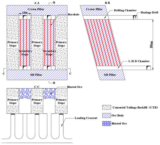
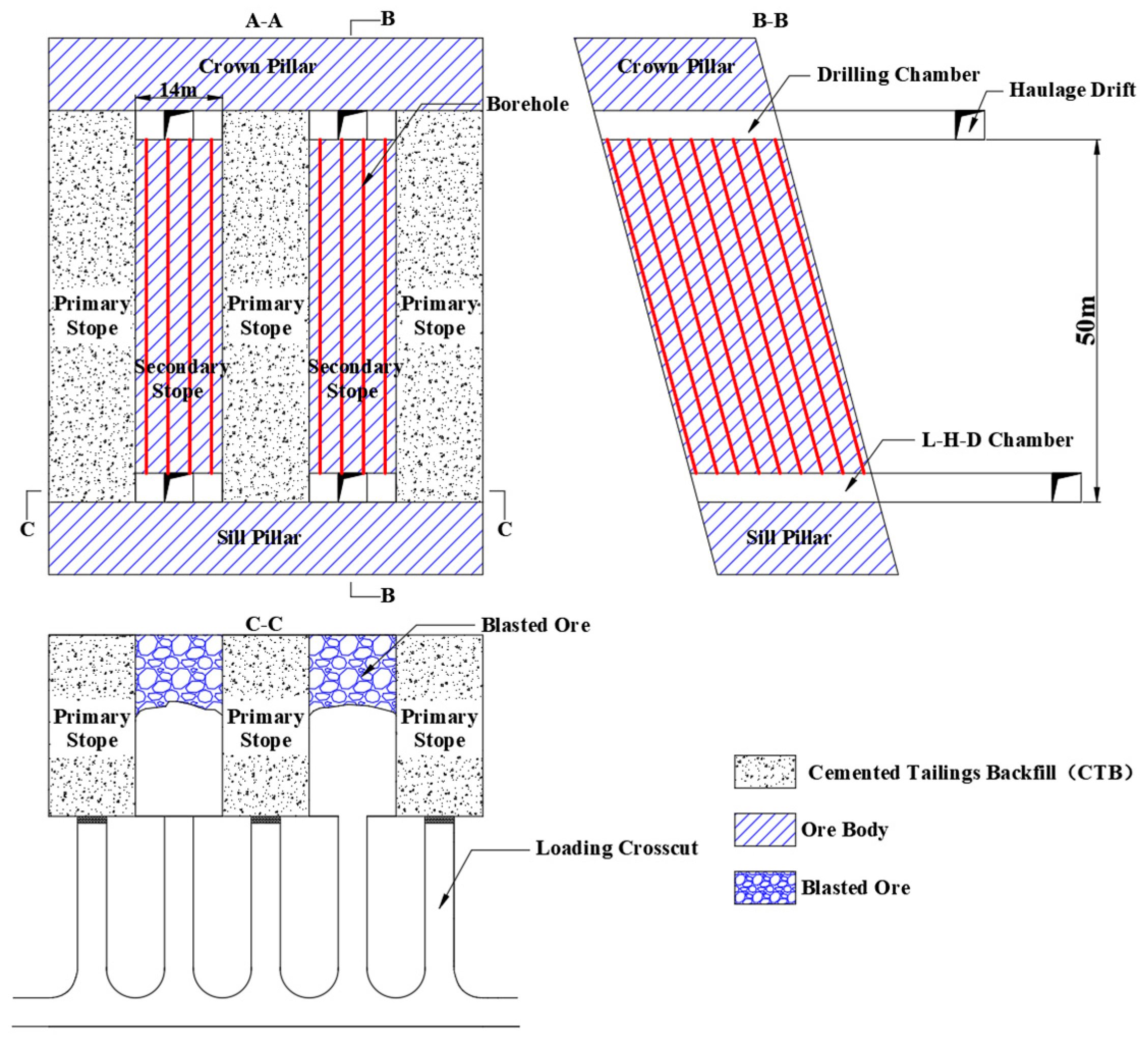
The Bangzhong Zinc-Copper Mine, operated by Tibet Zhongkai Mining Co., Ltd., is located in Linzhou County, Tibet Autonomous Region, China. The deposit is a zinc−copper symbiotic ore body with an average thickness of 25 m and a dip angle of 77°, classifying it as a steeply dipping and thick ore body. The mine employs a sublevel open stoping method with subsequent backfill (Figure 1), with a standard level height of 50 m. The stope dimensions are 25 m in length, 14 m in width, and 50 m in height (L × W × H).
Figure 1.
Schematic diagram of the stage open stope with a subsequent backfill mining method.
The adoption of large-diameter longhole blasting has significantly increased the mine’s production capacity and efficiency. However, this advancement concurrently imposes more stringent requirements on blast design parameters. During the secondary stoping sequence, the Cemented Tailings Backfill (CTB) adjacent to the blasting zones is subjected to intense dynamic impact. This frequently leads to severe CTB damage and collapse, resulting in substantial ore dilution while compromising both drawing efficiency and operational safety. Consequently, developing effective CTB damage control techniques to ensure CTB stability during secondary stoping is critically important for the mine.
Given the mine’s relatively shallow depth, the in situ stress within the study area is low, with the maximum principal stress estimated at approximately 8 MPa. Furthermore, due to the stress-shadowing effect provided by the cut slot in the stope, the in situ stress in the immediate blasting region is even lower [27]. Therefore, the influence of in situ stress on blasting outcomes can be considered negligible. The physical and mechanical parameters of the host rock and the CTB, obtained through laboratory tests, are listed in Table 1 and Table 2, respectively.
Table 1.
Physical and mechanical parameters of ore.
Table 2.
Physical and mechanical parameters of CTB.
3. Theoretical Analysis on the Feasibility of the SU-CBD Technology
3.1. Cumulative Blasting Damage Definition
Cumulative blasting damage refers to a nonlinear cumulative process in which internal microscopic defects (microcracks) of rock mass continuously initiate, propagate and connect under the repeated action of multiple blasting loads, leading to the irreversible and continuous deterioration of macroscopic mechanical properties (strength and integrity), and may eventually trigger overall instability. It is not the failure result of a single blasting event, but a process in which damage accumulates continuously with the increase in the number of blasting operations in frequent blasting activities such as tunnel excavation and mine mining. The damage variable D is generally used to describe the degree of blasting damage sustained by rock mass. A value of D = 0 indicates that the rock mass is undamaged, while D = 1 means the rock mass is completely damaged. Typically, the damage variable D can be expressed as: , where s is the strength of the rock mass after blasting and is the undamaged strength of the rock mass before blasting.
3.2. Blasting Load in Rock and Its Propagation Law
After the explosive in the blasthole is detonated, it acts on the hole wall in the form of a detonation wave. According to the C-J theory of condensed explosives, the gas pressure on the detonation wave front after explosive detonation is [31]:
where is the detonation pressure (Pa), VOD is the velocity of detonation (m/s), is the density of unreacted explosive (kg/m3), and γ is the ratio of the specific heats for the detonation gases. In this study, an emulsion explosive with a VOD of 4000 m/s and a density of 1180 kg/m3 was selected to calculate the blasthole wall pressure.
When the detonation product begins to expand, its initial average pressure is approximately half of the detonation pressure for coupled charges.
For decoupled charges, the initial average pressure involved is as follows:
where λ is the average adiabatic expansion constant of the explosive, is the diameters of the charge, is the diameters of the blasthole, and and are the length of the charge and the blasthole, respectively. For explosives, γ and λ can be approximately taken as 3.0 and 1.5, respectively [32].
According to relevant studies, when the detonation product collides with the blasthole wall, the pressure increases significantly. The peak pressure exerted on the blasthole wall has the following expression:
where is the borehole wall pressure (Pa), and is the pressure increase coefficient and can be approximately taken as 10 [33].
The attenuation law of the peak radial and circumferential stress amplitudes of stress waves induced by single-hole explosion in rock with distance can be expressed as follows:
where refers to the peak radial stress wave amplitude (MPa); refers to the peak circumferential stress wave amplitude (MPa); is the stress lateral pressure coefficient in rock, given by , and the negative sign indicates tensile stress; is the distance from a given point to the central axis of the blasthole (m); is the pressure attenuation coefficient. In the shock wave action zone, ; in the stress wave action zone, , where denotes the dynamic Poisson’s ratio of rock.
The dynamic Poisson’s ratio of rock is approximately related to the static Poisson’s ratio as follows:
where and represent the dynamic and static Poisson’s ratios of rock, respectively.
3.3. Charge Structure Optimization Method Based on the SU-CBD Technology
Based on the blasting theory, when the stress in rock exceeds its failure strength, macroscopic failure will occur, generating a crushed zone and a fractured zone. When these two zones form around a single blasthole, the stress in rock shall satisfy the following conditions:
where is the dynamic compressive strength of the rock (MPa); is the dynamic tensile strength of the rock (MPa); is the rock damage variable, which is used to characterize the damage degree of the rock mass.
Therefore, the calculation formulas for the radius of the crushed zone and fractured zone during single-hole blasting can be derived as follows:
where is the radius of the crushed zone (m); is the radius of the fractured zone (m).
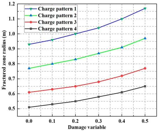
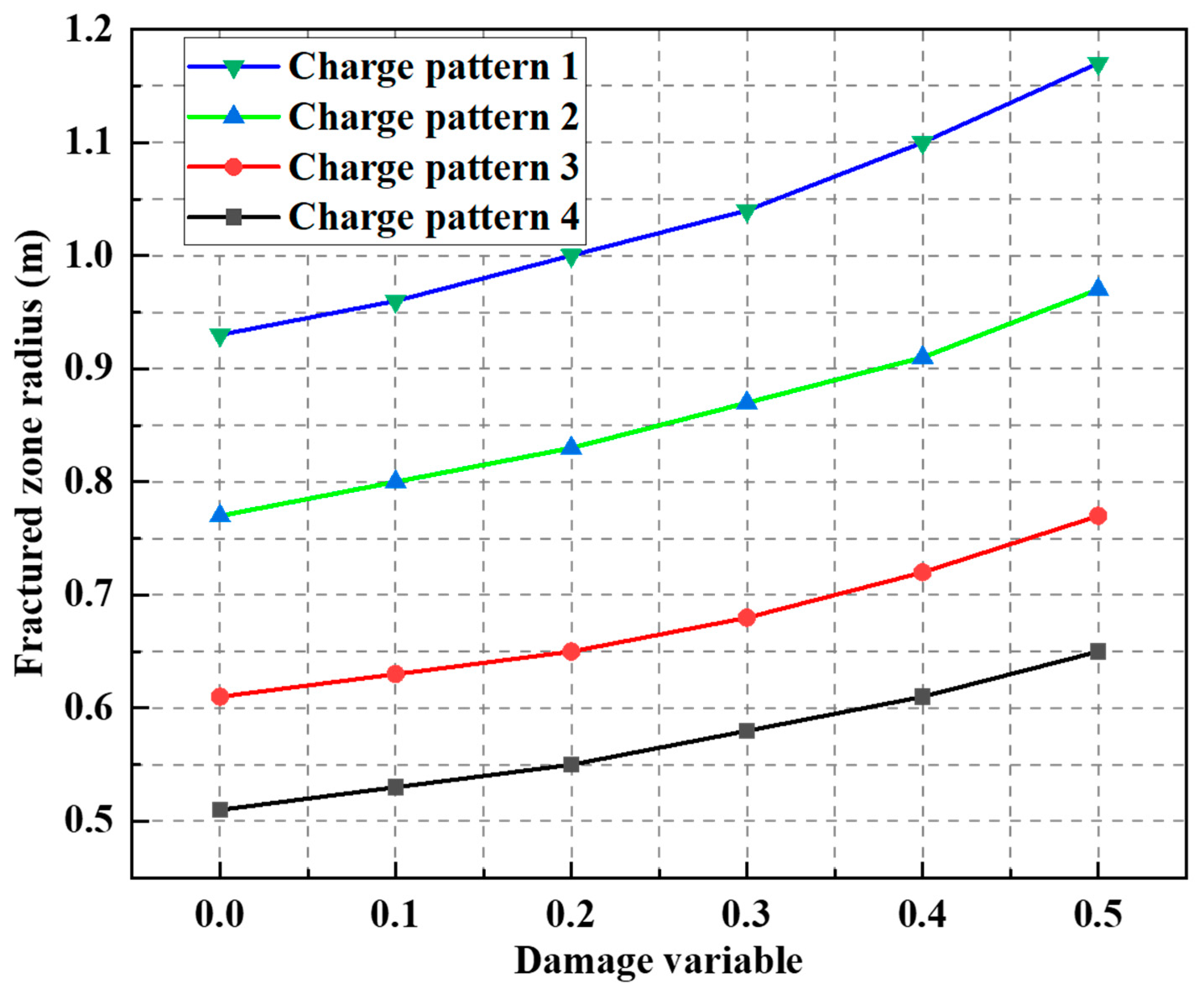
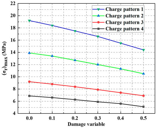
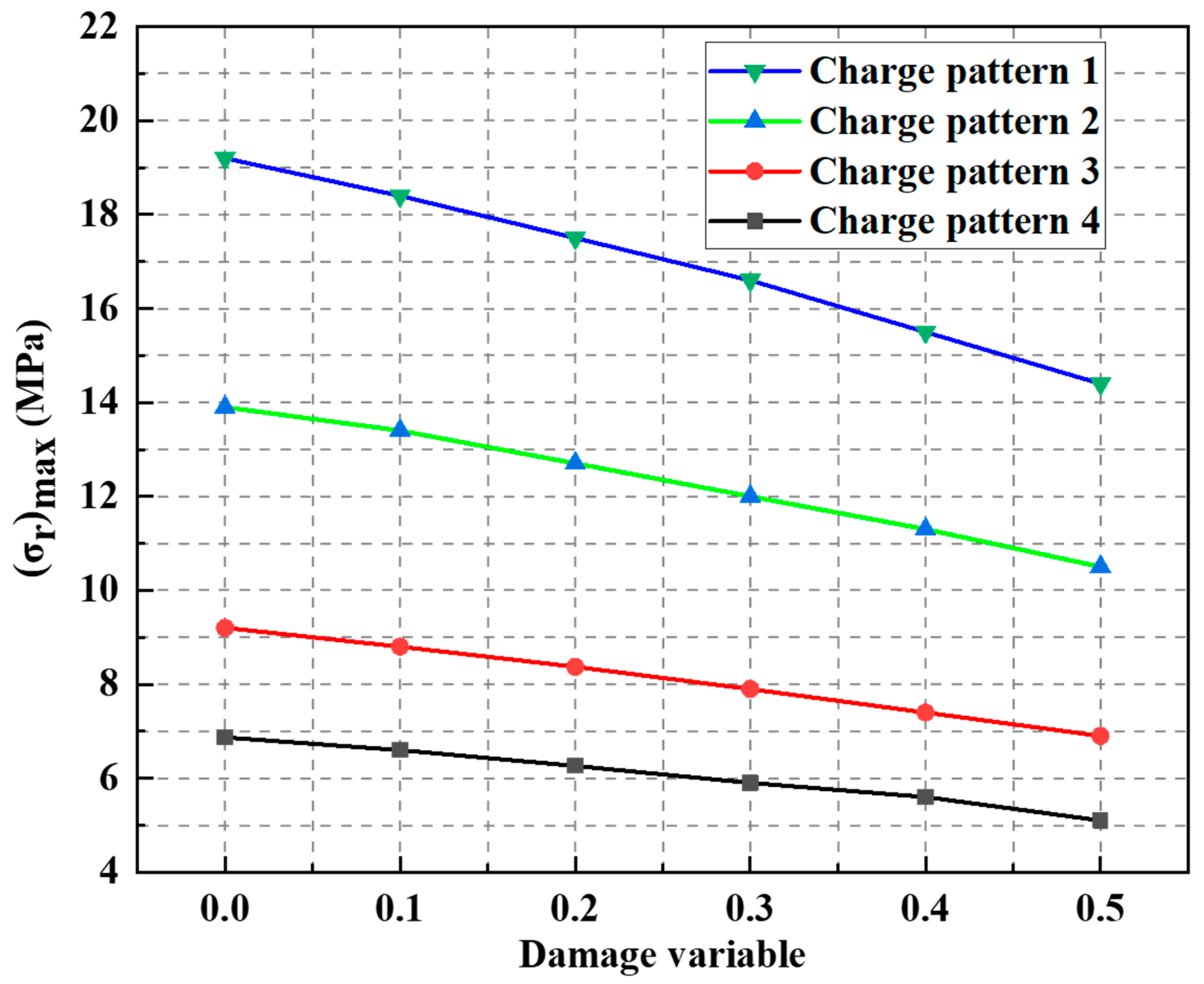
With reference to the field conditions, four charge structures were designed. Specifically, charge patterns 1 to 4 were configured as follows: a 1.5 m charge with a 1.0 m air deck, a 1.0 m charge with a 1.0 m air deck, a 1.0 m charge with a 1.5 m air deck, and a 0.5 m charge with a 1.0 m air deck. The borehole diameter was 165 mm and the explosive diameter was 140 mm. Through calculation, the relationship between the fractured zone radius and rock mass damage variable for the above four charge structures is illustrated in Figure 2. As can be seen from Figure 2, the fractured zone radius increases gradually with the rise in the rock mass damage variable, indicating an improved rock blastability. This is conducive to reducing the powder factor and minimizing the blasting disturbance to the CTB. The distance between the boundary hole and the CTB, as designed in the mine, was 1.0 m. The calculated relationship between the peak radial stress on the ore side of the CTB−ore interface and the rock mass damage variable for the four charge structures is shown in Figure 3. It can be observed from Figure 3 that the peak radial stress decreases with the increase in the rock mass damage variable, which means the peak stress wave transmitted into the CTB is reduced, thus also contributing to the stability of the CTB.
Figure 2.
Relationship between the fractured zone radius and the rock damage variable.
Figure 3.
Relationship between the peak radial stress on the ore side of the CTB−ore interface and the rock damage variable.
The above analysis verifies the effectiveness of the new CTB blasting damage control technology proposed in this paper. However, it is difficult to determine the rock mass damage variable due to the disturbance induced by multiple blasting events. Therefore, numerical simulation was employed in this paper to further optimize the charge structures and blasting parameters.
4. Numerical Modelling
4.1. Blasting Load Applied in the Model
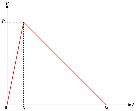
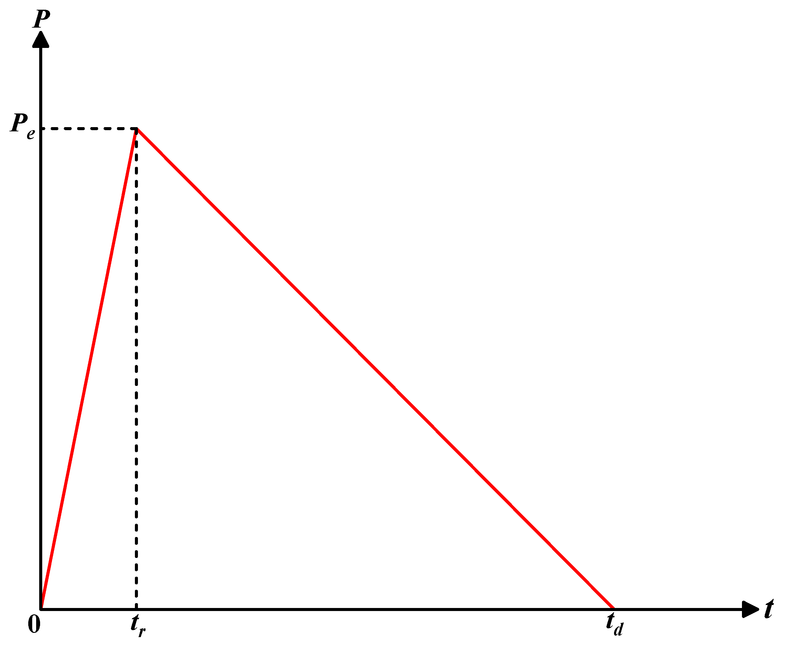
The determination of blasting load is the fundamental prerequisite for analyzing the rock mass blasting fragmentation process and blasting damage evolution process. Existing studies have shown that the rock mass response to blasting load can be well predicted by merely modeling the stress wave effect [31,34]. Borehole pressure is time-dependent, and this property must be taken into account in order to accurately model the dynamic mechanical response of the rock mass. In practical applications, semi-empirical and semi-theoretical formulas are mostly used to describe the variation of blast load with time; trigonometric loading functions are widely used in numerical calculations because of its simplicity and effectiveness. In this paper, a triangular loading function is adopted to simulate approximately the blasthole pressure–time history (Figure 4):
where is the blasthole wall pressure–time history, t is the time, is the total duration of borehole pressure, and is the rising duration of borehole pressure. According to the studies of Zuo et al. [33] and Zhu et al. [35], and used in this paper were chosen to be 100 and 600 μs, respectively.
Figure 4.
Blasting load exerted on the borehole wall.
4.2. Description of the Damage Constitutive Model for Ore and CTB
The RHT model is a tension-compression damage model proposed by three scholars, namely Riedel, Hiermaier, and Thoma, on the basis of the HJC model. By introducing the third invariant of the deviatoric stress tensor to qualitatively determine the material strain type and stress state, the model overcomes the shortcoming of the HJC model in inadequately characterizing tensile stress damage [36]. In blasting applications, the propagation of cracks in the fractured zone is dominated by tensile stress; therefore, obvious drawbacks would arise if the HJC model were adopted. For this reason, the RHT model is selected in this paper.
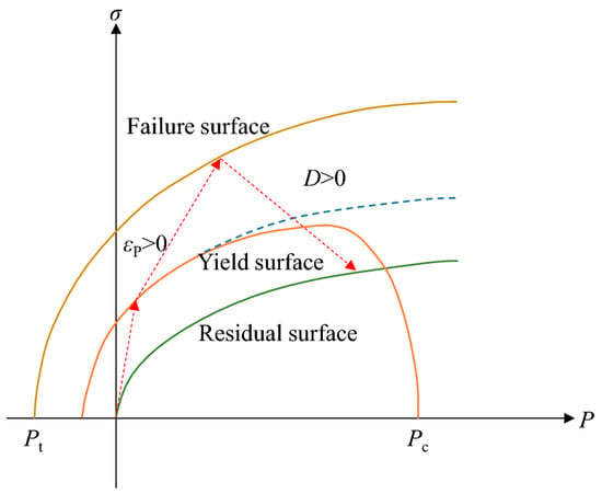
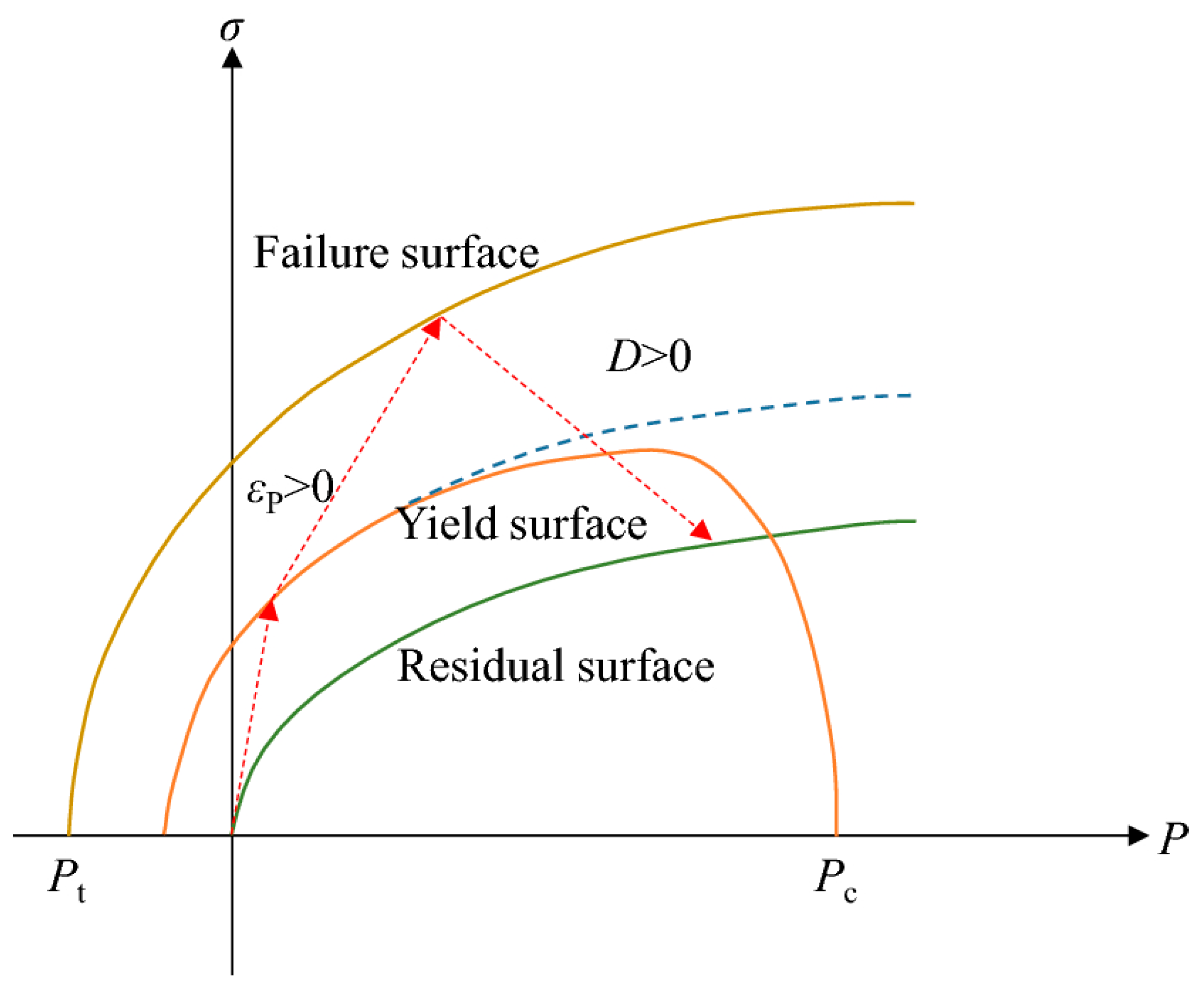
Compared with existing damage models, the RHT model takes into account the effects of confining pressure, strain rate, strain hardening, and damage softening on the failure strength of rock materials under blasting and dynamic loading conditions. In the RHT material model, the strength model is described by three limit surfaces, namely the yield surface, the failure surface, and the residual strength surface, the schematic diagram of which is shown in Figure 5. According to the model parameter determination method proposed by Li et al. [37], the RHT model parameters of ore and filling body are obtained and listed in Table 3 and Table 4, respectively.
Figure 5.
Stress limit surfaces and loading scenario of the RHT model.
Table 3.
RHT model parameters for ore.
Table 4.
RHT model parameters for CTB.
4.3. Numerical Model of Blasting Damage Control of CTB
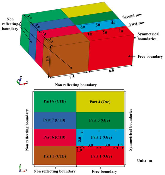
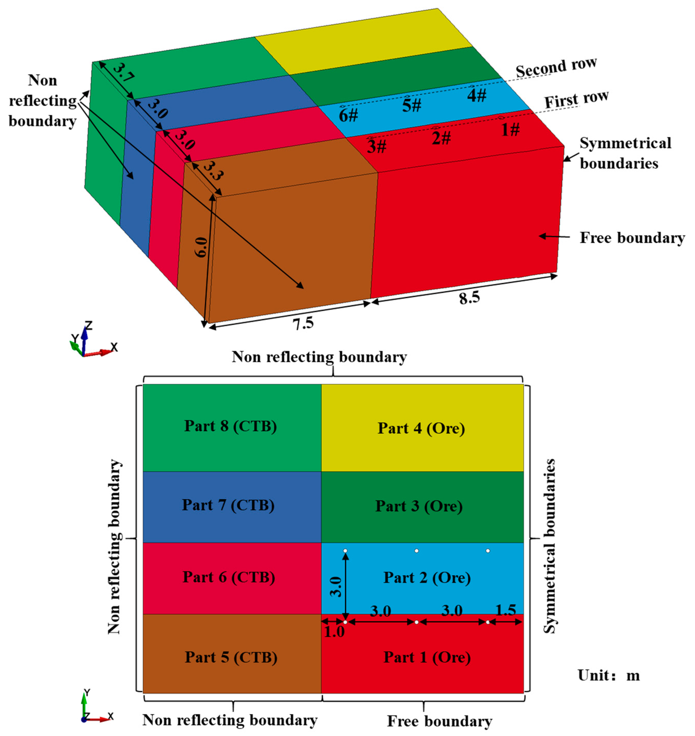
Constrained by the charge quantity per blasting event, the number of blastholes detonated in each round of stope blasting is usually no more than two rows. To this end, a semi-symmetric numerical model was established in this study to simulate the blasting process of two rows of blastholes. As shown in Figure 6, the overall dimensions of the model are 16 m × 13 m × 6 m. Given the considerable length of the blastholes and the consistent charge structure along the Z-direction, symmetric boundary conditions were applied to both the top and bottom of the model to reduce the model size and improve computational efficiency. The boundary condition settings of the model are shown in Figure 6. The average size of the model elements is 6 cm × 6 cm × 6 cm, and the total number of elements is approximately 3.5 million.
Figure 6.
Schematic diagram of the numerical model.
When simulating the blasting of the rear row, it is necessary to adjust the charge structure repeatedly. To ensure that the state variables such as blasting stress, displacement, and damage induced by the front-row blasting in rock mass elements can be inherited in the calculation of the rear row, the small restart technique was adopted in this study. Meanwhile, the excavated rock mass part of the front row was removed using the DELETE_PART command. Based on the above methods, the continuous simulation of the blasting of two rows of blastholes was realized.
In addition, to reduce blasting vibration, the hole-by-hole initiation method was adopted for the blasting of the second-step stope. Studies have shown that rock mass blasting damage is mainly formed within 3 ms after detonation. Therefore, the initiation delay time between blastholes in the same row was set at 3 ms, and the total simulation duration for each row of blasting was 12 ms.
5. Blasting Parameter Optimization Based on SU-CBD
5.1. The Blasting Damage Characteristics in the First Row
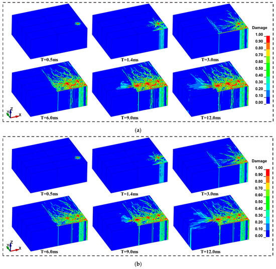
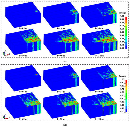
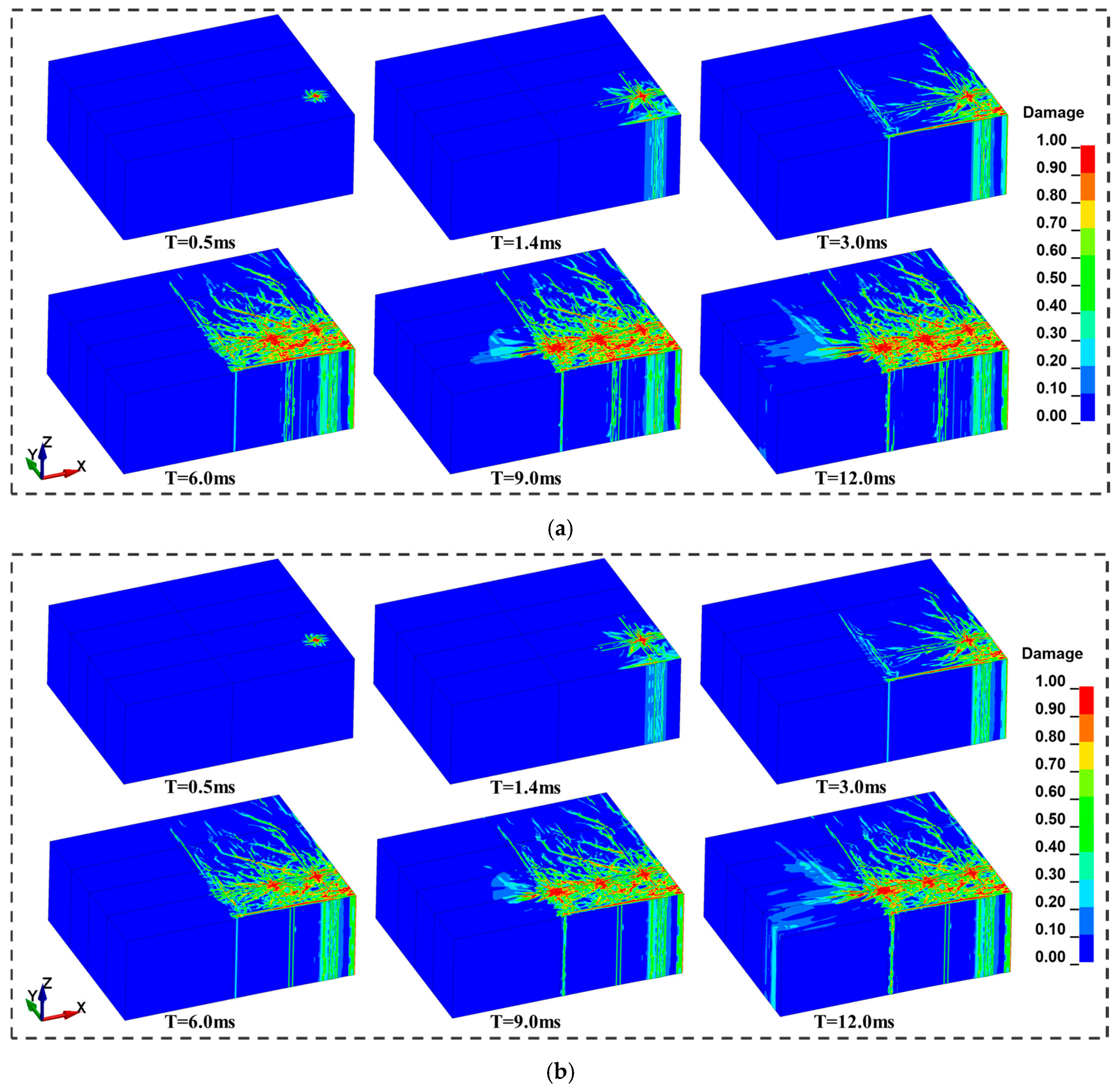
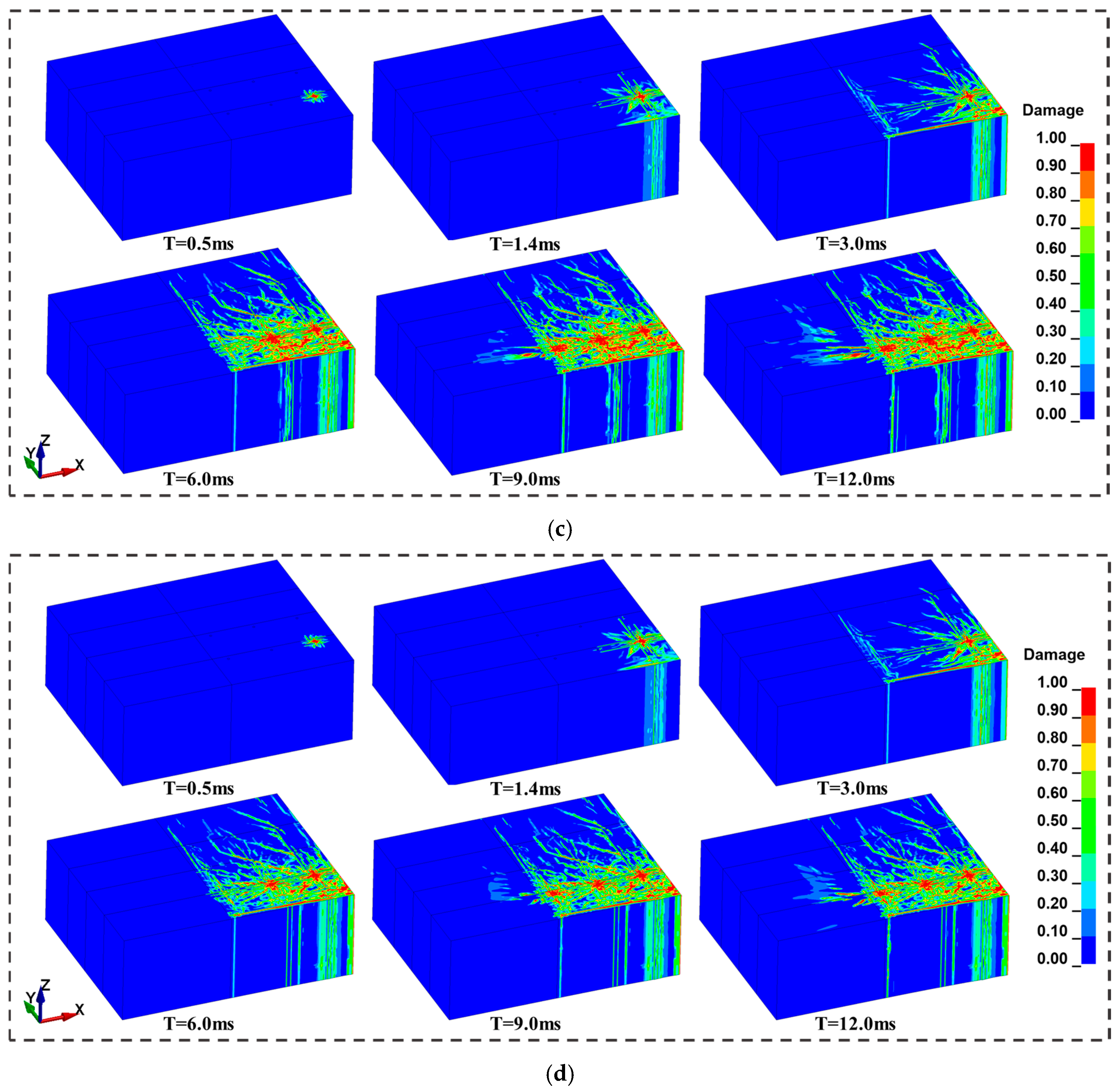
During the blasting of the first row of blastholes, the rock mass remains intact without being disturbed by blasting from other holes. Therefore, to ensure the rock fragmentation effect, it is necessary to appropriately increase the powder factor. With reference to the mine’s practical experience, four schemes were designed, and the charge structure of blastholes for each scheme is presented in Table 5. Based on the predefined charge structures, a numerical simulation study was carried out on the blasting process of the first row of blastholes. Figure 7 shows the blasting damage evolution process under different schemes. The damage evolution processes of the different schemes are quite similar: at t = 0.5 ms, the shock wave action results in the formation of a crushed zone in the rock surrounding the blastholes; by t = 1.4 ms, the compressive stress wave propagates to the free face and is reflected to generate tensile waves, causing tensile damage to the rock mass near the free face; subsequently, the stress waves undergo multiple reflections and continuous oscillations between the blastholes and the free face, and the rock mass damage further expands under the action of alternating tensile and compressive stresses. The blasting damage evolution of the three blastholes in the first row basically stabilizes at approximately 3 ms, 6 ms, and 12 ms, respectively. As can be seen from Figure 7, the damage induced by the blasting of the first row of blastholes has fully covered Part 1, indicating a favorable fragmentation degree of the rock mass in this area. In addition, several scattered damage zones appear in Parts 2 to 6, while no obvious damage is observed in Parts 7 and 8.
Table 5.
Charging structure scheme for the first row of boreholes.
Figure 7.
Blasting damage processes of different schemes: (a) scheme No. 1; (b) scheme No. 2; (c) scheme No. 3; (d) scheme No. 4.
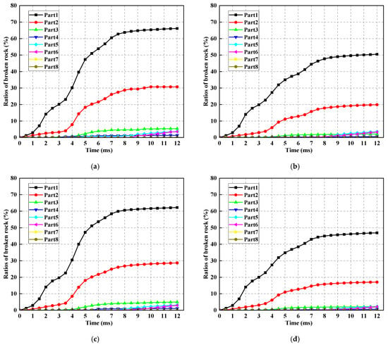
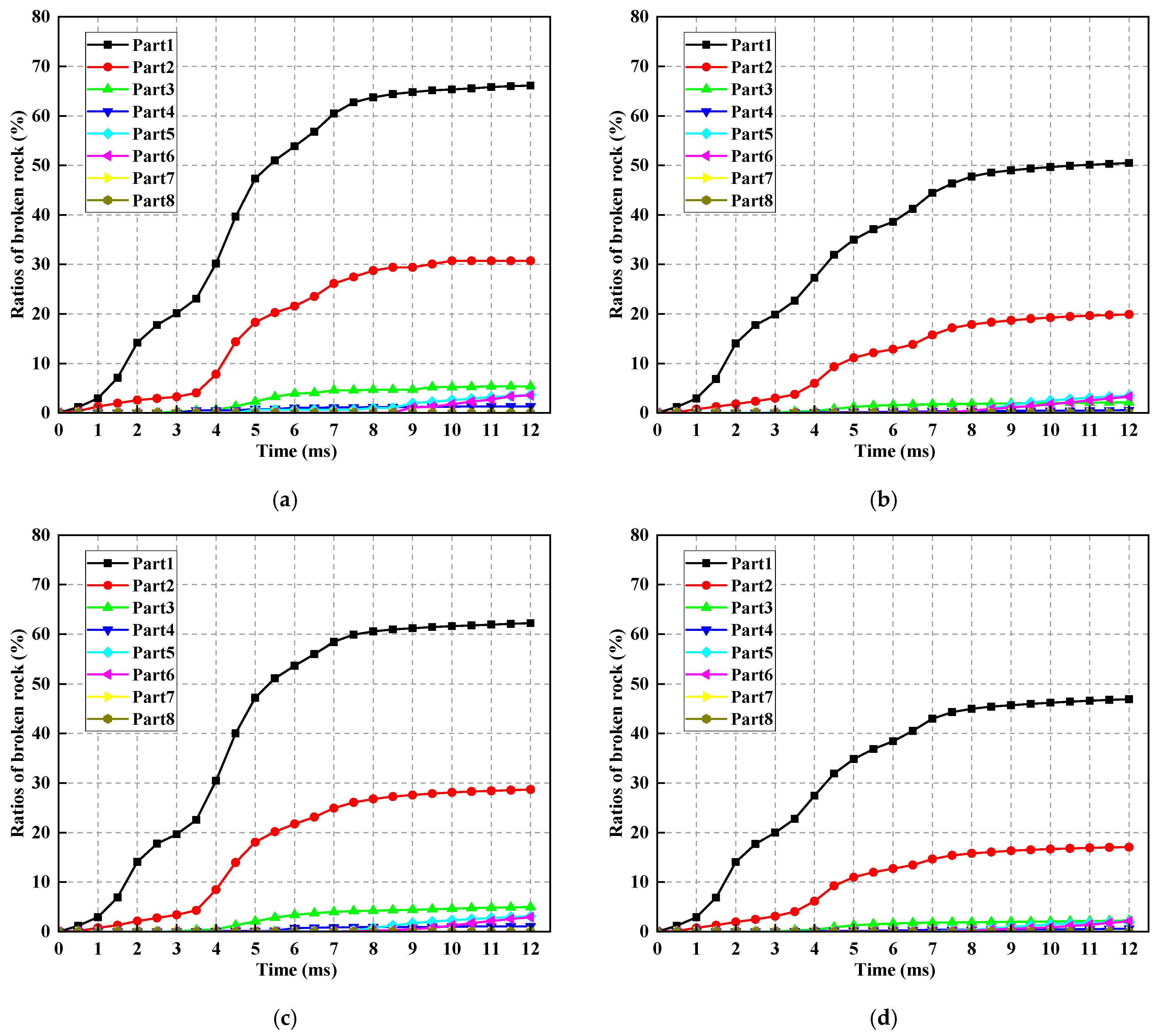
To accurately characterize the rock fragmentation state, the elements with a damage value higher than 0.6 were defined as fragmented rock mass, while the remaining elements were regarded as unfragmented rock mass [38,39]. The rock fragmentation ratios of each part under the four schemes were statistically analyzed, and the curves depicting the variation of fragmentation ratio with time were plotted, as shown in Figure 8. According to Figure 8, it can be seen that due to the larger charge coefficient and total explosion energy, at 12.0 ms, the ratios of broken rock in Part 1 of scheme No. 1 and scheme No. 3 are larger. At 3.0 ms, the ratios are 20.12%, 19.87%, 19.68%, and 20.07% in schemes No. 1, No. 2, No. 3, and No. 4, respectively, and the difference between all the schemes is small. At 6.0 ms, the ratios are 53.85%, 38.58%, 53.68%, and 38.43%, respectively, and the difference between scheme No. 1 and No. 2 is 15.27%, that between scheme No. 1 and No. 3 is 0.17%, and that between scheme No. 2 and No. 4 is 0.15%. At 12.0 ms, the ratios are 69.10%, 50.48%, 62.23%, and 46.94%, respectively, and the difference between scheme No. 1 and No. 2 is 18.62%, that between scheme No. 1 and No. 3 is 6.87%, and that between scheme No. 2 and No. 4 is 3.54%. It can be found that the difference between all the schemes is gradually increasing. This is probably because the blast energy difference between the various schemes is gradually widening.
Figure 8.
Time−history curves of ratios of broken rock for four schemes: (a) scheme No. 1; (b) scheme No. 2; (c) scheme No. 3; (d) scheme No. 4.
By comparison, scheme No. 1 and scheme No. 3 can ensure the breaking effect of rock in the excavation zone; therefore, the optimal charge structure scheme was selected from schemes No. 1 and No. 3. In order to ensure that the selected charge structure scheme causes less blasting damage to the CTB, a detailed comparison of the blast damage to the CTB induced by scheme No. 1 and scheme No. 3 was conducted below. At 12.0 ms, the ratios of broken rock in Part 5, Part 6, Part 7, and Part 8 of scheme No. 1 are 3.66%, 3.56%, 0.015%, and 0.00%, respectively. At 12.0 ms, the ratios of broken rock in Part 5, Part 6, Part 7, and Part 8 of scheme No. 3 are 3.13%, 3.01%, 0.015%, and 0.00%, respectively. From the comparison above, it can be seen that there is not much difference in the ratios of broken rock in CTB caused by schemes No. 1 and No. 3.
In addition, numerous micro-cracks can occur during the blasting process, and these microstructures can eventually affect the integrity of the CTB and reduce its strength. Therefore, in order to visualize the blasting damage on the CTB more, the damage degree () of CTB is defined as:
where is the damage value, is the volume corresponding to the damage value , and is the total volume of CTB element.
According to calculations, the damage degree () of CTB induced by scheme No. 1 and scheme No. 3 is 0.084 and 0.079, respectively.
It can be seen that both scheme No. 1 and scheme No. 3 can ensure a good rock breaking effect and small blasting damage to the CTB. However, scheme No. 1 has a higher blasting energy, which can cause greater damage to the rocks in Part 2, thereby reducing the powder factor in that area. This helps to minimize over-break and reduce damage to the CTB. Therefore, scheme No. 1 is the optimal charge structure for the boreholes in the first row.
5.2. The Blasting Damage Characteristics in the Second Row
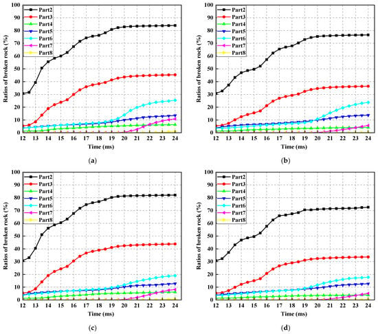
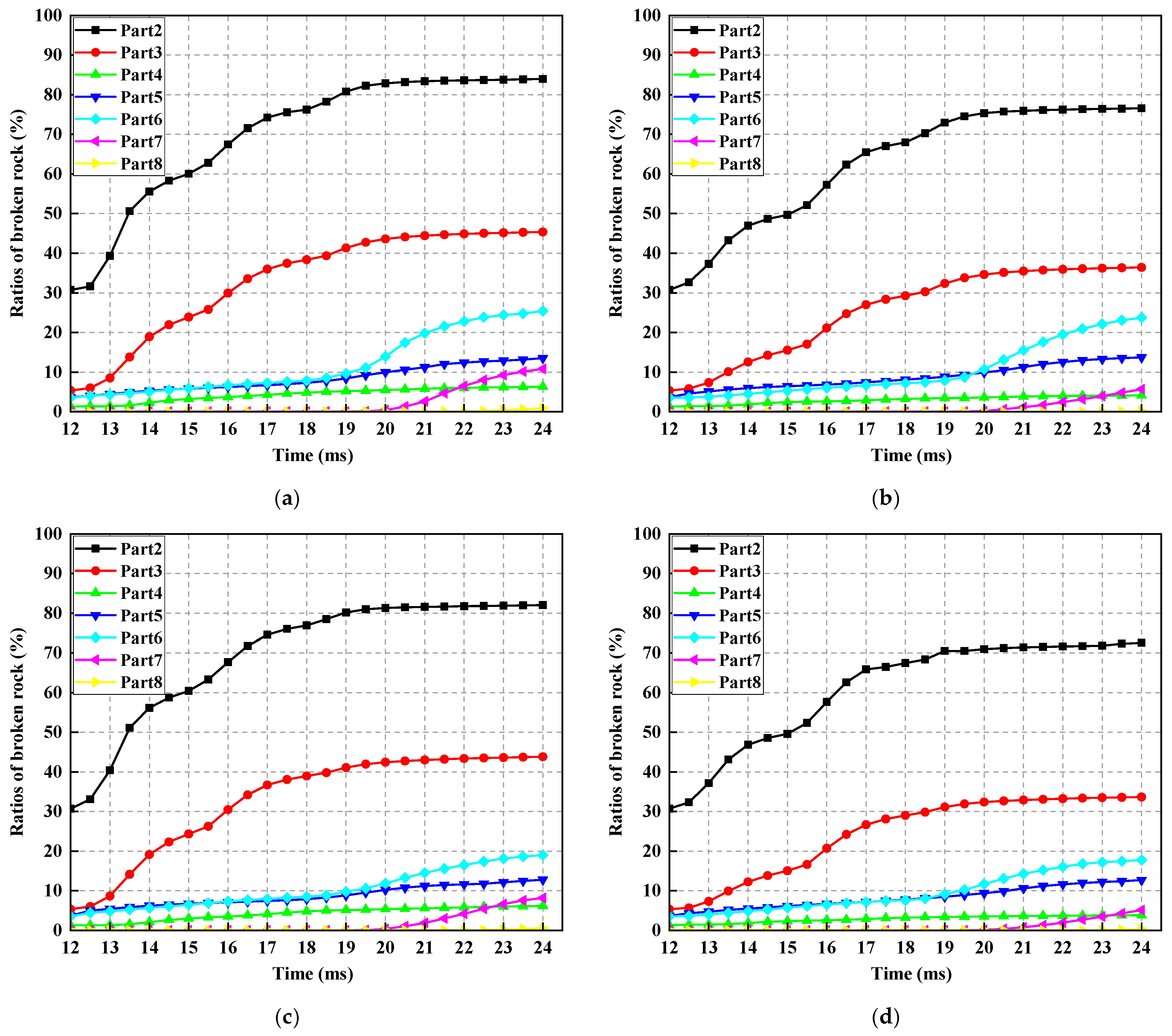
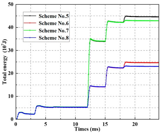
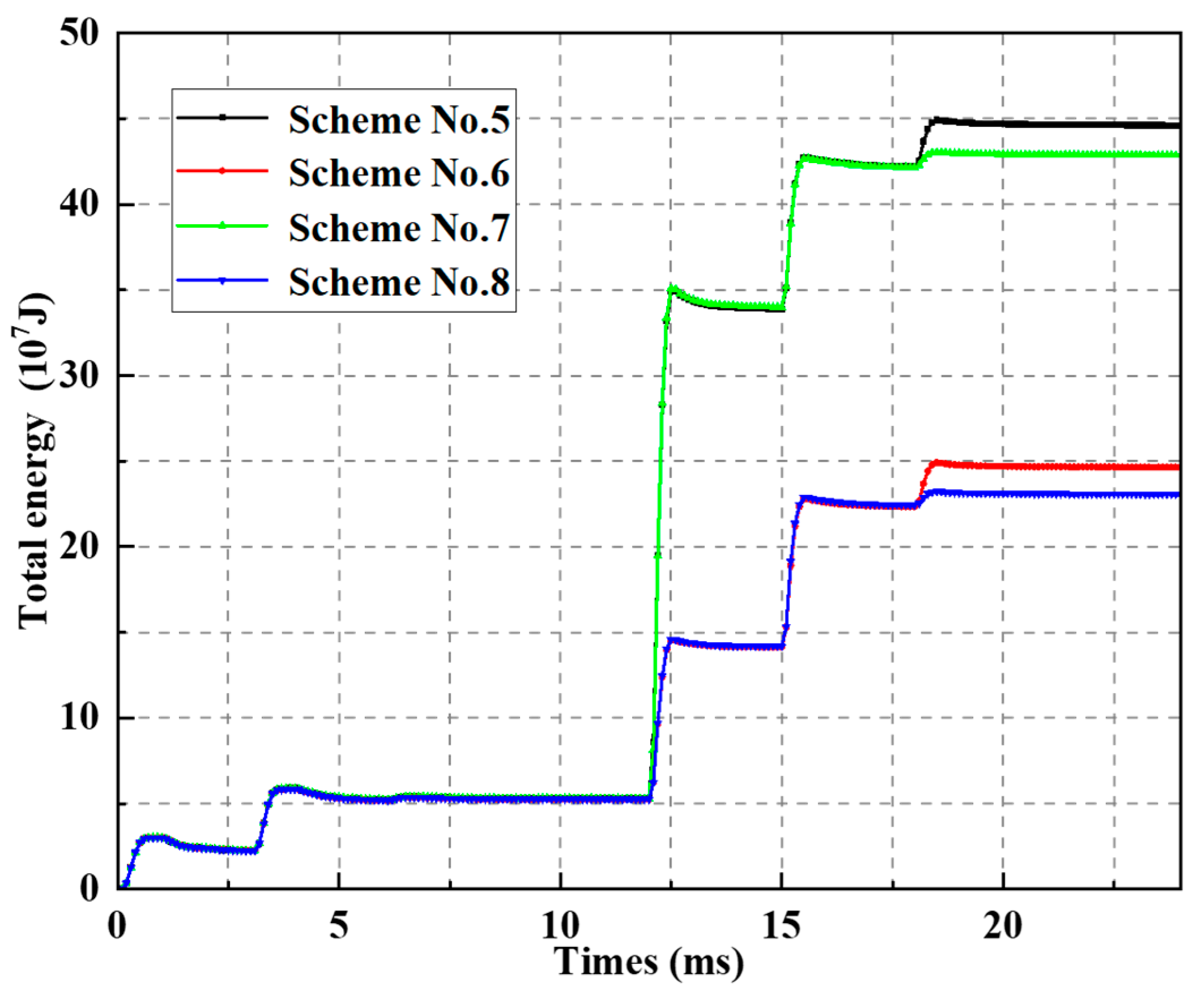
Considering that the blasting of the first row of blastholes already caused certain blasting damage to the rock mass in Part 2, the charge coefficient of the second row of blastholes could be appropriately reduced. Four schemes were designed for the second row of blastholes, and the charge structure of blastholes for each scheme is presented in Table 6. Based on the blasting simulation results of Scheme 1, the small restart technique was adopted to simulate Schemes 5–8. Figure 9 shows the time−history curves of rock fragmentation ratios in different parts for Schemes 5–8. At the moment of 24.0 ms, the rock fragmentation ratios in Part 2 for Schemes 5 to 8 were 83.95%, 76.57%, 82.02%, and 72.56%, respectively. This indicates that all four schemes can effectively fragment the rock mass in the excavation zone; however, Schemes 5 and 7 yield relatively higher rock fragmentation ratios, which may lead to severe overbreak issues. Figure 10 presents the time−history curves of total energy in Part 2 for Schemes 5–8. As can be seen from the figure, the total energy of Schemes 5 and 7 is much higher than that of Schemes 6 and 8, and the energy difference is far greater than the difference in their rock fragmentation ratios. This suggests that most of the energy of Schemes 5 and 7 is consumed in forming the blasting crushed zone, which not only reduces the blasting energy utilization efficiency of Schemes 5 and 7, but also generates a large amount of fine ore and increases ore loss. Therefore, Schemes 6 and 8 are superior to Schemes 5 and 7.
Table 6.
Charging structure scheme for the second row of boreholes.
Figure 9.
Time−history curves of ratios of broken rock for four schemes: (a) scheme No. 5; (b) scheme No. 6; (c) scheme No. 7; (d) scheme No. 8.
Figure 10.
Time−history curves of total energy in Part 2 for schemes No. 5 to 8.
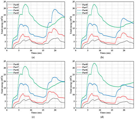
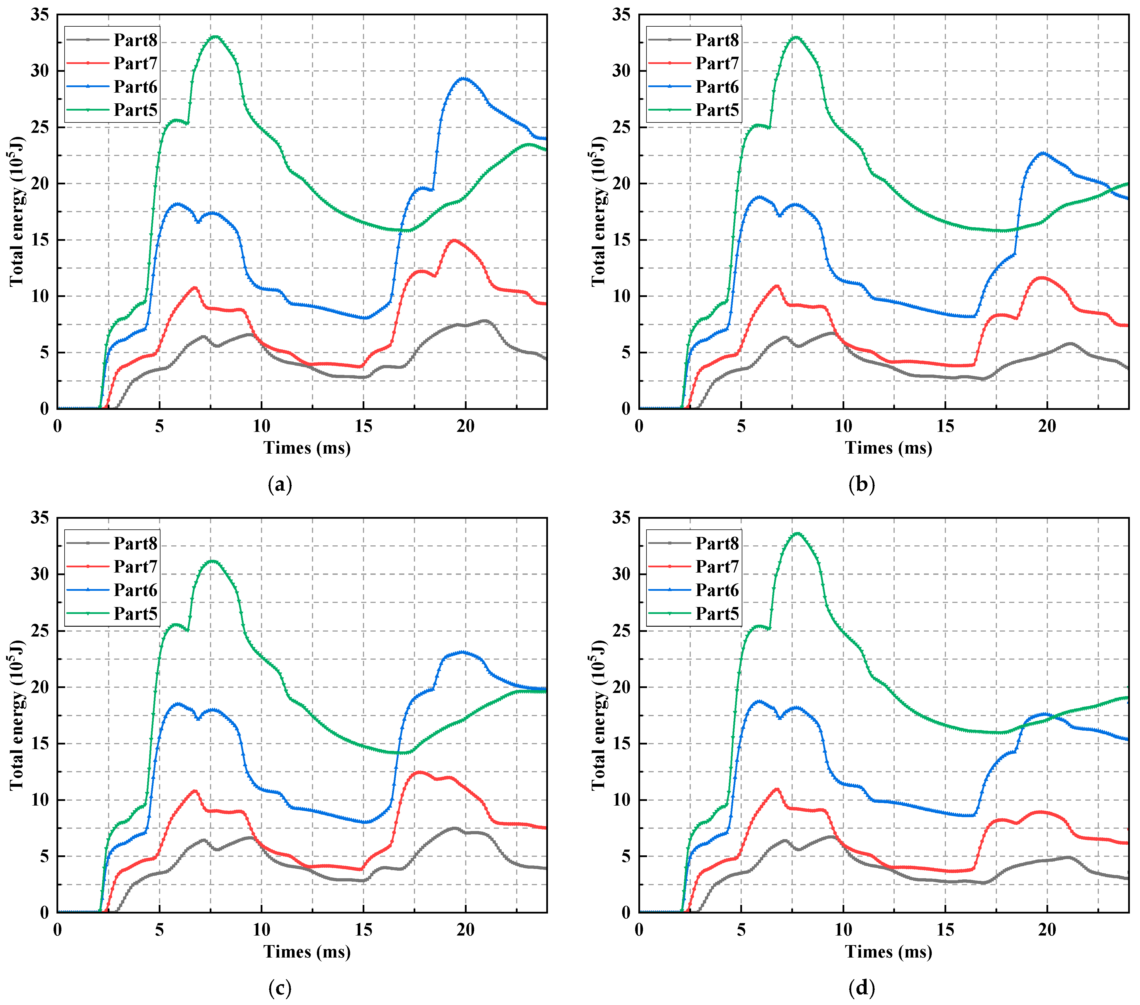
Figure 11 shows the time−history curves of total energy of CTB for Schemes 5–8. It can be observed from Figure 11 that the differences in the peak total energy among the schemes are insignificant in Parts 5, 7, and 8. This is because Parts 5, 7, and 8 are far away from the second row of blastholes and thus less affected by the blasting of the second row. The peak total energy in Part 6 is most significantly affected by the blasting schemes, and the order of peak total energy for each scheme is as follows: Scheme 5 > Scheme 7 > Scheme 6 > Scheme 8. This indicates that Scheme 8 transfers the least energy to CTB and causes the minimum damage to CTB. It is worth noting that the charge coefficient of the boundary hole in Scheme 6 is significantly higher than that in Scheme 7. This implies that the traditional CTB damage control technology, which only reduces the charge amount of boundary holes, has drawbacks. A reasonable damage control technology should comprehensively consider the charge structures of all blastholes. Meanwhile, the damage degree () of CTB for each scheme was also calculated. According to calculations, the damage degree () of CTB induced by schemes No. 5, No. 6, No. 7, and No. 8 is 0.271, 0.227, 0.225, and 0.162, respectively.
Figure 11.
Time−history curves of total energy in CTB for schemes No. 5 to 8: (a) scheme No. 5; (b) scheme No. 6; (c) scheme No. 7; (d) scheme No. 8.
In summary, scheme No. 8 is superior to the other schemes in terms of blasting energy utilization efficiency, fine ore rate control, and CTB damage control. Therefore, scheme No. 8 is the optimal charge structure scheme for the second row of blastholes.
5.3. Optimized Borehole Row Spacing
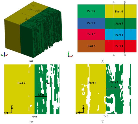
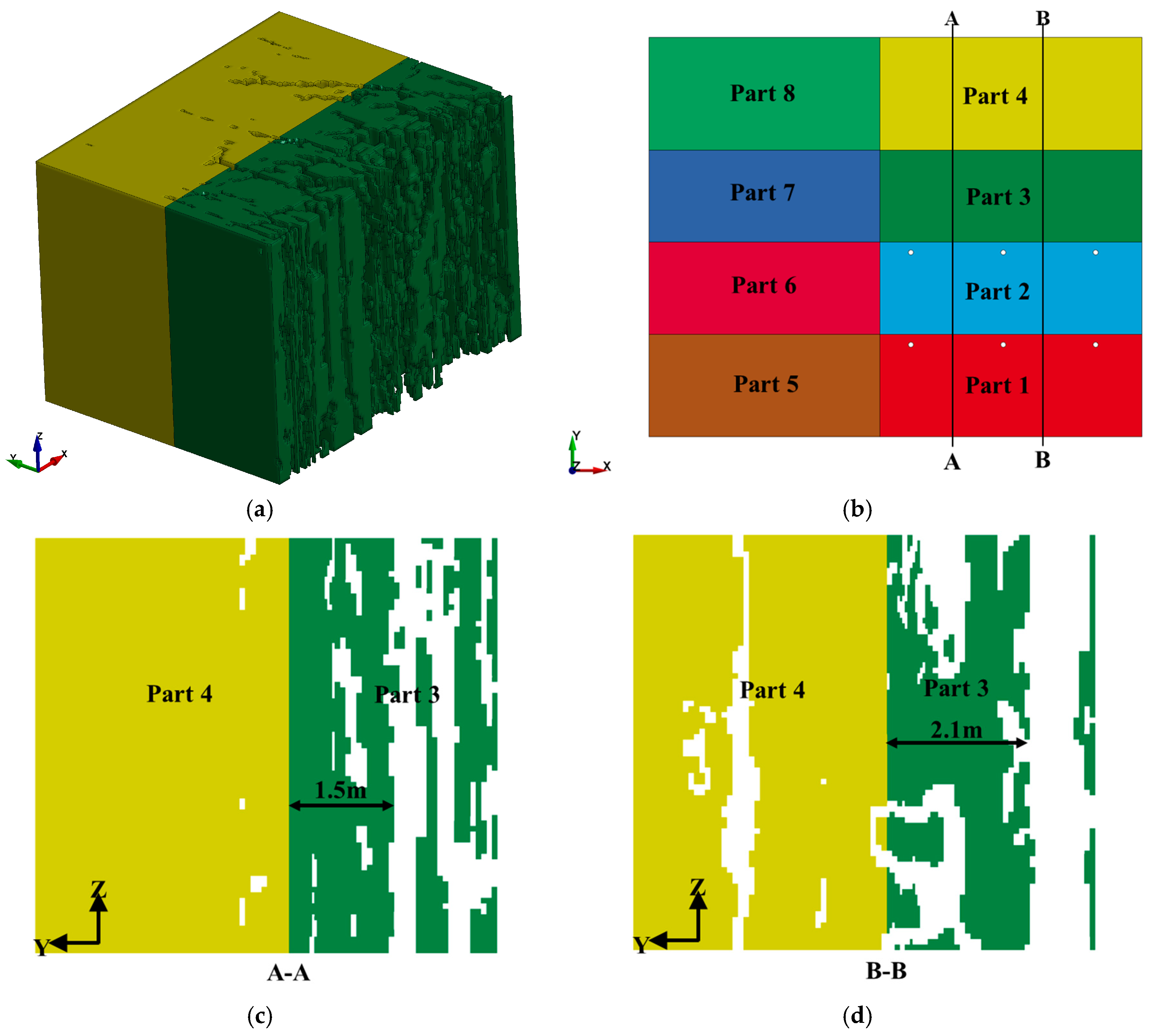
As mentioned previously, constrained by the explosive charge per blasting event, the number of blasthole rows detonated in each round of stope blasting is generally no more than two. Consequently, multiple blasting operations are required for a single stope. The preceding blasting often causes damage to the retained rock mass (Part 3), which in turn leads to overbreak. The overbreak phenomenon will reduce the minimum burden for subsequent blasting, thereby compromising operational safety and blasting energy utilization efficiency. To ensure operational safety and improve explosive energy utilization efficiency, it is essential to appropriately increase the minimum burden for subsequent blasting, namely, to enlarge the row spacing of blastholes.
Figure 12a presents the three-dimensional breaking pattern of remaining rock mass for scheme No. 8 at 24.0 ms. The results show that Part 3 has a large amount of broken rock due to the impact of the previous blasting, which will result in a smaller burden and reduces the face-to-goaf safety distance when Part 3 is blasted. To evaluate the accurate extent and the burden width of remaining rock mass, two cuts are selected, as shown in Figure 12b. Figure 12c,d shows the profiles of the simulated rock breaking pattern at cut A-A and cut B-B, respectively. The results show that the burden width of the remaining rock mass in Part 3 is between 1.5 m and 2.1 m. Therefore, the row spacing of the boreholes between the two blasts should be appropriately increased by 0.9 m to 1.5 m. Excessive burden will lead to a poor blasting effect, so in this study, in order to ensure the blasting effect of each borehole, the row spacing of the boreholes between the two blasts was increased by 1.0 m.
Figure 12.
Remaining rock mass breaking pattern at 24.0 ms for scheme No. 8: (a) three-dimensional breaking pattern of remaining rock mass; (b) section layout for evaluating the remaining rock mass breaking effect; (c) remaining rock mass breaking pattern at cut A-A; (d) remaining rock mass breaking pattern at cut B-B.
6. Field Test
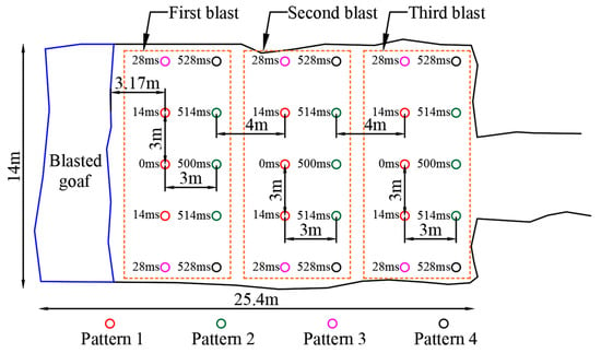
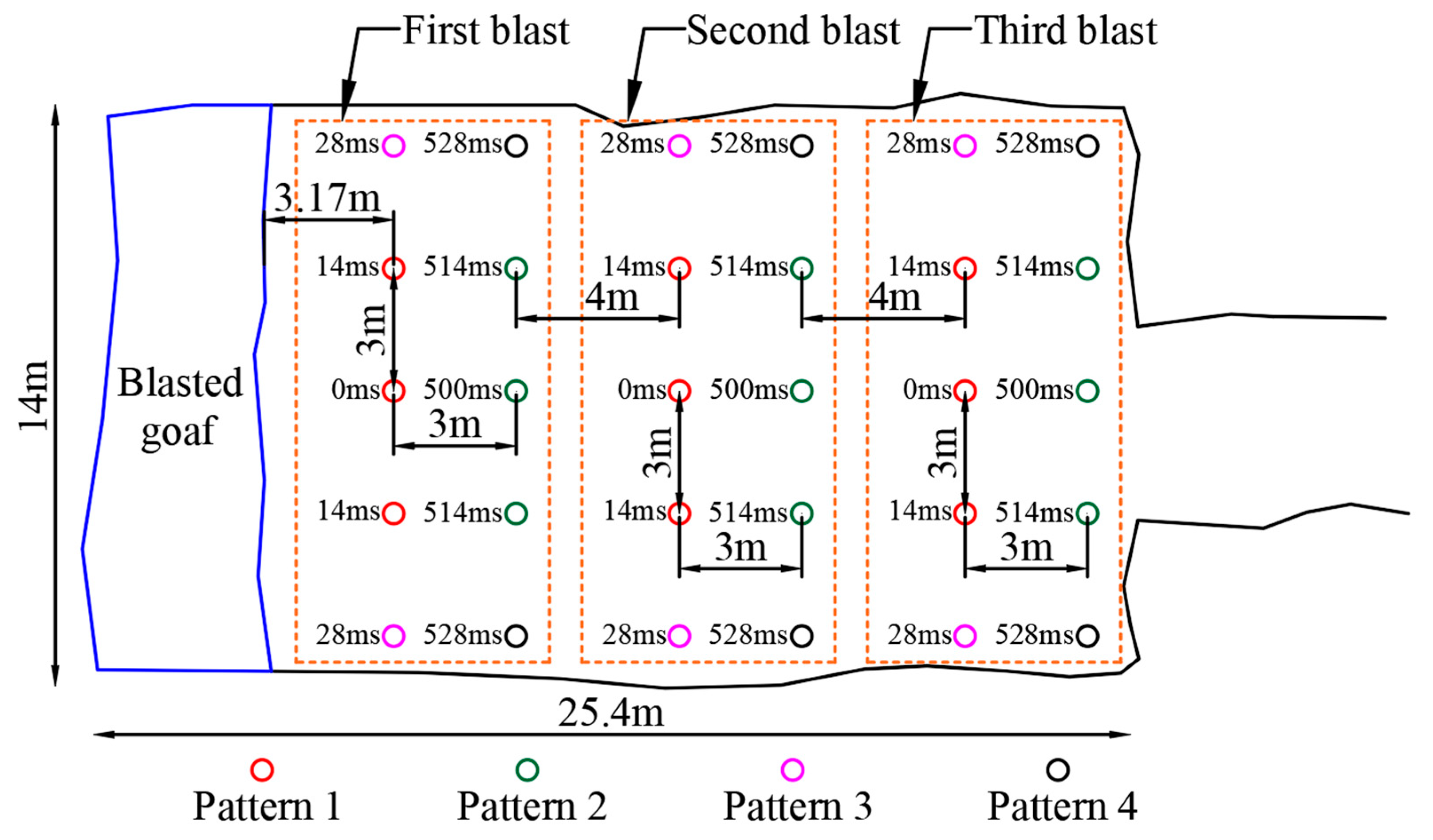
Based on the recommended blasting parameters in Section 5, field blasting tests were carried out in the Bangzhong Mining Area to verify the feasibility of the SU-CBD technology. Stope No. 5 in the 4500 m–4550 m mining level of Bangzhong Mine was selected as the test site. According to the numerical simulation results, the blasting parameters of the test stope were designed, as shown in Figure 13. In the tests, bamboo tubes with a diameter of approximately 140 mm were used instead of air decks; concrete plugs were adopted for hole-bottom stemming, and river sand was used for stemming. The explosive cartridges of adjacent blastholes were arranged in a staggered pattern to reduce the oversize ore ratio after blasting. The blasting of the entire test stope lasted approximately 2 months, including three blasting events, which were conducted on 6 May 2023, 2 June 2023, and 29 June 2023, respectively.
Figure 13.
Blasting design of the test stope.
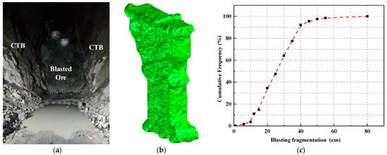
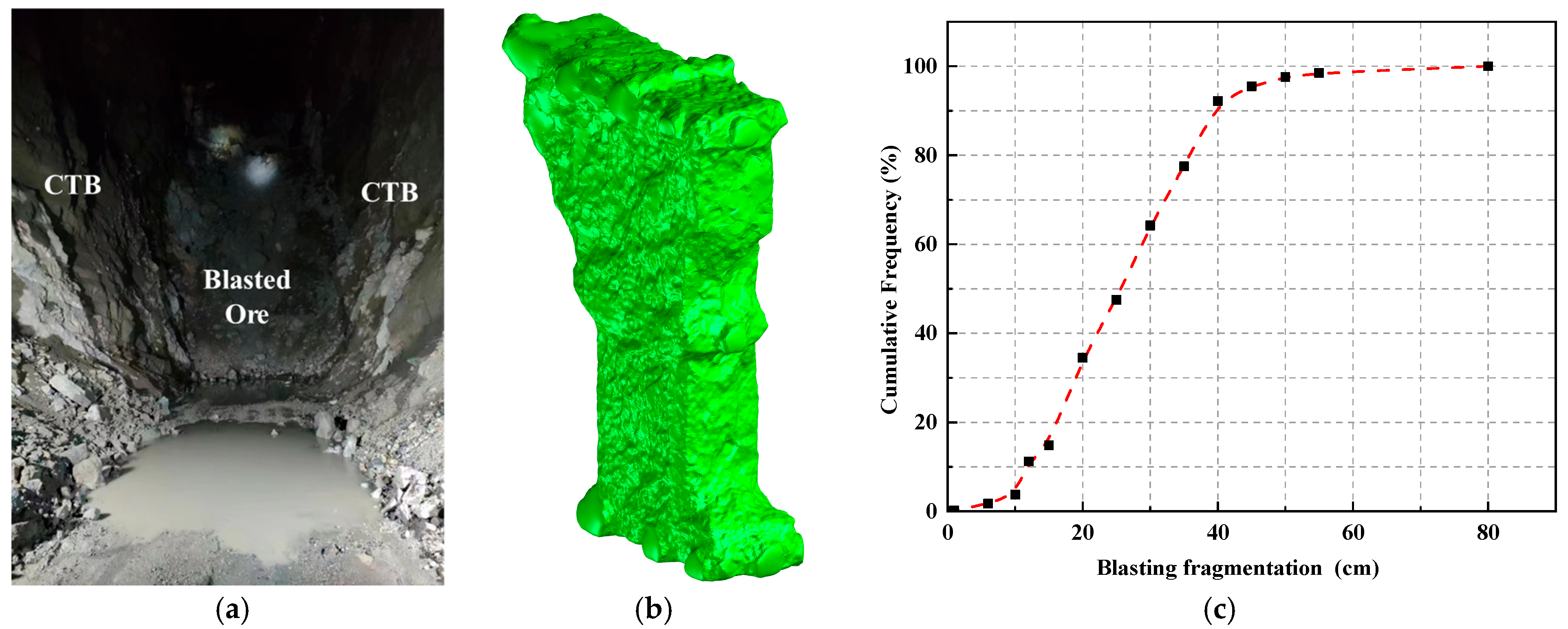
Figure 14a shows the photos of CTB on both sides of the stope after blasting. It can be clearly seen from the photos that the CTB is exposed on the stope walls, featuring good integrity without large-scale collapse. Figure 14b presents the 3D laser scanning results of the goaf in the test stope; as indicated in the figure, the morphology of the goaf is basically consistent with the designed stope morphology. Figure 14c shows the distribution curve of blasting fragmentation sizes in the test stope. It can be seen from the figure that the fragmentation sizes of the caved ore are relatively uniform, with the oversize ore ratio (particle size > 50 cm) reaching 2.4%, which is far lower than the mine’s critical value of 5%. Therefore, from the perspective of field industrial tests, the numerical simulation results are in good agreement with the actual production results, and the field tests have verified the feasibility of the SU-CBD technology proposed in this study.
Figure 14.
Field results of the test stope: (a) photograph of CTB; (b) 3D laser scanning results of the goaf; (c) distribution curve of blasting fragmentation size in the test stope.
7. Discussion
7.1. Action Mechanism of the SU-CBD Technology
(1) Traditional research on CTB blasting damage control mostly focuses on the instantaneous dynamic response of a single blasting event, while ignoring the damage accumulation effect caused by multiple blasting operations during actual stoping. For the first time, this paper introduces the rock mass damage accumulation theory into charge structure optimization and proposes the new SU-CBD technology. By taking full advantage of the improved blastability of pre-damaged rock mass, this technology reduces the charge quantity per hole and blasting vibration while ensuring favorable fragmentation effect. The rationality and effectiveness of the SU-CBD technology have been verified by numerical simulation and field tests.
(2) The research results show that the traditional method of only reducing the charge amount of boundary holes is difficult to effectively control filling body damage. For example, the charge coefficient of boundary holes in Scheme 6 is significantly higher than that in Scheme 7, yet the blasting energy transmitted to the filling body is lower than that in Scheme 7. This indicates that reasonable CTB blasting damage control should be a process of systematic optimization, which needs to comprehensively consider the charge structures of all blastholes.
(3) The RHT material model combined with the small restart technique can effectively capture the cumulative damage evolution process of multi-row blasting, and the triangular loading function can reasonably simulate the blasting load on the borehole wall.
(4) The field tests carried out in the Bangzhong Zinc-Copper Mine show that the optimized blasting parameters can effectively control CTB damage, maintain its structural stability and achieve a favorable ore fragmentation effect simultaneously. This provides a referenceable blasting design example for mines with similar steeply inclined and thick ore bodies, which adopt the sublevel open stoping with a subsequent filling method. In particular, the dynamic row spacing adjustment method proposed in this paper has practical guiding significance in terms of blasting vibration control and overbreak prevention.
7.2. Methodological Limitations
(1) The RHT model parameters for ore and CTB in this paper (Table 3 and Table 4) were determined based on laboratory physical and mechanical tests (Table 1 and Table 2) and existing literature methods, without on-site dynamic test calibration for the study area. However, the numerical simulation results in the original paper were highly consistent with the field test results, which verified the rationality of the parameter selection. For follow-up research, further precise calibration can be conducted by combining with on-site blasting vibration monitoring data.
(2) In this study, the numerical simulation assumed that both the CTB and ore were homogeneous and isotropic materials. This assumption was made on the premise that the ore in the Bangzhong Zinc-Copper Mine has poorly developed joints and the CTB exhibits low spatial variability in strength and performance, which is consistent with the conventional simplification methods for engineering research. However, for mines with well-developed rock joints and severe CTB stratification, the material heterogeneity and anisotropy must be fully considered.
(3) Based on the engineering background of Bangzhong Zinc-Copper Mine, the original paper neglected the influence of in situ stress on blasting. This assumption is only applicable to mining conditions with shallow depth and low in situ stress. For deep mines with high in situ stress, it is necessary to incorporate the in situ stress field into the numerical model and consider the coupling effect between in situ stress and blasting stress.
(4) The core principle of the SU-CBD technology lies in improving rock mass blastability through the accumulation of blasting damage, thereby achieving various technical objectives. Therefore, if the damage variable of the rock mass changes little under blasting disturbance, the SU-CBD technology may fail in such cases. In the application of this technology, techniques such as acoustic wave testing can be adopted to determine the variation degree of the rock mass damage variable under blasting disturbance, so as to judge the effectiveness of the SU-CBD technology.
(5) The parameters of the SU-CBD technology should be adjusted for different rock mass conditions, and the technical parameters in this paper are only for reference by mines with similar engineering conditions.
8. Conclusions
8.1. Theoretical Conclusions
(1) Cumulative blasting damage leads to progressive degradation of rock mechanical properties, enhancing blastability, as the fractured zone radius of the rock mass increases with the rise of damage variable D, and the peak radial stress at the ore−CTB interface decreases simultaneously.
(2) Incorporating the cumulative effect of rock mass damage into the charge design system can reduce the powder factor and diminish the blasting energy transmitted to the cemented tailings backfill (CTB).
8.2. Engineering Conclusions
(1) A dynamic adjustment method for blasthole row spacing with an optimal increment of 1.0 m can effectively solve the problems of retained rock mass damage and overbreak caused by multiple blasting.
(2) Field industrial tests in the Bangzhong Zinc-Copper Mine verify that the SU-CBD technology can keep the CTB intact without collapse and achieve an oversize ore ratio of only 2.4%, and the numerical simulation results are in good agreement with the field results
(3) Systematic optimization of the charge structure of all blastholes is more effective for CTB damage control than the traditional method of only reducing the charge of boundary holes.
Author Contributions
Conceptualization, J.S., S.Q., and X.Z.; methodology, J.S. and X.Z.; software, J.S. and S.Q.; validation, J.S., S.L., and H.L.; data curation, J.S. and Z.S.; writing—original draft, J.S. and S.Q.; supervision, X.Z.; funding acquisition, X.Z. All authors have read and agreed to the published version of the manuscript.
Funding
This work was supported by the National Natural Science Foundation of China (Key Program, Grant No. 52130403); the National Science and Technology Major Project for Deep Earth: Refined and Efficient Mining Technologies for Complex and Hard-to-Extract Strategic Mineral Resources (Grant No. 2024ZD1003801); and the Fundamental Research Funds for the Central Universities (Major Demand Project, Grant No. N2301027).
Institutional Review Board Statement
Not applicable.
Informed Consent Statement
Not applicable.
Data Availability Statement
The raw data supporting the conclusions of this article will be made available by the authors on request.
Conflicts of Interest
The authors declare no conflicts of interest.
References
- Li, P.; Cai, M.F. Challenges and new insights for exploitation of deep underground metal mineral resources. Trans. Nonferrous Met. Soc. China 2021, 31, 3478–3505. [Google Scholar] [CrossRef] [Scilit]
- Huang, L.Q.; Wang, Z.W.; Liu, K.; Liu, H.L.; Li, M.J.; Shen, H.M.; Li, X.B. Damage distribution characteristics and space optimizations of the large-diameter deep multi-holes blasting in thick ore bodies. Tunn. Undergr. Space Technol. 2025, 156, 106264. [Google Scholar] [CrossRef] [Scilit]
- Emad, M.Z.; Mitri, H.; Kelly, C. Effect of blast-induced vibrations on fill failure in vertical block mining with delayed backfill. Can. Geotech. J. 2014, 51, 975–983. [Google Scholar] [CrossRef] [Scilit]
- Qiu, H.J.; Qiu, X.Y.; Zhang, S.; Shi, X.Z.; Tao, M.; Cao, R.H.; Cao, M.Y. Study on the damage pattern of the cemented backfill at the jagged rock-fill interface under dynamic loading of blasting. J. China Coal Soc. 2025, 50, 2037–2050. [Google Scholar] [CrossRef]
- Trigueros, E.; Cánovas, M.; Arzúa, J.; Baraibar, J. Evaluating the influence of backfilling on the stability of an abandoned room-and-pillar mine: A case study in northern Spain. Geomech. Geophys. Geo-Energy Geo-Resour. 2024, 10, 116. [Google Scholar] [CrossRef] [Scilit]
- Emad, M.Z.; Mitri, H.S.; Henning, J.G. Effect of blast vibrations on the stability of cemented rockfill. Int. J. Min. Reclam. Environ. 2012, 26, 233–243. [Google Scholar] [CrossRef] [Scilit]
- Li, G.W.; Deng, G.Z.; Ma, J.G. Numerical modelling of the response of cemented paste backfill under the blasting of an adjacent ore stope. Constr. Build. Mater. 2022, 343, 128051. [Google Scholar] [CrossRef] [Scilit]
- Song, X.P.; Fan, B.W.; Wang, S.; Zhang, H.W. Reloading mechanical characteristics of cemented tailings backfill after dynamic loading action. J. China Coal Soc. 2024, 49, 4785–4797. [Google Scholar] [CrossRef]
- Yao, B.J.; Niu, M.Y.; Zeng, L.F.; Guo, W.K.; Lin, R.Z.; Lou, X.M. Study on Edge Hole Spacing based on Stress Field of Deep Hole Delay Blasting. Blasting 2024, 41, 51–59. [Google Scholar]
- Tan, Y.Y.; Yu, X.; Elmo, D.; Xu, L.H.; Song, W.D. Experimental study on dynamic mechanical property of cemented tailings backfill under SHPB impact loading. Int. J. Miner. Metall. Mater. 2019, 26, 404–416. [Google Scholar] [CrossRef] [Scilit]
- Liu, B.; Gao, Y.T.; Jin, A.B.; Wang, X. Dynamic characteristics of superfine tailings-blast furnace slag backfill featuring filling surface. Constr. Build. Mater. 2020, 242, 118173. [Google Scholar] [CrossRef] [Scilit]
- Cao, S.; Yilmaz, E.; Song, W.D. Dynamic response of cement-tailings matrix composites under SHPB compression load. Constr. Build. Mater. 2018, 186, 892–903. [Google Scholar] [CrossRef] [Scilit]
- Liu, Z.X.; Li, X.B. Research on Stability of High-level Backfill in Blasting. Min. Metall. Eng. 2004, 24, 21–24. [Google Scholar]
- Fan, L.F.; Wang, L.J.; Wu, Z.J. Wave transmission across linearly jointed complex rock masses. Int. J. Rock Mech. Min. Sci. 2018, 112, 193–200. [Google Scholar] [CrossRef] [Scilit]
- Li, X.F.; Li, H.B.; Li, J.C.; Li, Z.W. Research on Transient Wave Propagation Across Nonlinear Joints Filled with Granular Materials. Rock Mech. Rock Eng. 2018, 51, 2373–2393. [Google Scholar] [CrossRef] [Scilit]
- Hu, Y.G.; Lu, W.B.; Chen, M.; Yan, P.; Yang, J.H. Comparison of Blast-Induced Damage Between Presplit and Smooth Blasting of High Rock Slope. Rock Mech. Rock Eng. 2014, 47, 1307–1320. [Google Scholar] [CrossRef] [Scilit]
- Li, H.B.; Xia, X.A.; Li, J.C.; Zhao, J.A.; Liu, B.; Liu, Y.Q. Rock damage control in bedrock blasting excavation for a nuclear power plant. Int. J. Rock Mech. Min. Sci. 2011, 48, 210–218. [Google Scholar] [CrossRef] [Scilit]
- Liu, K.W.; Li, X.D.; Hao, H.; Li, X.B.; Sha, Y.Y.; Wang, W.H.; Liu, X.L. Study on the raising technique using one blast based on the combination of long-hole presplitting and vertical crater retreat multiple-deck shots. Int. J. Rock Mech. Min. Sci. 2019, 113, 41–58. [Google Scholar] [CrossRef] [Scilit]
- Lu, W.B.; Chen, M.; Geng, X.; Shu, D.Q.; Zhou, C.B. A study of excavation sequence and contour blasting method for underground powerhouses of hydropower stations. Tunn. Undergr. Space Technol. 2012, 29, 31–39. [Google Scholar] [CrossRef] [Scilit]
- Zeng, Y.Q.; Li, H.B.; Xia, X.; Liu, B.; Zuo, H.; Jiang, J.L. Blast-induced rock damage control in Fangchenggang nuclear power station, China. J. Rock Mech. Geotech. Eng. 2018, 10, 914–923. [Google Scholar] [CrossRef] [Scilit]
- Zhao, Y.; Yang, R.S.; Zuo, J.J.; Liu, Z.; Wang, W.L. Dynamic response characteristics of backfill under blasting disturbance simulated through a three-dimensional model. Constr. Build. Mater. 2024, 443, 137685. [Google Scholar] [CrossRef] [Scilit]
- Huang, X.C.; Lu, W.B.; Zhang, L.X.; Yan, P.; Shi, L. Study on Blasting Vibration Failure Mechanism and Vibration Velocity Threshold of Total Tailing Cemented Backfill. Blasting 2021, 38, 1–7. [Google Scholar]
- Emad, M.Z.; Mitri, H.; Kelly, C. Dynamic model validation using blast vibration monitoring in mine backfill. Int. J. Rock Mech. Min. Sci. 2018, 107, 48–54. [Google Scholar] [CrossRef] [Scilit]
- Suazo, G.; Villavicencio, G. Numerical simulation of the blast response of cemented paste backfilled stopes. Comput. Geotech. 2018, 100, 1–14. [Google Scholar] [CrossRef] [Scilit]
- Wu, Y.S.; Zhao, Y.Q.; Chen, S.J.; Jin, A.B.; Qin, W.J. Study on vibration attenuation and damage characteristics of adjacent filling bodies under blasting effects. J. Mater. Res. Technol.-JMRT 2025, 39, 3370–3388. [Google Scholar] [CrossRef] [Scilit]
- Zhao, Y. Dynamic Response and Damage Control Technology of Filling Body Under Blast Loading. Ph.D. Thesis, University of Science and Technology Beijing, Beijing, China, 2023. [Google Scholar]
- Huo, X.F.; Shi, X.Z.; Qiu, X.Y.; Zhou, J.; Gou, Y.G.; Yu, Z.; Ke, W.Y. Rock damage control for large-diameter-hole lateral blasting excavation based on charge structure optimization. Tunn. Undergr. Space Technol. 2020, 106, 103569. [Google Scholar] [CrossRef] [Scilit]
- Wang, H.C.; Wang, Z.L.; Wang, J.G.; Wang, S.M.; Wang, H.R.; Yin, Y.G.; Li, F. Effect of confining pressure on damage accumulation of rock under repeated blast loading. Int. J. Impact Eng. 2021, 156, 103961. [Google Scholar] [CrossRef] [Scilit]
- Ji, L.; Zhou, C.B.; Lu, S.W.; Jiang, N.; Gutierrez, M. Numerical Studies on the Cumulative Damage Effects and Safety Criterion of a Large Cross-section Tunnel Induced by Single and Multiple Full-Scale Blasting. Rock Mech. Rock Eng. 2021, 54, 6393–6411. [Google Scholar] [CrossRef] [Scilit]
- Ji, L.; Zhou, C.B.; Lu, S.W.; Jiang, N.; Li, H.B. Modeling study of cumulative damage effects and safety criterion of surrounding rock under multiple full-face blasting of a large cross-section tunnel. Int. J. Rock Mech. Min. Sci. 2021, 147, 104882. [Google Scholar] [CrossRef] [Scilit]
- Lu, W.B.; Yang, J.H.; Chen, M.; Zhou, C.B. An equivalent method for blasting vibration simulation. Simul. Model. Pract. Theory 2011, 19, 2050–2062. [Google Scholar] [CrossRef] [Scilit]
- Li, S.L.; Ling, T.L.; Liu, D.S.; Liang, S.F.; Zhang, R.; Huang, B.; Liu, K. Determination of Rock Mass Parameters for the RHT Model Based on the Hoek-Brown Criterion. Rock Mech. Rock Eng. 2023, 56, 2861–2877. [Google Scholar] [CrossRef] [Scilit]
- Zuo, S.Y.; Xiao, M.; Xv, J.K.; Shi, W.B. Numerical simulation of dynamic damage effect of surrounding rocks for tunnels by blasting excavation. Rock Soil Mech. 2011, 32, 3171–3176+3184. [Google Scholar] [CrossRef]
- Ling, T.L.; Li, S.L.; Liu, D.S.; Liang, S.F. Blasting Damage of Tunnel Rock Mass Based on Cumulative Effect. Rock Mech. Rock Eng. 2023, 56, 1679–1695. [Google Scholar] [CrossRef] [Scilit]
- Zhu, W.C.; Wei, C.H.; Li, S.; Wei, J.; Zhang, M.S. Numerical modeling on destress blasting in coal seam for enhancing gas drainage. Int. J. Rock Mech. Min. Sci. 2013, 59, 179–190. [Google Scholar] [CrossRef] [Scilit]
- Wang, Z.L.; Wang, H.C.; Wang, J.G.; Tian, N.C. Finite element analyses of constitutive models performance in the simulation of blast-induced rock cracks. Comput. Geotech. 2021, 135, 104172. [Google Scholar] [CrossRef] [Scilit]
- Li, H.C.; Chen, Y.; Liu, D.S.; Huang, Y.H.; Zhao, L. Sensitivity Analysis Determination and Optimization of Rock RHT Parameters. Trans. Beijing Inst. Technol. 2018, 38, 779–785. [Google Scholar] [CrossRef]
- Yi, C.P.; Sjöberg, J.; Johansson, D. Numerical modelling for blast-induced fragmentation in sublevel caving mines. Tunn. Undergr. Space Technol. 2017, 68, 167–173. [Google Scholar] [CrossRef] [Scilit]
- Yi, C.P.; Sjöberg, J.; Johansson, D.; Petropoulos, N. A numerical study of the impact of short delays on rock fragmentation. Int. J. Rock Mech. Min. Sci. 2017, 100, 250–254. [Google Scholar] [CrossRef] [Scilit]

Disclaimer/Publisher’s Note: The statements, opinions and data contained in all publications are solely those of the individual author(s) and contributor(s) and not of MDPI and/or the editor(s). MDPI and/or the editor(s) disclaim responsibility for any injury to people or property resulting from any ideas, methods, instructions or products referred to in the content. |
© 2026 by the authors. Licensee MDPI, Basel, Switzerland. This article is an open access article distributed under the terms and conditions of the Creative Commons Attribution (CC BY) license.