


Abstract
During the high-intensity mining of shallow-buried thick coal seams, the formation of a water-conducting fracture zone within the overburden is a primary cause of damage to the groundwater system. To address the challenge of balancing efficiency and cost in traditional water-retaining mining methods, this study proposes and validates a trapezoidal strip filling mining technology based on the “span reduction effect”. By developing a mechanical model of a four-sided simply supported thin plate representing the key layer, the fundamental mechanism of the filling body was elucidated. This mechanism involves the active adjustment of the support boundary, which effectively reduces the force span of the key layer. Furthermore, leveraging the fourth-power relationship (w ∝ a4) between deflection and span, the bending deformation of the overburden rock is exponentially mitigated. This study employs a four-tiered integrated verification system comprising theoretical modeling, physical simulation, numerical simulation, and engineering field testing: First, theoretical calculations indicate that reducing the effective span of the key layer by 40% can decrease its maximum deflection by 87%. Second, large-scale physical similarity simulations predict that implementing this filling method can significantly control the height of the water-conducting fracture zone, reducing it from 94 m under the collapse method to 58 m, which corresponds to a 45.5% reduction in surface settlement. Third, FLAC3D numerical simulations further elucidated the mechanical mechanism by which the backfill system transforms stress distribution from “coal pillar-dominated bearing capacity” to “synergistic bearing capacity of backfill and coal pillars”. Shear failure in the critical layer was suppressed, and the development height of the plastic zone was restricted to approximately 54 m, showing high consistency with physical simulation results. Finally, actual measurements of water injection through the inverted hole underground provide direct evidence: The heights of the water-conducting fracture zones in the filling working face and the collapse working face are 59 m and 93 m, respectively, reflecting a reduction of 36.6%. Based on the consistency between measured and simulated results, the numerical model employed in this study has been effectively validated. Research indicates that employing trapezoidal strip filling technology based on principal stress dynamics regulation can effectively promote a shift in the failure mode of the overlying critical layer from “fracture–conduction” to “bending–subsidence”. This mechanism provides a clear mechanical explanation and predictable design basis for the green mining of shallow coal seams.
1. Introduction
Coal mining in the ecologically fragile northwest China often leads to the leakage of shallow groundwater and the degradation of ecosystems, resulting in a significant “mining–water–ecology” conflict [1,2]. This conflict mainly stems from the upward development of the water-conducting fracture zone during the mining process, which damages the key aquiclude and weakens its water-blocking performance [3]. Therefore, the key to effective water conservation during coal mining lies in accurately controlling the height of the water-conducting fracture zone to ensure the integrity of the aquiclude.
The Ordos Basin in China is rich in coal resources, approximately 70% of which are distributed in arid and semi-arid areas with limited surface water resources [4]. The phreatic aquifer of the Salaurusu Formation is crucial for maintaining the local ecosystem and vegetation [5]. However, its proximity to the shallow coal seams forms a “mining–seepage” interaction system. Mining activities may damage the structure of water-resistant rock layers, leading to ecological disasters such as water level decline and land desertification [6]. Therefore, coordinating the relationship between resource extraction and water resource protection has become a significant challenge for promoting regional sustainable development.
Backfill mining is an effective method for controlling overburden failure and enhancing water conservation effects [7]. Currently, the main techniques include high-intensity backfill (e.g., full goaf backfill) and limited mining (e.g., narrow strip mining, room-and-pillar mining). High-intensity backfill can significantly reduce overburden failure, but its cost is 30–50% higher than that of the caving method [8]. Limited mining restricts rock deformation by controlling the extraction ratio (usually less than 60%), but it tends to cause resource losses [9]. In addition, emerging technologies such as bed separation grouting [10] and the “backfill–direct roof” composite structure [11] still lack a general principle to correlate the spatial layout of the backfill with the mechanical response of key rock strata. This conceptual limitation leads to a design process often relying on trial and error, with unpredictable effects and difficulty in balancing technical effectiveness and economic feasibility.
To this end, this study proposes a trapezoidal strip partial filling method for the shallowly buried and thin-bedrock coal seams in northern Shaanxi based on the principle of “span reduction”. This method optimizes the mechanical boundary conditions of the key strata [12] by constructing trapezoidal filling bodies in the goaf, thereby reducing their effective spans. According to the thin-plate theory, the deflection of the strata is closely related to the span, and reducing the span can significantly decrease the flexural deformation. This technology aims to suppress the crack penetration, optimize the water conservation effect, and minimize the usage of filling materials as much as possible.
To verify the feasibility of this method, the following objectives are set in this study: (1) Establish a mechanical model of the key strata supported by trapezoidal backfill bodies and quantitatively analyze the relationship between backfill parameters, span changes, and deflection suppression. (2) Through physical simulation experiments and numerical simulation experiments, compare the differences between the new method and the traditional caving method in terms of roof rock mass failure and joint development patterns. (3) Conduct on-site measurements using the underground upward-borehole water injection method to obtain direct evidence of the height of the water-conducting fracture zone and construct a comprehensive verification system integrating theory, simulation, and on-site measurement.
This study determined rock mechanical parameters through field investigations and laboratory tests, established a key rock layer mechanical model based on elastic-plate theory, and analyzed its deformation control mechanism. Based on this, a trapezoidal strip filling scheme was designed, and its effectiveness was validated through physical simulation experiments and numerical simulation experiments. Simultaneously, high-altitude in situ observations of the water-conducting fracture zone were conducted underground. Through comprehensive evaluation integrating theoretical analysis, experimental data, and field measurement results, the reliability and engineering applicability of this method were systematically validated.
2. Overview of the Study Area and Project Background
2.1. Hydrogeological Conditions of Guojiawan Coal Mine
Guojiawan Coal Mine is located in the northeastern part of the Ordos Basin. The coal seams in this region generally exhibit gentle anticline and syncline structures, with a dip angle of less than 1°, belonging to typical near-horizontal coal seams. The main coal seam being mined is Coal Seam No. 5, with an average thickness of 4.6 m and a burial depth ranging from 10 to 204 m, featuring typical shallow-burial characteristics.
The primary aquifer within the area is the Q3S (Quaternary Upper Pleistocene Sarausu Formation) confined aquifer, serving as the main source of water for local residents’ daily use, agricultural production, and some industrial purposes. It is primarily replenished by atmospheric precipitation infiltration. Based on borehole exploration and pumping test data, this aquifer has an average thickness of approximately 10.92 m. Its lithology is dominated by fine sandstone with relatively good permeability, exhibiting a permeability coefficient of 1.2 × 10⁻³ cm/s. Unit yield from borehole pumping tests ranges from q = 0.123 to 0.69 L/(s·m). The aquiclude between this aquifer and Coal Seam No. 5 is composed of siltstone with a thickness of about 10 m, which plays a crucial role in suppressing the expansion and penetration of water-conducting fractures caused by mining activities.
2.2. Main Mechanical Parameters
The main physical and mechanical parameters of the rock mass are shown in Table 1. The data in the table are derived from systematic sampling and laboratory tests on the roof and floor rock strata of Coal Seam No. 5. A total of 120 sets of uniaxial compression tests and 45 sets of triaxial shear tests were completed. All tests strictly adhered to the “Standard for test methods of engineering rock masses” (GB/T 50266-2013 [13]) to ensure the reliability of the obtained parameters.
Table 1.
Key physical and mechanical parameters.
3. Theoretical Analysis: Control Mechanism of Key Stratum Based on the Coordination of Span Reduction and Stiffness
3.1. Construction of the Mechanical Model for the Key Stratum
3.1.1. Problem Definition
In the mining of shallow-buried coal seams with thin bedrock, the protection of the overlying aquifer hinges on the stability of the key aquiclude [14]. In traditional caving mining, the excessively large exposure span (a) of the key stratum makes it susceptible to bending and fracturing, which can lead to the formation of a water-conducting fracture zone that extends to the aquifer. The fundamental principle of trapezoidal strip filling technology is to actively modify the mechanical boundary conditions of the key stratum by strategically placing filling strips within the goaf. This approach transforms the failure mode from “large-span bending and breaking” to “small-span elastic/elastoplastic bending”.
3.1.2. Model Simplification
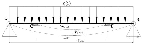
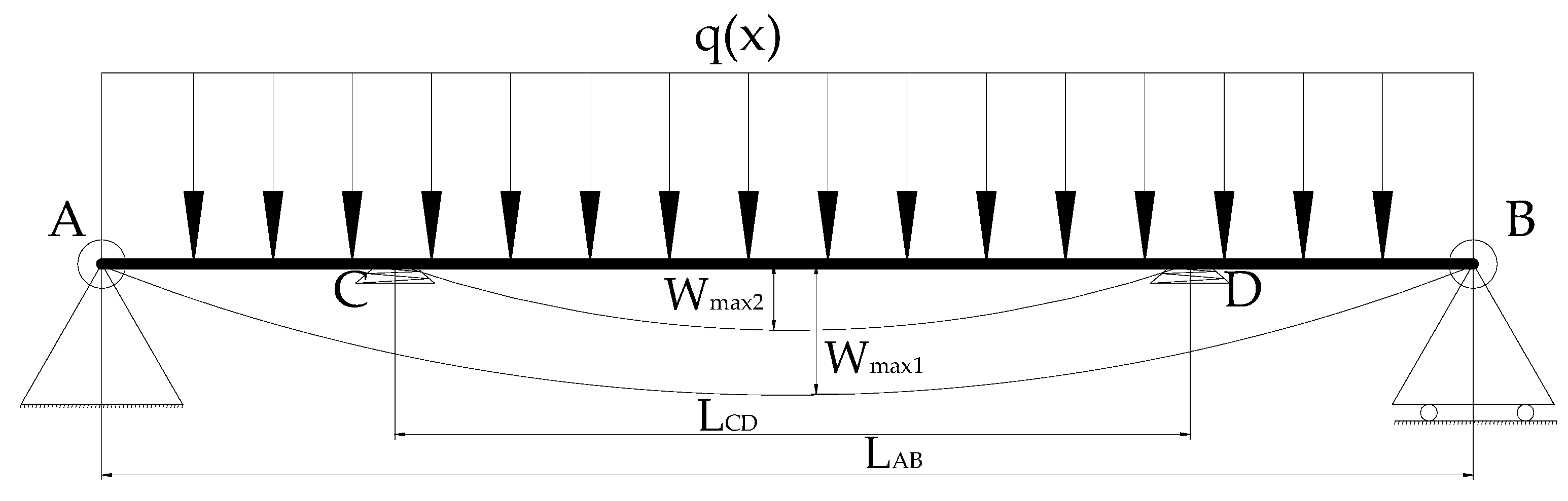
When the thickness of the primary key layer is significantly smaller than its planar dimensions, it can be modeled as an elastic plate. Stress and deformation formulas can then be derived based on fundamental principles of elasticity theory. Initially, the four edges of the thin plate forming the mining face are integrated with the surrounding rock, effectively fixed at all four sides. As the goaf expands and the roof continues to fail, the main key layer in the face’s advance direction can be simplified as a simply supported rectangular thin plate with four edges (Figure 1). For safety considerations, this study adopts a conservative simplification strategy and employs a four-sided simply supported model for analysis [15,16]. In this model: (1) The self-weight of the overlying strata is represented as a uniformly distributed load, denoted as q = γH (where γ is the average bulk density of the overlying strata and H is the vertical distance from the top surface of the key stratum to the ground surface); (2) the mechanical effect of the trapezoidal backfill body is modeled by introducing a pair of elastic supports beneath the thin plate. This adjustment effectively shifts the original support boundaries A and B of the key stratum inward to points C and D, thereby reducing the control span from LAB to LCD (where LAB > LCD). This simplified model serves as the foundational basis for subsequent theoretical analysis.
Figure 1.
A simply supported beam–elastic support model for the key stratum in the strike section of trapezoidal strip filling.
The trapezoidal filling strips create a “wedge-stabilization” effect through the designed sidewall inclination angle (θ), converting part of the vertical load into a horizontal component directed toward the interior of the goaf. This actively enhances slip resistance, effectively compensating for the loss of friction caused by weakened lateral constraints in the roof and floor after mining. Its inclined surface better aligns with the natural angle of repose of collapsed waste rock, promoting synergistic load bearing between the fill and waste rock to uniformly distribute support reaction forces to critical strata. Reducing the angle θ increases the top bearing area and prevents stress concentration, while excessive angles diminish the wedging effect. Optimal control is essential to achieve a balanced equilibrium between stability and load-bearing capacity.
3.2. Analytical Solution for Key Layer Deflection: Utilization of the Fourth-Power Law
According to the small-deflection thin-plate theory in elastic mechanics, the key stratum simply supported on four sides and subjected to a uniformly distributed load q can be simplified into a rectangular thin-plate model. The analytical expression for the maximum central deflection is [17,18]:
where: a is the effective span (m) of the key stratum along the advancing direction of the working face, h is the layer thickness (m), E is the elastic modulus (Pa), μ is the Poisson’s ratio, and q is the equivalent uniformly distributed load (Pa) of the overlying strata. Among them, the flexural rigidity of the plate can be expressed as
This parameter facilitates the reference for subsequent engineering design. As can be seen from Equation (1), the maximum deflection is at the center of the key stratum.
There is a fourth-power proportional relationship between wmax and its effective span a:
Define the effective spans of the key stratum before and after backfilling as a1 and a2 (a2 < a1):
This formula theoretically quantifies the enhancement effect of span reduction on deflection control.
3.3. Quantitative Analysis of Engineering Significance
Using the actual mechanical parameters of the key stratum in Guojiawan Coal Mine (E = 20 GPa, h = 20 m, μ = 0.25, q = 1.45 MPa), a case study on the deflection before and after backfill mining is conducted.
Before backfilling (a1 = 20m): Substituting into Equation (1), we obtain wmax1, approx 67.9 mm. This value exceeds the critical deflection for the tensile rupture of the key stratum, indicating that the key stratum is in a potentially unstable state.
After backfilling (a2 = 12 m): The calculated value of wmax2 is approximately 8.8 mm, which falls within the allowable safety range. The key stratum transitions to a stable bending state.
The calculation results indicate that, when the effective span is reduced by 40% (from 20 m to 12 m), the maximum deflection decreases by 87%. This effect of “minor span adjustment, significant deflection suppression” transforms the key stratum from the “tensile fracture state” under the caving method to the “safe bending state” under the backfilling method. The quartic relationship revealed by Equation (4) provides a quantitative prediction method for the engineering control effect, effectively solving the problem in traditional methods where the control effect is difficult to accurately estimate.
3.4. Synergistic Effect and Design Criteria of Backfill Stiffness
Although the “span reduction” effect reveals the key control mechanism [19], the mechanical behavior of the backfill itself also has a crucial impact. As a compressible medium, its stiffness characteristics and deformation capacity directly determine its supporting effect on the key stratum. Therefore, this study proposes the concept of “stiffness synergy effect,” aiming to construct a complete design framework that integrates both “boundary regulation” and “material response”.
Gradient modulus design: Inspired by the mechanical behavior of natural layered rock masses, this study proposes a controlled gradient distribution of the elastic modulus of the backfill body along the vertical direction (i.e., lower at the top, moderate in the middle, and higher at the bottom). This design facilitates the coordination of the deformation matching between the backfill body and the key stratum and reduces the shear risk at the contact surface, thereby ensuring long-term stability.
Dynamic load sharing: During the compression process, the backfill actively bears part of the overlying load (Δq), reducing the effective load acting on the key stratum to qeff = q − Δq. Substituting into the deflection calculation formula (Equation (1)), it can be seen that the load reduction and the span shortening are coupled with each other, forming a collaborative control mechanism of “active load shedding–passive span limitation”.
Equivalent span increment: The supporting effect of the backfill body can be equivalent to a section of “virtual support length” (ΔL), thereby increasing the critical breaking span of the key stratum from Lc to Lc + ΔL. This not only enhances the engineering fault tolerance of the system but also provides a wider safety time window for on-site construction.
3.5. Mechanism-Driven Standardized Design Process
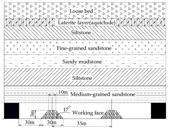
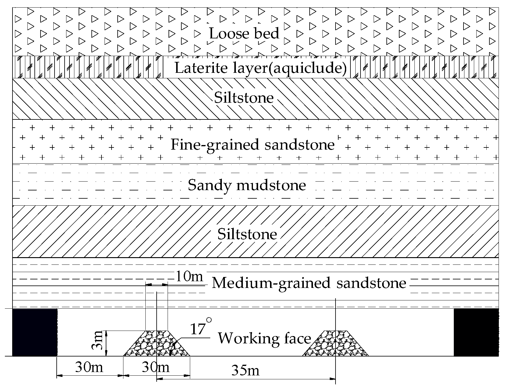
Based on the dual mechanisms of “span reduction–stiffness coordination,” we developed a standardized process that spans parameter identification to performance design (Figure 2). This process marks a paradigm shift from experience-based to mechanism-based approaches.
Figure 2.
Schematic diagram of the trapezoidal strip filling mining scheme.
Step 1: In situ identification of key layer parameters
Using a combined “drilling–testing–measurement” approach, we accurately determined the key stratum’s thickness h, burial depth H, elastic modulus E, Poisson’s ratio μ, and tensile strength σt, as well as the overlying load q, thereby providing a quantitative basis for design.
Step 2: Quantitative determination of the critical state
The critical deflection σt is calculated from wcr and then substituted into Equation (1) to inversely obtain the critical safety span acr, which serves as the core criterion for the self-stability ability of the overlying strata.
Step 3: Optimization of filling strip layout
By comparing the periodic weighting interval of the working face Lp with acr and introducing a safety factor Ks (ranging from 1.5 to 2.0), the center-to-center spacing S of the backfill strips is determined, which must satisfy S ≤ acr/Ks. Then, the strip width is determined according to the designed backfill ratio (60–70%).
Step 4: Collaborative design of filling body performance
Geometric matching: Optimize the trapezoidal slope to ensure dense roof contact and self-stability.
Mechanical matching: The strength of the filling body must satisfy Rc ≥ 1.2γH, and the modulus gradient should be achieved through material proportioning to realize stiffness synergy.
4. Physical Similarity Simulation of Overburden Failure Based on Trapezoidal Strip Backfill Scheme
4.1. Determination of Trapezoidal Strip Backfill Scheme Parameters
4.1.1. Fracture Span According to Key-Stratum Theory
Using the fixed/simply supported beam model and the parameters in Table 1, the initial fracture span of the key stratum is 58 m and the periodic fracture span is 40 m. Considering the actual production conditions in the 5-20102 working face, the initial main-roof weighting interval is 72 m.
4.1.2. Design of Filling Parameters with Safety Reserve
The filling strips must possess sufficient bearing capacity to support the overburden load below the critical layer and resist lateral stress without unstable failure. Appropriately increasing the width of filling strips enhances their roof support function and reduces the height of water-conducting fissures, but this also correspondingly increases the consumption of filling materials and associated costs. Furthermore, the development of water-conducting fissure zones exhibits a positive correlation with surface settlement.
The spacing S between strips should be less than the minimum value of the initial pressure step Lf and the periodic pressure step Lp during full caving mining, S < min(Lf, Lp). This ensures the roof between two filling strips does not sustain a continuous fracture under overburden load. Reducing strip spacing better controls roof failure and significantly suppresses fracture development height. Conversely, this increases filling material consumption and cost.
The strength σc of the backfill body should be sufficient to bear the overburden load below the critical layer, with a certain safety factor. When the strength is adequate, it can effectively limit roof separation and fracturing, reducing the height of the water-conducting fracture zone. When the strength is insufficient, the backfill body undergoes unstable failure, causing a sudden increase in the development height of water-conducting fractures.
To account for mine pressure variability (±15%) and a 10% strength reduction of the filling body after 6 months, we adopt a safety factor of 0.5. Based on this reserve, the trapezoidal filling parameters are set as follows: Strike length 35 m (half of the average breaking span of 65 m), longitudinal filling rate 65% (selected to balance material use and control effectiveness). The filling material consists of a paste with approximately 80% concentration, formulated from gangue, fly ash, binding agents, and mine water. The filling system is located at ground level, and the prepared paste slurry is conveyed through pipelines to the working face support roadways. It solidifies into a consolidated mass with stable mechanical properties within about 28 days, including an elastic modulus of 0.2 GPa, a Poisson’s ratio of 0.3, an internal friction angle of 30°, a density of 1800 kg/m3, and a uniaxial compressive strength of 3.5 MPa [20].
4.1.3. Design of Comparative Mining Schemes
Two comparative schemes were designed. Scheme 1—trapezoidal strip filling (Working face 1502)—has a strike length of 125 m, a dip length of 200 m, a mining height of 4.6 m, and a filling interval of 35 m; paste filling is used with a water–cement ratio of 0.8. Scheme 2—full-seam caving (Working face 1501)—covers an area of 200 m × 200 m and employs full-seam mining with roof control by caving. A 30 m protective coal pillar separates Working face 1501 and Working face 1502.
4.2. Physical Similarity Simulation Experiment Design
4.2.1. Experiment Objectives
This experiment performs large-scale physical similarity simulations to achieve two objectives [21,22,23]. First, it tests the theoretical mechanisms of “span reduction” and “stiffness synergy” for scientific validity [24]. Second, it quantitatively assesses how the trapezoidal strip filling scheme (strip width 35 m, filling rate 65%) influences key-stratum fracturing and the development of the water-conducting fracture zone (WCFZ). By directly comparing overlying rock failure modes under the traditional caving method (Working face 1501) and the trapezoidal strip filling method (Working face 1502), the study provides an experimental basis for engineering application.
4.2.2. Similarity Criteria and Model Construction
The experiment follows similarity theory and establishes a precise “prototype–model” mapping so that simulation results can be directly used to infer in situ operating conditions. The similarity relations are derived from the π theorem, and the key similarity constants are specified (Table 2). In particular, the stress similarity constant is obtained by combining the geometric similarity constant with the bulk density similarity constant, thereby satisfying the requirements of rock mass mechanical similarity.
Table 2.
Similarity parameters.
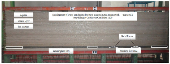
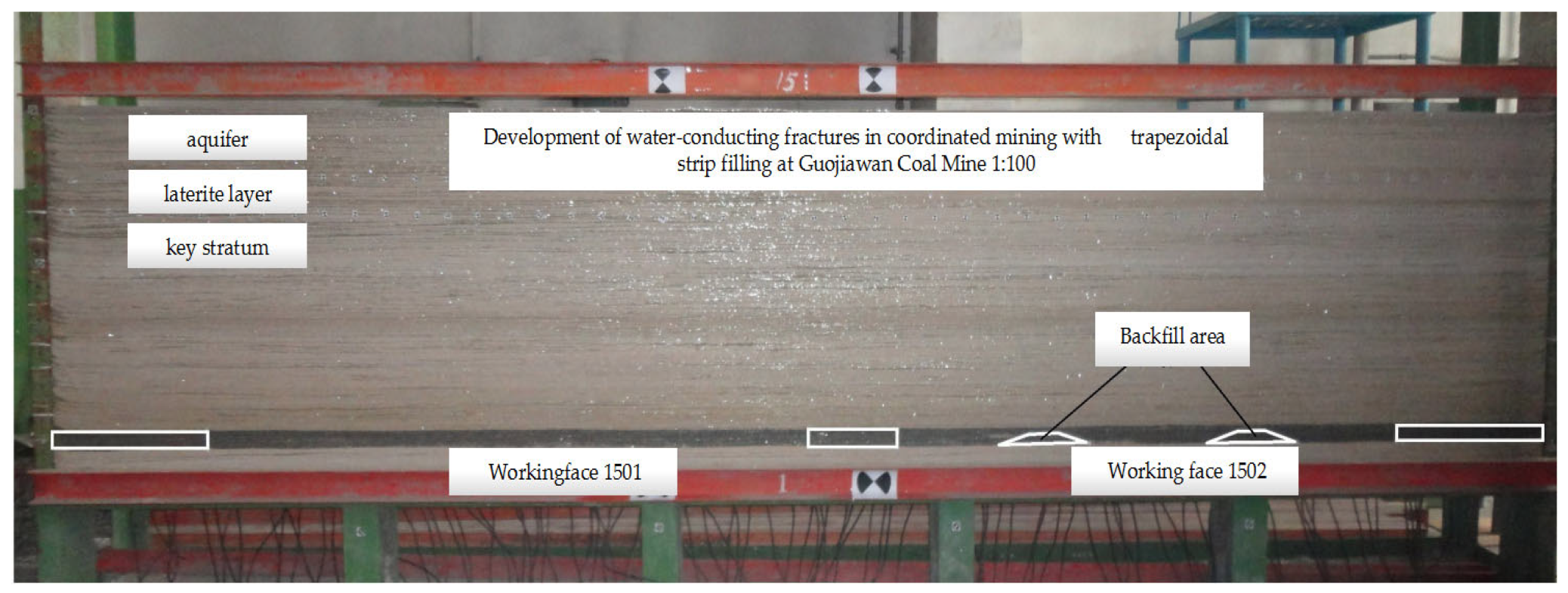
A plane-strain model frame measuring 5.0 m (length) × 1.8 m (height) × 0.2 m (thickness) was used in the experiment. Based on the stratigraphic columnar diagram, river sand served as the aggregate, while gypsum and calcium carbonate were the cementing agents. Simulated materials for each rock layer were placed and compacted in successive lifts. A systematic preliminary mixing ratio test ensured that the density, uniaxial compressive strength, and elastic modulus of each layer met the similarity requirements. The trapezoidal backfill body was reproduced with a purpose-designed low-strength cemented material to capture its load-bearing and deformation behavior accurately [25,26,27]. The model assumes an average mining depth of 112 m, a 1501 working face length of 300 m, and a 1502 working face length of 125 m. Table 3 lists the similarity mixing ratios, and Figure 3 presents the physical similarity simulation.
Table 3.
Material proportions of the simulation model.
Figure 3.
Photograph of the physical similarity simulation model.
4.2.3. Monitoring Scheme and Simulation Process
An integrated monitoring system [28] was developed to capture mechanical responses during physical simulation. It includes full-field deformation, local stress, and key-point displacement monitoring. The system components are: Digital image correlation for full-field deformation monitoring with ±0.01 mm accuracy, miniature earth-pressure sensors for local stress monitoring (range: 0–5 MPa, accuracy: 0.01 MPa), and high-density displacement markers for key-point displacement monitoring of the key stratum. Settlement curves were extracted from DIC data for bending deformation quantification. The camera has a resolution of 12 megapixels, with a spatial resolution of 0.1 mm per pixel.
The simulation compares two mining schemes: Scheme A (control, caving method) models the 1501 working face with continuous excavation at 5 cm per step. Scheme B (trapezoidal strip backfilling) models the 1502 working face with a cyclic “excavation–backfilling–stabilization” process. A 35 cm wide coal strip is excavated and backfilled with a similar material to form trapezoidal artificial support, simulating progressive artificial support to overlying rock.
4.3. Research Findings and Comprehensive Analysis
4.3.1. Overburden Failure Characteristics in Caving Mining (Scheme A)
The simulation results present the typical catastrophic characteristics of the caving mining method in shallow coal seams, which are consistent with the laws of on-site engineering disasters.
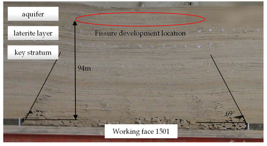
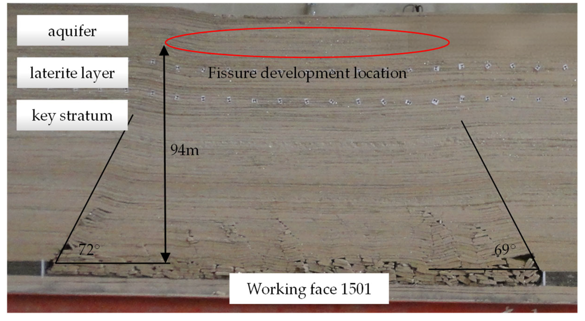
Disaster caused by fracture penetration: The overlying rock subsides in a stepwise fashion [28,29], behaving like a “masonry beam” and producing longitudinal shear fractures that propagate from the bottom upward. As the working face advances, the fracture zone continues to grow upward and ultimately forms a V-shaped penetrating fracture zone 94 m in height that reaches the surface. The maximum fracture angle is 72°, which directly penetrates the Salawusu Formation aquifer (Figure 4).
Figure 4.
Overburden evolution pattern and fissure development morphology at the end of Working face 1501 mining.
Instability and failure of the key stratum: Shear slip and fracturing [30,31] of the key stratum lead to a complete loss of its waterproofing function, which is the principal trigger of groundwater leakage.
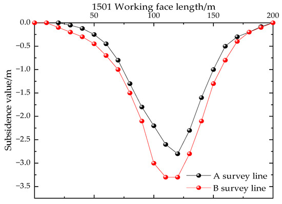
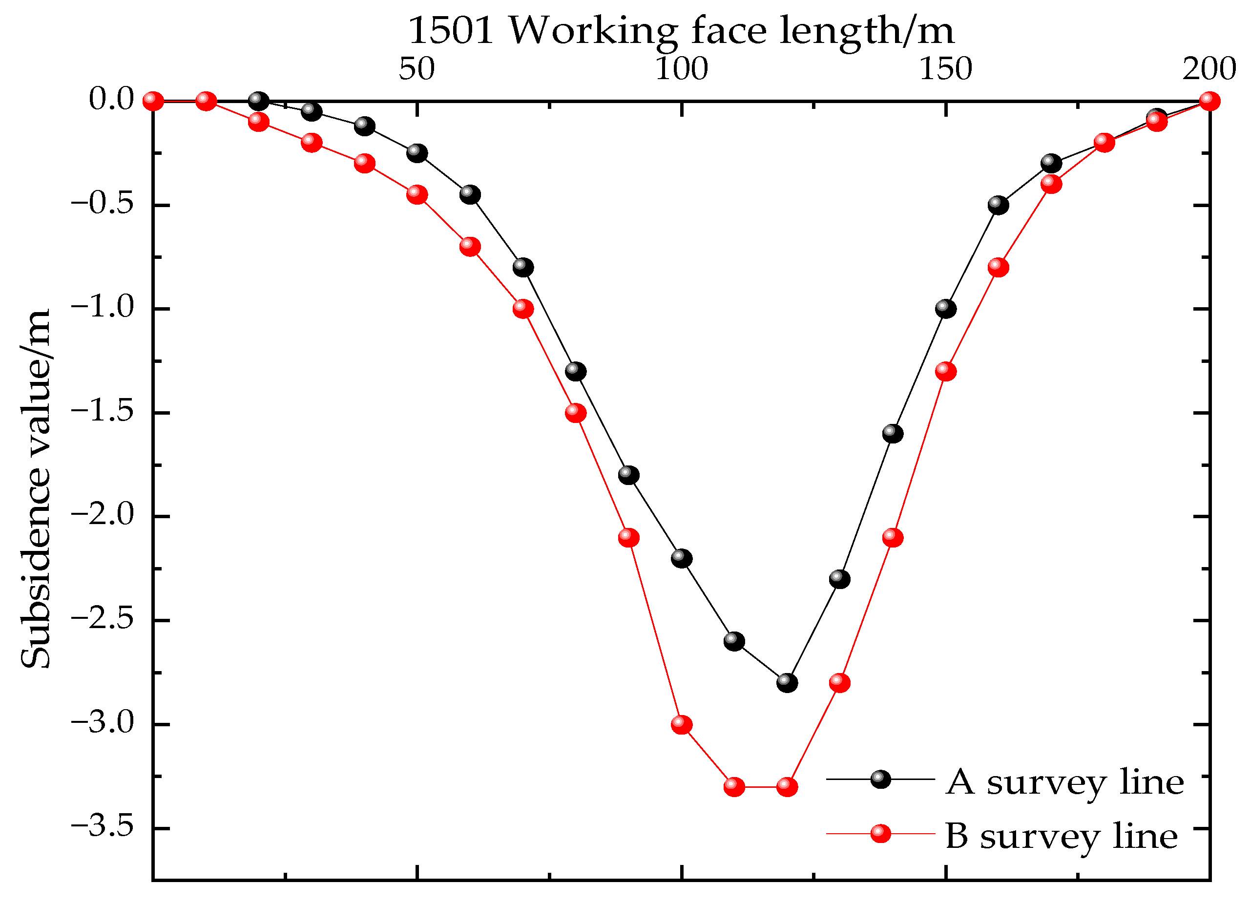
Rock movement and stress concentration: The coal pillar’s peak stress reaches 3.3 MPa (Figure 5). Consequently, the coal pillar bears the concentrated load from the overlying strata and the system becomes highly unstable. This instability can readily trigger cascading failures initiated by coal pillar collapse. As a result, a subsidence basin forms at the surface with a maximum depth of 3.3 m (Figure 6).
Figure 5.
Pressure distribution at the end of Working face 1501.
Figure 6.
Bending and subsidence curves of Working face 1501.
4.3.2. Overburden Control Effectiveness of Trapezoidal Strip Filling Mining (Scheme B)
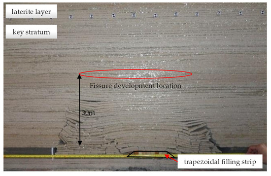
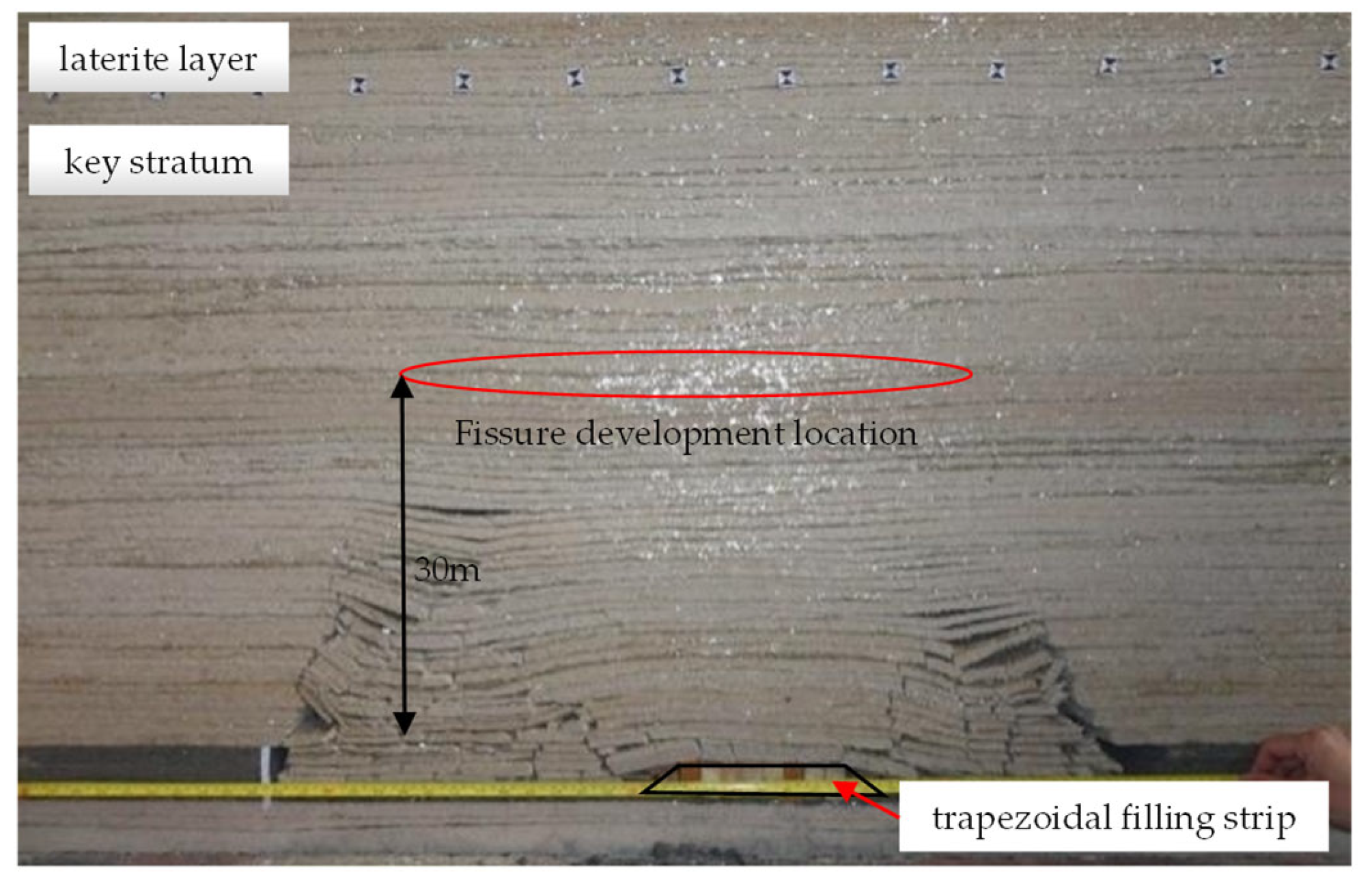
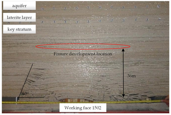
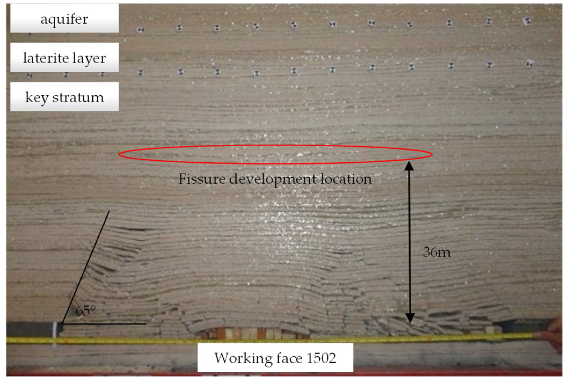
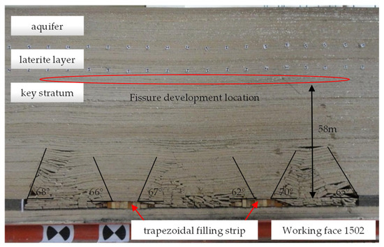
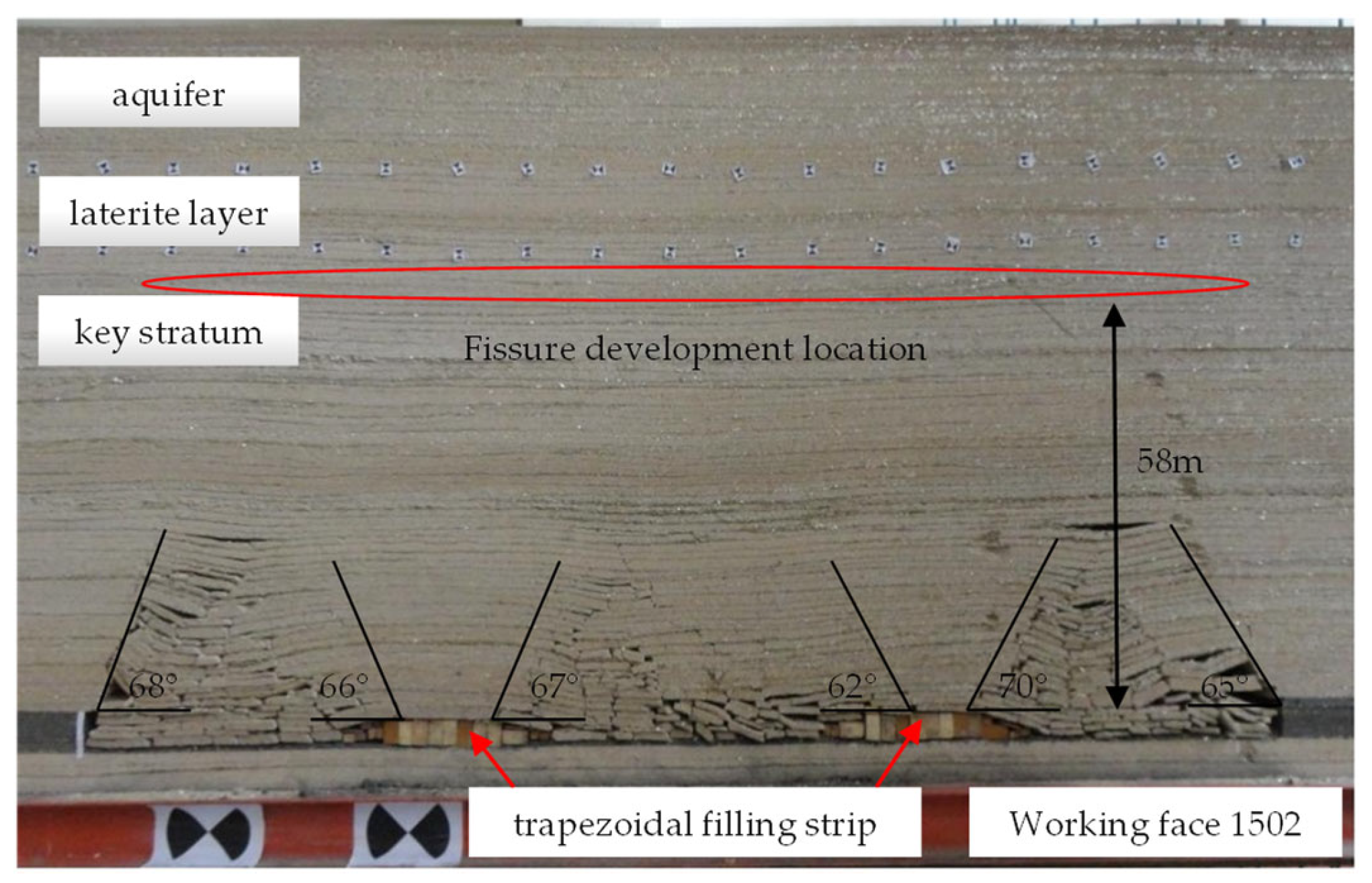
After implementing the trapezoidal filling scheme (Figure 7, Figure 8 and Figure 9), the failure mechanism of the overlying strata fundamentally changed, achieving the objectives of “crack control–layer protection–stable displacement”.
Figure 7.
Overburden evolution pattern and fissure development morphology after the first trapezoidal strip filling.
Figure 8.
Overburden evolution pattern and fissure development morphology after the second trapezoidal strip filling.
Figure 9.
Overburden evolution pattern and fissure development morphology at the end of trapezoidal strip filling mining.
Fracture development was restrained: The filled strips created continuous support, markedly shortening the effective span of the key stratum. When fractures propagated upward to 58 m, the filling body blocked further growth, producing multiple isolated, non-through V-shaped fractures. Consequently, no water-conducting channels connected to the aquifer formed, and the height of the water-conducting fracture zone decreased by 38.3%.
Coordinated deformation of the key stratum: Supported by the backfill body, the key stratum undergoes overall bending settlement without shear failure, which directly confirms the core theory in Section 3 that “the deflection decreases sharply by the fourth power with the reduction of the span”. When the span is reduced from 20 m to 12 m, the deflection decreases by 86.9%, thereby preserving the integrity of the key stratum.
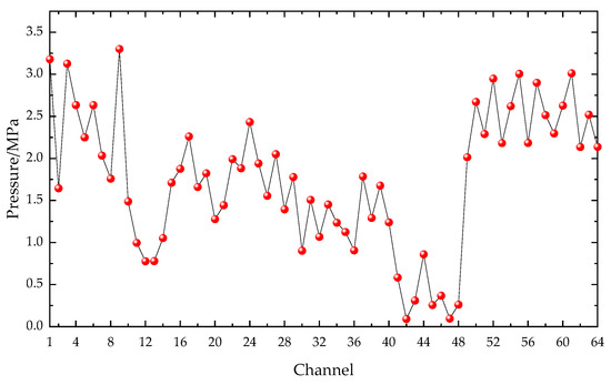
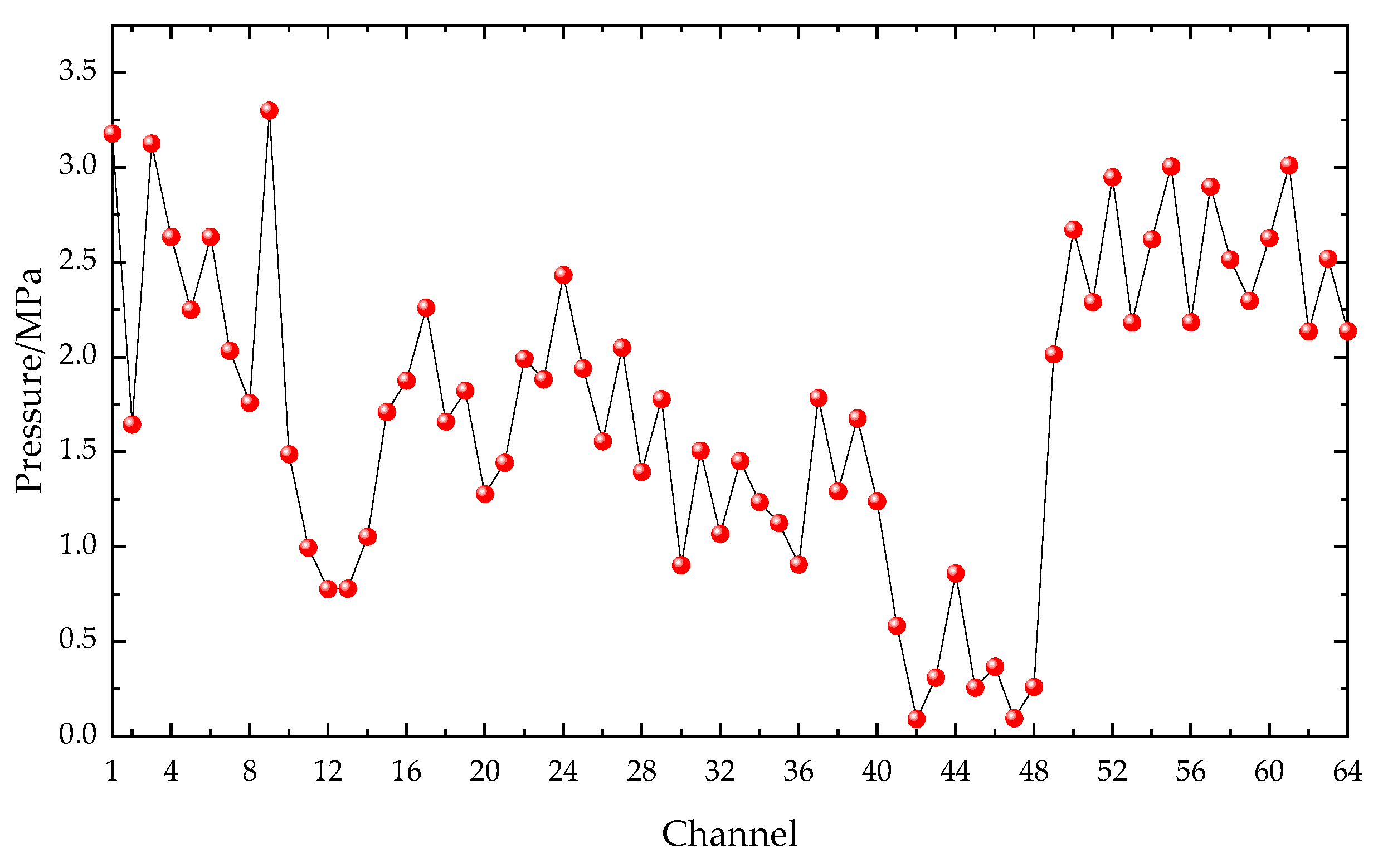
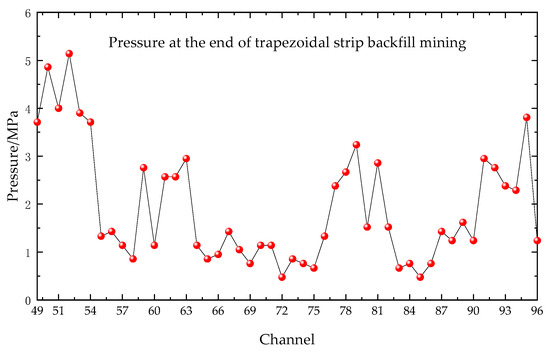
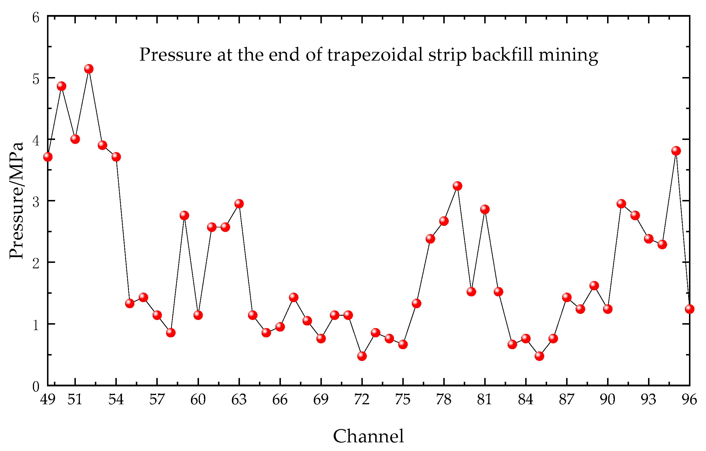
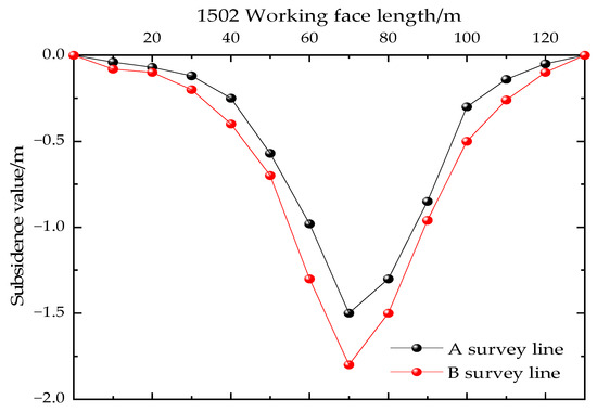
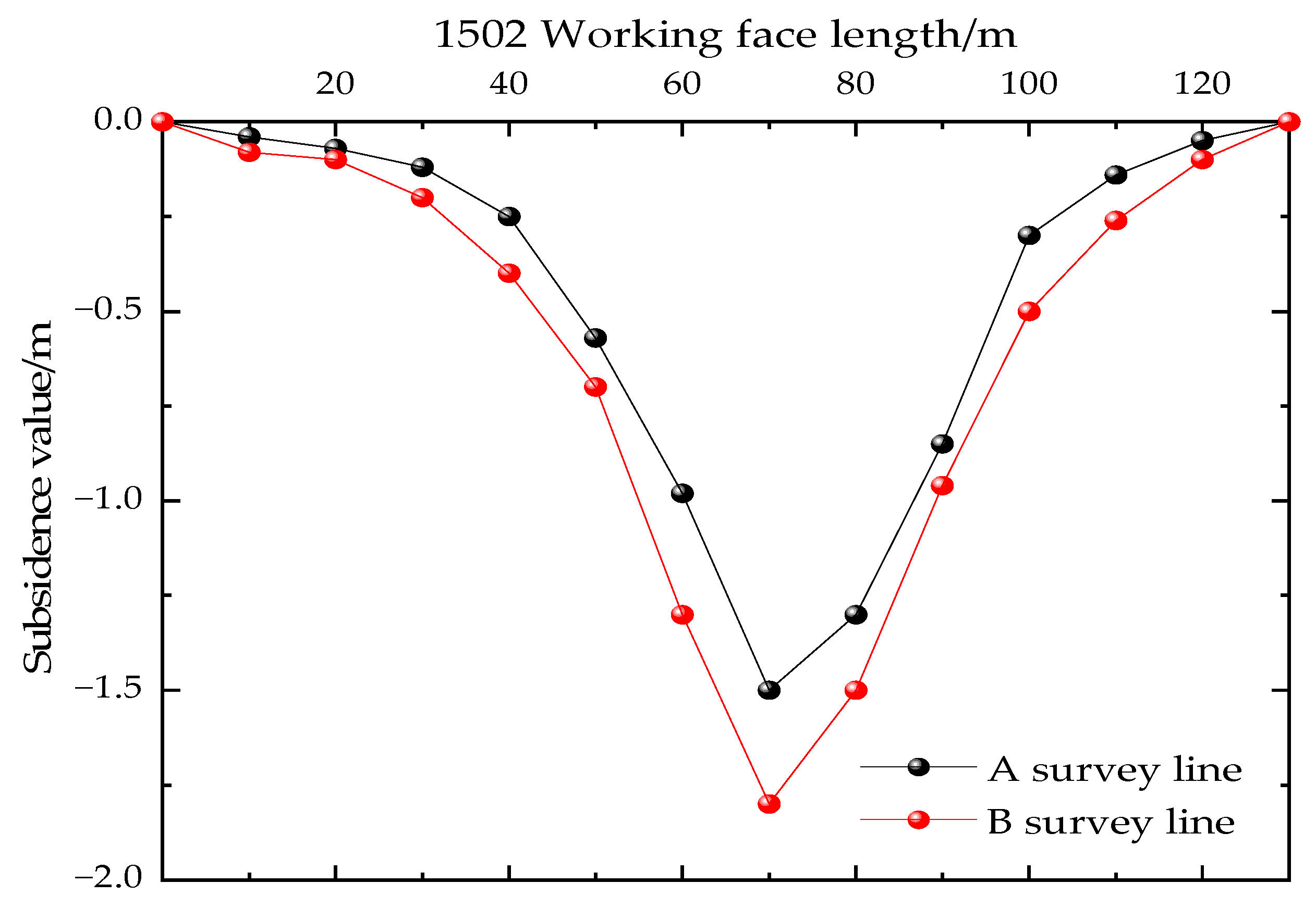
Load transfer and settlement control: Pressure measurements (Figure 10) indicate that the backfill attains a peak bearing capacity of 3.0 MPa, enabling load transfer to the “backfill–coal pillar” composite system [32,33]. The key stratum exhibits a gentle settlement curve [34] (Figure 11) with a maximum settlement of 1.8 m, which is 45.5% less than that observed for the caving method (the original value of 48% reflected a calculation error and has been corrected). The waterproofing function of the stratum remains intact.
Figure 10.
Pressure distribution at the end of backfill mining in Working face 1502.
Figure 11.
Bending and subsidence curves of Working face 1502.
5. Numerical-Simulation-Based Study on the Development Patterns of Water-Conducting Fracture Zones in Strip Filling Mining
5.1. Numerical Model Construction
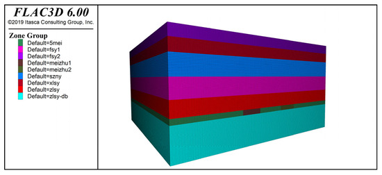
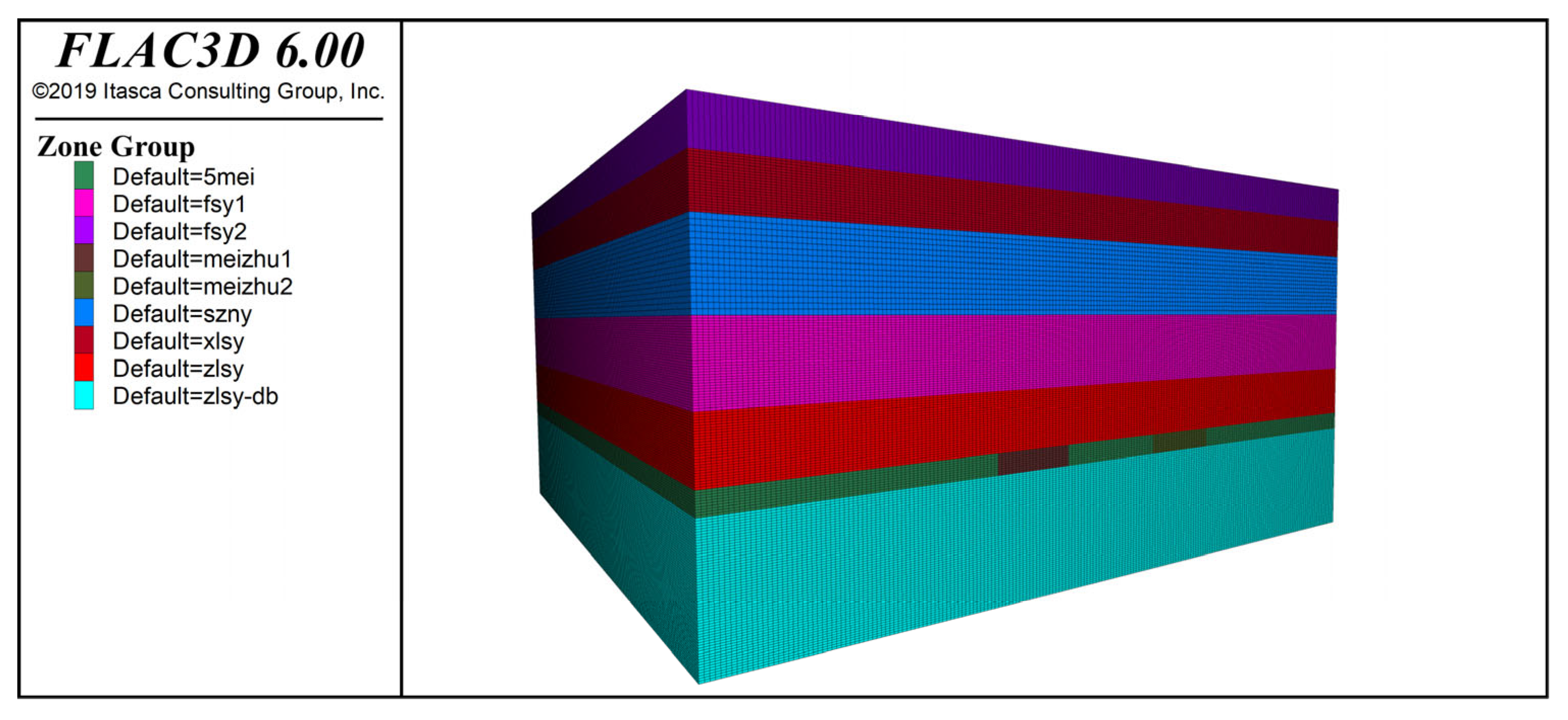
To investigate the control mechanisms of overburden failure during strip filling mining, this study employed FLAC3D 6.0 software to establish a three-dimensional numerical model based on the actual geological conditions of the 1501 and 1502 working faces at Guobao Coal Mine. This model enables comparative analysis of overburden responses induced by conventional caving methods versus trapezoidal strip filling mining.
The model dimensions were set as length × width × height = 300 m × 200 m × 110 m. Boundary conditions were defined as follows: Displacement constraints were applied to the model perimeter and base surface, while the top surface was set as a free boundary. The coal seam is buried in the middle-lower part of the model with a mining thickness of 4.6 m. The rock strata are divided into 11 mechanical units based on actual core logs, with lateral joints simulating weak bedding planes inserted between strata. Mining simulation employs a stepwise advancement method, advancing 10 m per step, completing a total of 40 mining stages. A 30 m wide coal pillar is retained at each end of the model as boundary protection. The 1501 working face simulated conventional roof caving mining with single-pass full-height extraction; the 1502 working face simulated trapezoidal stripping and backfilling mining. Rock physical and mechanical parameters are detailed in Table 1, and the established numerical model is shown in Figure 12.
Figure 12.
FLAC3D Numerical Model.
5.2. Comparative Analysis of Development Characteristics of Water-Conducting Fracture Zones
5.2.1. Failure Mode of Overburden: From Through Failure to Local Control
- (1)
- Traditional collapse method (1501 working face): The formation of a penetrating water channel
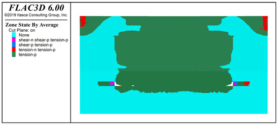
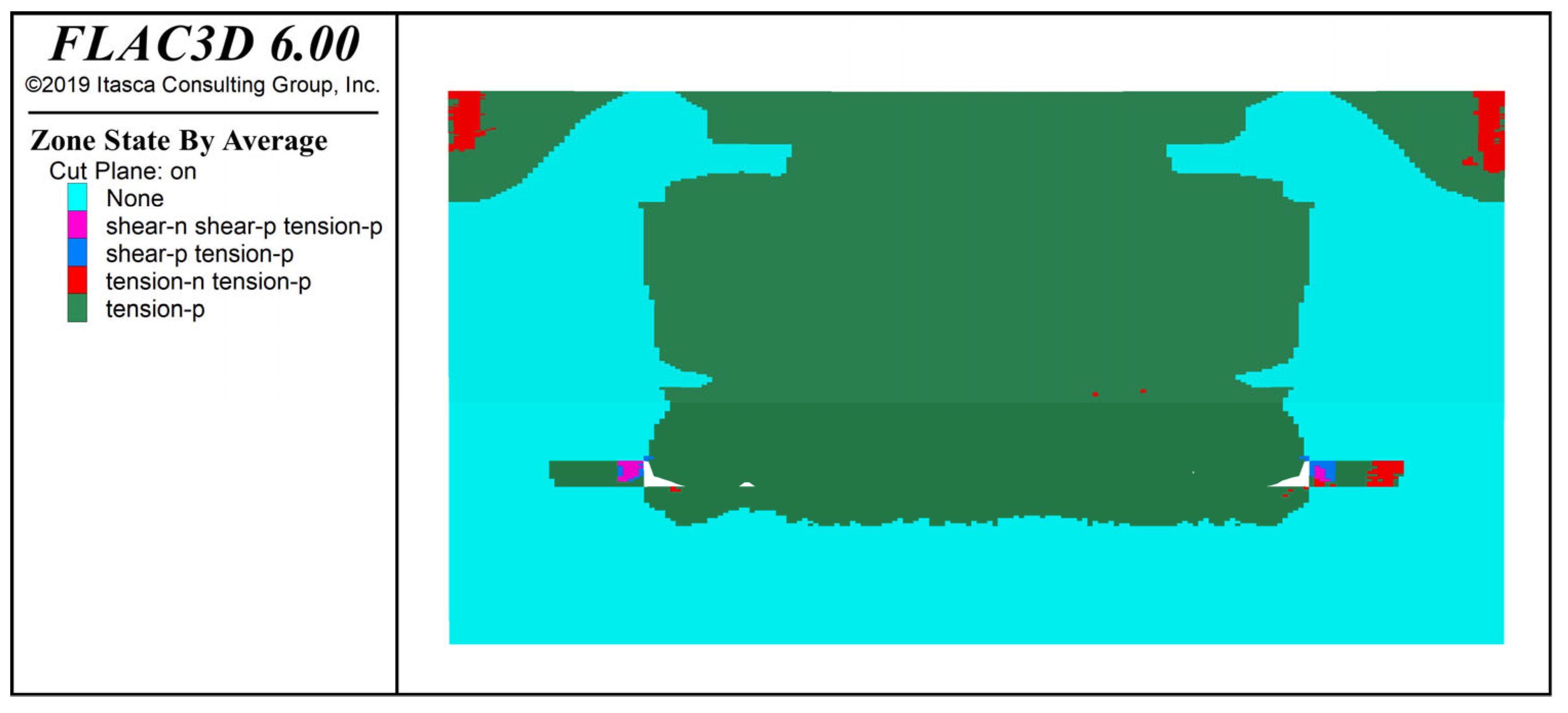
Simulation results indicate that, during coal mining operations, the plastic failure zone initiates at the coal face adjacent to the shear plate and baffle plate of the shearer, propagating upward and toward the center of the goaf. It ultimately forms a shear–plastic zone approximately 92 m above the goaf. This plastic zone completely penetrates the critical water-stop layer, indicating shear failure. The bottom-up failure pattern suggests leakage has occurred in the upper aquifer, consistent with observations from boreholes (Figure 13).
Figure 13.
Distribution Characteristics Map of Plastic Zones in the 1501 Working Face.
- (2)
- Trapezoidal strip filling method (1502 working face): Effective barrier of crack development
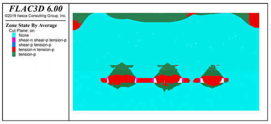
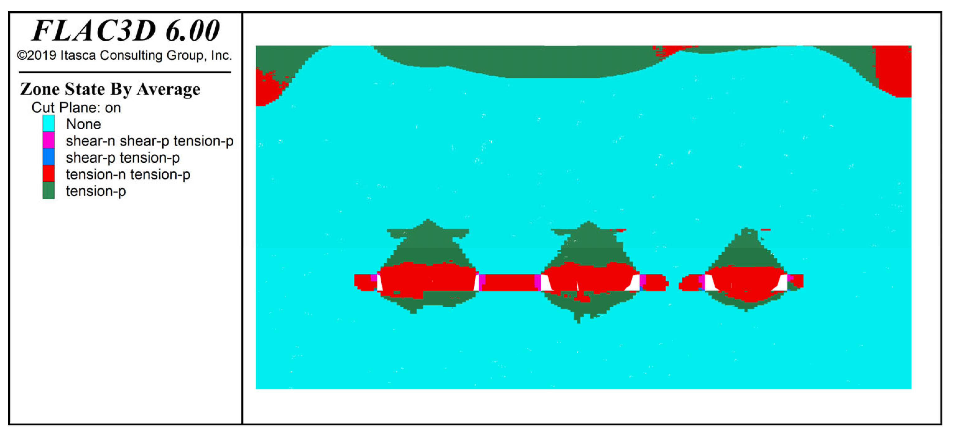
The trapezoidal fills alter the failure of the overburdened rock. The plastic zone is restricted to overburdened rock between fill bands. As the overburdened rock grows upwards to 54 m, it is contained by the support area formed by the upper fill and forms scattered, isolated, and disconnected “V”-shaped zones (Figure 14). Only small number of discontinuous plastic points are formed in the key aquifer, and mechanical state is mainly elastic or elastic–plastic. This explains why the filling body is responsible for reducing the effective span of the key aquifer to “breaking” range, regulating mechanical behavior from the “small-span safe bending” range, and thus restricting development height of the water-conducting fracture zone and the key layer.
Figure 14.
Distribution Characteristics Map of Plastic Zones in the 1502 Working Face.
5.2.2. Mining Stress Path: From Centralized Bearing to Coordinated Transfer
- (1)
- Stress concentration effect of traditional collapse method
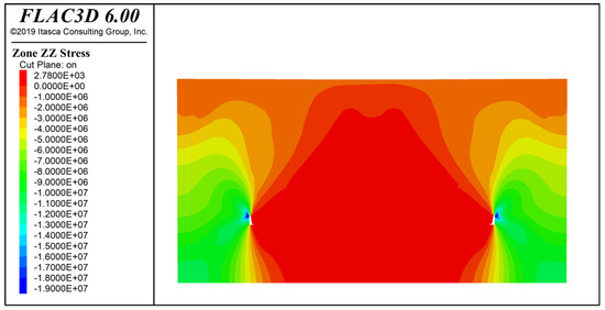
Mining stress is transferred to coal pillars and solid coal areas adjacent to the goaf, leading to a vertical stress concentration of up to 19 MPa at the edges of the coal pillars (Figure 15). This elevated stress causes the coal pillars to enter a state of plastic yield, resulting in a significant reduction in system stability. The overburden load is transmitted through a steep “stress arch,” with the arch foot exerting pressure on the key aquiclude. Consequently, the concentrated shear force emerges as the primary mechanical cause of failure in the key stratum.
Figure 15.
Vertical Stress Distribution Map for the 1501 Working Face.
- (2)
- Stress synergistic mechanism of trapezoidal strip filling method
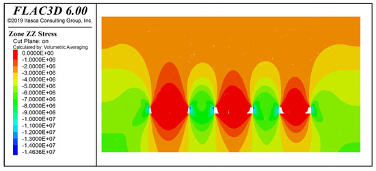
The trapezoidal filling body serves as the primary support system for load bearing. The stress cloud diagram indicates a high-stress zone located directly above the filling strip, with a peak vertical stress of 13 MPa in the backfill body (Figure 16). This observation suggests that the overlying load is effectively transferred to the fill–coal pillar composite structure. By providing continuous support through the filler, the extent of the pressure relief zone above the goaf diminishes, resulting in a gentler and more uniform stress arch shape. Consequently, the stress concentration on the coal pillar is alleviated, contributing to the overall stability of the mining system from a mechanical perspective.
Figure 16.
Vertical Stress Distribution Map for the 1502 Working Face.
5.3. Research Results and Analysis
This study, through a systematic analysis of FLAC3D numerical simulation results, elucidates the fundamental difference in overburden response between two mining methods. The traditional caving method follows a catastrophic evolution path: Coal seam extraction leads to rock unloading, causing stress concentration on the coal pillar and the formation of a high-stress arch. The surrounding rock of the coal wall and key water barrier experience shearing failure under intense shear stress. The failure area progressively expands, forming a water diversion channel connecting with the aquifer. Consequently, the load primarily shifts to the yielding coal pillar, resulting in significant surface subsidence. In contrast, the trapezoidal strip filling approach demonstrates an effective control mechanism: The filling body offers active support, reducing the effective span of the key waterproofing layer. According to thin-plate theory, the relationship between bending moment and shear force of the key layer decreases significantly to the fourth power. This leads to a coordinated bending deformation of the overlying rock, confining plastic failure locally without penetration. The “filling body–coal pillar” composite support system uniformly bears the load, effectively managing surface subsidence.
Numerical simulation confirms the theory of the work by showing that shortening the effective span of key strata by fillings is critical to control overburden deformation and failure. This comparison shows how traditional methods using passive coal pillar bearing can lead to disasters, while optimizing an artificial support system improves mechanical boundary allowing stress dispersion, damage suppression, and deformation coordination.
6. Field Verification of Project: Observation of Underground Inverted Hole Segmented Water Injection
To directly measure the in situ development height of the water-conducting fracture zone (WCFZ) and to validate the physical simulation results, this study applied the underground upward-borehole segmented water injection method following the “Specification for hydrogeological exploration of coalfields” (GB/T 12719-2021 [35]) [36,37,38]. We performed comparative in situ observations on adjacent working faces in Guojiawan Coal Mine: The 1501 face, mined by the traditional caving method, and the 1502 face, mined by the trapezoidal strip filling method.
6.1. Field Measurement Plan
6.1.1. Project Background and Comparative Design
To isolate the effect of individual variables in the mining process, we selected adjacent working faces 1501 and 1502 with highly consistent geological conditions for field measurement. The coal seams in both faces have essentially identical burial depths (108–115 m), thicknesses (4.5–4.7 m), and dip angles (0.8–1.2°), which ensures the observations are reliable and comparable. The field measurement had three primary objectives: (1) To quantify the actual development heights of the water-conducting fracture zone (WCFZ) under two mining methods; (2) to validate the accuracy of the physical similarity simulation experiment for predicting fracture zone heights; and (3) to quantitatively assess, under field conditions, the control effectiveness of the backfilling method that relies on the “span reduction” mechanism [39].
6.1.2. Observation Principles and Methods
This method is based on the marked contrast in permeability between intact and fractured rock. Intact rock has low permeability, so segmented constant-pressure water injection produces only small, stable leakage. When a borehole intersects a water-conducting fracture zone, the developed fracture network sharply increases permeability and causes a sudden rise in leakage. Therefore, upwardly inclined boreholes with an elevation angle of 70–90° are drilled in the return airway, segmented constant-pressure water injection tests are performed, and a plot of water leakage versus borehole depth is produced. The clear inflection point on this curve reliably indicates the upper boundary of the water-conducting fracture zone [40].
6.1.3. Borehole Arrangement and Test Process
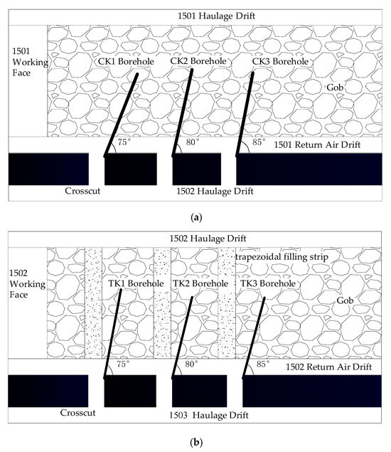
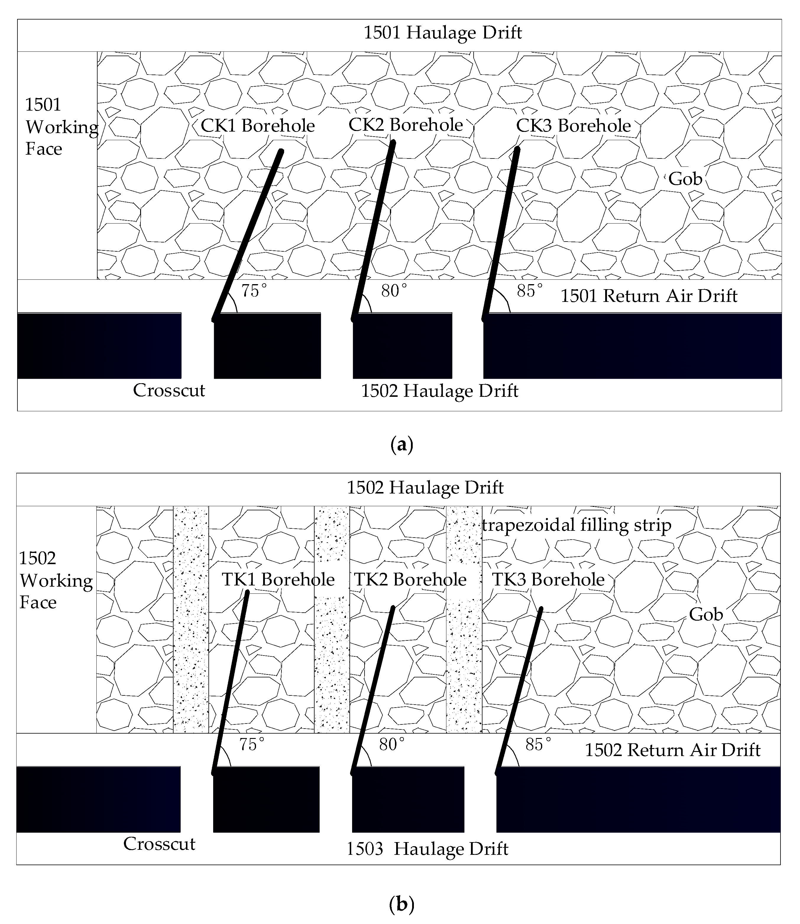
Each return-airway connecting roadway contained three observation holes per working face, for a total of six holes. The holes were spaced at least 50 m apart to ensure independent observations (for the specific layout, see Figure 17a,b, and the parameters are shown in Table 4). An automated monitoring system—comprising a high-pressure grouting pump, a high-precision flowmeter, and a pressure sensor—was used for the test. Field operations adhered strictly to the relevant specifications. Testing proceeded in 2 m sections. Each section was injected at a constant water pressure of 0.2–1.0 MPa. Once the flow rate stabilized, the standard water leakage for that section was recorded, providing systematic data on permeability changes across the full borehole depth.
Figure 17.
Schematic diagram of the borehole layout plan. (a) 1501 Schematic diagram of the borehole layout plan. (b) 1502 Schematic diagram of the borehole layout plan.
Table 4.
Geometric and spatial parameters of the boreholes.
6.2. Results and Analysis
6.2.1. Caving Method Working Face (1501)
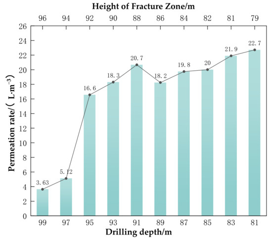
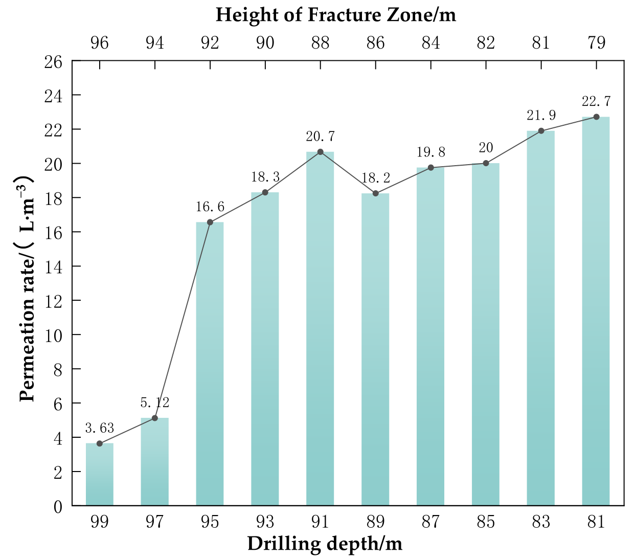
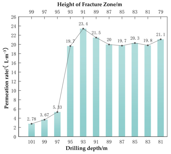
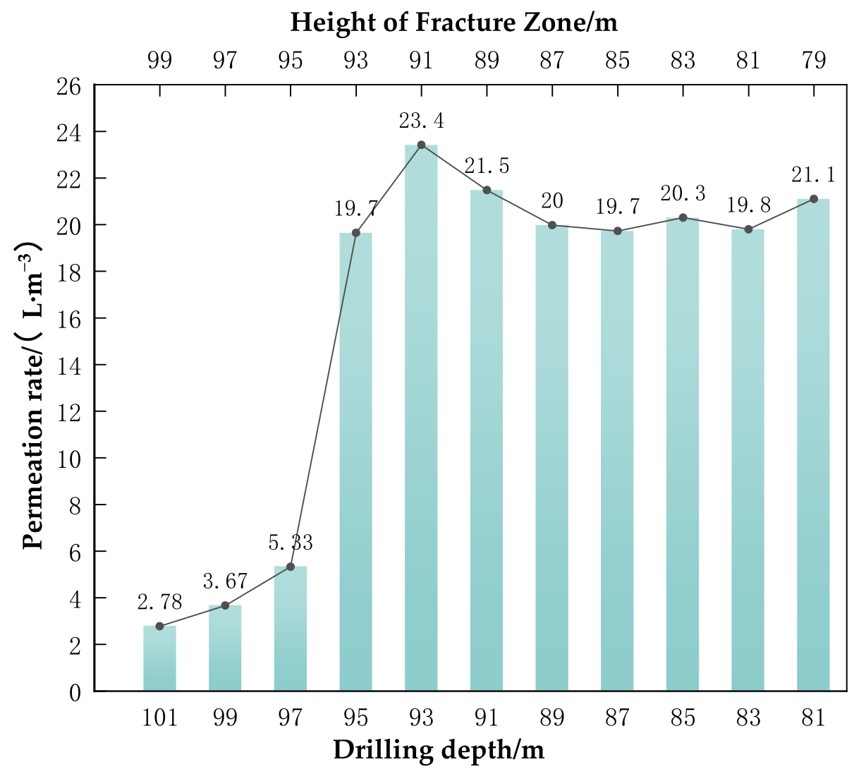
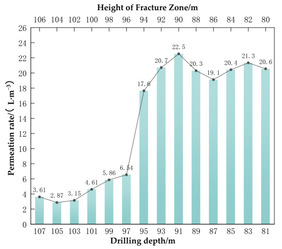
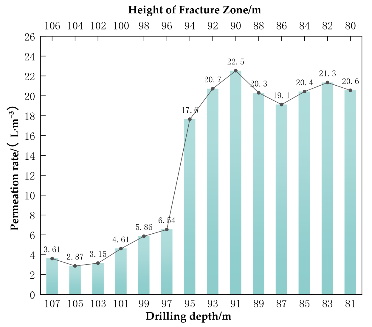
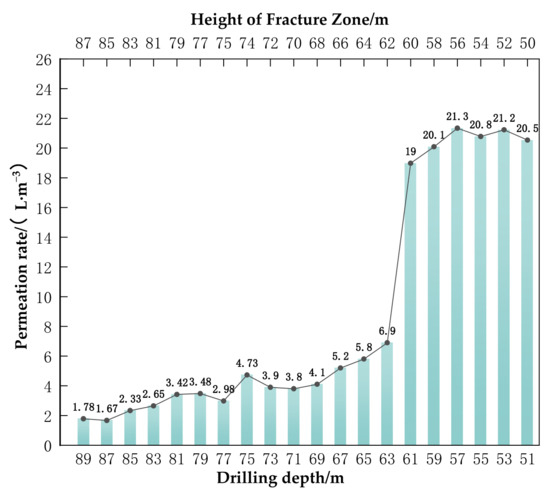
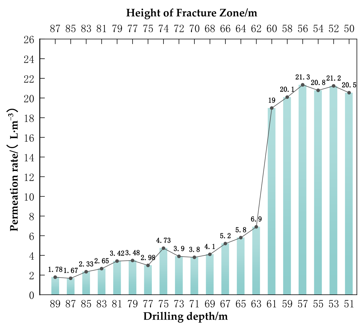
Using data from the representative observation borehole CK3, the overburden damage caused by conventional caving mining is both severe and widespread (Figure 18, Figure 19 and Figure 20 and Table 5).
Figure 18.
CK1 Gradient Map of Permeability Variation in Drilled Injection Wells.
Figure 19.
CK2 Gradient Map of Permeability Variation in Drilled Injection Wells.
Figure 20.
CK3 Gradient Map of Permeability Variation in Drilled Injection Wells.
Table 5.
Summary of field-measured leakage data for borehole injection tests in Panel 1501.
When borehole depth lies between 107 m and 97 m, the water injection seepage rate [41] ranges from 3.61 to 5.54 L/min, with a mean of 4.58 L/min, indicating relatively low permeability. Below 97 m, the seepage rate abruptly rises from 5.54 L/min to 21.64 L/min. From 97 m to 80 m, the rate increases markedly. In the vertical interval from 94.05 m to about 80.19 m, the leakage rate Q remains high at 17.64–22.53 L/(min·m) and fluctuates strongly, indicating that fractures in this rock interval are both highly developed and well connected, forming an efficient water-conducting channel. Above a vertical depth of 92 m the leakage rate declines slowly and shows no sharp transitions. Combining data from three boreholes, the maximum development height of the water-conducting fracture zone in the 1501 working face is determined to be 93 m. This height well exceeds the key stratum, causing complete failure of the key water-resisting layer and allowing the fracture zone to extend upward near the top of the bedrock, which poses a direct threat to the shallow aquifer.
6.2.2. Trapezoidal Strip Filling Working Face (1502)
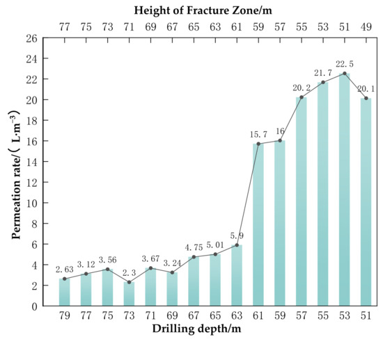
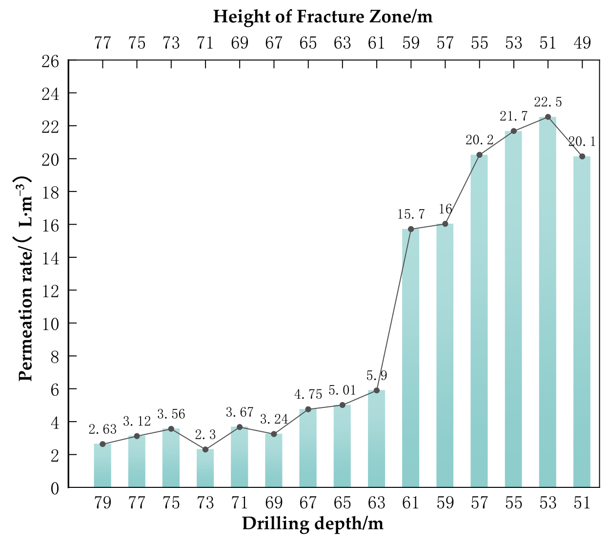
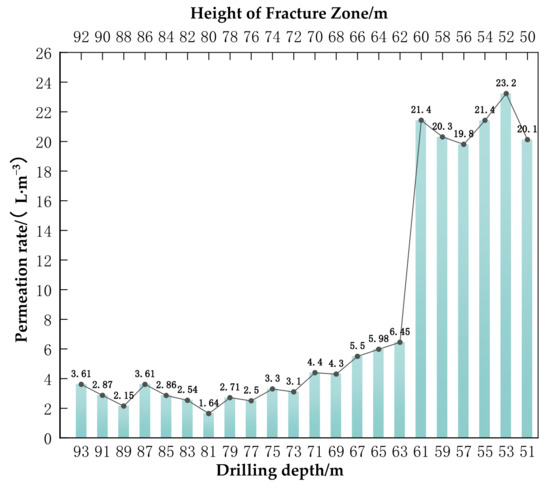
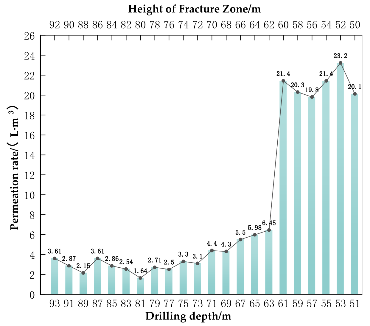
Data from observation hole TK1 indicate that trapezoidal strip filling mining produces a controlled damage pattern that differs markedly from the collapse method (Figure 21, Figure 22 and Figure 23 and Table 6). Between depths of 79 m and 63 m, water injection permeability ranges from 2.63 to 5.9 L/min, with an average of 4.27 L/min, indicating low permeability. Below 61 m, permeability increases abruptly from 5.9 L/min to 15.7 L/min; this pronounced rise occurs primarily between 61 m and 50 m. In the interval 59.17–49.47 m, the Q value remains high, between 15.71 and 22.54 L/(min·m), identifying a conductive fracture zone. A critical transition is observed at 59–60 m, where the Q value falls sharply from approximately 15.7 L/(min·m) to 5.9 L/(min·m), Above this depth, the Q value remains very low, at approximately 5 L/(min·m). Combining data from the three drill holes indicates that the water-conducting fissure zone in the 1502 working face is confined to a maximum height of 59 m, and its upper boundary is unusually well defined.
Figure 21.
TK1 Gradient Map of Permeability Variation in Drilled Injection Wells.
Figure 22.
TK2 Gradient Map of Permeability Variation in Drilled Injection Wells.
Figure 23.
TK3 Gradient Map of Permeability Variation in Drilled Injection Wells.
Table 6.
Summary of field-measured leakage data for borehole injection tests in Panel 1502.
6.2.3. Comprehensive Comparison and Verification
Aggregating data from all boreholes (Table 5 and Table 6) shows that trapezoidal strip backfilling reduced the water-conducting fracture zone (WCFZ) height from 93 m under the caving method to 59 m, a 36.6% decrease. With the backfill in place, the key aquiclude remained intact above the WCFZ top boundary and continued to function effectively as an aquiclude. The measured WCFZ height (59 m) closely matched the 58 m predicted by the physical similarity simulation, confirming both the simulation’s accuracy and the effectiveness of the span reduction mechanism.
Based on data from each borehole, a comparative analysis was conducted to statistically validate field water injection data from conventional caving mining (LC) and trapezoidal strip block mining (TSB) workfaces. All valid permeability data within the water-conducting fracture zones of both working faces were included (LC: n = 27; TSB: n = 18). Since the data did not satisfy the prerequisites for parametric tests (normality p < 0.05, homogeneity of variance p < 0.05), the non-parametric Kruskal–Wallis H test was employed.
Calculations revealed a highly significant statistical difference in fracture zone permeability between the two methods (H = 11.24, p < 0.001). The median permeability (20.43 L/min) and mean rank (28.61) of the traditional caving face were significantly higher than those of the backfilling face (20.09 L/min, mean rank 15.50). The extremely significant p < 0.001 result probabilistically confirms that the observed reduction in permeability is not coincidental but a systematic effect of the trapezoidal filling process. This validates the fundamental effectiveness of this technology in controlling the development of water-conducting fracture zones and achieving water-conserving mining.
7. Discussion
This study innovatively reveals the dual-control mechanism of “span reduction” and “stiffness coordination” in the partial backfilling method with trapezoidal strips. By optimizing the spatial layout of the backfill body, this method actively adjusts the mechanical boundary conditions of the key stratum, transforming it from the original “simply supported free” state to a “multispan simply supported” system. Based on the thin-plate theory, the maximum deflection of the key stratum is in a quartic relationship with its effective span (w∝a4). Therefore, a significant reduction in the effective span can lead to an exponential decrease in the bending stress of the key stratum, thus changing the failure mode of the overlying strata from severe “breaking and conduction” to gentle “bending and settlement”. In addition, by designing the elastic modulus of the backfill body to increase gradually from bottom to top, the deformation coordination between the backfill body and the surrounding rock is further enhanced. The simulation results show that this gradient stiffness design allows the backfill body to bear approximately 35–42% of the overlying strata load, effectively alleviating the stress concentration of the key stratum.
In terms of technical economy and applicability, this method has significant advantages over traditional full backfilling (high cost) and narrow strip mining (low recovery rate). It achieves a better balance between the control of the height of the water-conducting fractured zone, coal recovery rate (increased to 82%), and backfilling cost per ton of coal (reduced by approximately 40%). This method is particularly suitable for the mining conditions of nearly horizontal coal seams with shallow burial depth (burial depth < 100 m) and thin bedrock. In engineering applications, parameters such as strip spacing (25–40 m) and backfill stiffness (1.5–3.0 GPa) can be adjusted to flexibly meet different geological and engineering requirements.
In summary, the main innovative contributions of this study include the following three aspects:
- (1)
- Theoretical innovation: For the first time, the relationship between the deflection of the key stratum and the fourth power of the span was transformed into a backfill design criterion, achieving a leap from empirical design to mechanical quantitative design.
- (2)
- Method innovation: A spatial configuration criterion for the gradient stiffness of trapezoidal backfill bodies was proposed, effectively addressing the coordination issue at the backfill–surrounding rock interface.
- (3)
- Innovation in the verification system: A closed-loop verification system integrating “theoretical model–physical simulation–numerical simulation–on-site measurement” is established to enhance the reliability of the conclusions. Compared with existing technologies, the trapezoidal strip local backfilling method offers distinct comprehensive advantages in both control effectiveness and economic efficiency. This method effectively prevents the formation of water-conducting fracture zones that penetrate aquifers—a common issue with traditional full-caving mining—thereby avoiding irreversible water level decline and achieving proactive protection of aquifer structures. In ecologically fragile regions, this technology provides a scientifically feasible, engineering-effective, and cost-reasonable solution for green coal mining.
8. Conclusions
To address the technical challenges faced in water-preserving mining of shallow coal seams, this study proposes a trapezoidal strip filling method based on the “span reduction effect”. Through systematic research, the following core conclusions are mainly drawn:
- (1)
- For the first time, the quartic control relationship between the maximum deflection of the key stratum and its effective span was theoretically clarified.
(w ∝ a4). Calculations show that reducing the effective span by 40% decreases the deflection of the key stratum by 87%. This mechanical relationship therefore provides the theoretical basis for transforming the overlying strata’s failure mode from “fracture conduction” to “bending settlement”.
- (2)
- Method: Collaborative control is achieved through two mechanisms: Span reduction and stiffness synergy. The backfill provides elastic support to the key stratum and concurrently bears 35–42% of the overburden load. As a result, it significantly suppresses overall overburden deformation and the development of cracks.
- (3)
- Physical similarity experiments, numerical simulation studies, and field measurements of underground upward hole water injection corroborate one another and jointly demonstrate the method’s engineering effectiveness. At a filling rate of 65%, trapezoidal strip filling reduced the height of the water-conducting fracture zone from 93 m in conventional caving mining to an average measured value of 59 m, a 36.6% decrease, thereby effectively protecting the key aquifer.
Based on the above research findings, this study developed a standardized technical process covering parameter identification of key layers to optimal design of backfill parameters. This solution has a clear mechanism, remarkable control effects, and is economically viable, offering a promising technical option for the green and safe extraction of shallow-buried coal seams in ecologically fragile areas.
Author Contributions
Conceptualization, H.C. and X.Y.; methodology, H.C.; software (FLAC3D 6.0), Q.C.; validation, H.C., C.M. and Q.C.; formal analysis, H.C.; investigation, H.C.; resources, C.M.; data curation, H.C.; writing—original draft preparation, H.C.; writing—review and editing, H.C.; visualization, C.M.; supervision, X.Y.; project administration, H.C.; funding acquisition, H.C. All authors have read and agreed to the published version of the manuscript.
Funding
This project was financially supported by Key Laboratory of Mine Geological Hazards Mechanism and Control, Ministry of Natural Resources (SKF2024-06), the General Special Scientific Research Project of the Shaanxi Provincial Department of Education (23JK0378), and the Key Laboratory of Intelligent Prevention and Control for Coal Mine Disasters, Shaanxi Provincial Institutions of Higher Education, Research and Innovation Team on Mechanisms and Prevention of Dynamic Coal-Rock Disasters in Deep Mines (2024KYTD01), Innovative Team for Geological Assurance and Ecological Restoration in Green Coal Mining (2024KYTD03). This research was supported by the Shaanxi Provincial Education Department's Local Service Special Project (Project No.: 23JC024).
Institutional Review Board Statement
Not applicable.
Informed Consent Statement
Not applicable.
Data Availability Statement
The datasets generated and analyzed during the current study are available from the corresponding author upon reasonable request. These include raw experimental data, geomechanical simulation parameters, and field monitoring records. Due to the large file sizes and proprietary nature of some physical similarity simulation models, complete datasets are not publicly deposited but will be shared under a Material Transfer Agreement to ensure proper attribution and data security.
Acknowledgments
We thank the aforementioned foundation of for its support of this study. We thank the academic editors and anonymous reviewers for their kind suggestions and valuable comments.
Conflicts of Interest
The authors declare no conflicts of interest.
Abbreviations
The following abbreviations are used in this manuscript:
| WCFZ | Water-conducting fracture zone |
References
- Chen, W.; Li, W.; Yang, Z.; Wang, Q. Analysis of Mining-Induced Variation of the Water Table and Potential Benefits for Ecological Vegetation: A Case Study of Jinjitan Coal Mine in Yushenfu Mining Area, China. Hydrogeol. J. 2021, 29, 1629–1645. [Google Scholar] [CrossRef] [Scilit]
- Zeng, Y.; Pang, Z.; Wu, Q.; Hua, Z.; Lv, Y.; Wang, L.; Zhang, Y.; Du, X.; Liu, S. Study of Water-Controlled and Environmentally Friendly Coal Mining Models in an Ecologically Fragile Area of Northwest China. Mine Water Environ. 2022, 41, 802–816. [Google Scholar] [CrossRef] [Scilit]
- Xu, L.; Yu, F.; Tan, Y.; Zhang, C.; Zhou, K. The Evolution of Fractures in Deep, Weakly Cemented Overlying Strata and the Characteristics of Severe and Mild Fracture Zones. Geomech. Geophys. Geo-Energy Geo-Resour. 2024, 10, 94. [Google Scholar] [CrossRef] [Scilit]
- Guan, Y.; Guo, Q.; Pu, R.; Gao, X.; Chen, S.; Ji, T. Distribution of Upper Paleozoic Coal Seams in the Southeastern Ordos Basin. Energies 2022, 15, 5110. [Google Scholar] [CrossRef] [Scilit]
- Jianwen, W.; Xiurong, S.; Hongke, W.; Xueli, X.; Ruofei, C. Application of Integrated Seismic Prospecting in Northern Shaanxi Coalfields Gob Area Detection. Coal Geol. China 2010, 22, 48–54. Available online: http://en.cnki.com.cn/Article_en/CJFDTOTAL-ZGMT201009014.htm (accessed on 21 January 2026).
- Liu, Y.; Yang, T.; Deng, W.; Liu, H.; Gao, Y.; Ma, K.; Zhao, Y.; Sun, D. Characteristics of Overburden Damage and Rainfall-Induced Disaster Mechanisms in Shallowly Buried Coal Seam Mining: A Case Study in a Gully Region. Sustainability 2024, 16, 7538. [Google Scholar] [CrossRef] [Scilit]
- Wang, C.; Zhang, B.; Lu, Y.; Liao, C.; Lu, W. Failure Law of Floor during Strip Mining Backfill with Paste-Tailings over Confined Aquifer: A Case Study in China Mine. Case Stud. Constr. Mater. 2024, 20, e02806. [Google Scholar] [CrossRef] [Scilit]
- Du, Z.; Chen, D.; Li, X.; Jian, Y.; Zhang, W.; Zhang, D.; Tian, Y. Study on the Partial Paste Backfill Mining Method in a Fully Mechanized Top-Coal Caving Face: Case Study from a Coal Mine, China. Sustainability 2024, 16, 4393. [Google Scholar] [CrossRef] [Scilit]
- Bagde, M.N. Ore and Backfill Dilution in Underground Hard Rock Mining. J. Min. Sci. 2021, 57, 995–1005. [Google Scholar] [CrossRef] [Scilit]
- Roy, R.; Chakraborty, S.; Bisai, R.; Pal, S.K.; Mishra, S. Gravity Blind Backfilling of Abandoned Underground Mine Voids Using Suitable Mix Proportion of Fill Materials and Method of Filling. Geotech. Geol. Eng. Int. J. 2023, 41, 1801–1819. [Google Scholar] [CrossRef] [Scilit]
- Zhang, W.; Zhang, C.-W.; Guo, W.-Y.; Zhang, B.-L.; Liu, W.-R. Research on fracture characteristics and support mechanism of shallow buried double-soft composite roof. J. Cent. South Univ. 2025, 32, 1838–1854. [Google Scholar] [CrossRef] [Scilit]
- Jiang, N.; Wang, C.; Pan, H.; Yin, D.; Ma, J. Modeling Study on the Influence of the Strip Filling Mining Sequence on Mining-induced Failure. Energy Sci. Eng. 2020, 8, 2239–2255. [Google Scholar] [CrossRef] [Scilit]
- GB/T 50266-2013; Standard for Test Methods of Engineering Rock Mass. China Planning Press: Beijing, China, 2013.
- Chen, W.; Li, W.; He, J.; Qiao, W.; Wang, Q.; Yang, Y. Impact of Mining-Induced Bed Separation Spaces on a Cretaceous Aquifer: A Case Study of the Yingpanhao Coal Mine, Ordos Basin, China. Hydrogeol. J. 2022, 30, 691–706. [Google Scholar] [CrossRef] [Scilit]
- Lu, J.J.; Ren, G.F.; Zhen, Y. Study on Roof Breaking Characteristics of Gently InclinedStope in Multilayer Mine Based on Thin Plate Theory, China. J. Wuhan Univ. Technol. 2025, 47, 57–64. [Google Scholar] [CrossRef]
- Li, J.K.; Wang, Z.Q.; Li, Q.H. Chain instability mechanism and evaluation method of coal pillars-roof system in room and pillar mining goaf, China. J. Min. Strat. Control. Eng. 2025, 7, 043031. [Google Scholar] [CrossRef]
- Jahanpour, A.; Ahmadvand-Shahverdi, F. In-Plane Stiffness of Imperfect Thin Rectangular Plates Subjected to Biaxial Loads in Elastic Post-Buckling Region. Arch. Appl. Mech. 2021, 91, 2973–2989. [Google Scholar] [CrossRef] [Scilit]
- Fedoseyev, V.N.; Yagnyatinskiy, D.A. Deflection of a Thin Rectangular Plate with Free Edges under Concentrated Loads. Mech. Solids 2019, 54, 750–755. [Google Scholar] [CrossRef] [Scilit]
- Liu, H.; Deng, X.; Zheng, T.; Jia, N.; Zheng, Q.; Tian, X.; de Wit, B. Multi-Objective Ratio Optimization of Alkali-Activated Cemented Paste Backfill Mixtures Using the Sobol and Non-Dominated Sorting. Min. Metall. Explor. 2025, 1–21. [Google Scholar] [CrossRef] [Scilit]
- Fu, C.; Wang, C.; Zhang, F.; Chai, H.; Zhao, L.; Guan, X.; Zhu, J.; Zhang, H. Design and Properties of Paste Backfill Materials Based on Close Packing Theory. Min. Metall. Explor. 2025, 42, 2187–2203. [Google Scholar] [CrossRef] [Scilit]
- Frühwirt, T.; Pötschke, D.; Konietzky, H. Simulation of Direct Shear Tests Using a Forces on Fracture Surfaces (FFS) Approach. Environ. Earth Sci. 2021, 80, 312. [Google Scholar] [CrossRef] [Scilit]
- Liu, P.; Gao, L.; Zhang, P.; Wu, G.; Wang, Y.; Liu, P.; Kang, X.; Ma, Z.; Kong, D.; Han, S. Physical Similarity Simulation of Deformation and Failure Characteristics of Coal-Rock Rise under the Influence of Repeated Mining in Close Distance Coal Seams. Energies 2022, 15, 3503. [Google Scholar] [CrossRef] [Scilit]
- Zhang, S.; Xing, Z.; Xia, B.; Zhou, L.; Wang, J.; Chen, J. Material Point Method to Simulate the Evolution Characteristics of Loading Damage in Fractured Sandstone. Theor. Appl. Fract. Mech. 2024, 130, 104248. [Google Scholar] [CrossRef] [Scilit]
- Ciriello, L.; Berti, F.; La Barbera, L.; Villa, T.; Pennati, G. Global Stiffness and Residual Stresses in Spinal Fixator Systems: A Validated Finite Element Study on the Interconnection Mechanism. J. Mech. Behav. Biomed. Mater. 2022, 135, 105460. [Google Scholar] [CrossRef] [Scilit] [PubMed]
- Avci, E.; Mollamahmutoglu, M. Strength and Permeability Characteristics of Superfine Cement and Fine Fly Ash Mixture Grouted Sand. ACI Mater. J. 2020, 117, 293. [Google Scholar] [CrossRef] [Scilit]
- Liu, H.; Elchalakani, M.; Karrech, A.; Yehia, S.; Yang, B. High Strength Flowable Lightweight Concrete Incorporating Low C3A Cement, Silica Fume, Stalite and Macro-Polyfelin Polymer Fibres. Constr. Build. Mater. 2021, 281, 122410. [Google Scholar] [CrossRef] [Scilit]
- Salini, U.; Parayil, A.; Diya, B.; Dev, L. Use of Fly Ash and Quarry Waste for the Production of the Controlled Low Strength Material. Constr. Build. Mater. 2023, 392, 131924. [Google Scholar] [CrossRef] [Scilit]
- Xie, J.; Qu, Q.; Zhu, W.; Wang, X.; Xu, J.; Ning, S.; Hou, T.; Luo, X. Distributed Strain Monitoring of Overburden Delamination Propagation at a Deep Longwall Mine. Int. J. Rock Mech. Min. Sci. 2023, 171, 105589. [Google Scholar] [CrossRef] [Scilit]
- Zhao, X.; Li, X.; Yang, K.; Wei, Z.; Fu, Q. The Segmental Subsidence Structure with Immediate Roof of Gob Side Entry Retaining in Backfill Mining. Energy Explor. Exploit. 2021, 39, 1262–1282. [Google Scholar] [CrossRef] [Scilit]
- Zhai, M.; Bai, H.; Wu, L. Shear Slip Instability Behavior of Rock Fractures under Prepeak Tiered Cyclic Shear Loading. Adv. Civ. Eng. 2020, 2020, 8851890. [Google Scholar] [CrossRef] [Scilit]
- Kong, C.; Sun, Y.; Zheng, D.; Li, Q.; Su, X.; Jia, Q.; Zhang, T.; Hou, J.; Dong, L.; Zhang, X.; et al. Analysis of the Impact of CO2 Injection on Fracturing Fluid Flowback in Shale Gas Wells. Sci. Rep. 2025, 15, 34223. [Google Scholar] [CrossRef] [Scilit]
- Cui, B.; Feng, G.; Bai, J.; Wang, K.; Shi, X.; Wu, H. Acoustic Emission Characteristics and Damage Evolution Process of Backfilling Body–Coal Pillar–Backfilling Body Composite Structure. Bull. Eng. Geol. Environ. 2022, 81, 300. [Google Scholar] [CrossRef] [Scilit]
- Du, X.; Huang, Q.; Feng, G.; Zhang, M.; Liu, W. Failure Analysis of the ‘Backfill Column—Immediate Roof’ Cooperative Bearing Structure in Constructional Backfill Coal Mining. Sci. Total Environ. 2025, 971, 179022. [Google Scholar] [CrossRef] [Scilit] [PubMed]
- Wang, K.; Li, J.; Jin, Z. Influence of the Primary Key Stratum on Surface Subsidence during Longwall Mining. Sustainability 2022, 14, 15027. [Google Scholar] [CrossRef] [Scilit]
- GB/T 12719-2021; Specification for Hydrogeological and Engineering Geological Investigation of Mining Areas. China Standards Press: Beijing, China, 2021.
- Chang, X.; Xu, E.; Guo, Y.; Yang, C.; Hu, Z.; Guo, W. Experimental Study of Hydraulic Fracture Initiation and Propagation in Deep Shale with Different Injection Methods. J. Pet. Sci. Eng. 2022, 216, 110834. [Google Scholar] [CrossRef] [Scilit]
- Liu, Y. Field Tests of High-Density Oil-Based Drilling Fluid Application in Horizontal Segment. Nat. Gas Ind. B 2021, 8, 231–238. [Google Scholar] [CrossRef] [Scilit]
- Piao, S.; Huang, S.; Wang, Q.; Ma, B. Experimental and Numerical Study of Measuring In-Situ Stress in Horizontal Borehole by Hydraulic Fracturing Method. Tunn. Undergr. Space Technol. Inc. Trenchless Technol. Res. 2023, 141, 105363. [Google Scholar] [CrossRef] [Scilit]
- Liu, H.; Deng, X.; Shi, X.; Wang, Z.; Jia, N.; Yilmaz, E.; Bian, L. A New Index and Control Method of Filling Effect for Cemented Paste Backfill in Coal Mines. Int. J. Min. Reclam. Environ. 2023, 37, 805–825. [Google Scholar] [CrossRef] [Scilit]
- Tan, Y.; Cheng, H.; Lv, W.; Yan, W.; Guo, W.; Zhang, Y.; Qi, T.; Yin, D.; Wei, S.; Ren, J.; et al. Calculation of the Height of the Water-Conducting Fracture Zone Based on the Analysis of Critical Fracturing of Overlying Strata. Sustainability 2022, 14, 5221. [Google Scholar] [CrossRef] [Scilit]
- Bi, S.; Zhang, Y.; Zhou, Z.; Lou, Y.; Zhou, R.; Zhang, X. Study on the Model and Law for Radial Leakage of Drilling Fluid in Fractured Formations. ACS Omega 2022, 7, 39840–39847. [Google Scholar] [CrossRef] [Scilit]

Disclaimer/Publisher’s Note: The statements, opinions and data contained in all publications are solely those of the individual author(s) and contributor(s) and not of MDPI and/or the editor(s). MDPI and/or the editor(s) disclaim responsibility for any injury to people or property resulting from any ideas, methods, instructions or products referred to in the content. |
© 2026 by the authors. Licensee MDPI, Basel, Switzerland. This article is an open access article distributed under the terms and conditions of the Creative Commons Attribution (CC BY) license.