


Abstract
Structured soils are defined as soils whose mechanical properties are influenced by the bonding and fabric between soil grains. In this paper, a binary-medium-based constitutive model for structured soils is developed using micromechanical methods and breakage parameters. Based on the theory of breakage mechanics for geological materials as well as composite meso-mechanics methods, a macro–meso constitutive model for structured soils is established. The parameters of this model are determined and validated through experimental data under both drained and undrained conditions and meso-structural parameters obtained from numerical simulations using the Discrete Element Method (DEM). The results show that the initial proportion of weakly bonded particles is linearly correlated with the confining pressure; comparisons between model calculated and experimental results demonstrate that the binary-medium constitutive model, based on the meso-development mechanism, effectively reproduces the mechanical responses of structured soils under both drained and undrained conditions.
1. Introduction
Natural soils develop over long geological periods through the weathering of rocks, followed by transportation and deposition influenced by physical and chemical processes. In geotechnical engineering applications, such as foundation construction, slope stabilization, and tunnel excavation, natural soils are frequently encountered. Disturbances and environmental stresses can significantly affect the strength and stability of these soils, leading to issues such as foundation settlement, slope instability, and failure of surrounding soil deposits [1]. Therefore, it is essential to conduct comprehensive investigations of soil strength and deformation during both the design and construction phases. The natural processes of sedimentation and consolidation result in cementation among soil particles and the development of unique spatial structures within the soil. These features distinguish natural soils from remolded soils [2,3]. This paper explores the mesoscopic deformation mechanisms of soils using mechanical theories and methods, providing a deeper analysis that connects macroscopic behavior with meso-mechanical processes. Developing a more explicit physical constitutive model is important, as it can be adapted to various complex conditions encountered in geotechnical engineering.
Physical testing methods for both natural and artificial soils are widely employed in geotechnical research. These methods, including consolidation and triaxial compression tests, allow for the observation of the strength and deformation characteristics of geotechnical materials [4,5,6,7]. Based on the results of these tests, mechanical properties can be better understood and used as references for numerical simulations and the development of constitutive models [8,9,10]. Numerous researchers have investigated the constitutive relationships of soils and proposed various models tailored to different soil types, such as sands and clays [11,12,13]. Early theories for calculating soil deformation were based on the generalized Hooke’s law, which uses relatively simple equations. These theories have since evolved to include nonlinear elastic models that can account for the nonlinear behavior of soils [14]. The Duncan–Chang model, which is commonly used in geotechnical engineering, is validated through experimental data. By incorporating plastic deformation and yield criteria, incremental stress–strain relationships can be derived using flow rules and hardening laws. Several elasto-plastic constitutive models have been developed, including the Cam–Clay, Lade–Duncan, and damage models [15,16,17,18]. During sample preparation or loading, disturbances in the soil’s structure and pore network occur, including cement breakage and particle movement [19,20,21]. Traditional elastic or elasto-plastic models cannot fully capture these changes. Geotechnical materials can be considered as consisting of both an undamaged part and a damaged rigid-plastic component [15,16,18]. The undamaged material maintains the initial elastic stress–strain relationship, while the evolution of damage can be described by the micromechanical behavior of material deformation or strength [22,23]. The deformation of structured soils can be divided into several stages: elastic, visco-elastic, and elasto-plastic. Additionally, the damage variable is often defined in terms of strain or stress, based on the Weibull distribution function, which relates strain, damage threshold, and loading characteristics [24]. By incorporating the damage expression into the constitutive model, a damage model that accounts for structural degradation is created [25,26]. However, many of the mathematical expressions and parameters used in these models are determined empirically rather than through theoretical or experimental derivation.
As a kind of heterogeneous material with a large number of randomly distributed defects, the geotechnical material may exhibit obvious nonlinearity, anisotropy, and shear dilatancy. The failure of geotechnical materials is a process of occurrence of local breakage and the subsequent increase of the breakage zone, and the key to revealing development of macro mechanical behaviors is the accumulation of breakage at the mesoscopic scale [27,28]. Geotechnical materials can be regarded as an aggregate of particles, and the Discrete Element Method (DEM) is widely used to investigate their mechanical properties and mesoscale mechanisms [29]. By detecting the distribution of void size and breakage, the influence of internal mesostructure on macro mechanical mechanism can be quantified [30]. For relevant research, tracking the evolution of mesostructure of geotechnical materials by numerical simulations is an effective approach. The DEM was first introduced by Cundall and Strack [31] to simulate granular materials. Based on laboratory test results, DEM simulations can be validated, providing additional microscale and mesoscale information [32,33,34]. By analyzing the internal structure of granular materials, such as contact forces and the spatial positions of particles, deformation development in geotechnical materials can be studied through the mesoscopic and macroscopic behaviors that occur within the material’s structure [35,36].
Because of the difficulty of direct statistical calculation for the internal defects and actual stress distribution, and because the sizes of cracks or voids are usually much smaller than those of the sample, some assumptions, for example, quasi-continuous medium hypothesis, can be adopted to derive a more appropriate calculated formulations [37]. Considering the non-uniformity and discontinuity of the soil, in most research about the constitutive model of geotechnical materials, the stress–strain relationship is predicted according to the accumulated deformation or principal stress of soil samples by the method of simply fitting the curve shape [14]. However, the internal mesostructure will inevitably change and have an impact on macro behaviors of soils during the loading process, and how to determine the effect is a difficult subject [38]. Because the micromechanical method can connect macro and meso behaviors, it has great advantages and applicability in description of the meso mechanism of geotechnical materials. Combining with relevant theories and the mathematical expressions, quantitative relations between the characteristics of mesostructure and strength or deformation can be established [38,39].
The phenomenon of volume contraction or dilatancy in compression tests may be accompanied by the expansion of cracks and increasing breakage of inter-particle cements. Therefore, based on the varying characteristics of soil structure, the binary-medium model was proposed and further developed by Shen et al. [40] and Liu et al. [37]. In this model, geotechnical materials are idealized as heterogeneous binary media consisting of elements with bonds and inter-particle friction, which capture structural breakage and inhomogeneous deformation. The degree of damage process is considered to develop with deformation or external loads gradually from the initial state, at which the breakage ratio is defined as 0 and elements with bonds are the primary carrier, and the load-bearing proportion of elements with inter-particle friction increases simultaneously [37]. As a result, the binary-medium-based constitutive model can be applied in the mechanical study of rocks and frozen soils. Additionally, the breakage rules derived from fabric variation and simplified formulas for breakage ratios have been explored using distinct methods. The differences in mechanical properties between the components are considered through continuum mechanics approaches, such as inclusion theory and the Mori–Tanaka method [41].
To conduct a more detailed analysis of the meso-mechanisms and breakage rules of structured soils, this study employs micromechanical methods and the Discrete Element Method (DEM) to establish a constitutive model for structured soils. Compared to previous research, this work provides a more comprehensive examination of how meso-structural evolution influences the macroscopic behavior of geotechnical materials. In this article, the breakage ratio is determined from mesostructural statistics from statistics of the contact network in a DEM sample, with a small number of constants calibrated against the measured response. The initial breakage ratio is no longer taken as zero, since the consolidation causes damage.
2. Binary-Medium Constitutive Model for Artificially Structured Soils
This section aims to establish a constitutive relationship to describe the mechanical behaviors of structured soils in conventional triaxial tests, including stress–strain, volume strain, or pore-water pressure. Referring to the research of Shen [40] and Liu et al. [37], the constitutive model is constructed and modified to have a better fitting prediction result of mechanical response of structural soil.
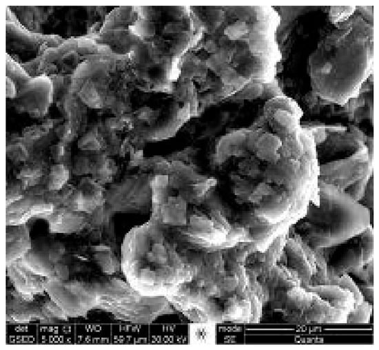
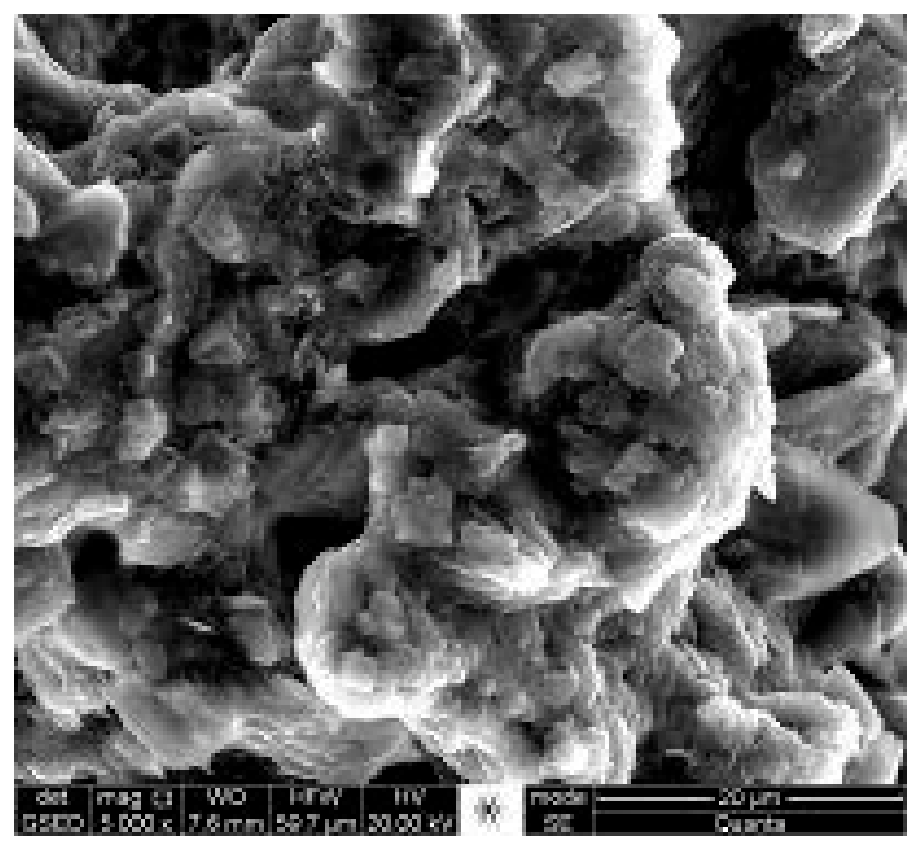
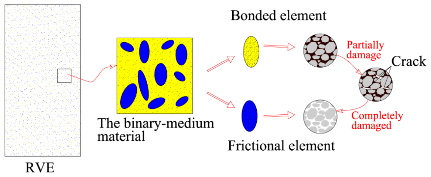
The structured soil is treated as a representative volume element (RVE), which corresponds to a small material point at the macroscopic scale but must be large enough to capture sufficient structural information at the mesoscopic scale. Since the RVE contains a sufficient number of mesoscopic elements, it can be regarded as a continuous, homogeneous medium. In structured soils, the particles are bonded by cementing materials, such as silica (SiO2), calcium oxide (CaO), or gels formed by cement hydration. Examination of Scanning Electron Microscope (SEM) images of structured soils, as shown in Figure 1, reveals an inhomogeneous distribution of soil particles and cements (the light-colored parts) and macropores (the dark-colored parts). According to the binary-medium theory, the RVE is modeled as a complex system of bonded and frictional elements. During initial loading, when the RVE undergoes small deformations, the bonded elements primarily bear the external load. As the load increases, the bonded elements gradually break, transforming into frictional elements. Consequently, the proportion of the load borne by the frictional elements increases.
Figure 1.
SEM image of artificially structured soils. (The materials for preparing sample of artificially structured soils included silty clay, kaolin, cement, and salt particles, and mixed in mass ratio of 65%, 20%, 5%, and 10%. After maintenance in flowing water for 7 days, the section cut through the center of prepared sample was scanned).
2.1. The Local Strain Concentration Tensor Determined by Mesoscopic Deformation Mechanism of Composite Materials
Geotechnical materials, consisting of multiple components, are typically non-continuous and non-homogeneous. As a result, bond breakage, slippage between soil grains, and particle rotation can occur within the meso-structure of structured soils. Based on composite micromechanics, the macro-mechanical behavior of these materials can be predicted by considering variations in composition and microstructure. The corresponding local strain concentration tensor can also be determined.
2.1.1. The Homogenization Theory
The deformation of structured soils is influenced by the internal fabric and the cohesion between soil particles, while shear strength includes both cohesive and frictional components [42,43]. Under external loading, structured soils transition from an elastic to an elasto-plastic state. During this process, the force transmitted through the cementation between soil particles gradually increases, peaking during small deformations. As cementation breaks, the soil begins to display frictional behavior. The friction between soil particles, primarily due to their relative rotation and shear slippage, becomes more significant as deformation increases.
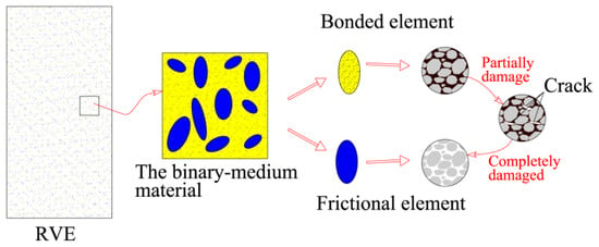
Therefore, within the framework of the binary-medium theory, homogenization theory is applied to establish correlations between the bonded and frictional elements within the RVE (Figure 2). In this paper, unless otherwise specified, all stresses are considered effective stresses. The symbols b and f represent the bonded and frictional elements, respectively.
Figure 2.
Diagram of the mesoscopic compositions for structured soils.
Using , to indicate the local stress tensor and local strain tensor, respectively, the macro average stress, σij, and strain, εij, can be given as follows:
where V is the total volume of the RVE.
The volumes of the bonded and frictional elements are represented by Vb and Vf, respectively; then, V = Vb + Vf.
where and stand for the stress of bonded and frictional elements, and and stand for the strain of bonded and frictional elements, respectively.
Equations (3) and (4) give the relationship of the stress and strain of the RVE and mesoscopic elements, which builds a bridge between macro and meso behaviors of structured soils. Based on this, the incremental stress–strain relation is derived later in the article.
2.1.2. The Local Strain Concentration Tensor
The constrained strain increment refers to the change in strain that occurs in soil when subjected to an external force under specific constraint conditions. The Eshelby tensor is a physical quantity that assumes the inclusion is ellipsoid, and describes the strain relationship between the internal mesoscopic components of a material when it is subjected to external forces.
Assuming that the bonded elements serve as the matrix of the RVE, the Eshelby tensor for elasto-plastic composites can be used to determine the relationship between the local strains of the bonded and frictional elements in structured soils. The soil and cement are structured particles, and the bonded and frictional elements are assumed to be ellipsoid and distributed uniformly. According to the method developed by Eshelby [44] and Peng et al. [45], the expressions for the constrained strain increment and the eigenstrain increment of the frictional elements can be given as follows:
where is the Eshelby tensor [44] of the elasto-plastic medium; the expression is:
where and are, respectively, the tensor of the elasticity modulus and the tangential elasto-plastic modulus of the bonded elements. Since the bonded elements are linear elastic, , and , here, is the Eshelby tensor:
where K and G are the bulk modulus and the shear modulus of the bonded elements, respectively, and v is its Poisson’s ratio.
The stress increment and strain increment of the RVE of structured soils are denoted as and . Considering the interaction between the two kinds of elements, and that the frictional elements are embedded in the bonded elements, the average stress subjected on the bonded elements is marked as instead of . Combining with the Mori–Tanaka method [46], the correlation between the incremental stress of the bonded elements and frictional elements can be provided according to the deformation compatibility condition as the following expression:
where and are, respectively, the strain increment of the bonded and frictional elements.
The constitutive relationship of the frictional elements is expressed as:
where is the stiffness tensor of frictional elements.
The constitutive relationship of the bonded elements is given as follows:
The frictional elements compose the inclusions of the RVE, and are assumed to be ellipsoid according to meso-mechanics, so the constrained strain increment can be expressed as:
where is the elastic constraint stiffness tensor.
From Equation (5), , and the expression of the constrained stress increment and constrained strain increment can be derived from the elastic constitutive law of Eshelby’s theory as:
Then the following expressions are given according to Equations (3) and (4):
Substituting Equations (11) and (12) into Equation (16), the relationship of the local incremental strain between the bonded elements and frictional elements can be obtained:
2.2. Macro–Meso Binary-Medium Constitutive Model for Structured Soils
Based on the binary-medium theory and the stress–strain expressions of the bonded and frictional elements, along with the incremental formulations of the strain concentration tensor in Section 2.1.2, the macro–meso constitutive relationship of structured soils can be deduced as follows.
Constitutive Equation
Considering the breakage of the bonded elements in the RVE, the breakage ratio of the RVE is defined as the volume fraction of the frictional elements, that is, . Therefore, after introducing the breakage ratio, Equations (3) and (4) can be simplified as:
The breakage ratio increases accumulatively with the changing load and deformation of the RVE, hence the value of the breakage ratio can be determined by the stress or strain:
Equations (20) and (21) can be rewritten in the incremental form as follows:
where the superscript number 0 is used to represent the initial state of stress, strain, and breakage ratio in the increment step; and are the initial value of stress of the bonded and frictional elements; and are the initial value of strain of the bonded and frictional elements; dσij and dεij are the stress and strain increment of the RVE; λ0 and dλ are, respectively, the initial value and increment of breakage ratio.
Substituting Equation (18) into Equation (24) gives:
The incremental stress–strain relationship expression of the RVE can be obtained by substituting Equations (11), (12), (18), (19), (25), and (26) into Equation (23):
For the initial loading:
According to Equations (27) and (28), since the local strain concentration tensor has been provided in Section 2.1, three additional sets of parameters need to be determined in the constitutive model: the breakage ratio, and the constitutive relations of the bonded elements and the frictional elements. The process for defining these parameters will be described in the subsequent sections.
3. Determination of Model Parameters Under Triaxial StressConditions
3.1. Constitutive Relationship for the Bonded Elements
Assuming the bonded elements are isotropic and that the stress–strain relationship of the bonded elements is elastic before failure, the relationship between the stress and strain increments can be described by the generalized Hooke’s law as follows:
where Kb and Gb denote the elastic bulk modulus and shear modulus, respectively, and their value can be calculated with the elastic modulus, Eb, and Poisson ratio, vb, of the bonded elements:
3.2. Constitutive Relationship for the Frictional Elements
The frictional elements form when the bonded elements break during the loading process, and their mechanical properties can be considered equivalent to those of remolded soils. Therefore, the relevant parameters are determined based on experimental results for the stress–strain relationships of remolded soils. In this paper, a double yield surface constitutive model is used to describe the elasto-plastic stress–strain behavior of the frictional elements. In this model, the traditional hardening parameters are replaced by a plasticity coefficient, which is calculated using the Duncan–Chang model.
Referring to the research of Lade et al. [47], Sukkarak et al. [17], Wen, and Wang [48,49], the yield functions, f1 and f2, corresponding to the volume and shear deformation, respectively, are expressed as:
where r1 is the model parameter, which can be determined by fitting the curves of the experimental results of remolded soils; Hv and Hs are the volume and shear hardening parameters, respectively, with the following expressions:
where is the plastic volume strain increment of the frictional elements corresponding to f1; is the plastic shear strain increment of the frictional elements corresponding to f2; γ1, γ2, γ3 and γ4 are the model parameters.
Hence, the incremental formations of hardening parameters Hv and Hs are expressed as:
where and are, respectively, the average principal stress and shear stress of frictional stress, and their formulas are given as:
where , and are the principal stresses of the frictional elements.
The derivatives of f1 and f2 are given as:
In this paper, a non-associated flow rule is employed, and the plastic potential function is similar to the yield surface function as follows:
where ψva and ψvb are the dilatancy parameters.
The derivatives of g1 and g2 are given as:
For brevity, two-dimensional vector and matrix notation are adopted for brevity. That is, , , . During the loading process, the volume deformation and shear deformation are caused by the compression yield and shear yield, respectively, and the corresponding increment of plastic strain, dεfp1 and dεfp2, can be determined as follows:
where dA1 and dA2 are the plastic multipliers.
With the consistency condition, i.e., df1 = df2 = 0, the following expressions can be obtained:
that is:
The expression equations of dA1 and dA2 can be given as:
Therefore, the constitutive relations of frictional elements can be expressed as follows:
where Kf and Gf are the bulk modulus and shear modulus, respectively, and their value can be calculated by the elastic modulus Ef and Poisson’s ratio vf:
3.3. The Determination of the Breakage Ratio Based on the Discrete Element Method
In the binary-medium constitutive models proposed by other researchers [37], the breakage ratio is defined using the empirical expression of the Weibull probability distribution function. However, the parameters for the breakage ratio are typically determined through testing and adjustment based on experimental results, without reference to specific data or physical phenomena. Structured soils are not continuous and the soil particles and voids are randomly distributed within the material. Due to the presence of cementing agents, the soil particles are not as loosely dispersed as in sands. Furthermore, it is challenging to observe and statistically analyze changes in cements and voids through physical tests. Existing technologies, such as Scanning Electron Microscopy (SEM) and X-ray scanning, can only capture the internal structure of materials at specific states, rather than recording data throughout the entire loading process.
Assuming that structured soils are granular materials bonded by cements, the Discrete Element Method (DEM) is used to simulate conventional triaxial compression tests on structured soil samples. The simulation results are validated by comparing them with experimental data, ensuring that the simulation can qualitatively reflect the mechanical properties of structured soils. Comprehensive mesoscopic structural information is obtained, including inter-particle contacts and broken cement bonds. By analyzing statistical data on the evolving cement and contact networks, the meso-structural evolution of the simulated samples during loading is characterized. Combining the construction method and definition of the epidemic model, a proportional distribution model for strongly and weakly bonded particles (SW model) is proposed to quantify the breakage rule of the meso-structure. The relevant parameters are then used to define the function of the breakage ratio. Compared to the parameters determined merely through empirical formulas, this method provides a more physically meaningful representation of the breakage ratio by considering the meso-structural evolution of structured soils.
3.3.1. Simulated Sample of Structured Soils
To simulate the stress environment of the structured soil sample, the sample is modeled in three dimensions using the Discrete Element Method (DEM). Both the consolidation and loading processes are carried out in this simulation. A linear contact model is used to represent interactions among particles, and the parameters for simulating structured soils are provided in Table 1.
Table 1.
Simulation parameters for conventional triaxial compression tests of structured soils.
The initial sample of structured soil is modeled as a cube with a side length of 2 cm, with the soil particles idealized as spheres. To ensure even particle distribution within the walls, the pre-set particle size is smaller than the target size. Once the particles have dispersed and reached initial equilibrium, their radius is increased by 10% (to 1.1 times their original size), and the simulation runs for several steps to allow the particles to re-equilibrate. The particle size range is between 0.275 and 0.55 mm. Subsequently, the parallel bond model is applied to simulate inter-particle contact. The structured soil sample is simulated with internal cements and large pores, and its initial void ratio is set to match that of samples prepared in physical tests.
3.3.2. Compression Process of Structured Soils
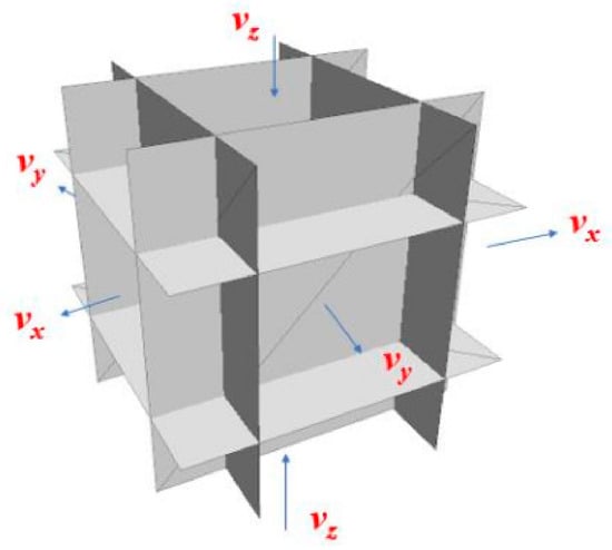
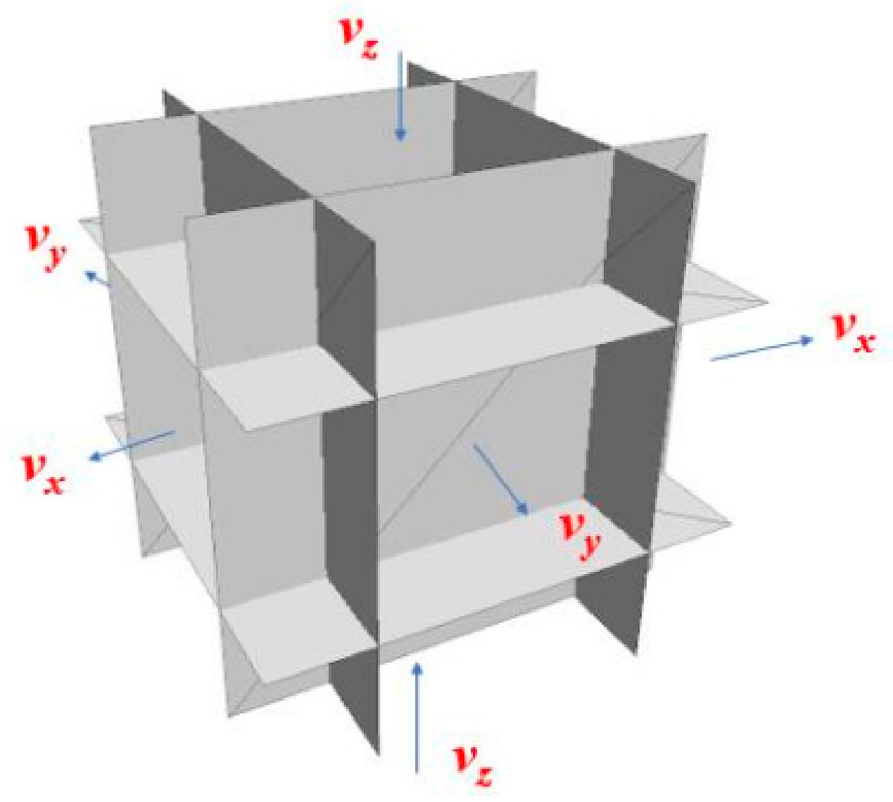
According to the procedure of physical tests, the prepared sample of structured soils is applied isotropically under different confining stresses. By controlling the direction and velocity of the walls through a servo mechanism in the simulation, an isotropic load is applied to the sample. The loads acting on the sample can be calculated by the reaction forces on the walls, and the loading process is completed when the load reaches a given value and the particles are in an equivalent static equilibrium. After this step, the simulated sample is compressed under both drained and undrained conditions. The undrained condition is realized by controlling the volume of the sample constant in the simulations, and the pore-water pressure is the calculated difference between the determined confining pressure and the lateral effective pressure [49,50]. The servo method to apply loads is different for drained and undrained compression tests of structured soils (as shown in Figure 3): for the drained test, the stress on the lateral walls is kept constant by moving the lateral walls; for the undrained test, the volume of the sample is kept constant by controlling the movement of the lateral walls according to the direction and velocity of the horizontal walls. According to research of Perez et al. [51], the inertial number (I) is determined using the axial strain ratio (), the maximum diameter (dm), particle density (dp), and the mean stress (p′) of sample. That is, , where the strain rate of simulation is set at 0.5%, and it is calculated that I < 1.0e−4, which reasonably represents the simulation at equivalent static equilibrium during loading.
Figure 3.
Diagram of loading method of undrained tests.
3.3.3. Simulation Results of Conventional Triaxial Tests of Structured Soils
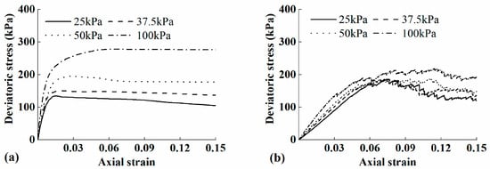
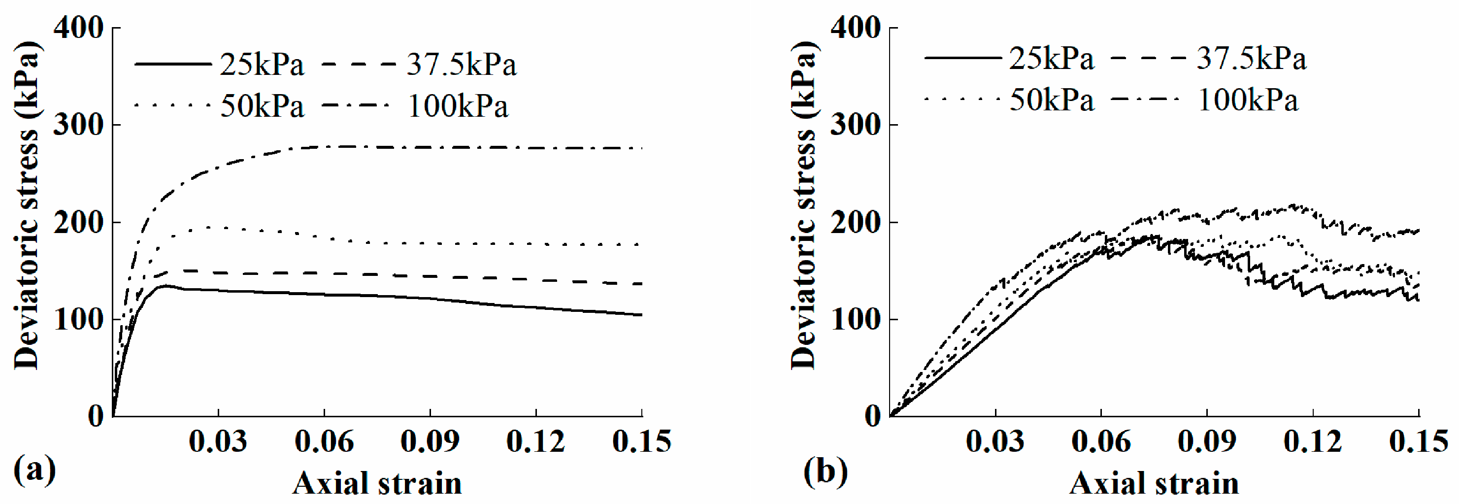
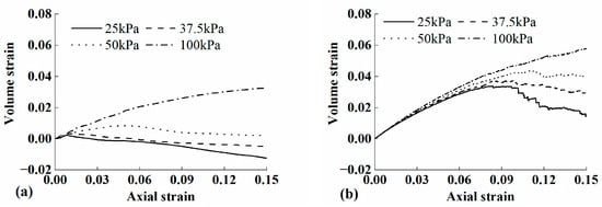
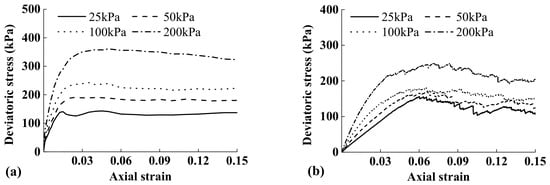
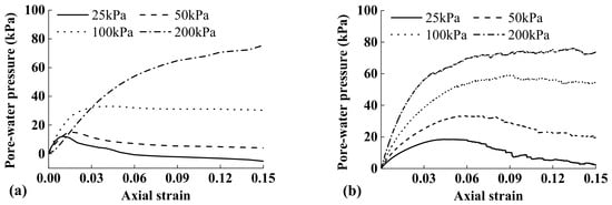
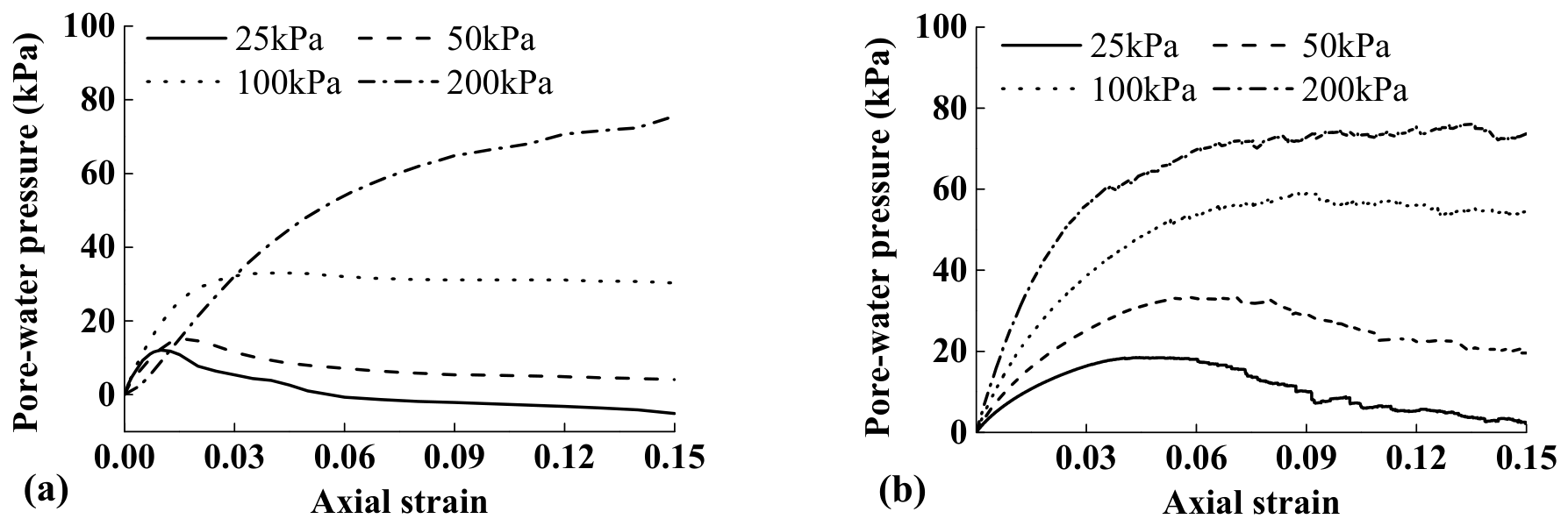
By comparing the simulated results with the experimental data, as shown in Figure 4, Figure 5, Figure 6 and Figure 7, we observe the variations in deviatoric stress and volume strain with axial strain. These figures demonstrate that the simulation qualitatively captures the macro-mechanical behavior of structured soils during triaxial compression tests, both under drained and undrained conditions. For the drained tests, the simulation shows pronounced strain softening at lower confining stresses, with the sample’s volume transitioning from contraction to dilation. At higher confining stresses, the strain hardening effect diminishes, and the volume change consistently trends toward contraction. For the undrained conditions, the simulation results indicate that strain softening persists. The pore water pressure initially increases and then decreases under lower confining stress. However, under higher confining stress, the pore water pressure increases monotonically.
Figure 4.
Variation of the deviatoric stress with axial strain of (a) tests (He et al. [51]) and (b) simulations under the drained condition.
Figure 5.
Variation of the volume strain with axial strain of (a) tests (He et al. [51]) and (b) simulations under the drained condition.
Figure 6.
Variation of the deviatoric stress with axial strain of (a) tests (Li et al. [52]) and (b) simulations under the undrained condition.
Figure 7.
Variation of the pore-water pressure with axial strain of (a) tests (Li et al. [52]) and (b) simulations under the undrained condition.
3.3.4. Differentiation of Particles in the Simulated Sample
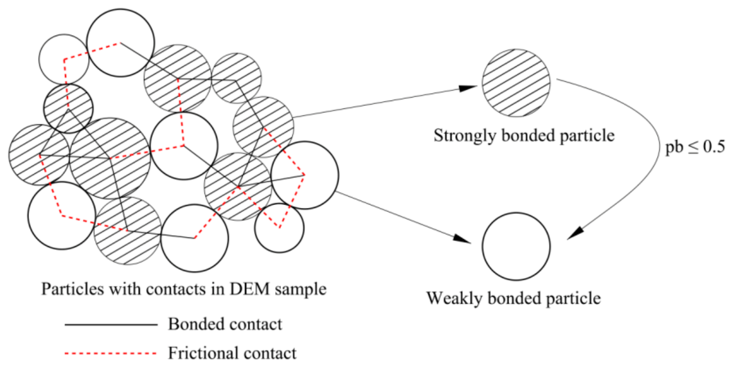
In the simulation, all inter-particle contacts in the initial sample are cemented. During the loading processes, cements may break if the contact force exceeds their strength, causing the contacts to translate into be linear, unbonded contacts. For clarity, the intact cemented contacts are referred to as “bonded contacts,” while the broken ones are referred to as “frictional contacts.”
Due to the nature of the Discrete Element Method (DEM), the particles are treated as rigid and do not deform or break during loading. Therefore, the analysis of the mechanical properties and meso-structure of the sample primarily focuses on the spatial movement of particles and the changes in inter-particle contacts. For individual particles, the effects of bonded and frictional contacts on their movement are distinctly different. Bonded contacts provide tensile strength and constrain relative movement between particles, thereby enhancing both shear and tensile strength. As the proportion of bonded contacts decreases below a certain threshold, the particle becomes less constrained and less supported. These particles, similar to nodes in a contact network, are defined as “weakly bonded particles,” while those with a higher proportion of bonded contacts are defined as “strongly bonded particles.”
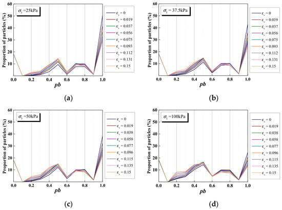
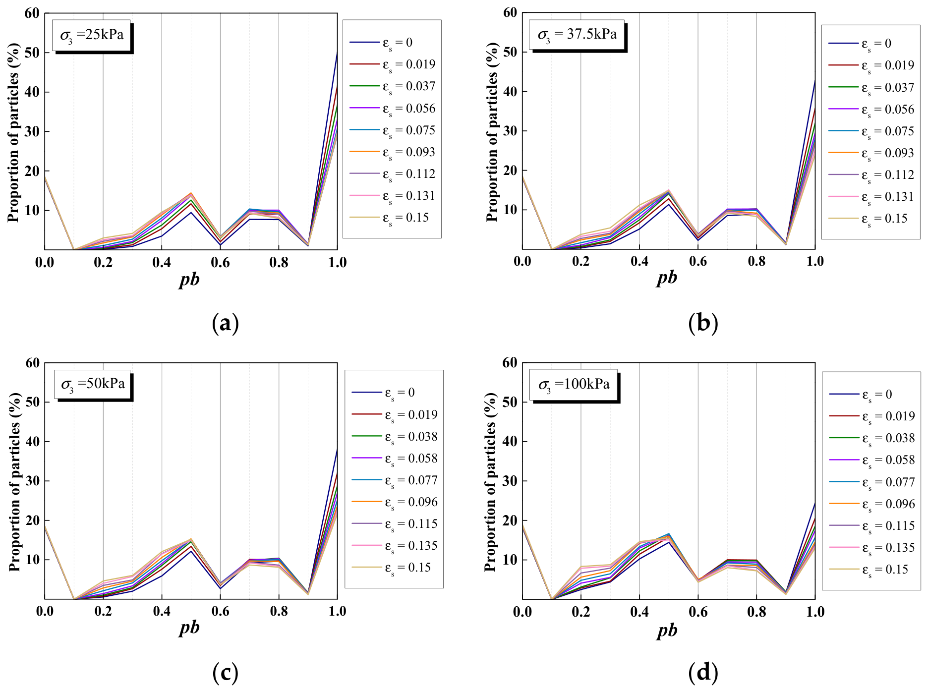
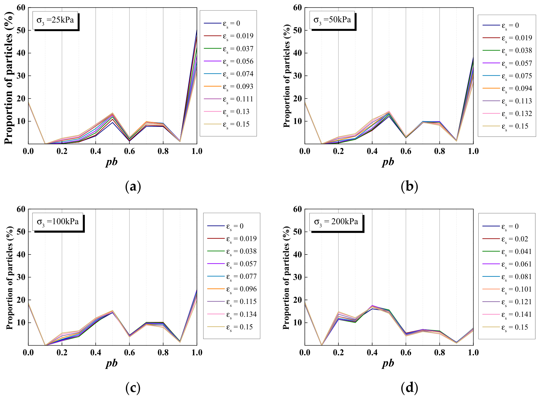
The evolution of the proportion of bonded contacts (pb) for particles in the sample during loading is tracked and recorded, with distribution diagrams presented in Figure 8 and Figure 9. The results show that during loading, the percentage of particles with a proportion of bonded contacts less than or equal to 0.5 increases. By the time the strain reaches 15%, more than 50% of the particles have a proportion of bonded contacts of 0.5 or less. Based on this observation, a threshold of 0.5 is chosen to distinguish strongly bonded particles from weakly bonded particles. Particles with pb > 0.5 are defined as the strongly bonded, while the others are defined as the weakly bonded particles (Figure 10), i.e.,
where npcb is the number of the bonded contacts of a particle; npc is the number of the total contacts of a particle.
Figure 8.
The distribution diagrams of the proportion of the bonded contacts (pb) for particles in sample during loading under the drained condition (): (a) σ3 = 25 kPa; (b) σ3 = 37.5 kPa; (c) σ3 = 50 kPa; (d) σ3 = 100 kPa.
Figure 9.
The distribution diagrams of the proportion of bonded contacts (pb) for particles in sample during loading under the undrained condition (): (a) σ3 = 25 kPa; (b) σ3 = 50 kPa; (c) σ3 = 100 kPa; (d) σ3 = 200 kPa.
Figure 10.
Schematic diagram for differentiation of particles.
3.3.5. The Distribution Model of Proportion of Strongly and Weakly Bonded Particles
In this paper, inspired by definitions from complex network theory, particles and inter-particle contacts in the simulated sample are simplified as vertices and edges in a network [50,51,52,53,54,55]. Additionally, the SIS epidemic model (SIS model) [56] is adapted to define the distribution model of strongly and weakly bonded particles. In the SIS model, vertices can be either infected or susceptible, and their states change due to infection or recovery processes. Assuming that all vertices are uniformly distributed across an area, the disease spreads from infected vertices to other vertices through edges. According to the mean-field theory of networks, the dynamic behavior of vertices with the same degree (ki, the number of edges connected to the i-th vertex) is assumed to be consistent, enabling the use of the equalization method. Let Ik represent the density of infected vertices connected to k edges. The SIS model can be approximately formulated based on the heterogeneous mean-field approach as follows:
where is the rate that the density of infected vertices whose degree is k increases; ð(k) is the infection rate, which presents the probability that a susceptible vertex contacts with an infected vertex and becomes infected, which is related to the degree of the vertex; and ð(k) = kA(k); here, A(k) is the probability that one edge of the susceptible vertex connects to an infected vertex and become infected; X is the rate that the edge contacts the infected vertex and spreads the decrease, which can be approximately as the proportion of edges connected to the infected vertex of all edges, i.e., , where ⟨k⟩ is the average degree of the contact network; n is the maximum value of the degree; kT(k) represents the average value of edge spread decrease of infected vertices; pk is the probability that the degree of a vertex is k; and δ is the recovery ratio of infected vertices, which is usually set to 1.
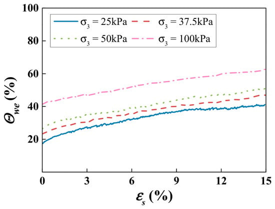
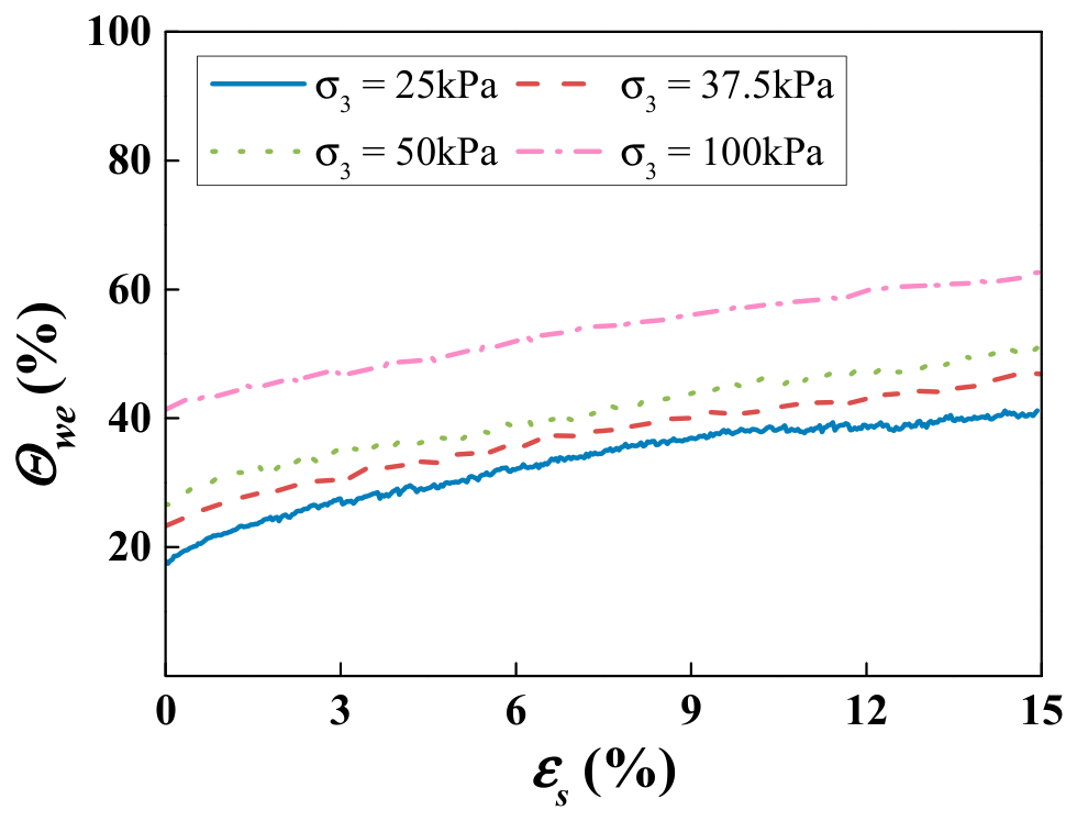
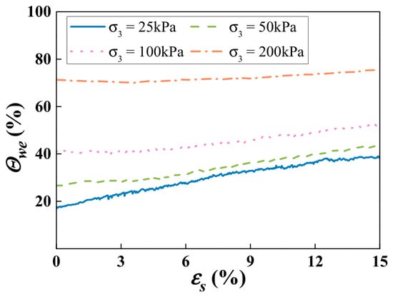
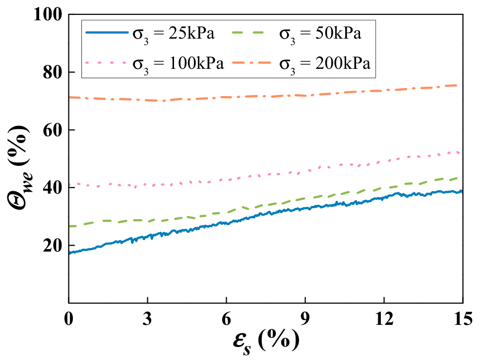
Given the threshold that distinguishes strongly and weakly bonded particles, the statistical results showing the changing proportion of weakly bonded particles () with shear strain (εs) can be obtained from both drained and undrained simulations, as shown in Figure 11 and Figure 12. Unlike the simple breakage ratio of cements, the statistics of weakly bonded particles account for the degree distribution in the contact network, which reflects the variation in broken cements and the distribution of contacts at the mesoscopic scale during loading. From the figures, it is evident that the rate of increase in the proportion of weakly bonded particles is higher in the drained simulation compared to the undrained simulation.
Figure 11.
Evolution of with shear strain (εs) under the drained condition.
Figure 12.
Evolution of with shear strain (εs) under the undrained condition.
Referring to the SIS model, the symbol S is used to represent the strongly bonded particles and the symbol W represents the weakly bonded particles, and the distribution model of proportion of the strongly and weakly bonded particles (SW model) is established to describe change of proportion of number of weakly bonded particles and proportion of number of weakly bonded particles () with εs. The formulation is given as follows:
From Figure 11 and Figure 12, it can be observed that the number of weakly bonded particles increases during loading. In this paper, the transformation of weakly bonded particles into strongly bonded particles was not considered. However, the meso-structures of the samples after isotropically loading under different confining stresses are different, and this meso-structure evolution will influence the subsequent compression process. Therefore, κ is defined as the influence factor of the initial meso-structure on the increasing rate of weakly bonded particles. indicates the percentage of strongly bonded particles. Referring to definitions in complex network theory, gsw is the probability function of strongly bonded particles transforming into weakly bonded particles, which is expressed as , where Γ is the probability of a single strongly bonded particle contacting a weakly bonded particle and becoming weak under its influence. ⟨d⟩ is the average degree of the contact network, expressed as f, where ⟨d⟩s and ⟨d⟩w are the average degrees of strongly and weakly bonded particles during loading, respectively. indicates the probability that a contact of a weakly bonded particle connects to another particle and transfers the damage. This can be approximately represented as the proportion of frictional contacts to the total contacts in the contact network, and is expressed as follows:
where ϕi = ηi, η is the probability of the weakly bonded particle spreading cement breakage through a contact, and P(i) is the percentage of particles whose degree is i, i.e., . So, Equation (69) can be simplified as . Considering η as a material constant, its value is adjusted based on the simulation results, i.e., η = 0.96.
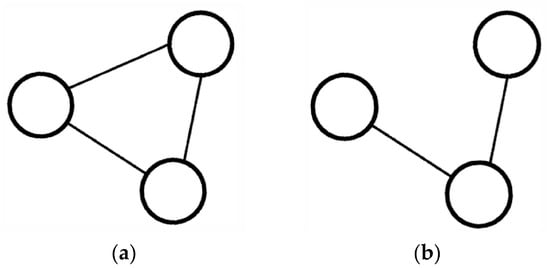
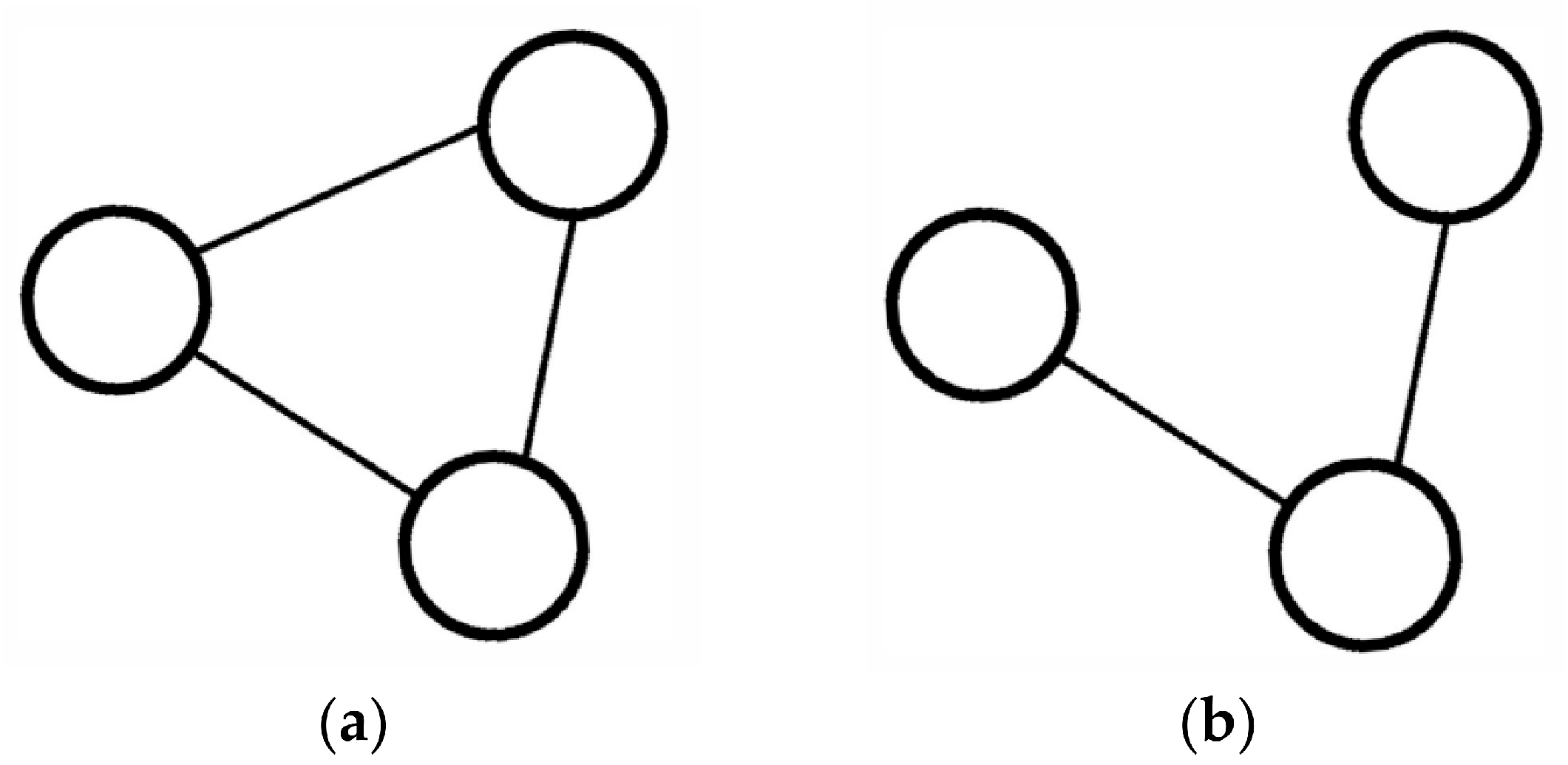
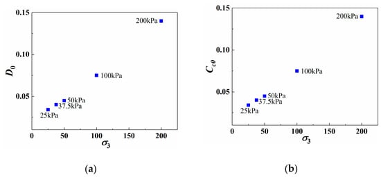
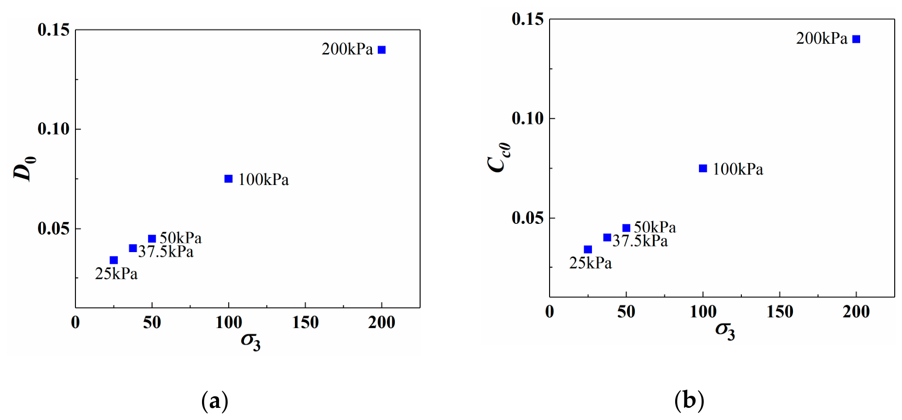
To quantify the support among particles, the clustering coefficient from complex network theory is adopted. According to the research of Sun et al. [57], it is defined as the ratio of triangles (Figure 13a) to triads (Figure 13b) in the network. As shown in Figure 14, under the higher confining pressure, both the average degree and the clustering coefficient are larger, resulting in a denser contact network with a higher proportion of closed triangles. Consequently, particles are more strongly supported by their neighboring particles, reducing the probability of strongly bonded particles transforming into weakly bonded particles. Therefore, the parameter Γ is smaller and is assumed to be negatively correlated with the clustering coefficient of strongly bonded particles. Consequently, the logarithmic relationship between Γ and the average clustering coefficient of the strongly bonded particles, Cst, can be expressed as follows:
where and are material constants.
Figure 13.
Geometric graphs of (a) triangles and (b) triads (Sun et al. [57]).
Figure 14.
Value of (a) average degree (D0) and (b) clustering coefficient (Cc0) after consolidation under different confining stresses.
In addition, more cementation bonds are broken within the specimen under higher confining pressure. However, the proportion of weakly bonded particles and frictional contacts both increase after consolidation, and the particles come into closer contact. As a result, local damage to cementation during loading has less impact on the overall contact network. Considering the meso-structure influenced by the confining pressure, the value of is negatively correlated with the initial clustering coefficient before loading. The calculation formula for is as follows:
where o1 and o2 are model parameters.
η, , κ, and, from Cst, C0 are converted from the SW parameters, and the value is adjusted by comparing with experimental results of structured soils. η = 0.96 is the value that reproduces the simulated –εs curves of Figure 11 and Figure 12, while ς1, ς2 in Equation (70) and o1, o2 in Equation (71) are obtained by linear regression of and κ against lnCst and C0.
3.3.6. Determination of the Parameters of the Breakage Ratio Based on Evolution of Meso Structure
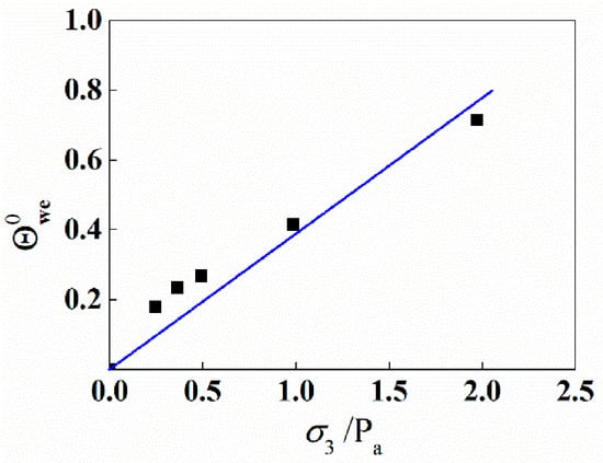
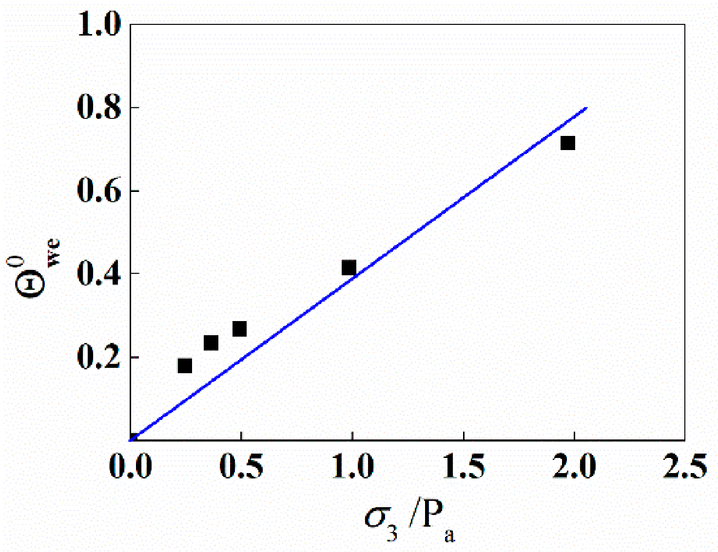
According to the simulated results, the damage of bonds and distribution of the bonding contacts and frictional contacts can be reflected. The initial values of and are larger under the higher confining pressure (data points marked with squares), and is linearly correlated with the confining pressure as shown by line in Figure 15.
Figure 15.
The evolution of with σ3 (Pa is the standard air pressure).
During the loading process, increases monotonically. In the binary-medium constitutive model, the breakage ratio λ varies from λ0 to 1 incrementally. From others’ research [42,43], λ is difficult to measure in physical experiments or scanning tests, and its initial value, λ0, is usually assumed as 0 without considering the damage caused by the consolidation process. In this paper, λ0 is determined by ; therefore, the relationship expression of λ0 and the confining pressure, σ3, can be given as follows:
where ω is the material constant, whose value is not affected by the drainage condition, and Pa represents the standard atmospheric pressure.
In terms of the investigation of previous research about the damage variable of geotechnical materials and empirical equation, the function of the breakage ratio is determined to be the Weibull distribution. In Equation (72), The volume fraction of the frictional elements at the end of consolidation is identified with the number fraction of weakly bonded particles in the simulated sample, so that the damage caused by consolidation enters the model through . The calculation formula of the breakage ratio is assumed to be only connected with the shear strain, εs, as follows:
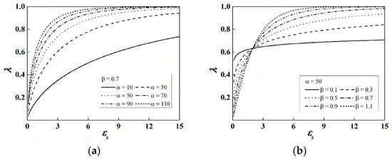
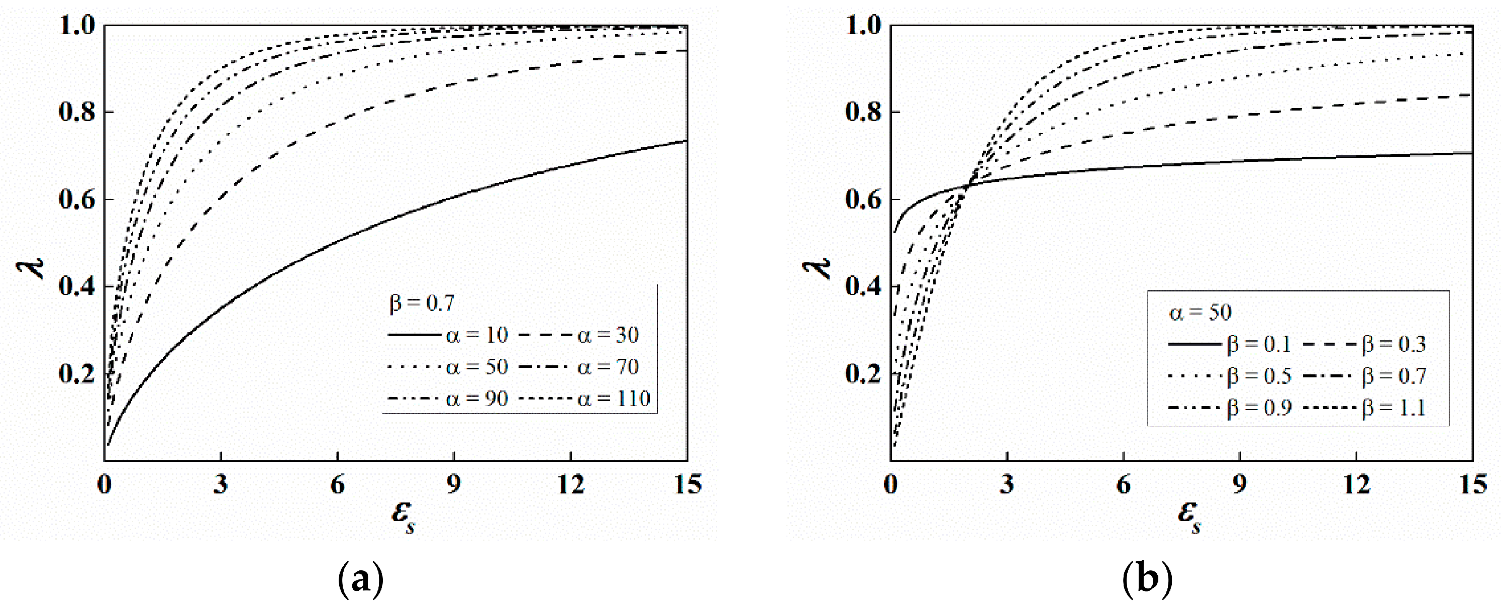
where α and β are the model parameters. In order to relate the breakage ratio to the parameters of the meso structure, the sensitivity of α and β is analyzed. As shown in Figure 16, the increasing tendency of the curve of λ in the whole loading process is mainly influenced by β. λ has a faster increase in the initial stage with lager α or smaller β, and the final value of β is larger with lager α or β.
Figure 16.
The evolution curves of λ with εs under different values of model parameters: (a) α; (b) β.
As described in Section 3.3.5, η, , and κ are the parameters which control the variation of in the SW model, and they can be calculated by numerical simulation. The method to determine parameters of the meso structure is used to derive equations of α and β. α is the influence factor of the confining pressure on the value of the breakage ratio, and in the simulated sample during the loading process, the higher the confining pressure, the larger the normal and tangential contact forces, and the bonds between particles are more easily broken. Therefore, the relationship expression of α with σ3 can be established as follows:
where ι1 and ι2 are the material constants.
Combing the determination of and κ, which control the increase rate of the proportion of the weakly bonded particles, and the quantitative values of C0 and Cst from the simulation, the expression of β can be proposed as follows:
where and are material constants, which are determined according to physical test results. Equations (74) and (75) prescribe how α and β vary with the confining pressure and with the meso-structural descriptors.
In this section, the initial value of breakage ratio is established from the DEM statistics after consolidation, and the evolution rate is governed by the SW model. The macroscopic value of the breakage ratio is then parameterized by the Weibull function, and the parameters α and β are linked to confining pressure.
4. Model Verification
In this section, we reference the physical test results of He et al. [51] and Li et al. [52], which include triaxial compression tests conducted under both drained and undrained conditions. The structured soil samples in these experiments are prepared with silty clay, kaolin clay, cement, and highly purified salt particles, and inter-particle bonds and voids are generated from cement and salt particles, respectively. These results are used to determine the constitutive model parameters for the bonded and frictional elements. Additionally, the parameters for the breakage ratio are derived based on the simulation results and the SW model.
4.1. Constitutive Model Parameters of the Bonded Elements
It is assumed that, in the initial stage, the load is primarily carried by the bonded elements, which exhibit linearly elastic properties. The elastic modulus is determined based on the results of the drained triaxial compression tests. Therefore, the secant modulus and Poisson’s ratio at 0.3% axial strain (εa = 0.3%) are selected as the elastic modulus (Eb) and Poisson’s ratio (vb) of the bonded elements. Since both the elastic modulus and Poisson’s ratio vary with confining stress, the final values of the model parameters are presented as follows: , .
4.2. Constitutive Model Parameters of the Frictional Elements
Once the bonded elements break and transform into frictional elements, the stress–strain relationship of the frictional elements becomes elasto-plastic. The bonds between particles are broken, resulting in weak inter-particle cohesion in the remolded soils. Consequently, these soils can be treated as composed entirely of frictional elements, with their mechanical properties defined by empirical findings from tests on remolded soils. Following the approach outlined by Shen et al. [40], the elastic modulus (Ef) and Poisson’s ratio (vf) of the frictional elements are determined according to secant values of stress–strain and volumetric strain curves at 0.3% axial strain (εa = 0.3%) as , , while the remaining parameters are adjusted by comparing with experimental data [51], as outlined in Table 2.
Table 2.
Value of constitutive model parameters of the frictional elements.
In Table 2, all parameters are dimensionless. r1 and r2 are shape parameters of the yield and potential surfaces; γ1, γ3, and γ4 keep linear regression against ln(σ3/Pa). The formulas of the hardening parameters γi and the dilatancy parameters ψ are determined according to the stress–strain and volumetric strain curves of remolded soils, and the values are adjusted finally by test results of structured soils.
4.3. Parameters of the Breakage Ratio
Based on the methods described in Section 3.3.6, the calculation equations of the breakage ratio are given, and the determined parameters are shown in Table 3.
Table 3.
Value of parameters of the breakage ratio.
In Table 3, all parameters are dimensionless. ω is the slope of the linear relation between and σ3, multiplied by Pa, and it is determined according to the DEM statistics after consolidation, common to both drainage conditions. ι1, ι2, , and are calibration constants rather than independently measured quantities, and they are obtained by adjusting α and β until the resulting λ(εs) reproduces the measured stress–strain and volumetric response of the structured samples, after which the constants are fixed and applied unchanged to all confining pressures of the same drainage condition.
4.4. Verification of the Constitutive Model
For undrained conditions, the constitutive model is validated by comparing the curves of the shear stress (σs), volumetric strain (εv), and pore-water pressure (u) versus the shearing strain (εs) of tests with calculated results under different confining pressures, and the confining pressure σ3 and the volume of the sample are kept constant, so that dσ3 = 0 and dεv = 0 for the drained condition, and the incremental pore-water pressure can be calculated by du = −dσ′3 for the undrained condition.
The independent variable of the formula is dεs, with the drained case converted from stress control and the undrained case closed by the constant-volume condition together with du. Within each increment, the two yield surfaces of Equations (32) and (33) are first examined in order to establish which of them is active, the three possibilities being volumetric yielding with f1 = 0 and f2 < 0, shear yielding with f2 = 0, and f1 < 0, and simultaneous yielding with f1 = f2 = 0. When a single surface is active, the plastic multiplier is given explicitly by Equation (57) or Equation (58), with hv and hs from Equations (59) and (60); these coefficients depend only on the current stress state, so the increment of frictional stress follows directly from Equation (61). When both surfaces are active, substitution of Equations (51) and (52) into the two consistency conditions, Equations (55) and (56), yields two linear equations in dA1 and dA2, which are solved simultaneously as a two-by-two system. The strain increment of the bonded elements then follows from Equations (25) and (26), the macroscopic stress increment from Equation (27), and Cfb and are updated from Equations (19) and (26) at the end of the step. The breakage ratio is updated explicitly at the end of each step. Differentiating the breakage function with respect to the shear strain and inserting the current value gives the increment of λ for the step. Within each increment, λ is evaluated from Equation (73) at the end of the step; the increment follows as dλ = λ(εs+Δεs) − λ(εs), and the value obtained enters Equations (19), (26) and (27) at the beginning of the next step.
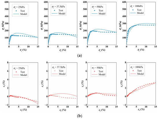
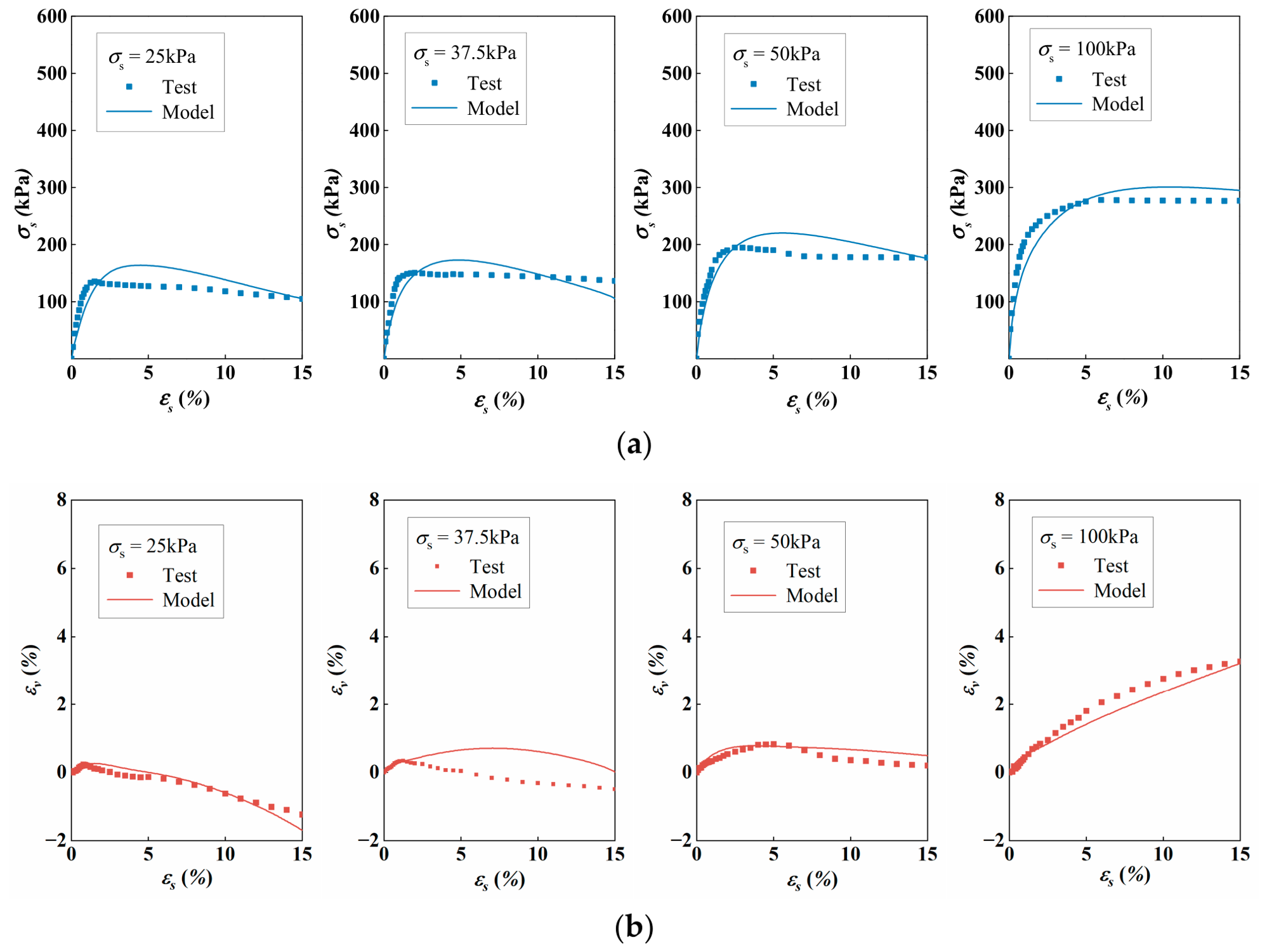
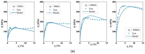
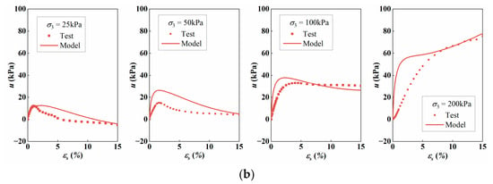
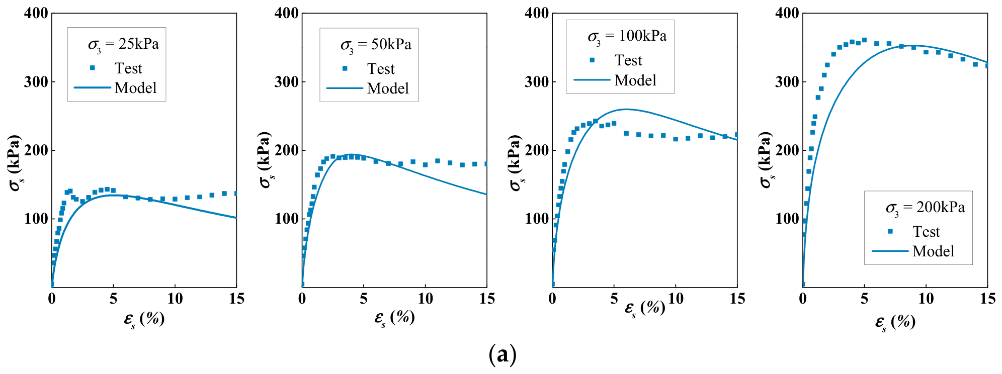
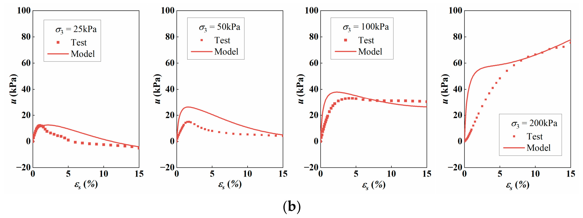
The test results under both drained and undrained conditions are compared with using the constitutive model proposed here. By substituting the model parameters and their initial values into the binary-medium constitutive equation (Equation (61)), the incremental calculations can be completed. Using the cumulative values and iterative methods, the stress, deformation, and pore-water pressure can be updated after each iteration step. The comparisons between the model and experimental results are presented in Figure 17 and Figure 18.
Figure 17.
Comparisons of model and experiment results under the drained condition. (a) Curves of shear stress with shearing strain; (b) Curves of volumetric strain with shearing strain.
Figure 18.
Comparisons of model and experiment results under the undrained condition. (a) Curves of shear stress with shearing strain; (b) Curves of pore-water pressure with shearing strain.
The results shown in these figures indicate that the binary-medium constitutive model, based on the meso-scale development mechanism, effectively captures the mechanical responses of structured soils under both drained and undrained conditions. In drained tests, the model accurately reproduces phenomena such as strain softening and the transition of volume deformation from contraction to expansion. As the confining pressure increases, the degree of strain softening and volume dilatancy diminishes, leading to higher shear strength. Conversely, in undrained tests, the model successfully captures strain softening and the initial increase followed by a decrease in pore-water pressure under lower confining pressures. At higher confining pressures, the model reproduces a monotonically increasing pore-water pressure.
To make the comparison more informative than a visual impression, the characteristic quantities—the peak shear stress σs,max, the shear strain at peak εs,p, and, for the undrained tests, the peak pore-water pressure umax—are analyzed, rather than a global indicator. The maximum difference of calculated and measured peak strengths is approximately 20 kPa. The maximum difference of the volume strain at peak is approximately 0.5% for drained conditions, and the difference in pore water pressure is 10 kPa or less under undrained conditions. The volumetric deformation of the RVE is carried by the frictional elements through the dilatancy parameter ψv of Equation (46), the bonded elements being linear elastic and therefore producing no irreversible volume change; the collapse of inter-particle voids that accompanies bond breakage is not represented as a separate volumetric mechanism and can only be reproduced indirectly through the evolution of λ. The model imposes a uniform pore-water pressure over the sample, whereas the measured quantity is a boundary average over a specimen in which the pore pressure is not uniformly distributed, particularly after the onset of localization. In addition, the initial breakage ratio increases with confining pressure through Equation (72), so that at higher confining pressures, a larger part of the cementation has already been degraded before shearing begins; the model then gives a monotonically increasing pore pressure at high confining pressure and a peak followed by a decrease at low confining pressure, and the confining pressure at which this transition occurs is governed by ω and α, which were calibrated rather than measured. The transition is therefore reproduced qualitatively but not located precisely, and this is the main source of the residual difference in Figure 18b.
A limitation of the homogenization scheme should also be acknowledged. Equations (7)–(9) are the Eshelby tensor of an ellipsoid inclusion, and the concentration tensors of Equations (19) and (26) follow from the Mori–Tanaka estimate for an inclusion embedded in a continuous matrix at a small or moderate inclusion fraction. The bonded elements are always treated as the matrix and the frictional elements as the inclusions, whereas physically it is the bonded phase that disappears: by the end of the tests, λ exceeds 0.9, so less than 10% of the RVE remains bonded and the connected load-bearing skeleton is the frictional phase, yet the formulation continues to regard the bonded phase as the matrix. A breakage-dependent or self-consistent homogenization scheme, with the matrix and inclusion roles interchanged as λ increases, together with a tensorial rather than scalar description of breakage, may be a significant improvement on this work.
Overall, the binary-medium constitutive model can reasonably replicate key parameters, including peak strength, residual strength, shear strain at peak strength, volume strain, and peak pore-water pressure, and reproduces the mechanical behaviors and deformation properties of structured soils. However, some discrepancies are observed in the pore-water pressure curves between the calculated and experimental results. These differences are attributed to the uneven distribution of increasing pore-water pressure within the experimental samples.
5. Conclusions
Based on the binary-medium constitutive model, micromechanics of composites, and microscopic damage mechanisms, a novel macro–meso binary-medium constitutive model is developed in this study. Key findings include the following: (i) The proposed model accurately captures the strain softening and hardening behavior of structured soils under both drained and undrained conditions. (ii) Using the Mori–Tanaka method and homogenization theory, equations describing the incremental strain of the bonded elements, frictional elements, and Representative Volume Element (RVE) are derived. (iii) Breakage ratio parameters are determined through Discrete Element Method (DEM) simulations using the SW model, which quantifies changes in the contact network and cement within the simulated structured soils. (iv) By comparing the model with experimental results, it is demonstrated that the constitutive model has an improved ability to reproduces the mechanical properties and deformation characteristics of structured soils under various drained conditions.
Author Contributions
Conceptualization, Y.S. and E.L.; methodology, E.L.; software, Y.S. and Y.X.; validation, Y.S., E.L., and J.W.; formal analysis, Y.S. and Y.X.; investigation, Y.S.; resources, Y.S., J.W., and E.L.; data curation, Y.S., E.L., and J.W.; writing—original draft preparation, Y.S.; writing—review and editing, Y.S.; visualization, Y.S.; supervision, Y.S.; project administration, E.L.; funding acquisition, E.L. and J.W. All authors have read and agreed to the published version of the manuscript.
Funding
This work was supported by funding from the National Key Research and Development Program of China (Item No. 2023YFC3206103), the National Natural Science Foundation of China (NSFC) (Grant No. 12372376), and the post-doctoral innovation practice positions in Hubei province (No. 2024HBBHCXB086).
Institutional Review Board Statement
Not applicable.
Informed Consent Statement
Not applicable.
Data Availability Statement
The datasets used and analyzed during the current study are available from the corresponding authors upon reasonable request.
Acknowledgments
The author would like to thank Li Yuan for supporting this work.
Conflicts of Interest
Authors Yi Sun, Jundong Wu, and Yunpeng Xu were employed by the company State Key Laboratory of Water Resources Engineering and Management, Changjiang Institute of Survey, Planning, Design and Research Corporation. The remaining authors declare that the research was conducted in the absence of any commercial or financial relationships that could be construed as a potential conflict of interest.
References
- Sangrey, D.A. Naturally cemented sensitive soils. Géotechnique 1972, 22, 139–152. [Google Scholar] [CrossRef] [Scilit]
- Leroueil, S.; Vaughan, P.R. The General and Congruent Effects of Structure in Natural Soils and Weak Rocks. Géotechnique 1990, 40, 467–488. [Google Scholar] [CrossRef] [Scilit]
- Sun, D.A.; Chen, B.; Wei, C.F. Effect of Fabric on Mechanical Behavior of Marine Clays. Mar. Georesources Geotechnol. 2014, 32, 1–17. [Google Scholar] [CrossRef] [Scilit]
- Burland, J.B. On the compressibility and shear strength of natural clays. Géotechnique 1990, 40, 329–378. [Google Scholar] [CrossRef] [Scilit]
- Coop, M.R.; Gasparre, A.; Nishimura, S.; Jardine, R.J. The influence of structure on the behaviour of London Clay. Géotechnique 2007, 57, 19–31. [Google Scholar] [CrossRef] [Scilit]
- Khalid, U.; Ye, G.L.; Yadav, S.K.; Yin, Z.Y. A simple experimental method to regain the mechanical behavior of naturally structured marine clays. Appl. Ocean Res. 2019, 88, 275–287. [Google Scholar] [CrossRef] [Scilit]
- Le, T.; Airey, D. Mechanical behaviour of a weakly structured soil at low confining stress. Géotechnique 2023, 73, 128–142. [Google Scholar] [CrossRef] [Scilit]
- Krieg, R.D. A Practical Two Surface Plasticity Theory. J. Appl. Mech. 1975, 42, 641–646. [Google Scholar] [CrossRef] [Scilit]
- Bardet, J.P. Bounding surface plasticity model for sands. J. Eng. Mech. 1986, 112, 1198–1217. [Google Scholar] [CrossRef] [Scilit]
- Rahimi, M.; Chan, D.; Nouri, A. Constitutive model for monotonic and cyclic responses of loosely cemented sand formations. J. Rock Mech. Geotech. Eng. 2018, 10, 740–752. [Google Scholar] [CrossRef] [Scilit]
- Horpibulsuk, S.; Liu, M.D.; Liyanapathirana, D.S.; Suebsuk, J. Behaviour of cemented clay simulated via the theoretical framework of the Structured Cam Clay model. Comput. Geotech. 2010, 37, 1–9. [Google Scholar] [CrossRef] [Scilit]
- Liu, W.H.; Li, W.G.; Zhang, H.Y.; Lin, X.Y.; Kong, G.; Wang, L.; Hu, P. A critical state constitutive model for unsaturated structured soils. Comput. Geotech. 2022, 152, 104993. [Google Scholar] [CrossRef] [Scilit]
- Zhao, R.; Zhou, A.; Yao, Y.P. The UTUH model: A time-dependent unified hardening constitutive model for unsaturated soils. Acta Geotech. 2024, 19, 1649–1666. [Google Scholar] [CrossRef] [Scilit]
- Jia, P.J.; Khoshghalb, A.; Chen, C.; Zhao, W.; Dong, M.M.; Esgandani, G.A. Modified Duncan-Chang Constitutive Model for Modeling Supported Excavations in Granular Soils. Int. J. Geomech. 2020, 20, 04020211. [Google Scholar] [CrossRef] [Scilit]
- Lai, Y.M.; Liao, M.K.; Hu, K. A constitutive model of frozen saline sandy soil based on energy dissipation theory. Int. J. Plast. 2016, 78, 84–113. [Google Scholar] [CrossRef] [Scilit]
- Liu, X.S.; Ning, J.G.; Tan, Y.L.; Gu, Q.H. Damage constitutive model based on energy dissipation for intact rock subjected to cyclic loading. Int. J. Rock Mech. Min. Sci. 2016, 85, 27–32. [Google Scholar] [CrossRef] [Scilit]
- Sukkarak, R.; Pramthawee, P.; Jongpradist, P. A modified elasto-plastic model with double yield surfaces and considering particle breakage for the settlement analysis of high rockfill dams. KSCE J. Civ. Eng. 2016, 21, 734–745. [Google Scholar] [CrossRef] [Scilit]
- Wu, J.Y.; Li, J.; Faria, R. An energy release rate-based plastic-damage model for concrete. Int. J. Solids Struct. 2006, 43, 583–612. [Google Scholar] [CrossRef] [Scilit]
- Cotecchia, F.; Chandler, R.J. The influence of structure on the pre-failure behaviour of a natural clay. Géotechnique 1997, 47, 523–544. [Google Scholar] [CrossRef] [Scilit]
- Amorosi, A.; Rampello, S. An experimental investigation into the mechanical behaviour of a structured stiff clay. Géotechnique 2007, 57, 153–166. [Google Scholar] [CrossRef] [Scilit]
- Jiang, M.J.; Li, T.; Cui, Y.J.; Zhu, H.H. Mechanical behavior of artificially cemented clay with open structure: Cell and physical model analyses. Eng. Geol. 2017, 221, 133–142. [Google Scholar] [CrossRef] [Scilit]
- Zhou, C.; Yin, J.H.; Chen, T.L.; Chen, S.S.; Shen, Z.J. Elastic visco-plastic and damaging analysis of structured soil. In Proceedings of the 3rd International Conference on Soft Soil Engineering, Hong Kong, China, 6–8 December 2001. [Google Scholar]
- He, K.S.; Shen, Z.J. Elasto-viscoplastic damage model for structural clays. Hydro-Sci. Eng. 2002, 4, 7–13. [Google Scholar]
- Pinyol, N.M.; Vaunat, J.; Alonso, E.E. A constitutive model for soft clayey rocks that includes weathering effects. Géotechnique 2007, 57, 137–151. [Google Scholar] [CrossRef] [Scilit]
- Li, J.Z.; Zhu, X.R.; Liu, Y.H. Elasto-plastic damage constitutive model and its application to structural soft soil. J. Zhejiang Univ. (Eng. Sci.) 2010, 44, 806–811. [Google Scholar]
- Liu, H.L.; Xiao, Y.; Cui, Y.L. Elasto-plastic damage constitutive model in three-dimensional stress space for structured soft soils. Chin. J. Geotech. Eng. 2011, 33, 637–642. [Google Scholar]
- Duan, S.Q.; Gao, P.; Xu, D.P.; Cao, B.; Liu, G.F.; Quan, J.; Qiu, S.L.; Xiong, J.C. A New Perspective on the Semi-quantitative Meso-structural Failure Mechanism of Deep Weak Interlayer Zone Under Different Stress Paths. Rock Mech. Rock Eng. 2024, 57, 3171–3195. [Google Scholar] [CrossRef] [Scilit]
- Li, C.S.; Kong, L.W.; Shu, R.J.; Liu, Z.J.; Zhang, B.X. Meso-structure damage evolution in shear bands of granite residual soil. Rock Soil Mech. 2023, 44, 3203–3212. [Google Scholar]
- Xiang, J.Z.; Li, J.J.; Qiang, S.; Zhao, Y.P.; Zhang, C.P.; Shi, C. Study on the variations in the mesostructure and mechanical properties of soil around laterally loaded GFRP–trapezoidal core sandwich piles based on the continuum–discrete coupling method. Comput. Geotech. 2024, 172, 106420. [Google Scholar] [CrossRef] [Scilit]
- Wang, H.M.; Liao, D.; Ni, W.K.; Yuan, K.Z.; Guo, Y.X. Shear behavior of intact loess and spatiotemporal evolution of mesoscopic damage: Dynamic identification using CT technology. J. Rock Mech. Geotech. Eng. 2025, 17, 7323–7338. [Google Scholar] [CrossRef] [Scilit]
- Cundall, P.A.; Strack, O.D.L. A discrete numerical model for granular assemblies. Géotechnique 1979, 29, 47–65. [Google Scholar] [CrossRef] [Scilit]
- Hu, M.; O’Sullivan, C.; Jardine, R.R.; Jiang, M.J. Stress-induced anisotropy in sand under cyclic loading. Granul. Matter 2010, 12, 469–476. [Google Scholar] [CrossRef] [Scilit]
- Sazzad, M.M. Micro-scale behavior of granular materials during cyclic loading. Particuology 2014, 5, 132–141. [Google Scholar] [CrossRef] [Scilit]
- Ulloa, J.; Zhou, Z.; Harmon, J.; Andrade, J. Cyclic-loading effects in sand: A micromechanical study considering particle breakage. Granul. Matter 2024, 26, 57. [Google Scholar] [CrossRef] [Scilit]
- Tordesillas, A.; Walker, D.M.; Lin, Q. Force cycles and force chains. Phys. Rev. E Stat. Nonlinear Soft Matter Phys. 2010, 81, 011302. [Google Scholar] [CrossRef] [Scilit] [PubMed]
- Li, Y.; Dong, Y.; Jiang, H.; Shi, Z. Exploring the micromechanical origin of shear response in granular materials induced by size non-uniformity. Granul. Matter 2024, 26, 100. [Google Scholar] [CrossRef] [Scilit]
- Liu, Y.N.; Liu, E.N.; Yin, Z.Y. Constitutive model for tailing soils subjected to freeze-thaw cycles based on meso-mechanics and homogenization theory. Acta Geotech. 2020, 15, 2433–2450. [Google Scholar] [CrossRef] [Scilit]
- Li, M.; Wu, Z.; Weng, L.; Zhang, F.; Zhou, Y.; Wu, Y. Cross-scale analysis for the thermo-hydro-mechanical (THM) effects on the mechanical behaviors of fractured rock: Integrating mesostructure-based DEM modeling and machine learning. Eng. Fract. Mech. 2024, 306, 110204. [Google Scholar] [CrossRef] [Scilit]
- Ren, S.; Zhang, Y.; Li, J.; Wu, R.; Hao, H. Response Mechanism of the Residual Strength to the Mesostructure of the Shear Surface in the Gravelly Slip Zone of Ancient Landslides. JGR Earth Surf. 2024, 129, E2023JF007605. [Google Scholar] [CrossRef] [Scilit]
- Shen, Z.J.; Liu, E.L.; Chen, T.L. Generalized stress-strain relationship of binary medium model for geological materials. Chin. J. Geotech. Eng. 2005, 27, 489–494. [Google Scholar]
- Wang, P.; Liu, E.L.; Zhi, B. An elastic-plastic model for frozen soil from micro to macro scale. Appl. Math. Model. 2021, 91, 125–148. [Google Scholar] [CrossRef] [Scilit]
- Delage, P.; Lefebvre, G. Study of the structure of a sensitive Champlain clay and of its evolution during consolidation. Can. Geotech. J. 1984, 21, 21–35. [Google Scholar] [CrossRef] [Scilit]
- Yang, Z.X.; Li, X.S.; Yang, J. Quantifying and modelling fabric anisotropy of granular soils. Géotechnique 2008, 58, 237–248. [Google Scholar] [CrossRef] [Scilit]
- Eshelby, J.D. The determination of the elastic field of an ellipsoidal inclusion, and related problems. Proc. R. Soc. Lond. Ser. A Math. Phys. Sci. 1957, 241, 376–396. [Google Scholar] [CrossRef] [Scilit]
- Peng, X.; Tang, S.; Hu, N.; Han, J. Determination of the Eshelby tensor in mean-field schemes for evaluation of mechanical properties of elastoplastic composites. Int. J. Plast. 2016, 76, 147–156. [Google Scholar] [CrossRef] [Scilit]
- Mori, T.; Tanaka, K. Average stress in matrix and average elastic energy of materials with misfitting inclusions. Acta Metall. 1973, 21, 571–574. [Google Scholar] [CrossRef] [Scilit]
- Lade, P.V.; Duncan, J.M. Elasto-Plastic Stress-Strain Theory for Cohesionless Soil with Curved Yield Surfaces. Int. J. Solids Struct. 1977, 13, 1019–1035. [Google Scholar] [CrossRef] [Scilit]
- Wen, C.; Wang, J. Stress-strain characteristics of bioenzyme-treated expansive soil based on SHEN Zhujiang’s elasto-plastic model with double yield surfaces. Chin. J. Rock Mech. Eng. 2018, 37, 1011–1019. [Google Scholar]
- Wang, G.; Wei, J. Microstructure evolution of granular soils in cyclic mobility and post-liquefaction process. Granul. Matter 2016, 18, 51. [Google Scholar] [CrossRef] [Scilit]
- Wang, R.; Fu, P.; Zhang, J.M.; Dafalias, Y.F. DEM study of fabric features governing undrained post-liquefaction shear deformation of sand. Acta Geotech. 2016, 11, 1321–1337. [Google Scholar] [CrossRef] [Scilit]
- He, C.; Liu, E.L.; Nie, Q. Mechanical properties and constitutive model for artificially structured soils with an initial stress-induced anisotropy. Acta Geotech. Slov. 2020, 17, 46–55. [Google Scholar] [CrossRef] [Scilit]
- Li, Y.Z.; Liu, E.L.; He, M. Mechanical properties of artificially structured soil and Binary-medium-based constitutive model under undrained conditions. PLoS ONE 2024, 19, e0296441. [Google Scholar] [CrossRef] [Scilit] [PubMed]
- Perez, J.C.L.; Kwok, C.Y.; O’Sullivan, C.; Huang, X.; Hanley, K.J. Assessing the quasi-static conditions for shearing in granular media within the critical state soil mechanics framework. Soils Found. 2016, 56, 152–159. [Google Scholar] [CrossRef] [Scilit]
- Newman, M.E.J. The structure and function of complex networks. SIAM Rev. 2003, 45, 167–256. [Google Scholar] [CrossRef] [Scilit]
- Tordesillas, A.; O’Sullivan, P.; Walker, D.M. Evolution of functional connectivity in contact and force chain networks: Feature vectors, k-cores and minimal cycles. Comptes Rendus Mécanique 2010, 338, 556–569. [Google Scholar] [CrossRef] [Scilit]
- Zhang, L. Dynamic Analysis and Optimal Control of Several Infectious Disease Models Based on Complex Networks; North University of China: Taiyuan, China, 2021. [Google Scholar]
- Sun, Y.; Liu, E.L.; Jiang, L.; Tian, J.Q.; Jiang, X.Q.; Xu, R. Dynamic mechanical properties and mesostructure evolution of granular materials subjected to cyclic loading. Granul. Matter 2020, 22, 70. [Google Scholar] [CrossRef] [Scilit]

Disclaimer/Publisher’s Note: The statements, opinions and data contained in all publications are solely those of the individual author(s) and contributor(s) and not of MDPI and/or the editor(s). MDPI and/or the editor(s) disclaim responsibility for any injury to people or property resulting from any ideas, methods, instructions or products referred to in the content. |
© 2026 by the authors. Licensee MDPI, Basel, Switzerland. This article is an open access article distributed under the terms and conditions of the Creative Commons Attribution (CC BY) license.