


Abstract
Wireline coring enables efficient core recovery in deep and ultra-deep wells. However, the deployment of slender inner assemblies through curved drill pipes is often affected by wall contact, friction, and localized stress, potentially leading to deployment arrest. This study investigates the deployment dynamics and passability of the inner assembly of a 216-type wireline coring tool. A nonlinear transient finite-element model was developed in ANSYS 2022 to characterize axial motion, bending deformation, repeated wall contact, and local stress within a prescribed S-shaped drill pipe. Drilling-fluid conditions were incorporated indirectly through Fluent-derived initial deployment velocities, while Hertz contact theory and mesh sensitivity analysis were employed to assess the physical plausibility and numerical consistency of the model. Parametric simulations examined the effects of annular clearance, core-barrel wall thickness, assembly length, and initial deployment velocity. The results show that deployment arrest occurs at annular clearances of 5.0, 5.5, and 6.0 mm, whereas successful deployment is achieved at 6.5 mm. At a clearance of 5.0 mm, the equivalent stress peak reaches 934.44 MPa, exceeding the material yield strength and indicating a potential risk of local yielding. Increasing wall thickness from 5 to 7 mm intensifies localized stresses, while extending assembly length from 10 to 20 m accelerates velocity attenuation. Nevertheless, successful deployment is achieved in all four cases. Within the investigated initial velocity range of 3.4–3.6 m/s, successful deployment is achieved in all cases, although transient contact responses vary. These findings provide insights into contact-induced deployment arrest and offer guidance for improving the structural design and deployment performance of wireline coring tools under the investigated conditions.
1. Introduction
Drilling campaigns are increasingly reaching ultra-deep formations at depths approaching 10,000 m, driven by energy-security priorities and growing demand for deep mineral, oil, and gas resources [1,2]. Scientific drilling provides access to deep core specimens and helps characterize subsurface geological structures [3]. Wireline coring enables the inner assembly to be deployed and retrieved by cable without tripping the entire drill string, facilitating continuous core recovery in deep and ultra-deep wells [4]. Field applications in western China have reported an average penetration rate of 3.61 m/h, a monthly drilling advance of 422.42 m, and a core recovery rate of 94.92%, demonstrating the practical effectiveness of this technology [5].
Recent studies have addressed a broad range of issues associated with wireline coring. On the dynamic side, Cocci et al. [6] optimized the mechanical coupling profiles responsible for interlocking and rapid disengagement in a near-shore wireline coring device using a multibody simulation environment. Wang et al. [7] optimized the swivel and hanger structures of a wireline coring tool to improve centering, rotational flexibility, and structural reliability. Freudenthal et al. [8] developed the remotely operated MeBo seafloor drilling system, which employed wireline coring from a stabilized seabed platform and demonstrated its applicability to marine scientific drilling. Wang et al. [9] developed a hydraulic closed-core mechanism and a water-sealed protective bit for wireline coring in loose and fractured formations, achieving an average core recovery of 97.83% in field tests. More directly related to the deployment of the inner assembly, Wei et al. [10] pointed out that lowering wireline coring tools becomes increasingly difficult and time-consuming in deep vertical and horizontal boreholes and therefore developed a hydraulic lifting system for the inner-tube assembly. Wang et al. [11] further demonstrated that gravity-driven deployment may become ineffective in inclined and horizontal borehole sections, where drilling-fluid pumping is required to deliver the inner assembly to the target position. Lu et al. [12] developed and field-tested a wireline pressure-coring system incorporating inner/outer-barrel locking, ball-valve sealing, and wireline retrieval, demonstrating reliable operation during multiple deep-sea coring runs. These studies mainly focused on tool design, core recovery, locking and sealing mechanisms, and deployment/retrieval functions.
Structural parameters also matter. Yue et al. [13] systematically reviewed recent advances and technical challenges in wireline coring technology for ultra-deep scientific drilling, highlighting the importance of improving the structural reliability and operational performance of coring tools under complex downhole conditions. Wang et al. [14] investigated the hydraulic characteristics of a double-bit wireline coring system and found that variation in the tube outside diameter within 62–65 mm had only a minor influence on drilling-fluid pressure, whereas the dimensions of the internal flow passages markedly affected pressure loss and local flow velocity. Guo et al. [15] used computational fluid dynamics to investigate a differential-motion assembly in a coring system and showed that the ball-seat diameter and outlet geometry significantly affected the internal velocity field, pressure distribution, vortex formation, and hydraulic loss. From the perspective of structural strength, Wang et al. [16] analyzed a large-diameter thin-walled coring-tool joint and demonstrated that external loading, connection state, and trapezoidal-thread geometry directly govern the stress concentration and load-carrying capacity of the joint. Liu et al. [17] further showed that increasing the length of a long-barrel coring system and changing the well inclination intensified structural deformation, wall contact, friction, and collision, thereby increasing the possibility of instability and jamming. These results indicate that geometric slenderness, radial clearance, flow-passage dimensions, and connection characteristics can substantially modify the mechanical and hydraulic boundary conditions of a coring assembly.
Mud properties constitute a third factor. Huang et al. [18] emphasized that wireline coring is characterized by particularly narrow inner and outer annuli and therefore imposes stringent requirements on drilling-fluid rheology and solids control. They found that increasing PVA concentration increased apparent viscosity, while low-concentration PVA fluids retained favorable pumpability under the low-shear conditions typical of wireline-coring annuli. Peng et al. [19] found that weighting agents boost density and formation-pressure support but normally raise the resistance encountered when the inner barrel is lowered or pulled. Tan et al. [20] built a mud-pulse MWD pulse punch and analyzed the performance of bypass port layout, pump speed, and upstream hydraulics under low flow conditions. Sun et al. [21] demonstrated that moderate fluid damping suppresses resonant vibration of coring tools: too-low viscosity weakens vibration decay, while too-high viscosity enlarges deployment resistance and hydraulic losses. Mohammad et al. [22,23] examined the force balance in the descent process and showed that denser mud increases buoyancy and lowers the effective weight of the inner assembly, thereby altering the downward acceleration, terminal speed, and landing impact. They also examined how the internal flow-channel diameter and the inner-to-outer diameter ratio affect settling velocity. Current research mainly focuses on the rheological properties, density and viscosity control, hydraulic flow, and fluid damping of drilling fluids, with a particular emphasis on analyzing their effects on the buoyancy, lowering resistance, settling velocity, and vibration characteristics of the internal assembly.
Overall, previous studies on wireline coring have mainly focused on three aspects: the design and operational performance of coring systems, the influence of structural and geometric parameters on mechanical and hydraulic behavior, and the effects of drilling-fluid properties on the transport response of the inner assembly. These studies have clarified the roles of tool configuration, flow-passage geometry, structural dimensions, mud rheology, buoyancy, and hydraulic resistance in coring and deployment. However, most of them have examined these factors separately, while the long-distance deployment and passability of a slender inner assembly under their coupled effects remain insufficiently understood, particularly in ultra-deep wells. As the wellbore trajectory and operating environment in ultra-deep drilling become increasingly complex, changes in the direction of gravity relative to the wellbore axis, narrow annulus, rapidly moving mud, and deformation of the drill string create a strongly coupled multiphysics environment [24], leading to increasingly prominent tool float and deformation [25]. The deformation of internal components increases wall friction, making it difficult to lower and retrieve. In severe cases, it can cause the inner pipe to become stuck or permanently deformed, leading to serious underground accidents and greatly affecting the efficiency and safety of deep steel wire rope coring [26].
In view of these gaps, this study investigates the deployment dynamics and passability of the inner assembly of a 216-type wireline coring tool in ultra-deep wells. A nonlinear transient finite-element model is developed in ANSYS to characterize axial motion, bending deformation, eccentric wall contact, friction, and local stress during deployment through a prescribed S-shaped drill pipe. The effects of drilling-fluid properties are incorporated indirectly through Fluent-derived initial deployment velocities. Hertz contact theory and mesh sensitivity analysis are employed to assess the physical plausibility and numerical consistency of the simulated stress response. Deployment arrest is evaluated using axial velocity and displacement histories, while parametric simulations examine the effects of annular clearance, core-barrel wall thickness, inner-assembly length, and initial deployment velocity. The findings provide a basis for evaluating contact-induced deployment arrest and improving the passability of wireline coring tools under the investigated conditions.
2. Wireline Coring Tool
2.1. Structure
The 216-type wireline coring tool adopts a swivel-type, double-barrel, wireline-retrievable configuration comprising an outer assembly and an inner assembly. The nominal outer diameter of the drill bit is 216 mm [27,28]. During drilling, the outer assembly remains downhole, while the inner assembly receives the core; the inner assembly can be retrieved using an overshot without tripping the entire drill string, as illustrated in Figure 1.
Figure 1.
Overall configuration of the 216-type wireline coring tool (nominal drill-bit outer diameter: 216 mm).
The outer assembly comprises the latching chamber, landing ring, upper stabilizer, outer tube, centralizer ring, bottom stabilizer, and bit (Figure 2). Working with the inner barrel as a concentric string, it delivers the torque and weight on the bit from the rig to the bit, shields and guides the inner assembly, and provides the central passage through which the inner assembly is run and retrieved for rapid coring.
Figure 2.
Schematic of the outer assembly (the outer diameters of the latching chamber, upper stabilizer, outer tube, and bottom stabilizer are 178, 210, 178, and 210 mm, respectively, and the inner diameter of the outer tube is 121 mm).
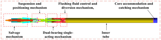
The inner assembly is mounted concentrically inside the outer assembly, leaving an annulus for mud flow. It is made up of the salvage mechanism, suspension and positioning mechanism, double-bearing single-action mechanism, flushing fluid control and diversion mechanism, and core accommodation and catching mechanism, as shown in Figure 3. It thus serves both as the container that captures and holds the core and as the component that confines the annular mud flow and governs the dynamic behavior of descent and landing.
Figure 3.
Schematic of the inner-tube assembly, the outer diameter of the inner tube is 108 mm, the core diameter is 95 mm, and the length of the entire inner-tube assembly is 10 m.
2.2. Working Principle
Continuous coring with the 216-type wireline coring tool is realized by deploying and recovering the inner assembly through the drill-string passage without tripping the entire drill string. Large-diameter systems of this class have been applied in deep and ultra-deep scientific drilling through sedimentary sequences comprising mudstone, silty mudstone, argillaceous siltstone, siltstone, and sandstone [28,29]. During deployment, the inner assembly moves downward under its submerged weight and the hydraulic action of the drilling fluid. Mud properties determine the hydrodynamic resistance and the attainable deployment velocity, while annular clearance, core-barrel wall thickness, and assembly length govern the available radial space, mass, and flexural response. These factors jointly control the contact and transport behavior of the assembly inside the drill pipe.
3. Simulation Model and Analytical Consistency Checks
3.1. Establishment of the Simulation Model
A nonlinear transient dynamics model of the wireline-coring inner-assembly/drill-pipe system is established in ANSYS Workbench 2022. The model resolves inertia, gravity, repeated contact/separation, and Coulomb friction as the assembly travels through the prescribed curved drill pipe. The transient solver updates the structural response and contact status at each time increment, enabling contact-induced bending, local stress concentration, and axial velocity loss to be tracked during deployment.
The geometry is set according to field measurements and the downhole deformation characteristics. The model comprises a 10 m inner assembly and a 30 m drill pipe divided into three 10 m sections, with a prescribed overall 15-degree S-shaped curvature representing drill-pipe bending/tortuosity. The S-shaped centerline is an imposed geometric constraint; it produces bending and wall contact but should not be interpreted as a helical-buckling shape. The two components are assembled coaxially with a uniform annular clearance and a contact pair, allowing load-dependent contact and separation to be tracked. Secondary details such as threads and small chamfers are simplified to balance computational cost and geometric fidelity. At the beginning of the transient calculation, the inner assembly is positioned coaxially and concentrically inside the drill pipe with the nominal annular clearance. No initial eccentricity, lateral deflection, or rotational velocity is imposed; only the CFD-derived axial deployment velocity is prescribed. The first wall contact therefore develops dynamically as the assembly moves through the prescribed curved geometry under gravity and contact constraints.
All degrees of freedom on the outer surface of the drill pipe are fixed to represent the radial confinement of the borehole wall and casing. The inner assembly is defined as the contact surface and the drill pipe wall as the target surface, which enables the repeated impact-separation transients to be reproduced realistically; the settings are shown in Figure 4. The inner-assembly/drill-pipe pair is defined as frictional surface-to-surface contact with a constant Coulomb friction coefficient of 0.20. Separation and subsequent re-contact are permitted. Normal-contact stiffness and contact damping are not manually calibrated; the ANSYS program-controlled settings are retained for these controls.
Figure 4.
Boundary condition setup of the simulation model, the intermediate sections of the elongated tubular components are omitted, as indicated by the arrows.
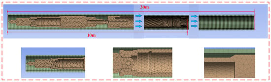
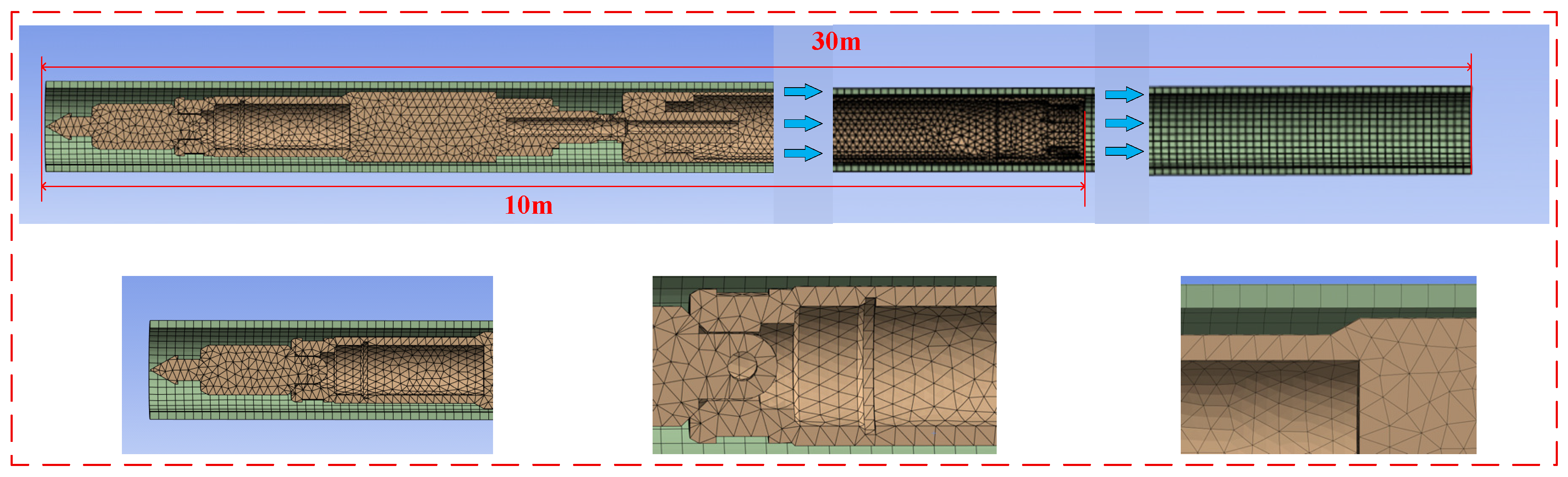
Tetrahedral elements are adopted because they fit complex curved surfaces and narrow gaps. The resulting mesh contains 165,540 nodes and 77,046 elements, with a quality measure no lower than 0.25, as shown in Figure 5.
Figure 5.
Mesh division effect, the intermediate sections of the elongated tubular components are omitted, as indicated by the arrows.
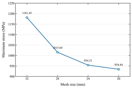
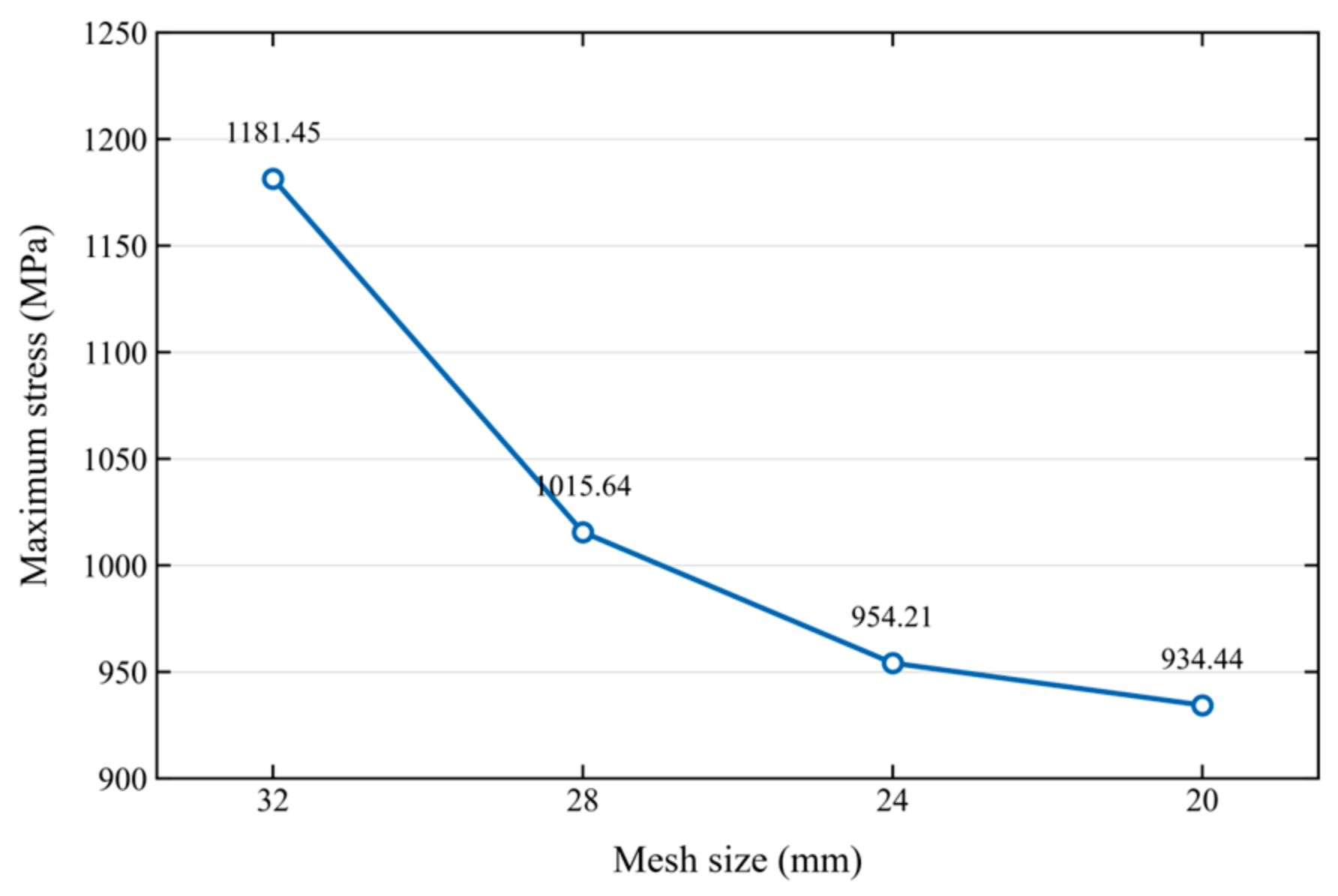
A mesh sensitivity analysis was conducted for the baseline case using mesh sizes of 32, 28, 24, and 20 mm. The variation in maximum von Mises equivalent stress progressively decreased with mesh refinement, with a relative difference of less than 5% between the 24 mm and 20 mm meshes, indicating acceptable mesh convergence. The mesh-sensitivity results are presented in the figure below. Detailed data are shown in Figure 6 below.
Figure 6.
Mesh independence verification.
The transient analysis lasts 4.7 s with automatic time stepping. The initial deployment velocity is obtained from Fluent calculations that determine the steady deployment velocity under the combined effects of gravity, buoyancy, and mud drag. Thus, mud density and viscosity affect the structural transient through the prescribed initial velocity for each operating case. The structural model does not impose a sustained differential pressure across the inner-assembly wall, and pressure-induced hoop/radial membrane stresses are outside the present scope. The CFD and structural calculations are therefore linked sequentially in one direction: Fluent supplies the steady deployment velocity used as the initial axial condition in ANSYS, and no displacement, velocity, or force information is transferred back from the transient structural model to Fluent during the calculation.
In the following results, the ANSYS ‘Equivalent Stress’ output denotes the von Mises equivalent stress. It is used to assess local material stress/yielding and is not used as a buckling or lockup criterion. For passability assessment, deployment arrest is defined operationally as |vax| < 0.01 m/s for at least 0.20 s before the assembly reaches the 30 m outlet, accompanied by an approximately flat axial-displacement history. This numerical criterion indicates sustained loss of axial motion only; it is not a helical-buckling/lockup load. Accordingly, no numerical output in the present study is used to identify the onset of classical buckling; the reported quantities are used only to assess deployment kinematics, contact-induced bending/stress, and passability.
The numerical results presented below are based on the prescribed modeling conditions, including a friction coefficient of 0.20, a 15° S-shaped drill-pipe geometry, zero imposed rotation, and simplified thread and chamfer geometries. These assumptions provide a consistent basis for systematically evaluating the effects of key parameters on the deployment dynamics, contact stresses, and passability of the inner assembly. Although variations in friction conditions and contact geometry may influence the quantitative results, the present analysis provides useful insights into the deployment behavior of the inner assembly under the investigated conditions.
3.2. Hertz-Based Analytical Benchmark and Numerical Consistency Assessment
An idealized Hertz line-contact calculation is used to establish an independent analytical scale for normal contact in the inner-assembly/drill-pipe system [30,31]. It is a simplified contact-mechanics benchmark rather than validation of the complete transient S-shaped model. The reference case uses the 6.5 mm annular clearance and a local 15-degree inclination. Hertz theory predicts normal pressure under smooth, frictionless, linear-elastic contact, whereas the ANSYS model reports transient von Mises equivalent stress with curved geometry, friction, contact separation, and re-contact. Accordingly, the outputs are interpreted with their different physical definitions and limitations in mind. The input values are listed in Table 1.
Table 1.
Baseline operating parameters.
The analytical estimate assumes homogeneous linearly elastic cylinders of uniform cross-section and locally parallel axes, a smooth frictionless contact interface, and static loading from the buoyancy-corrected weight component normal to the local pipe axis [32]. It excludes dynamic impact, frictional shear, nonuniform joints, and the imposed S-shaped trajectory, all of which are represented or approximated in the full transient structural model.
- (1)
- Effective lateral contact force
In a well inclined at 15 degrees, the gravity of the assembly has a component normal to the pipe axis that forces the assembly eccentrically against the lower wall. Before the normal contact force is computed, buoyancy is subtracted so that the effective self-weight in the mud is obtained.
The metal volume of the inner assembly is estimated as follows:
The buoyancy exerted by the drilling fluid is as follows:
The effective total gravity in the mud is as follows:
The normal contact force normal to the pipe wall (the lateral gravity component) is as follows:
- (2)
- Hertz contact equivalent radius of curvature
Because the convex cylindrical surface of the assembly contacts the concave cylindrical surface of the drill pipe, the two-cylinder equivalent curvature formula of Hertz contact is employed:
where is the outer radius of the inner assembly (convex, positive curvature), and is the inner radius of the drill pipe wall (concave, negative curvature, appearing as a minus sign in the formula).
- (3)
- Hertz equivalent combined elastic modulus
Both the inner assembly and the drill pipe are made of steel with the same elastic modulus and Poisson’s ratio (, ); according to the Hertz equivalent elastic modulus formula:
Hence the Hertz equivalent combined elastic modulus is as follows:
- (4)
- Maximum Hertz contact pressure on the contact surface
The inner assembly does not stay in uniform contact with the wall along its full 10 m length; under S-shaped curvature or local small bending, contact occurs at local rigid sections (e.g., outside the latch chamber or on the centralizing band), and the local effective line contact length is assumed to be .
For an infinitely long cylinder in line contact, the Hertz half-width of the contact zone is obtained as follows:
The peak pressure formula for cylindrical line contact then gives the maximum Hertz contact pressure:
- (5)
- Local stress scale and interpretation of the numerical results
For frictionless Hertz line contact, the maximum subsurface von Mises equivalent stress is approximately 0.56 times the peak normal contact pressure [32]. This relation is an idealized elastic stress-field estimate, not an empirical adjustment to the finite-element output.
The Hertz analytical solution yields a contact half-width of approximately 0.049 mm, a peak normal contact pressure of 5.50 MPa, and an estimated maximum subsurface von Mises equivalent stress of 3.08 MPa under idealized contact conditions. For the 6.5 mm annular clearance case, the transient finite-element model predicts a peak von Mises equivalent stress of approximately 1.86 MPa. The values are of a similar order of magnitude, but the idealized Hertz estimate and the transient finite-element peak refer to different loading conditions and stress distributions and should not be regarded as directly equivalent. The Hertz solution serves as an analytical reference supporting the physical plausibility of the simulated contact-stress response rather than an independent validation of the complete numerical model. This comparison offers an approximate stress-scale check; the separate mesh sensitivity analysis in Section 3.1 addresses numerical resolution but does not validate the full transient contact response. Nevertheless, further verification using a matched static contact model or experimental measurements is required to establish its quantitative accuracy.
4. Parametric Influence Analysis
Following the local stress benchmark, single-factor simulations are performed on the 30 m S-shaped drill-pipe model to examine how key parameters influence deployment stability, passability, and contact-induced material stress.
4.1. Influence of the Annular Clearance
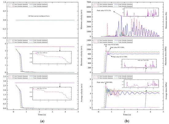
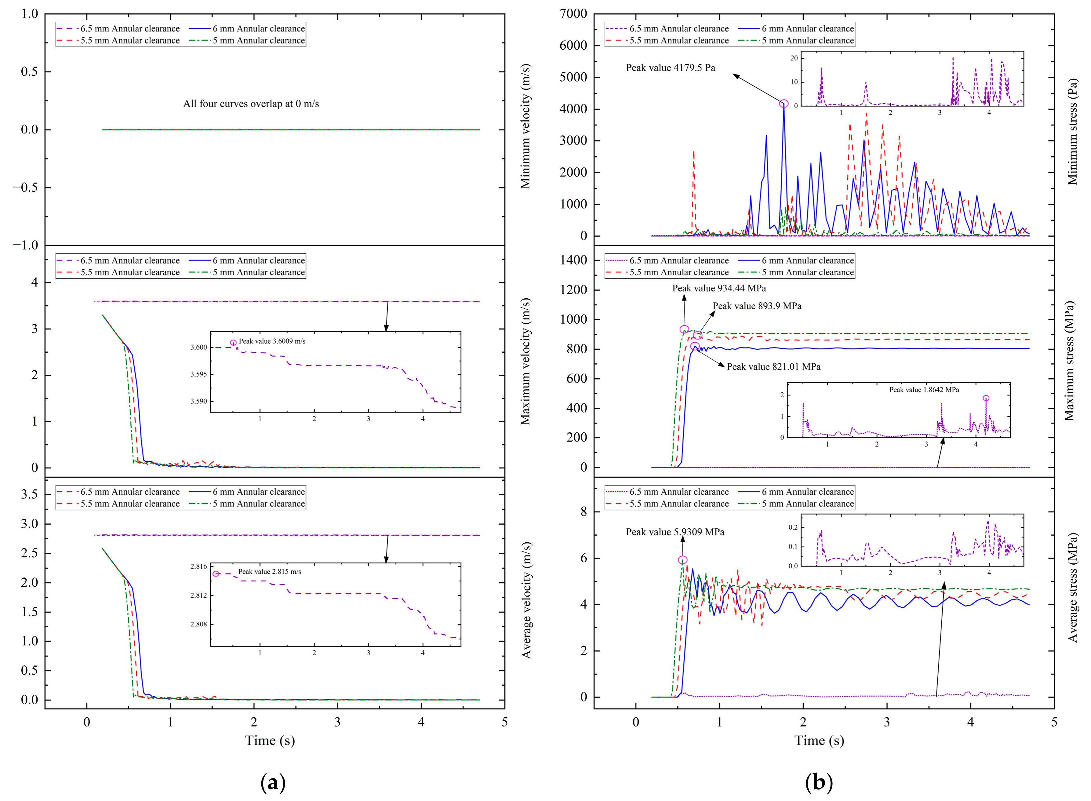
The annular clearance between the drill-pipe inner wall and the outer surface of the wireline inner assembly determines the available radial space and influences deployment passability. Four annular clearances (5.0, 5.5, 6.0, and 6.5 mm) were simulated with the remaining parameters held constant. The simulation conditions are listed in Table 2, and the corresponding deployment responses are shown in Figure 7.
Table 2.
Simulation conditions under different annular clearances.
Figure 7.
Deployment responses of the inner assembly at different annular clearances: (a) axial velocity, (b) von Mises equivalent stress.
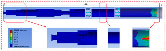
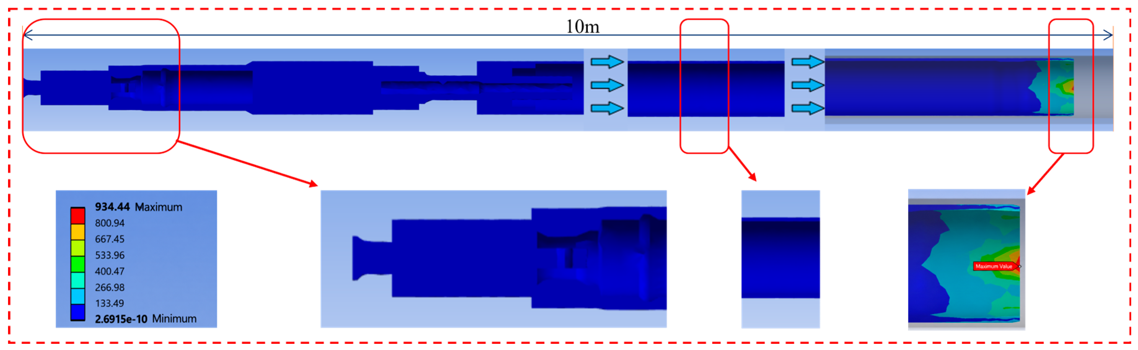
At an annular clearance of 5.0 mm, the maximum and average axial velocities decrease from approximately 3.6 and 2.8 m/s, respectively, to nearly zero at approximately 1.2 s. The equivalent stress peak reaches 934.44 MPa (Figure 8), exceeding the specified material yield strength of 750 MPa and indicating potential local yielding in the simulated case. The restricted annular clearance promotes eccentric wall contact and increased frictional resistance, resulting in sustained loss of axial motion. At annular clearances of 5.5 and 6.0 mm, the axial deployment velocity also approaches zero (Figure 7a), with equivalent stresses peak of 893.9 and 821.01 MPa, respectively. Both values exceed the specified material yield strength of 750 MPa, indicating a potential risk of localized yielding.
Figure 8.
Von Mises equivalent stress distribution of the inner assembly at an annular clearance of 5.0 mm, the intermediate sections of the elongated tubular components are omitted, as indicated by the arrows.
Under the baseline condition with an annular clearance of 6.5 mm, the axial deployment velocity decreases only slightly during travel, without significant deceleration. Over the 4.7 s simulation interval, the maximum velocity decreases only from 3.601 to approximately 3.589 m/s, while the average velocity decreases from 2.815 to approximately 2.806 m/s. The equivalent stress peak is approximately 1.86 MPa, and no deployment arrest is observed. Under the prescribed geometric and frictional conditions, the larger annular clearance reduces sustained wall contact and allows continued axial motion. Among the four annular clearances investigated, 6.5 mm is the smallest tested clearance at which successful deployment is observed, rather than a precisely established critical-clearance threshold.
4.2. Influence of the Core-Barrel Wall Thickness
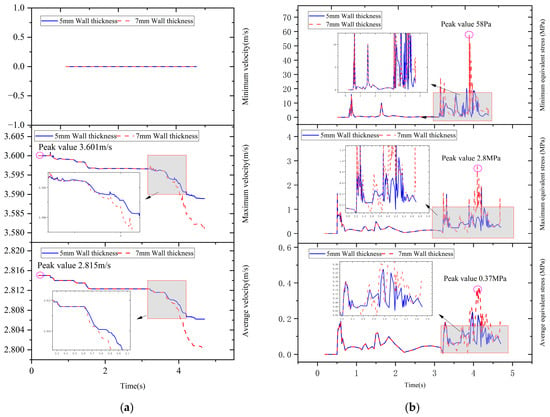
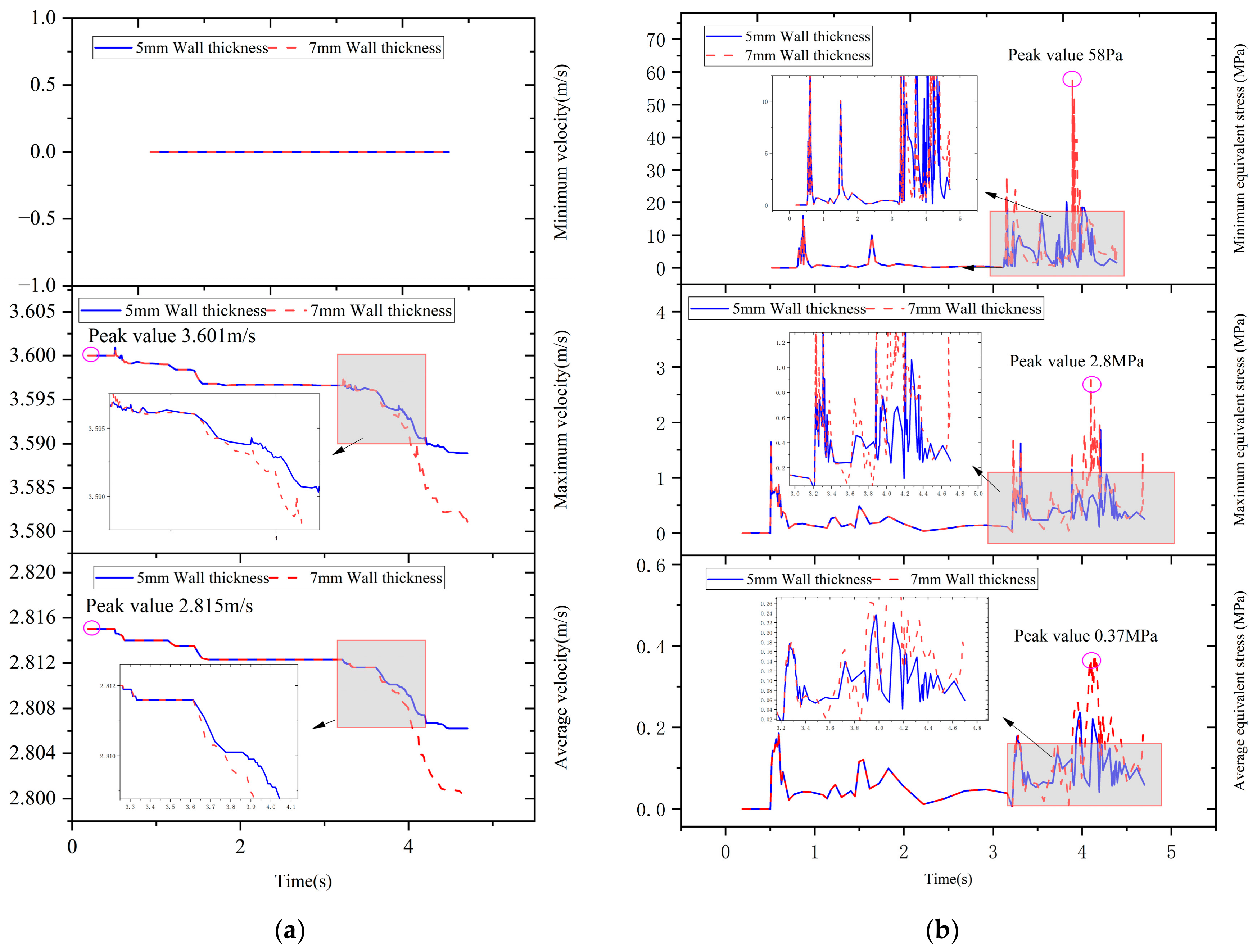
Core-barrel wall thickness affects both the flexural stiffness and self-weight of the inner assembly. With all other parameters held constant, wall thicknesses of 5 and 7 mm were examined. The simulation conditions are listed in Table 3, and the corresponding deployment responses are shown in Figure 9.
Table 3.
Simulation conditions under different core-barrel wall thicknesses.
Figure 9.
Deployment responses of the inner assembly at different core-barrel wall thicknesses: (a) axial velocity, (b) von Mises equivalent stress.
Under the baseline condition with a core-barrel wall thickness of 5 mm, the axial deployment velocity of the inner assembly exhibits only slight fluctuations and gradually decreases over the 30 m travel distance, without abrupt deceleration or sustained deployment arrest. The maximum velocity decreases from 3.601 to 3.589 m/s, while the average velocity decreases from 2.815 to 2.800 m/s. The inner assembly successfully traverses the entire drill-pipe section.
At a core-barrel wall thickness of 7 mm, the inner assembly maintains relatively stable deployment motion, although the axial velocity exhibits a more pronounced decrease than that observed in the 5 mm wall-thickness case. The local equivalent stress increases, with an equivalent stress peak of approximately 2.8 MPa, which remains below the reference material yield strength of 750 MPa. No sustained deployment arrest is observed. The increase in equivalent stress may be associated with changes in the assembly self-weight, flexural stiffness, and local contact conditions resulting from the increased wall thickness. These results indicate that under the investigated geometric and frictional conditions, transient wall contact occurs during deployment in both the 5 mm and 7 mm wall-thickness cases, but neither configuration exhibits sustained deployment arrest due to geometric constraints or accumulated contact resistance.
4.3. Influence of the Inner-Assembly Length
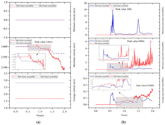
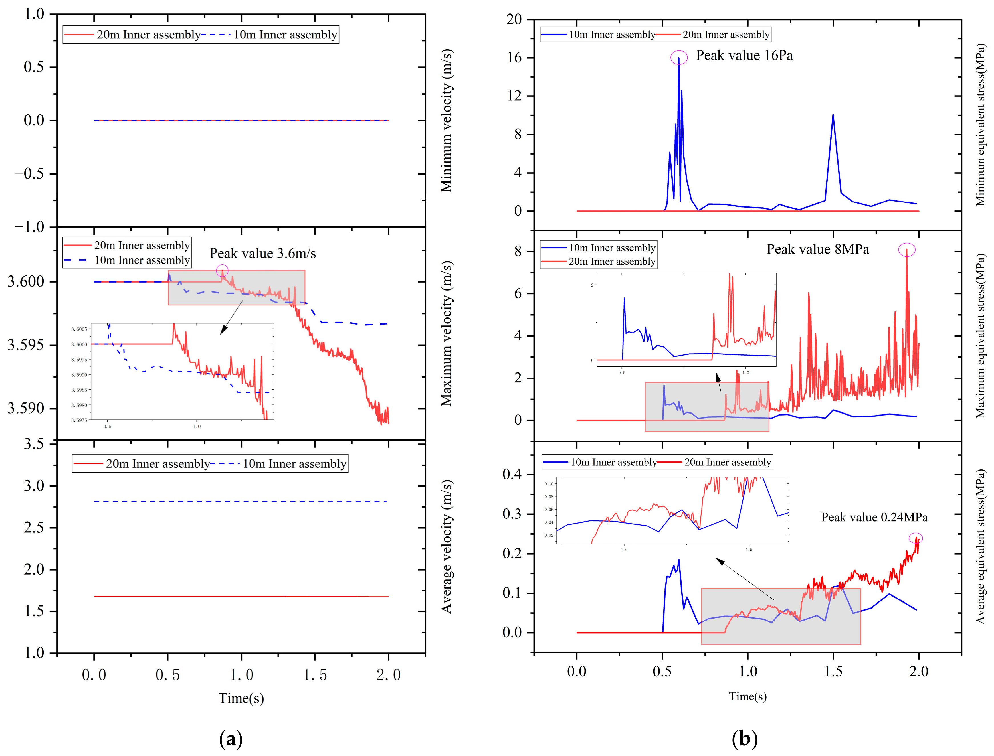
Inner-assembly length affects the total mass distribution, flexural compliance, and duration of wall interaction and can therefore influence the transient deployment response. With all other parameters held constant, inner-assembly lengths of 10 and 20 m were examined. The simulation conditions are listed in Table 4, and the corresponding deployment responses are shown in Figure 10.
Table 4.
Simulation conditions under different inner-assembly lengths.
Figure 10.
Deployment responses of the inner assembly at different inner assembly lengths: (a) axial velocity curve, (b) von Mises equivalent stress.
Under the baseline condition with a 10 m inner assembly, the axial deployment velocity exhibits only slight fluctuations over the 30 m travel distance, remaining close to its initial value with a nearly constant overall trend. Within 2.0 s, it maintained a maximum speed of approximately 3.601 m/s and only decreased by approximately 0.012 m/s. Under the investigated geometric, frictional, and loading conditions, the 10 m inner assembly successfully completes deployment without abrupt velocity attenuation or sustained deployment arrest associated with accumulated contact resistance or geometric constraints.
When the inner-assembly length is increased to 20 m, the axial deployment velocity exhibits only a slight decrease, while the overall motion remains relatively stable. Over the 2.0 s simulation interval, the axial velocity decreases to approximately 3.589 m/s, representing a reduction of about 0.011 m/s from its initial value. The equivalent stress peak reaches approximately 8 MPa, remaining below the reference material yield strength of 750 MPa, and no sustained deployment arrest is observed. Compared with the 10 m configuration, the 20 m inner assembly exhibits a slightly greater short-term velocity reduction and a higher peak local equivalent stress, suggesting that increasing the assembly length may intensify the transient contact-stress response under the investigated conditions.
4.4. Influence of the Initial Deployment Velocity
Since the viscosity and density of the drilling fluid affect the terminal settling velocity of the inner assembly, the velocity obtained from the fluid simulation was prescribed as the initial velocity in the transient structural analysis, thereby accounting for the effects of drilling fluid viscosity and density on the structural response. Mud density and viscosity influence inner-assembly deployment by altering buoyancy, viscous drag, and the surrounding flow field. They are practical operational parameters that affect the deployment velocity, force balance, and dynamic response of the inner assembly. For each case, Fluent is first solved using the density and the case-wise constant dynamic-viscosity value listed in Table 5 (5, 30, and 63 mPa·s) to obtain the steady deployment velocity. These viscosity values are the input dynamic viscosities used for the corresponding CFD cases and are not presented as a complete set of parameters for a general shear-rate-dependent power-law model. The CFD-derived deployment velocity is then prescribed as the initial axial velocity in ANSYS through the one-way CFD-to-structural workflow described in Section 3.1.
Table 5.
Simulation conditions for the combined drilling-fluid cases.
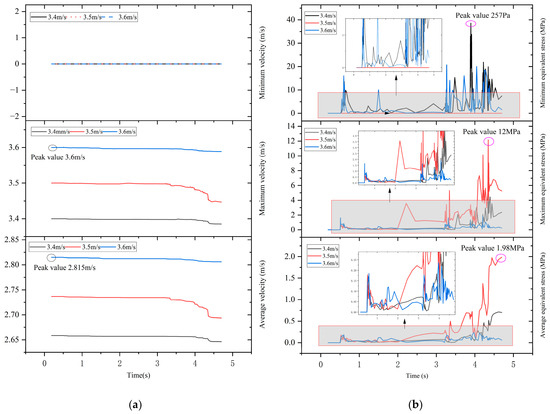
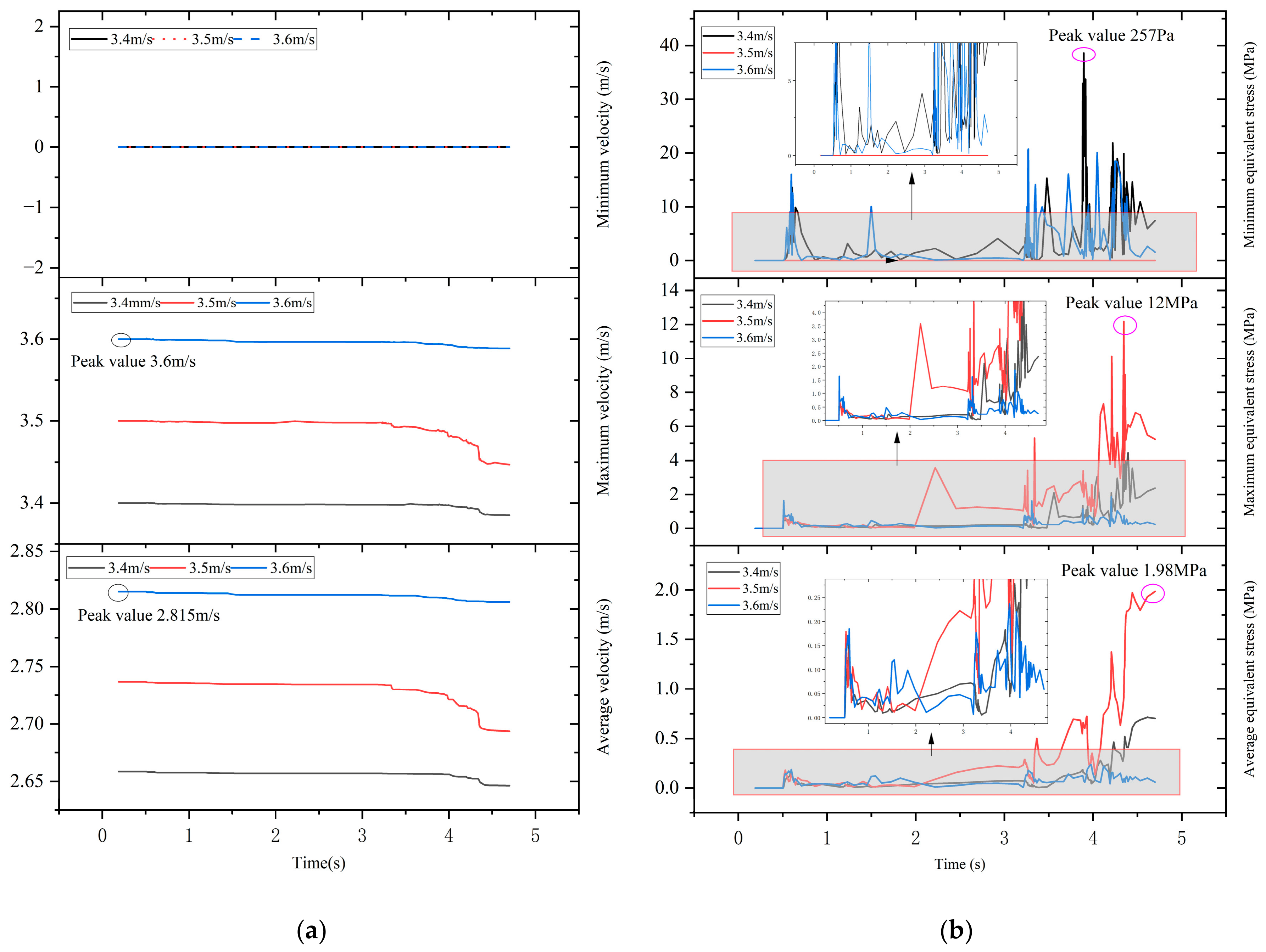
In field operations, these properties can be adjusted through conventional drilling-fluid conditioning, density by changing the concentration of weighting materials or by dilution, and viscosity by using viscosifiers, thinners, or rheology modifiers. They are routinely monitored at the surface using standard instruments such as a mud balance and a rotational viscometer or Marsh funnel. With the structural parameters fixed at baseline values, the mud density and viscosity are increased together to mimic conditions over a depth range of 3000–10,000 m, giving the three simulation cases listed in Table 5, and the deployment responses are shown in Figure 11.
Figure 11.
Deployment responses of the inner assembly at different initial velocities: (a) axial velocity curve, (b) von Mises equivalent stress.
At the end of the 4.7 s interval, the maximum-velocity curves are approximately 3.385, 3.445, and 3.601 m/s for the 3.4, 3.5, and 3.6 m/s cases, respectively. The 3.5 m/s case exhibits the largest labeled equivalent stress peak of about 12 MPa. At all three initial velocities the assembly passes the full 30 m drill pipe without sustained deployment arrest. Comparing the cases reveals a clear trend: as the initial velocity grows, the peaks on the equivalent-stress time history become more numerous and denser. The reason is that a faster fall makes the assembly cover a longer distance per unit time and strengthens its lateral inertia. When it reaches bent sections or local wall irregularities, it oscillates and tilts more readily. The stronger oscillation raises the collision frequency between the assembly wall and the drill pipe wall, and each collision shows up as a stress peak. Under the investigated simulation conditions, higher initial deployment velocities may lead to more frequent repeated contact loading. However, dedicated cyclic loading analysis, fatigue damage assessment, and wear analysis are required to quantitatively evaluate their effects on the fatigue life of the inner assembly and wear of the contact surfaces.
Drilling-fluid viscosity and density jointly influence the axial deployment velocity, which in turn affects the lateral vibration response and frequency of frictional contact of the inner assembly. The three initial deployment velocity cases investigated in this study demonstrate successful deployment under the prescribed geometric, frictional, and loading conditions. However, further parametric investigations and experimental validation are required to establish an appropriate operating velocity range and determine the critical contact frequency.
5. Conclusions
This study investigated the deployment dynamics and passability of the inner assembly of a 216-type wireline coring tool in ultra-deep wells. A nonlinear transient finite-element model was developed to examine the effects of structural parameters and CFD-derived initial deployment velocities on axial motion, wall contact, and local stress. The main conclusions are as follows:
- (1)
- Annular clearance is a key factor governing the passability of the inner assembly. Under the investigated conditions, deployment arrest occurs at clearances of 5.0, 5.5, and 6.0 mm, whereas successful passage is achieved at 6.5 mm. At a clearance of 5.0 mm, sustained eccentric contact causes the assembly to stop at approximately 1.2 s, with an equivalent stress peak of 934.44 MPa, exceeding the material yield strength of 750 MPa. Therefore, among the annular clearances investigated, 6.5 mm is the smallest tested clearance at which successful deployment of the inner assembly is observed, rather than a precisely established critical-clearance threshold.
- (2)
- Core-barrel wall thickness and inner-assembly length affect deployment dynamics through changes in structural stiffness, self-weight, and contact conditions. Both wall thicknesses (5 and 7 mm) allow for successful deployment, while the equivalent stress peak increases from approximately 1.86 to 2.8 MPa. Increasing the assembly length from 10 to 20 m slightly intensifies velocity attenuation, with a reduction of approximately 0.011 m/s over 2.0 s and an equivalent stress peak of approximately 8 MPa for the 20 m case. These results suggest that larger structural dimensions may intensify transient contact responses without necessarily improving deployment performance.
- (3)
- Drilling-fluid conditions indirectly affect the deployment dynamics through the CFD-derived initial velocity. Within the investigated velocity range of 3.4–3.6 m/s, the inner assembly successfully completes deployment without arrest. Higher initial velocities generally lead to more frequent equivalent stress fluctuations, with an equivalent stress peak of approximately 12 MPa observed at 3.5 m/s. Therefore, deployment velocity should be selected by balancing deployment efficiency and transient contact stresses.
- (4)
- The findings provide case-specific guidance for improving the deployment performance of wireline coring tools. The conclusions are limited to the prescribed 15° S-shaped drill-pipe geometry, a friction coefficient of 0.20, zero imposed rotation, simplified component geometry, and CFD-informed initial velocities. Because friction and contact geometry can alter predicted arrest and peak stresses, further sensitivity analyses, matched experimental validation, and dedicated fatigue assessment are needed before general design limits or structural-safety recommendations can be established.
Author Contributions
L.C.: Writing—Original draft, Conceptualization, Methodology, and Validation; J.L.: Data curation, Conceptualization, Resources, Software, and Visualization; Z.Z.: Methodology, Resources, Writing—Review and Editing, and Project administration; H.Z.: Supervision, Resources, and Investigation. All authors have read and agreed to the published version of the manuscript.
Funding
This study was funded by the Deep Earth Probe and Mineral Resources Exploration-National Science and Technology Major Project (2024ZD1000901); China Geological Survey Project “Efficient and Precise Exploration Technology for Solid Mineral Resources and Upgrading and Application of Automated Drilling Equipment” (DD20240205512).
Institutional Review Board Statement
Not applicable.
Informed Consent Statement
Not applicable.
Data Availability Statement
All data are available from the corresponding author upon reasonable request.
Conflicts of Interest
The authors declare no conflict of interest.
References
- Yu, J.K.; Cui, W.X. Explore China’s stakeholders in the exploration and exploitation of mineral resources in deep seabed areas: Identification, challenges and prospects. Ocean Coast. Manag. 2023, 244, 106712. [Google Scholar] [CrossRef] [Scilit]
- Yang, B.Y.; Zhang, H.; Wu, B.K.; Lv, K.H.; Yuan, R.; Zhou, Y.T.; Yang, Z. Study on prediction of annular trap pressure in ultra-high temperature and high pressure gas wells. Pet. Sci. 2026, 23, 1307–1318. [Google Scholar] [CrossRef] [Scilit]
- Zhu, G.Y.; Huang, H.P. Ultradeep drilling beyond 10 km revealing new insights into Earth systems and resources. Commun. Earth Environ. 2026, 7, 124. [Google Scholar] [CrossRef] [Scilit]
- Hu, Y.-Q.; Xie, J.; Xue, S.-N.; Xu, M.; Fu, C.-H.; He, H.-L.; Liu, Z.-Q.; Ma, S.-M.; Sun, S.-Q.; Wang, C.-L. Research and application of thermal insulation effect of natural gas hydrate freezing corer based on the wireline-coring principle. Pet. Sci. 2022, 19, 1291–1304. [Google Scholar] [CrossRef] [Scilit]
- Li, F.L.; Wang, H.C.; Xin, Z.C.; Wu, J.S.; Luo, X.L.; Zhang, G.X. Research and application of key technologies for long-distance wire-line core drilling in horizontal boreholes. Drill. Eng. 2025, 52, 77–85. [Google Scholar]
- Cocci, M.; Barletta, S.; Berzi, L.; Capitani, R.; Delogu, M.; Mariottoni, E.; Sacchetto, M.; Pugi, L. Design and simulation of a wireline core drilling device for near-shore applications. IOP Conf. Ser. Mater. Sci. Eng. 2023, 1275, 012033. [Google Scholar] [CrossRef] [Scilit]
- Wang, J.L.; Peng, F.F.; Wan, B.Y.; Zhou, Y. Structural optimization and simulation analysis of high reliability wireline coring drilling tools for submarine drilling rigs. Coal Geol. Explor. 2019, 47, 206–211. [Google Scholar]
- Freudenthal, T.; Wefer, G. Drilling cores on the sea floor with the remote-controlled sea floor drilling rig MeBo. Geosci. Instrum. Method. Data Syst. 2013, 2, 329–337. [Google Scholar] [CrossRef] [Scilit]
- Wang, W.; Wang, S.; Li, B.; Xiang, J. Development and application of a rope core hydraulic closed-core mechanism for loose and broken strata. Appl. Sci. 2024, 14, 10849. [Google Scholar] [CrossRef] [Scilit]
- Wei, H.; Zhu, Z.; Wang, J.; Liu, K.; Jia, M.H.; Jia, W.; Liu, G. Development and experimental study of H-caliber hydraulic lifting wireline coring tool. Drill. Eng. 2025, 52, 31–38. [Google Scholar]
- Wang, Y.; Li, X.; Ma, Y.; Shi, S.; Zhou, Q.; Chou, J.; Chen, J. Design and Experiments of Directional Core Drilling Tool. Appl. Sci. 2025, 15, 11612. [Google Scholar] [CrossRef] [Scilit]
- Lu, Q.; Qin, R.; Yu, Y.; Qi, L.; Xie, W.; Lu, H.; Xu, B.; Shi, H.; Xu, C.; Li, X. The design and application of a new wireline pressure coring system for the Guangzhou Marine Geological Survey methane hydrate expedition in the South China Sea. Appl. Sci. 2024, 14, 6753. [Google Scholar] [CrossRef] [Scilit]
- Yue, W.; Liang, J.; Zhang, H.; Zhu, L.; Zhu, L.; Wang, Z.; Wang, Y. Challenges and Prospects of Wireline Coring Technology for Ultra-Deep Continental Scientific Drilling. Drill. Eng. 2026, 53, 1–13. [Google Scholar]
- Wang, J.; Chen, C.; Hu, Y.; Wan, B.; Xiao, B.; Xu, Z.; Hu, S.; Yu, M. Scheme design and flow performance analysis of double-bits combination wireline coring technology for seafloor drill. Mar. Georesour. Geotechnol. 2025, 43, 1–15. [Google Scholar] [CrossRef] [Scilit]
- Guo, D.; Li, J.; Wang, D.; Zhang, Y.; Fang, X.; Xie, H. Structural improvement of differential motion assembly in in situ pressure-preserved coring system using CFD simulation. Appl. Sci. 2023, 13, 4108. [Google Scholar] [CrossRef] [Scilit]
- Wang, Y.; Qian, C.; Kong, L.; Zhou, Q.; Gong, J. Design optimization for the thin-walled joint thread of a coring tool used for deep boreholes. Appl. Sci. 2020, 10, 2669. [Google Scholar] [CrossRef] [Scilit]
- Liu, J.; Sun, J.; Jiang, G.; Yu, Y. A study on the influence of core stability on the coring process of long-barrel coring tools. Processes 2024, 12, 2847. [Google Scholar] [CrossRef] [Scilit]
- Huang, Y.; Zheng, W.; Zhang, G.; Chen, Y.; Qin, J. Laboratory investigation on inhibition of polyvinyl alcohol used for wireline coring drilling. J. Pet. Explor. Prod. Technol. 2024, 14, 2239–2255. [Google Scholar] [CrossRef] [Scilit]
- Peng, X.Y.; Jiang, H.D. Drilling fluid formula and performance for slow angle wireline core drilling. Int. J. Heat Technol. 2020, 38, 479–486. [Google Scholar] [CrossRef] [Scilit]
- Tan, S.; Li, Z.; Yang, Y.; Liu, H.; Wang, M.; Cheng, C.; Hu, Y. Design and shallow-hole validation of a low-flow mud-pulse MWD pulser head for wireline coring. Appl. Sci. 2026, 16, 3934. [Google Scholar] [CrossRef] [Scilit]
- Sun, Y.; Liu, Y.; Qin, X.; Dou, Z.; Feng, Z.; Yang, G. Investigating drillstring vibration and stability in coring drilling. Energies 2022, 15, 5234. [Google Scholar] [CrossRef] [Scilit]
- Mohammad, H.; Munshi, B. Experimental study of wall effect on hollow cylindrical particle settling in Newtonian and non-Newtonian fluids in cylindrical channels. Powder Technol. 2023, 428, 118858. [Google Scholar] [CrossRef] [Scilit]
- Mohammad, H.; Munshi, B. Experimental estimation of the settling velocity and drag coefficient of the hollow cylindrical particles settling in non-Newtonian fluids in an annular channel. Can. J. Chem. Eng. 2023, 101, 6632–6640. [Google Scholar] [CrossRef] [Scilit]
- Li, B.; Zhang, P.; Zhu, X.; Zhang, W.; Dong, L. Numerical analysis of nonlinear buckling response of an axially movable constrained drill string in horizontal wells with complex structures. Geoenergy Sci. Eng. 2024, 241, 213147. [Google Scholar] [CrossRef] [Scilit]
- Kuleshova, L.S.; I Akhmetshina, D.; A Fatkullin, A.; A Abdulmanov, A. The effect of axial loading on drill string deformation. IOP Conf. Ser. Mater. Sci. Eng. 2020, 952, 012057. [Google Scholar] [CrossRef] [Scilit]
- Li, Z.; Chen, L.; Yuan, F.; Zhao, L. Study on helical post-buckling of motional coiled tubing in horizontal wells. J. Pet. Explor. Prod. Technol. 2025, 15, 111. [Google Scholar] [CrossRef] [Scilit]
- Shi, Y.; Li, C. Flow Field Simulation of a Hydrogeological Exploration Drill Bit for Switching between Coring Drilling and Non-Coring Drilling. Appl. Sci. 2024, 14, 4893. [Google Scholar] [CrossRef] [Scilit]
- Zhang, H.; Zhu, Y.; Wang, W.; Yan, J.; Cao, L.; Wang, W. Feasibility of large-diameter wireline coring technology for ultra-deep scientific drilling: Experimental verification from the CCSD-SK-2 East Borehole. Drill. Eng. 2026, 53, 94–102. [Google Scholar]
- Gao, Y.; Wang, P.; Wang, C.; Ren, Y.; Wang, G.; Liu, W.; Cheng, R. Well site selecting, core profile characteristics and distribution of the special lithology in CCSD-SK II. Acta Geol. Sin. 2008, 82, 669–675. [Google Scholar]
- Li, J.; Xie, H.; Chen, L.; Li, C.; He, Z. Exploring deep-rock mechanics through mechanical analysis of hard-rock in situ coring system. Adv. Civ. Eng. 2020, 2020, 8899156. [Google Scholar] [CrossRef] [Scilit]
- Liu, Q.; Zhou, B.; Chen, F.; Li, N.; Xie, J.; Zhao, M.; Di, Q.; Feng, C.; Song, S.; Yin, C. Optimal design and nonlinear dynamic characteristics of titanium/steel drill pipe composite drill string for ultra-deep drilling. Sci. Rep. 2023, 13, 20491. [Google Scholar] [CrossRef] [Scilit] [PubMed]
- Chandrasekaran, N.; Haisler, W.E.; Goforth, R.E. Finite element analysis of Hertz contact problem with friction. Finite Elem. Anal. Des. 1987, 3, 39–56. [Google Scholar] [CrossRef] [Scilit]







Disclaimer/Publisher’s Note: The statements, opinions and data contained in all publications are solely those of the individual author(s) and contributor(s) and not of MDPI and/or the editor(s). MDPI and/or the editor(s) disclaim responsibility for any injury to people or property resulting from any ideas, methods, instructions or products referred to in the content. |
© 2026 by the authors. Licensee MDPI, Basel, Switzerland. This article is an open access article distributed under the terms and conditions of the Creative Commons Attribution (CC BY) license.